JP5558450B2 - Dose display device, dose confirmation device, dose display method, drug injection device - Google Patents
Dose display device, dose confirmation device, dose display method, drug injection deviceDownload PDFInfo
- Publication number
- JP5558450B2 JP5558450B2JP2011226110AJP2011226110AJP5558450B2JP 5558450 B2JP5558450 B2JP 5558450B2JP 2011226110 AJP2011226110 AJP 2011226110AJP 2011226110 AJP2011226110 AJP 2011226110AJP 5558450 B2JP5558450 B2JP 5558450B2
- Authority
- JP
- Japan
- Prior art keywords
- dose
- matrix
- drug
- dose setting
- housing
- Prior art date
- Legal status (The legal status is an assumption and is not a legal conclusion. Google has not performed a legal analysis and makes no representation as to the accuracy of the status listed.)
- Expired - Fee Related
Links
- 238000002347injectionMethods0.000titleclaimsabstractdescription353
- 239000007924injectionSubstances0.000titleclaimsabstractdescription353
- 239000003814drugSubstances0.000titleclaimsabstractdescription228
- 229940079593drugDrugs0.000titleclaimsabstractdescription221
- 238000000034methodMethods0.000titleclaimsdescription39
- 238000012790confirmationMethods0.000titleclaimsdescription26
- 239000011159matrix materialSubstances0.000claimsabstractdescription261
- 230000007246mechanismEffects0.000claimsabstractdescription105
- 238000011287therapeutic doseMethods0.000claimsabstractdescription37
- 230000033001locomotionEffects0.000claimsdescription52
- 230000007704transitionEffects0.000claimsdescription31
- 239000012530fluidSubstances0.000claimsdescription30
- 239000004020conductorSubstances0.000claimsdescription19
- 238000001514detection methodMethods0.000claimsdescription16
- 238000004891communicationMethods0.000claimsdescription8
- 230000004323axial lengthEffects0.000claimsdescription7
- 230000002829reductive effectEffects0.000claimsdescription3
- 230000000007visual effectEffects0.000claimsdescription3
- 241000251556ChordataSpecies0.000claims1
- 238000007667floatingMethods0.000abstractdescription9
- 230000008901benefitEffects0.000description24
- 230000008569processEffects0.000description22
- 239000002184metalSubstances0.000description19
- 229910052751metalInorganic materials0.000description19
- 230000000712assemblyEffects0.000description14
- 238000000429assemblyMethods0.000description14
- 230000006870functionEffects0.000description14
- 229920003023plasticPolymers0.000description12
- 238000004519manufacturing processMethods0.000description11
- 230000015654memoryEffects0.000description11
- 239000004033plasticSubstances0.000description11
- 238000013461designMethods0.000description9
- 230000037452primingEffects0.000description8
- 230000009471actionEffects0.000description7
- 239000000853adhesiveSubstances0.000description7
- 230000008859changeEffects0.000description7
- 210000003811fingerAnatomy0.000description7
- 238000003825pressingMethods0.000description7
- 230000006835compressionEffects0.000description6
- 238000007906compressionMethods0.000description6
- NOESYZHRGYRDHS-UHFFFAOYSA-NinsulinChemical compoundN1C(=O)C(NC(=O)C(CCC(N)=O)NC(=O)C(CCC(O)=O)NC(=O)C(C(C)C)NC(=O)C(NC(=O)CN)C(C)CC)CSSCC(C(NC(CO)C(=O)NC(CC(C)C)C(=O)NC(CC=2C=CC(O)=CC=2)C(=O)NC(CCC(N)=O)C(=O)NC(CC(C)C)C(=O)NC(CCC(O)=O)C(=O)NC(CC(N)=O)C(=O)NC(CC=2C=CC(O)=CC=2)C(=O)NC(CSSCC(NC(=O)C(C(C)C)NC(=O)C(CC(C)C)NC(=O)C(CC=2C=CC(O)=CC=2)NC(=O)C(CC(C)C)NC(=O)C(C)NC(=O)C(CCC(O)=O)NC(=O)C(C(C)C)NC(=O)C(CC(C)C)NC(=O)C(CC=2NC=NC=2)NC(=O)C(CO)NC(=O)CNC2=O)C(=O)NCC(=O)NC(CCC(O)=O)C(=O)NC(CCCNC(N)=N)C(=O)NCC(=O)NC(CC=3C=CC=CC=3)C(=O)NC(CC=3C=CC=CC=3)C(=O)NC(CC=3C=CC(O)=CC=3)C(=O)NC(C(C)O)C(=O)N3C(CCC3)C(=O)NC(CCCCN)C(=O)NC(C)C(O)=O)C(=O)NC(CC(N)=O)C(O)=O)=O)NC(=O)C(C(C)CC)NC(=O)C(CO)NC(=O)C(C(C)O)NC(=O)C1CSSCC2NC(=O)C(CC(C)C)NC(=O)C(NC(=O)C(CCC(N)=O)NC(=O)C(CC(N)=O)NC(=O)C(NC(=O)C(N)CC=1C=CC=CC=1)C(C)C)CC1=CN=CN1NOESYZHRGYRDHS-UHFFFAOYSA-N0.000description6
- 230000001070adhesive effectEffects0.000description5
- 239000000463materialSubstances0.000description5
- 238000012986modificationMethods0.000description5
- 230000004048modificationEffects0.000description5
- 230000036961partial effectEffects0.000description5
- 230000001225therapeutic effectEffects0.000description5
- 230000005540biological transmissionEffects0.000description4
- 238000010276constructionMethods0.000description4
- 238000009434installationMethods0.000description4
- 230000000670limiting effectEffects0.000description4
- 102000004877InsulinHuman genes0.000description3
- 230000009286beneficial effectEffects0.000description3
- 238000004364calculation methodMethods0.000description3
- 230000000295complement effectEffects0.000description3
- 238000010586diagramMethods0.000description3
- 230000000694effectsEffects0.000description3
- 239000011521glassSubstances0.000description3
- 229940125396insulinDrugs0.000description3
- 238000005192partitionMethods0.000description3
- 230000002441reversible effectEffects0.000description3
- 238000012795verificationMethods0.000description3
- 108090001061InsulinProteins0.000description2
- PXHVJJICTQNCMI-UHFFFAOYSA-NNickelChemical compound[Ni]PXHVJJICTQNCMI-UHFFFAOYSA-N0.000description2
- PPBRXRYQALVLMV-UHFFFAOYSA-NStyreneChemical compoundC=CC1=CC=CC=C1PPBRXRYQALVLMV-UHFFFAOYSA-N0.000description2
- 238000004026adhesive bondingMethods0.000description2
- 238000013459approachMethods0.000description2
- 230000007812deficiencyEffects0.000description2
- 238000001802infusionMethods0.000description2
- 238000003780insertionMethods0.000description2
- 230000037431insertionEffects0.000description2
- 239000007788liquidSubstances0.000description2
- 230000013011matingEffects0.000description2
- 230000003287optical effectEffects0.000description2
- 239000003973paintSubstances0.000description2
- 238000007747platingMethods0.000description2
- 230000001681protective effectEffects0.000description2
- 230000009467reductionEffects0.000description2
- 230000000717retained effectEffects0.000description2
- 238000000926separation methodMethods0.000description2
- 229940126585therapeutic drugDrugs0.000description2
- 210000003813thumbAnatomy0.000description2
- 238000003466weldingMethods0.000description2
- RYGMFSIKBFXOCR-UHFFFAOYSA-NCopperChemical compound[Cu]RYGMFSIKBFXOCR-UHFFFAOYSA-N0.000description1
- 206010013642DroolingDiseases0.000description1
- 101000976075Homo sapiens InsulinProteins0.000description1
- 102000002265Human Growth HormoneHuman genes0.000description1
- 108010000521Human Growth HormoneProteins0.000description1
- 239000000854Human Growth HormoneSubstances0.000description1
- 235000013290Sagittaria latifoliaNutrition0.000description1
- 208000008630SialorrheaDiseases0.000description1
- 206010057362UnderdoseDiseases0.000description1
- 230000006978adaptationEffects0.000description1
- 230000002411adverseEffects0.000description1
- 229940090047auto-injectorDrugs0.000description1
- 230000015572biosynthetic processEffects0.000description1
- 239000011248coating agentSubstances0.000description1
- 238000000576coating methodMethods0.000description1
- 235000015246common arrowheadNutrition0.000description1
- 239000002131composite materialSubstances0.000description1
- 230000001010compromised effectEffects0.000description1
- 229910052802copperInorganic materials0.000description1
- 239000010949copperSubstances0.000description1
- 238000012937correctionMethods0.000description1
- 230000006378damageEffects0.000description1
- 230000003247decreasing effectEffects0.000description1
- 230000007547defectEffects0.000description1
- 230000002950deficientEffects0.000description1
- 206010012601diabetes mellitusDiseases0.000description1
- 238000003745diagnosisMethods0.000description1
- 238000009826distributionMethods0.000description1
- 239000003640drug residueSubstances0.000description1
- 230000009977dual effectEffects0.000description1
- 238000009429electrical wiringMethods0.000description1
- 238000005516engineering processMethods0.000description1
- 239000004744fabricSubstances0.000description1
- 239000000945fillerSubstances0.000description1
- 239000006260foamSubstances0.000description1
- 239000002783friction materialSubstances0.000description1
- PCHJSUWPFVWCPO-UHFFFAOYSA-NgoldChemical compound[Au]PCHJSUWPFVWCPO-UHFFFAOYSA-N0.000description1
- 229910052737goldInorganic materials0.000description1
- 239000010931goldSubstances0.000description1
- 239000011796hollow space materialSubstances0.000description1
- 238000007373indentationMethods0.000description1
- 238000011900installation processMethods0.000description1
- 239000004973liquid crystal related substanceSubstances0.000description1
- 230000006386memory functionEffects0.000description1
- 150000002739metalsChemical class0.000description1
- 238000002156mixingMethods0.000description1
- 238000000465mouldingMethods0.000description1
- 229910052759nickelInorganic materials0.000description1
- 230000008447perceptionEffects0.000description1
- 230000002093peripheral effectEffects0.000description1
- 230000036316preloadEffects0.000description1
- 238000002360preparation methodMethods0.000description1
- 230000002265preventionEffects0.000description1
- 230000002685pulmonary effectEffects0.000description1
- 230000005855radiationEffects0.000description1
- 230000004044responseEffects0.000description1
- 230000008054signal transmissionEffects0.000description1
- 239000007787solidSubstances0.000description1
- 239000000243solutionSubstances0.000description1
- 230000000153supplemental effectEffects0.000description1
- 238000012360testing methodMethods0.000description1
- 238000012546transferMethods0.000description1
- 230000001960triggered effectEffects0.000description1
- 238000002604ultrasonographyMethods0.000description1
Images


Classifications
- A—HUMAN NECESSITIES
- A61—MEDICAL OR VETERINARY SCIENCE; HYGIENE
- A61M—DEVICES FOR INTRODUCING MEDIA INTO, OR ONTO, THE BODY; DEVICES FOR TRANSDUCING BODY MEDIA OR FOR TAKING MEDIA FROM THE BODY; DEVICES FOR PRODUCING OR ENDING SLEEP OR STUPOR
- A61M5/00—Devices for bringing media into the body in a subcutaneous, intra-vascular or intramuscular way; Accessories therefor, e.g. filling or cleaning devices, arm-rests
- A61M5/178—Syringes
- A61M5/31—Details
- A61M5/315—Pistons; Piston-rods; Guiding, blocking or restricting the movement of the rod or piston; Appliances on the rod for facilitating dosing ; Dosing mechanisms
- A61M5/31533—Dosing mechanisms, i.e. setting a dose
- A61M5/31535—Means improving security or handling thereof, e.g. blocking means, means preventing insufficient dosing, means allowing correction of overset dose
- A—HUMAN NECESSITIES
- A61—MEDICAL OR VETERINARY SCIENCE; HYGIENE
- A61M—DEVICES FOR INTRODUCING MEDIA INTO, OR ONTO, THE BODY; DEVICES FOR TRANSDUCING BODY MEDIA OR FOR TAKING MEDIA FROM THE BODY; DEVICES FOR PRODUCING OR ENDING SLEEP OR STUPOR
- A61M5/00—Devices for bringing media into the body in a subcutaneous, intra-vascular or intramuscular way; Accessories therefor, e.g. filling or cleaning devices, arm-rests
- A61M5/178—Syringes
- A61M5/31—Details
- A61M5/315—Pistons; Piston-rods; Guiding, blocking or restricting the movement of the rod or piston; Appliances on the rod for facilitating dosing ; Dosing mechanisms
- A61M5/31533—Dosing mechanisms, i.e. setting a dose
- A61M5/31545—Setting modes for dosing
- A61M5/31548—Mechanically operated dose setting member
- A61M5/3155—Mechanically operated dose setting member by rotational movement of dose setting member, e.g. during setting or filling of a syringe
- A61M5/31551—Mechanically operated dose setting member by rotational movement of dose setting member, e.g. during setting or filling of a syringe including axial movement of dose setting member
- A—HUMAN NECESSITIES
- A61—MEDICAL OR VETERINARY SCIENCE; HYGIENE
- A61M—DEVICES FOR INTRODUCING MEDIA INTO, OR ONTO, THE BODY; DEVICES FOR TRANSDUCING BODY MEDIA OR FOR TAKING MEDIA FROM THE BODY; DEVICES FOR PRODUCING OR ENDING SLEEP OR STUPOR
- A61M5/00—Devices for bringing media into the body in a subcutaneous, intra-vascular or intramuscular way; Accessories therefor, e.g. filling or cleaning devices, arm-rests
- A61M5/178—Syringes
- A61M5/31—Details
- A61M5/315—Pistons; Piston-rods; Guiding, blocking or restricting the movement of the rod or piston; Appliances on the rod for facilitating dosing ; Dosing mechanisms
- A61M5/31565—Administration mechanisms, i.e. constructional features, modes of administering a dose
- A61M5/31566—Means improving security or handling thereof
- A—HUMAN NECESSITIES
- A61—MEDICAL OR VETERINARY SCIENCE; HYGIENE
- A61M—DEVICES FOR INTRODUCING MEDIA INTO, OR ONTO, THE BODY; DEVICES FOR TRANSDUCING BODY MEDIA OR FOR TAKING MEDIA FROM THE BODY; DEVICES FOR PRODUCING OR ENDING SLEEP OR STUPOR
- A61M5/00—Devices for bringing media into the body in a subcutaneous, intra-vascular or intramuscular way; Accessories therefor, e.g. filling or cleaning devices, arm-rests
- A61M5/178—Syringes
- A61M5/31—Details
- A61M5/315—Pistons; Piston-rods; Guiding, blocking or restricting the movement of the rod or piston; Appliances on the rod for facilitating dosing ; Dosing mechanisms
- A61M5/31565—Administration mechanisms, i.e. constructional features, modes of administering a dose
- A61M5/31576—Constructional features or modes of drive mechanisms for piston rods
- A61M5/31583—Constructional features or modes of drive mechanisms for piston rods based on rotational translation, i.e. movement of piston rod is caused by relative rotation between the user activated actuator and the piston rod
- A61M5/31585—Constructional features or modes of drive mechanisms for piston rods based on rotational translation, i.e. movement of piston rod is caused by relative rotation between the user activated actuator and the piston rod performed by axially moving actuator, e.g. an injection button
- G—PHYSICS
- G01—MEASURING; TESTING
- G01D—MEASURING NOT SPECIALLY ADAPTED FOR A SPECIFIC VARIABLE; ARRANGEMENTS FOR MEASURING TWO OR MORE VARIABLES NOT COVERED IN A SINGLE OTHER SUBCLASS; TARIFF METERING APPARATUS; MEASURING OR TESTING NOT OTHERWISE PROVIDED FOR
- G01D5/00—Mechanical means for transferring the output of a sensing member; Means for converting the output of a sensing member to another variable where the form or nature of the sensing member does not constrain the means for converting; Transducers not specially adapted for a specific variable
- G01D5/12—Mechanical means for transferring the output of a sensing member; Means for converting the output of a sensing member to another variable where the form or nature of the sensing member does not constrain the means for converting; Transducers not specially adapted for a specific variable using electric or magnetic means
- G01D5/244—Mechanical means for transferring the output of a sensing member; Means for converting the output of a sensing member to another variable where the form or nature of the sensing member does not constrain the means for converting; Transducers not specially adapted for a specific variable using electric or magnetic means influencing characteristics of pulses or pulse trains; generating pulses or pulse trains
- G01D5/249—Mechanical means for transferring the output of a sensing member; Means for converting the output of a sensing member to another variable where the form or nature of the sensing member does not constrain the means for converting; Transducers not specially adapted for a specific variable using electric or magnetic means influencing characteristics of pulses or pulse trains; generating pulses or pulse trains using pulse code
- G01D5/2497—Absolute encoders
- G—PHYSICS
- G01—MEASURING; TESTING
- G01D—MEASURING NOT SPECIALLY ADAPTED FOR A SPECIFIC VARIABLE; ARRANGEMENTS FOR MEASURING TWO OR MORE VARIABLES NOT COVERED IN A SINGLE OTHER SUBCLASS; TARIFF METERING APPARATUS; MEASURING OR TESTING NOT OTHERWISE PROVIDED FOR
- G01D5/00—Mechanical means for transferring the output of a sensing member; Means for converting the output of a sensing member to another variable where the form or nature of the sensing member does not constrain the means for converting; Transducers not specially adapted for a specific variable
- G01D5/12—Mechanical means for transferring the output of a sensing member; Means for converting the output of a sensing member to another variable where the form or nature of the sensing member does not constrain the means for converting; Transducers not specially adapted for a specific variable using electric or magnetic means
- G01D5/25—Selecting one or more conductors or channels from a plurality of conductors or channels, e.g. by closing contacts
- A—HUMAN NECESSITIES
- A61—MEDICAL OR VETERINARY SCIENCE; HYGIENE
- A61B—DIAGNOSIS; SURGERY; IDENTIFICATION
- A61B17/00—Surgical instruments, devices or methods
- A61B2017/00477—Coupling
- A61B2017/00482—Coupling with a code
- A—HUMAN NECESSITIES
- A61—MEDICAL OR VETERINARY SCIENCE; HYGIENE
- A61M—DEVICES FOR INTRODUCING MEDIA INTO, OR ONTO, THE BODY; DEVICES FOR TRANSDUCING BODY MEDIA OR FOR TAKING MEDIA FROM THE BODY; DEVICES FOR PRODUCING OR ENDING SLEEP OR STUPOR
- A61M5/00—Devices for bringing media into the body in a subcutaneous, intra-vascular or intramuscular way; Accessories therefor, e.g. filling or cleaning devices, arm-rests
- A61M5/178—Syringes
- A61M5/24—Ampoule syringes, i.e. syringes with needle for use in combination with replaceable ampoules or carpules, e.g. automatic
- A61M2005/2403—Ampoule inserted into the ampoule holder
- A61M2005/2407—Ampoule inserted into the ampoule holder from the rear
- A—HUMAN NECESSITIES
- A61—MEDICAL OR VETERINARY SCIENCE; HYGIENE
- A61M—DEVICES FOR INTRODUCING MEDIA INTO, OR ONTO, THE BODY; DEVICES FOR TRANSDUCING BODY MEDIA OR FOR TAKING MEDIA FROM THE BODY; DEVICES FOR PRODUCING OR ENDING SLEEP OR STUPOR
- A61M5/00—Devices for bringing media into the body in a subcutaneous, intra-vascular or intramuscular way; Accessories therefor, e.g. filling or cleaning devices, arm-rests
- A61M5/178—Syringes
- A61M5/24—Ampoule syringes, i.e. syringes with needle for use in combination with replaceable ampoules or carpules, e.g. automatic
- A61M2005/2485—Ampoule holder connected to rest of syringe
- A61M2005/2488—Ampoule holder connected to rest of syringe via rotation, e.g. threads or bayonet
- A—HUMAN NECESSITIES
- A61—MEDICAL OR VETERINARY SCIENCE; HYGIENE
- A61M—DEVICES FOR INTRODUCING MEDIA INTO, OR ONTO, THE BODY; DEVICES FOR TRANSDUCING BODY MEDIA OR FOR TAKING MEDIA FROM THE BODY; DEVICES FOR PRODUCING OR ENDING SLEEP OR STUPOR
- A61M5/00—Devices for bringing media into the body in a subcutaneous, intra-vascular or intramuscular way; Accessories therefor, e.g. filling or cleaning devices, arm-rests
- A61M5/178—Syringes
- A61M5/31—Details
- A61M2005/3125—Details specific display means, e.g. to indicate dose setting
- A—HUMAN NECESSITIES
- A61—MEDICAL OR VETERINARY SCIENCE; HYGIENE
- A61M—DEVICES FOR INTRODUCING MEDIA INTO, OR ONTO, THE BODY; DEVICES FOR TRANSDUCING BODY MEDIA OR FOR TAKING MEDIA FROM THE BODY; DEVICES FOR PRODUCING OR ENDING SLEEP OR STUPOR
- A61M2205/00—General characteristics of the apparatus
- A61M2205/50—General characteristics of the apparatus with microprocessors or computers
- A—HUMAN NECESSITIES
- A61—MEDICAL OR VETERINARY SCIENCE; HYGIENE
- A61M—DEVICES FOR INTRODUCING MEDIA INTO, OR ONTO, THE BODY; DEVICES FOR TRANSDUCING BODY MEDIA OR FOR TAKING MEDIA FROM THE BODY; DEVICES FOR PRODUCING OR ENDING SLEEP OR STUPOR
- A61M2205/00—General characteristics of the apparatus
- A61M2205/58—Means for facilitating use, e.g. by people with impaired vision
- A61M2205/581—Means for facilitating use, e.g. by people with impaired vision by audible feedback
- A—HUMAN NECESSITIES
- A61—MEDICAL OR VETERINARY SCIENCE; HYGIENE
- A61M—DEVICES FOR INTRODUCING MEDIA INTO, OR ONTO, THE BODY; DEVICES FOR TRANSDUCING BODY MEDIA OR FOR TAKING MEDIA FROM THE BODY; DEVICES FOR PRODUCING OR ENDING SLEEP OR STUPOR
- A61M2205/00—General characteristics of the apparatus
- A61M2205/58—Means for facilitating use, e.g. by people with impaired vision
- A61M2205/583—Means for facilitating use, e.g. by people with impaired vision by visual feedback
- A61M2205/585—Means for facilitating use, e.g. by people with impaired vision by visual feedback having magnification means, e.g. magnifying glasses
- A—HUMAN NECESSITIES
- A61—MEDICAL OR VETERINARY SCIENCE; HYGIENE
- A61M—DEVICES FOR INTRODUCING MEDIA INTO, OR ONTO, THE BODY; DEVICES FOR TRANSDUCING BODY MEDIA OR FOR TAKING MEDIA FROM THE BODY; DEVICES FOR PRODUCING OR ENDING SLEEP OR STUPOR
- A61M2205/00—General characteristics of the apparatus
- A61M2205/60—General characteristics of the apparatus with identification means
- A61M2205/6027—Electric-conductive bridges closing detection circuits, with or without identifying elements, e.g. resistances, zener-diodes
- A—HUMAN NECESSITIES
- A61—MEDICAL OR VETERINARY SCIENCE; HYGIENE
- A61M—DEVICES FOR INTRODUCING MEDIA INTO, OR ONTO, THE BODY; DEVICES FOR TRANSDUCING BODY MEDIA OR FOR TAKING MEDIA FROM THE BODY; DEVICES FOR PRODUCING OR ENDING SLEEP OR STUPOR
- A61M5/00—Devices for bringing media into the body in a subcutaneous, intra-vascular or intramuscular way; Accessories therefor, e.g. filling or cleaning devices, arm-rests
- A61M5/178—Syringes
- A61M5/24—Ampoule syringes, i.e. syringes with needle for use in combination with replaceable ampoules or carpules, e.g. automatic
- A—HUMAN NECESSITIES
- A61—MEDICAL OR VETERINARY SCIENCE; HYGIENE
- A61M—DEVICES FOR INTRODUCING MEDIA INTO, OR ONTO, THE BODY; DEVICES FOR TRANSDUCING BODY MEDIA OR FOR TAKING MEDIA FROM THE BODY; DEVICES FOR PRODUCING OR ENDING SLEEP OR STUPOR
- A61M5/00—Devices for bringing media into the body in a subcutaneous, intra-vascular or intramuscular way; Accessories therefor, e.g. filling or cleaning devices, arm-rests
- A61M5/178—Syringes
- A61M5/31—Details
- A61M5/3129—Syringe barrels
- A—HUMAN NECESSITIES
- A61—MEDICAL OR VETERINARY SCIENCE; HYGIENE
- A61M—DEVICES FOR INTRODUCING MEDIA INTO, OR ONTO, THE BODY; DEVICES FOR TRANSDUCING BODY MEDIA OR FOR TAKING MEDIA FROM THE BODY; DEVICES FOR PRODUCING OR ENDING SLEEP OR STUPOR
- A61M5/00—Devices for bringing media into the body in a subcutaneous, intra-vascular or intramuscular way; Accessories therefor, e.g. filling or cleaning devices, arm-rests
- A61M5/178—Syringes
- A61M5/31—Details
- A61M5/315—Pistons; Piston-rods; Guiding, blocking or restricting the movement of the rod or piston; Appliances on the rod for facilitating dosing ; Dosing mechanisms
- A61M5/31533—Dosing mechanisms, i.e. setting a dose
- A61M5/31535—Means improving security or handling thereof, e.g. blocking means, means preventing insufficient dosing, means allowing correction of overset dose
- A61M5/31543—Means improving security or handling thereof, e.g. blocking means, means preventing insufficient dosing, means allowing correction of overset dose piston rod reset means, i.e. means for causing or facilitating retraction of piston rod to its starting position during cartridge change
- A—HUMAN NECESSITIES
- A61—MEDICAL OR VETERINARY SCIENCE; HYGIENE
- A61M—DEVICES FOR INTRODUCING MEDIA INTO, OR ONTO, THE BODY; DEVICES FOR TRANSDUCING BODY MEDIA OR FOR TAKING MEDIA FROM THE BODY; DEVICES FOR PRODUCING OR ENDING SLEEP OR STUPOR
- A61M5/00—Devices for bringing media into the body in a subcutaneous, intra-vascular or intramuscular way; Accessories therefor, e.g. filling or cleaning devices, arm-rests
- A61M5/178—Syringes
- A61M5/31—Details
- A61M5/315—Pistons; Piston-rods; Guiding, blocking or restricting the movement of the rod or piston; Appliances on the rod for facilitating dosing ; Dosing mechanisms
- A61M5/31533—Dosing mechanisms, i.e. setting a dose
- A61M5/31545—Setting modes for dosing
- A61M5/31548—Mechanically operated dose setting member
- A61M5/31556—Accuracy improving means
- A61M5/31558—Accuracy improving means using scaling up or down transmissions, e.g. gearbox
- A—HUMAN NECESSITIES
- A61—MEDICAL OR VETERINARY SCIENCE; HYGIENE
- A61M—DEVICES FOR INTRODUCING MEDIA INTO, OR ONTO, THE BODY; DEVICES FOR TRANSDUCING BODY MEDIA OR FOR TAKING MEDIA FROM THE BODY; DEVICES FOR PRODUCING OR ENDING SLEEP OR STUPOR
- A61M5/00—Devices for bringing media into the body in a subcutaneous, intra-vascular or intramuscular way; Accessories therefor, e.g. filling or cleaning devices, arm-rests
- A61M5/178—Syringes
- A61M5/31—Details
- A61M5/315—Pistons; Piston-rods; Guiding, blocking or restricting the movement of the rod or piston; Appliances on the rod for facilitating dosing ; Dosing mechanisms
- A61M5/31565—Administration mechanisms, i.e. constructional features, modes of administering a dose
- A61M5/31566—Means improving security or handling thereof
- A61M5/31568—Means keeping track of the total dose administered, e.g. since the cartridge was inserted
- A—HUMAN NECESSITIES
- A61—MEDICAL OR VETERINARY SCIENCE; HYGIENE
- A61M—DEVICES FOR INTRODUCING MEDIA INTO, OR ONTO, THE BODY; DEVICES FOR TRANSDUCING BODY MEDIA OR FOR TAKING MEDIA FROM THE BODY; DEVICES FOR PRODUCING OR ENDING SLEEP OR STUPOR
- A61M5/00—Devices for bringing media into the body in a subcutaneous, intra-vascular or intramuscular way; Accessories therefor, e.g. filling or cleaning devices, arm-rests
- A61M5/178—Syringes
- A61M5/31—Details
- A61M5/315—Pistons; Piston-rods; Guiding, blocking or restricting the movement of the rod or piston; Appliances on the rod for facilitating dosing ; Dosing mechanisms
- A61M5/31565—Administration mechanisms, i.e. constructional features, modes of administering a dose
- A61M5/31566—Means improving security or handling thereof
- A61M5/31573—Accuracy improving means
- A61M5/31575—Accuracy improving means using scaling up or down transmissions, e.g. gearbox
- A—HUMAN NECESSITIES
- A61—MEDICAL OR VETERINARY SCIENCE; HYGIENE
- A61M—DEVICES FOR INTRODUCING MEDIA INTO, OR ONTO, THE BODY; DEVICES FOR TRANSDUCING BODY MEDIA OR FOR TAKING MEDIA FROM THE BODY; DEVICES FOR PRODUCING OR ENDING SLEEP OR STUPOR
- A61M5/00—Devices for bringing media into the body in a subcutaneous, intra-vascular or intramuscular way; Accessories therefor, e.g. filling or cleaning devices, arm-rests
- A61M5/178—Syringes
- A61M5/31—Details
- A61M5/315—Pistons; Piston-rods; Guiding, blocking or restricting the movement of the rod or piston; Appliances on the rod for facilitating dosing ; Dosing mechanisms
- A61M5/31565—Administration mechanisms, i.e. constructional features, modes of administering a dose
- A61M5/3159—Dose expelling manners
- A61M5/31593—Multi-dose, i.e. individually set dose repeatedly administered from the same medicament reservoir
Landscapes
- Health & Medical Sciences (AREA)
- Hematology (AREA)
- General Health & Medical Sciences (AREA)
- Vascular Medicine (AREA)
- Engineering & Computer Science (AREA)
- Anesthesiology (AREA)
- Biomedical Technology (AREA)
- Veterinary Medicine (AREA)
- Life Sciences & Earth Sciences (AREA)
- Heart & Thoracic Surgery (AREA)
- Animal Behavior & Ethology (AREA)
- Public Health (AREA)
- Physics & Mathematics (AREA)
- General Physics & Mathematics (AREA)
- Infusion, Injection, And Reservoir Apparatuses (AREA)
- Basic Packing Technique (AREA)
Abstract
Description
Translated fromJapanese本発明は薬物放出器具に関し、かつ、特に、注射ペンのような携帯式薬物放出器具に関する。 The present invention relates to drug release devices, and in particular to portable drug release devices such as injection pens.
糖尿病のような、各種病気にかかっている患者は、しばしば自分でインシュリン溶液のような薬物を注射しなければならない。簡便かつ正確に薬の適切な服用量の自己管理を人に許容するために、インジェクターペンまたは注射ペンとして広く知られている各種器具が開発されてきた。 Patients with various illnesses, such as diabetes, often have to inject themselves with drugs such as insulin solutions. Various instruments widely known as injector pens or injection pens have been developed to allow a person to easily and accurately self-administer an appropriate dose of medicine.
人に適切な服用量の管理を許容するために、注射ペンは特別な服用量が簡便に選択されかつ投薬されることを可能にする広範囲の服用量および注射機構が装備されている。一般に、これらのペンはプランジャーおよび液体薬物の複数服用量を収容しているカートリッジを備えている。駆動部材はカートリッジ内のプランジャーを前進させるために可動であり、その方法は収容されている薬物を反対側のカートリッジ端部から、典型的には上記反対端部のストッパーを貫通する針を通して投薬する。再使用可能ペンにおいては、ペンがカートリッジ内の薬物を排出するために使用された後に、ユーザーは使い尽くされたカートリッジの取り外しおよび処分をし得る。それから、次のカートリッジのための準備のために、ペンのプランジャー係合駆動部材はその初期位置へリセッテイングされ、それは交換用カートリッジの手動または自動的な装着の間に行われ、かつその注射ペンはその次のカートリッジの消費のために使用し得る。 In order to allow a person to manage appropriate doses, injection pens are equipped with a wide range of dose and injection mechanisms that allow special doses to be conveniently selected and dispensed. Generally, these pens include a plunger and a cartridge containing multiple doses of liquid drug. The drive member is movable to advance the plunger in the cartridge, and the method dispenses the contained drug from the opposite cartridge end, typically through a needle that penetrates the opposite end stopper. To do. In a reusable pen, the user can remove and dispose of the exhausted cartridge after the pen has been used to expel the medication in the cartridge. Then, in preparation for the next cartridge, the pen plunger engagement drive member is reset to its initial position, which occurs during manual or automatic mounting of the replacement cartridge and the injection The pen can be used for subsequent cartridge consumption.
再使用可能注射ペンのプランジャー係合駆動部材のリセッテイングを許容するために、各種のアセンブリーが使用されてきた。ひとつの知られているアセンブリーは超音波溶接によるなどでハウジング内に固着されたナットを使用し、このナットは駆動ねじに螺合し、このねじは回されると注射ペンのベースから伸長してペンベースに装着されているリテーナー内のカートリッジのプランジャーを前進させる。プランジャーを前進させるための固定ナットに螺合した駆動スリーブの回転はねじと共に回転するようにキー止めされている歯付きクラッチにより達成され、このクラッチは注射機構の動作中に回転している歯付き駆動部材に噛合する。カートリッジリテーナーがペンベースに対して装着されたとき駆動部材とトルク伝達関係とされる駆動クラッチは、カートリッジリテーナーが取り除かれたときに歯付き駆動部材から離れるようにばねで付勢されている。駆動ねじを前進させるには有効であり、かつカートリッジリテーナーの装着工程中にねじをペンベース内にリセッテイングまたは押し戻すことを許容するが、このアセンブリーには不具合がないことはない。例えば、駆動クラッチのサイズが比較的大きいために、ねじのリセッテイング中における回転クラッチのフライホイール効果が、ねじをペンの最初のプライミング位置まで引っ込ませることを達成する上で不便である。 Various assemblies have been used to allow resetting of the plunger engagement drive member of the reusable injection pen. One known assembly uses a nut secured in the housing, such as by ultrasonic welding, which is threaded into a drive screw that, when turned, extends from the base of the injection pen. Advance the plunger of the cartridge in the retainer attached to the pen base. Rotation of the drive sleeve threadedly engaged with a locking nut for advancing the plunger is accomplished by a toothed clutch that is keyed to rotate with the screw, which is rotating during operation of the injection mechanism. It meshes with the attached drive member. The drive clutch, which is in torque transfer relationship with the drive member when the cartridge retainer is mounted on the pen base, is biased by a spring so as to separate from the toothed drive member when the cartridge retainer is removed. While effective to advance the drive screw and allows the screw to be reset or pushed back into the pen base during the cartridge retainer installation process, the assembly is not without failure. For example, due to the relatively large size of the drive clutch, the flywheel effect of the rotary clutch during screw resetting is inconvenient in achieving the screw retracting to the initial priming position of the pen.
これまでの注射ペンは注射工程中に可聴のクリックノイズを発生する機構の組を備えていた。このクリックノイズはユーザーにペンの薬物管理が行われていることを知らせることを意図している。ひとつの知られているペンは注射クリッカー機構を使用しており、その機構は注射機構の駆動スリーブのデイスク形半径方向突出部の外縁周りに配置された一連の半径方向突出リーフばねを採用している。そのペンの注射機構が作動すると、駆動スリーブが回転し、これがクラッチの回転を起こし、このクラッチはペンアセンブリーが駆動スリーブ半径方向突出部分から先端側へ軸方向に延びている歯により噛合されるように軸方向に動かされる。このクラッチが回転すると、駆動スリーブを通して延びかつそれにクラッチがキー止めされている駆動ねじが回され、かつこの駆動ねじはペンハウジング内のナットを通して螺合しているので軸方向に前進してカートリッジプランジャーを動かしかつ薬をペンから排出する。駆動スリーブの回転中、駆動スリーブ半径方向突出部分周りに配置された半径方向に延びるリーフばねはペンハウジングの半径方向外側に配置されたペンハウジング内の凹部に滑り込みかつ凹部から滑り出し、これにより注射と協動して可聴のクリックノイズを生ずる。リーフばねは、駆動スリーブの回転が停止されたときにハウジング凹部内に挿入されていると、駆動ねじの望ましくないバックアップを許容する駆動スリーブの逆回転を阻止するように設計されている。有益ではあるが、この注射クリッカー設計には不具合がないことはない。例えば、ペン設計中における注射クリックの感じおよび音の修正にはハウジングの成形キャビテイーに対する修正を要する。更にその上、半径方向突出リーフばねは注射ペンの望ましくない全胴回り寸法の増加を来す。 Previous injection pens had a set of mechanisms that generated audible click noise during the injection process. This click noise is intended to inform the user that pen medication management is taking place. One known pen uses an injection clicker mechanism that employs a series of radially protruding leaf springs arranged around the outer edge of the disk-shaped radial protrusion of the drive sleeve of the injection mechanism. Yes. When the pen injection mechanism is actuated, the drive sleeve rotates, which causes the clutch to rotate, and the clutch is engaged by teeth whose pen assembly extends axially from the drive sleeve radial projection to the distal end. Is moved in the axial direction. As the clutch rotates, the drive screw that extends through the drive sleeve and to which the clutch is keyed is turned, and the drive screw is threaded through a nut in the pen housing so that it moves forward in the axial direction and the cartridge plan. Move the jar and drain the medicine from the pen. During rotation of the drive sleeve, a radially extending leaf spring disposed around the radially protruding portion of the drive sleeve slides into and out of the recess in the pen housing disposed radially outward of the pen housing, thereby preventing injection and Cooperate to produce audible click noise. The leaf springs are designed to prevent reverse rotation of the drive sleeve that allows undesired backup of the drive screw when inserted into the housing recess when the drive sleeve rotation is stopped. While beneficial, this injection clicker design is not without defects. For example, correction of the feel and sound of an injection click during pen design requires modification to the molded cavity of the housing. Furthermore, the radially protruding leaf spring results in an undesired increase in overall waist size of the injection pen.
米国特許第5688251号内に開示されている別の注射ペンにおいては、注射クリッカーが軸方向対向歯付きのばね付勢先端クラッチを備えており、このクラッチは前進可能リードねじに噛合するナットに対して同心に配置されかつスプライン係合している。注射中に可聴クリッキングを創生するために先端クラッチ歯をハウジングバルクヘッドへ押すばねはまた基端側クラッチをドライバーに対し押して服用量ダイヤル中に可聴のフィードバックを創生する。多分機能的ではあるが、この設計はそれ自体の不具合を備えていないことはない。例えば、この注射可聴フィードバック構造内で使用されているばねはダイヤル可聴フィードバック構造の一部としても使用されているので、ダイヤル可聴フィードバック、およびダイヤルトルクのような潜在する他の機構にも、影響を与えることなく、ばねを修正することによって注射可聴フィードバックが換えられ、または修正されることはない。 In another injection pen disclosed in U.S. Pat. No. 5,688,251, the injection clicker includes a spring-biased tip clutch with axially opposed teeth that is against a nut that engages an advanceable lead screw. Arranged concentrically and in spline engagement. The spring that pushes the distal clutch teeth into the housing bulkhead to create audible clicking during injection also pushes the proximal clutch against the driver, creating audible feedback during the dose dial. Although perhaps functional, this design is not without its own flaws. For example, the springs used in this injection audible feedback structure are also used as part of the dial audible feedback structure, thus affecting the dial audible feedback and other potential mechanisms such as dial torque. Without giving, the audible feedback is not altered or modified by modifying the spring.
再使用可能注射ペンの他の制限は、別々のカートリッジ内に用意された異なるタイプの薬剤が同じ再使用ペンボデーで使用され得るので、注射ペンおよびそれらの各種カートリッジのユーザーはペンが薬剤の正確な服用量の管理下での使用を保証するように配慮されていることが求められる。カートリッジ内に収容されている薬剤のユーザーによる確認を助けるために、カートリッジ確認システムは既に米国特許第5954700号内に開示されている。そのシステムにおいては、薬剤充満カートリッジはそれが装着されるための注射ペンのような電子式放出器具に対してカートリッジに関する情報を提供するように設計された情報提供源を備えている。これは有益ではあるが、提供された情報は、必ずしも放出器具により管理されている薬剤の実際の服用量をユーザーに対して表示する放出器具とはならず、かつユーザー側の計算エラーの発生は可能であり、不正確な服用量を来す。 Another limitation of reusable injection pens is that different types of drugs provided in separate cartridges can be used in the same reusable pen body, so that users of injection pens and their various cartridges can use accurate pens Care must be taken to ensure use under dose control. A cartridge verification system has already been disclosed in U.S. Pat. No. 5,954,700 to assist in the verification by the user of the medication contained in the cartridge. In that system, the drug-filled cartridge is equipped with an information source designed to provide information about the cartridge to an electronic discharge device such as an injection pen for mounting it. While this is beneficial, the information provided is not necessarily a release device that displays to the user the actual dose of medication being managed by the release device, and there is no calculation error on the part of the user. Possible and inaccurate doses.
ある注射ペンの別の制限は服用量セッテイングに関する。以下の特許文献に開示されているひとつの機構はスイッチを備えており、それらのスイッチはペンベースから突出している操作ヘッドのユーザーによる回転中にそれらのスイッチが動作されたときにおける信号形成のために使用される。これらの信号はユーザーによりセッテイングされたユニットボリュームの数の数学的な形成に使用される。しかしながら、スイッチ動作のためのカムの使用は操作ヘッドの回転中における操作ヘッドの回転抵抗を顕著に変化させる結果を来す。 Another limitation of certain injection pens relates to dose setting. One mechanism disclosed in the following patent documents includes switches, which are used for signal formation when the switches are operated during rotation by the user of the operation head protruding from the pen base. Used for. These signals are used to mathematically form the number of unit volumes set by the user. However, the use of a cam for the switch operation results in a significant change in the rotational resistance of the operating head during rotation of the operating head.
ある現存する注射ペンの別の問題はドージングとペンの注射操作が全てのユーザーに対して直感的に分かるものではないことである。特に、あるペンでは、ユーザーは最初にペンのノブを回して放出されるべき薬の服用量をノブに固定的に連結されたマーク付きダイヤル上の数により表示されているようにセッテイングしなければならず、それから薬服用量を注射するためにノブを軸方向に動かす軸方向力または突っ込み力を加えなければならない。あるペンの設計構造のせいで服用量セッテイング中にノブおよびダイヤルはペンベースから軸方向に離れるように移行され、かつ更にそのノブおよびダイヤルは、注射中に突っ込まれるときに、ペンベース内に回転復帰してマーキングを介して放射されるべき薬残留量の連続的な表示を提供するので、ユーザーが基端側への伸長ノブの回転復帰が薬を注射するであろうと信じるようになる。しかしながら、そのように信じることは少なくともひとつのペン構造においては誤りであり、かつ従ってそのような誤った信念の元で操作するユーザーは所望薬を適正に自己管理できないことがある。 Another problem with some existing injection pens is that dosing and pen injection operations are not intuitive to all users. In particular, with some pens, the user must first set the dose of medicine to be released by turning the pen knob as indicated by the number on a marked dial fixedly connected to the knob. Then an axial force or thrust force must be applied to move the knob axially in order to inject the dose. Due to the design of a pen, the knob and dial are moved axially away from the pen base during dose setting, and the knob and dial rotate into the pen base as it is thrust during injection. Reverting and providing a continuous indication of the amount of drug residue to be radiated through the marking will allow the user to believe that the return rotation of the extension knob to the proximal side will inject the drug. However, such beliefs are incorrect in at least one pen structure, and thus users operating under such false beliefs may not be able to properly self-manage the desired drug.
よく知られている処分可能注射ペン構造においては、服用量は同様に数マーク付きダイヤルに連結されているノブの回転によりセッテイングされ、ダイヤルは回転中に移行突出される。ダイヤルが回される間に、ダイヤル上に螺旋状に配置された連続した数が窓を通して可視であり、上記窓はペンから放出されるべき服用量を示している。この構造においては、突っ込み力を加えるとノブおよびダイヤルが薬服用量を注射するために回転することなく軸方向に動く。しかしながら、有利ではあるが、この構造はその不具合がないことはない。そのひとつとしては、突っ込み中に、ペンのセッテイング中に通過してしまう、あるとしてもごく僅かな服用量表示部材が、ディスプレーされるが、このディスプレーが、あるユーザーにとっては混乱の原因となることである。更に、ペンが注射のために使用された後に、そのダイヤルは次の放射服用量セッテイングのために外方へねじられ得る前にリセッテイングされなければならない。リセッテイングには、事前に注射される服用量の限られた数を除いて、ダイヤルをゼロ位置へ回すことを要し、その後にダイヤルの軸方向シフトが続く。 In the well-known disposable injection pen construction, the dose is similarly set by rotation of a knob connected to a dial with a number mark, and the dial is transitioned and projected during rotation. While the dial is turned, a continuous number arranged in a spiral on the dial is visible through the window, which indicates the dose to be released from the pen. In this construction, when a thrust force is applied, the knob and dial move axially without rotating to inject the dose. However, although advantageous, this structure is not without its deficiencies. For example, a small amount, if any, of a dose indicator that passes during pen setting during pening is displayed, which can be confusing for some users. It is. Furthermore, after the pen has been used for injection, the dial must be reset before it can be twisted outward for the next radiation dose setting. Resetting requires turning the dial to the zero position, except for a limited number of pre-injected doses, followed by an axial shift of the dial.
このようにして、従来技術のこれらのおよび他の不具合の1またはそれより多くを克服する器具または方法の提供が望まれている。 Thus, it is desirable to provide an instrument or method that overcomes one or more of these and other deficiencies of the prior art.
(発明の概略)
本発明に係る治療上の服用量表示装置は、調整可能な服用量セッテイング機構を含有している携帯式薬物注射器具のための治療上の服用量表示装置であって、上記携帯式薬剤注射器具が取り外し可能な薬剤コンテナーを装備しており、可視ディスプレーと、コンテナー内の薬剤濃度を認識するコンテナー認識器であって、上記コンテナー認識器がコンテナー上に配置された確認器を含有している、コンテナー認識器と、調整可能な服用量セッテイング機構により放出のために選択された薬剤量を認識する服用可能量確認器と、上記認識された濃度および上記確認された量に基づき治療上の服用量を決定するようにされたコントローラーであって、治療上の服用量が上記可視ディスプレー内にディスプレーされるようにした、コントローラーと、包含しており、上記服用可能量確認器が、回転可能なマトリックスと、上記マトリックス内に含有されたデータを確認するようにされたセンサーアレーと、を含有しており、上記回転可能マトリックスと上記センサーアレーとが、各々上記薬物注射器具の第1、第2構成要素上に装着され、両要素が、服用量セッテイング機構の調整中に互いに回転する。
上記服用量表示装置において、コンテナーがカートリッジアセンブリーを含んでおり、該カートリッジアセンブリーがアウターハウジング内に注射器具の再使用可能ベースに接続可能なカートリッジを含有しており、かつ上記確認器が上記アウターハウジング上に配置されている。
上記服用量表示装置において、上記アウターハウジングが、上記カートリッジの長さと調整された縮径ハブを含有しており、かつその上に上記確認器が配置され、かつ上記ハブが注射器具の再使用可能ベース内にフィットする。
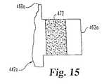
上記服用量表示装置において、上記確認器が、薬剤の濃度を代表する、寸法的な様相と、空間的な様相と、を有する単一バンドから構成されている。
上記服用量表示装置において、上記単一バンドが導電性であり、上記コンテナー認識器が複数の電気接点を含んでおり、上記複数の電気接点の異なる組合せが、異なる薬剤濃度で満たされたコンテナーの単一バンドによって一緒に配線されている。
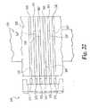
上記服用量表示装置において、上記マトリックスが、第1構成要素の外周周りに延びる複数の列と、第1要素の軸方向長さに沿い延びる複数のコラムと、を備えている。
上記服用量表示装置において、上記複数のコラムが、24個のコラムを包含している。
上記服用量表示装置において、上記センサーアレーが複数の電気接点を含有しており、上記接点の各々が上記マトリックスの異なる列と整合しており、上記マトリックスデータが上記マトリックスの上記列とコラムとの交点における導電材料の有無の形式のデータであり、上記センサーアレーに対する上記回転可能マトリックスの異なる回転位置のために、上記複数の電気接点の異なる組合せが、導電材料の存在によって形成されるマトリックスデータによって、一緒に配線されている。
上記服用量表示装置において、服用量セッテイング機構の調整中に、上記第1構成要素が、上記第2構成要素に対して軸方向に固定される。
上記服用量表示装置において、上記センサーアレーと上記回転可能マトリックスとが、協働可能に形成され、これによって上記マトリックスデータが接地されている隣接列間で上記センサーアレーの上記回転可能マトリックスに対する何らかの回動が上記マトリックスデータ付き電気回路との単一な電気接点切換を起すようになっている。
上記服用量表示装置において、上記マトリックスデータの全ての上記導電材料が、接触している。(Outline of the Invention)
A therapeutic dose display device according to the present invention is a therapeutic dose display device for a portable drug injection device containing an adjustable dose setting mechanism, the portable drug injection device. Is equipped with a removable drug container, which contains a visible display and a container recognizer for recognizing the drug concentration in the container, the container recognizer being located on the container, A container recognizer, a dose confirmer that recognizes the amount of drug selected for release by an adjustable dose setting mechanism, and a therapeutic dose based on the recognized concentration and the confirmed amount A controller adapted to determine a therapeutic dose such that a therapeutic dose is displayed within the visible display; and And the dose checker includes a rotatable matrix and a sensor array adapted to confirm data contained within the matrix, the rotatable matrix and the A sensor array is mounted on each of the first and second components of the drug injection device, both of which rotate relative to each other during adjustment of the dose setting mechanism.
In the dose display device, the container includes a cartridge assembly, the cartridge assembly contains a cartridge connectable to the reusable base of the injection device in the outer housing, and the checker is Arranged on the outer housing.
In the dose display device, the outer housing contains a reduced-diameter hub adjusted to the length of the cartridge, the checker is disposed thereon, and the hub is reusable for an injection device. Fits within the base.
In the dose display device, the confirmation device is composed of a single band having a dimensional aspect and a spatial aspect representative of the concentration of the drug.
In the dose display device, the single band is conductive, the container recognizer includes a plurality of electrical contacts, and different combinations of the plurality of electrical contacts are filled with different drug concentrations. Wired together by a single band.
In the dose display device, the matrix includes a plurality of rows extending around the outer periphery of the first component, and a plurality of columns extending along the axial length of the first element.
In the dose display device, the plurality of columns includes 24 columns.
In the dose display device, the sensor array includes a plurality of electrical contacts, each of the contacts is aligned with a different column of the matrix, and the matrix data is defined between the columns and columns of the matrix. Data in the form of the presence or absence of a conductive material at the intersection, and because of the different rotational positions of the rotatable matrix relative to the sensor array, different combinations of the plurality of electrical contacts may depend on the matrix data formed by the presence of the conductive material. Are wired together.
In the dose display device, the first component is fixed axially with respect to the second component during adjustment of the dose setting mechanism.
In the dose display device, the sensor array and the rotatable matrix are formed so as to be able to cooperate with each other, so that any rotation of the sensor array relative to the rotatable matrix is performed between adjacent columns to which the matrix data is grounded. The movement causes a single electric contact switching with the electric circuit with matrix data.
In the dose display device, all the conductive materials of the matrix data are in contact.
本発明に係る服用可能量確認器は、保持されているカートリッジから放出される薬剤量を選択するように作動可能な服用量セッテイング機構を有する薬物注射装置のための服用可能量確認器であって、装置の第1構成要素上に配置された回転可能マトリックスと、回転可能マトリックスの電気的感知のためのセンサーであって、上記センサーが服用量セッテイング機構の作動中に第1構成要素に対する回転を経験する装置の第2構成要素上に配置されている、センサーと、を包含しており、これによって、上記マトリックスセンサーによって感知可能な、上記回転可能なマトリックスのデータが、服用量セッテイング機構の位置を表示可能であり、上記センサーと配線されたコントローラーであって、上記センサーにより感知された上記回転可能マトリックスのデータを注射中にカートリッジから放出されるべき薬剤量を決定するように翻訳処理するコントローラーと、上記コントローラーによって決定されたように放出されるべき薬剤量を表示する可視可能なディスプレーと、を包含しており、上記マトリックスが第1構成要素の外周周りに延びる複数個の列、および第1構成要素の軸方向長さに沿い延びる複数個のコラムを含有している。A dose confirmation device according to the present invention is a dose confirmation device for a drug injection device having a dose setting mechanism operable to select the amount of a drug released from a held cartridge. A rotatable matrix disposed on the first component of the device and a sensor for electrical sensing of the rotatable matrix, wherein the sensor rotates relative to the first component during operation of the dose setting mechanism. A sensor disposed on a second component of the device to be experienced, whereby the rotatable matrix data sensed by the matrix sensor is a position of the dose setting mechanism. A controller wired with the sensor, the rotation sensed by the sensor A controller that translates the performance matrix data to determine the amount of drug to be released from the cartridge during injection; a visible display that displays the amount of drug to be released as determined by the controller; The matrix includes a plurality of rows extending around the outer periphery of the first component and a plurality of columns extending along the axial length of the first component.
上記服用可能量確認器において、上記複数個のコラムが24個のコラムを含んでいる。In the dose confirmation device, the plurality of columns include 24 columns.
上記服用可能量確認器において、上記センサーは複数個の電気接点を含有しており、各接点は上記マトリックスの異なる列と整列され、かつ上記マトリックスデータが、上記マトリックスの上記列とコラムとの交点における導電材料の有無の形式のデータである。In the dose enabler, the sensor includes a plurality of electrical contacts, each contact is aligned with a different column of the matrix, and the matrix data is an intersection of the column and column of the matrix. It is the data of the format of the presence or absence of the electrically-conductive material in.
本発明に係る服用可能量確認器は、保持されているカートリッジから放出される薬剤量を選択するように作動可能な服用量セッテイング機構を有する薬物注射装置のための服用可能量確認器であって、装置の第1構成要素上に配置された回転可能マトリックスと、回転可能マトリックスの電気的感知のためのセンサーであって、上記センサーが服用量セッテイング機構の作動中に第1構成要素に対する回転を経験する装置の第2構成要素上に配置されている、センサーと、を包含しており、これによって、上記マトリックスセンサーによって感知可能な、上記回転可能なマトリックスのデータが、服用量セッテイング機構の位置を表示可能であり、上記センサーと配線されたコントローラーであって、上記センサーにより感知された上記回転可能マトリックスのデータを注射中にカートリッジから放出されるべき薬剤量を決定するように翻訳処理するコントローラーと、上記コントローラーによって決定されたように放出されるべき薬剤量を表示する可視可能なディスプレーと、を包含しており、上記回転可能マトリックスのデータが、第2構成要素に対する第1構成要素の各セッテイング可能回転配置のための唯一のものである。A dose confirmation device according to the present invention is a dose confirmation device for a drug injection device having a dose setting mechanism operable to select the amount of a drug released from a held cartridge. A rotatable matrix disposed on the first component of the device and a sensor for electrical sensing of the rotatable matrix, wherein the sensor rotates relative to the first component during operation of the dose setting mechanism. A sensor disposed on a second component of the device to be experienced, whereby the rotatable matrix data sensed by the matrix sensor is a position of the dose setting mechanism. A controller wired with the sensor, the rotation sensed by the sensor A controller that translates the performance matrix data to determine the amount of drug to be released from the cartridge during injection; a visible display that displays the amount of drug to be released as determined by the controller; The rotatable matrix data is unique for each settable rotatable arrangement of the first component relative to the second component.
本発明に係る服用可能量確認器は、保持されているカートリッジから放出される薬剤量を選択するように作動可能な服用量セッテイング機構を有する薬物注射装置のための服用可能量確認器であって、装置の第1構成要素上に配置された回転可能マトリックスと、回転可能マトリックスの電気的感知のためのセンサーであって、上記センサーが服用量セッテイング機構の作動中に第1構成要素に対する回転を経験する装置の第2構成要素上に配置されている、センサーと、を包含しており、これによって、上記マトリックスセンサーによって感知可能な、上記回転可能なマトリックスのデータが、服用量セッテイング機構の位置を表示可能であり、上記センサーと配線されたコントローラーであって、上記センサーにより感知された上記回転可能マトリックスのデータを注射中にカートリッジから放出されるべき薬剤量を決定するように翻訳処理するコントローラーと、上記コントローラーによって決定されたように放出されるべき薬剤量を表示する可視可能なディスプレーと、を包含しており、上記回転可能マトリックスデータが、グレーコードコーデイング組織を含んでいる。A dose confirmation device according to the present invention is a dose confirmation device for a drug injection device having a dose setting mechanism operable to select the amount of a drug released from a held cartridge. A rotatable matrix disposed on the first component of the device and a sensor for electrical sensing of the rotatable matrix, wherein the sensor rotates relative to the first component during operation of the dose setting mechanism. A sensor disposed on a second component of the device to be experienced, whereby the rotatable matrix data sensed by the matrix sensor is a position of the dose setting mechanism. A controller wired with the sensor, the rotation sensed by the sensor A controller that translates the performance matrix data to determine the amount of drug to be released from the cartridge during injection, and a visible display that displays the amount of drug to be released as determined by the controller; And the rotatable matrix data includes a Gray code coding structure.
上記服用可能量確認器において、更に上記マトリックスの同じ列と整列する余分の電気接点を上記複数個の電気接点の一つとして包含している。The dose checker further includes an extra electrical contact aligned with the same column of the matrix as one of the plurality of electrical contacts.
本発明に係る服用可能量確認器は、保持されているカートリッジから放出される薬剤量を選択するように作動可能な服用量セッテイング機構を有する薬物注射装置のための服用可能量確認器であって、装置の第1構成要素上に配置された回転可能マトリックスと、回転可能マトリックスの電気的感知のためのセンサーであって、上記センサーが服用量セッテイング機構の作動中に第1構成要素に対する回転を経験する装置の第2構成要素上に配置されている、センサーと、を包含しており、これによって、上記マトリックスセンサーによって感知可能な、上記回転可能なマトリックスのデータが、服用量セッテイング機構の位置を表示可能であり、上記センサーと配線されたコントローラーであって、上記センサーにより感知された上記回転可能マトリックスのデータを注射中にカートリッジから放出されるべき薬剤量を決定するように翻訳処理するコントローラーと、上記コントローラーによって決定されたように放出されるべき薬剤量を表示する可視可能なディスプレーと、を包含しており、上記マトリックスが、複数個の列および複数個のコラムを含有しており、上記センサーが、複数個の電気接点を含有しており、上記接点の各々が、上記マトリックスの異なる列と整列しており、上記マトリックスデータが、上記マトリックスの上記列とコラムとの交点における導電材料の有無の形式のデータであり、かつ上記複数個の電気接点と上記回転可能マトリックスとが、協働可能に形成されて第1、第2構成要素が、第1回転位置から相対的に回転シフトされると、いずれかの単一電気接点により感知されたマトリックスデータ内の変化が第1回転位置から離れた各々の回転位置のレンジ内の回転位置に対応するパターンを作らず、上記レンジは2および少なくとも3位置を含むものである。A dose confirmation device according to the present invention is a dose confirmation device for a drug injection device having a dose setting mechanism operable to select the amount of a drug released from a held cartridge. A rotatable matrix disposed on the first component of the device and a sensor for electrical sensing of the rotatable matrix, wherein the sensor rotates relative to the first component during operation of the dose setting mechanism. A sensor disposed on a second component of the device to be experienced, whereby the rotatable matrix data sensed by the matrix sensor is a position of the dose setting mechanism. A controller wired with the sensor, the rotation sensed by the sensor A controller that translates the performance matrix data to determine the amount of drug to be released from the cartridge during injection; a visible display that displays the amount of drug to be released as determined by the controller; The matrix includes a plurality of rows and a plurality of columns, the sensor includes a plurality of electrical contacts, and each of the contacts is different from the matrix. The matrix data is in the form of the presence or absence of a conductive material at the intersection of the row and column of the matrix, and the plurality of electrical contacts and the rotatable matrix cooperate. When the first and second components are formed so as to be operable and are relatively rotationally shifted from the first rotational position, Change in the matrix data sensed by first electrical contact is not made a pattern corresponding to the rotational position within the range of the rotational position of each remote from the first rotational position, the range is intended to include 2 and at least 3 positions.
上記服用可能量確認器において、上記少なくとも3位置が、6位置である。In the dose confirmation device, the at least 3 positions are 6 positions.
本発明に係る服用可能量確認器は、保持されているカートリッジから放出される薬剤量を選択するように作動可能な服用量セッテイング機構を有する薬物注射装置のための服用可能量確認器であって、装置の第1構成要素上に配置された回転可能マトリックスと、回転可能マトリックスの電気的感知のためのセンサーであって、上記センサーが服用量セッテイング機構の作動中に第1構成要素に対する回転を経験する装置の第2構成要素上に配置されている、センサーと、を包含しており、これによって、上記マトリックスセンサーによって感知可能な、上記回転可能なマトリックスのデータが、服用量セッテイング機構の位置を表示可能であり、上記センサーと配線されたコントローラーであって、上記センサーにより感知された上記回転可能マトリックスのデータを注射中にカートリッジから放出されるべき薬剤量を決定するように翻訳処理するコントローラーと、上記コントローラーによって決定されたように放出されるべき薬剤量を表示する可視可能なディスプレーと、を包含しており、上記マトリックスが、複数個の列および複数個のコラムを含有しており、上記センサーが、複数個の電気接点を含有しており、上記接点の各々が、上記マトリックスの異なる列に整列しており、上記マトリックスデータが、上記マトリックスの上記列とコラムとの交点における導電材料の有無の形式のデータであり、上記複数の電気接点と上記回転可能マトリックスとが、上記マトリックスの各コラムのマトリックスデータが唯一ではないように協働可能に形成されており、上記コントローラーが、第1、第2構成要素の正しい相対的回転位置をそれらの以前の有効な位置および両側における上記以前の有効な位置に近接した位置レンジに基づいて確認するように適合されている。A dose confirmation device according to the present invention is a dose confirmation device for a drug injection device having a dose setting mechanism operable to select the amount of a drug released from a held cartridge. A rotatable matrix disposed on the first component of the device and a sensor for electrical sensing of the rotatable matrix, wherein the sensor rotates relative to the first component during operation of the dose setting mechanism. A sensor disposed on a second component of the device to be experienced, whereby the rotatable matrix data sensed by the matrix sensor is a position of the dose setting mechanism. A controller wired with the sensor, the rotation sensed by the sensor A controller that translates the performance matrix data to determine the amount of drug to be released from the cartridge during injection; a visible display that displays the amount of drug to be released as determined by the controller; The matrix includes a plurality of rows and a plurality of columns, the sensor includes a plurality of electrical contacts, and each of the contacts is different from the matrix. The matrix data is data in the form of the presence or absence of conductive material at the intersections of the columns and columns of the matrix, and the plurality of electrical contacts and the rotatable matrix are in the matrix. The matrix data of each column is formed to be collaborative so that it is not unique. Ra is, first, is adapted to check based on the correct relative rotational position of the second component in the position range in proximity to a valid position of the previous in a previous valid position and on both sides thereof.
本発明に係る服用可能量確認器は、保持されているカートリッジから放出される薬剤量を選択するように作動可能な服用量セッテイング機構を有する薬物注射装置のための服用可能量確認器であって、装置の第1構成要素上に配置された回転可能マトリックスと、回転可能マトリックスの電気的感知のためのセンサーであって、上記センサーが服用量セッテイング機構の作動中に第1構成要素に対する回転を経験する装置の第2構成要素上に配置されている、センサーと、を包含しており、これによって、上記マトリックスセンサーによって感知可能な、上記回転可能なマトリックスのデータが、服用量セッテイング機構の位置を表示可能であり、上記センサーと配線されたコントローラーであって、上記センサーにより感知された上記回転可能マトリックスのデータを注射中にカートリッジから放出されるべき薬剤量を決定するように翻訳処理するコントローラーと、上記コントローラーによって決定されたように放出されるべき薬剤量を表示する可視可能なディスプレーと、を包含しており、上記マトリックスが、複数個の列および複数個のコラムを含有しており、上記センサーが、複数個の電気接点を含有しており、上記接点の各々が、上記マトリックスの異なる列に整列しており、上記マトリックスデータが、上記マトリックスの上記列とコラムとの交点における導電材料の有無の形式のデータであり、上記複数の電気接点と上記回転マトリックスとが、協働可能に形成されており、これによってマトリックスデータに対するロジックハイまたは接地入力が一定に残っている隣接コラム間の第1、第2要素の何れかの相対的なシフトが、上記複数の電気接点の2個のマトリックスデータとの正確な電気回路関係の切換えを起すようになっている。A dose confirmation device according to the present invention is a dose confirmation device for a drug injection device having a dose setting mechanism operable to select the amount of a drug released from a held cartridge. A rotatable matrix disposed on the first component of the device and a sensor for electrical sensing of the rotatable matrix, wherein the sensor rotates relative to the first component during operation of the dose setting mechanism. A sensor disposed on a second component of the device to be experienced, whereby the rotatable matrix data sensed by the matrix sensor is a position of the dose setting mechanism. A controller wired with the sensor, the rotation sensed by the sensor A controller that translates the performance matrix data to determine the amount of drug to be released from the cartridge during injection; a visible display that displays the amount of drug to be released as determined by the controller; The matrix includes a plurality of rows and a plurality of columns, the sensor includes a plurality of electrical contacts, and each of the contacts is different from the matrix. The matrix data is data in the form of the presence or absence of a conductive material at the intersection between the column and the column of the matrix, and the plurality of electrical contacts and the rotation matrix can cooperate with each other. This ensures that the logic high or ground input for the matrix data remains constant. First between adjacent columns, any relative shift of the second element is adapted to cause switching of precise electric circuit relation between the two matrix data of the plurality of electrical contacts.
本発明に係る服用量の表示方法は、薬剤カートリッジを搭載した携帯式薬物注射装置のユーザーに対する治療上服用量の表示方法であって、薬物注射装置が薬剤放出量選択のための服用量セッテイング機構を備えたものにおいて、携帯式薬物注射装置のカートリッジ認識器でカートリッジ内の薬剤濃度を認識する工程と、携帯式薬物注射装置の服用可能量確認器で選択された放出量を確認する工程と、認識された濃度および確認された選択放出量を入力として利用して携帯式薬物注射装置のコントローラーで治療上服用量を決定する工程と、携帯式薬物注射装置のディスプレー上に決定された治療上服用量をディスプレーする工程と、を含んでおり、上記服用可能量確認器が、回転可能なマトリックスと、上記マトリックス内に含有されたデータを確認するようにされたセンサーアレーと、を含有しており、上記回転可能マトリックスと上記センサーアレーとが、各々上記薬物注射装置の第1、第2構成要素上に装着され、両要素が、服用量セッテイング機構の調整中に互いに回転する。A dose display method according to the present invention is a therapeutic dose display method for a user of a portable drug injection device equipped with a drug cartridge, and the drug injection device is a dose setting mechanism for selecting a drug release amount. The step of recognizing the drug concentration in the cartridge with the cartridge recognizing device of the portable drug injection device, the step of checking the release amount selected with the dose confirmation device of the portable drug injection device, Determining the therapeutic dose at the controller of the portable drug injection device using the recognized concentration and the confirmed selective release as input, and the therapeutic dose determined on the display of the portable drug injection device A dose display comprising: a rotatable matrix; a matrix contained in the matrix; A sensor array adapted to identify a sensor, wherein the rotatable matrix and the sensor array are mounted on first and second components of the drug injection device, respectively, Rotate each other during adjustment of the dose setting mechanism.
上記服用量の表示方法において、カートリッジ認識器が、カートリッジ上の濃度認識器および薬物注射装置内の認識センサーを含有している。In the dose display method, the cartridge recognizer includes a concentration recognizer on the cartridge and a recognition sensor in the drug injection device.
上記服用量の表示方法において、更にカートリッジ認識器がカートリッジ内の薬剤濃度の認識不能となった時にコントローラーに対して濃度量をインプットするためのユーザー手動のセットボタン付きの薬物注射装置を提供する工程を包含し、コントローラーは認識された選択放出量付きの手動インプット濃度量を治療上服用量決定用インプットとして使用する。In the above dose display method, a step of providing a drug injection device with a user manual set button for inputting a concentration amount to the controller when the cartridge recognizer becomes unable to recognize the drug concentration in the cartridge. And the controller uses the recognized amount of manual input concentration with selective release as the input for therapeutic dose determination.
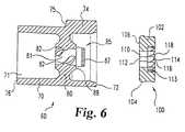
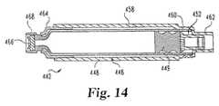
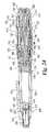
本発明に係る薬物注射装置は、薬物注射装置であって、ハウジングと、上記ハウジングに装着された流体コンテナーであって、上記流体コンテナーが薬剤充満のリザーバーを区画しかつ上記リザーバーの基端部が可動ピストンを備えている、流体コンテナーと、上記流体コンテナーの先端部に取り外し可能に装着された針アセンブリーであって、上記リザーバーと流れ連通状態の上記針アセンブリーの注射針が装着されている、針アセンブリーと、上記ハウジング内で先端方向へ前進可能な駆動部材であって、上記ピストンを上記注射針方向へ動かして上記コンテナーから薬剤を加圧するようにされた駆動部材と、服用量セッテイング要素であって、上記ハウジング外における制御部分を備えかつ上記服用量セッテイング要素を引っ込められた位置から突っ込み可能位置へと捩る第1方向へ手動回転可能であり、上記突っ込み可能位置では上記服用量セッテイング要素は上記引っ込められた位置から上記ハウジングから更に基端側へ突出する、服用量セッテイング要素と、上記駆動部材を上記先端方向へ前進させるために、上記服用量セッテイング要素を上記突っ込み可能位置から上記引っ込められた位置へ回転させることなく移すことによって操作可能な手段であって、上記前進手段は駆動スリーブおよび上記ハウジング内のバレルを包含し、上記服用量セッテイング要素の上記引っ込められた位置と上記突っ込み可能位置との間における上記服用量セッテイング要素の動きの少なくとも一部の間で相対的な回転を行う、手段と、上記バレルおよび上記駆動スリーブの相対回転位置の検知に基づいて注射されるべき薬剤の服用量をディスプレーする電子アセンブリーと、を含んでおり、上記バレルと上記駆動スリーブとが、上記ハウジング内で第1軸方向位置から第2軸方向位置へ回転することなく移動し、その際上記服用量セッテイング要素は上記突っ込み可能位置から上記引っ込められた位置への移行の一部の間で回転することなく移動し、かつ上記電子アセンブリーが、スイッチを含有しており、該スイッチが、上記バレルと上記スリーブとが上記第1軸方向位置から第2軸方向位置へ移行する際に起動されて、これによって装置が服用モードから注射モードへの移行を発信し、上記服用量セッテイング要素の上記移行部分が、上記突っ込み可能位置から始まる。A drug injection device according to the present invention is a drug injection device, which is a housing and a fluid container attached to the housing, wherein the fluid container defines a drug-filled reservoir, and a proximal end portion of the reservoir is A fluid container having a movable piston and a needle assembly removably attached to a tip of the fluid container, the needle being attached to the needle assembly in flow communication with the reservoir An assembly, a drive member capable of advancing in a distal direction within the housing, wherein the drive member is configured to pressurize the drug from the container by moving the piston in the direction of the injection needle; and a dose setting element. With a control part outside the housing and withdrawing the dose setting element A dose setting element that is manually rotatable in a first direction twisting from a position into a pushable position, wherein the dose setting element projects further from the housing further proximally from the retracted position; And a means operable to move the dose setting element from the retractable position to the retracted position without rotating in order to advance the drive member in the distal direction, Includes a drive sleeve and a barrel within the housing, relative to at least a portion of the movement of the dose setting element between the retracted position and the retractable position of the dose setting element. Means for performing rotation and relative rotational position of the barrel and the drive sleeve; An electronic assembly for displaying a dose of drug to be injected based on the detection of the barrel, and the barrel and the drive sleeve from a first axial position to a second axial position in the housing. Moves without rotation, wherein the dose setting element moves without rotation during a portion of the transition from the retractable position to the retracted position, and the electronic assembly includes a switch. And the switch is activated when the barrel and the sleeve transition from the first axial position to the second axial position, thereby causing the device to signal a transition from the dosing mode to the injection mode. The transition portion of the dose setting element then begins at the pushable position.
本発明に係る薬物注射装置は、薬物注射装置であって、ハウジングと、上記ハウジングに装着された流体コンテナーであって、上記流体コンテナーが薬剤充満のリザーバーを区画しかつ上記リザーバーの基端部が可動ピストンを備えている、流体コンテナーと、上記流体コンテナーの先端部に取り外し可能に装着された針アセンブリーであって、上記リザーバーと流れ連通状態の上記針アセンブリーの注射針が装着されている、針アセンブリーと、上記ハウジング内で先端方向へ前進可能な駆動部材であって、上記ピストンを上記注射針方向へ動かして上記コンテナーから薬剤を加圧するようにされた駆動部材と、服用量セッテイング要素であって、上記ハウジング外における制御部分を備えかつ上記服用量セッテイング要素を引っ込められた位置から突っ込み可能位置へと捩る第1方向へ手動回転可能であり、上記突っ込み可能位置では上記服用量セッテイング要素は上記引っ込められた位置から上記ハウジングから更に基端側へ突出する、服用量セッテイング要素と、上記駆動部材を上記先端方向へ前進させるために、上記服用量セッテイング要素を上記突っ込み可能位置から上記引っ込められた位置へ回転させることなく移すことによって操作可能な手段であって、上記前進手段は駆動スリーブおよび上記ハウジング内のバレルを包含し、上記服用量セッテイング要素の上記引っ込められた位置と上記突っ込み可能位置との間における上記服用量セッテイング要素の動きの少なくとも一部の間で相対的な回転を行う、手段と、上記バレルおよび上記駆動スリーブの相対回転位置の検知に基づいて注射されるべき薬剤の服用量をディスプレーする電子アセンブリーと、を含んでおり、上記バレルと上記駆動スリーブとが、上記ハウジング内で第1軸方向位置から第2軸方向位置へ回転することなく移動し、その際上記服用量セッテイング要素は上記突っ込み可能位置から上記引っ込められた位置への移行の一部の間で回転することなく移動し、かつ上記電子アセンブリーが、スイッチを含有しており、該スイッチが、上記バレルと上記スリーブとが上記第1軸方向位置から第2軸方向位置へ移行する際に起動されて、これによって装置が服用モードから注射モードへの移行を発信する、上記駆動スリーブが、上記服用量セッテイング要素との直接的係合によって上記第1軸方向位置から上記第2軸方向位置へ動かされ、上記駆動スリーブは衝合面を備え、上記バレルは上記駆動スリーブ衝合面により直接的に接触されて上記バレルを上記第1軸方向位置から上記第2軸方向位置へ動かすための面を含有している。A drug injection device according to the present invention is a drug injection device, which is a housing and a fluid container attached to the housing, wherein the fluid container defines a drug-filled reservoir, and a proximal end portion of the reservoir is A fluid container having a movable piston and a needle assembly removably attached to a tip of the fluid container, the needle being attached to the needle assembly in flow communication with the reservoir An assembly, a drive member capable of advancing in a distal direction within the housing, wherein the drive member is configured to pressurize the drug from the container by moving the piston in the direction of the injection needle; and a dose setting element. With a control part outside the housing and withdrawing the dose setting element A dose setting element that is manually rotatable in a first direction twisting from a position into a pushable position, wherein the dose setting element projects further from the housing further proximally from the retracted position; And a means operable to move the dose setting element from the retractable position to the retracted position without rotating in order to advance the drive member in the distal direction, Includes a drive sleeve and a barrel within the housing, relative to at least a portion of the movement of the dose setting element between the retracted position and the retractable position of the dose setting element. Means for performing rotation and relative rotational position of the barrel and the drive sleeve; An electronic assembly for displaying a dose of drug to be injected based on the detection of the barrel, and the barrel and the drive sleeve from a first axial position to a second axial position in the housing. Moves without rotation, wherein the dose setting element moves without rotation during a portion of the transition from the retractable position to the retracted position, and the electronic assembly includes a switch. And the switch is activated when the barrel and the sleeve transition from the first axial position to the second axial position, thereby causing the device to signal a transition from the dosing mode to the injection mode. The drive sleeve is moved from the first axial position to the second axial position by direct engagement with the dose setting element; The drive sleeve includes an abutment surface, and the barrel includes a surface that is directly contacted by the drive sleeve abutment surface to move the barrel from the first axial position to the second axial position. ing.
上記薬物注射装置において、上記駆動スリーブ衝合面によって直接接触される上記バレル面が、上記バレルの半径方向内方突出リップの基端面を含んでおり、上記リップの先端面が、複数個のスプラインを含有しており、該スプラインが、上記バレルが上記第2軸方向位置内に配置された時におけるバレルの回転阻止のために、上記ハウジングのスプラインの切られた隔壁に噛合している。In the drug injection device, the barrel surface directly contacted by the drive sleeve abutting surface includes a proximal end surface of a radially inward projecting lip of the barrel, and a distal end surface of the lip includes a plurality of splines. The spline engages a splined partition of the housing to prevent rotation of the barrel when the barrel is positioned in the second axial position.
本発明に係る薬物注射装置は、薬物注射装置であって、ハウジングと、上記ハウジングに装着された流体コンテナーであって、上記流体コンテナーが薬剤充満のリザーバーを区画しかつ上記リザーバーの基端部が可動ピストンを備えている、流体コンテナーと、上記流体コンテナーの先端部に取り外し可能に装着された針アセンブリーであって、上記リザーバーと流れ連通状態の上記針アセンブリーの注射針が装着されている、針アセンブリーと、上記ハウジング内で先端方向へ前進可能な駆動部材であって、上記ピストンを上記注射針方向へ動かして上記コンテナーから薬剤を加圧するようにされた駆動部材と、服用量セッテイング要素であって、上記ハウジング外における制御部分を備えかつ上記服用量セッテイング要素を引っ込められた位置から突っ込み可能位置へと捩る第1方向へ手動回転可能であり、上記突っ込み可能位置では上記服用量セッテイング要素は上記引っ込められた位置から上記ハウジングから更に基端側へ突出する、服用量セッテイング要素と、上記駆動部材を上記先端方向へ前進させるために、上記服用量セッテイング要素を上記突っ込み可能位置から上記引っ込められた位置へ回転させることなく移すことによって操作可能な手段であって、上記前進手段は駆動スリーブおよび上記ハウジング内のバレルを包含し、上記服用量セッテイング要素の上記引っ込められた位置と上記突っ込み可能位置との間における上記服用量セッテイング要素の動きの少なくとも一部の間で相対的な回転を行う、手段と、上記バレルおよび上記駆動スリーブの相対回転位置の検知に基づいて注射されるべき薬剤の服用量をディスプレーする電子アセンブリーと、を含んでおり、上記バレルと上記駆動スリーブとが、上記ハウジング内で第1軸方向位置から第2軸方向位置へ回転することなく移動し、その際上記服用量セッテイング要素は上記突っ込み可能位置から上記引っ込められた位置への移行の一部の間で回転することなく移動し、かつ上記電子アセンブリーが、スイッチを含有しており、該スイッチが、上記バレルと上記スリーブとが上記第1軸方向位置から第2軸方向位置へ移行する際に起動されて、これによって装置が服用モードから注射モードへの移行を発信する、A drug injection device according to the present invention is a drug injection device, which is a housing and a fluid container attached to the housing, wherein the fluid container defines a drug-filled reservoir, and a proximal end portion of the reservoir is A fluid container having a movable piston and a needle assembly removably attached to a tip of the fluid container, the needle being attached to the needle assembly in flow communication with the reservoir An assembly, a drive member capable of advancing in a distal direction within the housing, wherein the drive member is configured to pressurize the drug from the container by moving the piston in the direction of the injection needle; and a dose setting element. With a control part outside the housing and withdrawing the dose setting element A dose setting element that is manually rotatable in a first direction twisting from a position into a pushable position, wherein the dose setting element projects further from the housing further proximally from the retracted position; And a means operable to move the dose setting element from the retractable position to the retracted position without rotating in order to advance the drive member in the distal direction, Includes a drive sleeve and a barrel within the housing, relative to at least a portion of the movement of the dose setting element between the retracted position and the retractable position of the dose setting element. Means for performing rotation and relative rotational position of the barrel and the drive sleeve; An electronic assembly for displaying a dose of drug to be injected based on the detection of the barrel, and the barrel and the drive sleeve from a first axial position to a second axial position in the housing. Moves without rotation, wherein the dose setting element moves without rotation during a part of the transition from the retractable position to the retracted position, and the electronic assembly includes a switch. And the switch is activated when the barrel and the sleeve transition from the first axial position to the second axial position, thereby causing the device to signal a transition from the dosing mode to the injection mode. To
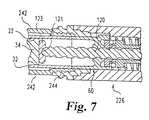
上記スイッチが、上記バレルと軸方向摺動不能かつ回転可能にキー止めされたスライダー要素上に装着されている。The switch is mounted on a slider element that is axially non-slidable and rotatable with the barrel.
上記薬物注射装置において、上記スライダー要素が、上記バレルの外面内に形成されている少なくとも1個の円周溝内でスライドする少なくとも1個の半径方向内方に突出したキーを含有している。In the drug injection device, the slider element contains at least one radially inwardly projecting key that slides in at least one circumferential groove formed in the outer surface of the barrel.
上記薬物注射装置において、上記スライダー要素が、上記ハウジングに回転可能に、かつ軸方向移動可能に、キー止めされ、かつ上記スイッチが、上記ハウジングの機構に付勢係合することによって電気回路を完全に閉じることにより起動される。In the drug injection device, the slider element is keyed to be rotatable and axially movable on the housing, and the switch is biased to engage with the mechanism of the housing to complete the electric circuit. It is started by closing.
本発明に係る薬物注射装置は、薬物注射装置であって、ハウジングと、上記ハウジングに装着された流体コンテナーであって、上記流体コンテナーが薬剤充満のリザーバーを区画しかつ上記リザーバーの基端部が可動ピストンを備えている、流体コンテナーと、上記流体コンテナーの先端部に取り外し可能に装着された針アセンブリーであって、上記リザーバーと流れ連通状態の上記針アセンブリーの注射針が装着されている、針アセンブリーと、上記ハウジング内で先端方向へ前進可能な駆動部材であって、上記ピストンを上記注射針方向へ動かして上記コンテナーから薬剤を加圧するようにされた駆動部材と、服用量セッテイング要素であって、上記ハウジング外における制御部分を備えかつ上記服用量セッテイング要素を引っ込められた位置から突っ込み可能位置へと捩る第1方向へ手動回転可能であり、上記突っ込み可能位置では上記服用量セッテイング要素は上記引っ込められた位置から上記ハウジングから更に基端側へ突出する、服用量セッテイング要素と、上記駆動部材を上記先端方向へ前進させるために、上記服用量セッテイング要素を上記突っ込み可能位置から上記引っ込められた位置へ回転させることなく移すことによって操作可能な手段であって、上記前進手段は駆動スリーブおよび上記ハウジング内のバレルを包含し、上記服用量セッテイング要素の上記引っ込められた位置と上記突っ込み可能位置との間における上記服用量セッテイング要素の動きの少なくとも一部の間で相対的な回転を行う、手段と、上記バレルおよび上記駆動スリーブの相対回転位置の検知に基づいて注射されるべき薬剤の服用量をディスプレーする電子アセンブリーと、を含んでおり、上記服用量セッテイング要素が、上記ハウジング内のバレルと、上記バレルに対して軸方向移行可能かつ回転可能にキー止めされており、かつ上記服用量セッテイング要素が、上記駆動スリーブのねじと噛合する内面から半径方向内側へ突出したねじと、を備えている。A drug injection device according to the present invention is a drug injection device, which is a housing and a fluid container attached to the housing, wherein the fluid container defines a drug-filled reservoir, and a proximal end portion of the reservoir is A fluid container having a movable piston and a needle assembly removably attached to a tip of the fluid container, the needle being attached to the needle assembly in flow communication with the reservoir An assembly, a drive member capable of advancing in a distal direction within the housing, wherein the drive member is configured to pressurize the drug from the container by moving the piston in the direction of the injection needle; and a dose setting element. With a control part outside the housing and withdrawing the dose setting element A dose setting element that is manually rotatable in a first direction twisting from a position into a pushable position, wherein the dose setting element projects further from the housing further proximally from the retracted position; And a means operable to move the dose setting element from the retractable position to the retracted position without rotating in order to advance the drive member in the distal direction, Includes a drive sleeve and a barrel within the housing, relative to at least a portion of the movement of the dose setting element between the retracted position and the retractable position of the dose setting element. Means for performing rotation and relative rotational position of the barrel and the drive sleeve; An electronic assembly for displaying a dose of a drug to be injected based on the detection of the barrel, wherein the dose setting element is axially translatable and rotatable relative to the barrel within the housing The dose setting element includes a screw that is keyed so as to protrude radially inward from an inner surface that meshes with a screw of the drive sleeve.
上記薬物注射装置において、上記前進手段が、上記服用量セッテイング要素が突っ込み得る位置から上記引っ込められた位置へ回転せずに移行すると、次の服用のために上記服用量セッテイング要素を自動的にリセットする。In the drug injection device, the advancement means automatically resets the dose setting element for the next dose when transitioning from the position where the dose setting element can be pushed into the retracted position without rotating. To do.
上記薬物注射装置において、上記バレルと上記駆動スリーブとが、上記服用量セッテイング要素が上記突っ込み得る位置から上記引っ込められた位置への移行行程の一部の間で回転することなく移行すると、上記ハウジング内で第1軸方向位置から第2軸方向位置へ回転することなく先端側へ移行し、かつ更に上記ハウジングに対する上記バレルの回転を防止し、かつ上記バレルと駆動スリーブとが、上記第2軸方向位置に配置されている時上記駆動スリーブの更なる先端側への動きを停止して、これにより上記行程部分および上記引っ込められた位置への動きが上記駆動スリーブを回した後における上記服用量セッテイング要素の軸方向移行を停止する手段を包含している。In the drug injection device, when the barrel and the drive sleeve transition without rotating during a part of the transition process from the position where the dose setting element can be pushed into the retracted position, the housing Without moving from the first axial position to the second axial position, and further preventing rotation of the barrel relative to the housing, and the barrel and the drive sleeve are connected to the second shaft. Stops further movement of the drive sleeve toward the distal end when placed in a directional position, so that the dose after the stroke portion and movement to the retracted position turn the drive sleeve Means are included for stopping the axial transition of the setting element.
上記薬物注射装置において、上記駆動スリーブの上記ねじが外面周りを螺旋状に延びるスロットを包含している。In the drug injection device, the screw of the drive sleeve includes a slot extending helically around an outer surface.
本発明に係る薬物注射装置は、薬物注射装置であって、ハウジングと、上記ハウジングに装着されかつ一端に可動ピストンをおよび他端に出口をそなえている薬剤充満コンテナーと、上記ハウジング内で先端側へ前進可能な駆動部材であって、上記コンテナーから薬剤を押圧するために上記ピストンを上記出口へ動かす駆動部材と、上記駆動部材周りでかつ上記駆動部材に対して操作可能に連結された駆動スリーブであって、上記駆動スリーブは上記駆動部材を先端側へ前進させるために回転可能である、駆動スリーブと、上記駆動スリーブ周りにありかつ上記駆動スリーブとの係合により第1軸方向位置から第2軸方向位置へ上記ハウジング内で上記先端側へ可動のバレルであって、上記バレルは上記第1軸方向位置では上記ハウジングに対して回転自在でありかつ上記第2軸方向位置ではハウジングに対して回転可能である、バレルと、上記ハウジングに対して外側で手動回動可能部分を備えた服用量セッテイング要素であって、上記服用量セッテイング要素は上記ハウジング内で上記バレルにキー止めされて上記バレルに対して軸方向移動可能かつ回転可能にされており、上記服用量セッテイング要素は上記駆動スリーブと螺合している、服用量セッテイング要素とを包含し、上記手動回動可能部分が、第1方向に回転可能であり、これによって上記服用量セッテイング要素が上記駆動スリーブとの間における螺合により上記駆動スリーブに沿い基端側へ回転し、かつ動き、これによって上記服用量セッテイング要素が引っ込められた位置から上記服用量セッテイング要素が上記ハウジングから上記引っ込められた位置よりも基端側へ更に突出した突っ込み可能位置へ動くようにされ、かつこれにより上記服用量セッテイング要素が、上記突っ込み得る位置にある時、上記服用量セッテイング要素へ加えられた先端側への力が、最初に上記服用量セッテイング要素に先端側へかつ回転することなく伝わり、それから上記ハウジングに対して上記バレルが、上記第1軸方向位置から上記第2軸方向位置へ上記バレルがシフトするまで上記駆動スリーブおよび上記バレルに伝わり、それから、上記服用量セッテイング要素が、上記引っ込められた位置に達するまで、上記ハウジングに対して上記服用量セッテイング要素を回転させることなく先端側へ移行させ、これによって上記駆動スリーブを移行させることなく回して上記駆動部材を上記ハウジング内で先端側へ前進させるようにした。The drug injection device according to the present invention is a drug injection device comprising a housing, a drug-filled container mounted on the housing and having a movable piston at one end and an outlet at the other end, and a distal end side in the housing. A drive member that can be moved forward to move the piston to the outlet in order to press the medicine from the container, and a drive sleeve that is operatively connected around the drive member and to the drive member The drive sleeve is rotatable to advance the drive member forward, and is located around the drive sleeve and engaged with the drive sleeve from the first axial position. A barrel movable to the distal end side in the housing to a biaxial position, the barrel being in the housing in the first axial position; A dose setting element comprising a barrel which is rotatable and rotatable relative to the housing in the second axial position, and a manually pivotable portion outside the housing; A dose setting element is keyed to the barrel within the housing and axially movable and rotatable with respect to the barrel, the dose setting element being threadedly engaged with the drive sleeve A volume setting element, wherein the manually pivotable portion is rotatable in a first direction so that the dose setting element is threaded together with the drive sleeve along the drive sleeve. Rotate and move sideways so that the dose setting element is removed from the position where the dose setting element is retracted. When the dose setting element is moved to a pushable position that protrudes further proximally than the retracted position and thus the dose setting element is in the pushable position, the dose setting element is moved to the dose setting element. The applied distal force is initially transmitted to the dose setting element distally and without rotation, and then the barrel moves relative to the housing from the first axial position to the second axial direction. Is transmitted to the drive sleeve and the barrel until the barrel shifts into position, and then the dose setting element is not rotated relative to the housing until the dose setting element reaches the retracted position. Shift to the tip side, and turn the drive sleeve without shifting The drive member is advanced forward in the housing.
上記薬物注射装置において、上記駆動スリーブが、衝合面を含有しており、上記バレルが、上記駆動スリーブ衝合面により直接接触される面を備えて、上記駆動スリーブの上記ハウジング内でのシフト中に上記バレルを上記第1軸方向位置から上記第2軸方向位置へと動かすようにした。In the drug injection device, the drive sleeve includes an abutment surface, and the barrel includes a surface directly contacted by the drive sleeve abutment surface, and the drive sleeve is shifted in the housing. The barrel was moved from the first axial position to the second axial position.
上記薬物注射装置において、上記駆動スリーブ衝合面により直接接触される上記バレルが、上記バレルの半径方向内方へ突出したリップの基端面を含んでおり、上記リップの先端面が、上記ハウジングのスプライン付きバルクヘッドに噛合する複数個のスプラインを含有しており、該スプラインが、上記バレルが上記第2軸方向位置内へ配置された時バレルの回転を阻止するように上記ハウジングのスプライン付きバルクヘッドに係合している。In the drug injection device, the barrel directly contacted by the driving sleeve abutting surface includes a proximal end surface of a lip protruding radially inward of the barrel, and a distal end surface of the lip is formed on the housing. The splined bulk of the housing includes a plurality of splines that mesh with the splined bulkhead, the splines preventing rotation of the barrel when the barrel is positioned in the second axial position. Engage with the head.
上記薬物注射装置において、上記服用量セッテイング要素と上記駆動スリーブとの間の螺合が、上記ダイヤルの内面から半径方向内方へ突出したねじを含んでおり、かつダイヤルが、上記駆動スリーブの外面周りに螺旋状に延びるスロットに沿いスライドする。In the drug injection device, the screw engagement between the dose setting element and the drive sleeve includes a screw projecting radially inward from the inner surface of the dial, and the dial is an outer surface of the drive sleeve. Slide along a slot that spirals around.
上記薬物注射装置において、更に上記バレルの上記第1軸方向位置から上記第2軸方向位置への動きに抵抗する付勢部材を包含している。The drug injection device further includes a biasing member that resists movement of the barrel from the first axial position to the second axial position.
上記薬物注射装置において、更に注射されるべき薬剤服用量をディスプレーする電子アセンブリーを含んでおり、上記服用量は上記バレルおよび上記駆動スリーブの相対的回転位置の検知に基づき、上記検知が、上記服用量セッテイング要素を上記引っ込められた位置から上記突っ込み得る位置へ動かす上記服用量セッテイング要素の回転中と、上記服用量セッテイング要素の上記突っ込み得る位置から上記引っ込められた位置への移行中の双方で行われる。The drug injection device further includes an electronic assembly for displaying a drug dose to be injected, the dose based on detection of a relative rotational position of the barrel and the drive sleeve, the detection being the dose. Both during rotation of the dose setting element to move the quantity setting element from the retracted position to the retractable position and during the transition of the dose setting element from the retractable position to the retracted position. Is called.
本発明のひとつの利点は、交換薬物カートリッジの装着中における注射針のリセットを容易にする駆動アセンブリーを提供し得ることである。 One advantage of the present invention is that it can provide a drive assembly that facilitates resetting of the injection needle during installation of a replacement drug cartridge.
本発明の別の利点は使用中における注射ペンの注射力を増すことなく駆動クラッチを駆動部材との係合から外すのに充分強力な付勢要素を許容する駆動アセンブリーを提供することができ、これにより駆動ねじをロックしかつリセットを阻止し得るようにより弱く付勢された駆動クラッチを駆動部材に係合させている従来技術に見られる不具合を防止している。 Another advantage of the present invention is that it can provide a drive assembly that allows a biasing element that is sufficiently strong to disengage the drive clutch from engagement with the drive member without increasing the injection force of the injection pen during use; This prevents the disadvantages found in the prior art of engaging the drive member with a weakly biased drive clutch to lock the drive screw and prevent reset.
本発明の別の利点は駆動ねじリセッテイング中におけるフライホイール効果を制限し、順にプライミング体積を減すことのできる駆動アセンブリーを提供し得ることである。 Another advantage of the present invention is that it can provide a drive assembly that can limit flywheel effects during drive screw resetting and in turn reduce the priming volume.
本発明の別の利点は、カートリッジアセンブリーをペンベースに装着する間にカートリッジアセンブリーに係合してカートリッジアセンブリーとペンベースとの間の遊びを減す駆動アセンブリーを提供し、これにより両者間の改良されたフィットおよび注射ペンに対する改良された感覚を提供することのできる駆動アセンブリーを提供し得ることである。 Another advantage of the present invention is to provide a drive assembly that engages the cartridge assembly to reduce play between the cartridge assembly and the pen base while the cartridge assembly is mounted to the pen base, thereby reducing both It is possible to provide a drive assembly that can provide an improved fit in between and an improved feel for the injection pen.
本発明の別の利点は、アセンブリーおよび製造のコストを減すことのできる比較的簡単な構造の駆動アセンブリーを提供し得ることである。 Another advantage of the present invention is that it can provide a drive assembly with a relatively simple structure that can reduce assembly and manufacturing costs.
本発明の別の利点は、ひとつの実施例においては搭載カートリッジを前方へ付勢してそれをホルダーの前方停止部材またはカートリッジアセンブリーのリテーナーに対して所定位置に保持して服用量放出のための安定したプラットフォームを確保する駆動アセンブリーを提供し得ることである。 Another advantage of the present invention is that in one embodiment, the mounted cartridge is biased forward to hold it in place relative to the holder front stop or the cartridge assembly retainer for dose release. It is possible to provide a drive assembly that ensures a stable platform.
本発明の別の利点は、ひとつの実施例においては、搭載カートリッジと共に付勢されてカートリッジと駆動ねじとの間の相対的な動き、さもなければペンのよだれを起こす動き、を制限する駆動アセンブリーを提供し得ることである。 Another advantage of the present invention is that, in one embodiment, a drive assembly that is biased with the mounted cartridge to limit relative movement between the cartridge and the drive screw or otherwise cause pen sag. Can provide.
更に本発明の別の利点は、注射クリッカーアセンブリーが提供され、そのクリッカーが装着されている携帯式注射器の注射操作使用者に対して可聴表示を発生させることができる。 Yet another advantage of the present invention is that an injection clicker assembly is provided that can generate an audible indication to a user operating an injection of a portable syringe on which the clicker is mounted.
更に本発明の別の利点は、注射クリッカーアセンブリーが提供され、そのクリッカーはばね常数または付勢要素の予圧を変えることによるなどで構造の製造中に調律して所望の調子または注射可聴フィードバックの所望の大きさを容易に提供することができる。 Yet another advantage of the present invention is that an injection clicker assembly is provided, the clicker being tuned during manufacture of the structure, such as by changing the spring constant or biasing element preload, to provide the desired tone or audible feedback feedback. A desired size can be easily provided.
更に本発明の別の利点は、注射クリッカーアセンブリーが提供され、そのクリッカーアセンブリーは製造中における可聴フィードバックの幾らかのダイヤリングまたはその中に装着されているペンのトルクダイヤリングを独立に調律し得ることである。 Yet another advantage of the present invention is that an injection clicker assembly is provided which independently tunes some dialing of audible feedback during manufacture or torque dialing of a pen mounted therein. It can be done.
更に本発明の別の利点は、注射クリッカーアセンブリーが提供され、そのクリッカーアセンブリーは前進可能な駆動ねじのためのアンチバックアップ機構として作用するように設計され得ることである。 Yet another advantage of the present invention is that an injection clicker assembly is provided that can be designed to act as an anti-backup mechanism for an advanceable drive screw.
更に本発明の別の利点は、注射クリッカーアセンブリーが提供され、そのクリッカーアセンブリーはクリッカーの装着されているペンの長さまたは胴周り寸法に逆に衝撃を与えないようにスペースを有効に利用するように構成配置されている。 Yet another advantage of the present invention is that an injection clicker assembly is provided that effectively utilizes space so as not to adversely impact the length or girth of the pen on which the clicker is mounted. It is arranged and arranged.
更に本発明の別の利点は、注射ペンが提供され、そのペンはペンの服用量セッテイング機構の操作によりユーザーが管理のために選択した治療上薬剤の服用量を電子的にディスプレーし得るものである。Yet another advantage of the present invention is that an injection pen is provided that can electronically display a therapeutic drug dose selected for management by a user by operation of the pen dose setting mechanism. is there.
更に本発明の別の利点は、ディスプレーされた治療上服用量がクリックの数や注射ペンユニット体積よりも医学的に重要であり、管理されるべき実際の薬剤量であるために、ユーザーは服用量に関する心の中での計算−これはエラーを起こし易い−をする必要がなくなる。 Yet another advantage of the present invention is that the displayed dose is therapeutically more important than the number of clicks and the injection pen unit volume and is the actual amount of drug to be managed, so the user Eliminates the need to do in-quantity calculations about quantities—this is error-prone.
更に本発明の別の利点は、注射ペンが提供され、そのペンは各種タイプの薬剤に使用されることができ、濃度の強さのような、使用中の薬剤の特殊タイプに関する服用量情報のディスプレーを許容する。 Yet another advantage of the present invention is that an injection pen is provided, which can be used for various types of drugs, and provides dose information about the specific type of drug being used, such as strength of concentration. Allow display.
更に本発明の別の利点は、注射ペンによりディスプレーされ得る服用量は搭載されている薬剤コンテナーの内容物の濃度の自動的認識の後にペンにより決定され得ることである。 Yet another advantage of the present invention is that the dose that can be displayed by the injection pen can be determined by the pen after automatic recognition of the concentration of the contents of the loaded drug container.
更に本発明の別の利点は、選択された服用体積の決定に使用される回転式マトリックスが服用量セッテイング機構の、15度のような、小さな回転位置のための唯一の信号を許容し、小さい物理的筒体内にフィットするコンパクトな構造を備え、かつ服用量セッテイングのために低い接触抵抗を提供して操作の容易性が損なわれないようにしている。 Yet another advantage of the present invention is that the rotary matrix used to determine the selected dose volume allows a single signal for a small rotational position, such as 15 degrees, of the dose setting mechanism, and is small It has a compact structure that fits within the physical cylinder and provides low contact resistance for dose setting so that ease of operation is not compromised.
更に本発明の別の利点は、以下の特徴付きの回転式マトリックスが提供されており、その特徴はもし無効な検知されたマトリックス位置コードが無視されるべき場合は、装置がすぐにエラーメッセージをディスプレーするよりもむしろ、装置のマイクロコントローラーが逸脱として決定することを可能としている。 Yet another advantage of the present invention is that a rotating matrix with the following features is provided that if the invalid detected matrix position code should be ignored, the device will immediately generate an error message. Rather than displaying, it allows the device microcontroller to determine the deviation.
更に本発明の別の利点は、薬剤注射装置が提供され、この装置は駆動スリーブを選択的に回すアセンブリーを備え、このアセンブリーは服用量セッテイングおよび注射の動作間の異なるモードを持ち、ユーザーが装置使用の異なる段階を概念的に識別することを許容している。 Yet another advantage of the present invention is that a drug injection device is provided that includes an assembly for selectively turning a drive sleeve, the assembly having different modes between dose setting and injection operations, wherein the user can Allows conceptual identification of different stages of use.
更に本発明の別の利点は、薬剤注射装置が提供されており、この装置は駆動スリーブを選択的に回すアセンブリーを備え、このアセンブリーは服用量セッテイング移行中には回転するが、服用量注射工程中には回転することなく移行するダイヤルを備えている。 Yet another advantage of the present invention is that a drug injection device is provided that includes an assembly that selectively turns a drive sleeve, which rotates during a dose setting transition, but in a dose injection process. Some have a dial that moves without rotating.
更に本発明の別の利点は、薬剤注射装置が提供されており、この装置は駆動スリーブを選択的に回すためのアセンブリーを備え、このアセンブリーはその注射工程中には装置を自動的にゼロ位置へリセットし、その位置からそのダイヤルは次の放出服用量セットのために回され得る。 Yet another advantage of the present invention is that a drug injection device is provided that includes an assembly for selectively rotating a drive sleeve that automatically positions the device to zero position during the injection process. From that position, the dial can be turned for the next release dose set.
更に本発明の別の利点は、薬剤注射装置が提供されており、この装置はハウジング内でかつ日付けおよび時刻値のセッテイングのような、装置の電子機器の制御に使用されるスイッチを備えている。 Yet another advantage of the present invention is that a drug injection device is provided that includes a switch used in the housing and for controlling the electronics of the device, such as setting date and time values. Yes.
更に本発明の別の利点は、薬剤注射装置内に装備され得るスイッチが使用中にハウジング内の構成要素の軸方向の動きにより起動され、かつ服用および注射作業間の識別機能を果たし、これはなかんずくスイッチをペンの最終服用メモリー機能のトリガーのために好適なものとする。 Yet another advantage of the present invention is that a switch that can be equipped in the drug injection device is activated by the axial movement of components in the housing during use and serves to distinguish between dosing and injection operations, Among other things, the switch is suitable for triggering the pen last memory function.
(図面の簡単な説明)
この発明の上述のおよび他の利点および目的、およびそれらを達成するための方法、および発明それ自体は、添付図面に関連した発明の実施例の以下の記述により、より明らかになり、かつよりよく理解されるであろう。(Brief description of the drawings)
The above and other advantages and objects of the present invention, methods for achieving them, and the invention itself will become more apparent and better understood from the following description of embodiments of the invention in conjunction with the accompanying drawings. Will be understood.
各種図面において対応する関連符号は対応する部分を表示している。これらの図面は本発明の実施例を描写しているが、これらの図面は計測されるべきでなく、或る図面内では本発明をより良く図示しかつ説明するために或る特徴が誇張されまたは省略されている。 Corresponding reference symbols in the various drawings indicate corresponding parts. Although these drawings depict embodiments of the invention, they should not be measured and certain features are exaggerated in some drawings to better illustrate and explain the invention. Or it is omitted.
(発明の詳細な説明)
図1は本発明の駆動アセンブリーが有益な用途を見出している薬物放出器具の1タイプを概略的に図示している。示されている放出器具は再使用可能な、薬物注射ペンであり、概略的に20で表示されている。このタイプの再使用器具において一般的に知られているように、注射ペン20は概略的に24で表示されている、カートリッジアセンブリーの一部としての薬物充満カートリッジ22を備えており、このカートリッジは、概略的に26で表示されている再使用可能ペンベースに接続されている。ペンベース26は好ましくは服用量セッテイングおよび注射機構を備えており、これらは選択されかつそれから装着されているように示されている注射ニードルアセンブリー27を通してカートリッジアセンブリー24から放出される薬剤の量を許容するように機能する。示されている実施例においては、ペンベース26の後方または基端側でその上に可回動ボタン30付きの露出したノブ28は服用量セッテイングおよび注射機構の手動操作可能部分であり、その他の部分はペンベース26内に収容されている。服用量セット工程中に、ノブ28は服用量セッテイングのために回動可能に設計されており、かつ選択された服用量を増すようにノブ28が回される時にはノブ28およびボタン30は図1内に示されている軸方向位置からペンベース26の外へまたは図1の斜視者からは右へ移行する。服用量セッテイング工程の後に起こる服用量注射工程中に、ノブ28に対して自由に回転するボタン30に突っ込み力が加えられると、ボタン30およびノブ28は左方へ、かつ図1内に示されている軸方向位置へ後方へシフトされるように設計されていて、ペンベース内に収容されている注射機構要素が注射されるべきカートリッジ内の薬剤に作用する。(Detailed description of the invention)
FIG. 1 schematically illustrates one type of drug release device in which the drive assembly of the present invention finds beneficial applications. The release device shown is a reusable drug injection pen, generally indicated at 20. As is generally known in this type of reusable instrument, the
上記は背景として提供されておりかつ図解のためのものでありかつ何れにしても限定されておらず、異なる服用量セッテイングおよび注射機構を有し、かつ異なる外形およびサイズを有する注射器の変形として、注射ペン技術の分野では知られている。発明的な駆動アセンブリーもここでの説明に鑑み多くのそのような駆動アセンブリーに容易に適用可能であり、以下に更に理論的に記述される発明的な駆動アセンブリーとして如何なる注射機構にも組み合わせることができ、上記注射機構は注射工程中に回動可能な駆動要素を回し、この駆動要素は駆動アセンブリーに回転力をインプットする。更に、この発明的な駆動アセンブリーは回転可能な駆動要素を有する自動注射器にも適用可能であり、かつ放出されるべき各種放出量を許容する服用量セッテイング機構の存在を要しない。 The above is provided as background and is for illustration and not limitation in any way, as a variant of a syringe with different dose setting and injection mechanisms and having different outlines and sizes, It is known in the field of injection pen technology. Inventive drive assemblies are readily applicable to many such drive assemblies in view of the description herein, and can be combined with any injection mechanism as an inventive drive assembly, which is described more theoretically below. The injection mechanism turns a rotatable drive element during the injection process that inputs rotational force to the drive assembly. Furthermore, the inventive drive assembly is also applicable to an auto-injector having a rotatable drive element and does not require the presence of a dose setting mechanism that allows the various doses to be released.
図2に更に関連して、そこには針アセンブリーの装着は示されていないが、カートリッジアセンブリー24はユーザーにより取り扱われるユニットに唯一のピースとして製造工程において構成要素から組み立てられ、かつ内蔵されている薬剤が無くなると捨てられる。カートリッジアセンブリー24のカートリッジ22は端部開放のガラスハウジング32を備え、このハウジングは人成長ホルモンまたはインシュリンのような薬剤で充満される内部容積を規定している。摺動可能なプランジャー34がカートリッジハウジンングの内面33に液密に嵌合している。プランジャー34に対して加えられる前進力を分散させるために使用され、かつプランジャー34の基端側に配置されてカートリッジ内側ボリューム内で移動自在なロッドチップ35は、筒状カラー38と一体に形成されたベースデイスク37を備え、筒状カラー内に発明的駆動アセンブリーの駆動ねじ120の先端部121がフィットしている。もしロッドチップ35が除去されると、駆動ねじ120の先端部121は、間接的とは逆に、プランジャー34に直接係合する。代わりに、ロッドチップの無いカートリッジ付きでペンが使用されようとする時は、駆動ねじより大きい直径を有しかつ駆動ねじに対して回転するように設計された脚部が先端部121上に回転可能に装着されてカートリッジプランジャーに直接係合するようにし得る。 Further with reference to FIG. 2, there is not shown the mounting of the needle assembly, but the
カートリッジ22は更にアウターハウジング42により保護されており、アウターハウジングは透明なように示されているが、別に構成可能である。その後端部に、アウターハウジンング42は外ねじが切られ、段階的に縮径した首部44、および更に段階的に縮径したリヤーハブ46を備え、リヤーハブ内にロッドチップ35の後方端部が延びている。ねじの切られた首部44はペンベース26に対するカートリッジアセンブリー24の螺合または螺着を許容している。カートリッジアセンブリー24ハキャップ50を備え、このキャップは超音波によるなどで製造中に固着されてカートリッジ22をアウターハウジング内に捕獲する。刺しとおし可能なゴム隔壁54はカートリッジハウジング32に対してキャップ50により加圧されてハウジングの開放前端をシールする。キャップ50上の外ねじは注射針アセンブリー27の装着を許容する。アセンブリー27がそのように装着されると、その針の後端は隔壁54を刺し通し、かつペン20の注射使用中にプランジャー34が図1内の左へ駆動されると薬剤は針を通してカートリッジ22から搾出される。 The
本発明の駆動アセンブリーにより作動されるカートリッジアセンブリーは当業界で知られているように異なる構造とすることができる。例えば、かつ図7内に更に示されているように、カートリッジアセンブリーは再使用可能なリテーナーとして備えられ、このリテーナーはねじのような好適な仕方で再使用可能ペンベースに接続可能であり、かつ上記リテーナーは内部に使用のために処分できるカートリッジが装着されるチャンバーを区画している。注射ペンの複数の使用により与えられたカートリッジの内蔵物が使い尽くされた後、ユーザーはリテーナーをペンベースから外し、使い尽くされたカートリッジをリテーナーの開放基端部から取り除きかつそのカートリッジを捨て、それからリテーナー内に代わりの処分可能カートリッジを挿入し、そのカートリッジは使用のためにペンベースへ再び接続され、このカートリッジ交換工程は必要に応じて繰り返され得る。更に、プラスチック製でアウター保護カバー無しの処分可能で、かつペンベースに直接装着するカートリッジを含むカートリッジアセンブリーのような他のカートリッジアセンブリーも使用可能であり、同じく器具のチャンバー内に装着または挿入する取り外し可能なカートリッジを含むカートリッジアセンブリー、および分離キャップピースまたはアクセスドアーのようなカートリッジ受領器具チャンバーのためのカバー要素−上記アクセスドアーは上記器具に対して摺動可能にまたはピボット式に連結されている−をも使用可能である。 The cartridge assembly actuated by the drive assembly of the present invention can be of different construction as is known in the art. For example, and as further shown in FIG. 7, the cartridge assembly is provided as a reusable retainer that can be connected to the reusable pen base in a suitable manner such as a screw; The retainer defines a chamber in which a cartridge that can be disposed of for use is mounted. After the cartridge contents provided by multiple uses of the injection pen are exhausted, the user removes the retainer from the pen base, removes the exhausted cartridge from the open proximal end of the retainer and discards the cartridge, A replacement disposable cartridge is then inserted into the retainer, which cartridge is reconnected to the pen base for use, and this cartridge exchange process can be repeated as necessary. In addition, other cartridge assemblies can be used, such as cartridge assemblies that include plastic, can be disposed of without an outer protective cover, and include cartridges that attach directly to the pen base, and are also installed or inserted into the chamber of the instrument. A cartridge assembly including a removable cartridge, and a cover element for a cartridge receiving instrument chamber such as a separation cap piece or access door-the access door is slidably or pivotally connected to the instrument -Can also be used.
追加の図3−6において、駆動アセンブリーはペンベース外側ハウジングにより区画されたペンベース26の中空内部に配置されたフロートナット50を備えている。図3内に概略的に示されている実施例において、ペンベース外側ハウジングの先端部はカートリッジインターフェース部材62を備え、この部材は糊付け、プラスチックスナップフィットまたは超音波溶接のような方法により後方へ突出したハウジングボデー部分64に固着されている。インターフェース部材62は外側にねじ切りされた段階的縮径首部44に対する連結のために66の部分で内側にねじ切りされており、カートリッジアセンブリー24のペンベース26に対する装着が行われる。インターフェース部材62の外ねじ63は注射ペン20の図示されていないメインキャップの装着を許容する。発明的な駆動アセンブリーも他のハウジング構造に使用され得る。 In additional FIGS. 3-6, the drive assembly includes a float nut 50 disposed within the hollow interior of the
フロートナット60はプラスチックから一体に成形されておりかつ概ね筒状のボデー部分70を備え、このボデー部分は好ましくはペンベースハウジングに対してキー止めされて内部でナットの軸方向の移行を許容し、一方ナットのハウジング内の如何なる軸方向位置での回転が阻止されている。好適なキー止めはナットボデー部分70の後端近傍に配置された半径方向内方へ突出したキー74を含み、このキーはハウジングボデー部分64内に形成された軸方向に整列した溝またはキー溝65内にフィットしている。図示の実施例においては、均等角を隔てた3個のキー74が備えられているが、追加のキーまたは1個のキーを含むより少ないキーも採用可能である。更に、ナット60はペンベースハウジングに対してナットの外面上に形成されたキー溝内にフィットするハウジング上に提供されたキーによりキー止めされ得る。 The
筒状ボデー部分70の中空内部71はナット60のデイスク部分80により架橋されている。デイスク部分80側に配置されている中空内部部分はハブ46を回転自在に支持するように寸法が定められている。デイスク部分80により区画された中央開口81は内ねじ82を備え、この内ねじは駆動アセンブリーねじ120の外ねじ124と適合するように設計されている。1対の駆動クラッチリテーナー85が中央開口81の反対側に備えられている。各駆動クラッチリテーナー85はボデー部分70に一体に形成されかつボデー部分から半径方向内方へ突出したリムまたはラッチ部分87である。 The
フロートナット60はナット60および、例えば、ペンベースハウジングの間で作用する付勢要素によりペンベース26の前端側へ押されている。一つの好適な付勢要素は金属の、螺旋状圧縮ばね90であり、このばねはボデー部分70の環状端面72に直接衝合する前方端部91、およびハウジングボデー部分64の突出した隔壁93に直接衝合する後方端部93を備えている。インターフェース部材62の後端面67は軸方向停止部を提供し、この停止部に対して各ナットキー74の前方面75が衝合してばね90によるナット60の軸方向前方への動きを制限している。異なるタイプのばねおよび異なる材料の構造のような代わりの付勢要素も他の実施例内では取り換えられ得る。付勢要素の後方端部は、ハウジングに一体に形成されているよりもむしろ、ハウジングに接続されたペン構成要素に衝合し得る。 The
図3の実施例において、発明駆動アセンブリーの駆動クラッチ100はフロートナット60に対して回転自在かつ軸方向固定状態に接続されている。駆動クラッチ100は半径方向外方へ突出したスナップリング104により完全に取り囲まれているデイスク形ボデー102を有する。器具組立て工程中に図6内に示されているように配置されると、駆動クラッチ100をナット60側へ動かすと、スナップリング104がリム部分87を軸方向に通過するまでナットおよびクラッチが僅かに弾性的に変形してスナップリング104が弾性的なクラッチリテーナー85へ反り上がり、その時にこれらのピースは元の形状に跳ね返ってスナップリング104をリム部分87および中央開口81を取り囲むデイスク部分80の基端面の突出面部分89の間に軸方向に捕獲する。突出面部分89は駆動クラッチ100の先端面106よりも小さい直径を備えてそれらの間の回転に対する摩擦抵抗を制限するためのより小さい接触領域を提供している。他のタイプのラッチ機構であって駆動クラッチをフロートナット内に軸方向に保持ししかも相互間の回転を許容するものとしては、異なる数のリム部分または後方へ突出し、軸方向に整列した尖頭部分を含み、尖頭部分からラッチ部分が半径方向内方へ突出したものを、代わりの実施例において代用させ得る。 In the embodiment of FIG. 3, the
駆動クラッチ100のボデー102は中央開口110を区画しかつ上記開口内に突出した少なくとも1個の内方へ延びるV形部分またはキー112を備えている。キー112は駆動またはリードねじ120の長さに沿い長手方向に延びる対応したキー溝通路122内にフィットし、ねじはフロートナット60のねじ82に噛合する外ねじ124を備えている。図5内に示されているように、2個の直径上に配置されたキー112は駆動ねじの反対側に配置されている長手方向キー溝122内にフィットする。キー112とキー溝122の噛合は注射中に駆動ねじ120を回すために駆動クラッチ100の強制回転を起こし、かつ同様にリセッテイング中に駆動クラッチ100を回すために駆動ねじ120の強制回転を起す。 The
駆動クラッチ100はトルク伝達のために注射機構の回転可能駆動と噛合し得る。基端面113の半径方向外側領域は一連の軸方向に突出し、環内に配置された概ね三角形歯114を含み、これらの歯は駆動部材135上に設けられた同形状の歯と合うように構成配置されている。各歯114は傾斜側部116および軸方向整列側部118を含み、これに対して、駆動部材135による駆動クラッチ100の駆動回転中には歯130により力が直接加えられる。代わりの実施例においては、非スリップ式トルク伝達のための摩擦利用平坦面を含む異なるトルク伝達構造が上述の歯構造に代わり得る。 The
回転可能駆動部材135は注射ペン20を操作して流体を針アセンブリー27を通して放出する時に回転する。駆動部材135は注射ペン内に支承されているスリーブ142に対して回転可能に固着された環状デイスク140として示されており、その中を通して駆動ねじ120が延びている。環状体140は前方へ突出した歯130を備えている。発明的な駆動アセンブリーは本発明の範囲内で異なるように設計された回転可能駆動部材により駆動され得る。 The
発明的な駆動アセンブリーは注射ペン20の操作の形態の以下の説明に鑑み更に理解され、上記形態は図2内に示されているように構成された注射ペンから始まり、これは新しいカートリッジアセンブリー24が、図示されていない使い尽くされたカートリッジと交換されることで起こる。ユーザーは最初にカートリッジアセンブリー24をペンベース26へ組み立てる。 The inventive drive assembly will be further understood in view of the following description of the mode of operation of the
典型的には、ユーザーは一方の手に再使用可能ペンベース26を、また他方の手にカートリッジアセンブリーを保持し、それからまず駆動ねじ120の先端部121がハブ46およびロッドチップカラー38内に挿入され、かつロッドチップベースデイスク37に接するように構成要素を操作する。ペンベース26およびカートリッジアセンブリー24はそれから共に軸方向に手で動かされて、ハブ45がぺンベース中空内部へ軸方向へ導入されかつ段階的縮径首部44の外ねじが最初にカートリッジインターフェース部分62の内ねじ66に衝合する。この動きの途中において、ロッドチップ35はまず更にカートリッジ22内に動かされてそれとプランジャー34との間に存在し得るいくらかのスペースを塞ぎ、かつそれから駆動ねじ120は軸方向に押されかつフロートナット60を通して捩じり、一方駆動クラッチ100は駆動ねじ120と共にかつフロートナット60内で自由にスピンする。駆動ねじ120は、駆動アセンブリーリセッテイングの比較的低い摩擦抵抗のために、プランジャー34がカートリッジ22内でスライドさせられるよりも、押し戻されまたはリセッテイングされる。 Typically, the user holds the
その装着を継続するためには、カートリッジアセンブリー24はペンベース26に対して相対的に回されて構成要素と共に捩じる。この回転の初期段階中に、ハウジング内部容積内で、環状肩部45はフロートナット60の端面76に接し、フロートナットはばね90による付勢により前方軸方向位置内に有る。代わりの実施例においては、ハブ46の後方端部のような、カートリッジアセンブリーの他部分は、ナット60との接点であり得る。更に、ナットとの直接接触または係合よりもむしろ、カートリッジアセンブリーは低摩擦材料製の介在部材を介するように、間接的に係合し得る。ユーザーがカートリッジアセンブリー24を継続して捩じるとフロートナット60がばね90の圧縮により生ずる抵抗力に抗して後方へシフトする。特に、肩部45はカートリッジアセンブリーが回転しかつ軸方向へ移行するに連れてフロートナット端面76に沿いスライドし、一方、ナット60は同時に回転することなく軸方向に動く。挿入行程に連れて増加するばね90により生じた抵抗力は、カートリッジアセンブリー24およびペンベース26の間の遊びを減して、ユーザーに対してよりソリッドでまたはより良く構成された注射ペン20を提供し、かつカートリッジおよび駆動ねじの相対的運動の間に起こり得るペンのよだれを制限する。 In order to continue the mounting, the
カートリッジアセンブリー24はバレル42の端面43がカートリッジインターフェース部材62の先端面に衝合するまで捩じられた後にいっぱいに装着され、この配置は図4内に示されている。カートリッジアセンブリー24がそのように装着されると、ナット60および保持されたクラッチ100は後方軸方向位置内にあり、そこで駆動クラッチ100の歯114は駆動部材135の歯130と非スリップ状に積極的に噛合し、従ってクラッチ100は駆動部材135の回転により回動され得る。 The
引き続き、かつ図1内に示されている注射ペンに関して、ノブ28が服用量セッテイングのためにダイヤルされた後、駆動部材135のスリーブ142に機械的に関連しているボタン30の押圧が駆動クラッチ100を回すように駆動部材135を回し、かつこれによりねじ120を駆動し、このねじがナット60を通してプランジャー34を前進させるように捩じり、カートリッジアセンブリー24装着の針から薬剤を加圧する。 Continuing and with respect to the injection pen shown in FIG. 1, after the
図7において、そこには本発明の駆動アセンブリーを備えた別の注射ペンの部分を概略的に示している。この実施例において、再使用可能なペンベース226は図3内に示されているものに対して同様に構成されており、かつ更にこの駆動アセンブリーは駆動ねじ120の端部121が追加脚部123を回転可能に支持するように構成されていること以外、図3内に示されているものと同じである。脚部123は使用中にねじ120の軸心周りに回転自在でありかつ圧力をプランジャー34上に分配するように装着されている。図7内のカートリッジアセンブリーは処分可能なカートリッジ搭載の再使用可能なリテーナー230の形であり、このカートリッジはカートリッジ22と同様であるがロッドチップ35を欠いている。リテーナー230はペンベースハウジングに対して232で示されているねじなどを介して連結され得る。カートリッジ22はリテーナーがペンベース226に連結されていない時には開放している後端開口を通してリテーナー内へ挿入され、かつ交換のために取り外し可能である。充満カートリッジ22付きのリテーナー232がペンベース226に装着されると、フロートナット60はカートリッジハウジング32に直接接触し、ナットを付勢しているばねはカートリッジ22を図示されていないリテーナーの前方端部の内面に対してリテーナー内で前方へ押している。カートリッジ22はこれによってナット60に対して動くことが阻止されている。 In FIG. 7, there is shown schematically a portion of another injection pen with the drive assembly of the present invention. In this embodiment, the
図示されていない別の代わりの実施例においては、駆動クラッチはフロートナットにより保持される必要はないが、その代わりに、例えば、フロートナットとの衝合接触により、駆動部材と係合状態へ単にシフトされる。そのような構造においては、ばねは駆動クラッチに操作可能に係合していて、カートリッジアセンブリーが好適にペンベースに装着されていない時に回転可能駆動部材との噛み合いが外れるように付勢している。例えば、ばねの前方端部はワッシャー部材に衝合し、このワッシャー部材はフロートナットに接触するような、前方へ駆動クラッチを保持する。 In another alternative embodiment not shown, the drive clutch need not be held by a float nut, but instead is simply brought into engagement with the drive member, for example by abutting contact with the float nut. Shifted. In such an arrangement, the spring is operably engaged with the drive clutch and biased to disengage from the rotatable drive member when the cartridge assembly is not suitably mounted on the pen base. Yes. For example, the forward end of the spring abuts a washer member that holds the drive clutch forward such that it contacts the float nut.
図8−11は本発明の注射クリッカーアセンブリーを示しており、このアセンブリーは図1の注射ペン20のような注射ペンへの適用に有利で有る。しかしながら、これらのアセンブリーの以下の記述が全体的にペン20に関連して行われているが、このようなアセンブリーはペン20と同様なペンに組み合わされることには限定されない。この発明的な注射クリッカーアセンブリーは以下の記述に鑑み多くの代わりに構成された注射器のためにも容易に適用可能であり、なぜなら以下に更に理論的に記述される発明的な注射クリッカーアセンブリーは注射機構の回転可能な駆動スリーブ上に装着されることができ、この機構はこれらの注射機構の別異に構成された構成要素の操作により回される。更に、この注射クリッカーアセンブリーは放出されるべき量の変更を許容する服用量セッテイング機構の存在を要しない。 FIGS. 8-11 illustrate an injection clicker assembly of the present invention that is advantageous for application to an injection pen, such as the
図8内に示されているように、本発明の注射クリッカーアセンブリーの1形態は概略的に240のリング形カラーまたはクリッカー要素を備えている。図8内に示されているペン部分の操作の以下の記述において、そのようなペン部分は説明を容易にするために図1内に示されたペン20の部分として記載されているが、図8内に示されているペンは、例えば、ペン20に関連して上述されたものより僅かに異なる駆動アセンブリーを含み、またペンベースハウジング、およびその中に装備された処分可能なカートリッジに螺着された再使用可能なリテーナー238を包含したカートリッジアセンブリーをも含むことは評価されるべきである。 As shown in FIG. 8, one form of the injection clicker assembly of the present invention generally comprises 240 ring-shaped collars or clicker elements. In the following description of the operation of the pen part shown in FIG. 8, such a pen part is described as part of the
環状カラー240は中央孔を備え、その中を通して駆動スリーブ242が延びてカラー240が駆動スリーブ242上に同心に装着される。1対の直径方向反対側のキー244のような少なくとも1個のリブまたはキーがカラー240の中央孔内に内方へ突出しかつ駆動スリーブ242の反対側面上の長手方向に延びるスロットまたはキー溝246内に摺動可能にフィットしている。駆動スリーブ242へのカラー240のキー止めは、カラー240を駆動スリーブ242に対して回転可能に固定するが、軸方向には可動にする。代わりの実施例においては、カラー240は駆動スリーブおよびカラー上に各々設けられているキーおよびキー溝の噛合により駆動スリーブ242に対してキー止めされ得る。 The
カラー240の基端面は軸方向に延びる歯248の環で形成されている。歯248はバルクヘッド252内に成形された補足歯250と噛合する。カラー歯248およびそれと噛合する歯250の数は1対1の比率である必要はなく、これはクリッカーが、例えば、1個おきの歯が取り外され得るからである。バルクヘッド252はペンアウターハウジング部分254にスプライン係合する追加要素であり、このアウターハウジングは複合要素部品のアセンブリーとして示されており、バルクヘッド252は、ペンの注射使用中に、ペンハウジングに対して回転可能に固定される。バルクヘッド252は図8の実施例中では軸方向移行不能とされており、これはばね256によりペンアウターハウジングの舌部に対して加圧されることによる。代わりの実施例においては、相手の歯250はペンアウターハウジングに一体に形成されているバルクヘッドの一部とされ得る。 The base end surface of the
歯248および250は噛合時にカラー240のバルクヘッド252、および従ってペンハウジングに対する一方向の回転のみが許容されるように形成されている。そのような相対的回転中には、カラー歯248は歯250を越える時に聞き取れるクリックノイズを生ずる。カラー240の一方向回転性は後述するように駆動スリーブおよび注射ねじのためのアンチバックアップ機構として機能することを許容する。アンチバックアップの特徴がカラー240、歯248、250により達成される必要のない代わりの実施例においては異なる態様で構成され、従って逆回転が阻止されずかつこれにより双方向回転が許容される。 The
注射クリッカー240は全般的に258として表示されている付勢要素により駆動スリーブ242に沿い軸方向基端側へ付勢されている。図示の実施例において、付勢要素は金属製の圧縮コイルばねであり、これは駆動スリーブ242上に同心に装着されているが、他タイプのばねまたは構造材料が代わりに採用され得る。ペンの注射使用中に、ばね258がカラー240をバックアップして注射クリックおよび回転位置決めが提供される。製造中に、各種強度のばねがテストされてバルクヘッドまたはカラーデザインを変更することなく好適なクリックノイズを提供するばねを選択し得る。 The
ばね258の先端部は駆動スリーブ242の半径方向に突出したデイスク部分260の基端側面に衝合している。デイスク部分260の先端対向面は軸方向に突出した歯262の環を備え、これらの歯は駆動スリーブの回転運動を駆動アセンブリーに伝えて注射ねじの前進に使用される。図解されかつ制限されないことが意図されている図示された実施例においては、駆動アセンブリーは基端歯264付きのクラッチ266を備え、これらの歯はペンが図8内に示されているように完全に組み立てられた時にはデイスク部分歯262と噛合する。クラッチ266はキー268を介してねじ切りされた注射ねじ270とキー止めされており、上記キーは駆動スリーブ242を通して延びるねじに沿い長手方向に整列した直径上に配置されたキー溝272内にフィットしている。クラッチ266は総括的に275と表示されているフローテイングナット内に、タング277を介して、軸方向に保持されているが、回転可能であり、タングは組立て中にはクラッチ上にスナップフィットしている。フローテイングナット275はペンハウジングに対して軸方向可動ただし回転方向固定にキー止めされている。フローテイングナット275はカートリッジリテーナー238およびカートリッジ22がペンベースから分解される時にはばね256によって先端側へ付勢されていて、注射ねじのリセッテイングを許容するように駆動スリーブ歯262がクラッチ歯264から外れるようにしてある。ペンの分解中にフローテイングナット275が先端側へ動くと、駆動スリーブが軸方向に固定されていない図示の注射機構のために、駆動スリーブ242はばね258の作用によりデイスク部分260に対して先端側へ動かされるが、フローテイングナット275がキー止めされているペンハウジング部分255の図示されていないキーに対してデイスク部分260の衝合によるクラッチ266の係合から阻止されている。 The distal end of the
図8の注射クリッカーアセンブリーはペン20のようなペン内における動作の以下の説明に鑑み更に理解されるであろう。ペン20が注射のための服用量ダイヤル前の準備完了状態の図1内に示されている外形にあるとき、駆動スリーブデイスク部分260およびクラッチ266の歯が噛合し、かつカラー240およびバルクヘッド252の歯は図8内に示されているように噛合している。服用量ダイヤルまたは選択中、ばね258はカラー歯248のバルクヘッド歯252との噛合状態を保持する。カラー240の一方向回転性およびその駆動スリーブ242に対するキー係合により、この歯の噛合は駆動スリーブ242の回転をロックする。駆動スリーブアセンブリーの回転方向ロックにより、クラッチ266、および従ってそれにキー止めされた駆動ねじ270は回転することができず、これにより注射ねじアンチバックアップ特徴が提供されている。上述の服用量注射工程におけるボタン34の突っ込み中、駆動スリーブ242、およびそれにキー止めされているカラー240は、カラー240の歯形状により許容される方向へ回転させられる。駆動スリーブ242のデイスク部分260の回転はクラッチ266、およびそれにより駆動ねじ270を回し、駆動ねじはナット275の内ねじ279を通して螺合してカートリッジ22の可動プランジャーを先端方向へ前進シフトさせ、カートリッジの出口から薬物を押し出す。カラー240が回転すると、ばね258により適用される基端側への力に抗して、軸方向へ往復し、その歯がバルクヘッド歯250上に乗り上がりかつ可聴クリックが創生され、これが注射動作を表示する。 The injection clicker assembly of FIG. 8 will be further understood in view of the following description of operation within a pen, such as
図9−11において、本発明の注射クリッカーアセンブリーの別形態が異なる注射ペン部分内に示されている。この注射クリッカーアセンブリーは特に注射動作中に軸方向にシフトする駆動スリーブ部分を持つ注射機構のために適用される。この注射クリッカーアセンブリーは概略290で表示されているリング形カラーまたはクリッカー要素を備えている。環状カラー290は中央孔292を備え、この孔を通して駆動スリーブの筒状ベース335が延びている。1対の直径上反対側のキー294のような、少なくとも1個のリブまたはキーが孔292内で内方へ突出している。キー294は、駆動スリーブベース335の反対側面上で長手方向に延びているキー溝340内にフィットし、これによってカラー290が駆動スリーブに対して回転可能に固定されるが、軸方向可動とされている。 9-11, another form of the injection clicker assembly of the present invention is shown in different injection pen portions. This injection clicker assembly is particularly adapted for an injection mechanism having a drive sleeve portion that shifts axially during an injection operation. The injection clicker assembly includes a ring-shaped collar or clicker element, indicated generally at 290. The
カラー290の基端面には軸方向に延びている歯296のリングが形成されている。これらの歯296は概略的に示されているペンアウターハウジングと一体に形成されているバルクヘッド348内に形成されている補足的歯347と噛合する。 A ring of
これらの歯296の各々は軸方向整列面297および連続した歯の軸方向整列面に対して延びる傾斜面298を備え、これらの歯の形状はペンハウジングに対するカラー290の一方向回転を許容し、これはカラーがアンチバックアップ機構として機能することを許容する。このような相対回転中に、カラー歯296はペンハウジング歯347を横切って移行するときに、可聴のクリックノイズを発生する。 Each of these
注射クリッカー290は先端面300を備え、この先端面はペン操作中には概括的に305で表示されているリテーナーリングの半径方向に整列したアウター領域307により衝合される。リング305は前方へ傾斜した中央部分309を備えこの中央部分はペン組立て中に駆動スリーブベース335に形成されている円周溝343内に干渉フィットしている。この結合により操作中にリテーナーリング305は駆動スリーブベース335の軸方向移行に従動させられ、この軸方向移行はペンの特別な注射機構の機能である。リテーナーリング305は駆動スリーブが服用量ダイヤル期間のような図9内に示されている軸方向位置にアウター領域307と面300の噛合いにより存在するときにカラー290の軸方向の動きを制限し、これによりカラー歯296とハウジング歯47の噛合外れを阻止している。 The
カラー290は駆動スリーブボデー335周りに同心に配置された金属製コイル圧縮ばね320により軸方向基端側へ付勢されている。ばね320の基端部3221はカラー290の段階的縮径首部302周りにフィットしている。ばね端部321は首部外周に均等配置された6個のリブ303上に加圧されかつリブにより保持されている。 The
ばね320の先端部322は全体的に325で表示されている駆動スリーブの半径方向に突出したトルク伝達部材330の段階的縮径首部332周りにフィットしている。駆動部材330は駆動スリーブの運動を駆動ねじ354にキー止めされたクラッチ350に伝達する駆動スリーブの部分である。首部332周りに均等配置された6個のリブ331はペンの組立て中にはばね320の前端部322と圧接してばね320を駆動部材330に保持する。駆動部材330の先端対向面は先端側へ軸方向に突出した歯333を備え、この歯はペンが使用のために組み立てられているときにはクラッチ350上の歯と噛合する。 The
図9−11内に示されている実施例においては、駆動部材は2部品アセンブリーであり、半径方向突出駆動部材330は駆動スリーブの筒状ベース335に対する相対的な軸方向運動の制限を許容するように形状が定められ、このベースはペンの注射機構が操作されたときに回転を起こす。この相対運動の能力はカートリッジアセンブリーがペンベースに装着されたときのクラッチの緊縛阻止を助ける。特に、カートリッジアセンブリー装着中に、クラッチ機構が歯対歯の遭遇状態においては、駆動部材330はロックアップしたりクラッチ歯を損傷することなくカートリッジアセンブリーが完全に装着されることを許容するようにバックアップし、かつ歯対歯の遭遇状態がペンプライミング時に装着が自動的に行われた後に保持されるようにバックアップする。この相対運動の能力は注射工程中における駆動スリーブ筒状ベースの軸方向移動おも許容し、この運動はペンの全体的注射機構の機能である。 In the embodiment shown in FIGS. 9-11, the drive member is a two-part assembly and the radially projecting
筒状ベース335がフィットする駆動部材330の中央孔334内に直径上で反対の1対のキー337が半径方向内方へ突出している。キー337は長手方向に延びるキー溝340内にフィットしており、これによって駆動スリーブベース335に対しては回転可能に固定されるが、軸方向可動とされている。1対の直径上で反対側のスナップまたはリブ338も孔334内のキー337から90度オフセッテイングした位置に突出している。ベース335に対して駆動部材330の製造組立て中に、リブ338は駆動スリーブ335の外周上に先端部342から離れた状態で形成された凹部341内にスナップフィットしている。凹部341は軸方向にリブ338の厚さより大きい長さだけ延びてベース335に対して駆動部材330の制限された軸方向の動きを許容している。このスナップフィット連結は薬物カートリッジがペンベースから分解されたときに駆動スリーブアセンブリーの軸方向への分離を阻止しており、更に駆動部材330の前方移行が駆動スリーブベース335により制限されてカートリッジアセンブリーが取り除かれたときに駆動部材330のクラッチ350からの離脱補助が確実になる。 A pair of diametrically
駆動部材330の歯333は注射ねじを先端側へシフトするのに利用されている駆動アセンブリーのクラッチと噛合する。図9内に示されている駆動アセンブリーは駆動スリーブベース335を通して延びるねじ切りされた駆動ねじ354に対して内側でキー止めされるクラッチ350を備えている。クラッチ350は駆動ねじ354に螺合している回転可能に固定されているフロートナット360に接続されている。駆動スリーブ325を介してのクラッチ360の回転は駆動ねじ354を回し、駆動ねじはナット360を通して螺合しカートリッジ367の可動プランジャー365を再使用可能ペンベースの端部を越えて先端側へ前進させ、薬剤をカートリッジの出口から押し出す。フロートナット360はカートリッジアセンブリーが取り外されるときにばね369により先端側へ付勢されて駆動アセンブリーを駆動スリーブ歯333から離脱させて注射ねじのリセッテイングを許容するように構成されている。この駆動アセンブリーはより充分に上述されている。ペンが使用のために組み立てられたとき駆動スリーブ部材330に操作可能に係合するクラッチ付きの他の駆動アセンブリーも本発明の注射クリッカーアセンブリー付きの器具内に使用され得る。 The
図9−11の注射クリッカーアセンブリーはペン内における動作の以下の説明に鑑み更に理解されるであろう。ペンが図9内に示されているように組み立てられると、駆動スリーブ部材330の歯333およびクラッチ350は噛合し、かつ注射クリッカー290の歯およびペンハウジングは噛合している。服用量ダイヤル中には、駆動スリーブベース335は図示されていないばねによって基端側へ保持されてリテーナーリング305をカラー面300に衝合させクリッカー歯296をハウジング歯347に噛合状態に保つ。カラー290を駆動スリーブベース335に対してキー止めすることにより、この噛合は、駆動スリーブベース335を回転しないようにロックし、従って駆動部材330を、それがベース335に対してキー止めにより回転不能に保持する。駆動スリーブアセンブリーを回転不能にロックすることにより、クラッチ350、および従ってそれにキー止めされている注射ねじ354は回転することができず、これにより注射ねじにアンチバックアップ特徴を提供している。 The injection clicker assembly of FIGS. 9-11 will be further understood in view of the following description of operation within the pen. When the pen is assembled as shown in FIG. 9, the
ダイヤルアップされたペンの注射使用中に注射機構が手動で操作されると、駆動スリーブベース335は最初に先端側へ移動してリテーナーリング305を先端側へシフトし、カラー290がばね320の付勢力に抗して先端側へ移動する。駆動スリーブボデー335は回転し始め、かつカラー290の歯96がハウジング歯に噛合離脱して注射クリックを生ずる。駆動スリーブの回転はまたフロートナット360を通して注射ねじ354に螺合している駆動クラッチ350を回す。この注射工程中に、もしフロートナットが僅かに基端側へ遊動すると、圧縮ばね369がそれをペン先端側へ押して注射を終らせる。 When the injection mechanism is manually operated while using a dial-up pen injection, the
図12内のブロックダイヤグラムに示されている1形態において、本発明の治療上服用量表示装置は放出器具420内に収容されており、かつ自動コンテナー認識器422、服用可能量確認器424、コントローラー426、およびディスプレー428を使用している。このシステムが特に良く適している放出器具の1タイプは注射ペンであるが、肺用器具または吸入器のような他タイプの携帯式器具にも同様に装備され得る。 In one form shown in the block diagram in FIG. 12, the therapeutic dose display device of the present invention is housed in a
自動コンテナー認識器422はまず放出器420内への挿入コンテナーの特徴認識のために機能し、1実施例内における特徴はコンテナー内における薬剤の濃度に関し、かつそれからその情報を430で示されているようにコントローラー426へ入力する。服用可能量確認器424はまず放出器具420の服用量セッテイング機構がユーザーにより操作されて器具が限定された薬剤量を放出するようにされたことを検知するように機能しかつそれからその情報を432で示されているようにコントローラー426へインプットするように機能する。インプット情報に対応して、コントローラー426は放出されるべき治療上服用量を計算しかつライン434を介して放出器具420のユーザーに服用量を可視的にディスプレーするようにディスプレー428に表示する。 The
図12の治療上服用量表示能力付き放出器具は全体的に440と呼ばれている再使用可能注射ペンとして図13内に示されている。このタイプの再使用可能器具内で伝統的なように、注射ペン440は全体的に442と表示されているカートリッジアセンブリーを備え、このカートリッジアセンブリーは全体的に444と表示されているペンベースに接続されており、このペンベースは服用量セッテイングおよび注射機構を収容し、この機構が動作されると一定量の薬剤が選択されかつそれから注射針アセンブリー467を通して発射される。 The release device with therapeutic dose display capability of FIG. 12 is shown in FIG. 13 as a reusable injection pen, generally referred to as 440. As is traditional in this type of reusable instrument, the
カートリッジアセンブリー442の1形態が図14内に断面で示されており、かつそれは図2のカートリッジアセンブリー24と同様であり、以下に記述されているように確認のためである。このように、カートリッジアセンブリー442はガラスハウジング448付きのカートリッジ446を備え、このガラスハウジングは薬物充満インターナル容積を限定している。このカートリッジはスライド可能プランジャー449、ロッドチップ452、キャップ464および隔壁466を備えている。カートリッジ446は更にアウターハウジングまたはバレル458によって保護されており、このバレルは外ねじ付き段階的縮径首部460、および更に段階的縮径リヤーハブ462を備えている。キャップ464上の外ねじ468は隔壁466を刺し通す注射針アセンブリー467の装着を許容している。 One form of
注射ペン440の自動コンテナーまたはカートリッジ認識器422はカートリッジアセンブリー442と組み合わされている確認器を備え、この確認器はセンサーと協動するように設計され、このセンサーは感知された確認に基づきペンベース444内のコントローラー426に信号を送る。米国特許第5954700号および第6110152号内に記述されているように、それらの開示の全ては参考資料としてこの中に取り込まれ、確認器は多くの形態を取ることができかつユーザーに対して各種の事実を表示するために使用される。 The automatic container or
一形態においては、確認器はカートリッジアセンブリーの治療上内蔵物の濃度の表示に使用され、かつその濃度確認器はカートリッジアセンブリー442のアウターハウジングハブ462上に配置される。この濃度確認器は寸法的および空間的な特徴のような特殊な特徴を保持しており、これらの特徴は自動カートリッジ認識器422のセンサーにより認識可能である。代わりの実施例、および自動カートリッジ認識器422のセンサーに対する対応する変更においては、認識器はカートリッジアセンブリーの他部分上に配置されることができ、その部分はカートリッジハウジング448およびロッドチップ452を含むが限定はされず、更なる別部材が表示のために使用され、例えば、異なる可能性のあるインシュリンタイプの一つがカートリッジアセンブリー内に保持される。 In one form, the verifier is used to indicate the concentration of the therapeutic inclusions in the cartridge assembly, and the concentration verifier is disposed on the
濃度確認器はハブ462の筒状外面に対して永久的に装着される。感知しまたは後述するような半径方向外方に配置された電気的接点以外の要素付きの確認器を別に読むカートリッジ認識システムのために、例えば濃度認識器が光学的または電磁的センサー使用方式である場合は、認識器はハブ462の外周上に露出される必要はなく、かつハブ462の内面に装着されるような異なる配置もされ得る。 The concentration checker is permanently attached to the cylindrical outer surface of the
図15−17に関連して示されかつ記述される各種の実施例で更に図解されるように、カートリッジ濃度確認器はハブ462に固定的に協動する導電材料のシングルストリップにより形成されているように示されている。示されたストリップは全ハブ外周に延びているが、もし後述するコンテナー認識器422の協動するセンサー接点がストリップ内の1個またはそれより多い円周方向間隙にもかかわらず満足な接続を達成するように構成されているときには外周の一部のみにあってもよい。導電ストリップはハブに対してプリントされた導電性インクによるパッドの形であってもよいが、確認器ストリップを達成する他の手段も採用され得る。例えば、このストリップは縮らせた金属バンド、またはハブ内に挿入成形された導電めっき材料、または導電性塗料、またはパッド塗装インク、または金属性自己接着ラベル、または適当な導電配線が適用された非導電性接着ラベルであり得る。 As further illustrated in the various embodiments shown and described in connection with FIGS. 15-17, the cartridge concentration verifier is formed by a single strip of conductive material that is fixedly associated with the
図15−17に関連して、各々ペンベース444と両立できる3個の異なるカートリッジアセンブリー442a、442bおよび442cのハブ462a、462bおよび462cが示されている。ハブ462a、462bおよび462c上に使用されているように示されている内容量確認器のタイプは、カートリッジ内容量表示のために、ハブ上のストリップの配置の空間的な様相とともに、導電性ストリップの幅の寸法的な様相を使用する。このタイプの内容量確認器はhGHの濃度確認のために特殊な適用性を備えており、このhGHの濃度は通常濃度の制限された数を有し、かつ従って図15−17内に示されている3個のカートリッジアセンブリーの各々は、異なる濃度内のhGHを保持している。本発明の範囲内の他タイプの内容量確認器において、確認器ストリップの寸法的な様相は、ストリップの厚さまたは生地のような、幅とは異なり得る。 With reference to FIGS. 15-17,
第1濃度を表示している図15において、約4.8mmのような比較的小さい幅を有する導電性ストリップ472がハブの先端近くのカートリッジアセンブリー442aのハブ462aを包囲し、その場所はバレルのねじ付き首部460aの近傍である。第2の濃度を表示している図16において、約4.8mmのような、比較的小さい幅を有する導電性ストリップ474がハブの先端に近い第2カートリッジアセンブリー442bのハブ462bを包囲している。ストリップ472および474の幅は各種カートリッジアセンブリー製造のために要する異なる構造の部品の数を減すために同じであり、このことは後述する器具動作の説明から評価されるであろうが、ストリップ472および474のための異なる幅もセンサー間の適切な電気配線が得られる限り利用され得る。最後に、第3の濃度を表示する図17において、約7.1mmのような比較的大きい幅を有する導電ストリップ476が第3カートリッジアセンブリー442cのハブ462cを包囲しかつハブの軸方向長さのほぼ全体をカバーしている。ストリップ476によりカバーされたハブ462cの軸方向領域はストリップ472および474によりカバーされたとすると同じであり、それはもしそれらのストリップがハブ462aおよび462b上に各々配置されたのと同じ位置でハブ462c上に配置された場合である。 In FIG. 15 showing the first concentration, a
図15−17内に示された何れかのカートリッジアセンブリーが図13のペンボデー444内にカートリッジアセンブリーをねじ込む方法などで注射ペン440に対してひとたび適正に装着されると、そのように装着されたカートリッジアセンブリーの内容量確認器は、挿入されたハブの軸方向長さに沿い間隔を隔てた器具内の一連のセンサー接点間に導電通路を提供する。各種カートリッジアセンブリーの内容量確認器の変化した幅および位置はセンサー接点間に異なる導電通路を提供する。 Once any of the cartridge assemblies shown in FIGS. 15-17 are properly installed to the
例えば、動作中が図18内に概略的に示されているように、センサーは電気接点480、481および482を備えている。これらのセンサー接点は図18内には正確に軸方向整列状態とされているように示されているが、センサー接点480−482の各々は、60°内の円周方向間隔または120°離れて、またはペンベースの内部空間内で可能な他の角度間隔のように、他のセンサー接点から角度的に離され得る。更に、各センサー接点は並列に配線されかつ同じ軸方向ハブ位置に配置された複数の接点を包含し得る。これらのセンサー接点は、例えば、ハウジングに対して枢着されたサブアセンブリーベースから突出している弾性的金属フィンガーであり、かつベース上の回路はコントローラー426の回路盤に対して電気的に接続されている。サブアセンブリーベースはペンベース444にカートリッジアセンブリーが装着されていないとき金属フィンガーのハブ接触部分が半径方向に引込められた位置を占めるように回転方向に付勢されている。カートリッジアセンブリー442の接続中にハブがペンベース444に対して挿入されると、ハブの動きまたは上述のフロートナットのようなハブと係合可能なベースペンの可動部分の動きを通して、サブアセンブリーベースのピボットアームは接触され、これがフィンガーの接触部分が内容量確認器と連絡側へ動かされるようにサブアセンブリーベースを回動させる。代わりの実施例においては、枢動可能なセンサー接点よりもむしろ、フィンガーは弾性的またはリーフばねタイプの金属フィンガーであり、これらはハブと接触する半径方向内側へ付勢されかつ例えば、ペンベースハウジングまたはペンベース444それ自体のハウジング内の可動部分に対して装着されており、これらのフィンガーはペンベース444に対するカートリッジアセンブリー442の接続中にハブが挿入するに連れてハブに沿いスライドする。 For example, the sensor includes
コントローラー426は注射ペン440内のセンサー接点が内容量確認器の導電性ストリップと接触していることに関するデータを処理しかつカートリッジアセンブリー内で表示されていることを基本的に読むための自動照合テーブルからの情報を引き出す。例えば、センサー接点480および482はライン484および486によりコントローラー426に直接的に配線され、これらのラインはコントローラー426の配線盤上に印刷されたパターンであり得る。センサー接点481は同様にライン488によりコントローラー426に配線され、このラインは490の処で接地されている。内容量確認器474付きのカートリッジアセンブリー442bが図18内に示されているように負荷されると、接地されたセンサー接点481は確認器474と接続し、かつ確認器474の導電性はセンサー接点482およびコントローラー426へのライン486の接地に使用される。センサー接点480は確認器474に接続されていないために、ライン484は接地されていない。その結果として、コントローラー426はライン484が開放状態に残るのに対してライン486は閉じていることが効果的に伝達され、かつコントローラー426は、このインプットを12mgのような或るhGH濃度が負荷されたカートリッジアセンブリー42b内に存在するものと同等として示す。(ここに述べられている他のhGH濃度と同様にこの濃度は、mgユニットとして表示され、これは他の方法で期待されるマスパーボリュームユニットと反対であり、何故ならばhGH濃度は普通に参照されており、これは彼等の患者に対して内科医により行われている。そのような表示は元に戻される前の凍結乾燥された薬のmg表示のマスに関するボリューム数値の結果であり、これは液体フォームとされたカートリッジ内容量となる。mg/ml表示の濃度は元に戻されたときの関連ミリグラムマスをカートリッジ内容量の2.88ミリリッターで割ることにより容易に得られる。)同様な方法において、内容量確認器472付きのカートリッジアセンブリー442aが負荷されたとき、接地されたセンサー接点481は確認器472に接続され、かつ確認器472はセンサー接点480およびコントローラー426へのライン484を接地するのに使用されるが、センサー接点482およびライン486は接地されず、これによりコントローラー426がライン486は開放状態に残るがライン484は閉じているとの信号を受けてコントローラー426がこの信号を6mgのような異なるhGH濃度が負荷されたカートリッジアセンブリー442a内に存在すると同等視する。同様に、内容量確認器付きのカートリッジアセンブリー442cが負荷されると、接地されているセンサー接点481は確認器476に接続し、確認器476はセンサー接点480および482およびコントローラー426へのライン484および486の接地に使用され、これによりコントローラー426がライン484および486が閉じているとの信号を受けてコントローラー426がこの信号を24mgのような異なるhGH濃度が負荷されたカートリッジアセンブリー442c内に存在すると同等視する。最後に、何れのカートリッジアセンブリーも負荷されておらず、または確認器なしまたは不具合の確認器付きのカートリッジアセンブリーが負荷されたとき、コントローラー426はライン484および486が開放状態に残り濃度情報がインプットとして得られないとの信号を受ける。 The
この認識システムが図18内に示されているように大体3個の接触点を備え、かつ小電圧のような接地以外の認識可能な信号を使用して内容量確認器を起動することは評価されるべきである。更に、本発明の他の形態として、カートリッジアセンブリーは当業界で知られているように、かつ上述したように、異なる形状とされ得る。処分可能なカートリッジおよび再使用可能なリテーナーが使用される実施例においては、内容量確認器は処分可能カートリッジ上に備えられ、かつペンベース444はそのカートリッジの認識が許容されるように対応して変更され、それは認識システムの一部を、例えば電気接点および配線とリテーナー内で組み合せ、または接点のようなペンベース構成要素をリテーナーのチャンバー内に延ばして形成することにより行われる。 It is appreciated that this recognition system has approximately three contact points as shown in FIG. 18 and uses a recognizable signal other than ground, such as a small voltage, to activate the content verifier. It should be. Furthermore, as another form of the invention, the cartridge assembly may be shaped differently as is known in the art and as described above. In embodiments where a disposable cartridge and a reusable retainer are used, a content verifier is provided on the disposable cartridge and the
図19に関連して、注射ペン440の服用量確認器の一形態の概略が示されている。服用可能量確認器424は全般的に500で表示されている回転可能マトリックスおよび全般的に502で表示されているセンサーアレーを備え、これらは好ましくは服用量セッテイング後の服用量注射中と同様に、少なくとも服用量セッテイング中に使用されるペン機構の調節を確認するように配置されている。注射ペン業界では各種の服用量のセッテイングおよび注射機構が知られておりかつそれらは従ってここでは徹底的には説明されない。更に、発明的な服用可能量確認器はここでの説明に鑑みそのようなかつ新たに開発された機構に容易に適用可能であるから、ここで更に説明されるそのような機構の特徴は図解を意図されたものでありかつ限定を意図されるものではない。更に、最も一般的な本発明の代わりの実施例においては、コントローラーに接続された、知られているデザインの服用可能量確認器は本発明の治療上服用量表示装置内の回転式マトリックス/センサーアレーと取り換えられ得る。 With reference to FIG. 19, a schematic of one form of dose checker for
回転マトリックス500およびセンサーアレー502は注射ペン440の第1および第2構成要素と作動可能に接続されており、これらは注射されるべき所望体積を選択するユーザーによる服用量セッテイング機構の操作中に相対的な回転を経る。 The
図19の実施例において、服用量セッテイング機構は回転可能ダイヤル506を備え、その中に回転マトリックスが組み込まれている。ダイヤル506は露出ノブ508に対して回転式に固着されており、このノブは注射ペンの使用により放出されるべき服用量の選定のためにユーザーにより回され得る。記載された実施例において、ダイヤル506はノブ508により回されると、ペンベース444外に、または図13の斜視者から右側へ移動し、これは服用量注射のための準備中に服用量がダイヤルアップ中に行われる。しかしながら、発明のマトリックスはそのように移動するダイヤル上にある必要はなく、むしろ駆動スリーブのような他の回転可能構成要素上に設け得る。更に、図19の実施例においては第1および第2の相対的に回転可能なペン構成要素の一つのみが服用量セッテイング機構の部分であるが、センサーアレー502が接続された他方の構成要素がペンベース444のアウターハウジングであってもよいため、他の実施例においては第1および第2の要素の各々が服用量セッテイング機構の部分であり得る。 In the embodiment of FIG. 19, the dose setting mechanism includes a
図20においてダイヤル506から取り外されかつ2次元で示されているマトリックス500は複数の直角に交差する列とコラムからなる矩形アレー状に配置されたデータである。コラムの数は注射ペンの内部作業の機能数であり、かつその回転中における回転位置の数に対応しており、それらの場所でダイヤル506は薬剤の異なる体積を放出する注射ペンとなるようにセッテイングされ得る。隣接回転位置間のダイヤル506の動きはペン操作により注射されるべき量の一服用量ユニットによる変化に対応しており、かつそのような変化はセッテイング機構による“クリック”として知られ、これはそのような動き中に可聴のクリック用のノイズを作るその構造に起因している。例えば0.024mlである、そのような服用量ユニットの実際の量は、当業界で知られているように服用量セッテイング機構の設計の機能値である。 The
データ内蔵マトリックス500は列とコラムとの交点における導電材料の有無の形態であり、これらの導電データポイントはパターン501形成のために接触するかまたは全てリンクされたものとして示されており、このパターンはアレー502のセンサー接点と関連するように構成配置されてペン440のコントローラー426に情報を運ぶようにされている。リンクは、その点の接地のような、パターン501上の単一データポイントに対して放出された電気信号が更に後述するように全パターンに沿いトラベルすることを許容する。 The built-in
マトリックス500の6個の列509、510、511、512、513および514の各々はダイヤル506の全外周周りに延びている。24個のマトリックスコラム516、517、518、519、520、521、522、523、524、525、526、527、528、529、530、531、532、533、534、535、536、537、538および539は同一厚さであり、各々がダイヤル外周の15°間隔を隔て、かつそれらはダイヤル506の軸方向長さと並行に整列している。図示の実施例においては、コラム516は何れの導電データポイントによっても占められておらず、かつマトリックス500がダイヤル506を取り囲むとき導電パターン部分の両端間の円周方向の間隙により形成され、これはさもなければ列509(即ちコラム517−539)を満たす。24コラムマトリックスデザインはダイヤル506の認識されるべき24個の別個の回転位置を許容する。しかしながら、図示されている24個よりも少ないまたは多いコラムが本発明の範囲内では提供され得る。更に、図示されている6個より異なる数のマトリックス列もコントローラー526により認識可能な好適なパターンが得られるかぎり使用され得る。 Each of the six
マトリックス500の導電パターン501は、フィルドスチレンプラスチックのような、めっき可能な材料を非導電または絶縁スリーブ内に2ショット成形により構成することができ、その成形された材料は、銅、ニッケルおよび金の連続層のような、導電材料によりめっきされて、導電体とされ得る。めっきの後、そのスリーブはダイヤル506に対して固着される。所望パターンの位置決めに要求される混合点を提供するような、製造容易化のためにマトリックス500の導電パターン501はマトリックス列またはコラムを越える図示されていない延長部を備えることができるが、その延長部はセンサーアレー502により使用されることはない。代わりの実施例において、マトリックスパターンは、スリーブ上に挿入成形された板金マトリックスのように、またはカートリッジ内蔵確認器に関連して上述したのと同様な方法のように、別の方法で製造されることができ、例えば、ダイヤルに対して固着された非導電性自己接着ラベルまたは可撓性回路盤上の金属性パターンを介して、またはダイヤルに対して直接適用された導電性塗料または導電インクでプリントされたパッドにより製造され得る。 The
センサーアレー502はマトリックスデータを検知するためにマトリックス500と作動可能に係合する。図19および21内に示されている導電性マトリックスパターン501のために、センサーアレー502は弾性的なまたはリーフばねタイプの金属接点546、547、548、549、550および551を備え、これらの接点はダイヤル506上に同心に配置された筒状ベーススリーブ544から半径方向内方へ延びている。センサー接点546−551の各々は、異なる列内のマトリックス500に衝合し、かつ図示された実施例においてセンサー接点546、547、548、549、550および551は各々マトリックス列509、510、511、512、513および514と整列している。センサー接点546および549はベーススリーブ544の第1円周位置に装着され、センサー接点547および550はベーススリーブ544の第2円周位置に装着され、この第2位置は接点546および549の位置から120°隔たっており、かつセンサー接点548および551はベーススリーブ544の第3円周位置に装着され、この第3位置は接点546および549の位置および接点547および550の位置の双方から120°隔たっている。マトリックス周りのこのセンサー接点の均等角配置はマトリックスのセンタリングを果たしかつ摩擦抵抗を制限する。この120°の間隔のせいで、ダイヤル506がセンサーアレー502に対して回転方向に方向付けされて接点546および549の各々が例えばコラム516内でマトリックス500に衝合するとき、接点547および550の各々はコラム524内でマトリックス500に衝合し、かつ接点548および551はコラム532内でマトリックス500に衝合する。
後述するように接地接点として作用するセンサー接点546がコラム516と整列されると、図示の実施例においては、これはダイヤルの“ホーム”または“ゼロ”位置となる。もしペンの注射機構が操作されて体積ゼロの薬剤が放出されるようにペンが操作されると、ダイヤルはこのホーム位置を占めるであろう。このホーム位置では、接地は他の接点547−551の何れにも電気的に接続されない。このマトリックスパターンはもし、例えば、コラム516を含む列519の全てに導電性パターンが充満していても、このホーム位置を表示するために適用され得る。そのようなマトリックスパターンのために、そのパターンはまた、センサー接点546がコラム516に整列されているとき他のセンサー接点547−551の何れにも接触しないように形成され得る。 When the
図20内に示されているマトリックスパターン501はこの接点配置を補完するように設計されている。マトリックスパターン501はグレーコードを使用しており、このグレーコードはダイヤル位置の検知が検知不能になるエラーの危険を減すスキームをコードしている。このグレーコードコードスキームにおいて、パターンはセンサー位置に鑑み構成されて、両方向のおよび1コラムに対する等しい量の回転方向のダイヤルの動きはセンサー接点547−551の一つのみがパターンとの電気回路関係の切換えを起こし、その唯一の切換えがコントローラーによりモニターされ得る(即ち、唯一のセンサー接点がパターンとの非接続状態からそのパターンとの接触状態へ変え、またはその逆も同じであり、その時ダイヤルの回転が対応する与えられたコラム内の各センサー接点を上記与えられたコラムの何れかの側のコラムに動かす。)図示の実施例においては、センサースリーブ544に対するダイヤル506の24個の回転セッテイング位置の各々がセンサー接点546−551による認識された唯一の情報セッテイングを生ずる。 The
上述の3個の120°隔たったセッテイングと異なるセンサー接点のコラム位置決めを使用可能であり、例えば導電性マトリックスパターンに対して適当な修正がなされる限り、センサー接点546−551の全てが1個のマトリックスコラムと整列され得ることは評価されるであろう。 Sensor contact column positioning different from the three 120 ° spaced settings described above can be used, for example, as long as appropriate modifications are made to the conductive matrix pattern, all of the sensor contacts 546-551 are one. It will be appreciated that it can be aligned with the matrix column.
マトリックスパターン501とセンサー接点の適正な整列を保持するために、センサーアレー502および回転マトリックス500は互いに回転自在かつ軸方向不動とされている。図19内に示されているセンサーアレー/回転マトリックスのために、センサーアレー502は、例えばペンベース444のハウジングに対してキー止めされ、これによって、ダイヤルが回されかつそれにより服用量セッテイング中に移動が生じた時に、ダイヤル506に対して移行自在であるが回転不能となっている。ダイヤル506およびセンサーアレー502の間の図示されていない連結がセンサーアレーのダイヤルとの移行を起こすために使用され得る。 In order to maintain proper alignment of the
アレー502のセンサー接点546−551は各々ライン432で抽象的に表示されているようにコントローラー426に配線されていてセンサーインプットがコントローラー426により使用され、自動照合テーブルを使用してマトリックス位置を引き出し、これは自動コンテナー認識器に関連して上述したのと同様な方法である。例えば、接地信号がセンサー接点546へ送られている使用中、このセンサー接点は接触状態にありかつマトリックスパターン501をセンサー接点546がマトリックスコラム516と整列されるときを除き全ての回転ダイヤル位置で接地する。導電性マトリックスパターン501がそのように接地されると、導電性マトリックスパターン501と接しているセンサー接点547−551の各々も接地される。全てのセンサー接点のためのライン432を介してのコントローラー426により受理された接地/非接地信号のセッテイングはマトリックス500の回転位置、およびセンサーアレー502に対するダイヤル506の回転位置の検出に使用される。センサー接点546がマトリックスコラム516と整列されると、何れの接点も接地されず、その情報もダイヤル506の24個の回転位置の特殊な一つを表示するものとしてコントローラー426により認識される。 The sensor contacts 546-551 of the
導電性材料の領域を備えたマトリックス500のデータはそのようなデータのせいでセンサーの電気接点との電気回路の完成に寄与する。代わりの実施例において、異なるマトリックスデータフォームがセンサーアレーに対する修正に対応して使用され得る。例えば、もし光学的または電磁的センサー要素がセンサーアレー502内に採用されると、そのマトリックスデータは好適なようにマーキングまたは磁石であり得る。 The data of the
図19内に示されているマトリックス/センサーアレーは、単なる1個の好適なフォームであり、かつ本発明の範囲内で別に構成され得る。例えば、センサーアレーおよびマトリックスの配置は逆にすることができ、その際コントローラー426に配線されているセンサーアレー502はダイヤル506上に装着されかつ同心スリーブ544の内周面上に配置された回転マトリックスと係合するように構成される。 The matrix / sensor array shown in FIG. 19 is just one suitable form and can be separately configured within the scope of the present invention. For example, the sensor array and matrix arrangement can be reversed, with the
更に、かつ図23−30の実施例に関連して更に記述されているように、マトリックスおよびセンサーアレーの双方は再使用可能なペンベースの構成要素上に配置されることができ、これらの構成要素は注射ペン440の服用量セッテイング中および注射使用中の異なる時に回動する。コントローラー426およびそのような回転センサーアレーの間の信号伝達を容易化するために、それらの間にスライダーアセンブリーが配置されている。図22内に概略的に示されているように、センサー接点546’−551’のアレーは部分的に示されている第2ペン構成要素559上に同心に装着された部分的に示されている第1ペン構成要素558上に取り付けられている。ペン構成要素558は6個の導電性金属バンド560−565により完全に取り巻かれており、これらのバンドは半径方向外周縁の通路内にフィットしている。バンド560−565はセンサー接点546’−551’の外端部に各々接触しており、これらの接点は構成要素558の半径方向厚さを通して延びている。センサー接点546’−551’は図19−21の実施例のセンサー接点と同様に構成配置されており、マトリックス500と同様な、図示されていない回転マトリックスに接触し、この回転マトリックスはペン構成要素559を取り囲んでいる。スライダーアセンブリー570はペン構成要素558が回転するとバンド560−565に沿い摺動する自由端部を有する6個の弾性的電気接点571−576を備え、かつそのような摺動接触はスライダーアセンブリー570に対するペン構成要素558の如何なる回転位置においてもセンサー546’−551’およびスライダー接点571−576の間の電気的接続を来す。 In addition, and as further described in connection with the embodiments of FIGS. 23-30, both the matrix and sensor array can be placed on reusable pen-based components, and these configurations The element pivots at different times during dose setting of the
もし操作中にペン構成要素558および559が軸方向に移行または移動しないように注射ペンの内部構造が構成されていると、スライダーアセンブリー570は注射ペンハウジングに固着されたマイクロプロセッサー保持の可撓性回路盤のような静止ペンベース構成要素に対して装着され、コントローラー426として役立ち得る。スライダー接点571−576はコントローラーマイクロプロセッサーへの経路が定められている回路盤上の接点に接続されている。このタイプのスライダーアセンブリー装着のために、注射ペンの構造部分のために要求され得る制限された軸方向の遊びの他には、スライダーアセンブリー570はペンベース444内で軸方向および回転方向に固定されている。もしペン構成要素558および559がペンの動作中に共に移行するものにおいては、スライダー接点571−576はコントローラー426にワイヤー連結されかつスライダーアセンブリー570は、例えば、ペンアウターハウジングに対してキー止めされかつペン構成要素558に接続されてセンサー接点546’−551’のアレーと共に移行するが共に回転はしないように構成されている。 If the internal structure of the injection pen is configured so that the
自動コンテナー認識器422および服用可能量確認器424からの信号を処理してディスプレー情報を決定する注射ペンコントローラー426は当業界において知られている何れかの好適な方法でペンベース444内に構成装着され得る。本発明の1実施例において、コントローラー426は、可撓性の主プリント配線盤上に装着されたバッテリー式のプログラム可能なマイクロコントローラーを含有しており、該配線盤は、概ねU型で、かつ可撓性を有するものであり、ペンベースハウジングの内部を確認し、ペンベース444の内部構造部品が延びる中空空間を提供することができるようになっている。可撓性配線盤はハウジングに対して配置ピンおよび接着剤で接続される。代わりの実施例においては、特殊用途集積回路またはASICがマイクロプロセッサーのために置き換えられ得る。 An
注射ペンディスプレー428はマイクロコントローラー426に対して動作可能に組み合されかつペンベース444の透明ハウジング窓を通して見得る。液晶ディスプレーのようなディスプレー428は、注射ペンの操作に有用な情報をユーザーに見得るようにディスプレーする。例えば、図13内に最もよく示されているように、ディスプレー428はマイクロコントローラー426により起動され、580で自動カートリッジ認識器422により認識された保持カートリッジ内の薬剤に関する情報をディスプレーし、582で更に後述するようにペン440の注射機構の操作時に注射ペンが管理準備完了となる治療上薬剤量をディスプレーし、かつ584で注射ペン440の電子構成要素に電力供給するためのバッテリーの残量をディスプレーする。580で示されている情報は更に上述したように薬剤の濃度に関するものであるが、他タイプの情報も提供され得る。管理されるべき服用量のユニットは図13内にハウジング窓の下側上の586にプリントされた形で示されているが、マイクロコントローラー426により制御されるディスプレーの一部であってもよい。 The
注射ペン440内の治療上の服用量表示装置の構造はその動作の以下の説明に鑑み更に理解されるであろう。カートリッジアセンブリー442がペンベース444に対して装着されると、コントローラー426は全てのディスプレー要素が消されてユーザーに如何なる情報もディスプレーしない準備完了状態に残る。この準備完了状態において、コントローラー426は自動カートリッジ確認器422のセンサー接点から受領した信号を処理して、例えば、カートリッジアセンブリー内に保持されている薬剤の濃度を確認器バンドにより標本提示されたものと確認する。この準備完了状態において、コントローラー426はまた服用可能量確認器424のセンサー接点から受領した情報を処理して、センサーアレー502に対するマトリックス500の位置を確認する。 The structure of the therapeutic dose display within the
コントローラー426はこの準備完了状態から作動状態へ前進し、かつディスプレー428はこれにより、コントローラー426がペン440へのユーザーの更なる動作を検知したとき活性化される。例えば、そのような動作検知は典型的には服用量セッテイング機構のユーザーによる操作中にマトリックス500がセンサーアレー502に対して動かされることの認識である。検知され得る他の動作は図示されていないオン/オフボタンの動作であり、このボタンはペンベース444上に配置され、または注射機構のノブ508の一部であり得る。 The
作動状態へ前進させられると、コントローラー426は自動カートリッジ認識器422で確認された濃度を580でディスプレーする。もしコントローラー426が何れかの濃度情報の認識に失敗すると、何らかの濃度数値の代わりに、“−”のようなエラーメッセージまたは全く白紙のメッセージが580にディスプレーされる。認識の失敗はカートリッジアセンブリーがペンベース444から完全に外れているか、または適当に装着されていないことから、またはカートリッジ確認器が損傷を受けているかまたはアセンブリーから無くなっているか、または自動カートリッジ認識器回路の内部破壊から起こる。濃度情報が自動的に認識されないときは、コントローラー426により使用される濃度は、ユーザー形成値であり得る。例えば、図13内で示されているセッテイングボタン588は、コントローラー426と配線されており、かつ、hGHの場合、6、12、24mgsのような、コントローラー426内に予めプログラムされている標準濃度値の何れかを、選択し、580でディスプレーするために押下することができる。 When advanced to the operational state, the
コントローラー426が作動状態にあると、ノブ508は、放出されるべき服用量をセッテイングするためにユーザーによってまわされるので、コントローラー426は、服用量確認器424のセンサー接点からリアルタイムでインプットを連続的に受領し、これによってセンサーアレー502に対するマトリックス500の位置を確認する。コントローラー426はインプットを処理してダイヤル506の位置を決定し、かつ従って図示の実施例においてはマトリックス500が、もしペンの注射機構が操作されても薬剤が放出されない“ゼロ”ダイヤル位置から回される。例えば、もしこの“ゼロ”ダイヤル回転位置でセンサー546がコラム516に噛合っていると、コントローラー426は、いつセンサー546がコラム517−539の各々と噛み合うとどのダイヤル回転パーセントが作られるかの決定を認識する。典型的には、自動的にまたは手動でセッテイング服用量の注射の後に、ダイヤルは次の使用のためにオリジナルの“ゼロ”位置へ戻される。しかしながら、コントローラー426はダイヤルのスタート点に基づき服用量セッテイングを決定するように設計され得る。 When the
コントローラー426は、服用量セッテイングダイヤルの回転位置をマトリックス/センサーアレーインターフェースを介して感知する。その感知は、ダイヤルが回されているか、またはセット服用量を増すようにダイヤルアップされるか、またはセット服用量を減すようにダイヤルダウンされるか、である。更に、コントローラー426は、服用量セッテイング中におけるダイヤルの1回またはそれより多い完全な回転を計算報告するようにプログラムされている。服用量セッテイング中に、センサーアレーに対するマトリックスの位置をダイヤルが回されている方向から認識することにより、コントローラー426は、“ゼロ”ダイヤル回転位置に対する動作中、ダイヤルがどちらの方向に回されているのかを認識する。特に、もし“ゼロ”ダイヤル回転位置が、センサー546がコラム516と噛み合う位置のときは、コントローラー426は、もしセンサー546がコラム539内にあった直後にコラム516に達するとセット服用量が増加されたことを認識し、かつもしセンサー546がコラム517内にあった直後にコラム516に達するとセット服用量が減少していると認識する。 The
例えば、ダイヤルが最初は“ゼロ”ダイヤル回転位置に配置されていて、その“ゼロ”ダイヤル回転位置が初めて到達されかつダイヤルアップが継続し、かつそれからその“ゼロ”ダイヤル回転位置が2回目に到達されかつダイヤルアップが継続する間、コントローラー426がマトリックス/センサーアレーを介して、例えば、ダイヤルが“ゼロ”位置から6番目の位置に達したときにユーザーによりダイヤル回転が停止されたことを感知すると、コントローラー426が注射のための54ユニット体積服用量(即ち、図示の実施例において24位置またはユニットボリュームの各々の完全な2回転プラス追加の6位置)がセットされたことを認識する。もし服用量がユーザーにより最初に大きすぎる量にセットされそれからそのユーザーが注射前にその服用量セッテイングを減すと、“ゼロ”回転位置を通してのダイヤルダウンが1またはそれより多いダイヤルの完全回転がコントローラー426により報告されるであろう。 For example, the dial is initially placed in the “zero” dial rotation position, the “zero” dial rotation position is reached for the first time and dial-up continues, and then the “zero” dial rotation position reaches the second time And while dial-up continues, the
コントローラー426が服用可能量確認器424で確認した服用量は注射されるべき実際の治療上薬剤量のディスプレーに使用される。特に、コントローラー426は、ダイヤル506の回転によってセットされたボリュームによって580でディスプレーされた濃度を基本的に増加し、かつ582でディスプレーされるべき治療上の注射可能量を生成する。上述の増加ステップは通常コントローラー426により遂行され、このコントローラーは治療上濃度および選択されたダイヤル“クリック”の数に基づくデータ内蔵の自動照合テーブルを参照する。582のディスプレーは服用量セッテイング工程の全期間を通して注射可能量をディスプレーする。例えば、各“クリック”が0.024ミリリットルのユニット服用量に対応するとき、カートリッジ濃度が上述のように6mgであると、15度のダイヤル506の各ダイヤリング、または1クリックが、ディスプレー582の図示のミリグラム標識は0.05だけ増加させられ、かつ同様にカートリッジ濃度が24mgであるときは、ダイヤル506の1クリックの各々がディスプレー582の図示のミリグラム標識は0.20だけ増加させられる。このようにして、常時582でディスプレーされる治療上の量は注射ペン440により実際に注射可能な医学的に重要な量である。カートリッジアセンブリー442内に負荷されているhGHの濃度に基づくユーザーによる計算は、いくらのhGHが注射されようとしているかを了解するためには必要でなくなる。 The dose ascertained by the
更に、582での量のディスプレーは注射中を通して行われ(即ち、これから注射されるべき量のディスプレー)、これはもしその上にマトリックスおよびセンサーアレーが配置されているペン構成要素が注射中に互いに好適に回動するように設計されているときに行われる。 In addition, the amount of display at 582 is performed throughout the injection (ie, the amount of display to be injected from now on), if the pen components on which the matrix and sensor array are located are mutually connected during the injection. This is done when it is designed to pivot properly.
ノブ508を軸方向に押しかつダイヤル506をペンベース444内に動かすことによる、ように注射ペン440がセット服用量の注射に使用された後、コントローラー426は自動的にオフ状態に戻り、かつ不活性の所定期間に続きディスプレー428のディスプレー要素の全てがターンオフされる。服用量セッテイング後にすぐには注射が行われない場合は、ディスプレーは注射が行われるまでオン状態に残り、その後ペンは上述の不活性期間の後にターンオフする。 After the
更に後述するように、服用可能量表示器はここに記述されている自動的カートリッジ認識システムを欠く放出器具内に使用することができ、そのような器具としてはその中で各々が唯一の濃度を有する異なる薬剤が放出されるものである。そのような器具においては、582でのディスプレーは実際の服用可能量を表示する数値または他の情報片であり得る。 As will be described further below, a dose indicator can be used in a discharge device that lacks the automatic cartridge recognition system described herein, each of which has a unique concentration. Different drugs that have been released. In such a device, the display at 582 may be a numeric value or other piece of information that indicates the actual dose that can be taken.
図23において、そこには本発明の駆動スリーブを選択的に回すためのアセンブリー付きの薬剤注射器装置の典型的な実施例が示されている。全体的に620で表示されているこの装置は、再使用可能注射ペンの形態として示されているが、他形態の携帯式注射器も本発明の範囲内にある。 In FIG. 23 there is shown an exemplary embodiment of a drug injector device with an assembly for selectively turning the drive sleeve of the present invention. This device, generally designated 620, is shown in the form of a reusable injection pen, although other forms of portable syringes are within the scope of the present invention.
注射ペン620は全体的に622で表示されている再使用可能ペンを備え、広く624と表示されかつ更に図25内に参照されているカートリッジアセンブリーが装着されている。図23において、カートリッジアセンブリーは実質的に取り外し可能なキャップアセンブリー626内に収容されているように示されている。更に図27内に示されているように、キャップアセンブリー626はメタルキャップシェル629に対してスエージ加工されたメタルチップクリップ627、およびプラスチック筒状キャップインサート633を包含しており、このインサートはシェル629内に固着されかつカートリッジホルダーへの取付けのためのモジュールを備えている。インサート633は図解を容易にするため図24内には示されていない。ペンベース622は服用量セッテイングおよび注射アセンブリーを収容しており、このアセンブリーは操作されると薬剤量が選択されかつそれからペン針アセンブリー628を通してカートリッジアセンブリー624から放出され、これは図24内において更に参照される。 The
更に図24−27に関連して、カートリッジアセンブリー624は当業界で知られた一般タイプでありかつ再使用可能カートリッジホルダーまたはリテーナー630を備えている。ホルダー630の基端部631は、内ねじを介するような好適な形態でペンベース622の先端部に接続可能である。ホルダー630はチャンバーが区画され、その中に処分可能カートリッジ632が使用のために詰め込まれている。 With further reference to FIGS. 24-27,
カートリッジ632は概略上述したような標準型のものでありかつ薬物充満ガラスハウジング634、ピストン638、隔壁644およびキャップ646を備えている。ペンベース622から伸長可能な駆動ねじ780の先端上にスナップフィットにより回転可能に装着された脚部640は移動力をピストン638上に分配する。カートリッジホルダー630の反対側面上の開口または窓642は保持されているカートリッジ内に残されている薬剤の量の視覚観察を許容する。カートリッジホルダー630の先端部上の外ねじ650がペン針アセンブリー628のハブ部分652の装着を許容している。アセンブリー628が図24内に示されているように装着されると、ハブ部分652内に保持されている針カニューラ656の基端部654が隔壁644を刺し通し、かつ薬剤はペン620の注射使用中に針カニューラ656を通してカートリッジ632から排出される。針アセンブリーは唯一の注射針を備えているものとして示されているが、ペン620で使用される針アセンブリーは当業界で知られている各種ペンタイプであってもよく、マイクロニードルアレーを含む1またはそれより多い短縮注射針付きのアセンブリーを含み、ただし制限されることはない。 The
図示された実施例において、ペン針アセンブリー628は更に針カバー658を備えており、このカバーはハブ部分652に対して干渉フィットしている。ペン620が使用されないときキャップアセンブリー626はカートリッジアセンブリー624の先端部上にフィットし、かつ噛合する周り止めおよびへこみを使用してカートリッジホルダー630に対して取り外し可能にスナップフィットされる。カートリッジホルダー630上のカム構造は互いに接続されるとカートリッジホルダー630上にキャップアセンブリー626を適切に回転可能に整列するように機能し、更にキャップアセンブリー626をカートリッジホルダー630から離れる軸方向へ押して、両者間のスナップフィットを外し、それはそれらから除去する間にキャップアセンブリーがカートリッジホルダーに対して回される。装飾トリムリング662は接着を介するなどにより美観のためにカートリッジホルダー630の基端部631周りに固着接続される。 In the illustrated embodiment, the
ペン620において、与えられたカートリッジ632の中身が注射器具の使用により使い尽くされた後に、ユーザーがホルダー630をペンベース622から離し、使われたカートリッジ632を取り外して処分し、それから補充の処分可能なカートリッジを再使用可能なホルダー内に挿入し、このホルダーは使用のためにペンベース622に再接続される。窓642はカートリッジをホルダー630から取り外す間にカートリッジの保持を助ける。 In
図示されていない代わりの実施例において、かつ図示された分離可能なカートリッジおよびホルダーよりむしろ、カートリッジアセンブリーは当業界で知られかつ上述されているものとは別に構成され得る。例えば、カートリッジアセンブリー624は製造中に複数構成部品からユーザーにより唯一のピースとして取り扱われる処分可能なユニットに組み立てられ得る。 In an alternative embodiment not shown and rather than the separable cartridge and holder shown, the cartridge assembly may be configured separately from what is known in the art and described above. For example, the
カートリッジホルダー630はその内ねじ付き基端部を筒状フロントハウジング666の外ねじ664上に螺合することによりペンベース622に対して取り外し可能に装着される。フロントハウジング666は角度を隔てたデテント667を介して一般に670で表示されているハウジングメインボデーの先端部に対してスナップフィットされている。フロントハウジング666の角度を隔てたキー668はハウジングメインボデー670のキー溝671内にフィットしてそれらの間の相対回転を阻止している。 The
ハウジングメインボデー670は一体に成形されているが、複数部品組立ても採用され得る。ハウジングエンドキャップ676は突出したカラー677を介してメインボデー670の基端部にスナップフィットされて互いに軸方向に固定されている。 Although the housing
エンドキャップ676の中央開口を通して基端側へ延びかつ軸方向にシフト可能なのは筒状スリーブ形ダイヤル680である。ダイヤル680の基端側エッジに沿い配置された3個の角度を隔てたノッチまたはキー溝681のセット、およびダイヤル中の3個のスナップスロット凹部682のセットは、各々ダイヤルアセンブリーのベース690のキー692およびラッチリブ693を収容して1回スナップフィットによりダイヤルノブベース690のダイヤル680への剛直かつ永久的なアセンブリーを提供している。この服用量ノブアセンブリーは接着により、またはベース690のノッチ694にフィットしているカバー695のキー696によりベース690に固着されたカバー695を備えている。1実施例においては、服用量ノブベース690はプラスチックでありかつカバー695はダイキャストされた構成要素である。カバー695の外周に形成されたグリップ用造作697は服用量セットのための回転またはダイヤリング中におけるダイヤルノブアセンブリーのグリップを強める。その内側内において、ダイヤルノブカバー695はセンタリング用突起または代わりのリング形シートを備え、このシートはプライミングばね699先端部のセンタリングを果たす。 A cylindrical sleeve-shaped
その先端部近傍において、ダイヤル680は半径方向に突出したキー683を備え、それらのキーはバレル700の内面に形成された長手方向に延びるキー溝(図示されていない)内に挿入される。このキー止めはダイヤル680およびバレル700の間の一致した回転運動を提供しかつバレル700に対するダイヤル680の軸方向移行を許容する。ダイヤル680の筒状内面から半径方向内方へ突出している2連螺旋ねじ685は一般的に708と表示されている駆動スリーブアセンブリーの駆動スリーブ710の外面に形成された螺旋溝712内に連れ添いまたは螺合する。2連ねじ685およびそれに対応する溝712の一つを他のねじおよび溝よりも薄く作ることにより、駆動スリーブに対するダイヤルの一方向アセンブリーが達成される。単一ねじおよび溝の結合を含み、異なるねじ構造を代わりの実施例において使用され得る。ダイヤル680上に形成されたアローヘッド686は組立てを容易にするためダイヤル680が駆動スリーブ710上に挿入される方向を示している。ゼロストップ713はダイヤルねじ685により衝合される溝712の先端であり、ダイヤル680がペンのゼロセッテイングより下にダイヤルされることを阻止する。駆動スリーブ710内の凹部714内にスナップフィットする1対の軸方向に延びているラッチプロング721付きのカラー720として形成されている最大服用量ストップはダイヤルねじ68を溝712の基端部と噛合するように駆動スリーブ710の基端部にフィットして、ダイヤル680が最大セッテイングを越えてダイヤルされることを阻止する。 Near its tip, dial 680 includes radially projecting
バレル700はその基端部に環状リブ702を備えており、そのリブはバレルの外周縁周りに連続的に延びている。バレルリブ702の先端面は環状ダイヤルクリッカー725との噛合のための一連の軸方向へ延びる一方向歯703を備えている。ダイヤルクリッカー725の基端面はバレル歯703と連れ添う軸方向に延びる一方向歯726のリングを備えている。ダイヤルクリッカー725の先端面は環状ダイヤルクラッチ730の基端面上の軸方向に延びる一方向歯732と連れ添う軸方向に延びる一方向歯728のリングを備えている。 The
4個のキー733のセットがクラッチ730の外周縁から半径方向外方へ突出しかつハウジングメインボデー670内の軸方向に延びるキー溝673内にフィットしてハウジングに対するクラッチ730の回転を阻止している。螺旋圧縮ばね735はハウジングメインボデー679内に形成されているバルクヘッド672に衝合する一端とダイヤルクラッチ730の先端面上に着座している多端とを持ち、このばねはクラッチ730をクリッカー725からバレルリブ702へ付勢して服用量ダイヤル中における可聴クリックを提供しかつダイヤル中における回転方向位置付けを提供している。特に、ダイヤル680が軸方向に基端側へ動くようにダイヤルアップされるとき、クリッカー歯726が回転バレル700の歯703と噛合してクリッカー725の回転を生ずると、クリッカー歯728がクラッチ歯732を越えてスライドする。ダイヤル680がダイヤルダウンされると、クリッカー歯728が回転方向に固定されたクラッチ730の歯732との噛合によりクリッカー725が回転方向に固定されているので、バレル歯703がクリッカー歯726を越えてスライドする。当業界内で知られているように、この歯のスライド動作がダイヤルクリックを生ずる。 A set of four
バレルばね735がバレル700を基端側へ付勢し、後述するようにペン620の注射動作中を除き、軸方向に延びる外スプライン704はバレルの先端でハウジングメインボデー670内に形成されているバルクヘッド718の補足的内スプラインと噛合しない。バルクヘッド718のスプラインは数が24個でかつ駆動スリーブ周りに円周方向に等角間隔で配置されている。バレル700は基端側への引っ込み状態に保持され、それが起こるのはバレルリップ705の基端側面が駆動スリーブフランジ716に衝合しかつ駆動スリーブが基端側へ引っ込められ、その引っ込みはリング760がクリッカー754をハウジングバルクヘッド718のスプラインとフルに噛合するまでである。スプライン704はバレルの内側リップ705上に4個の弓形セグメントとして一体に形成されており、セグメント間の間隔はラグ655のための隙間を提供している。またリップ705の基端面は駆動スリーブ710上に配置されていて注射力のための接触面として機能し、同時に駆動スリーブ710およびバレル700の相対回転運動のための支持面として機能する。 A
注射中にバレルばね735を圧縮するようにバレル700が先端側へシフトされるとき、バレルスプライン704がバルクヘッド718の内スプラインに噛合してハウジング670に対するバレル700の回転を阻止する。別の実施例においては、ハウジング670に対するバレル700の相対的回転の阻止は一方向歯の干渉で達成され得る。 When the
駆動スリーブ710の先端領域は製造性改良のために僅かに刻面付きのように示されているが概ね筒状であり、かつ円周溝748、直径上反対側の凹部750および直径上反対側の長手スリット746を備えている。注射クリッカー754は駆動スリーブに一体に形成された4個の90°離れたラグ655により駆動スリーブ710と回転可能に固定されており、上記ラグはクリッカー754の基端面内の4個の対応する凹部647内にフィットしている。クリッカー754はクラッチばね758により基端方向に付勢されている。リテーナーリング760は溝748内にフィットしかつクリッカーの駆動スリーブからの分解を防止している。駆動スリーブ710がバレルばね735の動作により基端側へ付勢されると、ラグ655はバルクヘッド718に係合しかつ駆動スリーブ710の回転を阻止する。バレルばね735の付勢力が勝りかつ駆動スリーブが注射中に先端側へシフトされると、ラグ655がバルクヘッド718から離れる方へシフトされてラグ655のバルクヘッド718のスプラインからの離脱を許容し、これにより駆動スリーブ710の回転を許容する。クリッカー654は駆動スリーブに対して軸方向の移行が許容されてクリッカー歯656がバルクヘッド718のスプラインの傾斜端面上へのスライドを許容し、これは駆動スリーブ710が回されて操作の可聴クリック表示を創生しかつ注射中の回転位置決めを提供するときに行われる。クラッチばね758の先端部は注射クラッチ762の基端面に衝合する。このクラッチ762は、スロット746内をスライドするキー764によって駆動スリーブ700に回転可能に固定されている。クラッチ762は更に凹部750内にスナップフィットされて駆動スリーブ710上に制限された軸方向遊びを設け注射中における駆動スリーブの動き、およびカートリッジアセンブリー624の装着中におけるフローテイングナット776の軸方向移行に対応する。クラッチ762の先端面はトルク伝達歯766のリングを備えている。 The tip region of the
クラッチ歯766は注射ナット776内に軸方向に保持されている駆動クラッチ770の歯772と選択的に連れ添う。クラッチ770のインターナルキー774はねじ切りされた駆動ねじ780内の2個の長手キー溝またはスロット内でスライドし、駆動ねじをクラッチと共に回動させる。駆動ねじのキー溝またはスロットはコーナーまたは直角三角形カットによりねじ内にその長さに沿い形成され、これらのカットはねじの概ね反対側にある。第1コーナーカットのリードエッジはねじ内に半径方向に整列され、同様に第2コーナーカットのリードエッジと直径上で整列され、これにより第1および第2コーナーカットの非整列または試しエッジが並行になる。駆動スリーブ710を通して軸方向孔内を延びている駆動ねじ780は、注射ナット776内の内ねじ付き孔に螺合している。ナット776は角度を隔てたキー777を介してハウジング670内に回転可能に固定されているが、軸方向可動であり、このナットはハウジングメインボデー770内の軸方向に整列した凹部674内でスライドする。駆動ねじ780が駆動クラッチ770の強制回転により回されると、駆動ねじはナット776を通して螺合しているので先端方向へ前進する。プライミングばね699は駆動ねじ780の基端部上にプレスフィットしている。カートリッジ交換中、ねじ780が逆駆動され、ペンベース622に対する交換カートリッジ充満カートリッジアセンブリーの装着中にリセットされると、ばね699はダイヤルカバー695への接触と同時に圧縮されてカートリッジピストン638方向へ駆動ねじを付勢する。注射ナット776は注射ばね784により先端側へ付勢され、このばねはハウジングバルクヘッドおよびナット776の基端面の間で作用し、この付勢力はカートリッジアセンブリー624の装着中にカートリッジ632の先端との係合によって負荷される。
図示の実施例においては、電子機器が服用量の決定およびディスプレーに使用され、その服用量はセットされかつペン620の次の使用中に注射されるべき残量である。従って、図示の実施例では、ダイヤル680は如何なる数またはマーキングを供給される必要はなく、上記数またはマーキングはユーザーにいかほどの薬をペンが使用時に注射するために操作されるかの可視表示を提供するものであり、かつこのダイヤルはグリップ可能ノブの延長として機能する。この電子機器はプラスチックスリーブ802周りの導電マトリックスパターン800を含み、このスリーブは接着、スナップフィットまたはプレスフィットのような方法で駆動スリーブ710に固着される。スリーブ802の図示されていない軸方向に延びるキーが相対回転を阻止するために駆動スリーブ710の環状フランジ716内の開口内にフィットし、駆動スリーブ710に対するマトリックス800の適正な位置決めが許容される。フランジ716はまた駆動スリーブ710およびバレル700の間の相対回転のための支持面を提供し、注射の先端軸方向負荷を受け、またばね735による引っ込み基端側軸方向負荷をも受ける。マトリックス内蔵スリーブ802が駆動スリーブ710と共に駆動スリーブアセンブリー708を形成し、このアセンブリーは動作中には単一ユニットとして回転かつ移行する。 In the illustrated embodiment, an electronic device is used for dose determination and display, the dose being the remaining amount to be set and injected during the next use of the
マトリックススリーブ802はインサート成形されたリーフばね接点アセンブリーの1対の接点端部により電気的に接触されており、この接点アセンブリーは全体的には805および806と表示され、更に図29内に示されている。接点アセンブリー805はプラスチックベース807を備え、このベースはバレル700内のT形開口808のクロス部分内に挿入されている。ベース807の楔形周縁は挿入過多を阻止する。4個のメタルリーフばね810、811、812および813はベース807内に捕獲されている。リーフばね810−813のマトリック接点端部810a、811a、812aおよび813aは開口808のベースを通して延びかつマトリックススリーブに擦れ合い導電パターン800と電気的に接触する。リーフばね810−813のワイヤー接点端部810b、811b、812bおよび813bはバレル700に対して外向きに延びかつ接点リングを受け入れるバレル700の外側の6個のそのような溝のセットの4個の最も基端側の円周溝706内にフィットする。
接点アセンブリー806はプラスチックベース814付きの接点アセンブリー805と同様に構成されており、プラスチックベースはマトリックス接点端部816a、817aおよび818a、およびワイヤー接点端部816b、817bおよび818bを備えた3個のメタルリーフばね816、817および818を保持している。プラスチックベース814はバレル開口808から長手方向かつ角度的にオフセットした図示されていないバレル開口内に挿入される。ワイヤー接点端部816b、817bおよび818bはバレル700の外側に延びかつ6個のそのような溝のセットの3個の最も先端側の円周溝706内にフィットしている。接点813および816を同じ長手位置のかつ同じ溝706内に配置することにより、マトリックスパターン接地のための1個の余分の接点が備えられている。図示の実施例においては、マトリックス接点端部816a、817aおよび818aはマトリックス接点端部810a、811a、812aおよび813aから180度だけ角方向にオフセットされているが、他の間隔取りも採用され得る。
再び図27において、バレル700を取り囲んでいるのはメタルラップまたはコイル状のばね820−825で作られた6個の接点リングである。リング820−825はバレル700の外面内の6個の軸方向に隔たった円周溝706内に着座し、同様にベース807内に形成された溝809およびベース814の溝815に着座し、これらはワイヤー接点端部810b、811b、812b、813bおよび816b、817bおよび818bと各々電気的に接している。リング820−825はリングの相対的回転位置に拘わらず、回転方向静止スライダーアセンブリー838の接点がリングとの接触状態に留まることを許容する。 Referring again to FIG. 27, surrounding the
マトリックス800は概念的にはマトリックス500と同様に設計されかつ構成されているが、駆動アセンブリー710に対するバレル700の24個の異なる角度位置が認識されるように、マトリックス接点端部810a、811a、812a、813a、816a、817aおよび818aの角度位置と協働するようにされている。1個の好適なマトリックス800が図30内に2次元で示されている。図30内のマトリックス上に示されている丸められた突起は効果的なパターンの部分ではないが、それらはむしろパターンをそれが挿入成形される部分に保持されることを助けるために使用される。更に、マトリックス800のパターンは次のように設計されており、即ち1マトリックス位置から何れかの方向の隣接マトリックス位置への動きによる変化期待値と異なる、接点端部810a、811a、812a、817aおよび818a、および接地用接点端部813aおよび816aに協働するマトリックスデータに関する接点内のシングルポイントエラーが、ペン動作中常時のペン動作のエラー検出のためにコントローラー867により検出される。特に、マトリックス800は次のように設計されており、即ちマトリックスを今の位置から1位置だけ動かす(例えば、図示の24コラムマトリックスのためには15°動かす)ペン構成要素の相対回転運動中に、接点813aおよび816a以外のマトリックス接点端部と協働する信号の一つの変化が以下のただ一つを生ずる:
(a)隣接位置に対応するコードへのシフト、
(b)24位置の何れにも対応しないコードへのシフト、または
(c)今の位置から離れた2から6位置の範囲のような、与えられた範囲外の位置に対応するコードへのシフトである。2から3または4または5位置、または2から8またはそれより多い位置のような、他の範囲も代わりに採用され得る。換言すれば、24回転方向位置の何れかのために、与えられた位置から何れかの方向へ離れた2から6位置の範囲内のマトリックスデータのコードは与えられた位置から少なくとも2データポイントだけ異なる。従って、ペンの使用中には、服用量が手動でダイヤルアップ中か、または服用量が手動でダイヤルダウン中か、または薬剤の注射中かにより、もしコントローラーが以前に認識された位置よりも6回転位置より大きい動きを表示する情報を受け、そのような動きがペンにより大きすぎる動きかつ従ってエラーであると考えられると、ディスプレー更新間のような、製造者によりセッテイングされた短時間内でなければ、その期間内においてコントローラーはマトリックスデータのチェックを継続し、受領された情報は以前に認識された位置から許容範囲位置内へ戻り、コントローラーはエラーメッセージをディスプレーする。もし受領された情報がセッテイング期間内に許容範囲へ戻ると、ペンコントローラーは誤った表示が常軌を逸していることを認識してそのようなものとして無視し、エラーメッセージをディスプレーすることはなくまたはペンのリセットを要求する。
(A) shift to a code corresponding to an adjacent position;
(B) Shift to a code that does not correspond to any of the 24 positions, or (c) Shift to a code that corresponds to a position outside the given range, such as a range of 2 to 6 positions away from the current position. It is. Other ranges may alternatively be employed such as 2 to 3 or 4 or 5 positions, or 2 to 8 or more positions. In other words, for any of the 24 rotational positions, the code of the matrix data in the range of 2 to 6 positions away in any direction from the given position is at least 2 data points from the given position Different. Thus, during use of the pen, the controller may be more than the previously recognized position, depending on whether the dose is being manually dialed up, whether the dose is being manually dialed down, or during drug injection. If information is received that indicates movement greater than the rotational position, and such movement is considered to be too much movement by the pen and therefore an error, it must be within a short time set by the manufacturer, such as between display updates. For example, during that period, the controller continues to check the matrix data, the information received returns from the previously recognized position into the tolerance position, and the controller displays an error message. If the information received returns to an acceptable range within the setting period, the pen controller recognizes that the incorrect display is out of order and ignores it as such and does not display an error message or Request a pen reset.
当業者はここにおける教示に鑑み、コントローラー867が以前に認識された位置コードに基づき、感知した位置コードの有効性を決定するための他の方法を提供し得ることは認識されるであろう。例えば、マトリックス800が回転の全ての24位置のために唯一のパターンを備える必要はなく、与えられた位置の両側に、1から6位置のような、有効範囲内の位置のみのためのものであってもよい。コントローラーは感知された位置コードを以前のコード近傍範囲内の位置コードと比較してその周りの非唯一位置コードが感知されるように決定する。以上のアプローチは4ビットシグナルの5列マトリックスを通して獲得される24位置を許容し、これは図示の5ビットシグナルの6列マトリックス800に代わるものである。5列マトリックスへの減少は求められていないが、部品数の減少または器具長さの減少のために使用され得る。もし5ビットシグナルが使用されるべきであるならば、それは器具長さを増すことなく器具の全体的信頼性を改善し、それは冗長性が追加されるからである。 One skilled in the art will recognize that in view of the teachings herein, the
更に、マトリックス800が創生され、そこでは接点端部813aおよび816aの他に2個のマトリックス接点端部に協働するマトリックスデータが、直接上述したように唯一のデータポイントの代わりにマトリックス800の1コラムのシフト時に変る。そのようなアプローチはコントローラー867がそのようなセンサー接点の全てのシングルポイントエラーの拒絶を許容し、これは1データポイントより多くの変化を来すもののみに代わるものであり、これにより器具の信頼性を改善する。そのような2ビットシフトのために、もし24個の独特な回転位置が所望されるならば、図示の6列パターンとは反対に、7列マトリックスパターンが所望されるであろう。In addition, a
接点リング820−825の各々は全体的に838で表示されているスライダーアセンブリーの6個のスライド接点840−845の一つにより直接的に係合されており、これは更に図8内に示されている。スライド接点840−845は金属でリーフばね状に作られておりかつプラスチックシャシー847上のシャシーから半径方向に突出した1対のキー849の間に装着されている。両キー849はバレル700内の1対の円周溝またはキー溝707内に挿入され、これらのキー溝は6個の溝706のセットの両軸方向側部に側面を接している。キー849を溝707内にフィットさせるとスライダーアセンブリー838がバレル700と共に軸方向へ動くが、バレル700のスライダーアセンブリー838に対する回動が許容され、その全期間においてスライド接点840−845が接点リング820−825と電気的に接続する。 Each of the contact rings 820-825 is directly engaged by one of the six slide contacts 840-845 of the slider assembly, generally designated 838, which is further illustrated in FIG. Has been. The sliding contacts 840-845 are made of metal in the form of leaf springs and are mounted between a pair of keys 849 projecting radially from the chassis on the plastic chassis 847. Both keys 849 are inserted into a pair of circumferential grooves or
スライダーアセンブリー838は可撓性回路盤865に対して固着接続されており、それは、接点が感知したマトリックスパターンを、回路盤865を介してマイクロコントローラーへ伝達可能としている。スライダーアセンブリー838は製造中に1対のナブを介して盤上に配置され、それらのナブはシャシー847の背面から突出しかつ盤内のノッチ851内にフィットしている。スライダーアセンブリーシャシー847はハウジングボデー670の開口678内にフィットし、その開口はキー溝として作用し、その中でスライダーアセンブリー838はハウジングに対して軸方向可動ただし回動不能である。The
バレル700および駆動スリーブアセンブリー708の相対的動きの検知を達成するために、スリーブ802上のマトリックス800は6個の接点リング820−825の間の選択された導電通路を提供する。接点リング823は常に接地されており、その接地されたリングは、その協働するマトリックス接点端部813aおよび816aを介して、常時接地されかつそれにより導電マトリックス800を接地し、それはホーム回転位置を除き、そのホーム位置では他のリング820、821、822、824および825の何れもそれらと協働するマトリックス接点端部を介してマトリックスパターン800に接続されていない。マトリックスパターン800は選択的に適当なリングを横切ってショートしてコードを形成し、このコードはそれからスライダー接点840−845によりピックアップされかつ認識のためにマイクロコントローラーへ送られる。 To achieve sensing relative movement of the
マトリックスが接地されているように上述されているが、他の実施例においては、マトリックスは接地信号によらずに起動可能であるが、むしろコントローラーによって顕著に認識可能な何らかの電圧によることもできる。例えば、唯一の選択が論理高および低であるコントローラーのためには、起動信号が上述の接地信号ではなくむしろ、約3ボルトの論理高信号をマトリックスの起動に使用し得る。 Although described above as the matrix is grounded, in other embodiments, the matrix can be activated without a ground signal, but rather can be by some voltage that is noticeable by the controller. For example, for a controller where the only choice is logic high and low, a logic high signal of about 3 volts may be used to activate the matrix, rather than the ground signal as described above.
スライダーアセンブリー838は全般的に853で表示されている注射スイッチをも備えている。スイッチ853は金属でリーフばね形態に作られかつ傾斜領域857付きの弾性接点855を備えている。バレル700、およびそれによりスライダーアセンブリー838が、注射作業の第1段階中には軸方向に短距離だけ動かされ、傾斜領域857はハウジング面679との接触により半径方向外方へ押されて弾性接点855が注射スイッチの固定接点861とで回路を完成する。弾性接点855は接点端部859を備えており、かつ固定接点861は接点端部863を備えており、これらは各々回路盤865に電気的に接続されて電気信号をマイクロコントローラーへ運んでいる。このスライダーアセンブリーの軸方向移動中に、スライダーアセンブリーが装着されている可撓性回路盤865の部分も盤の残部に対して軸方向に動く。注射スイッチ853の閉止はペンの注射作業の開始としてマイクロコントローラー867により認識され、これはむしろペンが注射のための準備中にダイヤルダウンまたはアップとしてではない。 The
回路盤865はハウジングメインボデー670周りにラップされた2層可撓性回路盤でありかつ位置決めピンおよび接着剤でメインボデー670に接続されている。可撓性回路盤865はマイクロコントローラー867の装着されるベースとして機能し、この回路盤はペン620、電子機器駆動のためのバッテリー869およびLCDディスプレー871を制御するようにプログラムされている。 The
ペン620の電子機器はバレル700内における駆動スリーブアセンブリー708の相対回転動作の検知を可能としており、そのバレルおよび駆動スリーブアセンブリーは相手に対して一致した軸方向位置に保持される。服用量セッテイング中に、バレル700は、駆動スリーブアセンブリー708がハウジング内で回転可能に固定されているにもかかわらず回動し、かつ服用量注射中、バレルはハウジング内で回転可能に固定されており、かつ駆動スリーブアセンブリーはハウジング内で回動する。 The electronic device of the
透明なプラスチックレンズ873がハウジングメインボデー670に対して接着されており、かつディスプレー871を保護的に覆いかつディスプレー表示の拡大を提供する。ペン電子器具制御に使用されるプッシュボタン875がレンズ873に対して枢動可能に装着されかつスイッチアクチュエータ874と対接し、このアクチュエータは回路盤865に電気的に接続されているスナップドームスイッチを起動する。マイクロコントローラー867はボタン875が手動で押圧されたとき作業のためにディスプレーがオンするようにプログラムされている。ひとつの実施例においては、ボタン875がメモリー中に貯蔵されているデータ、マイクロプロセッサーと協動する時計のセッテイングのために使用可能である。例えば、マイクロプロセッサーと協動するメモリー内に貯蔵されている、日付けのような、データは、ボタン875を最初に押してかつ3秒のようなセッテイング期間だけ保持することにより調整可能であり、ペンを調整モードへ換え、かつそれからダイヤルノブアセンブリー上を軸方向に押してスライダーアセンブリー838を押しかつ変更されたデータを増すために注射スイッチ853を活性化する。ハウジングメインボデー670に接着されているベゼル877はレンズ873に沿う装飾縁片として機能し、かつプッシュボタン875は金属で形成されたアウタースキン880の窓879を通して露出され、かつスキンはハウジングメインボデー670に対して接着されている。 A transparent
発砲材製のシール882はレンズ873の下側および可撓性回路盤865の上面の間に捕獲されている。シール882はプッシュボタン875およびレンズ873の接合部に沿うペン外面上にあり得る流体がペン620の内側電子機器に達することに抵抗する。ペン組立ての容易化のために提供されかつハウジングメインボデー670内のノッチ内にフィットするフレームフィラー885はディスプレー871がその上に接着される追加のベースとして機能し、かつスキン880のための追加の接着面となる。 A
カバー部分887はハウジングメインボデー670の下側に接着されており、かつ電子機器のための空間を許容するための内側凹部を備えている。メタルアウタースキン880はハウジングメインボデー670およびカバー部分887の双方に対し接着により装着されていてペン620に対して魅力的な外観を提供している。 The
注射ペン620の構造は以下の動作説明に鑑み更に理解されるであろう。ユーザーが薬物の服用量を彼女自身で注射する必要があるときは、ペン620はまずボタン875を押圧することにより回され、ディスプレー871がペンの内部時計による今の日付けおよび時刻およびペンが放出のために準備されている薬剤の量として“0”をディスプレーする。ペン620はダイヤルノブアセンブリーを回し始めることにより、または代わりに注射スイッチをトリガーするためにダイヤルノブアセンブリーを押すことによりターンオンされる。もしボタン875を介してまたはダイヤルノブアセンブリーを押すことによりぺンがターンオンされたのち、ダイヤルノブアセンブリーが軸方向先端側へ押されて注射スイッチ853が活性化されると、日付け、時刻および最終注射量がディスプレーされる。もしペン620のメモリーが複数服用メモリー用に適合されているならば、ダイヤルノブアセンブリーの各追加の先端側へのプランジングがそれ以前の注射の日付け、時刻および量をディスプレーし、従ってユーザーは10回またはそれより多い服用である貯蔵された以前の服用を通して繰り返し得る。服用メモリーモードから脱出するには、ユーザーは8秒のようなセッテイングされた時間の間待ち、その間に服用量ノブをダイヤルしたりまたはどれかのボタンを押したりせず、または服用量ノブを“0”位置からダイヤルすることにより、または全ての複数服用メモリーを通して繰り返すのに充分な時間だけ服用量ノブを押しかつ解放することによる。 The structure of the
ペン620はそれから操作されてユーザーが管理されるべき服用量を選択する。以下の説明はペン620がすでにサジェストされたようにプライムされているものと想定しており、そのプライミングステップは単にカートリッジから幾らかの空気を排出するために僅かな服用量を排出する後述するペン操作を含んでいる。複数服用メモリーを有するペンにおいては、そのような服用がプライミング服用であることの表示がメモリー内に付加されることができ、それは最初の放出直後のモードボタン875の押し下げおよび解放によるものであり、これはマイクロプロセッサー867が注射スイッチ853がもはや活性化されていないことを検知する限りおこなわれ、5秒の前注射タイマーの終了前である。ユーザーがメモリー中の服用量を見たとき、第1服用量は代わりの時間経過はディスプレー中の“P”により表示される。代わりに第1タグはユーザーによるモードボタン875のプレスおよび解放を包含しており、これは服用量メモリー中に貯蔵された服用量を見たときに第1服用量に達したときにおこなわれる。
服用量選定のためには、ユーザーはダイヤルノブアセンブリーのカバー695を典型的には親指と人指し指の間に掴みかつペンベース622の残部に対して回し始める。この回転はダイヤル680の対応する回転を起こし、かつ更に同時にバレル700の回転をそれがダイヤルにキー止めされていることにより起こす。ダイヤル680およびダイヤルノブアセンブリーが回転すると、それらはダイヤル680が駆動スリーブ710に螺合しているために基端側へ軸方向に移行する。ダイヤルが外へねじ出されると、それはペンベースハウジングを更に越えて基端側へ延び、かつダイヤルノブアセンブリーは基端側へシフトされかつハウジングから更に離される。駆動スリーブ710は、ハウジングスプライン内でラグ655の噛合により回転可能に固定された状態に保持される。もしユーザーが所望服用量を越えて回すと、服用量ノブアセンブリーおよびダイヤル680、および従ってバレル700は反対方向に回され、この作業はダイヤル680を回して駆動スリーブ710を戻す。このダイヤル戻し中に、駆動スリーブは回転可能に固定された状態に保持され、これはラグ655に起因する回転抵抗による。駆動スリーブに対して軸方向静止のバレル700の回転中、ディスプレー871は薬物量の連続的に変化している値をディスプレーし、その量はもし回転中に何れかの与えられた点での突っ込みで操作されるとペン620が注射する量である。特に、ディスプレー871はマイクロプロセッサー867により制御され、これは駆動スリーブ710に対するバレル700の回転位置を認識し、これはマトリックスパターン802、リング820−825、スライダーアセンブリー838および回路盤865の動作からのインプットに基づいている。彼女が、ディスプレー871が所望注射薬物量を表示していることを観察するとき、ユーザーはダイヤル回転を止める。この点で、注射ペン620は図25の断面図内に示されているように構成されており、キャップアセンブリーおよびカバー658は、従来通り、プライミング工程中は予め取り除かれている。 For dose selection, the user typically grasps the dial
ユーザーはいまやセット服用量を注射するために準備完了とされ、この注射動作は2形態で行われる。まず、第1形態では、ペンは機械的に服用モードから注射モードへ換えられ、これは服用ノブを基端側へシフトしかつペンハウジング内へ0.080インチだけ戻すように小区間だけダイヤルすることによる。特に、ユーザーは、典型的には彼女の親指によって、突っ込み力をノブカバー695の基端側面上に加える。この突っ込みは軸荷重をダイヤルねじ685上に掛け、駆動スリーブねじ712を介して、駆動スリーブアセンブリー708をペン620内の先端側へ進めるが、摩擦力により駆動スリーブアセンブリーに対してダイヤル680は回転しない。フランジ716の先端面がバレルリップ705と直接接触することに起因して、この駆動スリーブ動作がバレル700を先端側または前方へと動かす。バレル700が、スプライン704がハウジングバルクヘッドスプラインと連れ添う位置に達した時、このバレルは回転可能に固定され、かつバレルに回転可能にキー止めされているダイヤルも回転可能に固定され、結果、ダイヤル680、駆動スリーブ710およびバレル700の先端側への移行は、停止する。 The user is now ready to inject the set dose, and this injection operation is performed in two forms. First, in the first configuration, the pen is mechanically switched from dosing mode to injection mode, which dials a small section to shift the dosing knob proximally and back 0.080 inches into the pen housing. It depends. In particular, the user applies a thrust force on the proximal side of the
ペン620が図26内に示されている状態に到達すると、注射作業の第2形態が始まり、ダイヤルノブに加えられた幾らかの更なる突っ込み力がダイヤルノブアセンブリーおよびダイヤル680を先端側へ回転なしで移行させ、その移行が駆動スリーブ710の回転を起こす。駆動スリーブ710が回されると、注射クラッチ762も回され、これが注射ねじ780を回し、これが注射ナットとの係合のために、ねじをカートリッジ内で前進させて薬剤を針外へ押し出す。駆動スリーブ710が回ると、注射クリッカー754はハウジングスプラインの内外へ跳ねて注射クリックを生ずる。ダイヤル680が図24内に示されている位置に対応する突っ込まれた軸方向位置まで突っ込まれ、その位置でダイヤルねじ685はゼロストップ713に衝合しかつ駆動スリーブ708の回転は停止される。この第2形態中に、もし注射ナット776が後方へ完全に浮動すると、注射ナットばね784はダイヤルの突っ込みが完了したときナット776を先端側へ動かすことによる注射が終了する。 When the
注射作業の両形態中に、マイクロコントローラー867は電子センサーからの入力を継続的に受領し、このセンサーはバレル700および駆動スリーブアセンブリー708の相対回転運動をピックアップする。全ての注射工程を通して、ディスプレー871は電子機器の制限により注射されるべき量を即時にディスプレーし、これはディスプレーが、例えば1秒に8回更新されることを許容している。バレルが先端側へ動かされるときに注射スイッチ853が活性化されるので、マイクロプロセッサーは服用量ダイヤルと注射を識別するためにスイッチ853からの入力を使用している。このスイッチ信号は後の参考のためにメモリー内に時刻、日付けおよび注入量を貯蔵するためにもマイクロプロセッサーにより使用され得る。 During both forms of the injection operation, the
注射ペン620がセット服用量の注入のために使用された後に、コントローラー867は自動的にオフ状態に戻り、かつディスプレー871のディスプレー要素が全てターンオフされ、これらは不活性の所定期間に引き続き行われる。服用量セッテイングの後に注射が直ぐには行われない場合は、ディスプレーは注射が行われるまでオン状態に残り、その後にペンは上述の無活動の後にターンオフする。服用量セッテイングノブアセンブリーおよびダイヤル680を一杯に突っ込む工程においてペンが自動リセットを使用するので、次回の服用量セッテイングにペン620は単にダイヤルノブアセンブリーおよびダイヤル680をそれらの突っ込まれた位置から回すことが要求されかつ更なる操作を要しない。 After the
マイクロコントローラー867は注射スイッチ853およびバレルと駆動スリーブアセンブリーの相対回転運動をピックアップする電子センサーから受領されるインプットを注射ペンが適当に動作しているかどうかの診断のために使用し得る。例えば、服用量がダイヤルアップされていることを、電子センサーが表示している間に、注射スイッチ853が活性化されていることを、マイクロコントローラーが感知するときには、ペンは、エラーをディスプレーするようにプログラムすることができる。更に、注射スイッチ853が活性化されておらず、しかも電子センサーからのインプットが、ユーザーによってダイヤルが手動であまりにも速く回されることによって起こされるような、ダイヤル表示が正確さに疑わしいことを示唆しているときには、エラーメッセージは、また、ディスプレーを介してユーザーに伝達されることができる。
駆動スリーブの回転をカートリッジピストンの軸方向運動に変換するための特殊な機構が図23−27内に開示されているが、駆動スリーブが駆動ねじに直接螺合されるような、当業界で知られているより複雑でない他の機構と、本発明の範囲内で交換可能である。 A special mechanism for converting the rotation of the drive sleeve into the axial movement of the cartridge piston is disclosed in FIGS. 23-27, but is known in the art such that the drive sleeve is screwed directly onto the drive screw. It is interchangeable within the scope of the present invention with other less complex mechanisms that are present.
本発明が複数のデザインを有するものとして図示されかつ記述されているが、本発明はこの開示の精神および範囲内で変更され得る。本出願は従って発明の全体的原則を使用した発明の如何なる修正、用途または改作をカバーすることを意図している。更に、この出願は本発明が関連する分野内の知られているまたは慣用されているところから生ずるものとして本開示から出発するようなものをカバーするように意図されている。 While this invention has been illustrated and described as having multiple designs, the present invention can be modified within the spirit and scope of this disclosure. This application is therefore intended to cover any modifications, uses, or adaptations of the invention using its general principles. Furthermore, this application is intended to cover those that depart from this disclosure as arising from what is known or commonly used within the field to which this invention pertains.
242、325 クドウスリーブ、258、320 付勢要素、266、350 クラッチ、270、354 駆動ねじ、290 カラー、305 リテーニングリング、424 服用可能量確認器、426 コントローラー、428 可視ディスプレー、442 カートリッジアセンブリー、446 カートリッジ、500 マトリックス。 242 and 325 Kudo sleeve, 258 and 320 Biasing element, 266 and 350 Clutch, 270 and 354 Drive screw, 290 Collar, 305 Retaining ring, 424 Dosage checker, 426 Controller, 428 Visible display, 442
Claims (40)
Translated fromJapanese可視ディスプレーと、
コンテナー内の薬剤濃度を認識するコンテナー認識器であって、上記コンテナー認識器がコンテナー上に配置された確認器を含有している、コンテナー認識器と、
調整可能な服用量セッテイング機構により放出のために選択された薬剤量を認識する服用可能量確認器と、
上記認識された濃度および上記確認された量に基づき治療上の服用量を決定するようにされたコントローラーであって、治療上の服用量が上記可視ディスプレー内にディスプレーされるようにした、コントローラーと、
を包含しており、
上記服用可能量確認器が、回転可能なマトリックスと、上記マトリックス内に含有されたデータを確認するようにされたセンサーアレーと、を含有しており、上記回転可能マトリックスと上記センサーアレーとが、各々上記薬物注射器具の第1、第2構成要素上に装着され、両要素が、服用量セッテイング機構の調整中に互いに回転する、治療上の服用量表示装置。
A therapeutic dose display device for a portable drug injection device containing an adjustable dose setting mechanism, wherein the portable drug injection device is equipped with a removable drug container,
With a visual display,
A container recognizer for recognizing a drug concentration in a container, wherein the container recognizer contains a checker disposed on the container;
A dose checker that recognizes the amount of drug selected for release by an adjustable dose setting mechanism;
A controller adapted to determine a therapeutic dose based on the recognized concentration and the ascertained amount, wherein the therapeutic dose is displayed in the visible display; and ,
And
The dose-capacity checker contains a rotatable matrix and a sensor array adapted to confirm data contained in the matrix, the rotatable matrix and the sensor array, A therapeutic dose display device, each mounted on the first and second components of thedrug injection device , wherein both components rotate relative to each other during adjustment of the dose setting mechanism.
装置の第1構成要素上に配置された回転可能マトリックスと、
回転可能マトリックスの電気的感知のためのセンサーであって、上記センサーが服用量セッテイング機構の作動中に第1構成要素に対する回転を経験する装置の第2構成要素上に配置されている、センサーと、を包含しており、
これによって、上記マトリックスセンサーによって感知可能な、上記回転可能なマトリックスのデータが、服用量セッテイング機構の位置を表示可能であり、
上記センサーと配線されたコントローラーであって、上記センサーにより感知された上記回転可能マトリックスのデータを注射中にカートリッジから放出されるべき薬剤量を決定するように翻訳処理するコントローラーと、
上記コントローラーによって決定されたように放出されるべき薬剤量を表示する可視可能なディスプレーと、
を包含しており、
上記マトリックスが第1構成要素の外周周りに延びる複数個の列、および第1構成要素の軸方向長さに沿い延びる複数個のコラムを含有している、服用可能量確認器。A dose checker for a drug injection device having a dose setting mechanism operable to select the amount of drug released from a held cartridge, comprising:
A rotatable matrix disposed on the first component of the device;
A sensor for electrical sensing of a rotatable matrix, the sensor being disposed on a second component of the device that experiences rotation relative to the first component during operation of the dose setting mechanism; , And
Thereby, the data of the rotatable matrix, which can be sensed by the matrix sensor, can indicate the position of the dose setting mechanism,
A controller wired with the sensor that translates the rotatable matrix data sensed by the sensor to determine the amount of drug to be released from the cartridge during injection;
A visible display that displays the amount of drug to be released as determined by the controller;
And
A dose confirmation device, wherein the matrix includes a plurality of rows extending around an outer periphery of the first component and a plurality of columns extending along the axial length of the first component.
装置の第1構成要素上に配置された回転可能マトリックスと、
回転可能マトリックスの電気的感知のためのセンサーであって、上記センサーが服用量セッテイング機構の作動中に第1構成要素に対する回転を経験する装置の第2構成要素上に配置されている、センサーと、を包含しており、
これによって、上記マトリックスセンサーによって感知可能な、上記回転可能なマトリックスのデータが、服用量セッテイング機構の位置を表示可能であり、
上記センサーと配線されたコントローラーであって、上記センサーにより感知された上記回転可能マトリックスのデータを注射中にカートリッジから放出されるべき薬剤量を決定するように翻訳処理するコントローラーと、
上記コントローラーによって決定されたように放出されるべき薬剤量を表示する可視可能なディスプレーと、
を包含しており、
上記回転可能マトリックスのデータが、第2構成要素に対する第1構成要素の各セッテイング可能回転配置のための唯一のものである、服用可能量確認器。A dose checker for a drug injection device having a dose setting mechanism operable to select the amount of drug released from a held cartridge, comprising:
A rotatable matrix disposed on the first component of the device;
A sensor for electrical sensing of a rotatable matrix, the sensor being disposed on a second component of the device that experiences rotation relative to the first component during operation of the dose setting mechanism; , And
Thereby, the data of the rotatable matrix, which can be sensed by the matrix sensor, can indicate the position of the dose setting mechanism,
A controller wired with the sensor that translates the rotatable matrix data sensed by the sensor to determine the amount of drug to be released from the cartridge during injection;
A visible display that displays the amount of drug to be released as determined by the controller;
And
Data of the rotatable matrix, the only one for each Setteingu rotatable arrangement of the first component to the secondcomponent, ingestible amount validator.
装置の第1構成要素上に配置された回転可能マトリックスと、
回転可能マトリックスの電気的感知のためのセンサーであって、上記センサーが服用量セッテイング機構の作動中に第1構成要素に対する回転を経験する装置の第2構成要素上に配置されている、センサーと、を包含しており、
これによって、上記マトリックスセンサーによって感知可能な、上記回転可能なマトリックスのデータが、服用量セッテイング機構の位置を表示可能であり、
上記センサーと配線されたコントローラーであって、上記センサーにより感知された上記回転可能マトリックスのデータを注射中にカートリッジから放出されるべき薬剤量を決定するように翻訳処理するコントローラーと、
上記コントローラーによって決定されたように放出されるべき薬剤量を表示する可視可能なディスプレーと、
を包含しており、
上記回転可能マトリックスデータが、グレーコードコーデイング組織を含んでいる、服用可能量確認器。A dose checker for a drug injection device having a dose setting mechanism operable to select the amount of drug released from a held cartridge, comprising:
A rotatable matrix disposed on the first component of the device;
A sensor for electrical sensing of a rotatable matrix, the sensor being disposed on a second component of the device that experiences rotation relative to the first component during operation of the dose setting mechanism; , And
Thereby, the data of the rotatable matrix, which can be sensed by the matrix sensor, can indicate the position of the dose setting mechanism,
A controller wired with the sensor that translates the rotatable matrix data sensed by the sensor to determine the amount of drug to be released from the cartridge during injection;
A visible display that displays the amount of drug to be released as determined by the controller;
And
It said rotatable matrix data includes a Gray code Corde queuingtissue, ingestible amount validator.
装置の第1構成要素上に配置された回転可能マトリックスと、
回転可能マトリックスの電気的感知のためのセンサーであって、上記センサーが服用量セッテイング機構の作動中に第1構成要素に対する回転を経験する装置の第2構成要素上に配置されている、センサーと、を包含しており、
これによって、上記マトリックスセンサーによって感知可能な、上記回転可能なマトリックスのデータが、服用量セッテイング機構の位置を表示可能であり、
上記センサーと配線されたコントローラーであって、上記センサーにより感知された上記回転可能マトリックスのデータを注射中にカートリッジから放出されるべき薬剤量を決定するように翻訳処理するコントローラーと、
上記コントローラーによって決定されたように放出されるべき薬剤量を表示する可視可能なディスプレーと、
を包含しており、
上記マトリックスが、複数個の列および複数個のコラムを含有しており、上記センサーが、複数個の電気接点を含有しており、上記接点の各々が、上記マトリックスの異なる列と整列しており、上記マトリックスデータが、上記マトリックスの上記列とコラムとの交点における導電材料の有無の形式のデータであり、かつ上記複数個の電気接点と上記回転可能マトリックスとが、協働可能に形成されて第1、第2構成要素が、第1回転位置から相対的に回転シフトされると、いずれかの単一電気接点により感知されたマトリックスデータ内の変化が第1回転位置から離れた各々の回転位置のレンジ内の回転位置に対応するパターンを作らず、上記レンジは2および少なくとも3位置を含むものである、服用可能量確認器。A dose checker for a drug injection device having a dose setting mechanism operable to select the amount of drug released from a held cartridge, comprising:
A rotatable matrix disposed on the first component of the device;
A sensor for electrical sensing of a rotatable matrix, the sensor being disposed on a second component of the device that experiences rotation relative to the first component during operation of the dose setting mechanism; , And
Thereby, the data of the rotatable matrix, which can be sensed by the matrix sensor, can indicate the position of the dose setting mechanism,
A controller wired with the sensor that translates the rotatable matrix data sensed by the sensor to determine the amount of drug to be released from the cartridge during injection;
A visible display that displays the amount of drug to be released as determined by the controller;
And
The matrix includes a plurality of rows and a plurality of columns, the sensor includes a plurality of electrical contacts, and each of the contacts is aligned with a different column of the matrix. The matrix data is data in the form of presence or absence of a conductive material at the intersection of the row and column of the matrix, and the plurality of electrical contacts and the rotatable matrix are formed so as to be able to cooperate with each other. When the first and second components are rotationally shifted relative to the first rotational position, changes in the matrix data sensed by any single electrical contact are each rotated away from the first rotational position. without creating a pattern corresponding to the rotational position within the range of positions, the range is intended to include 2 and at least 3positions, ingestible amount validator.
装置の第1構成要素上に配置された回転可能マトリックスと、
回転可能マトリックスの電気的感知のためのセンサーであって、上記センサーが服用量セッテイング機構の作動中に第1構成要素に対する回転を経験する装置の第2構成要素上に配置されている、センサーと、を包含しており、
これによって、上記マトリックスセンサーによって感知可能な、上記回転可能なマトリックスのデータが、服用量セッテイング機構の位置を表示可能であり、
上記センサーと配線されたコントローラーであって、上記センサーにより感知された上記回転可能マトリックスのデータを注射中にカートリッジから放出されるべき薬剤量を決定するように翻訳処理するコントローラーと、
上記コントローラーによって決定されたように放出されるべき薬剤量を表示する可視可能なディスプレーと、
を包含しており、
上記マトリックスが、複数個の列および複数個のコラムを含有しており、上記センサーが、複数個の電気接点を含有しており、上記接点の各々が、上記マトリックスの異なる列に整列しており、上記マトリックスデータが、上記マトリックスの上記列とコラムとの交点における導電材料の有無の形式のデータであり、上記複数の電気接点と上記回転可能マトリックスとが、上記マトリックスの各コラムのマトリックスデータが唯一ではないように協働可能に形成されており、上記コントローラーが、第1、第2構成要素の正しい相対的回転位置をそれらの以前の有効な位置および両側における上記以前の有効な位置に近接した位置レンジに基づいて確認するように適合されている、服用可能量確認器。A dose checker for a drug injection device having a dose setting mechanism operable to select the amount of drug released from a held cartridge, comprising:
A rotatable matrix disposed on the first component of the device;
A sensor for electrical sensing of a rotatable matrix, the sensor being disposed on a second component of the device that experiences rotation relative to the first component during operation of the dose setting mechanism; , And
Thereby, the data of the rotatable matrix, which can be sensed by the matrix sensor, can indicate the position of the dose setting mechanism,
A controller wired with the sensor that translates the rotatable matrix data sensed by the sensor to determine the amount of drug to be released from the cartridge during injection;
A visible display that displays the amount of drug to be released as determined by the controller;
And
The matrix includes a plurality of rows and a plurality of columns, the sensor includes a plurality of electrical contacts, and each of the contacts is aligned with a different column of the matrix. The matrix data is data in the form of the presence or absence of a conductive material at the intersection of the row and column of the matrix, and the plurality of electrical contacts and the rotatable matrix are the matrix data of each column of the matrix. It is designed to be collaborative so that it is not unique, and the controller makes the correct relative rotational position of the first and second components close to their previous effective position and the previous effective position on both sides. It is adapted to check based on the positionrange, ingestible amount validator.
装置の第1構成要素上に配置された回転可能マトリックスと、
回転可能マトリックスの電気的感知のためのセンサーであって、上記センサーが服用量セッテイング機構の作動中に第1構成要素に対する回転を経験する装置の第2構成要素上に配置されている、センサーと、を包含しており、
これによって、上記マトリックスセンサーによって感知可能な、上記回転可能なマトリックスのデータが、服用量セッテイング機構の位置を表示可能であり、
上記センサーと配線されたコントローラーであって、上記センサーにより感知された上記回転可能マトリックスのデータを注射中にカートリッジから放出されるべき薬剤量を決定するように翻訳処理するコントローラーと、
上記コントローラーによって決定されたように放出されるべき薬剤量を表示する可視可能なディスプレーと、
を包含しており、
上記マトリックスが、複数個の列および複数個のコラムを含有しており、上記センサーが、複数個の電気接点を含有しており、上記接点の各々が、上記マトリックスの異なる列に整列しており、上記マトリックスデータが、上記マトリックスの上記列とコラムとの交点における導電材料の有無の形式のデータであり、上記複数の電気接点と上記回転マトリックスとが、協働可能に形成されており、これによってマトリックスデータに対するロジックハイまたは接地入力が一定に残っている隣接コラム間の第1、第2要素の何れかの相対的なシフトが、上記複数の電気接点の2個のマトリックスデータとの正確な電気回路関係の切換えを起すようになっている、服用可能量確認器。A dose checker for a drug injection device having a dose setting mechanism operable to select the amount of drug released from a held cartridge, comprising:
A rotatable matrix disposed on the first component of the device;
A sensor for electrical sensing of a rotatable matrix, the sensor being disposed on a second component of the device that experiences rotation relative to the first component during operation of the dose setting mechanism; , And
Thereby, the data of the rotatable matrix, which can be sensed by the matrix sensor, can indicate the position of the dose setting mechanism,
A controller wired with the sensor that translates the rotatable matrix data sensed by the sensor to determine the amount of drug to be released from the cartridge during injection;
A visible display that displays the amount of drug to be released as determined by the controller;
And
The matrix includes a plurality of rows and a plurality of columns, the sensor includes a plurality of electrical contacts, and each of the contacts is aligned with a different column of the matrix. The matrix data is data in the form of the presence or absence of a conductive material at the intersection of the row and column of the matrix, and the plurality of electrical contacts and the rotation matrix are formed so as to cooperate with each other. The relative shift of any of the first and second elements between adjacent columns in which the logic high or ground input for the matrix data remains constant is accurate with respect to the two matrix data of the plurality of electrical contacts. so that the cause switching of electric circuitsrelated, ingestible amount validator.
携帯式薬物注射装置のカートリッジ認識器でカートリッジ内の薬剤濃度を認識する工程と、
携帯式薬物注射装置の服用可能量確認器で選択された放出量を確認する工程と、
認識された濃度および確認された選択放出量を入力として利用して携帯式薬物注射装置のコントローラーで治療上服用量を決定する工程と、
携帯式薬物注射装置のディスプレー上に決定された治療上服用量をディスプレーする工程と、
を含んでおり、
上記服用可能量確認器が、回転可能なマトリックスと、上記マトリックス内に含有されたデータを確認するようにされたセンサーアレーと、を含有しており、上記回転可能マトリックスと上記センサーアレーとが、各々上記薬物注射装置の第1、第2構成要素上に装着され、両要素が、服用量セッテイング機構の調整中に互いに回転する、服用量の表示方法。
A therapeutic dose display method for a user of a portable drug injection device equipped with a drug cartridge, wherein the drug injection device has a dose setting mechanism for selecting a drug release amount,
A step of recognizing a drug concentration in the cartridge with a cartridge recognizer of the portable drug injection device;
A step of confirming a release amount selected by a dose confirmation device of a portable drug injection device;
Determining the therapeutic dose with the controller of the portable drug injection device using the recognized concentration and the confirmed selective release amount as input;
Displaying the determined therapeutic dose on the display of the portable drug injection device;
Theincludes,
The dose-capacity checker contains a rotatable matrix and a sensor array adapted to confirm data contained in the matrix, the rotatable matrix and the sensor array, A dose display method, each mounted on the first and second components of the drug injection device, wherein both components rotate relativeto each other during adjustment of the dose setting mechanism .
ハウジングと、
上記ハウジングに装着された流体コンテナーであって、上記流体コンテナーが薬剤充満のリザーバーを区画しかつ上記リザーバーの基端部が可動ピストンを備えている、流体コンテナーと、
上記流体コンテナーの先端部に取り外し可能に装着された針アセンブリーであって、上記リザーバーと流れ連通状態の上記針アセンブリーの注射針が装着されている、針アセンブリーと、
上記ハウジング内で先端方向へ前進可能な駆動部材であって、上記ピストンを上記注射針方向へ動かして上記コンテナーから薬剤を加圧するようにされた駆動部材と、
服用量セッテイング要素であって、上記ハウジング外における制御部分を備えかつ上記服用量セッテイング要素を引っ込められた位置から突っ込み可能位置へと捩る第1方向へ手動回転可能であり、上記突っ込み可能位置では上記服用量セッテイング要素は上記引っ込められた位置から上記ハウジングから更に基端側へ突出する、服用量セッテイング要素と、
上記駆動部材を上記先端方向へ前進させるために、上記服用量セッテイング要素を上記突っ込み可能位置から上記引っ込められた位置へ回転させることなく移すことによって操作可能な手段であって、上記前進手段は駆動スリーブおよび上記ハウジング内のバレルを包含し、上記服用量セッテイング要素の上記引っ込められた位置と上記突っ込み可能位置との間における上記服用量セッテイング要素の動きの少なくとも一部の間で相対的な回転を行う、手段と、
上記バレルおよび上記駆動スリーブの相対回転位置の検知に基づいて注射されるべき薬剤の服用量をディスプレーする電子アセンブリーと、
を含んでおり、
上記バレルと上記駆動スリーブとが、上記ハウジング内で第1軸方向位置から第2軸方向位置へ回転することなく移動し、その際上記服用量セッテイング要素は上記突っ込み可能位置から上記引っ込められた位置への移行の一部の間で回転することなく移動し、かつ上記電子アセンブリーが、スイッチを含有しており、該スイッチが、上記バレルと上記スリーブとが上記第1軸方向位置から第2軸方向位置へ移行する際に起動されて、これによって装置が服用モードから注射モードへの移行を発信し、
上記服用量セッテイング要素の上記移行部分が、上記突っ込み可能位置から始まる、薬物注射装置。A drug injection device,
A housing;
A fluid container mounted to the housing, wherein the fluid container defines a drug-filled reservoir and the proximal end of the reservoir includes a movable piston;
A needle assembly removably attached to the distal end of the fluid container, the needle assembly being attached to the needle of the needle assembly in flow communication with the reservoir; and
A drive member capable of advancing in a distal direction within the housing, wherein the drive member is configured to pressurize a drug from the container by moving the piston in the direction of the injection needle;
A dose setting element comprising a control part outside the housing and capable of manual rotation in a first direction in which the dose setting element is twisted from a retracted position to a pushable position; A dose setting element projecting further proximally from the housing from the retracted position;
Means operable to move the dose setting element from the retractable position to the retracted position without rotating to advance the drive member in the distal direction, the advance means being driven Including a sleeve and a barrel within the housing for relative rotation between at least a portion of the movement of the dose setting element between the retracted position and the retractable position of the dose setting element. Means to do,
An electronic assembly for displaying a dose of a drug to be injected based on detection of a relative rotational position of the barrel and the drive sleeve;
Contains
The barrel and the drive sleeve move within the housing without rotating from a first axial position to a second axial position, wherein the dose setting element is in the retracted position from the retractable position. The electronic assembly contains a switch, the switch including the barrel and the sleeve from the first axial position to the second axis. Activated when moving to a directional position, which causes the device to send a transition from dosing mode to injection mode,
A drug injection device, wherein the transition portion of the dose setting element begins atthe pushable position.
ハウジングと、
上記ハウジングに装着された流体コンテナーであって、上記流体コンテナーが薬剤充満のリザーバーを区画しかつ上記リザーバーの基端部が可動ピストンを備えている、流体コンテナーと、
上記流体コンテナーの先端部に取り外し可能に装着された針アセンブリーであって、上記リザーバーと流れ連通状態の上記針アセンブリーの注射針が装着されている、針アセンブリーと、
上記ハウジング内で先端方向へ前進可能な駆動部材であって、上記ピストンを上記注射針方向へ動かして上記コンテナーから薬剤を加圧するようにされた駆動部材と、
服用量セッテイング要素であって、上記ハウジング外における制御部分を備えかつ上記服用量セッテイング要素を引っ込められた位置から突っ込み可能位置へと捩る第1方向へ手動回転可能であり、上記突っ込み可能位置では上記服用量セッテイング要素は上記引っ込められた位置から上記ハウジングから更に基端側へ突出する、服用量セッテイング要素と、
上記駆動部材を上記先端方向へ前進させるために、上記服用量セッテイング要素を上記突っ込み可能位置から上記引っ込められた位置へ回転させることなく移すことによって操作可能な手段であって、上記前進手段は駆動スリーブおよび上記ハウジング内のバレルを包含し、上記服用量セッテイング要素の上記引っ込められた位置と上記突っ込み可能位置との間における上記服用量セッテイング要素の動きの少なくとも一部の間で相対的な回転を行う、手段と、
上記バレルおよび上記駆動スリーブの相対回転位置の検知に基づいて注射されるべき薬剤の服用量をディスプレーする電子アセンブリーと、
を含んでおり、
上記バレルと上記駆動スリーブとが、上記ハウジング内で第1軸方向位置から第2軸方向位置へ回転することなく移動し、その際上記服用量セッテイング要素は上記突っ込み可能位置から上記引っ込められた位置への移行の一部の間で回転することなく移動し、かつ上記電子アセンブリーが、スイッチを含有しており、該スイッチが、上記バレルと上記スリーブとが上記第1軸方向位置から第2軸方向位置へ移行する際に起動されて、これによって装置が服用モードから注射モードへの移行を発信する、
上記駆動スリーブが、上記服用量セッテイング要素との直接的係合によって上記第1軸方向位置から上記第2軸方向位置へ動かされ、上記駆動スリーブは衝合面を備え、上記バレルは上記駆動スリーブ衝合面により直接的に接触されて上記バレルを上記第1軸方向位置から上記第2軸方向位置へ動かすための面を含有している、薬物注射装置。A drug injection device,
A housing;
A fluid container mounted to the housing, wherein the fluid container defines a drug-filled reservoir and the proximal end of the reservoir includes a movable piston;
A needle assembly removably attached to the distal end of the fluid container, the needle assembly being attached to the needle of the needle assembly in flow communication with the reservoir; and
A drive member capable of advancing in a distal direction within the housing, wherein the drive member is configured to pressurize a drug from the container by moving the piston in the direction of the injection needle;
A dose setting element comprising a control part outside the housing and capable of manual rotation in a first direction in which the dose setting element is twisted from a retracted position to a pushable position; A dose setting element projecting further proximally from the housing from the retracted position;
Means operable to move the dose setting element from the retractable position to the retracted position without rotating to advance the drive member in the distal direction, the advance means being driven Including a sleeve and a barrel within the housing for relative rotation between at least a portion of the movement of the dose setting element between the retracted position and the retractable position of the dose setting element. Means to do,
An electronic assembly for displaying a dose of a drug to be injected based on detection of a relative rotational position of the barrel and the drive sleeve;
Contains
The barrel and the drive sleeve move within the housing without rotating from a first axial position to a second axial position, wherein the dose setting element is in the retracted position from the retractable position. The electronic assembly contains a switch, the switch including the barrel and the sleeve from the first axial position to the second axis. Activated when transitioning to a directional position, whereby the device signals a transition from dosing mode to injection mode,
The drive sleeve is moved from the first axial position to the second axial position by direct engagement with the dose setting element, the drive sleeve includes an abutment surface, and the barrel is the drive sleeve. the abutment surface is directly contacted containing a surface for moving said barrel from a first axial position said to the second axialposition, drug injection device.
ハウジングと、
上記ハウジングに装着された流体コンテナーであって、上記流体コンテナーが薬剤充満のリザーバーを区画しかつ上記リザーバーの基端部が可動ピストンを備えている、流体コンテナーと、
上記流体コンテナーの先端部に取り外し可能に装着された針アセンブリーであって、上記リザーバーと流れ連通状態の上記針アセンブリーの注射針が装着されている、針アセンブリーと、
上記ハウジング内で先端方向へ前進可能な駆動部材であって、上記ピストンを上記注射針方向へ動かして上記コンテナーから薬剤を加圧するようにされた駆動部材と、
服用量セッテイング要素であって、上記ハウジング外における制御部分を備えかつ上記服用量セッテイング要素を引っ込められた位置から突っ込み可能位置へと捩る第1方向へ手動回転可能であり、上記突っ込み可能位置では上記服用量セッテイング要素は上記引っ込められた位置から上記ハウジングから更に基端側へ突出する、服用量セッテイング要素と、
上記駆動部材を上記先端方向へ前進させるために、上記服用量セッテイング要素を上記突っ込み可能位置から上記引っ込められた位置へ回転させることなく移すことによって操作可能な手段であって、上記前進手段は駆動スリーブおよび上記ハウジング内のバレルを包含し、上記服用量セッテイング要素の上記引っ込められた位置と上記突っ込み可能位置との間における上記服用量セッテイング要素の動きの少なくとも一部の間で相対的な回転を行う、手段と、
上記バレルおよび上記駆動スリーブの相対回転位置の検知に基づいて注射されるべき薬剤の服用量をディスプレーする電子アセンブリーと、
を含んでおり、
上記バレルと上記駆動スリーブとが、上記ハウジング内で第1軸方向位置から第2軸方向位置へ回転することなく移動し、その際上記服用量セッテイング要素は上記突っ込み可能位置から上記引っ込められた位置への移行の一部の間で回転することなく移動し、かつ上記電子アセンブリーが、スイッチを含有しており、該スイッチが、上記バレルと上記スリーブとが上記第1軸方向位置から第2軸方向位置へ移行する際に起動されて、これによって装置が服用モードから注射モードへの移行を発信する、
上記スイッチが、上記バレルと軸方向摺動不能かつ回転可能にキー止めされたスライダー要素上に装着されている、薬物注射装置。A drug injection device,
A housing;
A fluid container mounted to the housing, wherein the fluid container defines a drug-filled reservoir and the proximal end of the reservoir includes a movable piston;
A needle assembly removably attached to the distal end of the fluid container, the needle assembly being attached to the needle of the needle assembly in flow communication with the reservoir; and
A drive member capable of advancing in a distal direction within the housing, wherein the drive member is configured to pressurize a drug from the container by moving the piston in the direction of the injection needle;
A dose setting element comprising a control part outside the housing and capable of manual rotation in a first direction in which the dose setting element is twisted from a retracted position to a pushable position; A dose setting element projecting further proximally from the housing from the retracted position;
Means operable to move the dose setting element from the retractable position to the retracted position without rotating to advance the drive member in the distal direction, the advance means being driven Including a sleeve and a barrel within the housing for relative rotation between at least a portion of the movement of the dose setting element between the retracted position and the retractable position of the dose setting element. Means to do,
An electronic assembly for displaying a dose of a drug to be injected based on detection of a relative rotational position of the barrel and the drive sleeve;
Contains
The barrel and the drive sleeve move within the housing without rotating from a first axial position to a second axial position, wherein the dose setting element is in the retracted position from the retractable position. The electronic assembly contains a switch, the switch including the barrel and the sleeve from the first axial position to the second axis. Activated when transitioning to a directional position, whereby the device signals a transition from dosing mode to injection mode,
A drug injection device, wherein the switch is mounted on a slider element that is axially non-slidable and rotatable with the barrel.
ハウジングと、
上記ハウジングに装着された流体コンテナーであって、上記流体コンテナーが薬剤充満のリザーバーを区画しかつ上記リザーバーの基端部が可動ピストンを備えている、流体コンテナーと、
上記流体コンテナーの先端部に取り外し可能に装着された針アセンブリーであって、上記リザーバーと流れ連通状態の上記針アセンブリーの注射針が装着されている、針アセンブリーと、
上記ハウジング内で先端方向へ前進可能な駆動部材であって、上記ピストンを上記注射針方向へ動かして上記コンテナーから薬剤を加圧するようにされた駆動部材と、
服用量セッテイング要素であって、上記ハウジング外における制御部分を備えかつ上記服用量セッテイング要素を引っ込められた位置から突っ込み可能位置へと捩る第1方向へ手動回転可能であり、上記突っ込み可能位置では上記服用量セッテイング要素は上記引っ込められた位置から上記ハウジングから更に基端側へ突出する、服用量セッテイング要素と、
上記駆動部材を上記先端方向へ前進させるために、上記服用量セッテイング要素を上記突っ込み可能位置から上記引っ込められた位置へ回転させることなく移すことによって操作可能な手段であって、上記前進手段は駆動スリーブおよび上記ハウジング内のバレルを包含し、上記服用量セッテイング要素の上記引っ込められた位置と上記突っ込み可能位置との間における上記服用量セッテイング要素の動きの少なくとも一部の間で相対的な回転を行う、手段と、
上記バレルおよび上記駆動スリーブの相対回転位置の検知に基づいて注射されるべき薬剤の服用量をディスプレーする電子アセンブリーと、
を含んでおり、
上記服用量セッテイング要素が、上記ハウジング内のバレルと、上記バレルに対して軸方向移行可能かつ回転可能にキー止めされており、かつ上記服用量セッテイング要素が、上記駆動スリーブのねじと噛合する内面から半径方向内側へ突出したねじと、を備えている薬物注射装置。A drug injection device,
A housing;
A fluid container mounted to the housing, wherein the fluid container defines a drug-filled reservoir and the proximal end of the reservoir includes a movable piston;
A needle assembly removably attached to the distal end of the fluid container, the needle assembly being attached to the needle of the needle assembly in flow communication with the reservoir; and
A drive member capable of advancing in a distal direction within the housing, wherein the drive member is configured to pressurize a drug from the container by moving the piston in the direction of the injection needle;
A dose setting element comprising a control part outside the housing and capable of manual rotation in a first direction in which the dose setting element is twisted from a retracted position to a pushable position; A dose setting element projecting further proximally from the housing from the retracted position;
Means operable to move the dose setting element from the retractable position to the retracted position without rotating to advance the drive member in the distal direction, the advance means being driven Including a sleeve and a barrel within the housing for relative rotation between at least a portion of the movement of the dose setting element between the retracted position and the retractable position of the dose setting element. Means to do,
An electronic assembly for displaying a dose of a drug to be injected based on detection of a relative rotational position of the barrel and the drive sleeve;
Contains
The dose setting element is keyed to a barrel in the housing and axially movable and rotatable with respect to the barrel, and the dose setting element meshes with a screw of the drive sleeve drug injection apparatusthat provides a screw that protrudes radially inward, from.
ハウジングと、
上記ハウジングに装着されかつ一端に可動ピストンをおよび他端に出口をそなえている薬剤充満コンテナーと、
上記ハウジング内で先端側へ前進可能な駆動部材であって、上記コンテナーから薬剤を押圧するために上記ピストンを上記出口へ動かす駆動部材と、
上記駆動部材周りでかつ上記駆動部材に対して操作可能に連結された駆動スリーブであって、上記駆動スリーブは上記駆動部材を先端側へ前進させるために回転可能である、駆動スリーブと、
上記駆動スリーブ周りにありかつ上記駆動スリーブとの係合により第1軸方向位置から第2軸方向位置へ上記ハウジング内で上記先端側へ可動のバレルであって、上記バレルは上記第1軸方向位置では上記ハウジングに対して回転自在でありかつ上記第2軸方向位置ではハウジングに対して回転可能である、バレルと、
上記ハウジングに対して外側で手動回動可能部分を備えた服用量セッテイング要素であって、上記服用量セッテイング要素は上記ハウジング内で上記バレルにキー止めされて上記バレルに対して軸方向移動可能かつ回転可能にされており、上記服用量セッテイング要素は上記駆動スリーブと螺合している、服用量セッテイング要素とを包含し、
上記手動回動可能部分が、第1方向に回転可能であり、これによって上記服用量セッテイング要素が上記駆動スリーブとの間における螺合により上記駆動スリーブに沿い基端側へ回転し、かつ動き、これによって上記服用量セッテイング要素が引っ込められた位置から上記服用量セッテイング要素が上記ハウジングから上記引っ込められた位置よりも基端側へ更に突出した突っ込み可能位置へ動くようにされ、かつ
これにより上記服用量セッテイング要素が、上記突っ込み得る位置にある時、上記服用量セッテイング要素へ加えられた先端側への力が、最初に上記服用量セッテイング要素に先端側へかつ回転することなく伝わり、それから上記ハウジングに対して上記バレルが、上記第1軸方向位置から上記第2軸方向位置へ上記バレルがシフトするまで上記駆動スリーブおよび上記バレルに伝わり、それから、上記服用量セッテイング要素が、上記引っ込められた位置に達するまで、上記ハウジングに対して上記服用量セッテイング要素を回転させることなく先端側へ移行させ、これによって上記駆動スリーブを移行させることなく回して上記駆動部材を上記ハウジング内で先端側へ前進させるようにした、薬物注射装置。A drug injection device,
A housing;
A drug-filled container mounted on the housing and having a movable piston at one end and an outlet at the other end;
A drive member capable of advancing toward the distal end in the housing, the drive member moving the piston to the outlet to press the drug from the container;
A drive sleeve operably coupled to and around the drive member, wherein the drive sleeve is rotatable to advance the drive member forward; and
A barrel that is around the drive sleeve and is movable from the first axial position to the second axial position by engagement with the drive sleeve in the housing toward the distal end side, the barrel being in the first axial direction A barrel that is rotatable relative to the housing at a position and rotatable relative to the housing at the second axial position;
A dose setting element with a manually pivotable part on the outside with respect to the housing, the dose setting element being keyed to the barrel within the housing and axially movable with respect to the barrel; A dose setting element that is rotatable and the dose setting element is threadably engaged with the drive sleeve;
The manually pivotable portion is rotatable in a first direction, whereby the dose setting element is rotated and moved proximally along the drive sleeve by screwing with the drive sleeve; As a result, the dose setting element is moved from the position where the dose setting element is retracted to a position where the dose setting element protrudes further to the proximal end side than the retracted position, and thereby the dose setting element is moved. When the volume setting element is in the pushable position, the distal force applied to the dose setting element is initially transmitted to the dose setting element distally and without rotation, and then the housing. The barrel is moved from the first axial position to the second axial position. The drive sleeve and the barrel until the dose setting element is moved to the distal end without rotating the dose setting element relative to the housing until the dose setting element reaches the retracted position. The drug injection device in which the drive sleeve is rotated without being moved thereby to advance the drive member toward the distal end side in the housing.
Applications Claiming Priority (8)
| Application Number | Priority Date | Filing Date | Title |
|---|---|---|---|
| US29143701P | 2001-05-16 | 2001-05-16 | |
| US60/291,437 | 2001-05-16 | ||
| US29705101P | 2001-06-08 | 2001-06-08 | |
| US60/297,051 | 2001-06-08 | ||
| US30361301P | 2001-07-06 | 2001-07-06 | |
| US60/303,613 | 2001-07-06 | ||
| US32419901P | 2001-09-21 | 2001-09-21 | |
| US60/324,199 | 2001-09-21 |
Related Parent Applications (1)
| Application Number | Title | Priority Date | Filing Date |
|---|---|---|---|
| JP2008225973ADivisionJP4955632B2 (en) | 2001-05-16 | 2008-09-03 | Injection clicker assembly |
Publications (2)
| Publication Number | Publication Date |
|---|---|
| JP2012030107A JP2012030107A (en) | 2012-02-16 |
| JP5558450B2true JP5558450B2 (en) | 2014-07-23 |
Family
ID=27501548
Family Applications (3)
| Application Number | Title | Priority Date | Filing Date |
|---|---|---|---|
| JP2002589069AExpired - LifetimeJP4283545B2 (en) | 2001-05-16 | 2002-05-08 | Drug injection device with simplified reset drive assembly |
| JP2008225973AExpired - Fee RelatedJP4955632B2 (en) | 2001-05-16 | 2008-09-03 | Injection clicker assembly |
| JP2011226110AExpired - Fee RelatedJP5558450B2 (en) | 2001-05-16 | 2011-10-13 | Dose display device, dose confirmation device, dose display method, drug injection device |
Family Applications Before (2)
| Application Number | Title | Priority Date | Filing Date |
|---|---|---|---|
| JP2002589069AExpired - LifetimeJP4283545B2 (en) | 2001-05-16 | 2002-05-08 | Drug injection device with simplified reset drive assembly |
| JP2008225973AExpired - Fee RelatedJP4955632B2 (en) | 2001-05-16 | 2008-09-03 | Injection clicker assembly |
Country Status (12)
| Country | Link |
|---|---|
| US (6) | US7195616B2 (en) |
| EP (5) | EP2275158B1 (en) |
| JP (3) | JP4283545B2 (en) |
| AT (2) | ATE513570T1 (en) |
| AU (2) | AU2007201751B2 (en) |
| CA (4) | CA2445511C (en) |
| CY (2) | CY1106665T1 (en) |
| DE (1) | DE60218452T2 (en) |
| DK (4) | DK1776975T3 (en) |
| ES (5) | ES2365807T3 (en) |
| PT (4) | PT2275158E (en) |
| WO (1) | WO2002092153A2 (en) |
Families Citing this family (657)
| Publication number | Priority date | Publication date | Assignee | Title |
|---|---|---|---|---|
| CZ297361B6 (en) | 1998-01-30 | 2006-11-15 | Novo Nordisk A/S | Injection syringe |
| TW453884B (en) | 1999-09-16 | 2001-09-11 | Novo Nordisk As | Dose setting limiter |
| US6663602B2 (en) | 2000-06-16 | 2003-12-16 | Novo Nordisk A/S | Injection device |
| US6994261B2 (en) | 2000-08-10 | 2006-02-07 | Novo Nirdisk A/S | Support for a cartridge for transferring an electronically readable item of information from the cartridge to an electronic circuit |
| DE60126782T2 (en) | 2000-08-10 | 2007-12-06 | Novo Nordisk A/S | DEVICE FOR ADMINISTERING MEDICAMENTS WITH A CASSETTE HOLDER |
| US6899699B2 (en) | 2001-01-05 | 2005-05-31 | Novo Nordisk A/S | Automatic injection device with reset feature |
| ES2365807T3 (en)* | 2001-05-16 | 2011-10-11 | ELI LILLY & COMPANY | MEDICATION INJECTOR DEVICE WITH MOTOR ASSEMBLY THAT FACILITATES REARME. |
| ATE333260T1 (en)* | 2001-08-27 | 2006-08-15 | Novo Nordisk As | A CARTRIDGE AND A MEDICAL DELIVERY SYSTEM THAT ACCOMMODATE SUCH A CARTRIDGE |
| WO2003068290A2 (en) | 2002-02-11 | 2003-08-21 | Antares Pharma, Inc. | Intradermal injector |
| DE10225707A1 (en)* | 2002-06-10 | 2003-12-24 | Disetronic Licensing Ag | Device and method for dosing a substance |
| US6929619B2 (en)* | 2002-08-02 | 2005-08-16 | Liebel-Flarshiem Company | Injector |
| DE10237258B4 (en)* | 2002-08-14 | 2006-09-21 | Tecpharma Licensing Ag | injection device |
| DE10250629A1 (en)* | 2002-10-30 | 2004-05-19 | Tecpharma Licensing Ag | Method and device for indicating and dosing when administering a product |
| AU2003275893B2 (en)* | 2002-11-25 | 2008-11-13 | Tecpharma Licensing Ag | Device for automatically injecting an active agent |
| GB0304822D0 (en) | 2003-03-03 | 2003-04-09 | Dca Internat Ltd | Improvements in and relating to a pen-type injector |
| EP2210634A1 (en) | 2009-01-22 | 2010-07-28 | Sanofi-Aventis Deutschland GmbH | Drug delivery device dose setting mechanism |
| GB0304823D0 (en)* | 2003-03-03 | 2003-04-09 | Dca Internat Ltd | Improvements in and relating to a pen-type injector |
| WO2004084795A1 (en)* | 2003-03-24 | 2004-10-07 | Novo Nordisk A/S | Transparent electronic marking of a medication cartridge |
| GB0308267D0 (en) | 2003-04-10 | 2003-05-14 | Dca Design Int Ltd | Improvements in and relating to a pen-type injector |
| DE10330985A1 (en)* | 2003-07-09 | 2005-02-17 | Tecpharma Licensing Ag | Device for administering a fluid product with optical scanning |
| DE10351732B4 (en)* | 2003-07-10 | 2010-10-21 | Tecpharma Licensing Ag | Configuration of an injection device |
| US20060243804A1 (en)* | 2003-10-03 | 2006-11-02 | Novo Nordisk A/S | Container comprising code information elements |
| JP4546966B2 (en) | 2003-10-16 | 2010-09-22 | イーライ リリー アンド カンパニー | Constant dose drug dispensing device |
| DE10351597A1 (en)* | 2003-11-05 | 2005-06-16 | Tecpharma Licensing Ag | Device and autoinjector for administration of an injectable product, useful in drug administration, e.g. for intravenous injection, comprises a housing, a product reservoir, piston, priming mechanism and metering element |
| SG179411A1 (en)* | 2003-11-06 | 2012-04-27 | Lifescan Inc | Drug delivery pen with event notification means |
| ES2385140T3 (en)* | 2004-02-18 | 2012-07-18 | Ares Trading S.A. | Portable electronic injection device for injecting liquid medications |
| ES2772853T3 (en) | 2004-04-30 | 2020-07-08 | Becton Dickinson Co | Systems and procedures for administering a medical regimen |
| WO2006024650A2 (en)* | 2004-09-02 | 2006-03-09 | Novo Nordisk A/S | Medical device adapted for detection of drug condition |
| MX2007003682A (en) | 2004-10-04 | 2007-08-07 | Sanofi Aventis Deutschland | Drive mechanism for a drug delivery device. |
| KR101278123B1 (en) | 2004-10-21 | 2013-06-24 | 노보 노르디스크 에이/에스 | Injection device with torsion spring and rotatable display |
| JP5147407B2 (en) | 2004-10-21 | 2013-02-20 | ノボ・ノルデイスク・エー/エス | Infusion device with processor for collecting release information |
| WO2006045523A1 (en)* | 2004-10-21 | 2006-05-04 | Novo Nordisk A/S | Medication delivery system with a detector for providing a signal indicative of an amount of an ejected dose of drug |
| ATE444090T1 (en) | 2004-10-21 | 2009-10-15 | Novo Nordisk As | SELECTION MECHANISM FOR A ROTARY PIN |
| DE102004063644A1 (en)* | 2004-12-31 | 2006-07-20 | Tecpharma Licensing Ag | Device for the dosed administration of a fluid product with torsion spring drive |
| DE102004063664A1 (en)* | 2004-12-31 | 2006-07-20 | Tecpharma Licensing Ag | Real-time display of a device for metered administration of a product |
| DK1833536T3 (en)* | 2004-12-31 | 2020-07-20 | Tecpharma Licensing Ag | Coupling device for metered administration of a fluid product |
| DK3590569T3 (en) | 2004-12-31 | 2021-04-06 | Ypsomed Ag | Device for dosed delivery of a liquid product with separation option for changing container |
| DE102005001159A1 (en)* | 2005-01-10 | 2006-07-20 | Tecpharma Licensing Ag | Dosing device for an injection device with translation |
| JP4903160B2 (en)* | 2005-01-18 | 2012-03-28 | ウォックハート アメリカズ インコーポレイテッド | Pen-type drug injection device |
| HUE042286T2 (en) | 2005-01-24 | 2019-06-28 | Antares Pharma Inc | Needle-filled pre-filled syringe |
| PL1877119T3 (en) | 2005-01-25 | 2019-03-29 | Novo Nordisk A/S | An injection device with an end of dose feedback mechanism |
| USD567938S1 (en)* | 2005-01-28 | 2008-04-29 | Matsushita Electric Industrial Co., Ltd. | Puncture device |
| US7407494B2 (en)* | 2005-01-31 | 2008-08-05 | Bostroem Anders | Device for delivering medicament |
| US9022980B2 (en)* | 2005-02-01 | 2015-05-05 | Kaleo, Inc. | Medical injector simulation device |
| US8361026B2 (en) | 2005-02-01 | 2013-01-29 | Intelliject, Inc. | Apparatus and methods for self-administration of vaccines and other medicaments |
| US8206360B2 (en) | 2005-02-01 | 2012-06-26 | Intelliject, Inc. | Devices, systems and methods for medicament delivery |
| AU2006210865B2 (en) | 2005-02-01 | 2008-12-04 | Kaleo, Inc. | Devices, systems, and methods for medicament delivery |
| US8231573B2 (en)* | 2005-02-01 | 2012-07-31 | Intelliject, Inc. | Medicament delivery device having an electronic circuit system |
| EP1690560A1 (en)* | 2005-02-14 | 2006-08-16 | Ares Trading S.A. | Medication delivery device |
| US20090054851A1 (en)* | 2005-02-17 | 2009-02-26 | Novo Nordisk A/S | dose setting element for an injection device and having a dose setting limiting mechanism |
| DE102005008280B3 (en)* | 2005-02-23 | 2006-07-13 | Tecpharma Licensing Ag | Medicine administering device has medicine transporting elements and a dosing device that is used with a display drum and an activation element to permit the accurate administration of correct medicine amounts |
| ATE417642T1 (en)* | 2005-02-28 | 2009-01-15 | Novo Nordisk As | DOSE SETTING MECHANISM FOR AN INJECTION DEVICE WHICH CAN PRESET A MAXIMUM DOSE |
| US7261559B2 (en)* | 2005-04-01 | 2007-08-28 | Ultradent Products, Inc. | Syringe delivery system for dispensing a dental composite or other highly viscous material |
| GB2425062B (en) | 2005-04-06 | 2010-07-21 | Cilag Ag Int | Injection device |
| US20090043264A1 (en) | 2005-04-24 | 2009-02-12 | Novo Nordisk A/S | Injection Device |
| WO2006114395A1 (en)* | 2005-04-24 | 2006-11-02 | Novo Nordisk A/S | An injection device with a gearbox |
| WO2006120182A1 (en) | 2005-05-10 | 2006-11-16 | Novo Nordisk A/S | Injection device comprising an optical sensor |
| US7713266B2 (en)* | 2005-05-20 | 2010-05-11 | Myoscience, Inc. | Subdermal cryogenic remodeling of muscles, nerves, connective tissue, and/or adipose tissue (fat) |
| US7850683B2 (en) | 2005-05-20 | 2010-12-14 | Myoscience, Inc. | Subdermal cryogenic remodeling of muscles, nerves, connective tissue, and/or adipose tissue (fat) |
| US9011386B2 (en)* | 2005-06-01 | 2015-04-21 | Shl Group Ab | Device for delivering medicament |
| WO2006134153A1 (en)* | 2005-06-16 | 2006-12-21 | Novo Nordisk A/S | Method and apparatus for assisting patients in self administration of medication |
| PL1909871T5 (en)* | 2005-07-27 | 2014-05-30 | Novo Nordisk As | Injection device with dose limiting mechanism and additional safety mechanism |
| US8920383B2 (en) | 2005-07-27 | 2014-12-30 | Novo Nordisk A/S | Dose mechanism for an injection device for limiting a dose setting corresponding to the amount of medicament left |
| AU2006279244B2 (en)* | 2005-08-05 | 2011-09-15 | Cobbett Technologies Pty. Ltd. | Non-surgical mulesing applicator |
| EP1929248B1 (en)* | 2005-09-22 | 2015-11-11 | Novo Nordisk A/S | Device and method for contact free absolute position determination |
| US8852167B2 (en) | 2005-12-01 | 2014-10-07 | Bayer Medical Care Inc. | Medical connector |
| JP4905647B2 (en)* | 2006-02-14 | 2012-03-28 | 朝日インテック株式会社 | Medical tools |
| JP5062768B2 (en) | 2006-03-10 | 2012-10-31 | ノボ・ノルデイスク・エー/エス | INJECTION DEVICE AND METHOD FOR REPLACING CARTRIDGE OF THE DEVICE |
| CN101400394B (en)* | 2006-03-10 | 2012-07-04 | 诺沃-诺迪斯克有限公司 | An injection device having a gearing arrangement |
| EP1999691B1 (en) | 2006-03-20 | 2010-08-18 | Novo Nordisk A/S | Contact free reading of cartridge identification codes |
| CN101405738B (en) | 2006-03-20 | 2011-11-23 | 诺沃-诺迪斯克有限公司 | Method and electronic module for wirelessly monitoring the operation of a mechanical drug delivery device |
| CN101421913B (en)* | 2006-04-12 | 2012-07-18 | 诺沃-诺迪斯克有限公司 | Determination of the absolute position of movable mounted elements in drug delivery devices |
| BRPI0710915A2 (en) | 2006-04-26 | 2011-09-27 | Novo Nordisk As | medication delivery device and method for determining absolute positions of a first member relative to a second member of a medication delivery device |
| WO2007131025A1 (en) | 2006-05-03 | 2007-11-15 | Antares Pharma, Inc. | Injector with adjustable dosing |
| WO2007131013A1 (en) | 2006-05-03 | 2007-11-15 | Antares Pharma, Inc. | Two-stage reconstituting injector |
| ATE458517T1 (en) | 2006-05-16 | 2010-03-15 | Novo Nordisk As | TRANSMISSION MECHANISM FOR AN INJECTION DEVICE |
| JP5253387B2 (en) | 2006-05-18 | 2013-07-31 | ノボ・ノルデイスク・エー/エス | Injection device with mode locking means |
| CA2652206C (en) | 2006-05-25 | 2014-02-11 | Bayer Healthcare Llc | Reconstitution device |
| GB2438591B (en) | 2006-06-01 | 2011-07-13 | Cilag Gmbh Int | Injection device |
| EP2037987B1 (en)* | 2006-06-30 | 2019-09-04 | Novo Nordisk A/S | A medical delivery system comprising a coding mechanism |
| EP2037999B1 (en) | 2006-07-07 | 2016-12-28 | Proteus Digital Health, Inc. | Smart parenteral administration system |
| EP2043708B1 (en)* | 2006-07-15 | 2010-12-29 | Novo Nordisk A/S | Medical delivery system with asymmetrical coding means |
| JP2009543630A (en)* | 2006-07-15 | 2009-12-10 | ノボ・ノルデイスク・エー/エス | Drug delivery system with rotatable coding element |
| DE102006038101A1 (en) | 2006-08-14 | 2008-02-21 | Tecpharma Licensing Ag | Injection device with jaw safety |
| DE102006038103B4 (en) | 2006-08-14 | 2017-02-23 | Tecpharma Licensing Ag | Injection device with variable thread guide |
| DE102006038123C5 (en)* | 2006-08-14 | 2012-05-03 | Tecpharma Licensing Ag | Injection device with mechanical lock |
| DE102007001432A1 (en)* | 2006-08-14 | 2008-02-21 | Tecpharma Licensing Ag | Blocking unit for dosing mechanism of injection device, has retaining unit acting together with dosing mechanism or dosing unit such that adjusting movement of mechanism or dosing unit in starting position of blocking unit is prevented |
| WO2008020023A1 (en)* | 2006-08-18 | 2008-02-21 | Shl Group Ab | Device for delivering medicament encompassing a pressure release mechanism |
| ATE493162T1 (en)* | 2006-08-28 | 2011-01-15 | Novo Nordisk As | AXIAL LOCKABLE AND ROTATION OPEN MEDICATION ADMINISTRATION SYSTEM |
| HUE060243T2 (en)* | 2006-09-15 | 2023-02-28 | Ypsomed Ag | Injection device comprising an improved delivery element |
| US8052655B2 (en)* | 2006-09-29 | 2011-11-08 | Novo Nordisk A/S | Injection device with electronic detecting means |
| DE102006048180A1 (en)* | 2006-10-10 | 2008-04-17 | Tecpharma Licensing Ag | Injection device with a trigger lock with not inserted product container |
| USD600795S1 (en)* | 2006-10-30 | 2009-09-22 | Sanofi-Aventis Deutschland Gmbh | Medical injector |
| EP2083888A1 (en)* | 2006-11-17 | 2009-08-05 | Novo Nordisk A/S | A medical delivery system comprising a coding mechanism between dosing assembly and medicament container |
| EP1923084A1 (en)* | 2006-11-17 | 2008-05-21 | Sanofi-Aventis Deutschland GmbH | Dosing and drive mechanism for drug delivery device |
| EP1923085A1 (en)* | 2006-11-17 | 2008-05-21 | Sanofi-Aventis Deutschland GmbH | Dosing and drive mechanism for drug delivery device |
| ATE507863T1 (en)* | 2006-11-21 | 2011-05-15 | Novo Nordisk As | MEDICAL DISPENSING SYSTEM HAVING A LOCKING RING WITH L-SHAPED GROOVES |
| EP2091598B1 (en)* | 2006-12-15 | 2012-07-11 | Novo Nordisk A/S | A medical delivery system comprising a container and a dosing assembly with radially moving fastening means |
| WO2008074897A1 (en)* | 2006-12-21 | 2008-06-26 | Novo Nordisk A/S | A syringe device |
| US9254162B2 (en) | 2006-12-21 | 2016-02-09 | Myoscience, Inc. | Dermal and transdermal cryogenic microprobe systems |
| EP2109474B2 (en) | 2007-02-05 | 2019-01-30 | Novo Nordisk A/S | Injection button |
| US8409185B2 (en)* | 2007-02-16 | 2013-04-02 | Myoscience, Inc. | Replaceable and/or easily removable needle systems for dermal and transdermal cryogenic remodeling |
| WO2008110587A1 (en)* | 2007-03-13 | 2008-09-18 | Novo Nordisk A/S | An electrolytic cip-cleaning process for removing impurities from the inner surface of a metallic container |
| EP2125083B1 (en) | 2007-03-21 | 2013-08-21 | Novo Nordisk A/S | A medical delivery system having container recognition and container for use with the medical delivery system |
| BRPI0809265A2 (en)* | 2007-03-23 | 2014-10-07 | Novo Nordisk As | INJECTION DEVICE INCLUDING A TIGHTENING NUT |
| DE102007016811A1 (en) | 2007-04-05 | 2008-10-09 | Tecpharma Licensing Ag | Device for administering a fluid substance from a multi-chamber ampoule |
| DE102007018696A1 (en) | 2007-04-18 | 2008-10-23 | Sanofi-Aventis Deutschland Gmbh | Injection device for dispensing a medicament |
| US7817498B1 (en)* | 2007-05-11 | 2010-10-19 | Michael R. Schramm | Medical apparatus having elapsed time indicated and method of use |
| US9108006B2 (en) | 2007-08-17 | 2015-08-18 | Novo Nordisk A/S | Medical device with value sensor |
| US9656019B2 (en) | 2007-10-02 | 2017-05-23 | Medimop Medical Projects Ltd. | Apparatuses for securing components of a drug delivery system during transport and methods of using same |
| BRPI0817907B8 (en) | 2007-10-02 | 2021-06-22 | Lamodel Ltd | apparatus for administering a substance to an individual |
| US7967795B1 (en) | 2010-01-19 | 2011-06-28 | Lamodel Ltd. | Cartridge interface assembly with driving plunger |
| US10420880B2 (en) | 2007-10-02 | 2019-09-24 | West Pharma. Services IL, Ltd. | Key for securing components of a drug delivery system during assembly and/or transport and methods of using same |
| US9345836B2 (en) | 2007-10-02 | 2016-05-24 | Medimop Medical Projects Ltd. | Disengagement resistant telescoping assembly and unidirectional method of assembly for such |
| EP2052678A1 (en)* | 2007-10-24 | 2009-04-29 | F. Hoffmann-Roche AG | Medical system with monitoring of consumables |
| US9125979B2 (en) | 2007-10-25 | 2015-09-08 | Proteus Digital Health, Inc. | Fluid transfer port information system |
| DE102007052024B4 (en)* | 2007-10-31 | 2009-12-24 | Tecpharma Licensing Ag | Dosing system for an injection device and injection device |
| DE102007053743A1 (en)* | 2007-11-12 | 2009-06-10 | Tecpharma Licensing Ag | Rotatable guide sleeve with over-tensioned spring |
| WO2009065061A1 (en) | 2007-11-14 | 2009-05-22 | Myoscience, Inc. | Pain management using cryogenic remodeling |
| ES2401831T3 (en) | 2007-11-19 | 2013-04-24 | Mallinckrodt Llc | Automatic injector with status messaging |
| US8419638B2 (en) | 2007-11-19 | 2013-04-16 | Proteus Digital Health, Inc. | Body-associated fluid transport structure evaluation devices |
| WO2009080775A1 (en)* | 2007-12-20 | 2009-07-02 | Novo Nordisk A/S | Injection device for delivering a fixed dose of liquid drug |
| EP2077132A1 (en) | 2008-01-02 | 2009-07-08 | Boehringer Ingelheim Pharma GmbH & Co. KG | Dispensing device, storage device and method for dispensing a formulation |
| CA2711653C (en)* | 2008-01-23 | 2016-07-05 | Novo Nordisk A/S | Device for injecting apportioned doses of liquid drug |
| US8992484B2 (en)* | 2008-01-23 | 2015-03-31 | Novo Nordisk A/S | Device for injecting apportioned doses of liquid drug |
| US8986253B2 (en) | 2008-01-25 | 2015-03-24 | Tandem Diabetes Care, Inc. | Two chamber pumps and related methods |
| CN103212143B (en) | 2008-01-28 | 2016-02-17 | 诺沃—诺迪斯克有限公司 | For performing the injection device of medicine injection |
| DE102008011886A1 (en)* | 2008-02-29 | 2009-09-24 | Tecpharma Licensing Ag | Injection device with a device for preventing false rejects |
| DE102008011885A1 (en)* | 2008-02-29 | 2009-09-10 | Tecpharma Licensing Ag | Dual function spring |
| EP3636301A1 (en) | 2008-03-10 | 2020-04-15 | Antares Pharma, Inc. | Injector safety device |
| CN103041478B (en) | 2008-04-10 | 2015-01-21 | 松下健康医疗控股株式会社 | Medication administering device |
| US20090264866A1 (en)* | 2008-04-18 | 2009-10-22 | Boston Scientific Scimed, Inc. | Catheter Identification Inserts |
| US8647309B2 (en)* | 2008-05-02 | 2014-02-11 | Sanofi-Aventis Deutschland Gmbh | Medication delivery device |
| RU2496528C2 (en) | 2008-05-02 | 2013-10-27 | Санофи-Авентис Дойчланд Гмбх | Drug feeder |
| US8187233B2 (en)* | 2008-05-02 | 2012-05-29 | Sanofi-Aventis Deutschland Gmbh | Medication delivery device |
| BRPI0911760B1 (en)* | 2008-05-02 | 2021-05-25 | Sanofi-Aventis Deutschland Gmbh | DEVICE FOR DRUG ADMINISTRATION |
| USD994111S1 (en) | 2008-05-12 | 2023-08-01 | Kaleo, Inc. | Medicament delivery device cover |
| US8021344B2 (en) | 2008-07-28 | 2011-09-20 | Intelliject, Inc. | Medicament delivery device configured to produce an audible output |
| US8052645B2 (en) | 2008-07-23 | 2011-11-08 | Avant Medical Corp. | System and method for an injection using a syringe needle |
| US8177749B2 (en) | 2008-05-20 | 2012-05-15 | Avant Medical Corp. | Cassette for a hidden injection needle |
| CA3070618C (en) | 2008-05-20 | 2021-07-20 | Avant Medical Corp. | Autoinjector system |
| GB2460398A (en)* | 2008-05-20 | 2009-12-02 | Owen Mumford Ltd | Auto-injector having a magnetic injection indicator and a needle sheath retainer |
| EP2315883A4 (en) | 2008-06-06 | 2014-07-09 | Bayer Medical Care Inc | Apparatus and methods for delivery of fluid injection boluses to patients and handling harmful fluids |
| EP2310073B1 (en)* | 2008-07-09 | 2012-10-24 | Sanofi-Aventis Deutschland GmbH | Medication delivery device and method of assembling a medication delivery device |
| US8376993B2 (en)* | 2008-08-05 | 2013-02-19 | Antares Pharma, Inc. | Multiple dosage injector |
| US8888758B2 (en)* | 2008-09-05 | 2014-11-18 | Carefusion 303, Inc. | Closed male luer device for minimizing leakage during connection and disconnection |
| US12097357B2 (en) | 2008-09-15 | 2024-09-24 | West Pharma. Services IL, Ltd. | Stabilized pen injector |
| US9393369B2 (en) | 2008-09-15 | 2016-07-19 | Medimop Medical Projects Ltd. | Stabilized pen injector |
| USD641077S1 (en) | 2008-09-15 | 2011-07-05 | Sanofi-Aventis Deutschland Gmbh | Medical injector |
| US8408421B2 (en) | 2008-09-16 | 2013-04-02 | Tandem Diabetes Care, Inc. | Flow regulating stopcocks and related methods |
| ES2766253T3 (en) | 2008-09-18 | 2020-06-12 | Becton Dickinson Co | Medical Plunger Injector with Ratchet Function |
| EP2326370B1 (en)* | 2008-09-18 | 2020-08-05 | Becton, Dickinson and Company | Medical injector with slidable sleeve activation |
| CA2737461A1 (en) | 2008-09-19 | 2010-03-25 | Tandem Diabetes Care, Inc. | Solute concentration measurement device and related methods |
| CA130178S (en) | 2008-10-11 | 2010-08-25 | Sanofi Aventis Deutschland | Medical injector |
| USD651305S1 (en) | 2008-10-11 | 2011-12-27 | Sanofi-Aventis Deutschland Gmbh | Medical injector |
| PT2468344E (en) | 2008-10-13 | 2013-10-14 | Sanofi Aventis Deutschland | Drug delivery device and method of manufacturing a drug delivery device |
| ES2713177T3 (en) | 2008-10-28 | 2019-05-20 | Hoffmann La Roche | A procedure for monitoring the operation of a medication delivery device, an electronic module and a medication delivery system |
| ES2673294T3 (en)* | 2008-11-06 | 2018-06-21 | Novo Nordisk A/S | Electronically assisted drug delivery device |
| EP2379133A1 (en)* | 2008-11-11 | 2011-10-26 | Medingo Ltd. | Modular fluid delivery device with quick-release /connect mechanism for drive screw |
| US9545483B2 (en)* | 2008-12-02 | 2017-01-17 | Sanofi-Aventis Deutschland Gmbh | Drive assembly suitable for use in a medication delivery device and medication delivery device |
| US9089652B2 (en) | 2008-12-12 | 2015-07-28 | Sanofi-Aventis Deutschland Gmbh | Drive mechanism for a medication delivery device and medication delivery device |
| KR20110099031A (en)* | 2008-12-12 | 2011-09-05 | 사노피-아벤티스 도이칠란트 게엠베하 | Resettable drive mechanism and drug release device for drug release device |
| EP2196232A1 (en) | 2008-12-12 | 2010-06-16 | Sanofi-Aventis Deutschland GmbH | Drive mechanism for a medication delivery device and medication delivery device |
| US8968258B2 (en)* | 2008-12-12 | 2015-03-03 | Sanofi-Aventis Deutschland Gmbh | Resettable drive mechanism for a medication delivery device and medication delivery device |
| EP2196233A1 (en) | 2008-12-12 | 2010-06-16 | Sanofi-Aventis Deutschland GmbH | Resettable drive mechanism for a medication delivery device and medication delivery device |
| JP5642087B2 (en) | 2008-12-22 | 2014-12-17 | ミオサイエンス インコーポレーティッド | Integrated cryosurgery system with refrigerant and power supply |
| EP2384207B1 (en) | 2008-12-29 | 2017-03-29 | Sanofi-Aventis Deutschland GmbH | Medical injection device with electric motor drive control |
| US8152779B2 (en) | 2008-12-30 | 2012-04-10 | Medimop Medical Projects Ltd. | Needle assembly for drug pump |
| WO2010076792A1 (en)* | 2008-12-31 | 2010-07-08 | Medingo Ltd. | Portable medical fluid delivery device with drive screw articulated with reservoir plunger |
| EP2208503A1 (en)* | 2009-01-20 | 2010-07-21 | Sanofi-Aventis Deutschland GmbH | Drive assembly and medication delivery device |
| WO2010092156A1 (en)* | 2009-02-13 | 2010-08-19 | Novo Nordisk A/S | Medical device and cartridge |
| CA2753214C (en) | 2009-02-27 | 2017-07-25 | Tandem Diabetes Care, Inc. | Methods and devices for determination of flow reservoir volume |
| CA2753138C (en)* | 2009-02-27 | 2017-11-14 | Lifescan, Inc. | Medical module for drug delivery pen |
| US9250106B2 (en) | 2009-02-27 | 2016-02-02 | Tandem Diabetes Care, Inc. | Methods and devices for determination of flow reservoir volume |
| JP5732039B2 (en) | 2009-03-20 | 2015-06-10 | アンタレス・ファーマ・インコーポレーテッド | Hazardous drug injection system |
| US9526840B2 (en) | 2009-03-31 | 2016-12-27 | Sanofi-Aventis Deutschland Gmbh | Drug delivery device |
| WO2010115820A1 (en) | 2009-03-31 | 2010-10-14 | Sanofi-Aventis Deutschland Gmbh | Method for manufacturing a drug delivery device body using an adhesive and drug delivery device body |
| WO2010115821A1 (en) | 2009-03-31 | 2010-10-14 | Sanofi-Aventis Deutschland Gmbh | Pen cap |
| WO2010112565A1 (en) | 2009-03-31 | 2010-10-07 | Sanofi-Aventis Deutschland Gmbh | Dose button for a drug delivery device and method for manufacturing a dose button |
| JP5670421B2 (en) | 2009-03-31 | 2015-02-18 | ベーリンガー インゲルハイム インターナショナル ゲゼルシャフト ミット ベシュレンクテル ハフツング | Component surface coating method |
| CA2756321A1 (en)* | 2009-03-31 | 2010-10-14 | Sanofi-Aventis Deutschland Gmbh | Mounting arrangement and coupling assembly for a drug-delivery device |
| CA2756587A1 (en) | 2009-03-31 | 2010-10-07 | Sanofi-Aventis Deutschland Gmbh | Medical device having a mechanism with a spring and use of a wave spring or wave washer within a medical device |
| PL2414149T3 (en)* | 2009-03-31 | 2015-12-31 | Sanofi Aventis Deutschland | Method for manufacturing a composite work piece for a drug delivery device |
| US8182452B2 (en) | 2009-04-06 | 2012-05-22 | Carefusion 303, Inc. | Closed male luer device for use with needleless access devices |
| RU2530661C2 (en) | 2009-04-30 | 2014-10-10 | Санофи-Авентис Дойчланд Гмбх | Axially regulated connection of piston rod with piston for drive mechanism of device for medicinal substance delivery |
| JP5763053B2 (en) | 2009-05-18 | 2015-08-12 | ベーリンガー インゲルハイム インターナショナル ゲゼルシャフト ミット ベシュレンクテル ハフツング | Adapter, inhaler and atomizer |
| EP2432527B1 (en) | 2009-05-20 | 2019-10-02 | Sanofi-Aventis Deutschland GmbH | A system comprising a drug delivery device and a cartridge provided with a bung and a method of identifying the cartridge |
| AU2014218406B2 (en)* | 2009-06-01 | 2016-06-30 | Sanofi-Aventis Deutschland Gmbh | A resettable dose setting mechanism for a drug delivery device |
| US8974423B2 (en)* | 2009-06-01 | 2015-03-10 | Sanofi-Aventis Deutschland Gmbh | Resettable drug delivery device |
| US9345840B2 (en) | 2009-06-01 | 2016-05-24 | Sanofi-Aventis Deutschland Gmbh | Drug delivery dose setting mechanism with variable maximum dose |
| US9950116B2 (en) | 2009-06-01 | 2018-04-24 | Sanofi-Aventis Deutschland Gmbh | Dose setting mechanism for priming a drug delivery device |
| US9125994B2 (en)* | 2009-06-01 | 2015-09-08 | Sanofi—Aventis Deutschland GmbH | Drug delivery device with dose dial sleeve rotational stop |
| US8585656B2 (en)* | 2009-06-01 | 2013-11-19 | Sanofi-Aventis Deutschland Gmbh | Dose setting mechanism for priming a drug delivery device |
| US9623187B2 (en) | 2009-06-01 | 2017-04-18 | Sanofi-Aventis Deutschland Gmbh | Resettable drug delivery device |
| US20110015576A1 (en)* | 2009-06-01 | 2011-01-20 | Sanofi-Aventis Deutschland Gmbh | Medicament identification system for multi-dose injection devices |
| US9457150B2 (en) | 2009-06-01 | 2016-10-04 | Sanofi-Aventis Deutschland Gmbh | Biasing mechanism for a drug delivery device |
| US9108007B2 (en)* | 2009-06-01 | 2015-08-18 | Sanofi-Aventis Deutschland Gmbh | Spindle and bearing combination and drug delivery device |
| US8728043B2 (en)* | 2009-06-01 | 2014-05-20 | Sanofi-Aventis Deutschland Gmbh | Drive mechanism for a drug delivery device |
| US10034982B2 (en)* | 2009-06-01 | 2018-07-31 | Sanofi-Aventis Deutschland Gmbh | Spindle for a drug delivery device |
| US9199040B2 (en)* | 2009-06-01 | 2015-12-01 | Sanofi-Aventis Deutschland Gmbh | Drug delivery device last dose lock-out mechanism |
| US9238106B2 (en) | 2009-06-01 | 2016-01-19 | Sanofi-Aventis Deutschland Gmbh | Dose setting mechanism for priming a drug delivery device |
| US8257319B2 (en)* | 2009-06-01 | 2012-09-04 | Sanofi-Aventis Deutschland Gmbh | Drug delivery device inner housing having helical spline |
| US8672896B2 (en) | 2009-06-01 | 2014-03-18 | Sanofi-Aventis Deutschland Gmbh | Inner housing for a drug delivery device |
| US9463283B2 (en)* | 2009-06-01 | 2016-10-11 | Sanofi-Aventis Deutschland Gmbh | Dosing mechanism for a drug deliver device |
| TWI530306B (en) | 2009-06-02 | 2016-04-21 | 賽諾菲阿凡提斯德意志有限公司 | Drug delivery device assembly and drug delivery device |
| CN102458514B (en)* | 2009-06-03 | 2014-09-03 | 诺沃—诺迪斯克有限公司 | Electronically monitored injection device |
| EP2266647A1 (en) | 2009-06-25 | 2010-12-29 | Sanofi-Aventis Deutschland GmbH | Drive mechanism for drug delivery device |
| DK2451507T3 (en) | 2009-07-07 | 2018-04-30 | Sanofi Aventis Deutschland | PHARMACEUTICAL DISPENSER DEVICE WITH MECHANICAL DISPLAY TO BE ADJUSTED BY MOUNTING OF A PHARMACEUTICAL PATTERN |
| CA2765443A1 (en) | 2009-07-14 | 2011-01-20 | Sanofi-Aventis Deutschland Gmbh | Pump chamber for a peristaltic pump |
| EP2724739B1 (en) | 2009-07-30 | 2015-07-01 | Tandem Diabetes Care, Inc. | Portable infusion pump system |
| CA2771273A1 (en)* | 2009-08-27 | 2011-03-03 | Sanofi-Aventis Deutschland Gmbh | Housing component for a drug delivery device |
| EP2292286A1 (en)* | 2009-09-07 | 2011-03-09 | Sanofi-Aventis Deutschland GmbH | Drive mechanism for a medication delivery device and medication delivery device |
| JP5703299B2 (en)* | 2009-09-07 | 2015-04-15 | サノフィ−アベンティス・ドイチュラント・ゲゼルシャフト・ミット・ベシュレンクテル・ハフツング | Drive mechanism for drug delivery device |
| US10071198B2 (en) | 2012-11-02 | 2018-09-11 | West Pharma. Servicees IL, Ltd. | Adhesive structure for medical device |
| US8157769B2 (en) | 2009-09-15 | 2012-04-17 | Medimop Medical Projects Ltd. | Cartridge insertion assembly for drug delivery system |
| US10071196B2 (en) | 2012-05-15 | 2018-09-11 | West Pharma. Services IL, Ltd. | Method for selectively powering a battery-operated drug-delivery device and device therefor |
| CA2772686C (en) | 2009-09-23 | 2018-01-02 | Sanofi-Aventis Deutschland Gmbh | Assembly and indicator for a drug delivery device |
| DE102009048497A1 (en)* | 2009-09-26 | 2011-03-31 | Haselmeier Gmbh | injection device |
| TW201127434A (en)* | 2009-09-30 | 2011-08-16 | Sanofi Aventis Deutschland | Drug delivery device |
| CA2773013A1 (en)* | 2009-09-30 | 2011-04-07 | Sanofi-Aventis Deutschland Gmbh | Assembly for a drug delivery device |
| EP2482898A1 (en) | 2009-09-30 | 2012-08-08 | Sanofi-Aventis Deutschland GmbH | A resettable drive mechanism for a drug delivery device |
| AU2010303046B2 (en)* | 2009-09-30 | 2014-11-20 | Sanofi-Aventis Deutschland Gmbh | Drive mechanism for a drug delivery device and reset member for a drive mechanism |
| EP2482901B1 (en)* | 2009-09-30 | 2019-10-23 | Sanofi-Aventis Deutschland GmbH | Injection device |
| AU2010303050B2 (en) | 2009-09-30 | 2014-11-06 | Sanofi-Aventis Deutschland Gmbh | Resettable drug delivery device |
| CA2773672A1 (en)* | 2009-09-30 | 2011-04-07 | Sanofi-Aventis Deutschland Gmbh | Resettable drive assembly and drug delivery device |
| US9358340B2 (en)* | 2009-09-30 | 2016-06-07 | Sanofi-Aventis Deutschland Gmbh | Method and assembly for a drug delivery device |
| WO2011039209A1 (en)* | 2009-09-30 | 2011-04-07 | Sanofi-Aventis Deutschland Gmbh | Assembly and piston rod for a drug delivery device |
| EP2485789A1 (en)* | 2009-10-08 | 2012-08-15 | Sanofi-Aventis Deutschland GmbH | Drug delivery device with clearance compensation means |
| JP5701889B2 (en) | 2009-10-08 | 2015-04-15 | エス・ホー・エル・グループ・アクチボラゲットShl Group Ab | Drug supply device |
| GB0918145D0 (en) | 2009-10-16 | 2009-12-02 | Owen Mumford Ltd | Injector apparatus |
| EP2496290B1 (en) | 2009-11-03 | 2017-01-04 | Sanofi-Aventis Deutschland GmbH | Assembly for a drug delivery device and drug delivery device |
| ES2749395T3 (en) | 2009-11-20 | 2020-03-20 | Becton Dickinson Co | Injection device without the need for a gear |
| EP2504051B1 (en) | 2009-11-25 | 2019-09-04 | Boehringer Ingelheim International GmbH | Nebulizer |
| US10016568B2 (en) | 2009-11-25 | 2018-07-10 | Boehringer Ingelheim International Gmbh | Nebulizer |
| EP2335755A1 (en) | 2009-12-17 | 2011-06-22 | Sanofi-Aventis Deutschland GmbH | Device and method for delivery of two or more drug agents |
| ES2909887T3 (en)* | 2009-12-01 | 2022-05-10 | Becton Dickinson Co | Injection pen with automatic return and last dose control |
| FR2953415B1 (en)* | 2009-12-09 | 2012-12-28 | Primequal Sa | EJECTION DEVICE FOR EJECTING LOW DOSES |
| SG181710A1 (en)* | 2009-12-18 | 2012-07-30 | Sanofi Aventis Deutschland | Dose setting mechanism with maximum dose limiting element |
| USD685464S1 (en) | 2010-01-11 | 2013-07-02 | Sanofi-Aventis Deutschland Gmbh | Medical injector |
| US8348898B2 (en) | 2010-01-19 | 2013-01-08 | Medimop Medical Projects Ltd. | Automatic needle for drug pump |
| JP6002041B2 (en) | 2010-01-22 | 2016-10-05 | サノフィ−アベンティス・ドイチュラント・ゲゼルシャフト・ミット・ベシュレンクテル・ハフツング | Cartridge holder for use with a drug delivery device |
| EP2525764B1 (en) | 2010-01-22 | 2018-08-01 | Sanofi-Aventis Deutschland GmbH | Coded collapsible drug reservoir |
| DK2525850T3 (en) | 2010-01-22 | 2018-04-16 | Sanofi Aventis Deutschland | PROCEDURE AND SYSTEM FOR DETERMINING INFORMATION RELATED TO A PHARMACEUTICAL RESERVE |
| TW201138882A (en) | 2010-01-25 | 2011-11-16 | Sanofi Aventis Deutschland | Drive assembly for a drug delivery device and drug delivery device |
| EP2531096A4 (en) | 2010-02-01 | 2013-09-11 | Proteus Digital Health Inc | Two-wrist data gathering system |
| BR112012019212A2 (en) | 2010-02-01 | 2017-06-13 | Proteus Digital Health Inc | data collection system |
| DK2536452T3 (en) | 2010-02-18 | 2019-01-02 | Sanofi Aventis Deutschland | autoinjector |
| US9572937B2 (en)* | 2010-02-18 | 2017-02-21 | Sanofi-Aventis Deutschland Gmbh | Autoinjector having piston rod with non-circular axial bore slidably arranged on housing shaft to prevent relative rotation |
| CA2793032A1 (en)* | 2010-03-16 | 2011-03-16 | Sanofi-Aventis Deutschland Gmbh | Drug delivery device |
| CA2794816A1 (en) | 2010-03-31 | 2011-10-06 | Sanofi-Aventis Deutschland Gmbh | Set of drug delivery devices with tactile or visual enhancements |
| JP5735531B2 (en)* | 2010-04-08 | 2015-06-17 | Hoya株式会社 | Ocular graft insertion device |
| EP2569031B1 (en)* | 2010-05-10 | 2017-10-11 | Medimop Medical Projects Ltd. | Low volume accurate injector |
| WO2011151315A1 (en) | 2010-06-02 | 2011-12-08 | Sanofi-Aventis Deutschland Gmbh | Training cartridge for a drug delivery device |
| DK2579929T3 (en)* | 2010-06-11 | 2015-07-06 | Sanofi Aventis Deutschland | A drive mechanism for a device for drug delivery and device for drug delivery |
| NO2579928T3 (en) | 2010-06-11 | 2018-03-10 | ||
| DK2579924T3 (en)* | 2010-06-11 | 2018-12-10 | Sanofi Aventis Deutschland | DRIVE DEVICE FOR A MEDICINAL DISPENSER AND MEDICINE DISPENSER |
| EP2579926A1 (en)* | 2010-06-11 | 2013-04-17 | Sanofi-Aventis Deutschland GmbH | Drive mechanism for a drug delivery device |
| WO2011154486A1 (en)* | 2010-06-11 | 2011-12-15 | Sanofi-Aventis Deutschland Gmbh | Drive mechanism for a drug delivery device and drug delivery device |
| JP2013528086A (en) | 2010-06-11 | 2013-07-08 | サノフィ−アベンティス・ドイチュラント・ゲゼルシャフト・ミット・ベシュレンクテル・ハフツング | Assembly for drug delivery device and drug delivery device |
| US8961473B2 (en)* | 2010-06-11 | 2015-02-24 | Sanofi-Aventis Deutschland Gmbh | Drive mechanism for a drug delivery device and drug delivery device |
| US9498576B2 (en)* | 2010-06-11 | 2016-11-22 | Sanofi-Aventis Deutschland Gmbh | Drive mechanism for a drug delivery device |
| DK2579923T3 (en) | 2010-06-11 | 2022-01-24 | Sanofi Aventis Deutschland | DRIVE MECHANISM FOR MEDICINE DELIVERY DEVICE AND MEDICINE DELIVERY DEVICE |
| US9943654B2 (en) | 2010-06-24 | 2018-04-17 | Boehringer Ingelheim International Gmbh | Nebulizer |
| EP2399635A1 (en) | 2010-06-28 | 2011-12-28 | Sanofi-Aventis Deutschland GmbH | Auto-injector |
| EP2555820B1 (en)* | 2010-07-02 | 2015-03-11 | Carebay Holding Ltd., Company No. 681498 | Preservative-free follicle stimulating hormone solution delivery device |
| WO2012017035A1 (en)* | 2010-08-06 | 2012-02-09 | Sanofi-Aventis Deutschland Gmbh | Cartridge holder and method for assembling a cartridge unit for a drug delivery device |
| JP6010536B2 (en) | 2010-08-13 | 2016-10-19 | サノフィ−アベンティス・ドイチュラント・ゲゼルシャフト・ミット・ベシュレンクテル・ハフツング | Coding system and drug delivery system for drug delivery device |
| JP6200326B2 (en) | 2010-08-13 | 2017-09-20 | サノフィ−アベンティス・ドイチュラント・ゲゼルシャフト・ミット・ベシュレンクテル・ハフツング | Mechanisms to prevent dose selection |
| EP2605815B1 (en) | 2010-08-19 | 2019-12-25 | Sanofi-Aventis Deutschland GmbH | Method and system for determining information related to a drug reservoir using an electronic sensor |
| US9814846B2 (en) | 2010-08-26 | 2017-11-14 | Sanofi-Aventis Deutschland Gmbh | Method and system for determining information related to a drug reservoir |
| GB201015799D0 (en) | 2010-09-21 | 2010-10-27 | Owen Mumford Ltd | Autoinjectors |
| US8864721B2 (en) | 2010-09-24 | 2014-10-21 | Eli Lilly And Company | Gearing mechanism for a dose delivery device |
| WO2012046199A1 (en)* | 2010-10-05 | 2012-04-12 | Hendrik Meiring | Liquid dosage monitoring |
| EP2438949A1 (en) | 2010-10-06 | 2012-04-11 | Sanofi-Aventis Deutschland GmbH | Drive mechanism for a drug delivery device and drug delivery device |
| JP5946460B2 (en) | 2010-10-13 | 2016-07-06 | サノフィ−アベンティス・ドイチュラント・ゲゼルシャフト・ミット・ベシュレンクテル・ハフツング | Dose setting mechanism for drug delivery devices |
| TWI562798B (en) | 2010-10-13 | 2016-12-21 | Sanofi Aventis Deutschland | Dose setting mechanism and method of setting a dose |
| WO2012059460A1 (en) | 2010-11-03 | 2012-05-10 | Sanofi-Aventis Deutschland Gmbh | Needle assembly for the delivery of at least two medicaments |
| EP2452711A1 (en)* | 2010-11-12 | 2012-05-16 | Sanofi-Aventis Deutschland GmbH | Drive mechanism for a drug delivery device and drug delivery device |
| DK3578215T3 (en) | 2010-11-12 | 2024-07-22 | Sanofi Aventis Deutschland | DRUG DELIVERY DEVICE AND METHOD FOR A DRUG DELIVERY DEVICE |
| USD717428S1 (en) | 2010-11-19 | 2014-11-11 | Sanofi-Aventis Deutschland Gmbh | Medical injector |
| USD717940S1 (en) | 2010-11-19 | 2014-11-18 | Sanofi-Aventis Deutschland Gmbh | Medical injector |
| USD722158S1 (en) | 2010-11-19 | 2015-02-03 | Sanofi-Aventis Deutschland Gmbh | Medical injector |
| USD725771S1 (en) | 2010-11-19 | 2015-03-31 | Sanofi-Aventis Deutschland Gmbh | Medical injector |
| EP2460552A1 (en)* | 2010-12-06 | 2012-06-06 | Sanofi-Aventis Deutschland GmbH | Drug delivery device with locking arrangement for dose button |
| USD719257S1 (en) | 2010-12-06 | 2014-12-09 | Sanofi-Aventis Deutschland Gmbh | Medical injector |
| USD716442S1 (en) | 2010-12-06 | 2014-10-28 | Sanofi-Aventis Deutschland Gmbh | Medical injector |
| USRE48593E1 (en) | 2010-12-21 | 2021-06-15 | Sanofi-Aventis Deutschland Gmbh | Auto-injector |
| EP2468333A1 (en) | 2010-12-21 | 2012-06-27 | Sanofi-Aventis Deutschland GmbH | Auto-injector |
| EP2468330A1 (en) | 2010-12-21 | 2012-06-27 | Sanofi-Aventis Deutschland GmbH | Auto-injector |
| AU2011347652B2 (en)* | 2010-12-21 | 2015-03-26 | Sanofi-Aventis Deutschland Gmbh | Injection device with dose setting mechanism having maximum dose stop |
| JP5990535B2 (en) | 2010-12-22 | 2016-09-14 | サノフィ−アベンティス・ドイチュラント・ゲゼルシャフト・ミット・ベシュレンクテル・ハフツング | Dedicated cartridge |
| US8371506B2 (en)* | 2011-01-26 | 2013-02-12 | Koamtac, Inc. | Handheld barcode code input device with no-power supplied switch trigger |
| US8939943B2 (en) | 2011-01-26 | 2015-01-27 | Kaleo, Inc. | Medicament delivery device for administration of opioid antagonists including formulations for naloxone |
| US9173999B2 (en) | 2011-01-26 | 2015-11-03 | Kaleo, Inc. | Devices and methods for delivering medicaments from a multi-chamber container |
| US8627816B2 (en) | 2011-02-28 | 2014-01-14 | Intelliject, Inc. | Medicament delivery device for administration of opioid antagonists including formulations for naloxone |
| EP2489385A1 (en) | 2011-02-18 | 2012-08-22 | Sanofi-Aventis Deutschland GmbH | Auto-injector |
| CN105641782B (en)* | 2011-03-17 | 2019-06-14 | 贝克顿·迪金森公司 | Medical injector with ratchet-type plunger |
| US9808585B2 (en) | 2011-03-17 | 2017-11-07 | Sanofi-Aventis Deutschland Gmbh | Drug delivery device with tamper-evident closure means |
| ES2682305T3 (en)* | 2011-03-17 | 2018-09-19 | Becton, Dickinson And Company | Medical injector with ratchet plunger |
| USD702834S1 (en) | 2011-03-22 | 2014-04-15 | Medimop Medical Projects Ltd. | Cartridge for use in injection device |
| WO2012127046A2 (en) | 2011-03-24 | 2012-09-27 | Sanofi-Aventis Deutschland Gmbh | Device and method for detecting an actuation action performable with a medical device |
| CA2830022C (en)* | 2011-03-25 | 2019-02-19 | Sanofi-Aventis Deutschland Gmbh | Dose setting mechanism and injection device |
| EP2696918A2 (en) | 2011-04-11 | 2014-02-19 | Novo Nordisk A/S | Injection device incorporating dose monitoring |
| PL2699293T3 (en) | 2011-04-20 | 2019-08-30 | Amgen Inc. | Autoinjector apparatus |
| US9962500B2 (en) | 2011-04-28 | 2018-05-08 | Sanofi-Aventis Deutschland Gmbh | Connection for medical device |
| EP2701774B1 (en) | 2011-04-28 | 2016-03-02 | Sanofi-Aventis Deutschland GmbH | Valve arrangement for medical device |
| DK2701785T3 (en) | 2011-04-28 | 2015-05-26 | Sanofi Aventis Deutschland | Blocking element for rate interface |
| EP2701777B1 (en) | 2011-04-28 | 2017-05-17 | Sanofi-Aventis Deutschland GmbH | Z-shaped fluid channel arrangement |
| EP2701776B2 (en) | 2011-04-28 | 2023-12-27 | Sanofi-Aventis Deutschland GmbH | Joining technology of a dispense interface |
| TWI539981B (en) | 2011-05-06 | 2016-07-01 | 賽諾菲阿凡提斯德意志有限公司 | Assembly for a drug delivery device and drug delivery device |
| TWI538707B (en) | 2011-05-06 | 2016-06-21 | 賽諾菲阿凡提斯德意志有限公司 | Drug delivery device and cartridge holder for a drug delivery device |
| WO2012154110A1 (en)* | 2011-05-12 | 2012-11-15 | Shl Group Ab | Medical delivery device with dose re-setting |
| US9827384B2 (en) | 2011-05-23 | 2017-11-28 | Boehringer Ingelheim International Gmbh | Nebulizer |
| CA2835527A1 (en) | 2011-05-25 | 2012-11-29 | Ilona Eggert | Medicament delivery device and method of controlling the device |
| DK2714141T3 (en)* | 2011-05-25 | 2018-10-08 | Sanofi Aventis Deutschland | MEDICINAL INJECTION DEVICE AND PRELIMINARY OPERATION |
| WO2012164389A2 (en)* | 2011-06-02 | 2012-12-06 | Ucb Pharma S.A. | Auto-injector |
| KR101876568B1 (en)* | 2011-06-14 | 2018-07-09 | 삼성전자주식회사 | Injector and device for detecting injection button |
| KR20140050010A (en)* | 2011-06-17 | 2014-04-28 | 사노피-아벤티스 도이칠란트 게엠베하 | Cartridge holder assembly for drug delivery devices |
| DE102011107199A1 (en)* | 2011-07-13 | 2013-01-17 | Haselmeier Gmbh | Injection device and method for its production |
| EP2731651B1 (en)* | 2011-07-15 | 2020-03-11 | Sanofi-Aventis Deutschland GmbH | A drug delivery device |
| CN104271184B (en)* | 2011-07-15 | 2017-09-08 | 赛诺菲-安万特德国有限公司 | drug delivery device |
| EP2732246B1 (en)* | 2011-07-15 | 2018-10-31 | Sanofi-Aventis Deutschland GmbH | A drug delivery device |
| US9220660B2 (en) | 2011-07-15 | 2015-12-29 | Antares Pharma, Inc. | Liquid-transfer adapter beveled spike |
| CN106267472B (en) | 2011-07-15 | 2019-08-30 | 赛诺菲-安万特德国有限公司 | Drug delivery device with electromechanical drive mechanism |
| US8496619B2 (en) | 2011-07-15 | 2013-07-30 | Antares Pharma, Inc. | Injection device with cammed ram assembly |
| CN103649689B (en)* | 2011-07-15 | 2016-12-14 | 赛诺菲-安万特德国有限公司 | Drug delivery device |
| CA2845396A1 (en) | 2011-09-08 | 2013-03-14 | Sanofi-Aventis Deutschland Gmbh | Method and monitoring device for monitoring operation of a drug delivery device |
| JP5855115B2 (en) | 2011-09-12 | 2016-02-09 | パナソニックヘルスケア株式会社 | Drug injection system |
| WO2013038640A1 (en)* | 2011-09-12 | 2013-03-21 | パナソニック株式会社 | Drug injecting device |
| DK2764247T3 (en) | 2011-09-21 | 2017-07-10 | Sanofi Aventis Deutschland | PERISTALTIC PUMP |
| JP6194314B2 (en) | 2011-09-21 | 2017-09-06 | サノフィ−アベンティス・ドイチュラント・ゲゼルシャフト・ミット・ベシュレンクテル・ハフツング | Peristaltic pump |
| US9993598B2 (en) | 2011-10-06 | 2018-06-12 | Sanofi-Aventis Deutschland Gmbh | Display arrangement for a drug delivery device |
| JP6351507B2 (en) | 2011-10-27 | 2018-07-04 | サノフィ−アベンティス・ドイチュラント・ゲゼルシャフト・ミット・ベシュレンクテル・ハフツング | Component and assembly method of drug delivery device |
| USD734450S1 (en)* | 2011-11-01 | 2015-07-14 | Novo Nordisk A/S | Injection device |
| CN106943646B (en) | 2011-11-02 | 2020-04-14 | 赛诺菲-安万特德国有限公司 | Pistons for cartridges used in drug delivery devices |
| RU2014124685A (en) | 2011-11-18 | 2015-12-27 | Санофи-Авентис Дойчланд Гмбх | BATTERY DISCONNECTION DIAGRAM |
| JP2014533536A (en) | 2011-11-18 | 2014-12-15 | サノフィ−アベンティス・ドイチュラント・ゲゼルシャフト・ミット・ベシュレンクテル・ハフツング | Medical devices and methods for restricting the use of medical devices |
| CN103127579B (en) | 2011-11-21 | 2017-06-16 | 上海泽生科技开发股份有限公司 | The drive system of portable injection pump |
| CN107029319B (en) | 2011-11-22 | 2020-12-11 | 赛诺菲-安万特德国有限公司 | Pen-type drug injection device with controller and its actuated time-locking mechanism |
| US10105490B2 (en) | 2011-11-29 | 2018-10-23 | Sanofi-Aventis Deutschland Gmbh | Welded housing components of a drug delivery device |
| CN103974731B (en) | 2011-12-08 | 2017-09-19 | 赛诺菲-安万特德国有限公司 | Drive assembly for a medicament delivery device and medicament delivery device comprising a drive assembly |
| EP2606924A1 (en) | 2011-12-21 | 2013-06-26 | Sanofi-Aventis Deutschland GmbH | Autoinjector having a retracting syringe carrier |
| CN104125842B (en) | 2011-12-22 | 2017-06-20 | 赛诺菲-安万特德国有限公司 | Device with main control unit, control unit and electromechanical arrangement and method of operating such a device |
| JP6069351B2 (en) | 2011-12-29 | 2017-02-01 | ノボ・ノルデイスク・エー/エス | Torsion spring type automatic syringe with dial-up / dial-down administration mechanism |
| WO2013098421A1 (en) | 2011-12-30 | 2013-07-04 | Novo Nordisk A/S | A medical injection device incorporating a dose sensing device and a method of providing such dose sensor |
| CN104159534B (en) | 2012-01-13 | 2017-02-22 | 肌肉科技股份有限公司 | Skin protection for subdermal cryogenic remodeling for cosmetic and other treatments |
| WO2013106860A1 (en) | 2012-01-13 | 2013-07-18 | Myoscience, Inc. | Cryogenic probe filtration system |
| EP2802279B1 (en) | 2012-01-13 | 2017-08-16 | Myoscience, Inc. | Cryogenic needle with freeze zone regulation |
| US9017318B2 (en) | 2012-01-20 | 2015-04-28 | Myoscience, Inc. | Cryogenic probe system and method |
| WO2013110769A2 (en) | 2012-01-25 | 2013-08-01 | Novo Nordisk A/S | Drug delivery device with cartridge fixation feature |
| TW201345578A (en) | 2012-01-31 | 2013-11-16 | Sanofi Aventis Deutschland | Limiting life time of dispense assembly |
| EP2809375B1 (en) | 2012-01-31 | 2021-08-11 | Medimop Medical Projects Ltd. | Time dependent drug delivery apparatus |
| US9526838B2 (en) | 2012-02-13 | 2016-12-27 | Sanofi-Aventis Deutschland Gmbh | Pen-type injection device and electronic clip-on module therefor |
| KR20140122272A (en) | 2012-02-13 | 2014-10-17 | 사노피-아벤티스 도이칠란트 게엠베하 | Supplemental device for attachment to an injection device |
| HK1199847A1 (en) | 2012-02-13 | 2015-07-24 | Sanofi-Aventis Deutschland Gmbh | A supplementary device for a manually operable injection device |
| WO2013120776A1 (en)* | 2012-02-13 | 2013-08-22 | Sanofi-Aventis Deutschland Gmbh | Supplemental device for attachment to an injection device |
| US11103640B2 (en) | 2012-02-24 | 2021-08-31 | Novo Nordisk A/S | Drug delivery device with front loading feature |
| US9486583B2 (en) | 2012-03-06 | 2016-11-08 | Antares Pharma, Inc. | Prefilled syringe with breakaway force feature |
| IN2014DN07773A (en) | 2012-03-15 | 2015-05-15 | Becton Dickinson Co | |
| US9463280B2 (en) | 2012-03-26 | 2016-10-11 | Medimop Medical Projects Ltd. | Motion activated septum puncturing drug delivery device |
| US10668213B2 (en) | 2012-03-26 | 2020-06-02 | West Pharma. Services IL, Ltd. | Motion activated mechanisms for a drug delivery device |
| US9072827B2 (en) | 2012-03-26 | 2015-07-07 | Medimop Medical Projects Ltd. | Fail safe point protector for needle safety flap |
| HK1201216A1 (en) | 2012-03-28 | 2015-08-28 | Sanofi-Aventis Deutschland Gmbh | Housing of a drug delivery device |
| BR112014024651B1 (en) | 2012-04-05 | 2021-09-21 | Sanofi-Aventis Deutschland Gmbh | PEN TYPE INJECTOR |
| MX360468B (en)* | 2012-04-05 | 2018-11-05 | Sanofi Aventis Deutschland | Pen -type injector with window element. |
| EP4186545A1 (en) | 2012-04-06 | 2023-05-31 | Antares Pharma, Inc. | Needle assisted jet injection administration of testosterone compositions |
| CN204379913U (en)* | 2012-04-09 | 2015-06-10 | 贝克顿·迪金森公司 | Medicine bottle dosing mechanism and molectron |
| HUE028339T2 (en) | 2012-04-11 | 2016-12-28 | Sanofi Aventis Deutschland | Cartridge holder and pen-type injector |
| WO2013152894A1 (en) | 2012-04-13 | 2013-10-17 | Boehringer Ingelheim International Gmbh | Atomiser with coding means |
| RU2724011C1 (en)* | 2012-04-13 | 2020-06-18 | Бектон, Дикинсон Энд Компани | Automated device for injections |
| USD740937S1 (en)* | 2012-04-13 | 2015-10-13 | Becton Dickinson And Company | Self injection device window |
| JP2015514483A (en) | 2012-04-17 | 2015-05-21 | ノボ・ノルデイスク・エー/エス | Medical delivery device with regimen specific features |
| DK2838591T3 (en) | 2012-04-19 | 2023-02-06 | Sanofi Aventis Deutschland | DEVICE FOR A DRUG ADMINISTRATION DEVICE AND DRUG ADMINISTRATION DEVICE |
| USD808010S1 (en) | 2012-04-20 | 2018-01-16 | Amgen Inc. | Injection device |
| USD898908S1 (en) | 2012-04-20 | 2020-10-13 | Amgen Inc. | Pharmaceutical product cassette for an injection device |
| EP2842225B1 (en) | 2012-04-25 | 2022-02-23 | Sanofi-Aventis Deutschland GmbH | Apparatus comprising electromechanical device and motion detector and method for operating apparatus |
| MX354455B (en) | 2012-05-04 | 2018-03-06 | Sanofi Aventis Deutschland | Drug delivery device. |
| US9364610B2 (en) | 2012-05-07 | 2016-06-14 | Antares Pharma, Inc. | Injection device with cammed ram assembly |
| JP2015516251A (en) | 2012-05-16 | 2015-06-11 | サノフィ−アベンティス・ドイチュラント・ゲゼルシャフト・ミット・ベシュレンクテル・ハフツング | Medication interface |
| CH706567A2 (en) | 2012-05-16 | 2013-11-29 | Tecpharma Licensing Ag | Improved device to set a dose a limiting mechanism for an apparatus for administering a product. |
| CN104271177A (en) | 2012-05-16 | 2015-01-07 | 赛诺菲-安万特德国有限公司 | Assignment interface |
| US9180242B2 (en) | 2012-05-17 | 2015-11-10 | Tandem Diabetes Care, Inc. | Methods and devices for multiple fluid transfer |
| US9522235B2 (en) | 2012-05-22 | 2016-12-20 | Kaleo, Inc. | Devices and methods for delivering medicaments from a multi-chamber container |
| WO2013178600A1 (en) | 2012-05-30 | 2013-12-05 | Sanofi-Aventis Deutschland Gmbh | Bearing for a piston rod body for a drug delivery device, a piston rod arrangement and a piston rod body |
| US9700679B2 (en)* | 2012-05-30 | 2017-07-11 | Sanofi-Aventis Deutschland Gmbh | Drive mechanism for a drug delivery device and drug delivery device |
| US9555186B2 (en) | 2012-06-05 | 2017-01-31 | Tandem Diabetes Care, Inc. | Infusion pump system with disposable cartridge having pressure venting and pressure feedback |
| US9889288B2 (en) | 2012-06-07 | 2018-02-13 | Bayer Healthcare Llc | Tubing connectors |
| US9393441B2 (en) | 2012-06-07 | 2016-07-19 | Bayer Healthcare Llc | Radiopharmaceutical delivery and tube management system |
| US9125976B2 (en) | 2012-06-07 | 2015-09-08 | Bayer Medical Care Inc. | Shield adapters |
| US10238796B2 (en) | 2012-06-27 | 2019-03-26 | Sanofi-Aventis Deutschland Gmbh | Linear actor arrangement |
| WO2014009444A1 (en) | 2012-07-13 | 2014-01-16 | Sanofi-Aventis Deutschland Gmbh | Capillary channel structure for dispense interface |
| EP2692377B1 (en)* | 2012-08-01 | 2019-11-06 | TecPharma Licensing AG | Injection device with dose display element for signalling end of injection |
| DK2879739T3 (en) | 2012-08-03 | 2017-08-21 | Sanofi Aventis Deutschland | PENTYPE PHARMACEUTICAL INJECTION DEVICE AND ELECTRONIC SUPPLEMENTARY MONITORING MODULE FOR MONITORING AND REGISTRATION OF DOSAGE SETTING AND ADMINISTRATION |
| WO2014020008A1 (en) | 2012-08-03 | 2014-02-06 | Sanofi-Aventis Deutschland Gmbh | Pen-type drug injection device and electronic add-on monitoring module for monitoring and logging dose setting and administration |
| WO2014023771A1 (en) | 2012-08-08 | 2014-02-13 | Sanofi-Aventis Deutschland Gmbh | Drug delivery device with tamper-evident closure |
| US10471213B2 (en)* | 2012-08-10 | 2019-11-12 | Sanofi-Aventis Deutschland Gmbh | Pen-type drug injection device and electronic add-on monitoring module for|monitoring and logging dose setting and administration |
| JP6429776B2 (en) | 2012-08-20 | 2018-11-28 | サノフィ−アベンティス・ドイチュラント・ゲゼルシャフト・ミット・ベシュレンクテル・ハフツング | Drug delivery device and method for electrically detecting contact between a piston rod and a cartridge plug |
| JP6298056B2 (en) | 2012-08-20 | 2018-03-20 | サノフィ−アベンティス・ドイチュラント・ゲゼルシャフト・ミット・ベシュレンクテル・ハフツング | Cap for drug delivery device and drug delivery device |
| SG11201500322TA (en) | 2012-08-31 | 2015-02-27 | Sanofi Aventis Deutschland | Drug delivery device |
| WO2014033197A1 (en)* | 2012-08-31 | 2014-03-06 | Sanofi-Aventis Deutschland Gmbh | Drug delivery device |
| WO2014040929A1 (en) | 2012-09-11 | 2014-03-20 | Sanofi-Aventis Deutschland Gmbh | Drive mechanism for a drug delivery device and drug delivery device |
| CN104684608B (en) | 2012-10-10 | 2017-11-03 | 赛诺菲-安万特德国有限公司 | Reservoir component with locking mechanism can attach to the needle assemblies of injection device |
| CN104736189A (en) | 2012-10-23 | 2015-06-24 | 赛诺菲-安万特德国有限公司 | Counter system for use in a drug delivery device |
| JP2015532862A (en) | 2012-10-29 | 2015-11-16 | サノフィ−アベンティス・ドイチュラント・ゲゼルシャフト・ミット・ベシュレンクテル・ハフツング | Drug delivery device with drug container including sensor and optical data transmission system |
| GB2507541A (en)* | 2012-11-02 | 2014-05-07 | Owen Mumford Ltd | Injector with clutch braking or interruption mechanism |
| WO2014076289A1 (en) | 2012-11-19 | 2014-05-22 | Novo Nordisk A/S | Drug delivery device with variable dose setting mechanism |
| GB2526948A (en) | 2012-12-27 | 2015-12-09 | Kaleo Inc | Systems for locating and interacting with medicament delivery devices |
| US9421323B2 (en) | 2013-01-03 | 2016-08-23 | Medimop Medical Projects Ltd. | Door and doorstop for portable one use drug delivery apparatus |
| EP2945673B1 (en)* | 2013-01-15 | 2018-12-05 | Sanofi-Aventis Deutschland GmbH | A decoding system |
| DK3308815T3 (en)* | 2013-01-15 | 2021-01-18 | Sanofi Aventis Deutschland | PENTYPE MEDICINE INJECTION DEVICE WITH ABSOLUTELY ANGLE DOSAGE ENCODER MECHANISM |
| DK2945668T3 (en) | 2013-01-15 | 2018-09-03 | Sanofi Aventis Deutschland | ASSEMBLY ASSEMBLY FOR A MEDICAL INJECTION DEVICE FOR GENERATION OF USE REPORTS ON THE USE OF THE DIGITAL IMAGE INJECTION DEVICE |
| JP6321680B2 (en)* | 2013-01-15 | 2018-05-09 | サノフィ−アベンティス・ドイチュラント・ゲゼルシャフト・ミット・ベシュレンクテル・ハフツング | Pen-type drug injection device with friction-reducing dose encoder mechanism |
| CN104918649B (en)* | 2013-01-15 | 2018-03-23 | 赛诺菲-安万特德国有限公司 | Pen type medicament injection apparatus with dosage code device and dosage setting/dosage transport model switch |
| EP2945669B1 (en) | 2013-01-15 | 2018-03-14 | Sanofi-Aventis Deutschland GmbH | Pen type drug injection device with low friction dose encoder mechanism on thread |
| DK2948123T3 (en) | 2013-01-22 | 2017-10-30 | Sanofi Aventis Deutschland | ACCESSORIES WITH A TRANSFERABLE SEAL |
| EP2950854B1 (en) | 2013-01-29 | 2018-02-28 | Sanofi-Aventis Deutschland GmbH | Drug delivery device |
| EP2950852B1 (en) | 2013-01-29 | 2016-12-14 | Sanofi-Aventis Deutschland GmbH | Drug delivery device |
| WO2014118111A1 (en) | 2013-01-29 | 2014-08-07 | Sanofi-Aventis Deutschland Gmbh | Electronic module and drug delivery device |
| WO2014118106A1 (en) | 2013-01-29 | 2014-08-07 | Sanofi-Aventis Deutschland Gmbh | Drug delivery device |
| CN104968380B (en) | 2013-01-29 | 2018-08-21 | 赛诺菲-安万特德国有限公司 | Assemblies for detecting plunger position |
| US10159803B2 (en) | 2013-02-08 | 2018-12-25 | Sanofi-Aventis Deutschland Gmbh | Drug delivery device with needle protection |
| FI3659647T3 (en) | 2013-02-11 | 2024-03-28 | Antares Pharma Inc | NEEDLE-ASSISTED SPRAY INJECTOR WITH REDUCED TRIGGER FORCE |
| US10201664B2 (en)* | 2013-02-19 | 2019-02-12 | Novo Nordisk A/S | Dose capturing cartridge module for drug delivery device |
| CA2905031C (en) | 2013-03-11 | 2018-01-23 | Hans PFLAUMER | Dosage injector with pinion system |
| TW201507749A (en) | 2013-03-11 | 2015-03-01 | Sanofi Aventis Deutschland | Assembly for a drug delivery device |
| TWI644693B (en) | 2013-03-11 | 2018-12-21 | 德商賽諾菲阿凡提斯德意志有限公司 | Assembly for a drug delivery device |
| TWI653069B (en) | 2013-03-11 | 2019-03-11 | 德商賽諾菲阿凡提斯德意志有限公司 | "piston rod and drug delivery device comprising the piston rod" |
| WO2014165136A1 (en) | 2013-03-12 | 2014-10-09 | Antares Pharma, Inc. | Constant volume prefilled syringes and kits thereof |
| WO2014139918A1 (en) | 2013-03-13 | 2014-09-18 | Sanofi-Aventis Deutschland Gmbh | Drug delivery device and method for eliminating a clearance of the piston rod for drug delivery devices |
| DK2968783T3 (en) | 2013-03-13 | 2021-07-12 | Sanofi Aventis Deutschland | MEDICINE DELIVERY DEVICE WITH A FEEDBACK FUNCTION |
| US10376645B2 (en)* | 2013-03-13 | 2019-08-13 | Sanofi-Aventis Deutschland Gmbh | Drive mechanism for a drug delivery device |
| WO2014165142A1 (en)* | 2013-03-13 | 2014-10-09 | Benjamin Newton | Multiple dosage injector with rotating screw dosage system |
| JP6377649B2 (en) | 2013-03-13 | 2018-08-22 | サノフィ−アベンティス・ドイチュラント・ゲゼルシャフト・ミット・ベシュレンクテル・ハフツング | Add-on grip sleeve and actuating sleeve for pen-type drug injection devices |
| WO2014139917A1 (en) | 2013-03-13 | 2014-09-18 | Sanofi-Aventis Deutschland Gmbh | Assembly for a drug delivery device and drug delivery device with such an assembly |
| DK2968774T3 (en) | 2013-03-13 | 2019-07-15 | Sanofi Aventis Deutschland | PHARMACEUTICAL INJECTION DEVICE WITH OPTICAL WINDOW ELEMENTS FOR CLEAR READING A DOSE VALUE |
| JP6480350B2 (en) | 2013-03-13 | 2019-03-06 | サノフィ−アベンティス・ドイチュラント・ゲゼルシャフト・ミット・ベシュレンクテル・ハフツング | Assembly of drug delivery device including feedback function |
| JP6748432B2 (en)* | 2013-03-13 | 2020-09-02 | サノフィ−アベンティス・ドイチュラント・ゲゼルシャフト・ミット・ベシュレンクテル・ハフツング | Assembly for drug delivery device including feedback structure |
| US9173998B2 (en) | 2013-03-14 | 2015-11-03 | Tandem Diabetes Care, Inc. | System and method for detecting occlusions in an infusion pump |
| WO2014146127A1 (en) | 2013-03-15 | 2014-09-18 | Myoscience, Inc. | Methods and systems for treatment of spasticity |
| CA2904661C (en) | 2013-03-15 | 2022-03-15 | Amgen Inc. | Drug cassette, autoinjector, and autoinjector system |
| US20140276583A1 (en)* | 2013-03-15 | 2014-09-18 | Bayer Healthcare Llc | Injection device with automatic data capture and transmission |
| US9610112B2 (en) | 2013-03-15 | 2017-04-04 | Myoscience, Inc. | Cryogenic enhancement of joint function, alleviation of joint stiffness and/or alleviation of pain associated with osteoarthritis |
| ES2973257T3 (en) | 2013-03-15 | 2024-06-19 | Amgen Inc | Drug cassette, autoinjector and autoinjector system |
| WO2014146126A1 (en) | 2013-03-15 | 2014-09-18 | Myoscience, Inc. | Cryogenic blunt dissection methods and devices |
| US9295512B2 (en) | 2013-03-15 | 2016-03-29 | Myoscience, Inc. | Methods and devices for pain management |
| WO2014161953A1 (en)* | 2013-04-05 | 2014-10-09 | Novo Nordisk A/S | Drug delivery device and logging module assembly |
| US10105497B2 (en) | 2013-04-05 | 2018-10-23 | Novo Nordisk A/S | Drug delivery device with integrated magnetic movement indicator |
| EP2983751A1 (en)* | 2013-04-10 | 2016-02-17 | Sanofi | Drive mechanism of a drug delivery device |
| DK2983769T3 (en)* | 2013-04-10 | 2017-08-28 | Sanofi Sa | DRIVING MECHANISM FOR A MEDICINE DELIVERY DEVICE |
| JP6419159B2 (en)* | 2013-04-10 | 2018-11-07 | サノフイSanofi | Injection device |
| EP2983768A1 (en)* | 2013-04-10 | 2016-02-17 | Sanofi | Drive mechanism of a drug delivery device |
| EP2983763B1 (en)* | 2013-04-10 | 2017-05-24 | Sanofi | Drive mechanism for a drug delivery device |
| US10232118B2 (en) | 2013-04-10 | 2019-03-19 | Sanofi | Drive assembly for a drug delivery device |
| CN105120930B (en)* | 2013-04-22 | 2019-03-22 | 赛诺菲-安万特德国有限公司 | Supplementary device for attachment to injection device |
| JP6419781B2 (en) | 2013-04-22 | 2018-11-07 | サノフィ−アベンティス・ドイチュラント・ゲゼルシャフト・ミット・ベシュレンクテル・ハフツング | Sensor device with OLED |
| EP3269412B1 (en) | 2013-04-22 | 2024-09-25 | Sanofi-Aventis Deutschland GmbH | Supplemental device for attachment to an injection device |
| WO2014173767A1 (en)* | 2013-04-22 | 2014-10-30 | Sanofi-Aventis Deutschland Gmbh | Sensor device for attachment to a drug delivery device |
| US9011164B2 (en) | 2013-04-30 | 2015-04-21 | Medimop Medical Projects Ltd. | Clip contact for easy installation of printed circuit board PCB |
| US9889256B2 (en) | 2013-05-03 | 2018-02-13 | Medimop Medical Projects Ltd. | Sensing a status of an infuser based on sensing motor control and power input |
| US10420897B2 (en) | 2013-05-07 | 2019-09-24 | Sanofi-Aventis Deutschland Gmbh | Supplemental device for attachment to an injection device |
| DK3593843T3 (en) | 2013-05-07 | 2023-12-18 | Sanofi Aventis Deutschland | AUXILIARY DEVICE WITH MECHANICAL DOSAGE SWITCH |
| RU2669469C2 (en) | 2013-05-16 | 2018-10-11 | Санофи-Авентис Дойчланд Гмбх | Mechanism for drug delivery device |
| JP6490057B2 (en) | 2013-05-16 | 2019-03-27 | サノフィ−アベンティス・ドイチュラント・ゲゼルシャフト・ミット・ベシュレンクテル・ハフツング | Drug delivery device assembly and drug delivery device |
| WO2014187813A1 (en) | 2013-05-21 | 2014-11-27 | Novo Nordisk A/S | Frontloaded drug delivery device with dynamic axial stop feature |
| EP2999504A1 (en) | 2013-05-21 | 2016-03-30 | Novo Nordisk A/S | Drug delivery device with piston rod coupling |
| US10137251B2 (en) | 2013-05-27 | 2018-11-27 | Sanofi-Aventis Deutschland Gmbh | Assembly for a drug delivery device and drug delivery device |
| WO2014191190A1 (en) | 2013-05-27 | 2014-12-04 | Sanofi-Aventis Deutschland Gmbh | Drive assembly for a drug delivery device and drug delivery device |
| GB2515038A (en) | 2013-06-11 | 2014-12-17 | Cilag Gmbh Int | Injection device |
| GB2517896B (en) | 2013-06-11 | 2015-07-08 | Cilag Gmbh Int | Injection device |
| GB2515032A (en) | 2013-06-11 | 2014-12-17 | Cilag Gmbh Int | Guide for an injection device |
| GB2515039B (en) | 2013-06-11 | 2015-05-27 | Cilag Gmbh Int | Injection Device |
| EP2823841A1 (en) | 2013-07-09 | 2015-01-14 | Sanofi-Aventis Deutschland GmbH | Autoinjector |
| US20160008225A1 (en)* | 2013-07-14 | 2016-01-14 | Sammi Molvi | Medication Applicator |
| USRE46814E1 (en) | 2013-07-16 | 2018-05-01 | Sanofi-Aventis Deutschland Gmbh | Medication delivery device |
| BR122021026856B1 (en) | 2013-08-02 | 2023-02-14 | Becton, Dickinson And Company | INJECTION PEN |
| EP2835146B1 (en) | 2013-08-09 | 2020-09-30 | Boehringer Ingelheim International GmbH | Nebulizer |
| WO2015018904A1 (en)* | 2013-08-09 | 2015-02-12 | Boehringer Ingelheim International Gmbh | Nebulizer |
| JP2016528000A (en) | 2013-08-22 | 2016-09-15 | サノフィ−アベンティス・ドイチュラント・ゲゼルシャフト・ミット・ベシュレンクテル・ハフツング | Use of assemblies and damping members for drug delivery devices |
| US10668218B2 (en)* | 2013-08-29 | 2020-06-02 | Sanofi-Aventis Deutschland Gmbh | Housing and cap for an injection device made of an outer metal part and an inner plastic part |
| EP3038679B1 (en) | 2013-08-29 | 2021-05-05 | Sanofi-Aventis Deutschland GmbH | Cap assembly for a drug delivery device and drug delivery device |
| EP3038678B1 (en) | 2013-08-29 | 2020-01-01 | Sanofi-Aventis Deutschland GmbH | Cap for a drug delivery device |
| WO2015032783A1 (en) | 2013-09-03 | 2015-03-12 | Sanofi | Drive mechanism and injection device herewith |
| CN105682712B (en) | 2013-09-03 | 2020-06-26 | 赛诺菲 | Mechanism for a drug delivery device and drug delivery device comprising the mechanism |
| EP3043840B1 (en) | 2013-09-09 | 2017-08-16 | Tecpharma Licensing AG | Injection device having an actuating knob, actuation of which effects a rotary movement |
| US20150078735A1 (en)* | 2013-09-16 | 2015-03-19 | Cameron Lanning Cormack | Electronic personal vaporizer |
| RU2680922C2 (en) | 2013-09-23 | 2019-02-28 | Санофи-Авентис Дойчланд Гмбх | Assembly for drug delivery device and drug delivery device |
| GB201318817D0 (en)* | 2013-10-24 | 2013-12-11 | Owen Mumford Ltd | Injection Devices |
| US10130409B2 (en) | 2013-11-05 | 2018-11-20 | Myoscience, Inc. | Secure cryosurgical treatment system |
| US10478565B2 (en)* | 2013-11-15 | 2019-11-19 | Sanofi-Aventis Deutschland Gmbh | Assembly for a drug delivery device and drug delivery device |
| SE538612C2 (en)* | 2013-11-20 | 2016-10-04 | Brighter Ab (Publ) | Medical device with safety device |
| JP6534666B2 (en)* | 2013-11-21 | 2019-06-26 | ノボ・ノルデイスク・エー/エス | Rotational sensor assembly with space efficient design |
| US11052198B2 (en) | 2013-11-21 | 2021-07-06 | Novo Nordisk A/S | Rotary sensor assembly with axial switch and redundancy feature |
| AU2014352059A1 (en) | 2013-11-22 | 2016-05-19 | Sanofi-Aventis Deutschland Gmbh | Spring assisted drug delivery device |
| US10617826B2 (en) | 2013-11-22 | 2020-04-14 | Sanofi-Aventis Deutschland Gmbh | Drug delivery device with dose delivery clicker |
| WO2015074982A1 (en) | 2013-11-22 | 2015-05-28 | Sanofi-Aventis Deutschland Gmbh | Assembly for a drug delivery device |
| JP6815198B2 (en)* | 2013-11-22 | 2021-01-20 | サノフィ−アベンティス・ドイチュラント・ゲゼルシャフト・ミット・ベシュレンクテル・ハフツング | Drug delivery device with unidirectional coupling |
| KR20160088881A (en)* | 2013-11-22 | 2016-07-26 | 사노피-아벤티스 도이칠란트 게엠베하 | Drug delivery device |
| EP3071270B1 (en) | 2013-11-22 | 2024-01-17 | Sanofi-Aventis Deutschland GmbH | Drug delivery device with dose knob clutch |
| DK3071265T3 (en) | 2013-11-22 | 2023-07-24 | Sanofi Aventis Deutschland | SPRING-ASSISTED DRUG ADMINISTRATION DEVICE |
| US9962494B2 (en) | 2013-11-22 | 2018-05-08 | Sanofi-Aventis Deutschland Gmbh | Drug delivery device with end of dose feedback |
| JP6566946B2 (en) | 2013-11-22 | 2019-08-28 | サノフィ−アベンティス・ドイチュラント・ゲゼルシャフト・ミット・ベシュレンクテル・ハフツング | Drug delivery device having anti-counterfeit function |
| JP6574772B2 (en)* | 2013-12-06 | 2019-09-11 | ユーエヌエル ホールディングス エルエルシーUNL Holdings LLC | Drive mechanism for drug delivery pump with integrated status indication |
| WO2015091763A1 (en) | 2013-12-20 | 2015-06-25 | Sanofi-Aventis Deutschland Gmbh | Assembly for a drug delivery device and drug delivery device |
| TWI709569B (en) | 2014-01-17 | 2020-11-11 | 美商健臻公司 | Sterile chromatography resin and use thereof in manufacturing processes |
| US9833568B2 (en)* | 2014-01-24 | 2017-12-05 | Freddie Eng Hwee Lee | Compression element driven fluid delivery apparatus |
| EP2898910A1 (en) | 2014-01-24 | 2015-07-29 | Freddie Eng Hwee Lee | Elastic band powered fluid delivery apparatus |
| WO2015118550A2 (en) | 2014-02-10 | 2015-08-13 | Elcam Medical Agricultural Cooperative Association Ltd. | Semi disposable auto injector |
| TWI616218B (en)* | 2014-03-06 | 2018-03-01 | 卡貝歐洲有限公司 | Device for delivering drugs |
| EP2923714A1 (en) | 2014-03-28 | 2015-09-30 | Sanofi-Aventis Deutschland GmbH | Autoinjector triggered by skin contact |
| CA2952167C (en) | 2014-06-13 | 2023-06-13 | Aterica Inc. | System and device for management of medication delivery devices |
| USD770038S1 (en) | 2014-06-26 | 2016-10-25 | Eli Lilly And Company | Medication injection device |
| KR101705317B1 (en)* | 2014-07-11 | 2017-02-09 | 주식회사 현대메디텍 | Sylinge connecting type autometic drug injection apparatus |
| US9517307B2 (en) | 2014-07-18 | 2016-12-13 | Kaleo, Inc. | Devices and methods for delivering opioid antagonists including formulations for naloxone |
| EP2982400A1 (en)* | 2014-08-07 | 2016-02-10 | Valtronic Technologies (Holding) SA | Device for attachment to a portable liquid injection device |
| US10704944B2 (en) | 2014-09-14 | 2020-07-07 | Becton, Dickinson And Company | System and method for capturing dose information |
| US10971260B2 (en) | 2014-09-14 | 2021-04-06 | Becton, Dickinson And Company | System and method for capturing dose information |
| CN106794310B (en)* | 2014-10-09 | 2020-10-13 | 赛诺菲 | Drive mechanism for injection device |
| TW201622762A (en)* | 2014-10-09 | 2016-07-01 | 賽諾菲公司 | Insert and drug delivery device herewith |
| EP3204077B1 (en) | 2014-10-09 | 2023-05-17 | Sanofi | Drug injection device with resettable mechanism allowing piston rod retraction upon drug cartridge change |
| ES2898325T3 (en) | 2015-01-23 | 2022-03-07 | Becton Dickinson Co | Device for capturing a dose dialing action |
| WO2016122974A1 (en)* | 2015-01-26 | 2016-08-04 | Becton, Dickinson And Company | Dose capture device for syringes |
| US10625024B2 (en) | 2015-02-10 | 2020-04-21 | Sanofi-Aventis Deutschland Gmbh | Magnifying device for a medicament injection device |
| EP4140520A1 (en) | 2015-02-10 | 2023-03-01 | Amgen Inc. | Rotationally biased insertion mechanism for a drug delivery pump |
| EP3058970A1 (en) | 2015-02-19 | 2016-08-24 | Sanofi-Aventis Deutschland GmbH | Data collection device for attachment to an injection device |
| CN107249670B (en)* | 2015-02-27 | 2020-12-08 | 诺和诺德股份有限公司 | Accessory unit with mounting safety feature |
| US9795534B2 (en) | 2015-03-04 | 2017-10-24 | Medimop Medical Projects Ltd. | Compliant coupling assembly for cartridge coupling of a drug delivery device |
| US10251813B2 (en) | 2015-03-04 | 2019-04-09 | West Pharma. Services IL, Ltd. | Flexibly mounted cartridge alignment collar for drug delivery device |
| EP3067081A1 (en) | 2015-03-12 | 2016-09-14 | Sanofi | Drug delivery device |
| US11400218B2 (en) | 2015-03-23 | 2022-08-02 | Sanofi-Aventis Deutschland Gmbh | Housing for an injection device and interconnection of housing components |
| US10695495B2 (en) | 2015-03-24 | 2020-06-30 | Kaleo, Inc. | Devices and methods for delivering a lyophilized medicament |
| US9744297B2 (en) | 2015-04-10 | 2017-08-29 | Medimop Medical Projects Ltd. | Needle cannula position as an input to operational control of an injection device |
| US10293120B2 (en) | 2015-04-10 | 2019-05-21 | West Pharma. Services IL, Ltd. | Redundant injection device status indication |
| US10149943B2 (en) | 2015-05-29 | 2018-12-11 | West Pharma. Services IL, Ltd. | Linear rotation stabilizer for a telescoping syringe stopper driverdriving assembly |
| JP6263150B2 (en)* | 2015-05-29 | 2018-01-17 | 株式会社椿本チエイン | Tensioner |
| TW201711713A (en) | 2015-06-03 | 2017-04-01 | 賽諾菲阿凡提斯德意志有限公司 | Drug delivery device |
| TW201709940A (en) | 2015-06-03 | 2017-03-16 | 賽諾菲阿凡提斯德意志有限公司 | Sound indicator (1) |
| TW201707737A (en)* | 2015-06-03 | 2017-03-01 | 賽諾菲阿凡提斯德意志有限公司 | Drug delivery device (1) |
| TW201707744A (en)* | 2015-06-03 | 2017-03-01 | 賽諾菲阿凡提斯德意志有限公司 | Drug delivery device (2) |
| TW201707738A (en) | 2015-06-03 | 2017-03-01 | 賽諾菲阿凡提斯德意志有限公司 | Syringe holder and autoinjector (2) |
| TW201700118A (en) | 2015-06-03 | 2017-01-01 | 賽諾菲阿凡提斯德意志有限公司 | Drug delivery device (3) |
| TW201709941A (en) | 2015-06-03 | 2017-03-16 | 賽諾菲阿凡提斯德意志有限公司 | Sound indicator (2) |
| CN113181477B (en) | 2015-06-04 | 2023-07-14 | 麦迪麦珀医疗工程有限公司 | Cartridge insertion for drug delivery device |
| CN113456946B (en) | 2015-06-09 | 2023-12-26 | 赛诺菲-安万特德国有限公司 | Data acquisition device for attachment to an injection device |
| CN105477743A (en)* | 2015-06-11 | 2016-04-13 | 江苏德尔福医疗器械有限公司 | Dose-adjustable disposable injection pen |
| HK1247139A1 (en)* | 2015-06-26 | 2018-09-21 | Quio Technologies Llc | Auto-injector device with interchangeable modules for dimensional and operational compatibility with a variety of diverse pre-filled cartridges |
| CA2990950A1 (en) | 2015-06-30 | 2017-01-05 | Kaleo, Inc. | Auto-injectors for administration of a medicament within a prefilled syringe |
| US10485927B2 (en) | 2015-07-01 | 2019-11-26 | Novo Nordisk A/S | Method for assembling a drug delivery device and drug delivery device formed by the method |
| WO2017007850A1 (en)* | 2015-07-06 | 2017-01-12 | Battelle Memorial Institute | Process and autoinjector device for injections with increased patient comfort |
| US10702658B2 (en) | 2015-07-12 | 2020-07-07 | Patients Pending Ltd. | Cover for liquid delivery system with integrated plunger position sensing, and corresponding method |
| US10850036B2 (en) | 2015-08-27 | 2020-12-01 | E3D Agricultural Cooperative Association | Reusable automatic injection device |
| JP7064434B2 (en)* | 2015-08-31 | 2022-05-10 | ノボ・ノルデイスク・エー/エス | Drug delivery device with improved dose accuracy |
| EP3192546A1 (en)* | 2016-01-12 | 2017-07-19 | Novo Nordisk A/S | Drug delivery device with improved dose accuracy |
| US10576207B2 (en) | 2015-10-09 | 2020-03-03 | West Pharma. Services IL, Ltd. | Angled syringe patch injector |
| US9987432B2 (en) | 2015-09-22 | 2018-06-05 | West Pharma. Services IL, Ltd. | Rotation resistant friction adapter for plunger driver of drug delivery device |
| US11318254B2 (en) | 2015-10-09 | 2022-05-03 | West Pharma. Services IL, Ltd. | Injector needle cap remover |
| GB2543274A (en)* | 2015-10-12 | 2017-04-19 | Owen Mumford Ltd | Injection device |
| EP3362129B1 (en) | 2015-10-13 | 2020-12-16 | Eli Lilly and Company | Zero position sensing system for medication delivery device |
| US11083853B2 (en) | 2015-12-28 | 2021-08-10 | Novo Nordisk A/S | Rotary sensor assembly with low-power feature |
| JP6885960B2 (en) | 2016-01-21 | 2021-06-16 | ウェスト ファーマ サービシーズ イスラエル リミテッド | Drug delivery device with visual indicators |
| US10646643B2 (en) | 2016-01-21 | 2020-05-12 | West Pharma. Services IL, Ltd. | Needle insertion and retraction mechanism |
| EP3711793B1 (en) | 2016-01-21 | 2021-12-01 | West Pharma Services IL, Ltd. | A method of connecting a cartridge to an automatic injector |
| US10980948B2 (en) | 2016-02-22 | 2021-04-20 | West Pharmaceutical Services, Inc. | Labeling apparatus for a medical device |
| US10722658B2 (en) | 2016-02-26 | 2020-07-28 | Eli Lilly And Company | Reusable medication delivery device with remaining medication determination capability |
| US11389597B2 (en) | 2016-03-16 | 2022-07-19 | West Pharma. Services IL, Ltd. | Staged telescopic screw assembly having different visual indicators |
| US10857304B2 (en) | 2016-03-25 | 2020-12-08 | Eli Lilly And Company | Determination of a dose set and delivered in a medication delivery device |
| WO2017184401A1 (en) | 2016-04-19 | 2017-10-26 | Eli Lilly And Company | Determination of a dose in a medication delivery device using two moving arrays with teeth and a sensor |
| EP3448477A4 (en) | 2016-04-28 | 2019-10-02 | Becton, Dickinson and Company | Pen needle magazine |
| EP3448459A4 (en) | 2016-04-28 | 2019-10-30 | Becton, Dickinson and Company | PEN NEEDLE STORE |
| EP3448475B1 (en) | 2016-04-28 | 2022-07-13 | Embecta Corp. | Pen needle magazine |
| WO2017189168A1 (en)* | 2016-04-28 | 2017-11-02 | Becton, Dickinson And Company | Pen needle exchange system |
| WO2017189174A1 (en) | 2016-04-28 | 2017-11-02 | Becton, Dickinson And Company | Pen needle magazine |
| EP3448476A4 (en) | 2016-04-28 | 2019-10-02 | Becton, Dickinson and Company | Pen needle magazine |
| WO2017189163A1 (en) | 2016-04-28 | 2017-11-02 | Becton, Dickinson And Company | Pen needle magazine |
| WO2017189169A1 (en) | 2016-04-28 | 2017-11-02 | Becton, Dickinson And Company | Pen needle exchange system |
| EP3950027A1 (en) | 2016-04-28 | 2022-02-09 | Becton, Dickinson and Company | Pen needle magazine |
| US10729858B2 (en) | 2016-04-28 | 2020-08-04 | Becton, Dickinson And Company | Needle storage magazine with status indication |
| EP4349396A3 (en) | 2016-05-13 | 2024-05-01 | Pacira CryoTech, Inc. | Systems for locating and treating with cold therapy |
| US10350348B2 (en)* | 2016-05-23 | 2019-07-16 | Lifescan Ip Holdings, Llc | Manually actuated infusion device with display |
| CN109310831B (en) | 2016-06-02 | 2021-11-23 | 西医药服务以色列有限公司 | Three position needle retraction |
| CA3026818A1 (en) | 2016-06-06 | 2017-12-14 | Tal PIKAN | Multiple use computerized injector |
| CN105903104B (en)* | 2016-06-08 | 2022-04-08 | 无锡普莱尔医疗科技有限公司 | Reusable Cartridge Injection Holder |
| WO2018002313A1 (en)* | 2016-07-01 | 2018-01-04 | Sanofi | Drug delivery device |
| PT3484547T (en) | 2016-07-15 | 2022-05-19 | Lilly Co Eli | Dose detection module for a medication delivery device |
| US11338090B2 (en) | 2016-08-01 | 2022-05-24 | West Pharma. Services IL, Ltd. | Anti-rotation cartridge pin |
| JP7059251B2 (en) | 2016-08-01 | 2022-04-25 | ウェスト ファーマ サービシーズ イスラエル リミテッド | A spring that prevents the door from closing halfway |
| CA3033232C (en)* | 2016-08-12 | 2022-09-06 | Eli Lilly And Company | Dose sensing mechanism in a medication delivery device |
| EP3509667B2 (en) | 2016-09-07 | 2023-04-26 | Fresenius Vial SAS | Infusion device having a clutching device |
| JP7036803B2 (en) | 2016-09-09 | 2022-03-15 | サノフィ-アベンティス・ドイチュラント・ゲゼルシャフト・ミット・ベシュレンクテル・ハフツング | Data acquisition device for attachment to injection devices |
| US10926025B2 (en) | 2016-09-15 | 2021-02-23 | Tandem Diabetes Care, Inc. | Vial supporter for medicament pump |
| GB201616712D0 (en)* | 2016-09-30 | 2016-11-16 | Owen Mumford Ltd | Injection devices |
| JP6715391B2 (en) | 2016-11-15 | 2020-07-01 | イーライ リリー アンド カンパニー | Drug delivery device with mechanical locking system |
| WO2018111708A1 (en)* | 2016-12-15 | 2018-06-21 | Eli Lilly And Company | Medication delivery device with sensing system |
| WO2018119218A1 (en) | 2016-12-23 | 2018-06-28 | Kaleo, Inc. | Medicament delivery device and methods for delivering drugs to infants and children |
| US10435226B2 (en) | 2016-12-27 | 2019-10-08 | Doselogix, Llc | Dosing dispenser system |
| CA3046354A1 (en) | 2017-01-17 | 2018-07-26 | Kaleo, Inc. | Medicament delivery devices with wireless connectivity and event detection |
| CA3050752C (en) | 2017-02-28 | 2022-09-06 | Eli Lilly And Company | Dose detection and drug identification for a medication delivery device |
| US11517680B2 (en)* | 2017-03-14 | 2022-12-06 | Sanofi | Injection device with an acoustic feedback arrangement |
| TWI668025B (en) | 2017-04-21 | 2019-08-11 | 瑞士商瑞健醫療股份有限公司 | Administration assembly for a medicament delivery device |
| EP3630226A1 (en) | 2017-05-30 | 2020-04-08 | West Pharma. Services Il, Ltd. | Modular drive train for wearable injector |
| EP3603702A4 (en)* | 2017-08-08 | 2020-08-19 | Gansu Changee Bio-pharmaceutical Co., Ltd. | Injection pen capable of fine adjustment |
| CN107308523A (en)* | 2017-08-08 | 2017-11-03 | 甘肃成纪生物药业有限公司 | Finely tune injection pen |
| CA3073605C (en) | 2017-08-21 | 2023-03-21 | Eli Lilly And Company | Medication delivery device with sensing system |
| ES2996276T3 (en) | 2017-08-21 | 2025-02-12 | Lilly Co Eli | Dose detection module for a medication delivery device |
| RS65380B1 (en) | 2017-08-24 | 2024-04-30 | Novo Nordisk As | Glp-1 compositions and uses thereof |
| US11491282B2 (en)* | 2017-09-20 | 2022-11-08 | Verily Life Sciences Llc | Electronic assembly including an ultrasonic transducer |
| US11413398B2 (en) | 2017-09-28 | 2022-08-16 | Medmix Switzerland Ag | Electronic injector for injecting a medicinal product |
| US11400232B2 (en) | 2017-11-03 | 2022-08-02 | Sanofi | Drug delivery device |
| US11654246B2 (en) | 2017-11-03 | 2023-05-23 | Sanofi | Drug delivery device |
| EP3706839A1 (en)* | 2017-11-07 | 2020-09-16 | Sanofi-Aventis Deutschland GmbH | Injection device |
| EP3709918B1 (en) | 2017-11-15 | 2025-06-18 | Pacira CryoTech, Inc. | Integrated cold therapy and electrical stimulation systems for locating and treating nerves |
| EP3485935A1 (en) | 2017-11-21 | 2019-05-22 | Tecpharma Licensing AG | A one way coupling for an injection or an infusion device |
| AU2017442761B2 (en)* | 2017-12-12 | 2023-11-23 | Raytheon Canada Ltd. | Rotary switch or other encoder having non-sequential unique bit pattern and method for design |
| CN111712278B (en)* | 2017-12-21 | 2022-10-18 | 赛诺菲 | RFID dose tracking mechanism for injection device |
| CN111712280B (en) | 2017-12-21 | 2022-09-13 | 赛诺菲 | Transmission of data relating to use of an injection device using passive RF modulation |
| WO2019122085A1 (en)* | 2017-12-21 | 2019-06-27 | Sanofi | Drive mechanism with noise reduction |
| JP7402799B2 (en) | 2017-12-22 | 2023-12-21 | ウェスト ファーマ サービシーズ イスラエル リミテッド | Syringes available with different cartridge sizes |
| US11071831B2 (en) | 2018-02-22 | 2021-07-27 | Eli Lilly And Company | Dose detection system module for medication delivery device |
| EP4434560A3 (en)* | 2018-03-19 | 2024-12-04 | Sanofi | Drive mechanism for an injection device |
| WO2019193020A1 (en)* | 2018-04-02 | 2019-10-10 | Novo Nordisk A/S | Drug injection device with switch arrangement |
| US11929160B2 (en) | 2018-07-16 | 2024-03-12 | Kaleo, Inc. | Medicament delivery devices with wireless connectivity and compliance detection |
| EP3603703A1 (en) | 2018-07-30 | 2020-02-05 | Tecpharma Licensing AG | Alternative device for adjusting a dosage with a limiting mechanism for a device for administering a product |
| EP3836987A1 (en) | 2018-08-17 | 2021-06-23 | Eli Lilly and Company | Dose detection system for a medication delivery device |
| MX2021009853A (en) | 2019-02-27 | 2021-09-10 | Lilly Co Eli | Medication delivery device with sensing system. |
| IL293597B1 (en) | 2019-02-27 | 2025-08-01 | Lilly Co Eli | Drug delivery device with sensing system |
| US20220134013A1 (en) | 2019-02-27 | 2022-05-05 | Eli Lilly And Company | Medication delivery device with sensing system |
| CN109882696B (en)* | 2019-04-22 | 2020-09-18 | 烟台工程职业技术学院(烟台市技师学院) | An English teaching multimedia device |
| CN110141727B (en)* | 2019-05-06 | 2024-07-30 | 甘甘医疗科技江苏有限公司 | Drug delivery device |
| EP3986508A1 (en)* | 2019-06-20 | 2022-04-27 | Patients Pending Ltd. | Liquid delivery cap with alignment verification |
| GB2586004B (en)* | 2019-06-21 | 2022-03-16 | Shaily Eng Plastics Ltd | Injector pen assembly |
| CA3145580A1 (en) | 2019-08-09 | 2021-02-18 | Kaleo, Inc. | Devices and methods for delivery of substances within a prefilled syringe |
| AU2020336315A1 (en) | 2019-08-30 | 2022-03-10 | Eli Lilly And Company | Methods and apparatus for determining device dosage |
| USD926973S1 (en) | 2019-09-05 | 2021-08-03 | Novo Nordisk A/S | Injection device |
| AU2019473403B2 (en)* | 2019-11-05 | 2023-10-05 | Insulet Corporation | Component positioning of a linear shuttle pump |
| WO2021099415A1 (en)* | 2019-11-18 | 2021-05-27 | Haselmeier Ag | Drug delivery device |
| CN114728130A (en)* | 2019-12-04 | 2022-07-08 | 诺和诺德股份有限公司 | Piston rod drive mechanism |
| CN114761057B (en)* | 2019-12-06 | 2024-10-08 | 赛诺菲 | Dosing mechanism with a rotation end stop mechanism for terminating dose dispensing |
| US20230008805A1 (en)* | 2019-12-18 | 2023-01-12 | Novo Nordisk A/S | An injection device for delivering a liquid drug |
| IL294520A (en) | 2020-02-18 | 2022-09-01 | Novo Nordisk As | Pharmaceutical formulations |
| WO2021217390A1 (en)* | 2020-04-28 | 2021-11-04 | 群康生技股份有限公司 | Syringe |
| US20230355882A1 (en) | 2020-08-26 | 2023-11-09 | Eli Lilly And Company | Medication delivery device with sensing system |
| CN111924506B (en)* | 2020-09-01 | 2020-12-29 | 江苏万海医疗器械有限公司 | Prefabricated material conveying device and pusher thereof |
| CN114129824A (en)* | 2020-09-03 | 2022-03-04 | 甘甘医疗科技江苏有限公司 | Drug delivery device |
| JP7579444B2 (en) | 2020-10-22 | 2024-11-07 | イーライ リリー アンド カンパニー | Drug delivery device having a moisture sensing system - Patents.com |
| US12268847B1 (en) | 2021-02-10 | 2025-04-08 | Kaleo, Inc. | Devices and methods for delivery of substances within a medicament container |
| CN113144341B (en)* | 2021-04-16 | 2025-09-12 | 山东威高普瑞医药包装有限公司 | A multi-dose adjustable prefilled injection pen |
| CN113250548A (en)* | 2021-05-31 | 2021-08-13 | 湖北航宇精工科技有限公司 | Opening and pulling wire interface structure in automobile door lock |
| CN117597164A (en) | 2021-07-01 | 2024-02-23 | 伊莱利利公司 | Drug delivery device with dose button |
| US11749091B2 (en)* | 2021-07-09 | 2023-09-05 | Create To Overcome Llc | Electronic material sleeve for medical devices |
| US20230108994A1 (en)* | 2021-10-04 | 2023-04-06 | Robert Peliks | Syringe and Method of Use |
| EP4412685A1 (en) | 2021-10-08 | 2024-08-14 | Eli Lilly and Company | Stabilizer for medication delivery device |
| EP4252796A1 (en)* | 2022-03-31 | 2023-10-04 | Erbe Elektromedizin GmbH | Device for operating a medical pump |
| WO2024097624A1 (en) | 2022-11-01 | 2024-05-10 | Eli Lilly And Company | Medication delivery device with signal filtering |
| WO2024238261A2 (en) | 2023-05-12 | 2024-11-21 | Eli Lilly And Company | Medication delivery device connection techniques |
| CN116726316B (en)* | 2023-05-31 | 2024-05-17 | 上海新耀湃科医疗科技股份有限公司 | Dosed injection pen and method of use thereof |
| WO2024259181A1 (en) | 2023-06-16 | 2024-12-19 | Eli Lilly And Company | Optical sensing techniques for dose delivery |
| CN117563084B (en)* | 2024-01-16 | 2024-03-15 | 苏州嘉树医疗科技有限公司 | Injection pen and dose adjusting mechanism thereof |
| CN119424888B (en)* | 2024-12-23 | 2025-07-08 | 枣庄市妇幼保健院 | Gynecological medication device capable of achieving uniform medication application |
Family Cites Families (57)
| Publication number | Priority date | Publication date | Assignee | Title |
|---|---|---|---|---|
| JPS5326149A (en)* | 1976-08-23 | 1978-03-10 | Ishikawajima Harima Heavy Ind | Relative position detector |
| US4529401A (en)* | 1982-01-11 | 1985-07-16 | Cardiac Pacemakers, Inc. | Ambulatory infusion pump having programmable parameters |
| US4592745A (en) | 1984-02-29 | 1986-06-03 | Novo Industri A/S | Dispenser |
| WO1987002895A1 (en) | 1985-11-08 | 1987-05-21 | Disetronic Ag | Injection instrument |
| GB8713810D0 (en) | 1987-06-12 | 1987-07-15 | Hypoguard Uk Ltd | Measured dose dispensing device |
| GB8809115D0 (en) | 1988-04-18 | 1988-05-18 | Turner R C | Syringes |
| DK68789A (en)* | 1989-02-14 | 1990-08-15 | Novo Nordisk As | injector |
| DE69203472T2 (en) | 1991-02-07 | 1996-01-04 | Terumo Corp | Dosing device for injector. |
| DK175491D0 (en)* | 1991-10-18 | 1991-10-18 | Novo Nordisk As | APPARATUS |
| US5279585A (en)* | 1992-02-04 | 1994-01-18 | Becton, Dickinson And Company | Medication delivery pen having improved dose delivery features |
| CH682805A5 (en) | 1992-02-24 | 1993-11-30 | Medimpex Ets | Display device for an injection device. |
| US6068615A (en)* | 1994-07-22 | 2000-05-30 | Health Hero Network, Inc. | Inductance-based dose measurement in syringes |
| GB9226423D0 (en)* | 1992-12-18 | 1993-02-10 | Sams Bernard | Incrementing mechanisms |
| US5383865A (en)* | 1993-03-15 | 1995-01-24 | Eli Lilly And Company | Medication dispensing device |
| US5418362A (en)* | 1993-05-27 | 1995-05-23 | Lusby; Brett L. | Encoder for determining absolute linear and rotational positions |
| US5536249A (en)* | 1994-03-09 | 1996-07-16 | Visionary Medical Products, Inc. | Pen-type injector with a microprocessor and blood characteristic monitor |
| US5827232A (en)* | 1994-06-22 | 1998-10-27 | Becton Dickinson And Company | Quick connect medication delivery pen |
| CA2186869A1 (en)* | 1994-08-24 | 1996-02-29 | Hideto Yamagata | Injection apparatus |
| US5582598A (en)* | 1994-09-19 | 1996-12-10 | Becton Dickinson And Company | Medication delivery pen with variable increment dose scale |
| US5691646A (en)* | 1994-12-07 | 1997-11-25 | Mitutoya Corporation | Capacitance-type displacement measuring device with electrodes having spiral patterns |
| JP3568959B2 (en) | 1995-03-07 | 2004-09-22 | イーライ・リリー・アンド・カンパニー | Reusable dosing device |
| AU1860697A (en)* | 1995-09-08 | 1997-07-28 | Visionary Medical Products Corporation | Pen-type injector drive mechanism |
| US5688251A (en) | 1995-09-19 | 1997-11-18 | Becton Dickinson And Company | Cartridge loading and priming mechanism for a pen injector |
| US5674204A (en)* | 1995-09-19 | 1997-10-07 | Becton Dickinson And Company | Medication delivery pen cap actuated dose delivery clutch |
| US5628309A (en)* | 1996-01-25 | 1997-05-13 | Raya Systems, Inc. | Meter for electrically measuring and recording injection syringe doses |
| US5704922A (en)* | 1996-01-25 | 1998-01-06 | Raya Systems, Inc. | Syringe having electrical contact points for metering doses |
| GB9601969D0 (en)* | 1996-01-31 | 1996-04-03 | Meldet Ltd | A system for the delivery of drugs and therapeutic agents |
| ATE267621T1 (en)* | 1996-07-05 | 2004-06-15 | Novo Nordisk As | DOSING DEVICE |
| JP3256443B2 (en)* | 1996-09-20 | 2002-02-12 | 株式会社ミツトヨ | Capacitive displacement measuring device |
| US5961496A (en) | 1997-06-17 | 1999-10-05 | Novo Nordisk A/S | Syringe with tiltable nut for quick piston disengagement |
| US6796970B1 (en)* | 1997-06-17 | 2004-09-28 | Novo Nordisk A/S | Dose setting device |
| US5921966A (en)* | 1997-08-11 | 1999-07-13 | Becton Dickinson And Company | Medication delivery pen having an improved clutch assembly |
| US6110152A (en) | 1998-01-13 | 2000-08-29 | Minimed Inc. | Medication cartridge for an electronic pen-type injector, infusion pump, electronic delivery device, or the like, and method of making the same |
| US5954700A (en) | 1998-01-13 | 1999-09-21 | Minimed Inc. | Medication cartridge for an electronic pen-type injector, or the like, and method of making the same |
| CZ297361B6 (en)* | 1998-01-30 | 2006-11-15 | Novo Nordisk A/S | Injection syringe |
| US5961495A (en)* | 1998-02-20 | 1999-10-05 | Becton, Dickinson And Company | Medication delivery pen having a priming mechanism |
| US6221053B1 (en) | 1998-02-20 | 2001-04-24 | Becton, Dickinson And Company | Multi-featured medication delivery pen |
| US6248095B1 (en)* | 1998-02-23 | 2001-06-19 | Becton, Dickinson And Company | Low-cost medication delivery pen |
| JPH11276583A (en)* | 1998-03-31 | 1999-10-12 | Miyota Kk | Syringe and cartridge for filling injection liquid |
| US6080090A (en) | 1998-12-07 | 2000-06-27 | Jim D. Eubanks | Folding portable exercise apparatus |
| DE29900482U1 (en) | 1999-01-14 | 2000-08-31 | Medico Development Investment Co., Ascona | Injection device |
| DE29904864U1 (en)* | 1999-03-17 | 2000-08-03 | B. Braun Melsungen Ag, 34212 Melsungen | Injection device with a pen |
| WO2000077472A1 (en) | 1999-06-16 | 2000-12-21 | Snorkel International, Inc. | Chain code position detector |
| AU6892100A (en) | 1999-08-05 | 2001-03-05 | Becton Dickinson & Company | Medication delivery pen |
| US6277099B1 (en) | 1999-08-06 | 2001-08-21 | Becton, Dickinson And Company | Medication delivery pen |
| US6585698B1 (en) | 1999-11-01 | 2003-07-01 | Becton, Dickinson & Company | Electronic medical delivery pen having a multifunction actuator |
| AU2001223397A1 (en)* | 2000-02-01 | 2001-08-14 | Disetronic Licensing Ag | Configurable device and method for releasing a substance |
| AU2001223396A1 (en)* | 2000-02-01 | 2001-08-14 | Disetronic Licensing Ag | Container and device for administering a substance |
| US6663602B2 (en)* | 2000-06-16 | 2003-12-16 | Novo Nordisk A/S | Injection device |
| US6994261B2 (en)* | 2000-08-10 | 2006-02-07 | Novo Nirdisk A/S | Support for a cartridge for transferring an electronically readable item of information from the cartridge to an electronic circuit |
| US6899699B2 (en)* | 2001-01-05 | 2005-05-31 | Novo Nordisk A/S | Automatic injection device with reset feature |
| EP2319565A3 (en)* | 2001-02-14 | 2013-07-17 | Novo Nordisk A/S | Electronically controlled device |
| ES2365807T3 (en)* | 2001-05-16 | 2011-10-11 | ELI LILLY & COMPANY | MEDICATION INJECTOR DEVICE WITH MOTOR ASSEMBLY THAT FACILITATES REARME. |
| DE10133216B4 (en)* | 2001-07-09 | 2005-01-27 | Tecpharma Licensing Ag | position detection |
| DE10225707A1 (en)* | 2002-06-10 | 2003-12-24 | Disetronic Licensing Ag | Device and method for dosing a substance |
| WO2006120182A1 (en)* | 2005-05-10 | 2006-11-16 | Novo Nordisk A/S | Injection device comprising an optical sensor |
| BRPI0710915A2 (en)* | 2006-04-26 | 2011-09-27 | Novo Nordisk As | medication delivery device and method for determining absolute positions of a first member relative to a second member of a medication delivery device |
- 2002
- 2002-05-08ESES06126846Tpatent/ES2365807T3/ennot_activeExpired - Lifetime
- 2002-05-08DKDK06126846.2Tpatent/DK1776975T3/enactive
- 2002-05-08ATAT06126846Tpatent/ATE513570T1/enactive
- 2002-05-08JPJP2002589069Apatent/JP4283545B2/ennot_activeExpired - Lifetime
- 2002-05-08DKDK10010749.9Tpatent/DK2275158T3/enactive
- 2002-05-08CACA2445511Apatent/CA2445511C/ennot_activeExpired - Lifetime
- 2002-05-08CACA2689020Apatent/CA2689020C/ennot_activeExpired - Lifetime
- 2002-05-08PTPT100107499Tpatent/PT2275158E/enunknown
- 2002-05-08DKDK10010742.4Tpatent/DK2258424T3/enactive
- 2002-05-08PTPT02746307Tpatent/PT1392377E/enunknown
- 2002-05-08EPEP10010749Apatent/EP2275158B1/ennot_activeExpired - Lifetime
- 2002-05-08EPEP02746307Apatent/EP1392377B1/ennot_activeExpired - Lifetime
- 2002-05-08ESES10010748Tpatent/ES2400057T3/ennot_activeExpired - Lifetime
- 2002-05-08CACA2689017Apatent/CA2689017C/ennot_activeExpired - Lifetime
- 2002-05-08PTPT100107424Tpatent/PT2258424E/enunknown
- 2002-05-08EPEP10010748Apatent/EP2258425B1/ennot_activeExpired - Lifetime
- 2002-05-08ATAT02746307Tpatent/ATE355093T1/enactive
- 2002-05-08DKDK02746307Tpatent/DK1392377T3/enactive
- 2002-05-08WOPCT/US2002/011876patent/WO2002092153A2/enactiveIP Right Grant
- 2002-05-08EPEP06126846Apatent/EP1776975B1/ennot_activeExpired - Lifetime
- 2002-05-08USUS10/477,781patent/US7195616B2/ennot_activeExpired - Lifetime
- 2002-05-08EPEP10010742Apatent/EP2258424B1/ennot_activeExpired - Lifetime
- 2002-05-08DEDE60218452Tpatent/DE60218452T2/ennot_activeExpired - Lifetime
- 2002-05-08ESES10010742Tpatent/ES2400055T3/ennot_activeExpired - Lifetime
- 2002-05-08ESES10010749Tpatent/ES2399805T3/ennot_activeExpired - Lifetime
- 2002-05-08ESES02746307Tpatent/ES2282434T3/ennot_activeExpired - Lifetime
- 2002-05-08PTPT06126846Tpatent/PT1776975E/enunknown
- 2002-05-08CACA2689022Apatent/CA2689022C/ennot_activeExpired - Lifetime
- 2007
- 2007-01-31USUS11/669,186patent/US7704238B2/ennot_activeExpired - Lifetime
- 2007-04-19AUAU2007201751Apatent/AU2007201751B2/ennot_activeCeased
- 2007-04-26CYCY20071100575Tpatent/CY1106665T1/enunknown
- 2008
- 2008-09-03JPJP2008225973Apatent/JP4955632B2/ennot_activeExpired - Fee Related
- 2009
- 2009-05-11AUAU2009201855Apatent/AU2009201855B2/ennot_activeCeased
- 2010
- 2010-01-06USUS12/652,837patent/US8672899B2/ennot_activeExpired - Lifetime
- 2011
- 2011-09-15CYCY20111100898Tpatent/CY1111855T1/enunknown
- 2011-10-13JPJP2011226110Apatent/JP5558450B2/ennot_activeExpired - Fee Related
- 2014
- 2014-01-24USUS14/163,498patent/US9220845B2/ennot_activeExpired - Fee Related
- 2015
- 2015-12-04USUS14/959,838patent/US20160082195A1/ennot_activeAbandoned
- 2019
- 2019-01-16USUS16/249,655patent/US20190167909A1/ennot_activeAbandoned
Also Published As
Similar Documents
| Publication | Publication Date | Title |
|---|---|---|
| JP5558450B2 (en) | Dose display device, dose confirmation device, dose display method, drug injection device | |
| US8529520B2 (en) | Medicament delivery device with electronic dose sensor | |
| AU2013206130B2 (en) | Medication injector apparatus with drive assembly that facilitates reset | |
| AU2002316035B2 (en) | Medication injector apparatus with drive assembly that facilitates reset | |
| AU2012200045B2 (en) | Medication injector apparatus with drive assembly that facilitates reset | |
| ZA200603634B (en) | Medication injector apparatus | |
| AU2002316035A1 (en) | Medication injector apparatus with drive assembly that facilitates reset |
Legal Events
| Date | Code | Title | Description |
|---|---|---|---|
| A521 | Request for written amendment filed | Free format text:JAPANESE INTERMEDIATE CODE: A523 Effective date:20111110 | |
| A621 | Written request for application examination | Free format text:JAPANESE INTERMEDIATE CODE: A621 Effective date:20111110 | |
| A977 | Report on retrieval | Free format text:JAPANESE INTERMEDIATE CODE: A971007 Effective date:20130123 | |
| A131 | Notification of reasons for refusal | Free format text:JAPANESE INTERMEDIATE CODE: A131 Effective date:20130219 | |
| A601 | Written request for extension of time | Free format text:JAPANESE INTERMEDIATE CODE: A601 Effective date:20130517 | |
| A602 | Written permission of extension of time | Free format text:JAPANESE INTERMEDIATE CODE: A602 Effective date:20130522 | |
| A521 | Request for written amendment filed | Free format text:JAPANESE INTERMEDIATE CODE: A523 Effective date:20130618 | |
| A131 | Notification of reasons for refusal | Free format text:JAPANESE INTERMEDIATE CODE: A131 Effective date:20140107 | |
| A521 | Request for written amendment filed | Free format text:JAPANESE INTERMEDIATE CODE: A523 Effective date:20140403 | |
| TRDD | Decision of grant or rejection written | ||
| A01 | Written decision to grant a patent or to grant a registration (utility model) | Free format text:JAPANESE INTERMEDIATE CODE: A01 Effective date:20140513 | |
| A61 | First payment of annual fees (during grant procedure) | Free format text:JAPANESE INTERMEDIATE CODE: A61 Effective date:20140604 | |
| R150 | Certificate of patent or registration of utility model | Ref document number:5558450 Country of ref document:JP Free format text:JAPANESE INTERMEDIATE CODE: R150 | |
| R250 | Receipt of annual fees | Free format text:JAPANESE INTERMEDIATE CODE: R250 | |
| R250 | Receipt of annual fees | Free format text:JAPANESE INTERMEDIATE CODE: R250 | |
| R250 | Receipt of annual fees | Free format text:JAPANESE INTERMEDIATE CODE: R250 | |
| R250 | Receipt of annual fees | Free format text:JAPANESE INTERMEDIATE CODE: R250 | |
| LAPS | Cancellation because of no payment of annual fees |