JP5555242B2 - Device and method for operating a catheter shaft - Google Patents
Device and method for operating a catheter shaftDownload PDFInfo
- Publication number
- JP5555242B2 JP5555242B2JP2011531255AJP2011531255AJP5555242B2JP 5555242 B2JP5555242 B2JP 5555242B2JP 2011531255 AJP2011531255 AJP 2011531255AJP 2011531255 AJP2011531255 AJP 2011531255AJP 5555242 B2JP5555242 B2JP 5555242B2
- Authority
- JP
- Japan
- Prior art keywords
- catheter
- bend
- distal
- shaft
- tubular shaft
- Prior art date
- Legal status (The legal status is an assumption and is not a legal conclusion. Google has not performed a legal analysis and makes no representation as to the accuracy of the status listed.)
- Active
Links
Images


Classifications
- A—HUMAN NECESSITIES
- A61—MEDICAL OR VETERINARY SCIENCE; HYGIENE
- A61B—DIAGNOSIS; SURGERY; IDENTIFICATION
- A61B17/00—Surgical instruments, devices or methods
- A61B17/32—Surgical cutting instruments
- A61B17/3205—Excision instruments
- A61B17/3207—Atherectomy devices working by cutting or abrading; Similar devices specially adapted for non-vascular obstructions
- A61B17/320783—Atherectomy devices working by cutting or abrading; Similar devices specially adapted for non-vascular obstructions through side-hole, e.g. sliding or rotating cutter inside catheter
- A—HUMAN NECESSITIES
- A61—MEDICAL OR VETERINARY SCIENCE; HYGIENE
- A61B—DIAGNOSIS; SURGERY; IDENTIFICATION
- A61B17/00—Surgical instruments, devices or methods
- A61B17/22—Implements for squeezing-off ulcers or the like on inner organs of the body; Implements for scraping-out cavities of body organs, e.g. bones; for invasive removal or destruction of calculus using mechanical vibrations; for removing obstructions in blood vessels, not otherwise provided for
- A—HUMAN NECESSITIES
- A61—MEDICAL OR VETERINARY SCIENCE; HYGIENE
- A61B—DIAGNOSIS; SURGERY; IDENTIFICATION
- A61B17/00—Surgical instruments, devices or methods
- A61B17/32—Surgical cutting instruments
- A—HUMAN NECESSITIES
- A61—MEDICAL OR VETERINARY SCIENCE; HYGIENE
- A61B—DIAGNOSIS; SURGERY; IDENTIFICATION
- A61B17/00—Surgical instruments, devices or methods
- A61B17/34—Trocars; Puncturing needles
- A—HUMAN NECESSITIES
- A61—MEDICAL OR VETERINARY SCIENCE; HYGIENE
- A61M—DEVICES FOR INTRODUCING MEDIA INTO, OR ONTO, THE BODY; DEVICES FOR TRANSDUCING BODY MEDIA OR FOR TAKING MEDIA FROM THE BODY; DEVICES FOR PRODUCING OR ENDING SLEEP OR STUPOR
- A61M25/00—Catheters; Hollow probes
- A61M25/0009—Making of catheters or other medical or surgical tubes
- A61M25/0014—Connecting a tube to a hub
- A—HUMAN NECESSITIES
- A61—MEDICAL OR VETERINARY SCIENCE; HYGIENE
- A61M—DEVICES FOR INTRODUCING MEDIA INTO, OR ONTO, THE BODY; DEVICES FOR TRANSDUCING BODY MEDIA OR FOR TAKING MEDIA FROM THE BODY; DEVICES FOR PRODUCING OR ENDING SLEEP OR STUPOR
- A61M25/00—Catheters; Hollow probes
- A61M25/0097—Catheters; Hollow probes characterised by the hub
- A—HUMAN NECESSITIES
- A61—MEDICAL OR VETERINARY SCIENCE; HYGIENE
- A61M—DEVICES FOR INTRODUCING MEDIA INTO, OR ONTO, THE BODY; DEVICES FOR TRANSDUCING BODY MEDIA OR FOR TAKING MEDIA FROM THE BODY; DEVICES FOR PRODUCING OR ENDING SLEEP OR STUPOR
- A61M25/00—Catheters; Hollow probes
- A61M25/01—Introducing, guiding, advancing, emplacing or holding catheters
- A61M25/0105—Steering means as part of the catheter or advancing means; Markers for positioning
- A61M25/0133—Tip steering devices
- A61M25/0152—Tip steering devices with pre-shaped mechanisms, e.g. pre-shaped stylets or pre-shaped outer tubes
- A—HUMAN NECESSITIES
- A61—MEDICAL OR VETERINARY SCIENCE; HYGIENE
- A61M—DEVICES FOR INTRODUCING MEDIA INTO, OR ONTO, THE BODY; DEVICES FOR TRANSDUCING BODY MEDIA OR FOR TAKING MEDIA FROM THE BODY; DEVICES FOR PRODUCING OR ENDING SLEEP OR STUPOR
- A61M39/00—Tubes, tube connectors, tube couplings, valves, access sites or the like, specially adapted for medical use
- A61M39/02—Access sites
- A—HUMAN NECESSITIES
- A61—MEDICAL OR VETERINARY SCIENCE; HYGIENE
- A61M—DEVICES FOR INTRODUCING MEDIA INTO, OR ONTO, THE BODY; DEVICES FOR TRANSDUCING BODY MEDIA OR FOR TAKING MEDIA FROM THE BODY; DEVICES FOR PRODUCING OR ENDING SLEEP OR STUPOR
- A61M39/00—Tubes, tube connectors, tube couplings, valves, access sites or the like, specially adapted for medical use
- A61M39/10—Tube connectors; Tube couplings
- A—HUMAN NECESSITIES
- A61—MEDICAL OR VETERINARY SCIENCE; HYGIENE
- A61M—DEVICES FOR INTRODUCING MEDIA INTO, OR ONTO, THE BODY; DEVICES FOR TRANSDUCING BODY MEDIA OR FOR TAKING MEDIA FROM THE BODY; DEVICES FOR PRODUCING OR ENDING SLEEP OR STUPOR
- A61M5/00—Devices for bringing media into the body in a subcutaneous, intra-vascular or intramuscular way; Accessories therefor, e.g. filling or cleaning devices, arm-rests
- A61M5/178—Syringes
- A61M5/31—Details
- A61M5/32—Needles; Details of needles pertaining to their connection with syringe or hub; Accessories for bringing the needle into, or holding the needle on, the body; Devices for protection of needles
- A61M5/34—Constructions for connecting the needle, e.g. to syringe nozzle or needle hub
- A—HUMAN NECESSITIES
- A61—MEDICAL OR VETERINARY SCIENCE; HYGIENE
- A61B—DIAGNOSIS; SURGERY; IDENTIFICATION
- A61B17/00—Surgical instruments, devices or methods
- A61B17/00234—Surgical instruments, devices or methods for minimally invasive surgery
- A61B2017/00292—Surgical instruments, devices or methods for minimally invasive surgery mounted on or guided by flexible, e.g. catheter-like, means
- A61B2017/003—Steerable
- A61B2017/00318—Steering mechanisms
- A61B2017/00331—Steering mechanisms with preformed bends
- A—HUMAN NECESSITIES
- A61—MEDICAL OR VETERINARY SCIENCE; HYGIENE
- A61B—DIAGNOSIS; SURGERY; IDENTIFICATION
- A61B17/00—Surgical instruments, devices or methods
- A61B2017/00367—Details of actuation of instruments, e.g. relations between pushing buttons, or the like, and activation of the tool, working tip, or the like
- A61B2017/00389—Button or wheel for performing multiple functions, e.g. rotation of shaft and end effector
- A—HUMAN NECESSITIES
- A61—MEDICAL OR VETERINARY SCIENCE; HYGIENE
- A61B—DIAGNOSIS; SURGERY; IDENTIFICATION
- A61B17/00—Surgical instruments, devices or methods
- A61B2017/0046—Surgical instruments, devices or methods with a releasable handle; with handle and operating part separable
- A61B2017/00469—Surgical instruments, devices or methods with a releasable handle; with handle and operating part separable for insertion of instruments, e.g. guide wire, optical fibre
- A—HUMAN NECESSITIES
- A61—MEDICAL OR VETERINARY SCIENCE; HYGIENE
- A61B—DIAGNOSIS; SURGERY; IDENTIFICATION
- A61B17/00—Surgical instruments, devices or methods
- A61B2017/00743—Type of operation; Specification of treatment sites
- A61B2017/00778—Operations on blood vessels
- A—HUMAN NECESSITIES
- A61—MEDICAL OR VETERINARY SCIENCE; HYGIENE
- A61B—DIAGNOSIS; SURGERY; IDENTIFICATION
- A61B17/00—Surgical instruments, devices or methods
- A61B17/22—Implements for squeezing-off ulcers or the like on inner organs of the body; Implements for scraping-out cavities of body organs, e.g. bones; for invasive removal or destruction of calculus using mechanical vibrations; for removing obstructions in blood vessels, not otherwise provided for
- A61B2017/22038—Implements for squeezing-off ulcers or the like on inner organs of the body; Implements for scraping-out cavities of body organs, e.g. bones; for invasive removal or destruction of calculus using mechanical vibrations; for removing obstructions in blood vessels, not otherwise provided for with a guide wire
- A—HUMAN NECESSITIES
- A61—MEDICAL OR VETERINARY SCIENCE; HYGIENE
- A61B—DIAGNOSIS; SURGERY; IDENTIFICATION
- A61B17/00—Surgical instruments, devices or methods
- A61B17/32—Surgical cutting instruments
- A61B17/3205—Excision instruments
- A61B17/3207—Atherectomy devices working by cutting or abrading; Similar devices specially adapted for non-vascular obstructions
- A61B17/320783—Atherectomy devices working by cutting or abrading; Similar devices specially adapted for non-vascular obstructions through side-hole, e.g. sliding or rotating cutter inside catheter
- A61B2017/320791—Atherectomy devices working by cutting or abrading; Similar devices specially adapted for non-vascular obstructions through side-hole, e.g. sliding or rotating cutter inside catheter with cutter extending outside the cutting window
- A—HUMAN NECESSITIES
- A61—MEDICAL OR VETERINARY SCIENCE; HYGIENE
- A61M—DEVICES FOR INTRODUCING MEDIA INTO, OR ONTO, THE BODY; DEVICES FOR TRANSDUCING BODY MEDIA OR FOR TAKING MEDIA FROM THE BODY; DEVICES FOR PRODUCING OR ENDING SLEEP OR STUPOR
- A61M25/00—Catheters; Hollow probes
- A61M25/01—Introducing, guiding, advancing, emplacing or holding catheters
- A61M25/0105—Steering means as part of the catheter or advancing means; Markers for positioning
- A61M25/0133—Tip steering devices
- A61M2025/0161—Tip steering devices wherein the distal tips have two or more deflection regions
- A—HUMAN NECESSITIES
- A61—MEDICAL OR VETERINARY SCIENCE; HYGIENE
- A61M—DEVICES FOR INTRODUCING MEDIA INTO, OR ONTO, THE BODY; DEVICES FOR TRANSDUCING BODY MEDIA OR FOR TAKING MEDIA FROM THE BODY; DEVICES FOR PRODUCING OR ENDING SLEEP OR STUPOR
- A61M39/00—Tubes, tube connectors, tube couplings, valves, access sites or the like, specially adapted for medical use
- A61M39/10—Tube connectors; Tube couplings
- A61M2039/1066—Tube connectors; Tube couplings having protection means, e.g. sliding sleeve to protect connector itself, shrouds to protect a needle present in the connector, protective housing, isolating sheath
Landscapes
- Health & Medical Sciences (AREA)
- Life Sciences & Earth Sciences (AREA)
- Heart & Thoracic Surgery (AREA)
- Animal Behavior & Ethology (AREA)
- Public Health (AREA)
- Engineering & Computer Science (AREA)
- Biomedical Technology (AREA)
- Veterinary Medicine (AREA)
- General Health & Medical Sciences (AREA)
- Surgery (AREA)
- Hematology (AREA)
- Anesthesiology (AREA)
- Pulmonology (AREA)
- Molecular Biology (AREA)
- Medical Informatics (AREA)
- Nuclear Medicine, Radiotherapy & Molecular Imaging (AREA)
- Vascular Medicine (AREA)
- Biophysics (AREA)
- Pathology (AREA)
- Orthopedic Medicine & Surgery (AREA)
- Surgical Instruments (AREA)
- Media Introduction/Drainage Providing Device (AREA)
Description
Translated fromJapanese (関連特許出願の引用)
本願は、仮出願第61/122,601号(2008年12月15日出願)および仮出願第61/104,836号(2008年10月13日出願)に基づく優先権を主張する。これらの仮出願の各々の開示の全体があらゆる目的において参照により本明細書に引用される。(Citation of related patent application)
This application claims priority based on provisional application No. 61 / 122,601 (filed on Dec. 15, 2008) and provisional application No. 61 / 104,836 (filed on Oct. 13, 2008). The entire disclosure of each of these provisional applications is incorporated herein by reference for all purposes.
アテローム切除術用カテーテルは、血管から物質を除去し、血管の管腔を広げて血管を通る血流を向上させるために使用される。 An atherectomy catheter is used to remove material from a blood vessel and widen the lumen of the blood vessel to improve blood flow through the blood vessel.
アテローム切除術用カテーテルは、概して、カテーテルの遠位端またはその付近に位置するカッターを有する。いくつかのアテローム切除術用カテーテルは、それらの遠位周縁部の一部分のみに沿って切除するように設計される。そのような「方向性アテローム切除術」用のカテーテルは、切除される物質にカッターが隣接して位置付けられるように操作されなければならない。そのような操作は、物質が切除され得るように血管の片側にカッターを付勢することを含み、また、カテーテルの遠位領域の回転を生じさせ、それによって、遠位に位置する方向性カッターを切除される物質に隣接して位置付けるように、カテーテルシャフトの近位領域を回転させることを含むことができる。 An atherectomy catheter generally has a cutter located at or near the distal end of the catheter. Some atherectomy catheters are designed to ablate along only a portion of their distal periphery. Such “directional atherectomy” catheters must be operated so that the cutter is positioned adjacent to the material to be excised. Such manipulation includes biasing the cutter to one side of the blood vessel so that material can be excised, and also causes rotation of the distal region of the catheter, thereby causing a distally oriented directional cutter Rotating the proximal region of the catheter shaft to position the adjacent to the material to be ablated.
本発明は、切除される物質にカッターが隣接して位置付けられるように、アテローム切除術用カテーテルの切除要素を操作および付勢するためのデバイスおよび方法を対象とする。 The present invention is directed to a device and method for manipulating and biasing the ablation element of an atherectomy catheter such that the cutter is positioned adjacent to the material to be ablated.
本発明は、カテーテルを回転させるか、並進させるか、または回転および並進の両方を行うために、アテローム切除術用カテーテルとともに使用されるマニピュレータを提供する。アテローム切除術用カテーテルは、対象となる物質を切除するために、ウィンドウを通して伸張することができる切除要素を有する。マニピュレータは、片手のみを使用して作動させることができる。 The present invention provides a manipulator for use with an atherectomy catheter to rotate, translate, or both rotate and translate the catheter. An atherectomy catheter has an ablation element that can be extended through a window to ablate the material of interest. The manipulator can be operated using only one hand.
本発明の別の側面において、アテローム切除術用カテーテルは、前形成された遠位部分を備える。前形成された遠位部分は、アテローム切除術用カテーテルのカッターを付勢して、血管の内壁と接触させる。切除要素が組織に遭遇すると、切除要素を組織から離れるように偏向させる傾向にある力が、カテーテルの前形成された遠位部分によって抵抗を受ける。 In another aspect of the invention, the atherectomy catheter comprises a pre-formed distal portion. The pre-formed distal portion biases the atherectomy catheter cutter into contact with the inner wall of the blood vessel. As the ablation element encounters tissue, forces that tend to deflect the ablation element away from the tissue are resisted by the preformed distal portion of the catheter.
一側面において、本発明は、血管の管腔における治療部位で手技を行うためのカテーテルであり、血管は治療部位で直径Dを有する。カテーテルは、遠位端および近位端ならびに管腔を画定する側壁を有する、細長い管状シャフトであって、細長い管状シャフトは、近位屈曲部と、遠位屈曲部と、ヒンジ要素とを有し、近位屈曲部は、ゼロより大きい第1の角度を画定し、遠位屈曲部は、第1の角度より大きい第2の角度を画定し、ヒンジ要素は、細長い管状シャフトの遠位端の近位かつ遠位屈曲部の遠位に位置し、遠位屈曲部は、近位屈曲部とヒンジ要素との間に位置し、細長い管状シャフトの遠位部分は、ヒンジ要素と細長い管状シャフトの遠位端との間に延在し、細長い管状シャフトの中央部分は、ヒンジ要素と近位屈曲部との間に延在し、遠位部分は、ヒンジ要素と細長い管状シャフトの遠位端との間で側壁を通り延在するウィンドウを含む、細長い管状シャフトを備える。カテーテルは、細長い管状シャフトの管腔内に配置される作業要素であって、作業要素は、ウィンドウを通して治療部位で手技を行うために構成され、第1および第2の角度は、治療部位で血管の壁に対してウィンドウが付勢されるように、近位屈曲部とヒンジ要素との間に、直径Dより大きい細長い管状シャフトの最大偏位を形成するように選択される、作業要素をさらに含む。近位および遠位屈曲部は、第1の平面内に位置するように構成され得、ヒンジ要素は、第1の平面内でのみ、中央部分に対する遠位部分の屈曲を許容するように構成され得る。第1および第2の角度は、約0.05〜0.50ポンドの範囲の力で血管の壁に対してウィンドウを付勢するように選択され得る。第1の角度は、約90°〜150°の範囲であり得、第2の角度は、約100°〜180°の範囲であり得る。近位屈曲部から遠位屈曲部までの長さは、遠位屈曲部からヒンジ要素までの長さよりも長くてもよい。近位屈曲部と遠位屈曲部との間の長さは、約0.5〜2.0インチの範囲であり得、遠位屈曲部とヒンジ要素との間の長さは、約0.375〜0.625インチの範囲であり得る。最大偏位は、約3〜40mmの範囲であり得る。 In one aspect, the present invention is a catheter for performing a procedure at a treatment site in the lumen of a blood vessel, the blood vessel having a diameter D at the treatment site. The catheter is an elongate tubular shaft having distal and proximal ends and a sidewall defining a lumen, the elongate tubular shaft having a proximal bend, a distal bend, and a hinge element. The proximal bend defines a first angle greater than zero, the distal bend defines a second angle greater than the first angle, and the hinge element is at the distal end of the elongate tubular shaft. Located proximal and distal to the distal bend, the distal bend is located between the proximal bend and the hinge element, and the distal portion of the elongate tubular shaft is between the hinge element and the elongate tubular shaft. A central portion of the elongate tubular shaft extends between the hinge element and the proximal bend, and the distal portion extends between the hinge element and the distal end of the elongate tubular shaft. An elongated tubular shaft including a window extending through the side wall between Obtain. The catheter is a working element disposed within the lumen of the elongate tubular shaft, the working element configured to perform a procedure at the treatment site through the window, and the first and second angles are blood vessels at the treatment site. A working element selected to form a maximum deflection of the elongated tubular shaft larger than the diameter D between the proximal bend and the hinge element such that the window is biased against the wall of Including. The proximal and distal bends may be configured to lie in a first plane, and the hinge element is configured to allow bending of the distal portion relative to the central portion only in the first plane. obtain. The first and second angles may be selected to bias the window against the vessel wall with a force in the range of about 0.05 to 0.50 pounds. The first angle can range from about 90 ° to 150 ° and the second angle can range from about 100 ° to 180 °. The length from the proximal bend to the distal bend may be longer than the length from the distal bend to the hinge element. The length between the proximal bend and the distal bend can range from about 0.5 to 2.0 inches, and the length between the distal bend and the hinge element is about 0. It can range from 375 to 0.625 inches. The maximum excursion can range from about 3 to 40 mm.
別の側面において、本発明は、血管の管腔における治療部位で手技を行うためのカテーテルである。カテーテルは、遠位端および近位端ならびに管腔を画定する側壁を有する、細長い管状シャフトであって、細長い管状シャフトは、連続的に減少する曲率半径を有する湾曲した遠位部分を有し、連続的に減少する曲率半径は、細長い管状シャフトの遠位部分の近位端から遠位端まで第1の平面内に配向され、遠位部分は、細長い管状シャフトの遠位端の近位に位置するヒンジ要素を含み、ヒンジ要素は、遠位部分を、細長い管状シャフトのヒンジ要素と遠位端との間の遠位セグメントと、ヒンジ要素と遠位部分の近位端との間の近位セグメントとに分割し、ヒンジ要素は、第1の平面内でのみ、近位セグメントに対して遠位セグメントが屈曲することを許容するように構成され、遠位セグメントは、ヒンジ要素と細長い管状シャフトの遠位端との間で側壁を通り延在するウィンドウを含む、細長い管状シャフトを含む。カテーテルは、細長い管状シャフトの管腔内に配置される作業要素であって、作業要素は、ウィンドウを通して治療部位で手技を行うために構成され、連続的に減少する曲率半径は、使用中に、治療部位で血管の壁に対してウィンドウを付勢するように選択される、作業要素をさらに含む。湾曲した遠位部分は、約90°〜720°の範囲の連続的な曲線を形成し得る。湾曲した遠位部分の最大曲げ径は、約3mm〜50mmの範囲であり得る。 In another aspect, the invention is a catheter for performing a procedure at a treatment site in the lumen of a blood vessel. The catheter is an elongated tubular shaft having distal and proximal ends and sidewalls defining a lumen, the elongated tubular shaft having a curved distal portion having a continuously decreasing radius of curvature; The continuously decreasing radius of curvature is oriented in a first plane from the proximal end to the distal end of the distal portion of the elongated tubular shaft, the distal portion being proximal to the distal end of the elongated tubular shaft. A hinge element that is positioned, wherein the hinge element has a distal portion near the distal segment between the hinge element and the distal end of the elongated tubular shaft and between the hinge element and the proximal end of the distal portion. And the hinge element is configured to allow the distal segment to bend with respect to the proximal segment only in the first plane, the distal segment being elongated with the hinge element. Distal end of shaft Including a window extending through the sidewall between, including an elongated tubular shaft. A catheter is a working element disposed within the lumen of an elongate tubular shaft, the working element being configured for performing a procedure at a treatment site through a window, and a continuously decreasing radius of curvature during use, It further includes a working element selected to bias the window against the vessel wall at the treatment site. The curved distal portion may form a continuous curve in the range of about 90 ° to 720 °. The maximum bending diameter of the curved distal portion can range from about 3 mm to 50 mm.
さらなる側面において、本発明は、血管の管腔における治療部位で手技を行う方法である。方法は、遠位端および近位端ならびに管腔を画定する側壁を有する、細長い管状シャフトを提供するステップであって、細長い管状シャフトは、近位屈曲部と、遠位屈曲部と、ヒンジ要素とを有し、近位屈曲部は、ゼロより大きい第1の角度を画定し、遠位屈曲部は、第1の角度より大きい第2の角度を画定し、近位屈曲部および遠位屈曲部は、第1の方向に配向され、ヒンジ要素は、細長い管状シャフトの遠位端の近位かつ遠位屈曲部の遠位に位置し、遠位屈曲部は、近位屈曲部とヒンジ要素との間に位置し、細長い管状シャフトの遠位部分は、ヒンジ要素と細長い管状シャフトの遠位端との間に延在し、細長い管状シャフトの中央部分は、ヒンジ要素と近位屈曲部との間に延在し、遠位部分は、ヒンジ要素と細長い管状シャフトの遠位端との間で側壁を通り延在するウィンドウを含む、ステップを含む。方法は、血管の管腔を通して、細長い管状シャフトを治療部位まで前進させるステップと、治療部位で所望の場所において血管の壁に対してウィンドウを付勢するために、近位屈曲部および遠位屈曲部が、ヒンジ要素で、細長い管状シャフトの中央部分に対して第1の方向の反対である第2の方向に、細長い管状シャフトの遠位部分を屈曲させる位置に、細長い管状シャフトを配向するステップと、ウィンドウが血管の壁に対して付勢されている間に、細長い管状シャフトの管腔内に配置される作業要素を用いて、ウィンドウを通して治療部位で手技を行うステップとをさらに含む。ヒンジ要素は、第1および第2の方向においてのみ、中央部分に対する遠位部分の屈曲を許容するように構成され得る。 In a further aspect, the present invention is a method of performing a procedure at a treatment site in the lumen of a blood vessel. The method provides an elongate tubular shaft having a distal end and a proximal end and a sidewall defining a lumen, the elongate tubular shaft comprising a proximal bend, a distal bend, and a hinge element. The proximal bend defines a first angle greater than zero, the distal bend defines a second angle greater than the first angle, and the proximal bend and the distal bend The portion is oriented in a first direction, the hinge element is located proximal to the distal end of the elongated tubular shaft and distal to the distal bend, the distal bend comprising the proximal bend and the hinge element The distal portion of the elongate tubular shaft extends between the hinge element and the distal end of the elongate tubular shaft, and the central portion of the elongate tubular shaft includes the hinge element and the proximal bend. The distal portion extends between the hinge element and the distal end of the elongated tubular shaft Including a window extending through the sidewall between, comprising. The method includes advancing an elongate tubular shaft through a lumen of a blood vessel to a treatment site and a proximal bend and a distal bend to bias the window against the vessel wall at a desired location at the treatment site. Orienting the elongate tubular shaft to a position where the portion bends the distal portion of the elongate tubular shaft in a second direction opposite the first direction with respect to the central portion of the elongate tubular shaft at the hinge element And performing a procedure at the treatment site through the window using a working element disposed within the lumen of the elongate tubular shaft while the window is biased against the vessel wall. The hinge element may be configured to allow bending of the distal portion relative to the central portion only in the first and second directions.
さらなる側面において、本発明は、血管の管腔における治療部位で手技を行う方法であって、遠位端および近位端ならびに管腔を画定する側壁を有する、細長い管状シャフトを提供するステップであって、細長い管状シャフトは、連続的に減少する曲率半径を有する湾曲した遠位部分を有し、連続的に減少する曲率半径は、細長い管状シャフトの遠位部分の近位端から遠位端まで第1の方向に配向され、遠位部分は、細長い管状シャフトの遠位端の近位に位置するヒンジ要素を含み、ヒンジ要素は、遠位部分を、細長い管状シャフトのヒンジ要素と遠位端との間の遠位セグメントと、ヒンジ要素と遠位部分の近位端との間の近位セグメントとに分割し、ヒンジ要素は、第1の方向および第1の方向の反対である第2の方向にのみ、近位セグメントに対して遠位セグメントが屈曲することを許容するように構成され、遠位セグメントは、ヒンジ要素と細長い管状シャフトの遠位端との間で側壁を通って延在するウィンドウを含む、ステップを含む。方法は、血管の管腔を通して、細長い管状シャフトを治療部位まで前進させるステップと、治療部位で所望の場所において血管の壁に対してウィンドウを付勢するために、湾曲した遠位部分の連続的に減少する曲率半径が、ヒンジ要素で、近位セグメントに対して第2の方向に遠位セグメントを屈曲させる位置に、細長い管状シャフトを配向するステップと、ウィンドウが血管の壁に対して付勢されている間に、細長い管状シャフトの管腔内に配置される作業要素を用いて、ウィンドウを通して治療部位で手技を行うステップとをさらに含む。 In a further aspect, the present invention is a method of performing a procedure at a treatment site in a lumen of a blood vessel, the method comprising providing an elongate tubular shaft having a distal end and a proximal end and a sidewall defining the lumen. The elongated tubular shaft has a curved distal portion having a continuously decreasing radius of curvature, and the continuously decreasing radius of curvature is from the proximal end to the distal end of the distal portion of the elongated tubular shaft. Oriented in a first direction, the distal portion includes a hinge element located proximal to the distal end of the elongate tubular shaft, the hinge element including the distal portion between the hinge element and the distal end of the elongate tubular shaft. And a proximal segment between the hinge element and the proximal end of the distal portion, wherein the hinge element is a second direction that is opposite the first direction and the first direction. Only in the direction of the proximal segment A distal segment configured to allow bending with respect to the groove, the distal segment including a window extending through the side wall between the hinge element and the distal end of the elongate tubular shaft. including. The method includes advancing an elongate tubular shaft through a lumen of a blood vessel to a treatment site and a continuous distal portion of the curve to bias the window against the vessel wall at a desired location at the treatment site. Orienting the elongate tubular shaft to a position where the radius of curvature decreases at the hinge element in the second direction with respect to the proximal segment in a second direction, and the window biases against the vessel wall While performing the procedure at the treatment site through the window using a working element disposed within the lumen of the elongate tubular shaft.
別の側面において、本発明は、カテーテルのシャフトを操作するためのデバイスであって、カテーテルのシャフトを受容するようにサイズ決定される管腔を有する、本体部分と、本体部分で囲まれた第1および第2のシャフト係合面を有する、シャフト係合部材であって、第1および第2のシャフト係合面がシャフトに係合し、本体をシャフト上でロックするように構成されるロック位置と、本体が自由に回転し、細長い管状シャフト上を軸方向に並進する、ロック解除位置とを有する、シャフト係合部材とを備えるデバイスである。シャフト係合面は、ロック位置またはロック解除位置のいずれにおいて付勢され得る。 In another aspect, the present invention is a device for manipulating a catheter shaft having a lumen sized to receive the catheter shaft and a first body surrounded by the body portion. A shaft engagement member having first and second shaft engagement surfaces, wherein the first and second shaft engagement surfaces engage the shaft and are configured to lock the body on the shaft. A device comprising a shaft engaging member having a position and an unlocked position in which the body rotates freely and axially translates on an elongated tubular shaft. The shaft engaging surface can be biased in either the locked position or the unlocked position.
さらなる側面において、本発明は、血管の壁の部位にアクセスするためのカテーテルである。カテーテルは、遠位端および近位端ならびに管腔を画定する側壁を有する、細長い管状シャフトを含み、細長い管状シャフトは、第1の屈曲部と、第1の屈曲部の遠位に所定の距離で位置する第2の屈曲部と、側壁を通って延在するウィンドウであって、細長い管状の第2の屈曲部の遠位かつ遠位端の近位に位置する、ウィンドウとを有し、第1の屈曲部は、ゼロより大きい第1の角度を画定し、第2の屈曲部は、第1の角度より大きい第2の角度を画定し、第1および第2の角度ならびに所定の距離は、使用中に、血管の壁の部位に対してウィンドウを付勢するように選択される。細長い管状シャフトはさらに、ウィンドウの近位かつ第2の屈曲部の遠位に位置するヒンジ要素を含み得る。さらに、カテーテルは、細長い管状シャフトの管腔内に配置される作業要素をさらに含み得、作業要素は、ウィンドウを通して、血管の壁の部位で手技を行うために構成される。細長い管状シャフトは、ヒンジ要素と細長い管状シャフトの遠位端との間に遠位部分を含み得、ヒンジ要素は、遠位部分が屈曲するピボット点として構成され得る。さらに、遠位部分は縦軸を有し得、ヒンジ要素は、使用中に、血管の壁の部位に対してウィンドウが付勢されると、遠位部分が、遠位部分の縦軸が血管の縦軸に実質的に平行になるように位置付けられるように構成され得る。 In a further aspect, the present invention is a catheter for accessing a site of a blood vessel wall. The catheter includes an elongate tubular shaft having distal and proximal ends and sidewalls defining a lumen, the elongate tubular shaft having a first bend and a predetermined distance distal to the first bend. And a window extending through the side wall, wherein the window is located distal and proximal to the distal end of the elongated tubular second bend, The first bend defines a first angle greater than zero, the second bend defines a second angle greater than the first angle, the first and second angles and a predetermined distance. Is selected during use to bias the window against the site of the vessel wall. The elongate tubular shaft may further include a hinge element located proximal to the window and distal to the second bend. Further, the catheter may further include a working element disposed within the lumen of the elongate tubular shaft, the working element configured to perform a procedure at the site of the vessel wall through the window. The elongate tubular shaft can include a distal portion between the hinge element and the distal end of the elongate tubular shaft, and the hinge element can be configured as a pivot point where the distal portion bends. In addition, the distal portion may have a longitudinal axis, and the hinge element may be in use when the window is biased against a region of the vessel wall and the distal portion becomes longitudinal with the longitudinal axis of the distal portion. Can be configured to be positioned substantially parallel to the longitudinal axis of the.
別の側面において、本発明は、血管の管腔における治療部位で手技を行うためのカテーテルであって、遠位端および近位端ならびに管腔を画定する側壁を有する、細長い管状シャフトを備え、細長い管状シャフトは、近位屈曲部と、遠位屈曲部と、ヒンジ要素とを有し、近位屈曲部は、ゼロより大きい第1の角度を画定し、遠位屈曲部は、第1の角度より大きい第2の角度を画定し、ヒンジ要素は、細長い管状シャフトの遠位端の近位かつ遠位屈曲部の遠位に位置し、遠位屈曲部は、近位屈曲部とヒンジ要素との間に位置し、細長い管状シャフトの遠位部分は、ヒンジ要素と細長い管状シャフトの遠位端との間に延在し、細長い管状シャフトの中央部分は、ヒンジ要素と近位屈曲部との間に延在し、遠位部分は、ヒンジ要素と細長い管状シャフトの遠位端との間で側壁を通って延在するウィンドウを含み、近位屈曲部、遠位屈曲部、およびヒンジ要素は、治療部位で血管の壁に対してウィンドウを付勢するように構成される、カテーテルである。カテーテルは、細長い管状シャフトの管腔内に配置される作業要素を含み得、作業要素は、使用中に、ウィンドウが血管の壁に対して付勢されると、ウィンドウを通して治療部位で手技を行うように構成される。 In another aspect, the present invention is a catheter for performing a procedure at a treatment site in a lumen of a blood vessel, comprising an elongated tubular shaft having a distal end and a proximal end and a sidewall defining the lumen; The elongate tubular shaft has a proximal bend, a distal bend, and a hinge element, the proximal bend defining a first angle greater than zero, and the distal bend is a first bend. Defining a second angle greater than the angle, wherein the hinge element is located proximal to the distal end of the elongate tubular shaft and distal to the distal bend, the distal bend comprising the proximal bend and the hinge element The distal portion of the elongate tubular shaft extends between the hinge element and the distal end of the elongate tubular shaft, and the central portion of the elongate tubular shaft includes the hinge element and the proximal bend. The distal portion extends between the hinge element and the elongated tubular shaft. A proximal bend, a distal bend, and a hinge element to urge the window against the vessel wall at the treatment site It is a catheter comprised in. The catheter can include a working element disposed within the lumen of the elongate tubular shaft that performs a procedure at the treatment site through the window when the window is biased against the vessel wall during use. Configured as follows.
本発明のこれらおよび他の側面は、以下の好ましい実施形態、図、および特許請求の範囲の説明から明白となるであろう。本発明の1つ以上の実施形態の詳細は、以下の添付図面および明細書に記載される。本発明の他の特徴、目的、および利点は、明細書および図面、ならびに特許請求の範囲から明白となるであろう。
本発明は、例えば、以下を提供する。
(項目1)
血管の管腔における治療部位で手技を行うためのカテーテルであって、該血管は、該治療部位で直径Dを有し、該カテーテルは、
遠位端および近位端ならびに管腔を画定する側壁を有する、細長い管状シャフトであって、該細長い管状シャフトは、近位屈曲部と、遠位屈曲部と、ヒンジ要素とを有し、該近位屈曲部は、ゼロより大きい第1の角度を画定し、該遠位屈曲部は、該第1の角度より大きい第2の角度を画定し、該ヒンジ要素は、該細長い管状シャフトの該遠位端の近位かつ該遠位屈曲部の遠位に位置し、該遠位屈曲部は、該近位屈曲部と該ヒンジ要素との間に位置し、該細長い管状シャフトの遠位部分は、該細長い管状シャフトの該ヒンジ要素と該遠位端との間に延在し、該細長い管状シャフトの中央部分は、該ヒンジ要素と該近位屈曲部との間に延在し、該遠位部分は、該細長い管状シャフトの該ヒンジ要素と該遠位端との間で該側壁を通して延在するウィンドウを含む、細長い管状シャフトと、
該細長い管状シャフトの該管腔内に配置される作業要素であって、該作業要素は、該ウィンドウを通して該治療部位で該手技を行うために構成され、該第1および第2の角度は、該治療部位で該血管の壁に対して該ウィンドウが付勢されるように、該近位屈曲部と該ヒンジ要素との間に、直径Dより大きい該細長い管状シャフトの最大偏位を形成するように選択される、作業要素と
を備える、カテーテル。
(項目2)
上記近位および遠位屈曲部は、第1の平面内に位置するように構成され、上記ヒンジ要素は、該第1の平面内でのみ、上記中央部分に対する上記遠位部分の屈曲を許容するように構成される、項目1に記載のカテーテル。
(項目3)
上記第1および第2の角度は、約0.05〜0.50ポンドの範囲の力で上記血管の壁に対して上記ウィンドウを付勢するように選択される、項目1に記載のカテーテル。
(項目4)
上記第1の角度は、約90°〜150°の範囲であり、上記第2の角度は、約100°〜180°の範囲である、項目1に記載のカテーテル。
(項目5)
上記近位屈曲部から上記遠位屈曲部までの長さは、該遠位屈曲部から上記ヒンジ要素までの長さよりも長い、項目1に記載のカテーテル。
(項目6)
上記近位屈曲部と上記遠位屈曲部との間の長さは、約0.5〜2.0インチの範囲である、項目1に記載のカテーテル。
(項目7)
上記遠位屈曲部と上記ヒンジ要素との間の長さは、約0.375〜0.625インチの範囲である、項目1に記載のカテーテル。
(項目8)
上記最大偏位は、約3〜40mmの範囲である、項目1に記載のカテーテル。
(項目9)
上記細長い管状シャフトを受容するようにサイズ決定される管腔を画定する本体を有するシャフト操作部材をさらに備え、
該シャフト操作部材は、対向するシャフト係合要素を該本体内にさらに有し、該シャフト係合要素は、該シャフト係合要素が該細長い管状シャフトに係合し、該細長い管状シャフト上で該本体をロックするロック位置と、該本体が自由に回転し、該細長い管状シャフト上を軸方向に並進するロック解除位置との間で移動可能である、項目1に記載のカテーテル。
(項目10)
上記シャフト係合要素は、上記ロック解除位置において付勢されている、項目9に記載のカテーテル。
(項目11)
上記作業要素は、アテローム切除術用切除デバイスである、項目1に記載のカテーテル。
(項目12)
血管の管腔における治療部位で手技を行うためのカテーテルであって、
遠位端および近位端ならびに管腔を画定する側壁を有する、細長い管状シャフトであって、該細長い管状シャフトは、連続的に減少する曲率半径を有する湾曲した遠位部分を有し、該連続的に減少する曲率半径は、該細長い管状シャフトの該遠位部分の近位端から該遠位端まで第1の平面内に配向され、該遠位部分は、該細長い管状シャフトの該遠位端の近位に位置するヒンジ要素を含み、該ヒンジ要素は、該遠位部分を、該ヒンジ要素と該細長い管状シャフトの該遠位端との間の遠位セグメントと、該ヒンジ要素と該遠位部分の該近位端との間の近位セグメントとに分割し、該ヒンジ要素は、該第1の平面内でのみ、該近位セグメントに対して該遠位セグメントが屈曲することを許容するように構成され、該遠位セグメントは、該ヒンジ要素と該細長い管状シャフトの該遠位端との間で該側壁を通して延在するウィンドウを含む、細長い管状シャフトと、
該細長い管状シャフトの該管腔内に配置される作業要素であって、該作業要素は、該ウィンドウを通して該治療部位で該手技を行うために構成され、該連続的に減少する曲率半径は、使用中に、該治療部位で該血管の壁に対して該ウィンドウを付勢するように選択される、作業要素と
を備える、カテーテル。
(項目13)
上記湾曲した遠位部分は、約90°〜720°の範囲の連続的な曲線を形成する、項目12に記載のカテーテル
(項目14)
上記湾曲した遠位部分の最大曲げ径は、約3mm〜50mmの範囲である、項目12に記載のカテーテル
(項目15)
上記細長い管状シャフトを受容するようにサイズ決定される管腔を画定する、本体を有するシャフト操作部材をさらに備え、該シャフト操作部材は、対向するシャフト係合要素をさらに有し、該シャフト係合要素は、該シャフト係合要素が該細長い管状シャフトに係合し、該細長い管状シャフト上で該本体をロックするロック位置と、該本体が自由に回転し、該細長い管状シャフト上を軸方向に並進するロック解除位置との間で移動可能である、項目12に記載のカテーテル。
(項目16)
上記シャフト係合要素は、上記ロック解除位置において付勢されている、項目15に記載のカテーテル。
(項目17)
上記作業要素は、アテローム切除術用切除デバイスである、項目12に記載のカテーテル。
(項目18)
血管の管腔における治療部位で手技を行うための方法であって、
遠位端および近位端ならびに管腔を画定する側壁を有する、細長い管状シャフトを提供するステップであって、該細長い管状シャフトは、近位屈曲部と、遠位屈曲部と、ヒンジ要素とを有し、該近位屈曲部は、ゼロより大きい第1の角度を画定し、該遠位屈曲部は、該第1の角度より大きい第2の角度を画定し、該近位屈曲部および遠位屈曲部は、第1の方向に配向され、該ヒンジ要素は、該細長い管状シャフトの該遠位端の近位かつ該遠位屈曲部の遠位に位置し、該遠位屈曲部は、該近位屈曲部と該ヒンジ要素との間に位置し、該細長い管状シャフトの遠位部分は、該ヒンジ要素と該細長い管状シャフトの該遠位端との間に延在し、該細長い管状シャフトの中央部分は、該ヒンジ要素と該近位屈曲部との間に延在し、該遠位部分は、該ヒンジ要素と該細長い管状シャフトの該遠位端との間で該側壁を通り延在するウィンドウを含む、ステップと、
該血管の該管腔を通して、該細長い管状シャフトを該治療部位まで前進させるステップと、
該治療部位で所望の場所において該血管の壁に対して該ウィンドウを付勢するために、該近位屈曲部および該遠位屈曲部が、該ヒンジ要素で、該細長い管状シャフトの該遠位部分を、該細長い管状シャフトの該中央部分に対して該第1の方向の反対である第2の方向に屈曲させる位置に、該細長い管状シャフトを配向するステップと、
該ウィンドウが該血管の壁に対して付勢されている間に、該細長い管状シャフトの該管腔内に配置される作業要素を用いて、該ウィンドウを通して該治療部位で手技を行うステップと
を含む、方法。
(項目19)
上記ヒンジ要素は、上記第1および第2の方向においてのみ、上記中央部分に対する上記遠位部分の屈曲を許容するように構成される、項目18に記載の方法。
(項目20)
上記第1および第2の角度は、約0.05〜0.50ポンドの範囲の力で上記血管の壁に対して上記ウィンドウを付勢するように選択される、項目18に記載の方法。
(項目21)
上記第1の角度は、約90°〜150°の範囲であり、上記第2の角度は、約100°〜180°の範囲である、項目18に記載の方法。
(項目22)
上記近位屈曲部から上記遠位屈曲部までの長さは、該遠位屈曲部から上記ヒンジ要素までの長さよりも長い、項目18に記載の方法。
(項目23)
上記近位屈曲部と上記遠位屈曲部との間の長さは、約0.5〜2.0インチの範囲である、項目18に記載の方法。
(項目24)
上記遠位屈曲部と上記ヒンジ要素との間の長さは、約0.375〜0.625インチの範囲である、項目18に記載の方法。
(項目25)
上記第1および第2の角度は、上記近位屈曲部と上記ヒンジ要素との間に、上記治療部位の上記血管の直径よりも大きい上記細長い管状シャフトの最大偏位を形成するように選択される、項目18に記載の方法。
(項目26)
上記作業要素は、アテローム切除術用切除デバイスであり、上記手技は、上記血管の壁から物質を除去することを含む、項目18に記載の方法。
(項目27)
血管の管腔における治療部位で手技を行うための方法であって、
遠位端および近位端ならびに管腔を画定する側壁を有する、細長い管状シャフトを提供するステップであって、該細長い管状シャフトは、連続的に減少する曲率半径を有する湾曲した遠位部分を有し、該連続的に減少する曲率半径は、該遠位部分の近位端から該細長い管状シャフトの該遠位端まで第1の方向に配向され、該遠位部分は、該細長い管状シャフトの該遠位端の近位に位置するヒンジ要素を含み、該ヒンジ要素は、該遠位部分を、該ヒンジ要素と該細長い管状シャフトの該遠位端との間の遠位セグメントと、該ヒンジ要素と該遠位部分の該近位端との間の近位セグメントとに分割し、該ヒンジ要素は、該第1の方向および該第1の方向の反対である第2の方向にのみ、該近位セグメントに対して該遠位セグメントが屈曲することを許容するように構成され、該遠位セグメントは、該ヒンジ要素と該細長い管状シャフトの該遠位端との間で該側壁を通り延在するウィンドウを含む、ステップと、
該血管の該管腔を通して、該細長い管状シャフトを該治療部位まで前進させるステップと、
該治療部位で所望の場所において該血管の壁に対して該ウィンドウを付勢するために、該湾曲した遠位部分の該連続的に減少する曲率半径が、該ヒンジ要素で、該遠位セグメントを該近位セグメントに対して該第2の方向に屈曲させる位置に、該細長い管状シャフトを配向するステップと、
該ウィンドウが該血管の該壁に対して付勢されている間に、該細長い管状シャフトの該管腔内に配置される作業要素を用いて、該ウィンドウを通して該治療部位で手技を行うステップと
を含む、方法。
(項目28)
上記湾曲した遠位部分は、約90°〜720°の範囲の連続的な曲線を形成する、項目27に記載の方法。
(項目29)
上記湾曲した遠位部分の最大曲げ径は、約3mm〜50mmの範囲内である、項目27に記載の方法。
(項目30)
カテーテルのシャフトを操作するためのデバイスであって、
該カテーテルの該シャフトを受容するようにサイズ決定される管腔を有する本体部分と、
該本体部分で囲まれた第1および第2のシャフト係合面を有するシャフト係合部材であって、該第1および第2のシャフト係合面が該シャフトに係合し、該本体を該シャフト上でロックするように構成されるロック位置と、該本体が自由に回転し、該細長い管状シャフト上を軸方向に並進するロック解除位置とを有するシャフト係合部材と
を備える、デバイス。
(項目31)
上記シャフト係合面は、上記ロック解除位置において付勢されている、項目30に記載のデバイス。
(項目32)
血管の壁の部位にアクセスするためのカテーテルであって、
遠位端および近位端ならびに管腔を画定する側壁を有する、細長い管状シャフトを備え、
該細長い管状シャフトは、第1の屈曲部と、該第1の屈曲部の遠位に所定の距離で位置する第2の屈曲部と、該側壁を通り延在するウィンドウとを有し、該ウィンドウは、該細長い管状の該第2の屈曲部の遠位かつ該遠位端の近位に位置し、該第1の屈曲部は、ゼロより大きい第1の角度を画定し、該第2の屈曲部は、該第1の角度より大きい第2の角度を画定し、該第1および第2の角度ならびに該所定の距離は、使用中に、該血管の壁の該部位に対して該ウィンドウを付勢するように選択される、
カテーテル。
(項目33)
上記細長い管状シャフトは、上記ウィンドウの近位かつ上記第2の屈曲部の遠位に位置するヒンジ要素をさらに含む、項目32に記載のカテーテル。
(項目34)
上記細長い管状シャフトの上記管腔内に配置される作業要素をさらに備え、該作業要素は、上記ウィンドウを通して、上記血管の壁の上記部位で手技を行うために構成されている、項目32に記載のカテーテル。
(項目35)
上記細長い管状シャフトは、上記ヒンジ要素と該細長い管状シャフトの上記遠位端との間に遠位部分を含み、該ヒンジ要素は、該遠位部分が屈曲するピボット点として構成される、項目33に記載のカテーテル。
(項目36)
上記遠位部分は縦軸を有し、上記ヒンジ要素は、使用中に、上記血管の壁の上記部位に対して上記ウィンドウが付勢されると、該遠位部分が、該遠位部分の該縦軸が該血管の縦軸に実質的に平行になるように位置付けられるように構成されている、項目35に記載のカテーテル。
(項目37)
上記第1および第2の屈曲部は、第1の平面内に位置するように構成され、上記ヒンジ要素は、該第1の平面内でのみ、該ヒンジ要素の遠位の上記細長い管状部材の屈曲を許容するように構成される、項目33に記載のカテーテル。
(項目38)
上記第1および第2の角度は、約0.05〜0.50ポンドの範囲の力で上記血管の壁に対して上記ウィンドウを付勢するように選択される、項目32に記載のカテーテル。
(項目39)
上記第1の角度は、約90°〜150°の範囲であり、上記第2の角度は、約100°〜180°の範囲である、項目32に記載のカテーテル。
(項目40)
上記第1の屈曲部から上記第2の屈曲部までの長さは、該第2の屈曲部から上記ヒンジ要素までの長さよりも長い、項目33に記載のカテーテル。
(項目41)
上記第1の屈曲部と上記第2の屈曲部との間の長さは、約0.5〜2.0インチの範囲である、項目32に記載のカテーテル。
(項目42)
上記第2の屈曲部と上記ヒンジ要素との間の長さは、約0.375〜0.625インチの範囲である、項目33に記載のカテーテル。
(項目43)
上記作業要素は、アテローム切除術用切除デバイスである、項目34に記載のカテーテル。
(項目44)
血管の管腔における治療部位で手技を行うためのカテーテルであって、
遠位端および近位端ならびに管腔を画定する側壁を有する、細長い管状シャフトを備え、該細長い管状シャフトは、近位屈曲部と、遠位屈曲部と、ヒンジ要素とを有し、該近位屈曲部は、ゼロより大きい第1の角度を画定し、該遠位屈曲部は、該第1の角度より大きい第2の角度を画定し、該ヒンジ要素は、該細長い管状シャフトの該遠位端の近位かつ該遠位屈曲部の遠位に位置し、該遠位屈曲部は、該近位屈曲部と該ヒンジ要素との間に位置し、該細長い管状シャフトの遠位部分は、該ヒンジ要素と該細長い管状シャフトの該遠位端との間に延在し、該細長い管状シャフトの中央部分は、該ヒンジ要素と該近位屈曲部との間に延在し、該遠位部分は、該ヒンジ要素と該細長い管状シャフトの該遠位端との間で該側壁を通り延在するウィンドウを含み、該近位屈曲部、該遠位屈曲部、および該ヒンジ要素は、該治療部位で該血管の壁に対して該ウィンドウを付勢するように構成されている、
カテーテル。
(項目45)
上記細長い管状シャフトの上記管腔内に配置される作業要素をさらに備え、該作業要素は、使用中に、上記ウィンドウが上記血管の上記壁に対して付勢されている場合に、該ウィンドウを通して上記治療部位で上記手技を行うように構成されている、項目44に記載のカテーテル。
(項目46)
上記近位屈曲部および遠位屈曲部は、第1の平面内に位置するように構成され、上記ヒンジ要素は、該第1の平面内でのみ、上記中央部分に対する上記遠位部分の屈曲を許容するように構成されている、項目44に記載のカテーテル。
(項目47)
上記第1および第2の角度は、約0.05〜0.50ポンドの範囲の力で上記血管の壁に対して上記ウィンドウを付勢するように選択される、項目44に記載のカテーテル。
(項目48)
上記第1の角度は、約90°〜150°の範囲であり、上記第2の角度は、約100°〜180°の範囲である、項目44に記載のカテーテル。
(項目49)
上記近位屈曲部から上記遠位屈曲部までの長さは、該遠位屈曲部から上記ヒンジ要素までの長さよりも長い、項目44に記載のカテーテル。
(項目50)
上記近位屈曲部と上記遠位屈曲部との間の長さは、約0.5〜2.0インチの範囲である、項目44に記載のカテーテル。
(項目51)
上記遠位屈曲部と上記ヒンジ要素との間の長さは、約0.375〜0.625インチの範囲である、項目44に記載のカテーテル。
(項目52)
上記作業要素は、アテローム切除術用切除デバイスである、項目45のカテーテル。
These and other aspects of the invention will be apparent from the following description of preferred embodiments, figures, and claims. The details of one or more embodiments of the invention are set forth in the accompanying drawings and the description below. Other features, objects, and advantages of the invention will be apparent from the description and drawings, and from the claims.
For example, the present invention provides the following.
(Item 1)
A catheter for performing a procedure at a treatment site in a lumen of a blood vessel, wherein the blood vessel has a diameter D at the treatment site;
An elongated tubular shaft having a distal end and a proximal end and a sidewall defining a lumen, the elongated tubular shaft having a proximal bend, a distal bend, and a hinge element; The proximal bend defines a first angle greater than zero, the distal bend defines a second angle greater than the first angle, and the hinge element is Located proximal to the distal end and distal to the distal bend, the distal bend located between the proximal bend and the hinge element, the distal portion of the elongate tubular shaft Extends between the hinge element and the distal end of the elongate tubular shaft, and a central portion of the elongate tubular shaft extends between the hinge element and the proximal bend, A distal portion is a window extending through the sidewall between the hinge element and the distal end of the elongated tubular shaft. Containing dough, and an elongated tubular shaft,
A working element disposed within the lumen of the elongate tubular shaft, the working element configured to perform the procedure at the treatment site through the window, wherein the first and second angles are: Forming a maximum deflection of the elongate tubular shaft greater than diameter D between the proximal bend and the hinge element such that the window is biased against the vessel wall at the treatment site; Selected as a work element and
A catheter.
(Item 2)
The proximal and distal bends are configured to lie in a first plane, and the hinge element allows bending of the distal portion relative to the central portion only in the first plane. 2. A catheter according to item 1, configured as described above.
(Item 3)
The catheter of claim 1, wherein the first and second angles are selected to bias the window against the vessel wall with a force in the range of about 0.05 to 0.50 pounds.
(Item 4)
The catheter of claim 1, wherein the first angle is in the range of about 90 ° to 150 ° and the second angle is in the range of about 100 ° to 180 °.
(Item 5)
The catheter according to item 1, wherein a length from the proximal bent portion to the distal bent portion is longer than a length from the distal bent portion to the hinge element.
(Item 6)
The catheter of item 1, wherein the length between the proximal bend and the distal bend is in the range of about 0.5 to 2.0 inches.
(Item 7)
The catheter of claim 1, wherein the length between the distal bend and the hinge element ranges from about 0.375 to 0.625 inches.
(Item 8)
Item 2. The catheter of item 1, wherein the maximum excursion is in the range of about 3-40 mm.
(Item 9)
A shaft manipulating member having a body defining a lumen sized to receive the elongate tubular shaft;
The shaft manipulating member further has an opposing shaft engaging element within the body, the shaft engaging element engaging the elongated tubular shaft with the shaft engaging element on the elongated tubular shaft. The catheter of claim 1, wherein the catheter is movable between a locked position that locks the body and an unlocked position in which the body rotates freely and translates axially on the elongated tubular shaft.
(Item 10)
(Item 11)
Item 2. The catheter of item 1, wherein the working element is an ablation device for atherectomy.
(Item 12)
A catheter for performing a procedure at a treatment site in the lumen of a blood vessel,
An elongate tubular shaft having a distal end and a proximal end and a sidewall defining a lumen, the elongate tubular shaft having a curved distal portion having a continuously decreasing radius of curvature, the continuous A decreasing radius of curvature is oriented in a first plane from the proximal end of the distal portion of the elongate tubular shaft to the distal end, the distal portion being the distal end of the elongate tubular shaft. A hinge element located proximally of the end, the hinge element including the distal portion, a distal segment between the hinge element and the distal end of the elongate tubular shaft, the hinge element and the Dividing the proximal segment between the proximal end of the distal portion and the hinge element such that the distal segment bends relative to the proximal segment only in the first plane. The distal segment is configured to allow And including a window extending, elongate tubular shaft through the side wall between the the distal end of the elongate tubular shaft,
A working element disposed within the lumen of the elongate tubular shaft, the working element configured to perform the procedure at the treatment site through the window, the continuously decreasing radius of curvature being: A working element selected during use to bias the window against the vessel wall at the treatment site;
A catheter.
(Item 13)
13. A catheter according to
(Item 14)
Item 13. The catheter of
(Item 15)
A shaft manipulating member having a body defining a lumen sized to receive the elongate tubular shaft, the shaft manipulating member further comprising opposing shaft engaging elements, the shaft engaging An element includes a locking position in which the shaft engaging element engages the elongated tubular shaft and locks the body on the elongated tubular shaft; and the body rotates freely and axially on the elongated tubular shaft. 13. A catheter according to
(Item 16)
(Item 17)
Item 13. The catheter of
(Item 18)
A method for performing a procedure at a treatment site in a lumen of a blood vessel,
Providing an elongate tubular shaft having a distal end and a proximal end and a sidewall defining a lumen, the elongate tubular shaft comprising a proximal bend, a distal bend, and a hinge element; The proximal bend defines a first angle greater than zero and the distal bend defines a second angle greater than the first angle, the proximal bend and the far bend A lateral bend is oriented in a first direction and the hinge element is located proximal to the distal end of the elongated tubular shaft and distal to the distal bend, the distal bend being Located between the proximal bend and the hinge element, a distal portion of the elongate tubular shaft extends between the hinge element and the distal end of the elongate tubular shaft, and the elongate tubular A central portion of the shaft extends between the hinge element and the proximal bend, and the distal portion is Including a window through extending the side wall between the distal end of the element and the elongate tubular shaft, the steps,
Advancing the elongate tubular shaft through the lumen of the blood vessel to the treatment site;
To bias the window against the vessel wall at a desired location at the treatment site, the proximal bend and the distal bend are at the hinge element at the distal end of the elongated tubular shaft. Orienting the elongate tubular shaft to a position that causes a portion to bend in a second direction opposite the first direction with respect to the central portion of the elongate tubular shaft;
Performing a procedure at the treatment site through the window using a working element disposed within the lumen of the elongate tubular shaft while the window is biased against the vessel wall;
Including a method.
(Item 19)
19. The method of
(Item 20)
19. The method of
(Item 21)
19. The method of
(Item 22)
19. The method of
(Item 23)
19. The method of
(Item 24)
19. A method according to
(Item 25)
The first and second angles are selected to form a maximum deflection of the elongate tubular shaft between the proximal bend and the hinge element that is greater than the diameter of the blood vessel at the treatment site. 19. The method according to
(Item 26)
19. The method of
(Item 27)
A method for performing a procedure at a treatment site in a lumen of a blood vessel,
Providing an elongated tubular shaft having distal and proximal ends and a sidewall defining a lumen, the elongated tubular shaft having a curved distal portion having a continuously decreasing radius of curvature. And the continuously decreasing radius of curvature is oriented in a first direction from the proximal end of the distal portion to the distal end of the elongated tubular shaft, the distal portion of the elongated tubular shaft A hinge element located proximal to the distal end, the hinge element comprising the distal portion and a distal segment between the hinge element and the distal end of the elongate tubular shaft; Dividing the element into a proximal segment between the element and the proximal end of the distal portion, wherein the hinge element is only in the first direction and in a second direction that is opposite the first direction, That the distal segment bends relative to the proximal segment. Configured to capacity, distal segment includes a window through extending the side wall between the distal end of the hinge element and the elongate tubular shaft, the steps,
Advancing the elongate tubular shaft through the lumen of the blood vessel to the treatment site;
In order to bias the window against the vessel wall at a desired location at the treatment site, the continuously decreasing radius of curvature of the curved distal portion is at the hinge element at the distal segment Orienting the elongate tubular shaft into a position that causes the proximal segment to bend in the second direction;
Performing a procedure at the treatment site through the window using a working element disposed within the lumen of the elongate tubular shaft while the window is biased against the wall of the blood vessel;
Including a method.
(Item 28)
28. The method of item 27, wherein the curved distal portion forms a continuous curve in the range of about 90 ° to 720 °.
(Item 29)
28. A method according to item 27, wherein a maximum bending diameter of the curved distal portion is in a range of about 3 mm to 50 mm.
(Item 30)
A device for manipulating a catheter shaft,
A body portion having a lumen sized to receive the shaft of the catheter;
A shaft engaging member having first and second shaft engaging surfaces surrounded by the body portion, the first and second shaft engaging surfaces engaging the shaft, A shaft engaging member having a locking position configured to lock on the shaft, and an unlocking position in which the body rotates freely and axially translates on the elongated tubular shaft;
A device comprising:
(Item 31)
31. A device according to
(Item 32)
A catheter for accessing a part of a blood vessel wall,
An elongated tubular shaft having distal and proximal ends and side walls defining a lumen;
The elongated tubular shaft has a first bend, a second bend located at a predetermined distance distal to the first bend, and a window extending through the sidewall, A window is located distal to and proximal to the distal end of the elongated tubular bend, the first bend defining a first angle greater than zero and the second bend The bend defines a second angle greater than the first angle, and the first and second angles and the predetermined distance are relative to the portion of the vessel wall during use. Selected to energize the window,
catheter.
(Item 33)
33. The catheter of
(Item 34)
33. The
(Item 35)
Item 33 wherein the elongate tubular shaft includes a distal portion between the hinge element and the distal end of the elongate tubular shaft, the hinge element configured as a pivot point at which the distal portion bends. The catheter according to 1.
(Item 36)
The distal portion has a longitudinal axis, and the hinge element is in use when the window is biased against the site of the vessel wall, the distal portion of the
(Item 37)
The first and second bends are configured to lie in a first plane, and the hinge element of the elongate tubular member distal to the hinge element only in the first plane. 34. A catheter according to item 33, configured to allow bending.
(Item 38)
33. The catheter of
(Item 39)
33. The catheter of
(Item 40)
34. A catheter according to item 33, wherein a length from the first bent portion to the second bent portion is longer than a length from the second bent portion to the hinge element.
(Item 41)
33. The catheter of
(Item 42)
34. The catheter of item 33, wherein the length between the second bend and the hinge element ranges from about 0.375 to 0.625 inches.
(Item 43)
35. The catheter of
(Item 44)
A catheter for performing a procedure at a treatment site in the lumen of a blood vessel,
An elongate tubular shaft having a distal end and a proximal end and a sidewall defining a lumen, the elongate tubular shaft having a proximal bend, a distal bend, and a hinge element The lateral bend defines a first angle that is greater than zero, the distal bend defines a second angle that is greater than the first angle, and the hinge element is the distal of the elongated tubular shaft. Located proximal to the distal end and distal to the distal bend, the distal bend is located between the proximal bend and the hinge element, and the distal portion of the elongate tubular shaft is Extending between the hinge element and the distal end of the elongate tubular shaft, the central portion of the elongate tubular shaft extending between the hinge element and the proximal bend A position portion is a window extending through the side wall between the hinge element and the distal end of the elongate tubular shaft. Hints, proximal bend portion, the distal bending portion, and the hinge element is configured to bias the window against the wall of said blood vessel in said treatment site,
catheter.
(Item 45)
Further comprising a working element disposed within the lumen of the elongate tubular shaft, wherein the working element passes through the window when in use when the window is biased against the wall of the blood vessel. 45. The catheter of
(Item 46)
The proximal bend and the distal bend are configured to lie in a first plane, and the hinge element allows bending of the distal portion relative to the central portion only in the first plane. 45. The catheter of
(Item 47)
45. The catheter of
(Item 48)
45. The catheter of
(Item 49)
45. The catheter of
(Item 50)
45. The catheter of
(Item 51)
45. The catheter of
(Item 52)
46. The catheter of
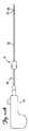
図1A〜1Dの実施形態を参照すると、本発明は、カテーテルシャフトを操作するためのデバイスを対象とする。本発明は、アテローム切除術用カテーテルに関連して記載されるが、任意の他のカテーテルとともに使用され得る。 Referring to the embodiment of FIGS. 1A-1D, the present invention is directed to a device for manipulating a catheter shaft. Although the present invention is described in connection with an atherectomy catheter, it can be used with any other catheter.
アテローム切除術用カテーテル20は、切除要素等の作業要素22を有する。切除要素は、カテーテルのシャフト26のウィンドウ24を通って伸張し得る。理解され得るように、作業要素は、RF要素、可視化要素、またはインプラント送達要素等の任意の他の要素であり得る。通常、カテーテル20は、3Fr〜7Frの作業直径および60cm〜180cmの作業長さを有し得る。 The
シャフトが回転する間、ハンドル28が静止状態を維持できるように、シャフト26を回転させることによって作業要素22の配向が操作され得る。シャフトは、徐々に回転可能であり得るか、または任意の角度の配向に調節可能であり得る。いくつかの実施形態において、シャフトは、穏やかなトルクをシャフトに与えたときに、ハンドルに対するシャフトの回転を許容する様式でハンドルに連結される。他の実施形態において、シャフトは、穏やかなトルクをシャフトに与えたときに、ハンドルに対するシャフトの回転を許容しない様式でハンドルに回転可能に固定される。 While the shaft rotates, the orientation of the
シャフトマニピュレータ10は、回転可能かつ摺動可能にシャフト26に連結され、片手で使用するために構成される。マニピュレータ10は、管腔11、ボタン14、ばね16、およびピボットピン18を有する本体12から構成される。ボタン14は、ピボットピンが摺動可能に嵌まるための孔を有するアーム14から構成される。本体12およびボタン14は、ポリカーボネート、ナイロン、または他の材料で作られてもよく、所望の構成になるように、射出成形され得るか、または他の方法で製造され得る。本体12は、2つの半分体として成形されてもよく、半分体は、ボタン、ピボットピン、およびばねを本体に取り付けた後、超音波、スナップフィット、接着剤、または他の手段によって一緒に結合される。一実施形態において、本体12の2つの半分体は、図1Bの線A−Aによって描写される。ボタン14の面14a、14bは、シャフト26または操作者の指またはその両方に対する摩擦を増加させるために、凹凸があり得る。ばね16およびピボットピン18は、鋼、ばね鋼、もしくは他の金属等の金属、またはポリエステル、液晶ポリマー、ナイロン、もしくは他のポリマー等の工学ポリマーから構成され得る。 The
マニピュレータ10は、通常、ばね16が伸張したロック解除(図1C)位置にあり、ボタン14の面14aをシャフト26から遠ざける。マニピュレータは、ユーザがシャフトに沿って任意の所望の位置にマニピュレータ10を容易に動かすことを許容するように、通常はロックが解除されている。例えば、ユーザは、一方の手でハンドル28を保持しながら、切開付近または導入器シース付近のシャフトの一部分等の、シャフトの露出した遠位部分まで、片手でマニピュレータを移動させることができる。一旦、マニピュレータがシャフトに沿って所望の場所に位置付けられると、シャフト26の回転または並進(またはその両方)は、ユーザが片手でボタン14の面14bを互いに接近するように押し、その後、同じ手でマニピュレータ10を回転または並進させることによって達成され得る(図1D)。 The
次に、図1A〜1Dのカテーテルおよびマニピュレータの使用について説明する。カテーテル20は、任意の既知の様式で患者内に導入される。ユーザがカテーテルを操作することを所望する場合は、ユーザはマニピュレータ10を把持し、カテーテルを操作するために適切な場所まで移動させる。次いで、ユーザは、面14bを押すことによってシャフト上でマニピュレータをロックし、シャフト26と摩擦接触するように、ばね16の力に打ち勝ち、面14aを移動させる。次いで、カッター22の回転、並進、またはその両方を生じさせてアテローム等の組織と接触させるように、マニピュレータを回転させるか、並進させるか、またはその両方が行われる。いくつかの実施形態において、カッター22は、ウィンドウ24の外側に半径方向に伸張され、アテロームを切除するためにカッター22が伸張した状態で、カテーテル20が血管を通して前進させられる。いくつかの実施形態において、アテロームは、カッター22によってカテーテルの内部に方向付けられる。 Next, the use of the catheter and manipulator of FIGS. The
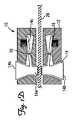
シャフトマニピュレータは、通常はロック解除位置にあると記載してきたが、他の実施形態において、ユーザが顎部に圧力を加えて顎部を閉じるのではなく、顎部を開くように、シャフトマニピュレータが通常ロック位置にあり得る。図2A〜2Dは、通常ロック位置にあるように構成されるシャフトマニピュレータ30を示す。マニピュレータ30は、回転可能かつ摺動可能にシャフト26に連結され、片手で使用するために構成される。マニピュレータ30は、管腔31、アーム34、ばね36、およびピボットピン38を有する本体32から構成される。アーム34は、ピボットピンが摺動可能に嵌まるための孔を有し、面34aを有し、拡張され得る端部34bを有する。本体32、アーム34、面34a、ばね36、およびピボットピン38は、実質的に、本体12、ボタン14、面14
a、ばね16、およびピボットピン38についてそれぞれ上述したような材料からなり、製造され、組み立てられ得る。Although the shaft manipulator has been described as being normally in the unlocked position, in other embodiments, the shaft manipulator is opened so that the user opens the jaw rather than applying pressure to the jaw to close the jaw. It can be in the normal locked position. 2A-2D show a
Each of a,
マニピュレータ30は、通常、ばね36が伸張したロック(図2C)位置にあり、アーム34の面34aをシャフト26と摩擦接触させる。マニピュレータは、ユーザがシャフト26を容易に回転または並進させること(またはその両方)を許容するように、通常はロックされている。面34aをシャフト26と接触させないようにアーム34bを互いに接近するように押し(図2D)、その後、シャフト26上でマニピュレータ30を回転または並進させること(またはその両方)によって、ユーザは、シャフト26に沿って任意の所望の位置まで片手でマニピュレータ30を移動させることができる。例えば、ユーザは、切開付近または導入器シース付近のシャフトの一部分等の、シャフトの露出した遠位部分まで、マニピュレータを移動させることができる。マニピュレータを使用することの利点は、一方の手はハンドル28を保持しながら、シャフトに沿って片手で容易にマニピュレータの位置付けおよび操作ができることである。 The
次に、図2A〜2Dのカテーテルおよびマニピュレータの使用について説明する。カテーテル20は、任意の既知の様式で患者内に導入される。ユーザがカテーテルを操作することを所望する場合は、ユーザはマニピュレータ30を把持し、端部34bを押すことによってマニピュレータをシャフトからロック解除し、シャフト26と摩擦接触しないように面34aを移動させる。次いで、ユーザは、カテーテルを操作するために適切な場所までマニピュレータ30を移動させる。次いで、端部34b上の圧力が除去され、ばね36が、シャフト26と摩擦接触するように面34aを移動させることが可能となる。次いで、カッター22の回転、並進、またはその両方を生じさせてアテローム等の組織と接触させるように、マニピュレータを回転させるか、並進させるか、またはその両方が行われる。いくつかの実施形態において、カッター22は、ウィンドウ24の外側に半径方向に伸張され、アテロームを切除するためにカッター22が伸張した状態で、カテーテル20が血管を通って前進させられる。いくつかの実施形態において、アテロームは、カッター22によってカテーテルの内部に方向付けられる。 Next, the use of the catheter and manipulator of FIGS. The
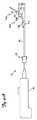
図3Aおよび3Bの実施形態を参照すると、マニピュレータ45とともに使用するための別のカテーテル40が示される。カテーテル40は、上述したカテーテル20と同様であり得るが、上述したシャフト26または別のシャフトと同様のシャフト46を有する作業要素を伴う任意の他のカテーテルであり得、いずれの場合にもループ42が追加される。マニピュレータ45は、上述したマニピュレータ10、30から構成され得るか、または別のマニピュレータであり得る。ハンドル48は、上述したハンドル28と同様であり得るが、任意の他のハンドルであり得る。 Referring to the embodiment of FIGS. 3A and 3B, another
カテーテル40は、マニピュレータとハンドルとの間に位置するループ42を有するシャフト46を含む。ループ42は、シャフトが操作されるとループを形成するように設計される可撓性カテーテル部分でできていてもよいか、または前成形されたループのカテーテル部分であり得、形成されると間隙44から構成される。シャフト46は、ハンドルに対してシャフトが回転または並進しないように、ハンドル48に固定的に連結される。マニピュレータ45を回転または並進させると、ループ42は、ハンドルの配向または位置を変更する必要なく、マニピュレータによってシャフトの遠位部分が回転または並進されるように十分可撓性である。ハンドル48に対してシャフト46を回転または並進させる間、ハンドル48の位置を変化させないよう維持することを可能にしながら、シャフト46の回転または並進に対応するように、ループ42の直径47は大きくなってもまたは小さくなってもよく、間隙44は増加するかまたは減少するかまたはその両方であり得る。
次に、図3Aおよび3Bのカテーテルの使用について説明する。カテーテルは、任意の既知の様式で患者内に導入される。ユーザがカテーテルを操作することを所望する場合は、ユーザはマニピュレータ10を把持し、それを、カテーテルを操作するために適切な場所まで移動させる。次いで、ユーザは、シャフト上でマニピュレータをロックする。シャフトが操作されると、ハンドルの位置を変化させずに、シャフトの回転、並進、またはその両方に対応するために、ループは、必要に応じて間隙を縮小、拡張、または変化させる。いくつかの実施形態において、カッター22は、ウィンドウ24の外側に半径方向に伸張され、アテロームを切除するためにカッター22が伸張した状態で、カテーテル20が血管を通って前進させられる。いくつかの実施形態において、アテロームは、カッター22によってカテーテルの内部に方向付けられる。 Next, the use of the catheter of FIGS. 3A and 3B will be described. The catheter is introduced into the patient in any known manner. If the user desires to manipulate the catheter, the user grasps the
図4Aおよび4Bは、マニピュレータ55とともに使用するための別のカテーテル50を示す。シャフトの遠位部分は、切除要素を血管壁に対して付勢するための並置力(apposition force)を提供するように成形される。カテーテル50は、上述したカテーテル20と同様であり得るが、上述したシャフト56または別のシャフトと同様のシャフト56を有する作業要素を伴う任意の他のカテーテルであり得、いずれの場合にも、ジョグ51jおよび前形成された屈曲部51p、51dが追加される。カテーテル50はまた、それぞれ、作業要素22およびウィンドウ24と構造、材料、および機能において同様であり得る作業要素52およびウィンドウ54から構成される。カテーテルが血管内に位置付けられると作業要素52が血管壁に対して付勢されるように、ウィンドウ54は、シャフト上の半径方向内側の位置に位置する。ジョグ51jおよび前形成された屈曲部51p、51dは、連携して作業要素52を付勢し、血管内の切除される物質と接触させる。マニピュレータ55は、上述したマニピュレータ10、30から構成され得るか、または別のマニピュレータであり得る。マニピュレータ55をカテーテル50とともに使用することは任意的である。ハンドル58は、上述したハンドル28と同様であり得るが、任意の他のハンドルであり得る。 4A and 4B show another
カテーテルシャフト56は、ジョグ51jおよび前形成された屈曲部51p、51dを含む。ジョグ51jは、シャフト56の遠位部分56dがシャフト56の中央部分56mに対して急に屈曲することを許容するヒンジ構造から構成される。ジョグを行うことが可能なカテーテル構造は、2004年7月21日に出願され、米国特許第2005/0177068A1として公開された米国特許出願第10/896,741号の段落[0092]〜[0094]、[0100]〜[0102]、[0105]〜[0107]、ならびに図1、1A、2、4A、および4Bにさらに記載される。米国特許公開公報US2005/0177068号の内容すべては、参照により本明細書に組み込まれる。一実施形態において、前形成された屈曲部は、中央部分および中央部分の近位のカテーテルシャフトの部分が第1の平面内に位置するように形成され、ヒンジ要素は、第1の平面内でのみ、中央部分に対する遠位部分の屈曲を許容するように構成される。前形成された屈曲部51p、51dは、カテーテル56に金型の形状を取らせるように、遠位部分56dを金型内に拘束し、その後、過熱することによって形成され得るか、または、当業者に既知である他の手段によって形成され得る。前形成された屈曲部51pは、前形成された屈曲部51dの角度53dよりも小さい角度53pを有する。90〜150度の前形成された屈曲部51pの角度が企図される。一実施形態において、前形成された屈曲部51pの角度は、100〜120度である。他の実施形態において、角度53pは、95、105、110、115、125、130、または140度である。100〜180度の前形成された屈曲部51dの角度53dが企図される。一実施形態において、前形成された屈曲部51dの角度は、120〜140度である。他の実施形態において、角53dは、110、130、150、160、または170度である。前形成された屈曲部51pから前形成された屈曲部51dまでの長さは、概して、前形成された屈曲部51dからジョグ51jまでの長さよりも長い。0.5〜2.0インチの前形成された屈曲部51pから前形成された屈曲部51dまでの長さが企図される。一実施形態において、前形成された屈曲部51pから前形成された屈曲部51dまでの長さは、1.00〜1.25インチである。他の実施形態において、前形成された屈曲部51pから前形成された屈曲部51dまでの長さは、0.75、1.5、または1.75インチである。0.125〜1.0インチの前形成された屈曲部51dからジョグ51jまでの長さが企図される。一実施形態において、前形成された屈曲部51dからジョグ51eまでの長さは、0.375〜0.625インチである。
いくつかの実施形態において、前形成された屈曲部51dからジョグ51jまでの長さは、0.25、0.5、0.75、または0.875インチである。組み合わせた屈曲部51d、51pならびに屈曲部間および屈曲部とジョグとの間の距離により、カテーテル56は、カテーテル56の非屈曲部分からジョグ56jまでの最大偏位56eを有する。一般に、本発明のカテーテルは、そのカテーテル50が使用される血管または導管の直径よりも大きい偏位を有するように選択される。3〜40ミリメートルの偏位56eが企図される。一実施形態において、偏位56eは、5〜8mmである。いくつかの実施形態において、偏位56eは、4、5、6、7、8、10、12、15、20、25、30、または35ミリメートルである。The
In some embodiments, the length from the
カテーテル50が、拘束されない偏位56eよりも小さい直径Dの血管V内に位置付けられると、前形成された屈曲部51pおよび51dは、それらの偏向されていない前形成された角度よりも大きな角度になることを余儀なくされ、その一方で、ジョグ51jは、カテーテル50の最遠位部分が血管Vの内壁に沿って配向されることを可能にする。前形成された屈曲部がそれらの偏向されていない前形成された角度に戻ろうとすると、ジョグ56jと屈曲部51p、51dとの間のこの連携により、ウィンドウ54を押すかまたは付勢して血管Vの内壁と接触させる。前形成された屈曲部51dは、血管径の小さい端部で血管Vの内壁に対するカッター52およびウィンドウ54の並置力を維持する。血管径が増加するにつれて、前形成された屈曲部51pは、最終的にはカテーテルの先端にも並置力を印加し始める。0.05〜0.5lbの付勢力が企図される。一実施形態において、付勢力は、0.1lbである。いくつかの実施形態において、付勢力は、0.075、0.2、0.3、または0.4lbである。カッター等の作業要素52は、アテローム等の切除される物質と接触するように、ウィンドウ54を通して伸張され得る。切除中は、カッターを血管の内部表面から離れるように偏向させる傾向にある切除力が、上述したように生成される付勢力によって抵抗を受ける。シャフト56の遠位部分は、ウィンドウ54が確実に円周方向に配向され、切除される物質と接触するように、マニピュレータ55(使用される場合は)によって回転させられるか、並進させられるか、またはその両方が行われ得る。 When the
次に、図4Aおよび4Bのカテーテルの使用について説明する。血管Vの内径よりも大きい偏位56eを有するカテーテル50が選択される。任意で、カテーテルは、物質が除去される血管Vの場所まで、任意の既知の様式で、ガイドワイヤ上で患者内に導入される。ガイドワイヤ上で導入される場合、カテーテルは、ある程度真っ直ぐになる傾向があり、その場所までガイドワイヤに従う。前形成された屈曲部51p、51dは、ジョグ51jと連携して、血管Vの内壁に対してウィンドウ54を付勢する。いくつかの実施形態において、カッター52は、ウィンドウ54の外側に半径方向に伸張され、アテロームを切除するためにカッター52が伸張した状態で、カテーテル50が血管を通って前進させられる。いくつかの実施形態において、アテロームは、カッター52によってカテーテルの内部に方向付けられる。任意で、ユーザがカテーテルを操作することを所望する場合は、ユーザはマニピュレータ55を把持し、カテーテルを操作するために適切な場所まで移動させる。次いで、ユーザは、シャフト56上でマニピュレータをロックし、ハンドル58の位置は変化させずに、シャフトを回転させるか、並進させるか、またはその両方を行う。 Next, the use of the catheter of FIGS. 4A and 4B will be described. A
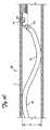
図5A〜5Cは、マニピュレータ65とともに使用するための別のカテーテル60を示す。シャフトの遠位部分は、血管壁に対して切除要素を付勢するための並置力を提供するように成形される。カテーテル60は、上述したカテーテル20と同様であり得るが、上述したシャフト26または別のシャフトと同様のシャフト66を有する作業要素を伴う任意の他のカテーテルであり得、いずれの場合にも、ジョグ61jおよび連続的に半径が減少する曲線61が追加される。ジョグ61jは、構造、材料、および機能において、ジョグ51jと同様であり得る。カテーテル60はまた、それぞれ、作業要素22およびウィンドウ24と構造、材料、および機能において同様であり得る作業要素62およびウィンドウ64から構成される。カテーテルが血管内に位置付けられたときに作業要素62が血管壁に対して付勢されるように、作業要素62は、シャフト上の半径方向内側の位置に位置する。ジョグ61jおよび連続的に半径が減少する曲線61は、連携して作業要素62を付勢し、血管内の切除される物質と接触させる。マニピュレータ65は、上述したマニピュレータ10、30から構成され得るか、または別のマニピュレータであり得る。マニピュレータ65をカテーテル60と使用することは任意的である。ハンドル68は、上述した28と同様であり得るが、任意の他のハンドルであり得る。 5A-5C show another
カテーテルシャフト66は、ジョグ61jおよび連続的に半径が減少する曲線61を含む。連続的に半径が減少する曲線61は、遠位部分66dに金型の形状を取らせるように、カテーテルシャフト66の遠位部分66dを金型内に拘束し、その後、過熱することによって形成され得るか、または、当業者に既知である他の手段によって形成され得る。遠位部分66dは、少なくとも90度から少なくとも720度まで丸められ得る。図5Aは、約360度丸められたシャフトを示し、図5Bは、約720度丸められたシャフトを示す。他の実施形態において、遠位部分66dは、120、150、180、240、300、480、または600度丸められる。最大曲げ径63は、3mmから50mmまで異なってもよいが、特定の用途によって、最大曲げ径はこの範囲外であり得る。一実施形態において、最大曲げ径は10〜12mmである。他の実施形態において、最大曲げ径は4、6、8、15、20、25、30、または40mmである。 The
別の実施形態において、連続的に半径が減少する曲線61は、多数の個々の前形成された屈曲部(図示せず)から構成され得る。理解され得るように、半径が減少するセクションの数は異なってもよい。例えば、2〜100個のセクションを有するカテーテルが企図される。他の実施形態において、カテーテルは、4、6、8、10、15、20、40、60、75、または100個のセクションを有し得る。さらに別の実施形態において、図5A〜5Cの連続的に変化する実施形態によって開示されるように、カテーテルは無限の数のセクションを有する。連続的に減少する半径は、血管径の範囲にわたって比較的均一な並置力を提供することが意図される。血管のジオメトリおよびサイズは患者ごとにかなり異なるため、当然、使用中の実際の並置力はかなり異なってもよいが、シャフトの形状は、様々な血管のサイズにわたって均一な力を提供する傾向にある。 In another embodiment, the continuously decreasing
カテーテル60が、最大曲げ径63よりも小さい直径Dの血管V内に位置付けられると、連続的に半径が減少する曲線61は直径を増加することを余儀なくされ、その一方で、ジョグ61jは、カテーテル60の最遠位部分が血管Vの内壁に沿って配向されることを可能にする。湾曲部61がその偏向されていない直径に戻ろうとすると、ジョグ56jと湾曲部61との間の連携により、ウィンドウ64を押すかまたは付勢して血管Vの内壁と接触させる。カッター等の作業要素62は、アテローム等の切除される物質と接触するように、ウィンドウ64を通して伸張され得る。切除中は、カッターを血管の内部表面から離れるように偏向させる傾向にある切除力が、上述したように生成される付勢力によって抵抗を受ける。シャフト66の遠位部分は、ウィンドウ64が確実に円周方向に配向され、切除される物質と接触するように、マニピュレータ65(使用される場合は)によって回転させられるか、並進させられるか、またはその両方が行われ得る。 When the
次に、図5A〜5Cのカテーテルの使用について説明する。カテーテルは、物質が除去される場所まで、任意の既知の様式で、ガイドワイヤ上で患者内に導入される。ガイドワイヤ上で導入される場合、カテーテルは、ある程度真っ直ぐになる傾向があり、その場所までガイドワイヤに従う。湾曲部61は、ジョグ61jと連携して、血管Vの内壁に対してウィンドウ64を付勢する。いくつかの実施形態において、カッター62は、ウィンドウ64の外側に半径方向に伸張され、アテロームを切除するためにカッター62が伸張した状態で、カテーテル60が血管を通って前進させられる。いくつかの実施形態において、アテロームは、カッター62によってカテーテルの内部に方向付けられる。任意で、ユーザがカテーテルを操作することを所望する場合は、ユーザはマニピュレータ65を把持し、カテーテルを操作するために適切な場所まで移動させる。次いで、ユーザは、シャフト66上でマニピュレータをロックし、ハンドル68の位置は変化させずに、シャフトを回転させるか、並進させるか、またはその両方を行う。 Next, the use of the catheter of FIGS. The catheter is introduced into the patient over the guidewire in any known manner until the material is removed. When introduced over a guidewire, the catheter tends to be somewhat straight and follows the guidewire to that location. The bending
本発明は、好ましい実施形態に関連して記載してきたが、当然、上述した例示的な実施形態から離れて実践され得る。 Although the present invention has been described in connection with a preferred embodiment, it should be understood that it can be practiced apart from the exemplary embodiments described above.
Claims (12)
Translated fromJapanese遠位端および近位端ならびに管腔を画定する側壁を有する、細長い管状シャフトを備え、
該細長い管状シャフトは、第1の屈曲部と、該第1の屈曲部の遠位に所定の距離で位置する第2の屈曲部と、該側壁を通り延在するウィンドウとを有し、該ウィンドウは、細長い管状部材の該第2の屈曲部の遠位かつ該遠位端の近位に位置し、該第1の屈曲部は、第1の前形成された角度を画定し、該第2の屈曲部は、該第1の前形成された角度より大きい第2の前形成された角度を画定し、該細長い管状シャフトは、該血管内における使用中に、該第1の屈曲部が該第1の前形成された角度より大きい第1の屈曲角度を画定するように屈曲され、かつ該第2の屈曲部が該第2の前形成された角度より大きい第2の屈曲角度を画定するように屈曲されるようにサイズ決定され、該第1および第2の前形成された角度ならびに該所定の距離は、使用中に、該血管の壁の該部位に対して該ウィンドウを付勢するように選択される、
カテーテル。A catheter for accessing a part of a blood vessel wall,
An elongated tubular shaft having distal and proximal ends and side walls defining a lumen;
The elongated tubular shaft has a first bend, a second bend located at a predetermined distance distal to the first bend, and a window extending through the sidewall, The window is located distal to and proximal to the second bend of the elongate tubular member,the first bend defininga first pre-formed angle andthe first bend second bent portion defines apreformed angle larger than the secondpreformed angle of the first,the elongated tubular shaft, in use in the blood vessel, the bending portion is first The second bend is bent to define a first bending angle that is greater than the first pre-formed angle, and the second bend defines a second bending angle that is greater than the second pre-formed angle. is sized to be bent so as to, first and secondpreformed angle and the predetermined distance, During use, it is selected to urge the window against the site of the wall of the blood vessel,
catheter.
The catheter of claim 3, wherein the working element is an atherectomy resection device.
Applications Claiming Priority (5)
| Application Number | Priority Date | Filing Date | Title |
|---|---|---|---|
| US10483608P | 2008-10-13 | 2008-10-13 | |
| US61/104,836 | 2008-10-13 | ||
| US12260108P | 2008-12-15 | 2008-12-15 | |
| US61/122,601 | 2008-12-15 | ||
| PCT/US2009/060496WO2010045226A2 (en) | 2008-10-13 | 2009-10-13 | Devices and methods for manipulating a catheter shaft |
Related Child Applications (1)
| Application Number | Title | Priority Date | Filing Date |
|---|---|---|---|
| JP2013272114ADivisionJP5793178B2 (en) | 2008-10-13 | 2013-12-27 | Device and method for operating a catheter shaft |
Publications (3)
| Publication Number | Publication Date |
|---|---|
| JP2012505060A JP2012505060A (en) | 2012-03-01 |
| JP2012505060A5 JP2012505060A5 (en) | 2012-10-25 |
| JP5555242B2true JP5555242B2 (en) | 2014-07-23 |
Family
ID=41664939
Family Applications (2)
| Application Number | Title | Priority Date | Filing Date |
|---|---|---|---|
| JP2011531255AActiveJP5555242B2 (en) | 2008-10-13 | 2009-10-13 | Device and method for operating a catheter shaft |
| JP2013272114AActiveJP5793178B2 (en) | 2008-10-13 | 2013-12-27 | Device and method for operating a catheter shaft |
Family Applications After (1)
| Application Number | Title | Priority Date | Filing Date |
|---|---|---|---|
| JP2013272114AActiveJP5793178B2 (en) | 2008-10-13 | 2013-12-27 | Device and method for operating a catheter shaft |
Country Status (10)
| Country | Link |
|---|---|
| US (3) | US8414604B2 (en) |
| EP (2) | EP2358282B1 (en) |
| JP (2) | JP5555242B2 (en) |
| KR (1) | KR101645754B1 (en) |
| CN (1) | CN102223847B (en) |
| AU (1) | AU2009303501B2 (en) |
| BR (1) | BRPI0920206A2 (en) |
| CA (1) | CA2739665C (en) |
| RU (1) | RU2503422C2 (en) |
| WO (1) | WO2010045226A2 (en) |
Families Citing this family (79)
| Publication number | Priority date | Publication date | Assignee | Title |
|---|---|---|---|---|
| US7713279B2 (en) | 2000-12-20 | 2010-05-11 | Fox Hollow Technologies, Inc. | Method and devices for cutting tissue |
| US7708749B2 (en) | 2000-12-20 | 2010-05-04 | Fox Hollow Technologies, Inc. | Debulking catheters and methods |
| US8328829B2 (en) | 1999-08-19 | 2012-12-11 | Covidien Lp | High capacity debulking catheter with razor edge cutting window |
| US6299622B1 (en) | 1999-08-19 | 2001-10-09 | Fox Hollow Technologies, Inc. | Atherectomy catheter with aligned imager |
| JP4080874B2 (en) | 2000-12-20 | 2008-04-23 | フォックス ハロウ テクノロジーズ,インコーポレイティド | Bulking catheter |
| US8246640B2 (en) | 2003-04-22 | 2012-08-21 | Tyco Healthcare Group Lp | Methods and devices for cutting tissue at a vascular location |
| US20070276419A1 (en) | 2006-05-26 | 2007-11-29 | Fox Hollow Technologies, Inc. | Methods and devices for rotating an active element and an energy emitter on a catheter |
| US8784440B2 (en) | 2008-02-25 | 2014-07-22 | Covidien Lp | Methods and devices for cutting tissue |
| US9125562B2 (en) | 2009-07-01 | 2015-09-08 | Avinger, Inc. | Catheter-based off-axis optical coherence tomography imaging system |
| US8696695B2 (en) | 2009-04-28 | 2014-04-15 | Avinger, Inc. | Guidewire positioning catheter |
| US9788790B2 (en) | 2009-05-28 | 2017-10-17 | Avinger, Inc. | Optical coherence tomography for biological imaging |
| US8414604B2 (en) | 2008-10-13 | 2013-04-09 | Covidien Lp | Devices and methods for manipulating a catheter shaft |
| CN102625673B (en) | 2009-04-29 | 2014-12-24 | 泰科保健集团有限合伙公司 | Methods and devices for cutting and abrading tissue |
| WO2010132748A1 (en) | 2009-05-14 | 2010-11-18 | Fox Hollow Technologies, Inc. | Easily cleaned atherectomy catheters and methods of use |
| WO2011003006A2 (en) | 2009-07-01 | 2011-01-06 | Avinger, Inc. | Atherectomy catheter with laterally-displaceable tip |
| WO2011068932A1 (en) | 2009-12-02 | 2011-06-09 | Fox Hollow Technologies, Inc. | Methods and devices for cutting tissue |
| WO2011072068A2 (en) | 2009-12-08 | 2011-06-16 | Avinger, Inc. | Devices and methods for predicting and preventing restenosis |
| CN102695463B (en) | 2009-12-11 | 2015-01-14 | 泰科保健集团有限合伙公司 | Material removal device having improved material capture efficiency and methods of use |
| RU2538174C2 (en) | 2010-06-14 | 2015-01-10 | Ковидиен Лп | Device for material removal |
| US10548478B2 (en) | 2010-07-01 | 2020-02-04 | Avinger, Inc. | Balloon atherectomy catheters with imaging |
| US9345510B2 (en) | 2010-07-01 | 2016-05-24 | Avinger, Inc. | Atherectomy catheters with longitudinally displaceable drive shafts |
| WO2014039096A1 (en) | 2012-09-06 | 2014-03-13 | Avinger, Inc. | Re-entry stylet for catheter |
| US11382653B2 (en) | 2010-07-01 | 2022-07-12 | Avinger, Inc. | Atherectomy catheter |
| US10085742B2 (en)* | 2010-07-29 | 2018-10-02 | Boston Scientific Scimed, Inc. | Adjustable device for delivering implants and methods of delivering implants |
| CA2815186C (en) | 2010-10-28 | 2015-12-29 | Covidien Lp | Material removal device and method of use |
| KR20150020240A (en) | 2010-11-11 | 2015-02-25 | 코비디엔 엘피 | Flexible debulking catheters with imaging and methods of use and manufacture |
| CN103153381B (en)* | 2011-02-25 | 2014-12-03 | 泰尔茂株式会社 | Fixtures and Conduit Kits |
| US9949754B2 (en) | 2011-03-28 | 2018-04-24 | Avinger, Inc. | Occlusion-crossing devices |
| EP2691038B1 (en) | 2011-03-28 | 2016-07-20 | Avinger, Inc. | Occlusion-crossing devices, imaging, and atherectomy devices |
| US8840630B2 (en) | 2011-06-15 | 2014-09-23 | Cook Medical Technologies Llc | Button release handle |
| EP2750862B1 (en) | 2011-09-01 | 2016-07-06 | Covidien LP | Catheter with helical drive shaft and methods of manufacture |
| EP3653151A1 (en) | 2011-10-17 | 2020-05-20 | Avinger, Inc. | Atherectomy catheters and non-contact actuation mechanism for catheters |
| US9345406B2 (en) | 2011-11-11 | 2016-05-24 | Avinger, Inc. | Occlusion-crossing devices, atherectomy devices, and imaging |
| US9351757B2 (en) | 2012-01-17 | 2016-05-31 | Covidien Lp | Material removal device and method of use |
| US9557156B2 (en) | 2012-05-14 | 2017-01-31 | Avinger, Inc. | Optical coherence tomography with graded index fiber for biological imaging |
| EP2849660B1 (en) | 2012-05-14 | 2021-08-25 | Avinger, Inc. | Atherectomy catheter drive assemblies |
| WO2013172970A1 (en) | 2012-05-14 | 2013-11-21 | Avinger, Inc. | Atherectomy catheters with imaging |
| US9498247B2 (en) | 2014-02-06 | 2016-11-22 | Avinger, Inc. | Atherectomy catheters and occlusion crossing devices |
| US11284916B2 (en) | 2012-09-06 | 2022-03-29 | Avinger, Inc. | Atherectomy catheters and occlusion crossing devices |
| US9532844B2 (en) | 2012-09-13 | 2017-01-03 | Covidien Lp | Cleaning device for medical instrument and method of use |
| US9943329B2 (en) | 2012-11-08 | 2018-04-17 | Covidien Lp | Tissue-removing catheter with rotatable cutter |
| EP2931151B1 (en) | 2012-12-12 | 2019-11-27 | Covidien LP | Tissue-removing catheter including urging mechanism |
| WO2014143064A1 (en) | 2013-03-15 | 2014-09-18 | Avinger, Inc. | Chronic total occlusion crossing devices with imaging |
| CN105228514B (en) | 2013-03-15 | 2019-01-22 | 阿维格公司 | Optical Pressure Sensor Assembly |
| US11096717B2 (en) | 2013-03-15 | 2021-08-24 | Avinger, Inc. | Tissue collection device for catheter |
| EP3019096B1 (en) | 2013-07-08 | 2023-07-05 | Avinger, Inc. | System for identification of elastic lamina to guide interventional therapy |
| US9456843B2 (en)* | 2014-02-03 | 2016-10-04 | Covidien Lp | Tissue-removing catheter including angular displacement sensor |
| US9526519B2 (en)* | 2014-02-03 | 2016-12-27 | Covidien Lp | Tissue-removing catheter with improved angular tissue-removing positioning within body lumen |
| MX2016010141A (en) | 2014-02-06 | 2017-04-06 | Avinger Inc | Atherectomy catheters and occlusion crossing devices. |
| JP5954747B2 (en)* | 2014-03-20 | 2016-07-20 | 朝日インテック株式会社 | catheter |
| WO2015200702A1 (en) | 2014-06-27 | 2015-12-30 | Covidien Lp | Cleaning device for catheter and catheter including the same |
| US10357277B2 (en) | 2014-07-08 | 2019-07-23 | Avinger, Inc. | High speed chronic total occlusion crossing devices |
| US10314667B2 (en) | 2015-03-25 | 2019-06-11 | Covidien Lp | Cleaning device for cleaning medical instrument |
| US10568520B2 (en) | 2015-07-13 | 2020-02-25 | Avinger, Inc. | Micro-molded anamorphic reflector lens for image guided therapeutic/diagnostic catheters |
| US10292721B2 (en) | 2015-07-20 | 2019-05-21 | Covidien Lp | Tissue-removing catheter including movable distal tip |
| US10179046B2 (en)* | 2015-08-14 | 2019-01-15 | Edwards Lifesciences Corporation | Gripping and pushing device for medical instrument |
| US10314664B2 (en) | 2015-10-07 | 2019-06-11 | Covidien Lp | Tissue-removing catheter and tissue-removing element with depth stop |
| CN108368715B (en)* | 2015-10-19 | 2020-03-13 | 伊利诺斯工具制品有限公司 | Door handle incorporating dual hinged sound attenuating flap feature |
| JP6927986B2 (en) | 2016-01-25 | 2021-09-01 | アビンガー・インコーポレイテッドAvinger, Inc. | OCT imaging catheter with delay compensation |
| EP3435892B1 (en) | 2016-04-01 | 2024-04-03 | Avinger, Inc. | Atherectomy catheter with serrated cutter |
| US10456161B2 (en)* | 2016-04-14 | 2019-10-29 | Covidien Lp | Tissue-removing catheter with adjustment mechanism |
| US9962180B2 (en) | 2016-04-27 | 2018-05-08 | Covidien Lp | Catheter including drive assembly for rotating and reciprocating tissue-removing element |
| US11344327B2 (en) | 2016-06-03 | 2022-05-31 | Avinger, Inc. | Catheter device with detachable distal end |
| WO2018006041A1 (en)* | 2016-06-30 | 2018-01-04 | Avinger, Inc. | Atherectomy catheter with shapeable distal tip |
| MA46282A (en)* | 2016-09-21 | 2019-07-31 | 3Nt Medical Ltd | DILATOR RESEARCHER |
| US20180311468A1 (en)* | 2017-04-27 | 2018-11-01 | The Regents Of The University Of California | Force sensor and monitoring device |
| US10137447B1 (en) | 2017-05-17 | 2018-11-27 | Biotix, Inc. | Ergonomic fluid handling tubes |
| US10874839B2 (en)* | 2017-07-13 | 2020-12-29 | Acclarent, Inc. | Adjustable instrument for dilation of anatomical passageway |
| US12167867B2 (en) | 2018-04-19 | 2024-12-17 | Avinger, Inc. | Occlusion-crossing devices |
| CN114746033B (en) | 2019-10-18 | 2025-01-10 | 阿维格公司 | Blocking crossing device |
| US20220392065A1 (en) | 2020-01-07 | 2022-12-08 | Cleerly, Inc. | Systems, methods, and devices for medical image analysis, diagnosis, risk stratification, decision making and/or disease tracking |
| US11969280B2 (en) | 2020-01-07 | 2024-04-30 | Cleerly, Inc. | Systems, methods, and devices for medical image analysis, diagnosis, risk stratification, decision making and/or disease tracking |
| US11501436B2 (en) | 2020-01-07 | 2022-11-15 | Cleerly, Inc. | Systems, methods, and devices for medical image analysis, diagnosis, risk stratification, decision making and/or disease tracking |
| US12318161B2 (en) | 2021-10-05 | 2025-06-03 | Siemens Healthineers Endovascular Robotics, Inc. | Robotic actuation of elongated medical devices |
| US20250032149A1 (en)* | 2021-12-06 | 2025-01-30 | Avinger, Inc. | Atherectomy catheter with shapeable distal tip |
| CN114470487B (en)* | 2021-12-22 | 2023-02-14 | 广东博迈医疗科技股份有限公司 | Medical guide wire and interventional medical equipment |
| US12406365B2 (en) | 2022-03-10 | 2025-09-02 | Cleerly, Inc. | Systems, devices, and methods for non-invasive image-based plaque analysis and risk determination |
| US20250143657A1 (en) | 2022-03-10 | 2025-05-08 | Cleerly, Inc. | Systems, devices, and methods for non-invasive image-based plaque analysis and risk determination |
| US20250217981A1 (en) | 2022-03-10 | 2025-07-03 | Cleerly, Inc. | Systems, methods, and devices for image-based plaque analysis and risk determination |
Family Cites Families (603)
| Publication number | Priority date | Publication date | Assignee | Title |
|---|---|---|---|---|
| US1481078A (en)* | 1922-11-24 | 1924-01-15 | Albertson & Company | Flexible shafting |
| US2178790A (en)* | 1938-05-07 | 1939-11-07 | Abner E Henry | Cutting implement |
| US2234686A (en)* | 1940-01-02 | 1941-03-11 | Ind Patents Corp | Needle and clamp therefor |
| US2701559A (en)* | 1951-08-02 | 1955-02-08 | William A Cooper | Apparatus for exfoliating and collecting diagnostic material from inner walls of hollow viscera |
| US2850007A (en)* | 1956-05-31 | 1958-09-02 | American Cyanamid Co | Biopsy device |
| US3064651A (en)* | 1959-05-26 | 1962-11-20 | Henderson Edward | Hypodermic needle |
| US3082805A (en)* | 1960-12-21 | 1963-03-26 | John H Royce | Tissue macerator |
| US3320957A (en)* | 1964-05-21 | 1967-05-23 | Sokolik Edward | Surgical instrument |
| GB1235321A (en)* | 1968-01-30 | 1971-06-09 | Nat Res Dev | Improvements in or relating to drills for clearing obstructions |
| US3732858A (en)* | 1968-09-16 | 1973-05-15 | Surgical Design Corp | Apparatus for removing blood clots, cataracts and other objects from the eye |
| ES152231Y (en)* | 1969-10-02 | 1970-07-01 | Ballestero Sierra | A PERFECTED TROCAR. |
| US3683891A (en)* | 1970-06-26 | 1972-08-15 | Marshall Eskridge | Tissue auger |
| US3749085A (en)* | 1970-06-26 | 1973-07-31 | J Willson | Vascular tissue removing device |
| US3945375A (en)* | 1972-04-04 | 1976-03-23 | Surgical Design Corporation | Rotatable surgical instrument |
| SU442795A1 (en) | 1972-04-27 | 1974-09-15 | Л.С. Юхин | Intravascular Surgery Device |
| US3815604A (en)* | 1972-06-19 | 1974-06-11 | Malley C O | Apparatus for intraocular surgery |
| US3800783A (en)* | 1972-06-22 | 1974-04-02 | K Jamshidi | Muscle biopsy device |
| US3831585A (en)* | 1972-07-19 | 1974-08-27 | T Brondy | Retrograde renal biopsy device |
| JPS5042162A (en) | 1973-08-21 | 1975-04-17 | ||
| US3837345A (en)* | 1973-08-31 | 1974-09-24 | A Matar | Venous valve snipper |
| JPS5529376B2 (en) | 1973-09-17 | 1980-08-02 | ||
| US3845375A (en)* | 1973-11-09 | 1974-10-29 | Mclaughlin Ward & Co | Electronic rotational sensor |
| US3937222A (en)* | 1973-11-09 | 1976-02-10 | Surgical Design Corporation | Surgical instrument employing cutter means |
| JPS5184679A (en) | 1975-01-24 | 1976-07-24 | Niino Giken Kk | BIATSUKANCHOWAKUTAITSUKIDAIYAFURAMUNO SEIZOHOHO |
| US3976077A (en)* | 1975-02-03 | 1976-08-24 | Kerfoot Jr Franklin W | Eye surgery device |
| US4007732A (en)* | 1975-09-02 | 1977-02-15 | Robert Carl Kvavle | Method for location and removal of soft tissue in human biopsy operations |
| US4038985A (en)* | 1975-10-07 | 1977-08-02 | Medico Developments, Inc. | Device for repairing arteries |
| US3995619A (en)* | 1975-10-14 | 1976-12-07 | Glatzer Stephen G | Combination subcutaneous suture remover, biopsy sampler and syringe |
| US4030503A (en)* | 1975-11-05 | 1977-06-21 | Clark Iii William T | Embolectomy catheter |
| US4020847A (en)* | 1975-11-05 | 1977-05-03 | Clark Iii William T | Rotating cutter catheter |
| US4034744A (en)* | 1975-11-13 | 1977-07-12 | Smith Kline Instruments, Inc. | Ultrasonic scanning system with video recorder |
| US4177797A (en)* | 1977-03-04 | 1979-12-11 | Shelby M. Baylis | Rotary biopsy device and method of using same |
| US4112708A (en)* | 1976-06-21 | 1978-09-12 | Nippon Cable Systems Inc. | Flexible drive cable |
| SU665908A1 (en) | 1977-11-09 | 1979-06-05 | Silin Semen A | Device for intravascular surgery |
| US4210146A (en)* | 1978-06-01 | 1980-07-01 | Anton Banko | Surgical instrument with flexible blade |
| US4306562A (en)* | 1978-12-01 | 1981-12-22 | Cook, Inc. | Tear apart cannula |
| JPS5581633A (en)* | 1978-12-15 | 1980-06-19 | Olympus Optical Co | Endoscope |
| US4362156A (en)* | 1979-04-18 | 1982-12-07 | Riverain Corporation | Intravenous infusion assembly |
| DE2949865C2 (en)* | 1979-12-12 | 1985-04-18 | B. Braun Melsungen Ag, 3508 Melsungen | Hose connection for medical devices |
| US4273128A (en)* | 1980-01-14 | 1981-06-16 | Lary Banning G | Coronary cutting and dilating instrument |
| US4306570A (en)* | 1980-08-20 | 1981-12-22 | Matthews Larry S | Counter rotating biopsy needle |
| US4368730A (en)* | 1981-02-12 | 1983-01-18 | Nigel Sharrock | Intravenous catheter |
| GB2093353B (en) | 1981-02-25 | 1984-09-19 | Dyonics Inc | A surgical instrument for arthroscopic arthroplasty |
| US4436091A (en)* | 1981-03-20 | 1984-03-13 | Surgical Design Corporation | Surgical cutting instrument with release mechanism |
| JPS5887494U (en)* | 1981-12-05 | 1983-06-14 | 株式会社モリタ製作所 | Speed control device for small medical motors |
| CH660015A5 (en) | 1982-02-01 | 1987-03-13 | Sandoz Ag | PREPARATIONS CONTAINING POLYMER AND SURFACTANTS, THEIR PRODUCTION AND USE. |
| US4445509A (en)* | 1982-02-04 | 1984-05-01 | Auth David C | Method and apparatus for removal of enclosed abnormal deposits |
| US4692141A (en)* | 1982-03-08 | 1987-09-08 | Mahurkar Sakharam D | Double lumen catheter |
| US4512344A (en)* | 1982-05-12 | 1985-04-23 | Barber Forest C | Arthroscopic surgery dissecting apparatus |
| US4424045A (en)* | 1982-05-24 | 1984-01-03 | Pennwalt Corporation | Rigid high speed flexible shaft casing assembly for tight radii installations |
| DE3235612A1 (en) | 1982-09-25 | 1984-03-29 | Bayer Ag, 5090 Leverkusen | MICROEMULSIONS |
| US4490139A (en)* | 1983-01-28 | 1984-12-25 | Eli Lilly And Company | Implant needle and method |
| US4936987A (en)* | 1983-03-07 | 1990-06-26 | Calgon Corporation | Synergistic scale and corrosion inhibiting admixtures containing carboxylic acid/sulfonic acid polymers |
| US4603694A (en)* | 1983-03-08 | 1986-08-05 | Richards Medical Company | Arthroscopic shaver |
| US4730616A (en)* | 1983-08-12 | 1988-03-15 | Advanced Cardiovascular Systems, Inc. | Multiple probe angioplasty apparatus and method |
| US5669936A (en) | 1983-12-09 | 1997-09-23 | Endovascular Technologies, Inc. | Endovascular grafting system and method for use therewith |
| US5104399A (en) | 1986-12-10 | 1992-04-14 | Endovascular Technologies, Inc. | Artificial graft and implantation method |
| DE3347671A1 (en)* | 1983-12-31 | 1985-07-11 | Richard Wolf Gmbh, 7134 Knittlingen | TISSUE SAMPLING INSTRUMENT |
| US4589412A (en)* | 1984-01-03 | 1986-05-20 | Intravascular Surgical Instruments, Inc. | Method and apparatus for surgically removing remote deposits |
| US4631052A (en)* | 1984-01-03 | 1986-12-23 | Intravascular Surgical Instruments, Inc. | Method and apparatus for surgically removing remote deposits |
| US4957482A (en) | 1988-12-19 | 1990-09-18 | Surgical Systems & Instruments, Inc. | Atherectomy device with a positive pump means |
| US4979939A (en) | 1984-05-14 | 1990-12-25 | Surgical Systems & Instruments, Inc. | Atherectomy system with a guide wire |
| US4894051A (en)* | 1984-05-14 | 1990-01-16 | Surgical Systems & Instruments, Inc. | Atherectomy system with a biasing sleeve and method of using the same |
| US5007896A (en) | 1988-12-19 | 1991-04-16 | Surgical Systems & Instruments, Inc. | Rotary-catheter for atherectomy |
| US5024651A (en) | 1984-05-14 | 1991-06-18 | Surgical Systems & Instruments, Inc. | Atherectomy system with a sleeve |
| US4883458A (en)* | 1987-02-24 | 1989-11-28 | Surgical Systems & Instruments, Inc. | Atherectomy system and method of using the same |
| US4842579B1 (en)* | 1984-05-14 | 1995-10-31 | Surgical Systems & Instr Inc | Atherectomy device |
| US4754755A (en)* | 1984-05-14 | 1988-07-05 | Husted Royce Hill | Catheter with a rotary blade |
| US4886490A (en)* | 1984-05-14 | 1989-12-12 | Surgical Systems & Instruments, Inc. | Atherectomy catheter system and method of using the same |
| US4732154A (en)* | 1984-05-14 | 1988-03-22 | Surgical Systems & Instruments, Inc. | Rotary catheter system |
| US5002553A (en) | 1984-05-14 | 1991-03-26 | Surgical Systems & Instruments, Inc. | Atherectomy system with a clutch |
| US4819634A (en)* | 1984-05-14 | 1989-04-11 | Surgical Systems & Instruments | Rotary-catheter for atherectomy system |
| US5135531A (en) | 1984-05-14 | 1992-08-04 | Surgical Systems & Instruments, Inc. | Guided atherectomy system |
| US4979951A (en) | 1984-05-30 | 1990-12-25 | Simpson John B | Atherectomy device and method |
| US4926858A (en)* | 1984-05-30 | 1990-05-22 | Devices For Vascular Intervention, Inc. | Atherectomy device for severe occlusions |
| US4781186A (en) | 1984-05-30 | 1988-11-01 | Devices For Vascular Intervention, Inc. | Atherectomy device having a flexible housing |
| US4646719A (en)* | 1984-06-11 | 1987-03-03 | Aries Medical Incorporated | Intra-aortic balloon catheter having flexible torque transmitting tube |
| USRE33258E (en) | 1984-07-23 | 1990-07-10 | Surgical Dynamics Inc. | Irrigating, cutting and aspirating system for percutaneous surgery |
| US4646736A (en)* | 1984-09-10 | 1987-03-03 | E. R. Squibb & Sons, Inc. | Transluminal thrombectomy apparatus |
| US4649919A (en)* | 1985-01-23 | 1987-03-17 | Precision Surgical Instruments, Inc. | Surgical instrument |
| US4705038A (en)* | 1985-01-23 | 1987-11-10 | Dyonics, Inc. | Surgical system for powered instruments |
| US4745919A (en)* | 1985-02-01 | 1988-05-24 | Bundy Mark A | Transluminal lysing system |
| US4653496A (en)* | 1985-02-01 | 1987-03-31 | Bundy Mark A | Transluminal lysing system |
| US4747406A (en)* | 1985-02-13 | 1988-05-31 | Intravascular Surgical Instruments, Inc. | Shaft driven, flexible intravascular recanalization catheter |
| US4686982A (en)* | 1985-06-19 | 1987-08-18 | John Nash | Spiral wire bearing for rotating wire drive catheter |
| US4706671A (en)* | 1985-05-02 | 1987-11-17 | Weinrib Harry P | Catheter with coiled tip |
| US4664112A (en)* | 1985-08-12 | 1987-05-12 | Intravascular Surgical Instruments, Inc. | Catheter based surgical methods and apparatus therefor |
| US4679558A (en)* | 1985-08-12 | 1987-07-14 | Intravascular Surgical Instruments, Inc. | Catheter based surgical methods and apparatus therefor |
| EP0216004A3 (en) | 1985-09-20 | 1987-06-16 | Union Carbide Corporation | A galvanic cell having an improved safety vent construction |
| US4790812A (en)* | 1985-11-15 | 1988-12-13 | Hawkins Jr Irvin F | Apparatus and method for removing a target object from a body passsageway |
| US4696298A (en)* | 1985-11-19 | 1987-09-29 | Storz Instrument Company | Vitrectomy cutting mechanism |
| US4646738A (en)* | 1985-12-05 | 1987-03-03 | Concept, Inc. | Rotary surgical tool |
| AU607692B2 (en) | 1986-01-06 | 1991-03-14 | Boston Scientific Corporation Northwest Technology Center, Inc. | Transluminal microdissection device |
| CA1293663C (en) | 1986-01-06 | 1991-12-31 | David Christopher Auth | Transluminal microdissection device |
| US5000185A (en) | 1986-02-28 | 1991-03-19 | Cardiovascular Imaging Systems, Inc. | Method for intravascular two-dimensional ultrasonography and recanalization |
| US4794931A (en)* | 1986-02-28 | 1989-01-03 | Cardiovascular Imaging Systems, Inc. | Catheter apparatus, system and method for intravascular two-dimensional ultrasonography |
| US4669469A (en)* | 1986-02-28 | 1987-06-02 | Devices For Vascular Intervention | Single lumen atherectomy catheter device |
| US4771774A (en)* | 1986-02-28 | 1988-09-20 | Devices For Vascular Intervention, Inc. | Motor drive unit |
| US4696667A (en)* | 1986-03-20 | 1987-09-29 | Helmut Masch | Intravascular catheter and method |
| US4728319A (en)* | 1986-03-20 | 1988-03-01 | Helmut Masch | Intravascular catheter |
| US5350395A (en) | 1986-04-15 | 1994-09-27 | Yock Paul G | Angioplasty apparatus facilitating rapid exchanges |
| US4757819A (en)* | 1986-05-21 | 1988-07-19 | Olympus Optical Co., Ltd. | Ultrasonic endoscope |
| US4729763A (en)* | 1986-06-06 | 1988-03-08 | Henrie Rodney A | Catheter for removing occlusive material |
| US4765332A (en)* | 1986-07-14 | 1988-08-23 | Medinnovations, Inc. | Pullback atherectomy catheter system |
| US4747821A (en)* | 1986-10-22 | 1988-05-31 | Intravascular Surgical Instruments, Inc. | Catheter with high speed moving working head |
| US4749376A (en)* | 1986-10-24 | 1988-06-07 | Intravascular Surgical Instruments, Inc. | Reciprocating working head catheter |
| SE455834B (en)* | 1986-10-31 | 1988-08-15 | Medinvent Sa | DEVICE FOR TRANSLUMINAL IMPLANTATION OF A PRINCIPLE RODFORMALLY RADIALLY EXPANDABLE PROSTHESIS |
| US4733662A (en) | 1987-01-20 | 1988-03-29 | Minnesota Mining And Manufacturing Company | Tissue gripping and cutting assembly for surgical instrument |
| US4733622A (en)* | 1987-02-24 | 1988-03-29 | Ssmc Inc. | Thread end holder for sewing machine with thread winding bobbin |
| US4923462A (en)* | 1987-03-17 | 1990-05-08 | Cordis Corporation | Catheter system having a small diameter rotatable drive member |
| US4846192A (en) | 1987-04-17 | 1989-07-11 | Eastman Kodak Company | Rearwardly acting surgical catheter |
| US4784636A (en)* | 1987-04-30 | 1988-11-15 | Schneider-Shiley (U.S.A.) Inc. | Balloon atheroectomy catheter |
| US4817613A (en)* | 1987-07-13 | 1989-04-04 | Devices For Vascular Intervention, Inc. | Guiding catheter |
| US4954338A (en) | 1987-08-05 | 1990-09-04 | Rohm And Haas Company | Microbicidal microemulsion |
| US4867157A (en)* | 1987-08-13 | 1989-09-19 | Baxter Travenol Laboratories, Inc. | Surgical cutting instrument |
| US4819635A (en)* | 1987-09-18 | 1989-04-11 | Henry Shapiro | Tubular microsurgery cutting apparatus |
| DE3732236C1 (en) | 1987-09-24 | 1988-12-15 | Rainer Dr Baumgart | Recanalization catheter |
| US5154705A (en) | 1987-09-30 | 1992-10-13 | Lake Region Manufacturing Co., Inc. | Hollow lumen cable apparatus |
| US4844064A (en)* | 1987-09-30 | 1989-07-04 | Baxter Travenol Laboratories, Inc. | Surgical cutting instrument with end and side openings |
| US5165421A (en) | 1987-09-30 | 1992-11-24 | Lake Region Manufacturing Co., Inc. | Hollow lumen cable apparatus |
| US4857046A (en)* | 1987-10-21 | 1989-08-15 | Cordis Corporation | Drive catheter having helical pump drive shaft |
| US5047040A (en) | 1987-11-05 | 1991-09-10 | Devices For Vascular Intervention, Inc. | Atherectomy device and method |
| US4870953A (en)* | 1987-11-13 | 1989-10-03 | Donmicheal T Anthony | Intravascular ultrasonic catheter/probe and method for treating intravascular blockage |
| US4887613A (en)* | 1987-11-23 | 1989-12-19 | Interventional Technologies Inc. | Cutter for atherectomy device |
| NZ222930A (en) | 1987-12-15 | 1990-08-28 | Moffat Appliances Ltd | Gas infra-red burner in heat exchanger |
| US5053044A (en) | 1988-01-11 | 1991-10-01 | Devices For Vascular Intervention, Inc. | Catheter and method for making intravascular incisions |
| US4850957A (en)* | 1988-01-11 | 1989-07-25 | American Biomed, Inc. | Atherectomy catheter |
| DE3801318A1 (en) | 1988-01-19 | 1989-07-27 | Stocksmeier Uwe | MEDICAL CATHETER WITH CUTTER |
| US4886061A (en)* | 1988-02-09 | 1989-12-12 | Medinnovations, Inc. | Expandable pullback atherectomy catheter system |
| US4899757A (en)* | 1988-02-22 | 1990-02-13 | Intertherapy, Inc. | Ultrasound imaging probe with zero dead space |
| ES2047586T3 (en) | 1988-03-04 | 1994-03-01 | Angiomed Ag | PROCEDURE AND DEVICE TO REMOVE DEPOSITS OF MATERIAL IN VESSELS AND LIVING BODIES. |
| US4838268A (en)* | 1988-03-07 | 1989-06-13 | Scimed Life Systems, Inc. | Non-over-the wire balloon catheter |
| US5183432A (en) | 1988-03-19 | 1993-02-02 | Nihonmatai Co., Ltd. | Floating body of sophisticated shape produced from a single sheet of film with a single sealing |
| US5368035A (en) | 1988-03-21 | 1994-11-29 | Boston Scientific Corporation | Ultrasound imaging guidewire |
| US5372138A (en) | 1988-03-21 | 1994-12-13 | Boston Scientific Corporation | Acousting imaging catheters and the like |
| US4935017A (en) | 1988-04-29 | 1990-06-19 | C. R. Bard, Inc. | Variable shaped catheter system and method for catheterization |
| US4950238A (en) | 1988-07-07 | 1990-08-21 | Clarence E. Sikes | Hydro-rotary vascular catheter |
| US4919133A (en)* | 1988-08-18 | 1990-04-24 | Chiang Tien Hon | Catheter apparatus employing shape memory alloy structures |
| US5071425A (en) | 1988-09-12 | 1991-12-10 | Devices For Vascular Intervention, Inc. | Atherectomy catheter and method of forming the same |
| GB8822149D0 (en) | 1988-09-21 | 1988-10-26 | Ciba Geigy Ag | Treatment of aqueous systems |
| DE8813144U1 (en) | 1988-10-19 | 1988-12-15 | Günther, Rolf W., Prof. Dr., 5100 Aachen | Device for percutaneous removal of thrombi and emboli |
| GB8829182D0 (en) | 1988-12-14 | 1989-01-25 | Univ Birmingham | Surgical instrument |
| DE8900059U1 (en) | 1989-01-04 | 1989-05-24 | Schneider (Europe) AG, Zürich | Catheter for the treatment of arterial thrombosis |
| AU4945490A (en) | 1989-01-06 | 1990-08-01 | Angioplasty Systems Inc. | Electrosurgical catheter for resolving atherosclerotic plaque |
| US4966604A (en) | 1989-01-23 | 1990-10-30 | Interventional Technologies Inc. | Expandable atherectomy cutter with flexibly bowed blades |
| US4986807A (en) | 1989-01-23 | 1991-01-22 | Interventional Technologies, Inc. | Atherectomy cutter with radially projecting blade |
| US5077506A (en) | 1989-02-03 | 1991-12-31 | Dyonics, Inc. | Microprocessor controlled arthroscopic surgical system |
| US5431673A (en) | 1989-02-17 | 1995-07-11 | American Biomed, Inc. | Distal atherectomy catheter |
| US5087265A (en) | 1989-02-17 | 1992-02-11 | American Biomed, Inc. | Distal atherectomy catheter |
| US4994067A (en) | 1989-02-17 | 1991-02-19 | American Biomed, Inc. | Distal atherectomy catheter |
| US4928693A (en)* | 1989-03-13 | 1990-05-29 | Schneider (Usa), Inc. | Pressure monitor catheter |
| US5078723A (en) | 1989-05-08 | 1992-01-07 | Medtronic, Inc. | Atherectomy device |
| DK0401158T3 (en) | 1989-06-01 | 1996-06-10 | Schneider Europ Ag | Catheter device with a guidewire, and method of making such a guidewire |
| US5029588A (en) | 1989-06-15 | 1991-07-09 | Cardiovascular Imaging Systems, Inc. | Laser catheter with imaging capability |
| US5226910A (en) | 1989-07-05 | 1993-07-13 | Kabushiki Kaisha Topcon | Surgical cutter |
| US5269793A (en) | 1989-07-20 | 1993-12-14 | Devices For Vascular Intervention, Inc. | Guide wire systems for intravascular catheters |
| US5100426A (en) | 1989-07-26 | 1992-03-31 | Fts Engineering, Inc. | Catheter for performing an atherectomy procedure |
| US5115814A (en) | 1989-08-18 | 1992-05-26 | Intertherapy, Inc. | Intravascular ultrasonic imaging probe and methods of using same |
| US5282484A (en) | 1989-08-18 | 1994-02-01 | Endovascular Instruments, Inc. | Method for performing a partial atherectomy |
| US5211651A (en) | 1989-08-18 | 1993-05-18 | Evi Corporation | Catheter atherotome |
| US5226909A (en) | 1989-09-12 | 1993-07-13 | Devices For Vascular Intervention, Inc. | Atherectomy device having helical blade and blade guide |
| US4997435A (en) | 1989-09-25 | 1991-03-05 | Methodist Hospital Of Indiana Inc. | Percutaneous catheter with encapsulating receptacle |
| US5092839A (en) | 1989-09-29 | 1992-03-03 | Kipperman Robert M | Coronary thrombectomy |
| US5116352A (en) | 1989-10-06 | 1992-05-26 | Angiomed Ag | Apparatus for removing deposits from vessels |
| US5049124A (en) | 1989-10-14 | 1991-09-17 | Dow Corning Wright Corporation | Catheter drive apparatus having fluid delivery bearing |
| US5024234A (en) | 1989-10-17 | 1991-06-18 | Cardiovascular Imaging Systems, Inc. | Ultrasonic imaging catheter with guidewire channel |
| US5009659A (en) | 1989-10-30 | 1991-04-23 | Schneider (Usa) Inc. | Fiber tip atherectomy catheter |
| US5127626A (en)* | 1989-10-31 | 1992-07-07 | Applied Vascular Devices, Inc. | Apparatus for sealing around members extending therethrough |
| ZA908425B (en) | 1989-11-03 | 1991-07-31 | Rohm & Haas | Synergistic microbicidal combinations |
| US5505210A (en) | 1989-11-06 | 1996-04-09 | Mectra Labs, Inc. | Lavage with tissue cutting cannula |
| US5026384A (en) | 1989-11-07 | 1991-06-25 | Interventional Technologies, Inc. | Atherectomy systems and methods |
| US5019088A (en) | 1989-11-07 | 1991-05-28 | Interventional Technologies Inc. | Ovoid atherectomy cutter |
| US5085662A (en) | 1989-11-13 | 1992-02-04 | Scimed Life Systems, Inc. | Atherectomy catheter and related components |
| US5030201A (en) | 1989-11-24 | 1991-07-09 | Aubrey Palestrant | Expandable atherectomy catheter device |
| US5178625A (en) | 1989-12-07 | 1993-01-12 | Evi Corporation | Catheter atherotome |
| US5011490A (en) | 1989-12-07 | 1991-04-30 | Medical Innovative Technologies R&D Limited Partnership | Endoluminal tissue excision catheter system and method |
| US5003918A (en) | 1989-12-28 | 1991-04-02 | Interventional Technologies, Inc. | Apparatus for manufacturing atherectomy torque tubes |
| US5120323A (en) | 1990-01-12 | 1992-06-09 | Schneider (Usa) Inc. | Telescoping guide catheter system |
| JP2506213B2 (en) | 1990-01-12 | 1996-06-12 | 宇部興産株式会社 | Catheter |
| US5916210A (en) | 1990-01-26 | 1999-06-29 | Intraluminal Therapeutics, Inc. | Catheter for laser treatment of atherosclerotic plaque and other tissue abnormalities |
| US5074841A (en) | 1990-01-30 | 1991-12-24 | Microcision, Inc. | Atherectomy device with helical cutter |
| US5152744A (en) | 1990-02-07 | 1992-10-06 | Smith & Nephew Dyonics | Surgical instrument |
| US5084010A (en) | 1990-02-20 | 1992-01-28 | Devices For Vascular Intervention, Inc. | System and method for catheter construction |
| US5222966A (en) | 1990-02-28 | 1993-06-29 | Devices For Vascular Intervention, Inc. | Balloon connection and inflation lumen for atherectomy catheter |
| US5092873A (en) | 1990-02-28 | 1992-03-03 | Devices For Vascular Intervention, Inc. | Balloon configuration for atherectomy catheter |
| US5366463A (en) | 1990-05-02 | 1994-11-22 | Ryan William J | Atherectomy catheter for the removal of atherosclerosis from within blood vessels |
| US5267955A (en) | 1990-05-10 | 1993-12-07 | Lake Region Manufacturing Company, Inc. | Atherectomy device |
| US5154724A (en) | 1990-05-14 | 1992-10-13 | Andrews Winston A | Atherectomy catheter |
| US5395311A (en) | 1990-05-14 | 1995-03-07 | Andrews; Winston A. | Atherectomy catheter |
| US5095911A (en) | 1990-05-18 | 1992-03-17 | Cardiovascular Imaging Systems, Inc. | Guidewire with imaging capability |
| US5558093A (en) | 1990-05-18 | 1996-09-24 | Cardiovascular Imaging Systems, Inc. | Guidewire with imaging capability |
| US5100424A (en) | 1990-05-21 | 1992-03-31 | Cardiovascular Imaging Systems, Inc. | Intravascular catheter having combined imaging abrasion head |
| US5674232A (en) | 1990-06-05 | 1997-10-07 | Halliburton; Alexander George | Catheter and method of use thereof |
| US5181920A (en) | 1990-06-08 | 1993-01-26 | Devices For Vascular Intervention, Inc. | Atherectomy device with angioplasty balloon and method |
| US5360443A (en) | 1990-06-11 | 1994-11-01 | Barone Hector D | Aortic graft for repairing an abdominal aortic aneurysm |
| US5527298A (en) | 1990-06-11 | 1996-06-18 | Schneider (Usa) Inc. | Tracking guidewire |
| JPH06114070A (en) | 1990-06-22 | 1994-04-26 | Vance Prod Inc | Tissue abscission device for surgery |
| US5064435A (en) | 1990-06-28 | 1991-11-12 | Schneider (Usa) Inc. | Self-expanding prosthesis having stable axial length |
| US5520189A (en) | 1990-07-13 | 1996-05-28 | Coraje, Inc. | Intravascular ultrasound imaging guidewire |
| CA2048120A1 (en) | 1990-08-06 | 1992-02-07 | William J. Drasler | Thrombectomy method and device |
| US5078722A (en) | 1990-08-14 | 1992-01-07 | Cordis Corporation | Method and apparatus for removing deposits from a vessel |
| US5100423A (en) | 1990-08-21 | 1992-03-31 | Medical Engineering & Development Institute, Inc. | Ablation catheter |
| US5127902A (en) | 1990-09-05 | 1992-07-07 | Medical Innovative Technologies R&D Limited Partnership | Apparatus and method for precisely controlling the excision of obstructive tissue in a human blood vessel |
| US5250065A (en) | 1990-09-11 | 1993-10-05 | Mectra Labs, Inc. | Disposable lavage tip assembly |
| US5114399A (en) | 1990-10-01 | 1992-05-19 | Intramed Laboratories | Surgical device |
| US5190528A (en) | 1990-10-19 | 1993-03-02 | Boston University | Percutaneous transseptal left atrial cannulation system |
| US5242460A (en) | 1990-10-25 | 1993-09-07 | Devices For Vascular Intervention, Inc. | Atherectomy catheter having axially-disposed cutting edge |
| US5527292A (en) | 1990-10-29 | 1996-06-18 | Scimed Life Systems, Inc. | Intravascular device for coronary heart treatment |
| US5496267A (en) | 1990-11-08 | 1996-03-05 | Possis Medical, Inc. | Asymmetric water jet atherectomy |
| DE4036570A1 (en) | 1990-11-16 | 1992-05-21 | Osypka Peter | CATHETER FOR REDUCING OR REMOVING CONSTRUCTIONS IN VESSELS |
| JP2550778B2 (en) | 1990-11-30 | 1996-11-06 | 富士写真光機株式会社 | Ultrasonic inspection equipment |
| US5108500A (en) | 1990-12-10 | 1992-04-28 | Rohm And Haas Company | Stabilization of water insoluble 3-isothiazolones |
| US5054492A (en) | 1990-12-17 | 1991-10-08 | Cardiovascular Imaging Systems, Inc. | Ultrasonic imaging catheter having rotational image correlation |
| US5112345A (en) | 1990-12-17 | 1992-05-12 | Interventional Technologies | Atherectomy cutter with arcuate blades |
| US5110822A (en) | 1991-01-03 | 1992-05-05 | Rohm And Haas Company | Synergistic combinations of 4,5-dichloro-2-n-octyl-3-isothiazolone or 2-methyl-3-isothiazolone with ferric dimethyl dithiocarbamate fungicide |
| CA2075973A1 (en) | 1991-02-19 | 1992-08-20 | Robert E. Fischell | Apparatus and method for atherectomy |
| US5445155A (en) | 1991-03-13 | 1995-08-29 | Scimed Life Systems Incorporated | Intravascular imaging apparatus and methods for use and manufacture |
| US5295958A (en) | 1991-04-04 | 1994-03-22 | Shturman Cardiology Systems, Inc. | Method and apparatus for in vivo heart valve decalcification |
| CA2065634C (en) | 1991-04-11 | 1997-06-03 | Alec A. Piplani | Endovascular graft having bifurcation and apparatus and method for deploying the same |
| US6501551B1 (en) | 1991-04-29 | 2002-12-31 | Massachusetts Institute Of Technology | Fiber optic imaging endoscope interferometer with at least one faraday rotator |
| US6134003A (en) | 1991-04-29 | 2000-10-17 | Massachusetts Institute Of Technology | Method and apparatus for performing optical measurements using a fiber optic imaging guidewire, catheter or endoscope |
| JP3479069B2 (en) | 1991-04-29 | 2003-12-15 | マサチューセッツ・インステチュート・オブ・テクノロジー | Method and apparatus for optical imaging and measurement |
| IT1249059B (en) | 1991-05-22 | 1995-02-11 | Rosa Antonio | ULTRASONIC DISSECTOR-DISCONNECTOR OF ATEROSCLEROTIC PLATES |
| US5395335A (en) | 1991-05-24 | 1995-03-07 | Jang; G. David | Universal mode vascular catheter system |
| US5569275A (en) | 1991-06-11 | 1996-10-29 | Microvena Corporation | Mechanical thrombus maceration device |
| US5284486A (en) | 1991-06-11 | 1994-02-08 | Microvena Corporation | Self-centering mechanical medical device |
| US5263928A (en) | 1991-06-14 | 1993-11-23 | Baxter International Inc. | Catheter and endoscope assembly and method of use |
| US5273526A (en) | 1991-06-21 | 1993-12-28 | Lake Region Manufacturing Company, Inc. | Vascular occulusion removal devices and method |
| US5217474A (en) | 1991-07-15 | 1993-06-08 | Zacca Nadim M | Expandable tip atherectomy method and apparatus |
| US5242461A (en) | 1991-07-22 | 1993-09-07 | Dow Corning Wright | Variable diameter rotating recanalization catheter and surgical method |
| US5261877A (en) | 1991-07-22 | 1993-11-16 | Dow Corning Wright | Method of performing a thrombectomy procedure |
| US5336167A (en) | 1991-07-22 | 1994-08-09 | Theratek International, Inc. | Controller for intravascular catheter system |
| JPH0542162A (en) | 1991-08-15 | 1993-02-23 | Nissho Corp | Embolus excision catheter |
| JP3084830B2 (en) | 1991-08-29 | 2000-09-04 | 株式会社ニッショー | Embolectomy catheter |
| US5377682A (en) | 1991-09-05 | 1995-01-03 | Matsushita Electric Industrial Co., Ltd. | Ultrasonic probe for transmission and reception of ultrasonic wave and ultrasonic diagnostic apparatus including ultrasonic probe |
| US5285795A (en) | 1991-09-12 | 1994-02-15 | Surgical Dynamics, Inc. | Percutaneous discectomy system having a bendable discectomy probe and a steerable cannula |
| US5423846A (en) | 1991-10-21 | 1995-06-13 | Cathco, Inc. | Dottering auger catheter system |
| US5263959A (en) | 1991-10-21 | 1993-11-23 | Cathco, Inc. | Dottering auger catheter system and method |
| CA2081424C (en) | 1991-10-25 | 2008-12-30 | Timothy A. Chuter | Expandable transluminal graft prosthesis for repair of aneurysm |
| US5316023A (en) | 1992-01-08 | 1994-05-31 | Expandable Grafts Partnership | Method for bilateral intra-aortic bypass |
| US5224945A (en) | 1992-01-13 | 1993-07-06 | Interventional Technologies, Inc. | Compressible/expandable atherectomy cutter |
| US5224949A (en) | 1992-01-13 | 1993-07-06 | Interventional Technologies, Inc. | Camming device |
| US5192291A (en) | 1992-01-13 | 1993-03-09 | Interventional Technologies, Inc. | Rotationally expandable atherectomy cutter assembly |
| DE9290167U1 (en) | 1992-01-13 | 1994-09-15 | Schneider (Usa) Inc., Plymouth, Minn. | Cutting tool for atherectomy catheters |
| WO1993013716A1 (en) | 1992-01-13 | 1993-07-22 | Schneider (Usa) Inc. | Surgical cutting tool |
| US5250059A (en) | 1992-01-22 | 1993-10-05 | Devices For Vascular Intervention, Inc. | Atherectomy catheter having flexible nose cone |
| US5318032A (en) | 1992-02-05 | 1994-06-07 | Devices For Vascular Intervention | Guiding catheter having soft tip |
| WO1993016642A1 (en) | 1992-02-21 | 1993-09-02 | Boston Scientific Corporation | Ultrasound imaging guidewire |
| US5295493A (en) | 1992-03-19 | 1994-03-22 | Interventional Technologies, Inc. | Anatomical guide wire |
| US5350390A (en) | 1992-03-25 | 1994-09-27 | Arieh Sher | Device for removal of intraluminal occlusions |
| US5176693A (en) | 1992-05-11 | 1993-01-05 | Interventional Technologies, Inc. | Balloon expandable atherectomy cutter |
| US5269759A (en) | 1992-07-28 | 1993-12-14 | Cordis Corporation | Magnetic guidewire coupling for vascular dilatation apparatus |
| US5306294A (en) | 1992-08-05 | 1994-04-26 | Ultrasonic Sensing And Monitoring Systems, Inc. | Stent construction of rolled configuration |
| US5707376A (en) | 1992-08-06 | 1998-01-13 | William Cook Europe A/S | Stent introducer and method of use |
| US5224488A (en) | 1992-08-31 | 1993-07-06 | Neuffer Francis H | Biopsy needle with extendable cutting means |
| US5397311A (en)* | 1992-09-09 | 1995-03-14 | Menlo Care, Inc. | Bloodless splittable introducer |
| US5383460A (en) | 1992-10-05 | 1995-01-24 | Cardiovascular Imaging Systems, Inc. | Method and apparatus for ultrasound imaging and atherectomy |
| US5360432A (en) | 1992-10-16 | 1994-11-01 | Shturman Cardiology Systems, Inc. | Abrasive drive shaft device for directional rotational atherectomy |
| US5312427A (en) | 1992-10-16 | 1994-05-17 | Shturman Cardiology Systems, Inc. | Device and method for directional rotational atherectomy |
| US5356418A (en) | 1992-10-28 | 1994-10-18 | Shturman Cardiology Systems, Inc. | Apparatus and method for rotational atherectomy |
| US5531690A (en) | 1992-10-30 | 1996-07-02 | Cordis Corporation | Rapid exchange catheter |
| US5336178A (en) | 1992-11-02 | 1994-08-09 | Localmed, Inc. | Intravascular catheter with infusion array |
| US5643297A (en) | 1992-11-09 | 1997-07-01 | Endovascular Instruments, Inc. | Intra-artery obstruction clearing apparatus and methods |
| US5571122A (en) | 1992-11-09 | 1996-11-05 | Endovascular Instruments, Inc. | Unitary removal of plaque |
| US5540707A (en) | 1992-11-13 | 1996-07-30 | Scimed Life Systems, Inc. | Expandable intravascular occlusion material removal devices and methods of use |
| US5501694A (en) | 1992-11-13 | 1996-03-26 | Scimed Life Systems, Inc. | Expandable intravascular occlusion material removal devices and methods of use |
| US5792157A (en) | 1992-11-13 | 1998-08-11 | Scimed Life Systems, Inc. | Expandable intravascular occlusion material removal devices and methods of use |
| US5372602A (en) | 1992-11-30 | 1994-12-13 | Device For Vascular Intervention, Inc. | Method of removing plaque using catheter cutter with torque control |
| EP0746373A1 (en) | 1992-12-01 | 1996-12-11 | Intelliwire, Inc. | Vibratory element for crossing stenoses |
| US5584842A (en) | 1992-12-02 | 1996-12-17 | Intramed Laboratories, Inc. | Valvulotome and method of using |
| US5318576A (en) | 1992-12-16 | 1994-06-07 | Plassche Jr Walter M | Endovascular surgery systems |
| US5373849A (en) | 1993-01-19 | 1994-12-20 | Cardiovascular Imaging Systems, Inc. | Forward viewing imaging catheter |
| US5620447A (en) | 1993-01-29 | 1997-04-15 | Smith & Nephew Dyonics Inc. | Surgical instrument |
| CA2114330A1 (en) | 1993-01-29 | 1994-07-30 | Smith & Nephew Endoscopy, Inc. | Rotatable curved instrument |
| DE9303531U1 (en) | 1993-03-11 | 1994-07-14 | Redha, Falah, Dr., Kloten | Medical instrument |
| US5378234A (en) | 1993-03-15 | 1995-01-03 | Pilot Cardiovascular Systems, Inc. | Coil polymer composite |
| CH685738A5 (en) | 1993-03-25 | 1995-09-29 | Ferromec Sa | Medical instrument for removing deposits formed on the inner walls of the arteries or veins. |
| US5372601A (en) | 1993-03-30 | 1994-12-13 | Lary; Banning G. | Longitudinal reciprocating incisor |
| US5322508A (en) | 1993-04-08 | 1994-06-21 | Cordis Corporation | Guidewire fluid delivery system and method of use |
| US5318528A (en) | 1993-04-13 | 1994-06-07 | Advanced Surgical Inc. | Steerable surgical devices |
| US5429136A (en) | 1993-04-21 | 1995-07-04 | Devices For Vascular Intervention, Inc. | Imaging atherectomy apparatus |
| US5716410A (en) | 1993-04-30 | 1998-02-10 | Scimed Life Systems, Inc. | Temporary stent and method of use |
| US5456667A (en) | 1993-05-20 | 1995-10-10 | Advanced Cardiovascular Systems, Inc. | Temporary stenting catheter with one-piece expandable segment |
| WO1994027501A1 (en) | 1993-05-24 | 1994-12-08 | Boston Scientific Corporation | Medical acoustic imaging catheter and guidewire |
| US5531685A (en) | 1993-06-11 | 1996-07-02 | Catheter Research, Inc. | Steerable variable stiffness device |
| US5776153A (en) | 1993-07-03 | 1998-07-07 | Medical Miracles Company Limited | Angioplasty catheter with guidewire |
| US5514115A (en) | 1993-07-07 | 1996-05-07 | Device For Vascular Intervention, Inc. | Flexible housing for intracorporeal use |
| US5527325A (en) | 1993-07-09 | 1996-06-18 | Device For Vascular Intervention, Inc. | Atherectomy catheter and method |
| US5419774A (en) | 1993-07-13 | 1995-05-30 | Scimed Life Systems, Inc. | Thrombus extraction device |
| US5458585A (en) | 1993-07-28 | 1995-10-17 | Cardiovascular Imaging Systems, Inc. | Tracking tip for a work element in a catheter system |
| US5395313A (en) | 1993-08-13 | 1995-03-07 | Naves; Neil H. | Reciprocating arthroscopic shaver |
| US5441510A (en) | 1993-09-01 | 1995-08-15 | Technology Development Center | Bi-axial cutter apparatus for catheter |
| US5573008A (en) | 1993-10-29 | 1996-11-12 | Boston Scientific Corporation | Multiple biopsy sampling coring device |
| US5444078A (en) | 1993-10-01 | 1995-08-22 | Rohm And Haas Company | Fully water-dilutable microemulsions |
| US5437645A (en)* | 1993-10-08 | 1995-08-01 | United States Surgical Corporation | Surgical instrument positioning device |
| US5456689A (en) | 1993-10-13 | 1995-10-10 | Arnold J. Kresch | Method and device for tissue resection |
| DE4335931B4 (en) | 1993-10-21 | 2006-10-12 | Cerasiv Gmbh Innovatives Keramik-Engineering | acetabulum |
| AU1091095A (en) | 1993-11-08 | 1995-05-29 | Harrison M. Lazarus | Intraluminal vascular graft and method |
| US5507760A (en) | 1993-11-09 | 1996-04-16 | Devices For Vascular Intervention, Inc. | Cutter device |
| US5443497A (en) | 1993-11-22 | 1995-08-22 | The Johns Hopkins University | Percutaneous prosthetic by-pass graft and method of use |
| US5427107A (en) | 1993-12-07 | 1995-06-27 | Devices For Vascular Intervention, Inc. | Optical encoder for catheter device |
| WO1995016141A1 (en) | 1993-12-09 | 1995-06-15 | Devices For Vascular Intervention, Inc. | Composite drive shaft |
| US5503155A (en) | 1994-01-26 | 1996-04-02 | Cardiovascular Imaging Systems, Inc. | Drive cable having internal lead wires |
| US5591127A (en) | 1994-01-28 | 1997-01-07 | Barwick, Jr.; Billie J. | Phacoemulsification method and apparatus |
| US5507769A (en) | 1994-10-18 | 1996-04-16 | Stentco, Inc. | Method and apparatus for forming an endoluminal bifurcated graft |
| US5413107A (en) | 1994-02-16 | 1995-05-09 | Tetrad Corporation | Ultrasonic probe having articulated structure and rotatable transducer head |
| US5485840A (en) | 1994-03-15 | 1996-01-23 | Bauman; Robert P. | Method of precise guidance for directional atherectomy using ultrasound |
| US5624457A (en) | 1994-04-07 | 1997-04-29 | Devices For Vascular Intervention | Directional atherectomy device with flexible housing |
| US5569279A (en) | 1994-04-29 | 1996-10-29 | Rainin; Edgar A. | Surgical abrading device |
| US5507795A (en) | 1994-04-29 | 1996-04-16 | Devices For Vascular Intervention, Inc. | Catheter with perfusion system |
| US5466382A (en) | 1994-05-03 | 1995-11-14 | Rohm And Haas Company | Synergistic microbicidal combinations containing 4,5-dichloro-2-n-octyl-3-isothiazolone and certain commercial biocides |
| USRE38335E1 (en) | 1994-05-24 | 2003-11-25 | Endius Incorporated | Surgical instrument |
| US5628761A (en) | 1994-07-08 | 1997-05-13 | Rizik; David G. | Guide wire passage creation device |
| US5531700A (en) | 1994-07-29 | 1996-07-02 | Cardiovascular Imaging Systems, Inc. | Convertible tip catheters and sheaths |
| US5575817A (en) | 1994-08-19 | 1996-11-19 | Martin; Eric C. | Aorto femoral bifurcation graft and method of implantation |
| US5609605A (en) | 1994-08-25 | 1997-03-11 | Ethicon, Inc. | Combination arterial stent |
| WO1996010366A1 (en) | 1994-10-03 | 1996-04-11 | Heart Technology, Inc. | Transluminal thrombectomy apparatus |
| US5571130A (en) | 1994-10-04 | 1996-11-05 | Advanced Cardiovascular Systems, Inc. | Atherectomy and prostectomy system |
| US5491524A (en) | 1994-10-05 | 1996-02-13 | Carl Zeiss, Inc. | Optical coherence tomography corneal mapping apparatus |
| US5507761A (en) | 1994-10-11 | 1996-04-16 | Duer; Edward Y. | Embolic cutting catheter |
| US5512044A (en) | 1994-10-11 | 1996-04-30 | Duer; Edward Y. | Embolic cutting catheter |
| US5549601A (en) | 1994-10-11 | 1996-08-27 | Devices For Vascular Intervention, Inc. | Delivery of intracorporeal probes |
| US6032673A (en) | 1994-10-13 | 2000-03-07 | Femrx, Inc. | Methods and devices for tissue removal |
| US5651771A (en)* | 1994-11-07 | 1997-07-29 | Applied Medical Resources Corporation | Adjustable surgical clamp |
| AU3783295A (en) | 1994-11-16 | 1996-05-23 | Advanced Cardiovascular Systems Inc. | Shape memory locking mechanism for intravascular stent |
| US5626562A (en) | 1994-11-28 | 1997-05-06 | Devices For Vascular Intervention | Drug delivery catheter |
| DE4444166C2 (en) | 1994-12-12 | 1998-09-24 | Urotech Med Tech Gmbh | Flexible knife device for surgical purposes |
| US5643296A (en) | 1994-12-16 | 1997-07-01 | Devices For Vasclar Intervention | Intravascular catheter with guiding structure |
| US5584843A (en) | 1994-12-20 | 1996-12-17 | Boston Scientific Corporation | Shaped wire multi-burr rotational ablation device |
| US5836957A (en) | 1994-12-22 | 1998-11-17 | Devices For Vascular Intervention, Inc. | Large volume atherectomy device |
| US5632754A (en) | 1994-12-23 | 1997-05-27 | Devices For Vascular Intervention | Universal catheter with interchangeable work element |
| US6027450A (en) | 1994-12-30 | 2000-02-22 | Devices For Vascular Intervention | Treating a totally or near totally occluded lumen |
| CA2157697C (en) | 1995-01-10 | 2007-03-13 | Banning Gray Lary | Vascular incisor/dilator |
| US5700687A (en) | 1995-01-30 | 1997-12-23 | Bedminster Bioconversion Corporation | Odor control system |
| US5683449A (en) | 1995-02-24 | 1997-11-04 | Marcade; Jean Paul | Modular bifurcated intraluminal grafts and methods for delivering and assembling same |
| US5985397A (en) | 1995-03-20 | 1999-11-16 | Witt; Alvin E. | Coated synthetic resin board tiles |
| CZ287289B6 (en) | 1995-03-28 | 2000-10-11 | Straub Medical Ag | Catheter |
| CZ287327B6 (en) | 1995-03-28 | 2000-10-11 | Straub Medical Ag | Catheter |
| US5728123A (en) | 1995-04-26 | 1998-03-17 | Lemelson; Jerome H. | Balloon actuated catheter |
| US5554163A (en) | 1995-04-27 | 1996-09-10 | Shturman Cardiology Systems, Inc. | Atherectomy device |
| US5556408A (en) | 1995-04-27 | 1996-09-17 | Interventional Technologies Inc. | Expandable and compressible atherectomy cutter |
| US5827229A (en) | 1995-05-24 | 1998-10-27 | Boston Scientific Corporation Northwest Technology Center, Inc. | Percutaneous aspiration thrombectomy catheter system |
| US5938645A (en) | 1995-05-24 | 1999-08-17 | Boston Scientific Corporation Northwest Technology Center Inc. | Percutaneous aspiration catheter system |
| US5618293A (en) | 1995-06-06 | 1997-04-08 | Smith & Nephews Dyonics, Inc. | Surgical instrument |
| US5596990A (en) | 1995-06-06 | 1997-01-28 | Yock; Paul | Rotational correlation of intravascular ultrasound image with guide catheter position |
| WO1996040342A1 (en) | 1995-06-07 | 1996-12-19 | Cardima, Inc. | Guiding catheter for coronary sinus |
| US5779673A (en) | 1995-06-26 | 1998-07-14 | Focal, Inc. | Devices and methods for application of intraluminal photopolymerized gels |
| US5883458A (en) | 1995-07-31 | 1999-03-16 | Murata Manufacturing Co., Ltd. | Terminal for a piezoelectric device |
| US5681336A (en) | 1995-09-07 | 1997-10-28 | Boston Scientific Corporation | Therapeutic device for treating vien graft lesions |
| US6027460A (en) | 1995-09-14 | 2000-02-22 | Shturman Cardiology Systems, Inc. | Rotatable intravascular apparatus |
| US5707383A (en) | 1995-10-05 | 1998-01-13 | Xomed Surgical Products, Inc. | Method of removing soft tissue in the middle ear |
| DE69633411T2 (en) | 1995-10-13 | 2005-10-20 | Transvascular, Inc., Menlo Park | METHOD AND DEVICE FOR PREVENTING ARTERIAL ATTRACTIONS AND / OR FOR CARRYING OUT OTHER TRANSVASCULAR INTERVENTIONS |
| US6375615B1 (en) | 1995-10-13 | 2002-04-23 | Transvascular, Inc. | Tissue penetrating catheters having integral imaging transducers and their methods of use |
| US6283983B1 (en) | 1995-10-13 | 2001-09-04 | Transvascular, Inc. | Percutaneous in-situ coronary bypass method and apparatus |
| US6283951B1 (en) | 1996-10-11 | 2001-09-04 | Transvascular, Inc. | Systems and methods for delivering drugs to selected locations within the body |
| US6302875B1 (en) | 1996-10-11 | 2001-10-16 | Transvascular, Inc. | Catheters and related devices for forming passageways between blood vessels or other anatomical structures |
| ATE440559T1 (en) | 1995-10-13 | 2009-09-15 | Medtronic Vascular Inc | DEVICE FOR INTERSTITIAL TRANSVASCULAR PROCEDURES |
| US5766192A (en) | 1995-10-20 | 1998-06-16 | Zacca; Nadim M. | Atherectomy, angioplasty and stent method and apparatus |
| US5792112A (en)* | 1995-10-20 | 1998-08-11 | Applied Medical Resources Corporation | Trocar with electrical discharge path |
| US5843022A (en) | 1995-10-25 | 1998-12-01 | Scimied Life Systems, Inc. | Intravascular device utilizing fluid to extract occlusive material |
| US5989281A (en) | 1995-11-07 | 1999-11-23 | Embol-X, Inc. | Cannula with associated filter and methods of use during cardiac surgery |
| US5868685A (en) | 1995-11-14 | 1999-02-09 | Devices For Vascular Intervention | Articulated guidewire |
| US5697944A (en) | 1995-11-15 | 1997-12-16 | Interventional Technologies Inc. | Universal dilator with expandable incisor |
| US5827304A (en) | 1995-11-16 | 1998-10-27 | Applied Medical Resources Corporation | Intraluminal extraction catheter |
| US5688234A (en) | 1996-01-26 | 1997-11-18 | Cardiometrics Inc. | Apparatus and method for the treatment of thrombotic occlusions in vessels |
| US5733296A (en) | 1996-02-06 | 1998-03-31 | Devices For Vascular Intervention | Composite atherectomy cutter |
| US5695506A (en) | 1996-02-06 | 1997-12-09 | Devices For Vascular Intervention | Catheter device with a flexible housing |
| JPH09215753A (en) | 1996-02-08 | 1997-08-19 | Schneider Usa Inc | Self-expanding stent made of titanium alloy |
| US5800389A (en) | 1996-02-09 | 1998-09-01 | Emx, Inc. | Biopsy device |
| US5709698A (en) | 1996-02-26 | 1998-01-20 | Linvatec Corporation | Irrigating/aspirating shaver blade assembly |
| US6036707A (en) | 1996-03-07 | 2000-03-14 | Devices For Vascular Intervention | Catheter device having a selectively flexible housing |
| US5830224A (en) | 1996-03-15 | 1998-11-03 | Beth Israel Deaconess Medical Center | Catheter apparatus and methodology for generating a fistula on-demand between closely associated blood vessels at a pre-chosen anatomic site in-vivo |
| US5807329A (en) | 1996-05-07 | 1998-09-15 | Gelman; Martin L. | Displaceable catheter device |
| RU2108119C1 (en)* | 1996-05-12 | 1998-04-10 | Нижегородская государственная медицинская академия | Device for retrograde catheterization of left ventricle in patients with aortic stenosis of high risk degree |
| US6152909A (en) | 1996-05-20 | 2000-11-28 | Percusurge, Inc. | Aspiration system and method |
| US20010049517A1 (en) | 1997-03-06 | 2001-12-06 | Gholam-Reza Zadno-Azizi | Method for containing and removing occlusions in the carotid arteries |
| US5709701A (en) | 1996-05-30 | 1998-01-20 | Parodi; Juan C. | Apparatus for implanting a prothesis within a body passageway |
| US5779643A (en) | 1996-11-26 | 1998-07-14 | Hewlett-Packard Company | Imaging guidewire with back and forth sweeping ultrasonic source |
| AU3378097A (en) | 1996-06-07 | 1998-01-05 | Scieran Technologies, Inc. | An apparatus and method for performing ophthalmic procedures |
| US5843161A (en) | 1996-06-26 | 1998-12-01 | Cordis Corporation | Endoprosthesis assembly for percutaneous deployment and method of deploying same |
| US5819738A (en) | 1996-07-03 | 1998-10-13 | Symbiosis Corporation | Jaw assembly having progressively larger teeth and endoscopic biopsy forceps instrument incorporating same |
| US5820592A (en) | 1996-07-16 | 1998-10-13 | Hammerslag; Gary R. | Angiographic and/or guide catheter |
| US5662671A (en) | 1996-07-17 | 1997-09-02 | Embol-X, Inc. | Atherectomy device having trapping and excising means for removal of plaque from the aorta and other arteries |
| US5735816A (en) | 1996-07-23 | 1998-04-07 | Medtronic, Inc. | Spiral sheath retainer for autoperfusion dilatation catheter balloon |
| US5972019A (en) | 1996-07-25 | 1999-10-26 | Target Therapeutics, Inc. | Mechanical clot treatment device |
| US5779721A (en) | 1996-07-26 | 1998-07-14 | Kensey Nash Corporation | System and method of use for revascularizing stenotic bypass grafts and other blood vessels |
| US6080170A (en) | 1996-07-26 | 2000-06-27 | Kensey Nash Corporation | System and method of use for revascularizing stenotic bypass grafts and other occluded blood vessels |
| US5827201A (en) | 1996-07-26 | 1998-10-27 | Target Therapeutics, Inc. | Micro-braided guidewire |
| US6830577B2 (en) | 1996-07-26 | 2004-12-14 | Kensey Nash Corporation | System and method of use for treating occluded vessels and diseased tissue |
| US5676697A (en) | 1996-07-29 | 1997-10-14 | Cardiovascular Dynamics, Inc. | Two-piece, bifurcated intraluminal graft for repair of aneurysm |
| US7603166B2 (en) | 1996-09-20 | 2009-10-13 | Board Of Regents University Of Texas System | Method and apparatus for detection of vulnerable atherosclerotic plaque |
| DE69736719T2 (en)* | 1996-10-23 | 2007-09-20 | Oratec Interventions, Inc., Menlo Park | DEVICE FOR TREATING INTERMEDIATE WHEELS |
| US6682536B2 (en) | 2000-03-22 | 2004-01-27 | Advanced Stent Technologies, Inc. | Guidewire introducer sheath |
| US5713913A (en) | 1996-11-12 | 1998-02-03 | Interventional Technologies Inc. | Device and method for transecting a coronary artery |
| US6217595B1 (en) | 1996-11-18 | 2001-04-17 | Shturman Cardiology Systems, Inc. | Rotational atherectomy device |
| CA2273149A1 (en) | 1996-12-02 | 1998-06-11 | Angiotrax, Inc. | Apparatus and methods for percutaneously performing surgery |
| US5910150A (en) | 1996-12-02 | 1999-06-08 | Angiotrax, Inc. | Apparatus for performing surgery |
| US5893857A (en) | 1997-01-21 | 1999-04-13 | Shturman Cardiology Systems, Inc. | Handle for atherectomy device |
| US6129734A (en) | 1997-01-21 | 2000-10-10 | Shturman Cardiology Systems, Inc. | Rotational atherectomy device with radially expandable prime mover coupling |
| DE19703779C2 (en) | 1997-02-01 | 2003-06-05 | Karlsruhe Forschzent | Method and device for producing a disperse mixture |
| US5882329A (en) | 1997-02-12 | 1999-03-16 | Prolifix Medical, Inc. | Apparatus and method for removing stenotic material from stents |
| JP2001512334A (en) | 1997-02-12 | 2001-08-21 | プロリフィックス メディカル,インコーポレイテッド | Equipment for removing material from stents |
| US5720735A (en) | 1997-02-12 | 1998-02-24 | Dorros; Gerald | Bifurcated endovascular catheter |
| US6217549B1 (en) | 1997-02-28 | 2001-04-17 | Lumend, Inc. | Methods and apparatus for treating vascular occlusions |
| US6010449A (en) | 1997-02-28 | 2000-01-04 | Lumend, Inc. | Intravascular catheter system for treating a vascular occlusion |
| US5741270A (en) | 1997-02-28 | 1998-04-21 | Lumend, Inc. | Manual actuator for a catheter system for treating a vascular occlusion |
| US5968064A (en) | 1997-02-28 | 1999-10-19 | Lumend, Inc. | Catheter system for treating a vascular occlusion |
| US6120516A (en) | 1997-02-28 | 2000-09-19 | Lumend, Inc. | Method for treating vascular occlusion |
| US5843103A (en) | 1997-03-06 | 1998-12-01 | Scimed Life Systems, Inc. | Shaped wire rotational atherectomy device |
| US6849068B1 (en) | 1997-03-06 | 2005-02-01 | Medtronic Ave, Inc. | Aspiration catheter |
| US5824055A (en) | 1997-03-25 | 1998-10-20 | Endotex Interventional Systems, Inc. | Stent graft delivery system and methods of use |
| US5772674A (en) | 1997-03-31 | 1998-06-30 | Nakhjavan; Fred K. | Catheter for removal of clots in blood vessels |
| US5810867A (en) | 1997-04-28 | 1998-09-22 | Medtronic, Inc. | Dilatation catheter with varied stiffness |
| US5911734A (en) | 1997-05-08 | 1999-06-15 | Embol-X, Inc. | Percutaneous catheter and guidewire having filter and medical device deployment capabilities |
| US6083207A (en)* | 1998-12-08 | 2000-07-04 | Daig Corporation | Partitioned hemostasis valve system |
| WO1998049953A1 (en) | 1997-05-09 | 1998-11-12 | Xomed Surgical Products, Inc. | Angled rotary tissue cutting instrument |
| US5954745A (en) | 1997-05-16 | 1999-09-21 | Gertler; Jonathan | Catheter-filter set having a compliant seal |
| US6048349A (en) | 1997-07-09 | 2000-04-11 | Intraluminal Therapeutics, Inc. | Systems and methods for guiding a medical instrument through a body |
| US6013072A (en) | 1997-07-09 | 2000-01-11 | Intraluminal Therapeutics, Inc. | Systems and methods for steering a catheter through body tissue |
| DE69813254T2 (en) | 1997-08-05 | 2004-04-01 | Microfluidics International Corp., Newton | HIGH PRESSURE MIXER REACTOR WITH MULTIPLE FLOWS |
| GB9717580D0 (en) | 1997-08-19 | 1997-10-22 | Curry Paul | Device for opening blocked tubes |
| US6050949A (en) | 1997-09-22 | 2000-04-18 | Scimed Life Systems, Inc. | Catheher system having connectable distal and proximal portions |
| US6361545B1 (en) | 1997-09-26 | 2002-03-26 | Cardeon Corporation | Perfusion filter catheter |
| US5951480A (en) | 1997-09-29 | 1999-09-14 | Boston Scientific Corporation | Ultrasound imaging guidewire with static central core and tip |
| US6066149A (en) | 1997-09-30 | 2000-05-23 | Target Therapeutics, Inc. | Mechanical clot treatment device with distal filter |
| US6193676B1 (en) | 1997-10-03 | 2001-02-27 | Intraluminal Therapeutics, Inc. | Guide wire assembly |
| US5951482A (en) | 1997-10-03 | 1999-09-14 | Intraluminal Therapeutics, Inc. | Assemblies and methods for advancing a guide wire through body tissue |
| US6156046A (en) | 1997-11-07 | 2000-12-05 | Prolifix Medical, Inc. | Methods and systems for treating obstructions in a body lumen |
| US5947985A (en) | 1997-11-12 | 1999-09-07 | Imran; Mir A. | Apparatus and method for cleaning diseased vein grafts |
| US6183432B1 (en) | 1997-11-13 | 2001-02-06 | Lumend, Inc. | Guidewire and catheter with rotating and reciprocating symmetrical or asymmetrical distal tip |
| US6330884B1 (en) | 1997-11-14 | 2001-12-18 | Transvascular, Inc. | Deformable scaffolding multicellular stent |
| US5938671A (en) | 1997-11-14 | 1999-08-17 | Reflow, Inc. | Recanalization apparatus and devices for use therein and method |
| US5935108A (en) | 1997-11-14 | 1999-08-10 | Reflow, Inc. | Recanalization apparatus and devices for use therein and method |
| DE29722136U1 (en) | 1997-12-15 | 1999-04-15 | Ischinger, Thomas, Prof. Dr., 81927 München | Vascular thrombectomy catheter to remove endoluminal thrombus |
| US6027514A (en) | 1997-12-17 | 2000-02-22 | Fox Hollow Technologies, Inc. | Apparatus and method for removing occluding material from body lumens |
| US6217527B1 (en) | 1998-09-30 | 2001-04-17 | Lumend, Inc. | Methods and apparatus for crossing vascular occlusions |
| US6231546B1 (en) | 1998-01-13 | 2001-05-15 | Lumend, Inc. | Methods and apparatus for crossing total occlusions in blood vessels |
| US6081738A (en) | 1998-01-15 | 2000-06-27 | Lumend, Inc. | Method and apparatus for the guided bypass of coronary occlusions |
| US5865748A (en) | 1998-01-16 | 1999-02-02 | Guidant Corporation | Guided directional coronary atherectomy distal linear encoder |
| AU1927399A (en) | 1998-01-16 | 1999-08-02 | Lumend, Inc. | Catheter apparatus for treating arterial occlusions |
| US6280190B1 (en)* | 1998-01-28 | 2001-08-28 | Elliott S. Hoffman | Dental saliva ejector tube assembly |
| WO1999039648A1 (en) | 1998-02-10 | 1999-08-12 | Dubrul William R | Entrapping apparatus and method for use |
| JP4157183B2 (en) | 1998-02-17 | 2008-09-24 | オリンパス株式会社 | Endoscopic treatment tool |
| US6159195A (en) | 1998-02-19 | 2000-12-12 | Percusurge, Inc. | Exchange catheter and method of use |
| US20060074442A1 (en) | 2000-04-06 | 2006-04-06 | Revascular Therapeutics, Inc. | Guidewire for crossing occlusions or stenoses |
| US6398798B2 (en) | 1998-02-28 | 2002-06-04 | Lumend, Inc. | Catheter system for treating a vascular occlusion |
| US6454727B1 (en) | 1998-03-03 | 2002-09-24 | Senorx, Inc. | Tissue acquisition system and method of use |
| US6019778A (en) | 1998-03-13 | 2000-02-01 | Cordis Corporation | Delivery apparatus for a self-expanding stent |
| US6561998B1 (en) | 1998-04-07 | 2003-05-13 | Transvascular, Inc. | Transluminal devices, systems and methods for enlarging interstitial penetration tracts |
| US6001112A (en) | 1998-04-10 | 1999-12-14 | Endicor Medical, Inc. | Rotational atherectomy device |
| US6482217B1 (en) | 1998-04-10 | 2002-11-19 | Endicor Medical, Inc. | Neuro thrombectomy catheter |
| US6666874B2 (en) | 1998-04-10 | 2003-12-23 | Endicor Medical, Inc. | Rotational atherectomy system with serrated cutting tip |
| US6383195B1 (en) | 1998-04-13 | 2002-05-07 | Endoline, Inc. | Laparoscopic specimen removal apparatus |
| US6036646A (en) | 1998-07-10 | 2000-03-14 | Guided Therapy Systems, Inc. | Method and apparatus for three dimensional ultrasound imaging |
| US6106515A (en) | 1998-08-13 | 2000-08-22 | Intraluminal Therapeutics, Inc. | Expandable laser catheter |
| US6241744B1 (en) | 1998-08-14 | 2001-06-05 | Fox Hollow Technologies, Inc. | Apparatus for deploying a guidewire across a complex lesion |
| US6095990A (en) | 1998-08-31 | 2000-08-01 | Parodi; Juan Carlos | Guiding device and method for inserting and advancing catheters and guidewires into a vessel of a patient in endovascular treatments |
| US6440147B1 (en) | 1998-09-03 | 2002-08-27 | Rubicor Medical, Inc. | Excisional biopsy devices and methods |
| US6022362A (en) | 1998-09-03 | 2000-02-08 | Rubicor Medical, Inc. | Excisional biopsy devices and methods |
| US6620180B1 (en) | 1998-09-09 | 2003-09-16 | Medtronic Xomed, Inc. | Powered laryngeal cutting blade |
| US6428551B1 (en) | 1999-03-30 | 2002-08-06 | Stereotaxis, Inc. | Magnetically navigable and/or controllable device for removing material from body lumens and cavities |
| AU6279299A (en) | 1998-10-02 | 2000-04-26 | Stereotaxis, Inc. | Magnetically navigable and/or controllable device for removing material from body lumens and cavities |
| US6475222B1 (en)* | 1998-11-06 | 2002-11-05 | St. Jude Medical Atg, Inc. | Minimally invasive revascularization apparatus and methods |
| WO2000032105A1 (en) | 1998-11-25 | 2000-06-08 | Ball Semiconductor, Inc. | Monitor for interventional procedures |
| US6228076B1 (en) | 1999-01-09 | 2001-05-08 | Intraluminal Therapeutics, Inc. | System and method for controlling tissue ablation |
| US6165199A (en) | 1999-01-12 | 2000-12-26 | Coaxia, Inc. | Medical device for removing thromboembolic material from cerebral arteries and methods of use |
| US6191862B1 (en) | 1999-01-20 | 2001-02-20 | Lightlab Imaging, Llc | Methods and apparatus for high speed longitudinal scanning in imaging systems |
| US7524289B2 (en) | 1999-01-25 | 2009-04-28 | Lenker Jay A | Resolution optical and ultrasound devices for imaging and treatment of body lumens |
| US6110121A (en) | 1999-01-25 | 2000-08-29 | Lenker; Jay Alan | Method and apparatus for obtaining improved resolution from intraluminal ultrasound |
| US6592526B1 (en) | 1999-01-25 | 2003-07-15 | Jay Alan Lenker | Resolution ultrasound devices for imaging and treatment of body lumens |
| US6475226B1 (en) | 1999-02-03 | 2002-11-05 | Scimed Life Systems, Inc. | Percutaneous bypass apparatus and method |
| US6113615A (en) | 1999-02-03 | 2000-09-05 | Scimed Life Systems, Inc. | Atherectomy burr including a bias wire |
| AU763132B2 (en) | 1999-02-04 | 2003-07-17 | Antonio Carlos Netto Da Silva Branco | Kit for endovascular venous surgery |
| JP2000225193A (en)* | 1999-02-08 | 2000-08-15 | Clinical Supply:Kk | Obturator for catheter and instrument for inserting obturator |
| US6544251B1 (en)* | 1999-02-10 | 2003-04-08 | Michael K. Crawford | Peripherally inserted catheter |
| US6196963B1 (en) | 1999-03-02 | 2001-03-06 | Medtronic Ave, Inc. | Brachytherapy device assembly and method of use |
| DE19911777A1 (en) | 1999-03-17 | 2000-09-21 | Merck Patent Gmbh | Process for the preparation of cosmetic formulations |
| US6245012B1 (en) | 1999-03-19 | 2001-06-12 | Nmt Medical, Inc. | Free standing filter |
| US6911026B1 (en) | 1999-07-12 | 2005-06-28 | Stereotaxis, Inc. | Magnetically guided atherectomy |
| US6066153A (en) | 1999-03-31 | 2000-05-23 | Lev; Avigdor | Device and method for resecting body tissues |
| US6277138B1 (en) | 1999-08-17 | 2001-08-21 | Scion Cardio-Vascular, Inc. | Filter for embolic material mounted on expandable frame |
| US6319275B1 (en) | 1999-04-07 | 2001-11-20 | Medtronic Ave, Inc. | Endolumenal prosthesis delivery assembly and method of use |
| DE19917148C2 (en) | 1999-04-16 | 2002-01-10 | Inst Mikrotechnik Mainz Gmbh | Process and micromixer for producing a dispersion |
| US7526481B1 (en) | 1999-04-19 | 2009-04-28 | Oracle International Corporation | Web servers with queryable dynamic caches |
| US6790215B2 (en) | 1999-04-30 | 2004-09-14 | Edwards Lifesciences Corporation | Method of use for percutaneous material removal device and tip |
| US6238405B1 (en) | 1999-04-30 | 2001-05-29 | Edwards Lifesciences Corp. | Percutaneous material removal device and method |
| DE19920794A1 (en) | 1999-05-06 | 2000-11-09 | Merck Patent Gmbh | Process for the preparation of bead polymers |
| DE19925184A1 (en) | 1999-05-26 | 2000-11-30 | Schering Ag | Continuous process for the production of morphologically uniform micro and nanoparticles by means of a micromixer as well as particles produced by this process |
| US6126649A (en) | 1999-06-10 | 2000-10-03 | Transvascular, Inc. | Steerable catheter with external guidewire as catheter tip deflector |
| US6605061B2 (en)* | 1999-07-14 | 2003-08-12 | Tricardia, L.L.C. | Catheter for drug injection in cardiovascular system |
| US6179859B1 (en) | 1999-07-16 | 2001-01-30 | Baff Llc | Emboli filtration system and methods of use |
| US6142987A (en) | 1999-08-03 | 2000-11-07 | Scimed Life Systems, Inc. | Guided filter with support wire and methods of use |
| US6445939B1 (en) | 1999-08-09 | 2002-09-03 | Lightlab Imaging, Llc | Ultra-small optical probes, imaging optics, and methods for using same |
| US6231549B1 (en) | 1999-08-17 | 2001-05-15 | Sherwood Services, Ag | Shim device for enteral feeding system |
| US6638233B2 (en) | 1999-08-19 | 2003-10-28 | Fox Hollow Technologies, Inc. | Apparatus and methods for material capture and removal |
| US20030120295A1 (en) | 2000-12-20 | 2003-06-26 | Fox Hollow Technologies, Inc. | Debulking catheters and methods |
| US8328829B2 (en) | 1999-08-19 | 2012-12-11 | Covidien Lp | High capacity debulking catheter with razor edge cutting window |
| US7713279B2 (en) | 2000-12-20 | 2010-05-11 | Fox Hollow Technologies, Inc. | Method and devices for cutting tissue |
| US7887556B2 (en) | 2000-12-20 | 2011-02-15 | Fox Hollow Technologies, Inc. | Debulking catheters and methods |
| US7708749B2 (en) | 2000-12-20 | 2010-05-04 | Fox Hollow Technologies, Inc. | Debulking catheters and methods |
| US20030125757A1 (en) | 2000-12-20 | 2003-07-03 | Fox Hollow Technologies, Inc. | Debulking catheters and methods |
| US6299622B1 (en) | 1999-08-19 | 2001-10-09 | Fox Hollow Technologies, Inc. | Atherectomy catheter with aligned imager |
| US6447525B2 (en) | 1999-08-19 | 2002-09-10 | Fox Hollow Technologies, Inc. | Apparatus and methods for removing material from a body lumen |
| WO2001015609A1 (en) | 1999-08-31 | 2001-03-08 | Fox Hollow Technologies | Atherectomy catheter with a rotating and telescoping cutter |
| US6187025B1 (en) | 1999-09-09 | 2001-02-13 | Noble-Met, Ltd. | Vascular filter |
| AU778076B2 (en) | 1999-09-17 | 2004-11-11 | Tyco Healthcare Group Lp | Mechanical pump for removal of fragmented matter and methods of manufacture and use |
| US6533749B1 (en) | 1999-09-24 | 2003-03-18 | Medtronic Xomed, Inc. | Angled rotary tissue cutting instrument with flexible inner member |
| AU1313301A (en) | 1999-10-26 | 2001-05-08 | Mark Wilson Ian Webster | A guidewire positioning device |
| US6263236B1 (en) | 1999-11-29 | 2001-07-17 | Illumenex Corporation | Non-occlusive expandable catheter |
| AU2263001A (en) | 1999-12-16 | 2001-06-25 | Advanced Cardiovascular Systems Inc. | Catheter assembly and method for positioning the same at a bifurcated vessel |
| DE19961257C2 (en) | 1999-12-18 | 2002-12-19 | Inst Mikrotechnik Mainz Gmbh | micromixer |
| US6394976B1 (en) | 2000-01-31 | 2002-05-28 | Intraluminal Therapeutics, Inc. | Catheter for controlling the advancement of a guide wire |
| US6629953B1 (en) | 2000-02-18 | 2003-10-07 | Fox Hollow Technologies, Inc. | Methods and devices for removing material from a vascular site |
| GB2357762B (en) | 2000-03-13 | 2002-01-30 | Lundbeck & Co As H | Crystalline base of citalopram |
| US20010031981A1 (en) | 2000-03-31 | 2001-10-18 | Evans Michael A. | Method and device for locating guidewire and treating chronic total occlusions |
| US6565588B1 (en) | 2000-04-05 | 2003-05-20 | Pathway Medical Technologies, Inc. | Intralumenal material removal using an expandable cutting device |
| US7344546B2 (en) | 2000-04-05 | 2008-03-18 | Pathway Medical Technologies | Intralumenal material removal using a cutting device for differential cutting |
| AU5317301A (en) | 2000-04-05 | 2001-10-23 | Stx Medical Inc | Intralumenal material removal systems and methods |
| US6627784B2 (en) | 2000-05-17 | 2003-09-30 | Hydro Dynamics, Inc. | Highly efficient method of mixing dissimilar fluids using mechanically induced cavitation |
| US6422736B1 (en) | 2000-06-21 | 2002-07-23 | Eastman Kodak Company | Scalable impeller apparatus for preparing silver halide grains |
| US6532380B1 (en) | 2000-06-30 | 2003-03-11 | Cedars Sinai Medical Center | Image guidance for coronary stent deployment |
| US6425870B1 (en) | 2000-07-11 | 2002-07-30 | Vermon | Method and apparatus for a motorized multi-plane transducer tip |
| US6497711B1 (en) | 2000-08-16 | 2002-12-24 | Scimed Life Systems, Inc. | Therectomy device having a light weight drive shaft and an imaging device |
| DE10041823C2 (en) | 2000-08-25 | 2002-12-19 | Inst Mikrotechnik Mainz Gmbh | Method and static micromixer for mixing at least two fluids |
| US6656195B2 (en) | 2000-09-22 | 2003-12-02 | Medtronic Xomed, Inc. | Flexible inner tubular members and rotary tissue cutting instruments having flexible inner tubular members |
| US20020058904A1 (en) | 2000-11-08 | 2002-05-16 | Robert Boock | Thrombus removal device |
| AU2002235159A1 (en) | 2000-12-05 | 2002-06-18 | Lumend, Inc. | Catheter system for vascular re-entry from a sub-intimal space |
| US20070049958A1 (en) | 2005-08-30 | 2007-03-01 | Arthrex, Inc. | Spiral cut curved blade |
| US20040167554A1 (en) | 2000-12-20 | 2004-08-26 | Fox Hollow Technologies, Inc. | Methods and devices for reentering a true lumen from a subintimal space |
| US7699790B2 (en) | 2000-12-20 | 2010-04-20 | Ev3, Inc. | Debulking catheters and methods |
| EP1767159A1 (en) | 2000-12-20 | 2007-03-28 | Fox Hollow Technologies Inc. | Catheter for removing atheromatous or thrombotic occlusive material |
| JP4080874B2 (en) | 2000-12-20 | 2008-04-23 | フォックス ハロウ テクノロジーズ,インコーポレイティド | Bulking catheter |
| US7169165B2 (en) | 2001-01-16 | 2007-01-30 | Boston Scientific Scimed, Inc. | Rapid exchange sheath for deployment of medical devices and methods of use |
| US6569177B1 (en) | 2001-01-19 | 2003-05-27 | Scimed Life Systems, Inc. | Ablation atherectomy burr |
| US6428552B1 (en) | 2001-01-22 | 2002-08-06 | Lumend, Inc. | Method and apparatus for crossing intravascular occlusions |
| US20020177800A1 (en) | 2001-04-16 | 2002-11-28 | Bagaoisan Celso J. | Aspiration catheters and method of use |
| US20030023263A1 (en) | 2001-07-24 | 2003-01-30 | Incept Llc | Apparatus and methods for aspirating emboli |
| US6623437B2 (en) | 2001-08-28 | 2003-09-23 | Rex Medical, L.P. | Tissue biopsy apparatus |
| US6610059B1 (en) | 2002-02-25 | 2003-08-26 | Hs West Investments Llc | Endoscopic instruments and methods for improved bubble aspiration at a surgical site |
| US20030199747A1 (en) | 2002-04-19 | 2003-10-23 | Michlitsch Kenneth J. | Methods and apparatus for the identification and stabilization of vulnerable plaque |
| US6932502B2 (en) | 2002-05-01 | 2005-08-23 | Hewlett-Packard Development Company, L.P. | Mixing apparatus |
| US7153315B2 (en) | 2002-06-11 | 2006-12-26 | Boston Scientific Scimed, Inc. | Catheter balloon with ultrasonic microscalpel blades |
| CA2493356A1 (en) | 2002-07-13 | 2004-01-22 | Stryker Corporation | System and method for performing irrigated nose and throat surgery |
| US20040210245A1 (en) | 2002-07-26 | 2004-10-21 | John Erickson | Bendable needle with removable stylet |
| US20040049225A1 (en) | 2002-09-11 | 2004-03-11 | Denison Andy E. | Aspiration catheter |
| EP1551273A4 (en) | 2002-10-18 | 2011-04-06 | Arieh Sher | Atherectomy system with imaging guidewire |
| US7815613B2 (en)* | 2003-02-13 | 2010-10-19 | Medical Components, Inc. | Flexible conduit clamp |
| EP1595233A4 (en) | 2003-02-21 | 2007-01-03 | Sensormatic Electronics Corp | Integrated electronic article surveillance (eas) and point of sale (pos) system and method |
| US20040193034A1 (en) | 2003-03-28 | 2004-09-30 | Lawrence Wasicek | Combined long rail/short rail IVUS catheter |
| US8246640B2 (en) | 2003-04-22 | 2012-08-21 | Tyco Healthcare Group Lp | Methods and devices for cutting tissue at a vascular location |
| US20050004594A1 (en) | 2003-07-02 | 2005-01-06 | Jeffrey Nool | Devices and methods for aspirating from filters |
| JP4026829B2 (en) | 2003-07-24 | 2007-12-26 | ローム アンド ハース カンパニー | Microbicidal composition |
| JP2005068125A (en) | 2003-08-21 | 2005-03-17 | Rohm & Haas Co | Method for preparing biocide-blended material |
| US20050090849A1 (en) | 2003-10-22 | 2005-04-28 | Adams Kenneth M. | Angled tissue cutting instruments and method of fabricating angled tissue cutting instrument having flexible inner tubular members of tube and single wrap construction |
| US7338495B2 (en) | 2003-10-22 | 2008-03-04 | Medtronic Xomed, Inc. | Angled tissue cutting instruments having flexible inner tubular members of tube and sleeve construction |
| US20050090801A1 (en)* | 2003-10-27 | 2005-04-28 | Racz N. S. | Safety spinal catheter |
| US7488322B2 (en) | 2004-02-11 | 2009-02-10 | Medtronic, Inc. | High speed surgical cutting instrument |
| US7959634B2 (en) | 2004-03-29 | 2011-06-14 | Soteira Inc. | Orthopedic surgery access devices |
| DE102004015639B4 (en) | 2004-03-31 | 2007-05-03 | Siemens Ag | Apparatus for performing cutting-balloon intervention with IVUS monitoring |
| US7104982B2 (en)* | 2004-06-14 | 2006-09-12 | Biosense Webster Inc | Catheter grip |
| US7479148B2 (en) | 2004-11-08 | 2009-01-20 | Crescendo Technologies, Llc | Ultrasonic shear with asymmetrical motion |
| US20060217687A1 (en) | 2005-03-24 | 2006-09-28 | Ethicon Endo-Surgery, Inc. | Catheter-gripping device which measures insertion force during a medical procedure |
| WO2007002685A2 (en) | 2005-06-24 | 2007-01-04 | Volcano Corporation | Co-registration of graphical image data representing three-dimensional vascular features |
| KR100668852B1 (en) | 2005-06-30 | 2007-01-16 | 주식회사 하이닉스반도체 | Duty ratio correction device |
| DE102005045373A1 (en) | 2005-09-22 | 2007-04-05 | Siemens Ag | catheter device |
| US20080051812A1 (en) | 2006-08-01 | 2008-02-28 | Baxano, Inc. | Multi-Wire Tissue Cutter |
| US20070167824A1 (en) | 2005-11-30 | 2007-07-19 | Warren Lee | Method of manufacture of catheter tips, including mechanically scanning ultrasound probe catheter tip, and apparatus made by the method |
| DE102005059262B4 (en) | 2005-12-12 | 2008-02-07 | Siemens Ag | catheter device |
| DE102005059271B4 (en) | 2005-12-12 | 2019-02-21 | Siemens Healthcare Gmbh | catheter device |
| US7951161B2 (en)* | 2006-05-09 | 2011-05-31 | Medrad, Inc. | Atherectomy system having a variably exposed cutter |
| US20070276419A1 (en) | 2006-05-26 | 2007-11-29 | Fox Hollow Technologies, Inc. | Methods and devices for rotating an active element and an energy emitter on a catheter |
| US8007506B2 (en) | 2006-06-30 | 2011-08-30 | Atheromed, Inc. | Atherectomy devices and methods |
| US20090018566A1 (en) | 2006-06-30 | 2009-01-15 | Artheromed, Inc. | Atherectomy devices, systems, and methods |
| US8361094B2 (en) | 2006-06-30 | 2013-01-29 | Atheromed, Inc. | Atherectomy devices and methods |
| US20080045986A1 (en) | 2006-06-30 | 2008-02-21 | Atheromed, Inc. | Atherectomy devices and methods |
| US8628549B2 (en) | 2006-06-30 | 2014-01-14 | Atheromed, Inc. | Atherectomy devices, systems, and methods |
| US7981128B2 (en) | 2006-06-30 | 2011-07-19 | Atheromed, Inc. | Atherectomy devices and methods |
| EP2462882B1 (en) | 2006-10-04 | 2016-12-28 | Boston Scientific Limited | Interventional catheters |
| US7935144B2 (en)* | 2006-10-19 | 2011-05-03 | Direct Flow Medical, Inc. | Profile reduction of valve implant |
| US8211025B2 (en) | 2006-10-20 | 2012-07-03 | General Electric Company | Four-way steerable catheter system and method of use |
| EP2104460A2 (en) | 2006-12-29 | 2009-09-30 | Vascure Ltd. | Atherectomy methods and apparatus |
| CN107126182B (en) | 2007-01-19 | 2020-06-16 | 桑尼布鲁克健康科学中心 | Scanning mechanism for imaging probe |
| US20080208227A1 (en) | 2007-02-23 | 2008-08-28 | Terumo Cardiovascular Systems Corporation | Self-contained dissector/harvester device |
| WO2008124650A1 (en) | 2007-04-06 | 2008-10-16 | Interlace Medical, Inc. | Method, system and device for tissue removal |
| US20080312673A1 (en) | 2007-06-05 | 2008-12-18 | Viswanathan Raju R | Method and apparatus for CTO crossing |
| US8475478B2 (en) | 2007-07-05 | 2013-07-02 | Cardiovascular Systems, Inc. | Cleaning apparatus and method for high-speed rotational atherectomy devices |
| US8236016B2 (en) | 2007-10-22 | 2012-08-07 | Atheromed, Inc. | Atherectomy devices and methods |
| US8070762B2 (en) | 2007-10-22 | 2011-12-06 | Atheromed Inc. | Atherectomy devices and methods |
| US20090138031A1 (en) | 2007-11-24 | 2009-05-28 | Tsukernik Vladimir B | Thrombectomy catheter with a helical cutter |
| US8784440B2 (en) | 2008-02-25 | 2014-07-22 | Covidien Lp | Methods and devices for cutting tissue |
| US8275201B2 (en) | 2008-03-06 | 2012-09-25 | Tyco Healthcare Group Lp | Image enhancement and application functionality for medical and other uses |
| US8062316B2 (en) | 2008-04-23 | 2011-11-22 | Avinger, Inc. | Catheter system and method for boring through blocked vascular passages |
| US20090275966A1 (en) | 2008-05-05 | 2009-11-05 | Miroslav Mitusina | Flexible inner members having flexible regions comprising a plurality of intertwined helical cuts |
| US9186170B2 (en) | 2008-06-05 | 2015-11-17 | Cardiovascular Systems, Inc. | Bidirectional expandable head for rotational atherectomy device |
| US20100030216A1 (en) | 2008-07-30 | 2010-02-04 | Arcenio Gregory B | Discectomy tool having counter-rotating nucleus disruptors |
| US8414604B2 (en) | 2008-10-13 | 2013-04-09 | Covidien Lp | Devices and methods for manipulating a catheter shaft |
| DE102009014489B4 (en) | 2009-03-23 | 2011-03-10 | Siemens Aktiengesellschaft | Catheter and medical device |
| CN102625673B (en) | 2009-04-29 | 2014-12-24 | 泰科保健集团有限合伙公司 | Methods and devices for cutting and abrading tissue |
| WO2010132748A1 (en) | 2009-05-14 | 2010-11-18 | Fox Hollow Technologies, Inc. | Easily cleaned atherectomy catheters and methods of use |
| WO2011003006A2 (en) | 2009-07-01 | 2011-01-06 | Avinger, Inc. | Atherectomy catheter with laterally-displaceable tip |
| US8142464B2 (en) | 2009-07-21 | 2012-03-27 | Miroslav Mitusina | Flexible inner member having a flexible region composed of longitudinally and rotationally offset partial circumferential cuts |
| WO2011068932A1 (en) | 2009-12-02 | 2011-06-09 | Fox Hollow Technologies, Inc. | Methods and devices for cutting tissue |
| CN102695463B (en) | 2009-12-11 | 2015-01-14 | 泰科保健集团有限合伙公司 | Material removal device having improved material capture efficiency and methods of use |
- 2009
- 2009-10-13USUS12/578,204patent/US8414604B2/enactiveActive
- 2009-10-13KRKR1020117010797Apatent/KR101645754B1/enactiveActive
- 2009-10-13CNCN2009801464405Apatent/CN102223847B/enactiveActive
- 2009-10-13CACA2739665Apatent/CA2739665C/ennot_activeExpired - Fee Related
- 2009-10-13RURU2011113992/14Apatent/RU2503422C2/ennot_activeIP Right Cessation
- 2009-10-13EPEP09741121.9Apatent/EP2358282B1/enactiveActive
- 2009-10-13EPEP17188948.8Apatent/EP3275383A1/ennot_activeWithdrawn
- 2009-10-13WOPCT/US2009/060496patent/WO2010045226A2/enactiveApplication Filing
- 2009-10-13AUAU2009303501Apatent/AU2009303501B2/enactiveActive
- 2009-10-13BRBRPI0920206Apatent/BRPI0920206A2/ennot_activeApplication Discontinuation
- 2009-10-13JPJP2011531255Apatent/JP5555242B2/enactiveActive
- 2013
- 2013-03-15USUS13/837,293patent/US9192406B2/enactiveActive
- 2013-12-27JPJP2013272114Apatent/JP5793178B2/enactiveActive
- 2015
- 2015-10-19USUS14/886,147patent/US10507037B2/enactiveActive
Also Published As
| Publication number | Publication date |
|---|---|
| JP5793178B2 (en) | 2015-10-14 |
| AU2009303501A1 (en) | 2010-04-22 |
| JP2012505060A (en) | 2012-03-01 |
| BRPI0920206A2 (en) | 2015-12-22 |
| AU2009303501B2 (en) | 2013-11-21 |
| US8414604B2 (en) | 2013-04-09 |
| US10507037B2 (en) | 2019-12-17 |
| EP2358282A2 (en) | 2011-08-24 |
| WO2010045226A3 (en) | 2010-06-24 |
| CA2739665C (en) | 2018-01-02 |
| EP2358282B1 (en) | 2017-12-06 |
| US20160038175A1 (en) | 2016-02-11 |
| CN102223847A (en) | 2011-10-19 |
| RU2011113992A (en) | 2012-11-20 |
| KR20110079898A (en) | 2011-07-11 |
| RU2503422C2 (en) | 2014-01-10 |
| JP2014057893A (en) | 2014-04-03 |
| US9192406B2 (en) | 2015-11-24 |
| US20140107679A1 (en) | 2014-04-17 |
| CN102223847B (en) | 2013-10-30 |
| EP3275383A1 (en) | 2018-01-31 |
| US20100130996A1 (en) | 2010-05-27 |
| CA2739665A1 (en) | 2010-04-20 |
| KR101645754B1 (en) | 2016-08-04 |
| WO2010045226A2 (en) | 2010-04-22 |
Similar Documents
| Publication | Publication Date | Title |
|---|---|---|
| JP5555242B2 (en) | Device and method for operating a catheter shaft | |
| US10022145B2 (en) | Methods and devices for cutting tissue | |
| JP2012505060A5 (en) | ||
| US20080255420A1 (en) | Surgical instrument | |
| US20030120295A1 (en) | Debulking catheters and methods | |
| US20140018822A1 (en) | Surgical positioning assembly and surgical instrument | |
| JP2013516275A (en) | Undercut system for preparing sacroiliac joint fusion | |
| US12256900B2 (en) | Ureteroscope device and method for using of such a device | |
| US20200038054A1 (en) | Sharp turning steerable needle | |
| JP2023512064A (en) | End effector joint locking mechanism | |
| US20240216007A1 (en) | A control handle for an atherectomy device |
Legal Events
| Date | Code | Title | Description |
|---|---|---|---|
| A521 | Request for written amendment filed | Free format text:JAPANESE INTERMEDIATE CODE: A523 Effective date:20120904 | |
| A621 | Written request for application examination | Free format text:JAPANESE INTERMEDIATE CODE: A621 Effective date:20120904 | |
| A131 | Notification of reasons for refusal | Free format text:JAPANESE INTERMEDIATE CODE: A131 Effective date:20130927 | |
| A521 | Request for written amendment filed | Free format text:JAPANESE INTERMEDIATE CODE: A523 Effective date:20131227 | |
| TRDD | Decision of grant or rejection written | ||
| A01 | Written decision to grant a patent or to grant a registration (utility model) | Free format text:JAPANESE INTERMEDIATE CODE: A01 Effective date:20140523 | |
| A61 | First payment of annual fees (during grant procedure) | Free format text:JAPANESE INTERMEDIATE CODE: A61 Effective date:20140530 | |
| R150 | Certificate of patent or registration of utility model | Ref document number:5555242 Country of ref document:JP Free format text:JAPANESE INTERMEDIATE CODE: R150 | |
| R250 | Receipt of annual fees | Free format text:JAPANESE INTERMEDIATE CODE: R250 | |
| R250 | Receipt of annual fees | Free format text:JAPANESE INTERMEDIATE CODE: R250 | |
| R250 | Receipt of annual fees | Free format text:JAPANESE INTERMEDIATE CODE: R250 | |
| R250 | Receipt of annual fees | Free format text:JAPANESE INTERMEDIATE CODE: R250 | |
| R250 | Receipt of annual fees | Free format text:JAPANESE INTERMEDIATE CODE: R250 | |
| R250 | Receipt of annual fees | Free format text:JAPANESE INTERMEDIATE CODE: R250 | |
| R250 | Receipt of annual fees | Free format text:JAPANESE INTERMEDIATE CODE: R250 | |
| R250 | Receipt of annual fees | Free format text:JAPANESE INTERMEDIATE CODE: R250 | |
| R250 | Receipt of annual fees | Free format text:JAPANESE INTERMEDIATE CODE: R250 |