JP5551388B2 - Power saving system - Google Patents
Power saving systemDownload PDFInfo
- Publication number
- JP5551388B2 JP5551388B2JP2009170567AJP2009170567AJP5551388B2JP 5551388 B2JP5551388 B2JP 5551388B2JP 2009170567 AJP2009170567 AJP 2009170567AJP 2009170567 AJP2009170567 AJP 2009170567AJP 5551388 B2JP5551388 B2JP 5551388B2
- Authority
- JP
- Japan
- Prior art keywords
- power supply
- supply state
- function
- scene
- electronic devices
- Prior art date
- Legal status (The legal status is an assumption and is not a legal conclusion. Google has not performed a legal analysis and makes no representation as to the accuracy of the status listed.)
- Expired - Fee Related
Links
Images


Classifications
- G—PHYSICS
- G06—COMPUTING OR CALCULATING; COUNTING
- G06F—ELECTRIC DIGITAL DATA PROCESSING
- G06F1/00—Details not covered by groups G06F3/00 - G06F13/00 and G06F21/00
- G06F1/26—Power supply means, e.g. regulation thereof
- G06F1/32—Means for saving power
- G06F1/3203—Power management, i.e. event-based initiation of a power-saving mode
- G06F1/3234—Power saving characterised by the action undertaken
- G06F1/3287—Power saving characterised by the action undertaken by switching off individual functional units in the computer system
- H—ELECTRICITY
- H04—ELECTRIC COMMUNICATION TECHNIQUE
- H04W—WIRELESS COMMUNICATION NETWORKS
- H04W52/00—Power management, e.g. Transmission Power Control [TPC] or power classes
- H04W52/02—Power saving arrangements
- H04W52/0209—Power saving arrangements in terminal devices
- H04W52/0251—Power saving arrangements in terminal devices using monitoring of local events, e.g. events related to user activity
- H04W52/0254—Power saving arrangements in terminal devices using monitoring of local events, e.g. events related to user activity detecting a user operation or a tactile contact or a motion of the device
- Y—GENERAL TAGGING OF NEW TECHNOLOGICAL DEVELOPMENTS; GENERAL TAGGING OF CROSS-SECTIONAL TECHNOLOGIES SPANNING OVER SEVERAL SECTIONS OF THE IPC; TECHNICAL SUBJECTS COVERED BY FORMER USPC CROSS-REFERENCE ART COLLECTIONS [XRACs] AND DIGESTS
- Y02—TECHNOLOGIES OR APPLICATIONS FOR MITIGATION OR ADAPTATION AGAINST CLIMATE CHANGE
- Y02D—CLIMATE CHANGE MITIGATION TECHNOLOGIES IN INFORMATION AND COMMUNICATION TECHNOLOGIES [ICT], I.E. INFORMATION AND COMMUNICATION TECHNOLOGIES AIMING AT THE REDUCTION OF THEIR OWN ENERGY USE
- Y02D10/00—Energy efficient computing, e.g. low power processors, power management or thermal management
- Y—GENERAL TAGGING OF NEW TECHNOLOGICAL DEVELOPMENTS; GENERAL TAGGING OF CROSS-SECTIONAL TECHNOLOGIES SPANNING OVER SEVERAL SECTIONS OF THE IPC; TECHNICAL SUBJECTS COVERED BY FORMER USPC CROSS-REFERENCE ART COLLECTIONS [XRACs] AND DIGESTS
- Y02—TECHNOLOGIES OR APPLICATIONS FOR MITIGATION OR ADAPTATION AGAINST CLIMATE CHANGE
- Y02D—CLIMATE CHANGE MITIGATION TECHNOLOGIES IN INFORMATION AND COMMUNICATION TECHNOLOGIES [ICT], I.E. INFORMATION AND COMMUNICATION TECHNOLOGIES AIMING AT THE REDUCTION OF THEIR OWN ENERGY USE
- Y02D30/00—Reducing energy consumption in communication networks
- Y02D30/50—Reducing energy consumption in communication networks in wire-line communication networks, e.g. low power modes or reduced link rate
- Y—GENERAL TAGGING OF NEW TECHNOLOGICAL DEVELOPMENTS; GENERAL TAGGING OF CROSS-SECTIONAL TECHNOLOGIES SPANNING OVER SEVERAL SECTIONS OF THE IPC; TECHNICAL SUBJECTS COVERED BY FORMER USPC CROSS-REFERENCE ART COLLECTIONS [XRACs] AND DIGESTS
- Y02—TECHNOLOGIES OR APPLICATIONS FOR MITIGATION OR ADAPTATION AGAINST CLIMATE CHANGE
- Y02D—CLIMATE CHANGE MITIGATION TECHNOLOGIES IN INFORMATION AND COMMUNICATION TECHNOLOGIES [ICT], I.E. INFORMATION AND COMMUNICATION TECHNOLOGIES AIMING AT THE REDUCTION OF THEIR OWN ENERGY USE
- Y02D30/00—Reducing energy consumption in communication networks
- Y02D30/70—Reducing energy consumption in communication networks in wireless communication networks
Landscapes
- Engineering & Computer Science (AREA)
- Theoretical Computer Science (AREA)
- General Engineering & Computer Science (AREA)
- Physics & Mathematics (AREA)
- General Physics & Mathematics (AREA)
- Computer Hardware Design (AREA)
- Computing Systems (AREA)
- Navigation (AREA)
- Devices For Checking Fares Or Tickets At Control Points (AREA)
- Power Sources (AREA)
- Traffic Control Systems (AREA)
Description
Translated fromJapanese本発明は、複数の電子機器を搭載する統合システムにおいてそれら複数の電子機器のそれぞれに対する電力供給を一括して管理しながら節電を行う節電システムに関し、特に、その統合システムの使用場面に応じて複数の車載電子機器のそれぞれに対する電力供給状態を制御しながら節電を行う車載節電システムに関する。 The present invention relates to a power saving system that performs power saving while collectively managing power supply to each of a plurality of electronic devices in an integrated system equipped with a plurality of electronic devices. The present invention relates to an in-vehicle power saving system that saves power while controlling a power supply state for each of the in-vehicle electronic devices.
従来、プリンタ、スキャナ、ファクシミリ等の複数の機能を有する画像入出力装置であり、利用頻度が低い機能順に電力供給を停止させて省エネを図る画像入出力装置が知られている(例えば、特許文献1参照。)。 2. Description of the Related Art Conventionally, an image input / output device having a plurality of functions such as a printer, a scanner, a facsimile, and the like, and an image input / output device that saves energy by stopping power supply in order of functions that are used less frequently are known (for example, Patent Documents). 1).
また、記憶装置における複数の領域のそれぞれに対する電力供給を管理する装置であり、利用頻度が低い領域に対する電力供給を停止させて省エネを図る装置が知られている(例えば、特許文献2参照。)。 In addition, there is known a device that manages power supply to each of a plurality of areas in a storage device, and that saves energy by stopping power supply to a low-use area (see, for example, Patent Document 2). .
また、DVDドライブ、ハードディスクドライブ、チューナ、ゴースト除去回路、LANアダプタ等の複数のAV機器に対する電力供給を管理する装置であり、所定時間にわたって操作が行われていないAV機器の電力供給を停止させて省エネを図る装置が知られている(例えば、特許文献3参照。)。 In addition, it is a device that manages the power supply to a plurality of AV devices such as a DVD drive, a hard disk drive, a tuner, a ghost removal circuit, and a LAN adapter, and stops the power supply of the AV device that has not been operated for a predetermined time. An apparatus that saves energy is known (for example, see Patent Document 3).
また、通常モードと低電力消費モードとを有する電池駆動のETC用車載機であり、低電力消費モードを通常モードに切り替えるウェイクアップ回路部を備え、低電力消費モードではウェイクアップ回路部に対する電力供給のみを行うようにして省エネを図るETC用車載機が知られている(例えば、特許文献4参照。)。 In addition, the battery-powered ETC in-vehicle device having a normal mode and a low power consumption mode is provided with a wakeup circuit unit for switching the low power consumption mode to the normal mode, and in the low power consumption mode, power is supplied to the wakeup circuit unit. ETC vehicle-mounted devices that save energy by performing only the above are known (for example, see Patent Document 4).
このETC用車載機は、シフトレンジが「P(パーキング)」、「N(ニュートラル)」、「R(リバース)」の何れかになったことを認識した場合、又は、ナビゲーション装置によって探索された推奨経路中に有料道路が含まれない場合、若しくは、その推奨経路中に有料道路が含まれる場合であっても自車両の現在位置周辺にETCゲートが存在しない場合には、ウェイクアップ回路部に対する電源の供給をも停止させて更なる省エネを図っている。車両が停止又は後進の何れかの状態にあるため、或いは、ETCゲートが存在しないために、このような状況においてはETC用車載機が通常モードに移行する必要がなく、ウェイクアップ回路部による監視の必要もないからである。 This in-vehicle device for ETC is searched when the shift range is recognized as any one of “P (parking)”, “N (neutral)”, and “R (reverse)” or by a navigation device. If there is no toll road in the recommended route, or if there is no ETC gate around the current position of the vehicle even if the toll road is included in the recommended route, The power supply is also stopped to further save energy. Since the vehicle is either stopped or reverse, or because there is no ETC gate, it is not necessary for the ETC in-vehicle device to shift to the normal mode in this situation, and monitoring by the wake-up circuit unit This is because there is no need for it.
しかしながら、特許文献1〜3に記載の装置は何れも、長時間に亘る電力供給対象のそれぞれの利用頻度又は利用状態に基づいて受動的に電力供給方法を制御するのみであり、電力供給対象の利用状況が離散的に変化する場合に対応できない。 However, all of the devices described in
また、特許文献4に記載のETC用車載機は、そのETC用車載機自身が受ける電力供給のみを管理するものであり、また、シフトレンジが「P(パーキング)」、「N(ニュートラル)」、又は「R(リバース)」にある場合、或いは、ナビゲーション装置が推奨経路を出力する場合といった限定的で且つ固定的な状況にしか対応できないので、省エネ効果も限定的となってしまう。 Further, the ETC vehicle-mounted device described in
上述の課題に鑑み、本発明は、複数の電力供給対象のそれぞれの利用状況が離散的に変化する場合にも柔軟に対応しながら節電を行う節電システムを提供することを目的とする。 In view of the above-described problems, an object of the present invention is to provide a power-saving system that performs power-saving while flexibly responding to cases where the usage states of a plurality of power supply targets change discretely.
上述の目的を達成するために、第一の発明に係る節電システムは、複数の電子機器を搭載する統合システムにおいて該複数の電子機器のそれぞれに対する電力供給状態を一括して管理しながら節電を行う節電システムであって、前記複数の電子機器のそれぞれに対する電力供給状態を当該統合システムの使用場面毎に制御する電力供給状態制御手段と、当該統合システムの使用日時、現在位置、又は使用者に関する情報を含む当該統合システムの使用状況に関する情報に基づいて使用場面を判定する使用場面判定手段と、を備え、前記電力供給状態制御手段は、使用場面毎に設定された前記複数の電子機器のそれぞれに対する所定の電力供給状態と前記使用場面判定手段の判定結果とに基づいて前記複数の電子機器のそれぞれに対する電力供給状態を制御することを特徴とする。 In order to achieve the above-described object, a power saving system according to a first aspect of the invention saves power while collectively managing a power supply state for each of the plurality of electronic devices in an integrated system including a plurality of electronic devices. Information on power supply state control means for controlling the power supply state for each of the plurality of electronic devices for each use scene of the integrated system, and the date and time of use, the current position, or the user of the integrated system Use scene determination means for determining a use scene based on information on the use situation of the integrated system including the power supply state control means for each of the plurality of electronic devices set for each use scene Power supply to each of the plurality of electronic devices based on a predetermined power supply state and a determination result of the use scene determination means. And controlling the state.
また、第二の発明は、第一の発明に係る節電システムであって、前記複数の電子機器のそれぞれに対する電力供給状態を監視し、前記使用場面判定手段が判定した使用場面毎に前記複数の電子機器のそれぞれに対する電力供給状態を記録する電力供給状態記録手段と、前記電力供給状態記録手段による記録に基づいて各使用場面における前記複数の電子機器のそれぞれの利用状況を導き出し、該利用状況に基づいて前記使用場面毎に設定された前記複数の電子機器のそれぞれに対する所定の電力供給状態を更新する電力供給状態学習手段とを更に備えることを特徴とする。 Further, a second invention is a power saving system according to the first invention, wherein the power supply state for each of the plurality of electronic devices is monitored, and the plurality of use scenes determined for each use scene determined by the use scene determining means. A power supply state recording unit that records a power supply state for each of the electronic devices, and a use state of each of the plurality of electronic devices in each use scene is derived based on the recording by the power supply state recording unit. And a power supply state learning means for updating a predetermined power supply state for each of the plurality of electronic devices set for each use scene.
また、第三の発明は、第二の発明に係る節電システムであって、前記電力供給状態学習手段は、利用率が低い電子機器に対する電力供給状態を、消費電力を抑えた省電力モードに対応する電力供給状態とすることを特徴とする。 The third invention is a power saving system according to the second invention, wherein the power supply state learning means supports a power supply state for an electronic device having a low utilization rate in a power saving mode in which power consumption is suppressed. It is set as the electric power supply state to perform.
上述の手段により、本発明は、複数の電力供給対象のそれぞれの利用状況が離散的に変化する場合にも柔軟に対応しながら節電を行う節電システムを提供することができる。 With the above-described means, the present invention can provide a power saving system that performs power saving while flexibly handling even when the usage status of each of a plurality of power supply targets changes discretely.
以下、図面を参照しつつ、本発明を実施するための最良の形態の説明を行う。 Hereinafter, the best mode for carrying out the present invention will be described with reference to the drawings.
図1は、本発明に係る節電システムの構成例を示すブロック図であり、節電システム100は、車両に搭載される複数の電子機器で構成された統合システムにおける節電システムであって、車両の使用場面に応じて車両の使用者(例えば、運転者である。)が利用する車載電子機器に偏りがあるという見識に基づいて節電を図るシステムである。 FIG. 1 is a block diagram illustrating a configuration example of a power saving system according to the present invention. A
ここで、「車両の使用場面」とは、車両が使用される状況を意味し、例えば、通勤目的で使用する状況、業務目的で使用する状況、レジャーで使用する状況、旅行で使用する状況(見知らぬ場所で運転する状況)等を含む。 Here, the “situation where the vehicle is used” means a situation where the vehicle is used, for example, a situation used for commuting, a situation used for business purposes, a situation used for leisure, a situation used for travel ( Including situations where you drive in an unfamiliar place).
また、車両の使用場面に応じて運転者が利用する車載電子機器に偏りがある例には、通勤のために車両を使用する場合に運転者が経路案内機能を利用しないこと、業務のために車両を使用する場合に運転者がオーディオ機能を利用しないこと等がある。 In addition, examples of in-vehicle electronic devices used by the driver depending on the usage situation of the vehicle include that the driver does not use the route guidance function when using the vehicle for commuting, When using a vehicle, the driver may not use the audio function.
図1において、節電システム100は、ディスプレイ20、スピーカ21、オーディオユニット22、通信モジュール23、ETCカード読み取り機24、画像センサ25、及び距離センサ26等(以下、「各種車載電子機器」とする。)に対する電力供給を制御する制御部1を有する。 In FIG. 1, a
制御部1は、CPU(Central Processing Unit)、RAM(Random Access Memory)、ROM(Read Only Memory)等を備えたコンピュータであり、使用場面判定手段10、電力供給状態制御手段11、電力供給状態記録手段12、及び電力供給状態学習手段13のそれぞれに対応するプログラムをROMに記憶しながら、各手段に対応する処理をCPUに実行させる。 The
また、制御部1は、位置検出部2、時刻検出部3、個人認証部4、及び情報取得部5の出力を受け、且つ、記憶部50を参照しながら上述の各手段に対応する処理を実行し、各種車載電子機器に対する電力供給状態を制御するための制御信号を出力する。 In addition, the
位置検出部2は、現在位置を測定するための装置であり、例えば、GPS(Global Positioning System)受信機によりGPS信号を受信し、受信した信号に基づいて車両位置(緯度、経度、高度)を測定する。 The
時刻検出部3は、現在時刻を測定するための装置であり、例えば、制御部1に内蔵されるタイマである。 The
個人認証部4は、統合システムの使用者(車両の運転者)を認証するための装置であり、例えば、指紋認証や虹彩認証等の生体認証を行う装置であってもよく、運転者が携帯するICカードや電子キー等を読み取ってその運転者を認証する装置であってもよく、或いは、タッチパネル、マイク、若しくは遠隔操作装置を介して運転者が入力するパスワードに基づいてその運転者を認証する装置であってもよい。また、個人認証部4は、運転者のブレーキ操作やアクセル操作等の運転操作特性に基づいてその運転者を認証するようにしてもよい。 The
情報取得部5は、各種車載電子機器の利用状況、又は、統合システム(車両)の使用状況に関する各種情報を取得するための装置であり、例えば、統合システムの使用者の入力を受け付けるタッチパネル、マイク、若しくは遠隔操作装置、統合システムの使用者の挙動(例えば、視線である。)を検知する車室内カメラ、又は、目的地の位置若しくは施設名称を保持するナビゲーション装置が含まれる。 The
ディスプレイ20は、例えば、インストルメントパネル内に設置される液晶ディスプレイであって、ナビゲーション装置が出力する経路案内情報、オーディオユニット22を操作するための操作画面、各種機器が出力する注意喚起情報等を表示させる。 The
スピーカ21は、例えば、運転席周辺に設置される車載スピーカであり、ナビゲーション装置が出力する経路案内情報、オーディオユニット22が出力する各種音声情報、各種機器が出力する注意喚起情報等を音声出力する。 The
オーディオユニット22は、例えば、CDドライブ、AM/FMチューナ、VICS情報受信部等を備えたAV複合機器であり、スピーカ21に対して音声信号を出力する。 The
通信モジュール23は、車両と外部との間の通信を制御するための装置であり、例えば、基地局や路側機が発信する気象情報、渋滞情報、道路規制情報等の受信、及び、携帯電話周波数や特定小電力無線周波数を用いたETCゲートや通信センタに対する各種情報の送信を可能とする。 The
ETCカード読み取り機24は、ETCカード内に記憶された情報を読み取るために車室内に設置された装置であり、ETCカード内に記憶された情報を読み取って通信モジュール23に出力し、ETCゲートにその情報を伝達できるようにする。 The
画像センサ25は、運転者を撮影するために車室内に設置された車載カメラであり、運転者の視線や眼の開き具合を検知して運転者がよそ見や居眠りをしているか否かを判定し、運転者がよそ見や居眠りをしている場合に警告を発して運転者のよそ見や居眠りを防止できるようにする。 The
距離センサ26は、自車両と自車両周辺にある物体との間の距離を測定するための装置であり、例えば、自身が発した超音波、レーザー光、又は電波(例えば、ミリ波である。)を測定対象である物体(例えば、先行車両である。)で反射させ、その反射波を受信することで送信波と受信波とを比較してその位相差から自車両と先行車両との間の車間距離を測定する。 The
上述の各種車載電子機器は何れも、車載バッテリ又は発電機からの電力供給を受けて動作し、定格電力で動作する通常モードと、動作を休止させて消費電力を抑えながらも動作が要求された場合には迅速に起動できるように待機する省電力モードとの少なくとも二つの電力モードを備える。なお、省電力モードは、消費電力を抑えながら制限的な動作を継続させる態様であってもよい。 All of the above-mentioned various on-vehicle electronic devices were operated by receiving power from the on-vehicle battery or generator, and were required to operate while suppressing the power consumption by stopping the operation in the normal mode that operates at the rated power. In some cases, at least two power modes including a power saving mode for waiting so that the apparatus can be quickly activated are provided. Note that the power saving mode may be a mode in which restrictive operation is continued while suppressing power consumption.
記憶部50は、各種情報を記憶するための装置であり、例えば、ハードディスクやフラッシュメモリ等の記憶媒体であって、機能・機器対応マップ51、機能・場面対応マップ52、電力供給状態データベース53(以下、「電力供給状態DB53」とする。)、及び機器状態マップ54を記憶する。 The
機能・機器対応マップ51は、統合システムが提供する機能とその機能を実現させるために必要な各種車載電子機器の組み合わせとの間の対応関係を示すマップであり、車両出荷時に予め記憶され、原則として変更不可となっている。 The function /
図2は、機能・機器対応マップ51の構成例を示す図であり、機能名「経路案内」、「ラジオ」、「VICS」、「情報検索」、「ETC」、「よそ見防止支援」、及び「定速走行支援」を縦欄に示し、上述の各種車載電子機器を横欄に示す。なお、マップ中の値「○」は、対応する車載電子機器を通常モードとすることを意味し、マップ中の値「−」は、対応する車載電子機器を省電力モードとすることを意味する。また、「情報検索」機能は、車両と外部との間の双方向通信を介してカラオケデータ等の各種情報を取得する機能である。 FIG. 2 is a diagram showing a configuration example of the function /
図2の機能・機器対応マップ51は、例えば、「経路案内」機能を実現させるためにはディスプレイ20及びスピーカ21が動作している必要があり、「よそ見防止支援」機能を実現させるためにはスピーカ21及び画像センサ25が動作している必要があることを示す。 The function /
機能・場面対応マップ52は、車両の使用場面と各使用場面で利用される機能との間の対応関係を示すマップであり、後述の電力供給状態学習手段13により更新可能であり、車両出荷時には所定の初期値が記憶される。 The function /
図3は、機能・場面対応マップ52の構成例を示す図であり、使用場面「通勤」、「業務」、「レジャー」、「旅行」、及び「未定義」を縦欄に示し、図2に示す各種機能を横欄に示す。なお、マップ中の値「○」は、対応する機能を稼働状態とすることを意味し、マップ中の値「−」は、対応する機能を非稼働状態又は制限的稼働状態とすることを意味する。 FIG. 3 is a diagram showing a configuration example of the function /
図3の機能・場面対応マップ52は、例えば、使用場面「通勤」では「VICS」機能のみが稼働状態とされ、使用場面「旅行」では「経路案内」、「ラジオ」、「ETC」、「よそ見防止支援」、及び「定速走行支援」機能が稼働状態とされることを示す。なお、使用場面「未定義」は、既存の使用場面「通勤」、「業務」、「レジャー」、及び「旅行」に当てはまらない使用場面に適用され、本実施例では、統合システムにおける全ての機能を稼働状態とするものとする。 In the function /
また、機能・場面対応マップ52は、使用場面の追加及び削除が可能となるように構成されてもよい。 Further, the function /
図4は、車両の使用場面と各使用場面で利用される機能を実現させるために必要な各種車載電子機器との間の対応関係を示す場面・機器対応マップであり、例えば、図2の機能・機器対応マップ51と図3の機能・場面対応マップ52とを組み合わせて所定のタイミング(例えば、走行開始時である。)で生成される。なお、場面・機器対応マップ中の値「○」は、対応する車載電子機器を通常モードとすることを意味し、場面・機器対応マップ中の値「−」は、対応する車載電子機器を省電力モードとすることを意味する。 FIG. 4 is a scene / device correspondence map showing the correspondence between vehicle usage scenes and various in-vehicle electronic devices necessary for realizing the functions used in each usage scene. For example, FIG. The
図4の場面・機器対応マップは、例えば、使用場面「通勤」ではディスプレイ20、スピーカ21、及びオーディオユニット22が通常モードとなっている必要があり、使用場面「旅行」では各種車載電子機器の全てが通常モードとなっている必要があることを示す。 4, for example, the
なお、節電システム100は、機能・機器対応マップ51及び機能・場面対応マップ52を記憶部50に記憶する代わりに、機能・機器対応マップ51と機能・場面対応マップ52とを組み合わせた図4のような場面・機器対応マップを記憶部50に記憶しておいてもよいが、機能・機器対応マップ51及び機能・場面対応マップ52を別々に備えるほうが、複数の電子機器の組み合わせで実現される機能を単位として電力供給状態を管理する上で便宜である。 Note that the
電力供給状態DB53は、監視される各種機能の利用状況を車両の使用場面毎に検索可能に体系的に記憶するデータベースであり、節電システム100の制御部1が所定のタイミングで使用場面毎に各種機能の利用状況を分析できるようにする。 The power
図5は、電力供給状態DB53の構成例を示す図であり、電力供給状態DB53の一レコードは、「使用場面」、「経路案内利用状況」、「ラジオ利用状況」、「VICS利用状況」、「情報検索利用状況」、「ETC利用状況」、「よそ見防止支援利用状況」、及び「定速走行支援利用状況」の各フィールドで構成され、「使用場面」フィールドには、後述の使用場面判定手段10による判定結果が記憶され、その他のフィールドには、その使用場面における車両の総利用時間に対する各機能の利用率(総利用時間に占める機能利用時間の割合)が記憶される。なお、機能利用時間は、ある機能を実現させるのに必要な車載電子機器の全てが通常モードにある場合の時間を意味する。 FIG. 5 is a diagram illustrating a configuration example of the power
図5の電力供給状態DB53は、例えば第一レコードにおいて、使用場面が「通勤」のときにVICS機能の利用率が「10%」であり、その他の機能の利用率が「0%」であったことを示す。 In the power
また、図5の電力供給状態DB53は、例えば第三レコードにおいて、使用場面が「通勤」のときにラジオ機能、VICS機能、及び情報検索機能の利用率がそれぞれ「50%」、「10%」、及び「30%」であり、その他の機能の利用率が「0%」であったことを示す。 In the power
なお、電力供給状態DB53は、本実施例では各機能の利用率を記憶するが、各電子機器の利用率を記憶するようにしてもよい。 The power
機器状態マップ54は、各種車載電子機器に対する現在の電力供給状態を示すマップであり、例えば、各種車載電子機器に対する電力供給状態が変化する毎に節電システム100の制御部1によって更新され、各種車載電子機器の電力モードが通常モード又は省電力モード等の何れであるかを記憶する。 The
図6は、機器状態マップ54の構成例を示す図であり、ディスプレイ20、スピーカ21、及びオーディオユニット22が通常モードにあり、その他の各種車載電子機器が省電力モードにある状態を示す。 FIG. 6 is a diagram illustrating a configuration example of the
次に、節電システム100の制御部1が有する各種手段について説明する。 Next, various units included in the
使用場面判定手段10は、統合システムである車両の使用場面を判定するための手段であり、例えば、位置検出部2及び時刻検出部3の出力に基づいてエンジンを始動させた場所及び日時を特定し、平日の決まった時間帯であれば使用場面が「通勤」であると判定し、休日であれば使用場面が「レジャー」であると判定する。 The usage scene determination means 10 is a means for determining the usage scene of a vehicle that is an integrated system. For example, the location and date of starting the engine are specified based on the outputs of the
更に、使用場面判定手段10は、個人認証部4の認証結果に基づいて運転者を特定し、日時、場所、運転者から使用場面を判定するようにしてもよい。 Further, the usage
また、使用場面判定手段10は、運転者がタッチパネル、マイク、若しくは遠隔操作装置を介してナビゲーション装置に目的地を入力した場合には、その目的地の位置情報又は施設名称に基づいて使用場面を判定するようにしてもよい。 In addition, when the driver inputs a destination to the navigation device via a touch panel, a microphone, or a remote control device, the usage
この場合、使用場面判定手段10は、目的地の施設名称が運転者の勤務する会社名であれば使用場面が「通勤」であると判定し、目的地の施設名称が運転者の勤務する会社の関連会社、取引先、顧客等であれば使用場面が「業務」であると判定し、目的地の施設名称がデパート、ショッピングセンタ、遊園地等であれば使用場面が「レジャー」であると判定する。なお、節電システム100は、運転者が勤務する会社、顧客、関連会社等に関する情報を記憶するデータベースを記憶部50に備えるものとする。 In this case, the use scene determination means 10 determines that the use scene is “commuting” if the destination facility name is the name of the company where the driver works, and the destination facility name is the company where the driver works. If it is an affiliated company, business partner, customer, etc., the usage scene is determined to be “business”, and if the destination facility name is a department store, shopping center, amusement park, etc., the usage scene is “leisure” judge. Note that the
更に、使用場面判定手段10は、位置検出部2及び時刻検出部3の出力に基づいて車両の移動を監視し、平日の特定の時間帯に第一の特定場所(例えば、自宅である。)でエンジンを始動させ第二の特定場所(例えば、勤務先である。)でエンジンを停止させる一連の行為が所定回数行われたことを検知した場合に、その第一の特定場所が自宅であり、その第二の特定場所がその運転者が勤務する勤務先であると推定しながら、その第一の特定場所と第二の特定場所との間で車両を使用する場面を「通勤」であると判定してもよい。 Furthermore, the use scene determination means 10 monitors the movement of the vehicle based on the outputs of the
更にこの場合、使用場面判定手段10は、ナビゲーション装置が有する地図情報や通信センタが保有する各種情報に基づいて、その運転者が勤務する会社の会社名、その会社の関連会社、系列会社、顧客等を自動的に取得するようにしてもよい。使用場面をより柔軟に判定できるようにするためである。 Further, in this case, the use scene determination means 10 determines the company name of the company where the driver works, the affiliated company of the company, the affiliated company, the customer based on the map information of the navigation device and various information held by the communication center. Etc. may be acquired automatically. This is because the usage scene can be determined more flexibly.
また、使用場面判定手段10は、好適には、走行開始時に使用場面を判定するが、その時点で利用可能な情報からでは未だ使用場面を判定できない場合には使用場面を一旦「未定義」とし、新たな情報(例えば、走行した経路である。)を取得した時点で使用場面を判定するようにしてもよい。この場合、使用場面判定手段10は、走行開始時に遡ってその判定した使用場面を適用するようにしてもよい。使用場面が「未定義」とされていた期間の各種機能の利用率に関する情報を有効に活用するためである。 The usage scene determination means 10 preferably determines the usage scene at the start of traveling, but if the usage scene cannot be determined from the information available at that time, the usage scene is temporarily set to “undefined”. The use scene may be determined when new information (for example, a route traveled) is acquired. In this case, the usage scene determination means 10 may apply the determined usage scene retroactively at the start of traveling. This is to effectively utilize information on the utilization rates of various functions during the period when the usage scene is “undefined”.
電力供給状態制御手段11は、各種車載電子機器に対する電力供給状態を制御するための手段であり、例えば、使用場面判定手段10により使用場面が判定できた時点で記憶部50に記憶された機能・機器対応マップ51及び機能・場面対応マップ52を参照し、判定された使用場面に対応する車載電子機器のそれぞれが通常モードとなるようにする。 The power supply
また、電力供給状態制御手段11は、車載電子機器のそれぞれの電力モードを切り替えた場合には、機器状態マップ54の値を書き換えて車載電子機器のそれぞれに対する現在の電力供給状態を更新する。 In addition, when the power mode of each on-vehicle electronic device is switched, the power supply
電力供給状態記録手段12は、各種車載電子機器に対する電力供給状態を監視し且つ記録するための手段であり、例えば、機器状態マップ54を参照しながら各種車載電子機器のそれぞれにおける通常モードの継続時間を測定し、その測定結果と機能・機器対応マップ51とに基づいて複数の車載電子機器の組み合わせで実現される各種機能の機能利用時間を取得して利用率(運転継続時間に占める機能利用時間の割合)を機能毎に算出する。 The power supply status recording means 12 is a means for monitoring and recording the power supply status for various in-vehicle electronic devices. For example, referring to the
更に、電力供給状態記録手段12は、各機能の利用率を所定周期で更新しながらRAMに保持しておき、RAMに保持しておいたそれら各機能の利用率を所定のタイミング(例えば、イグニッションをオフするときである。)で電力供給状態DB53に記録する(図5参照。)。 Further, the power supply state recording means 12 keeps the usage rate of each function updated in a predetermined cycle in the RAM, and stores the usage rate of each function held in the RAM at a predetermined timing (for example, ignition). In the power supply state DB 53 (see FIG. 5).
また、電力供給状態記録手段12は、情報取得部5の出力に基づいて各機能又は各車載電子機器の利用状況に関する情報を生成し、生成した情報を各種機能の利用率に加えて或いはその利用率に代えて電力供給状態DB53に記録するようにしてもよい。 In addition, the power supply
具体的には、電力供給状態記録手段12は、車室内カメラが撮影した画像に基づいて運転者の視線の動きを監視しながら運転者がディスプレイ20(地図情報が表示されている。)を視認する頻度をカウントし、その頻度をディスプレイ20の利用状況に関する情報として記録してもよい。 Specifically, in the power supply
これにより、電力供給状態記録手段12は、ディスプレイ20、又は、ディスプレイ20を必要とする機能(例えば、経路案内機能である。)のより実質的な利用率(ディスプレイ20が通常モードとなっている時間に基づく利用率ではなく、運転者が実際にディスプレイ20を視認している時間に基づく利用率である。)を取得することができる。 As a result, the power supply
また、電力供給状態記録手段12は、タッチパネルや遠隔操作装置を介した各種車載電子機器に対する運転者の入力操作を各種車載電子機器の利用状況に関する情報として記録してもよい。 Further, the power supply
電力供給状態学習手段13は、過去に記録された各使用場面における各種車載電子機器のそれぞれに対する電力供給状態又は各機能の利用状況に基づいて今後の各使用場面における各種車載電子機器のそれぞれに対する電力供給状態を決定するための手段であり、例えば、電力供給状態DB53に記憶された各機能の利用状況を使用場面毎に分析し、機能・場面対応マップ52の内容を更新する。 The power supply state learning means 13 uses the power supply state for each of the various in-vehicle electronic devices in each usage scene recorded in the past or the usage status of each function for the power for each of the various in-vehicle electronic devices in each future usage scene. It is a means for determining a supply state. For example, the use status of each function stored in the power
具体的には、電力供給状態学習手段13は、図5に示す電力供給状態DB53に記憶された使用場面「通勤」に関する三つのレコードを集計し且つ分析して、フィールド「VICS利用状況」の平均値が「6.7%」であることを取得する。 Specifically, the power supply state learning means 13 aggregates and analyzes three records related to the use scene “commuting” stored in the power
この場合、電力供給状態学習手段13は、過去の使用場面「通勤」ではVICS機能の利用率が低いと判断し、今後の使用場面「通勤」ではVICS機能を実現させるための車載電子機器のそれぞれを省電力モードに切り替えるようにする。なお、省電力モードに切り替えようとする車載電子機器の何れかがVICS機能以外の機能を実現するために通常モードとなっている場合、電力供給状態学習手段13は、その車載電子機器の電力モードを通常モードのままとする。VICS機能以外のその機能が非稼働状態となってしまうことがないようにするためである。 In this case, the power supply state learning means 13 determines that the usage rate of the VICS function is low in the past usage scene “commuting”, and each of the in-vehicle electronic devices for realizing the VICS function in the future usage scene “commuting”. To switch to power saving mode. When any of the in-vehicle electronic devices to be switched to the power saving mode is in the normal mode in order to realize a function other than the VICS function, the power supply
例えば、電力供給状態学習手段13は、図3の機能・場面対応マップ52を参照し、使用場面「通勤」でVICS機能のみが稼働中となっていることを認識すると、VICS機能の利用率が低いという上述の分析結果に基づいて、次回の使用場面「通勤」ではVICS機能が非稼働となるよう、図3の機能・場面対応マップ52における使用場面「通勤」に対応する機能「VICS」の値「○」を「−」に書き換えるようにする。 For example, when the power supply
この場合、電力供給状態学習手段13は、図2の機能・機器対応マップ51を参照して、VICS機能を実現するために通常モードとなっている車載電子機器(ディスプレイ20、スピーカ21、及びオーディオユニット22である。)を認識し、更に、機能・機器対応マップ51及び機能・場面対応マップ52を参照しながら、それら車載電子機器のそれぞれが他の機能を実現するために通常モードとなっていないことを確認する。 In this case, the power supply state learning means 13 refers to the function /
そして、電力供給状態学習手段13は、それら車載電子機器のうち、他の機能を実現するために通常モードとなっている車載電子機器を除く車載電子機器の電力モードを省電力モードに切り替えるようにする。例えば、電力供給状態学習手段13は、仮に、使用場面「通勤」で機能「VICS」に加えて機能「ラジオ」が稼働状態となっていた場合、スピーカ21及びオーディオユニット22は機能「VICS」を実現する以外にも機能「ラジオ」を実現するために通常モードとなっているため、共用されていないディスプレイ20のみを省電力モードに切り替えるようにする。 Then, the power supply state learning means 13 switches the power mode of the in-vehicle electronic devices other than the in-vehicle electronic devices that are in the normal mode to realize other functions among the in-vehicle electronic devices to the power saving mode. To do. For example, if the function “radio” is in an operating state in addition to the function “VICS” in the use scene “commuting”, the power supply state learning means 13 causes the
なお、電力供給状態学習手段13は、上述の例では通常モードにある車載電子機器を省電力モードに切り替えるよう機能・場面対応マップ52の内容を更新するが、省電力モードにある車載電子機器を通常モードに切り替えるよう機能・場面対応マップ52の内容を更新するようにしてもよい。 In the above example, the power supply
また、電力供給状態学習手段13は、電力供給状態DB53に記憶された使用場面「未定義」における統合システムの使用状況に関する情報に基づいて、特徴が似たレコードを組み合わせて既存の使用場面とは異なる新たな使用場面を自動的に生成し、機能・場面対応マップ52にその新たに生成した使用場面に対応する欄を追加するようにしてもよい。 Further, the power supply state learning means 13 combines the records with similar characteristics based on the information on the use state of the integrated system in the use scene “undefined” stored in the power
また、制御部1は、電力供給状態学習手段13により機能・場面対応マップ52の内容を更新した場合、その更新内容を使用者に通知するようにしてもよい。例えば、制御部1は、電力供給状態学習手段13により使用場面「通勤」で稼働状態となっていた機能「情報検索」を非稼働状態とする更新を行った場合、その後の車両の使用において使用場面判定手段10により使用場面が「通勤」であると初めて判定されたときに、ディスプレイ20又はスピーカ21を介して「情報検索機能をご使用になられないようですので、情報検索機能を省電力モードにします。」といったテキストメッセージを表示させ、或いは、音声メッセージを音声出力させて、その更新内容を運転者に通知するようにしてもよい。 When the power supply
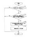
次に、図7を参照しながら、節電システム100が各種車載電子機器に対する電力供給状態を制御する処理(以下、「電力供給状態制御処理」とする。)について説明する。なお、図7は、電力供給状態制御処理の流れを示すフローチャートであり、節電システム100の制御部1は、車両の使用場面が判定できるまで、所定間隔で繰り返しこの電力供給状態制御処理を実行するものとする。 Next, a process in which the
最初に、制御部1は、使用場面判定手段10により、位置検出部2、時刻検出部3、個人認証部4、又は情報取得部5の出力に基づいて車両の使用場面を判定する(ステップS1)。 First, the
車両の使用場面が判定できない場合、制御部1は、電力供給状態制御手段11により、記憶部50に記憶された機能・機器対応マップ51(図2参照。)及び機能・場面対応マップ52(図3参照。)を参照し、使用場面「未定義」に対応する機能(本実施例では統合システムにおける全ての機能である。)を稼働状態とするための各種車載電子機器における電力モードが通常モードとなるよう、車載バッテリ又は発電機からそれら車載電子機器に電力を供給させる(ステップS2)。 When the use scene of the vehicle cannot be determined, the
一方、車両の使用場面が判定できた場合、制御部1は、電力供給状態制御手段11により、記憶部50に記憶された機能・機器対応マップ51(図2参照。)及び機能・場面対応マップ52(図3参照。)を参照し、その判定できた使用場面に対応する機能を稼働状態とするための各種車載電子機器における電力モードが通常モードとなるよう、車載バッテリ又は発電機からそれら車載電子機器に電力を供給させる(ステップS3)。 On the other hand, when the use scene of the vehicle can be determined, the
その後、制御部1は、電力供給状態記録手段12により、機器状態マップ54(図6参照。)を参照しながらの各種車載電子機器に対する電力供給状態の監視、及び、電力供給状態DB53(図5参照。)への記録を開始させる(ステップS4)。 Thereafter, the
なお、電力供給状態制御手段11は、各種車載電子機器の電力モードを切り替える度に機器状態マップ54(図6参照。)を更新するものとする。 It is assumed that the power supply state control means 11 updates the device state map 54 (see FIG. 6) every time the power mode of various in-vehicle electronic devices is switched.
次に、図8を参照しながら、節電システム100が機能・場面対応マップ52を更新する処理(以下、「機能・場面対応マップ更新処理」とする。)について説明する。なお、図8は、機能・場面対応マップ更新処理の流れを示すフローチャートであり、節電システム100の制御部1は、所定のタイミング(例えば、エンジンを始動させたときであり、電力供給状態制御処理を開始させる前である。)でこの機能・場面対応マップ更新処理を実行してもよく、電力供給状態DB53(図5参照。)に所定量のデータが蓄積された場合にこの機能・場面対応マップ更新処理を実行してもよく、或いは、使用者の求めに応じてこの機能・場面対応マップ更新処理を実行するようにしてもよい。 Next, a process in which the
最初に、制御部1は、電力供給状態学習手段13により、記憶部50に記憶された電力供給状態DB53(図5参照。)を参照して過去に記録された各使用場面における各機能の利用率を集計し且つ分析して、利用率が閾値未満(例えば、10%未満である。)となる機能が存在するか否かを判定する(ステップS11)。 First, the
利用率が閾値未満となる機能が存在しない場合(ステップS11のNO)、電力供給状態学習手段13は、機能・場面対応マップ52を更新することなく、機能・場面対応マップ更新処理を終了させる。現在の機能・場面対応マップ52の内容が過去の各運転場面における電力供給状態に合致していると判断できるからである。 When there is no function whose usage rate is less than the threshold (NO in step S11), the power supply
一方、利用率が閾値未満となる機能が存在する場合(ステップS11のYES)、電力供給状態学習手段13は、機能・機器対応マップ51(図2参照。)及び機能・場面対応マップ52(図3参照。)を参照して、利用率が閾値未満であった機能のみに関連する車載電子機器が存在するか否かを判定する(ステップS12)。 On the other hand, when there is a function whose usage rate is less than the threshold (YES in step S11), the power supply
利用率が閾値未満であった機能のみに関連する車載電子機器が存在しない場合(ステップS12のNO)、電力供給状態学習手段13は、機能・場面対応マップ52を更新することなく、機能・場面対応マップ更新処理を終了させる。現在の機能・場面対応マップ52の内容が過去の各運転場面における電力供給状態に完全に合致しているとはいえないが、利用率が閾値未満であった機能と利用率が閾値以上であった機能との双方に関連する車載電子機器(以下、「共用機器」とする。)を省電力モードとすることでその利用率が閾値以上であった機能(以下、「競合機能」とする。)をも実現できなくしてしまうという状況を避ける必要があるからである。 When there is no vehicle-mounted electronic device related only to the function whose utilization rate is less than the threshold (NO in step S12), the power supply
なお、このような場合であっても、電力供給状態学習手段13は、その共用機器の関連率(例えば、利用率が閾値未満であった三つの機能と利用率が閾値以上であった一つの機能との間の共用機器における関連率は、25%となる。)が閾値未満(例えば、30%未満、すなわち、利用率が閾値未満であった三つの機能と利用率が閾値以上であった一つの機能との間の共用機器である。)となるときには、その競合機能の利用率が低いか否かを判定するための閾値をより厳格にし(例えば、10%を20%とする。)、再度の判定によってその競合機能の利用率が低いと判定できるときには、その競合機能を非稼働状態とするようにしてもよい。 Even in such a case, the power supply state learning means 13 uses the relevance rate of the shared device (for example, three functions whose utilization rate was less than the threshold and one function whose utilization rate was equal to or greater than the threshold value). The relevance rate in the shared device between the functions is 25%) is less than the threshold (for example, less than 30%, that is, the utilization rate is less than the threshold, and the three functions and the utilization rate are greater than or equal to the threshold. The threshold for determining whether or not the utilization rate of the competing function is low (for example, 10% is set to 20%). If it can be determined that the usage rate of the competing function is low by the determination again, the competing function may be set to a non-operating state.
一方、利用率が閾値未満であった機能のみに関連する車載電子機器が存在する場合(ステップS12のYES)、電力供給状態学習手段13は、その車載電子機器の電力モードが省電力モードとなるよう機能・場面対応マップ52(図3参照。)を更新し(ステップS13)、且つ、その車載電子機器の電力モードを実際に省電力モードとした上で機器状態マップ54(図6参照。)を更新して(ステップS14)、機能・場面対応マップ更新処理を終了させる。 On the other hand, when there is an in-vehicle electronic device related only to the function whose utilization rate is less than the threshold (YES in step S12), the power supply
なお、上述の機能・場面対応マップ更新処理は、利用率の低い機能に関連する車載電子機器であり、通常モードで起動されることとなっている車載電子機器を省電力モードで起動されるように切り替える場合に適用されるが、利用率の高い機能に関連する車載電子機器であり、省電力モードで起動されることとなっている車載電子機器を通常モードで起動されるように切り替える場合に適用されてもよい。 The function / scene correspondence map update process described above is an in-vehicle electronic device related to a function with a low usage rate, and the in-vehicle electronic device that is to be activated in the normal mode is activated in the power saving mode. Applicable when switching to in-vehicle electronic devices related to high-utilization functions and switching to start in normal mode for in-vehicle electronic devices that are to be started in power saving mode May be applied.
次に、図9を参照しながら、節電システム100が非稼働状態にある機能を稼働状態に切り替える処理(以下、「稼働状態復帰処理」とする。)について説明する。なお、図9は、稼働状態復帰処理の流れを示すフローチャートであり、節電システム100の制御部1は、情報取得部5を介して使用者による統合システムに対する入力を受けた場合にこの稼働状態復帰処理を実行する。 Next, a process of switching a function in which the
最初に、制御部1は、受け付けた入力が省電力モードにある車載電子機器に関連する機能(非稼働状態の機能)に対するものであるか否かを判定する(ステップS21)。 First, the
受け付けた入力が非稼働状態の機能に対するものではない場合(ステップS21のNO)、制御部1は、そのまま稼働状態復帰処理を終了させる。 When the received input is not for the function in the non-operating state (NO in step S21), the
一方、受け付けた入力が非稼働状態の機能に対するものである場合(ステップS21のYES)、制御部1は、使用者に対して、非稼働状態にあるその機能を稼働状態に復帰させる旨の通知を行うようにする。 On the other hand, when the received input is for a non-operating function (YES in step S21), the
この場合、制御部1は、ディスプレイ20又はスピーカ21が省電力モードである場合にはそれらを一時的に通常モードとした上で、或いは、ディスプレイ20又はスピーカ21が通常モードである場合にはそのままの状態で、非稼働状態の機能を稼働状態に復帰させる旨のテキストメッセージ又は音声メッセージを使用者に対して出力する(ステップS22)。 In this case, when the
また、制御部1は、特定の機能を非稼働状態としていたことによって節約できた電力量を非稼働状態であった時間に基づいて算出し、上述の通知に加え、節約できた電力量、節約できたガソリン量、又は、削減できた二酸化炭素排出量等を通知するようにしてもよい。節電効果を使用者に伝え更なる節電を促すようにするためであり、また、非稼働状態の機能を稼働状態に復帰させるのに必要な復帰時間が使用者に与える不快感を和らげるためである。 In addition, the
その後、制御部1は、電力供給状態制御手段11により、非稼働状態の機能に関連する車載電子機器の電力モードを省電力モードから通常モードに切り替えた上で(ステップS23)、機器状態マップ54(図6参照。)を更新して(ステップS24)、この稼働状態復帰処理を終了させる。 Thereafter, the
以上の構成により、本実施例に係る節電システム100は、車両の使用場面毎に各種車載電子機器に対する電力供給状態を設定しておき、現在の使用場面に応じて各種車載電子機器に対する電力供給状態を制御するので、各種車載電子機器のそれぞれの利用状況が使用場面毎に大きく変化する場合にも柔軟に対応しながら節電を行うことができる。 With the above configuration, the
また、節電システム100は、各使用場面における各種車載電子機器に対する電力供給状態を記録し且つ分析し、今後の各使用場面における各種車載電子機器に対する最適な電力供給状態を学習して、車両の使用場面と各使用場面で利用される機能との間の対応関係を示すマップを更新するので、各使用場面における各種車載電子機器のそれぞれの利用状況が時間と共に変化する場合にも柔軟に対応しながら節電を行うことができる。 In addition, the
また、節電システム100は、各使用場面における各種車載電子機器に対する電力供給状態を記録し且つ分析し、利用率の低い車載電子機器の電力モードを省電力モードに切り替えるので、各使用場面における各種車載電子機器のそれぞれの利用率が低い場合にも柔軟に対応しながら節電を行うことができる。 Further, the
以上、本発明の好ましい実施例について詳説したが、本発明は、上述した実施例に制限されることはなく、本発明の範囲を逸脱することなく、上述した実施例に種々の変形及び置換を加えることができる。 The preferred embodiments of the present invention have been described in detail above. However, the present invention is not limited to the above-described embodiments, and various modifications and substitutions can be made to the above-described embodiments without departing from the scope of the present invention. Can be added.
例えば、上述の実施例における節電システムは、車両の使用場面に応じて各種車載電子機器に対する電力供給状態を制御する車載システムであるが、携帯電話等の他の移動体の使用場面に応じてその移動体に搭載された各種電子機器に対する電力供給状態を制御するシステムに適用されてもよい。 For example, the power saving system in the above-described embodiment is an in-vehicle system that controls the power supply state for various in-vehicle electronic devices according to the use situation of the vehicle, but according to the use situation of other mobile objects such as mobile phones. You may apply to the system which controls the electric power supply state with respect to the various electronic devices mounted in the moving body.
1 制御部
2 位置検出部
3 時刻検出部
4 個人認証部
5 情報取得部
10 使用場面判定手段
11 電力供給状態制御手段
12 電力供給状態記録手段
13 電力供給状態学習手段
20 ディスプレイ
21 スピーカ
22 オーディオユニット
23 通信モジュール
24 ETCカード読み取り機
25 画像センサ
26 距離センサ
50 記憶部
51 機能・機器対応マップ
52 機能・場面対応マップ
53 電力供給状態データベース
54 機器状態マップ
100 節電システムDESCRIPTION OF
Claims (3)
Translated fromJapanese前記複数の電子機器のそれぞれに対する電力供給状態を前記車両の使用場面毎に制御する電力供給状態制御手段と、
前記車両を始動させた場所及び日時、又は、目的地の位置情報に基づいて前記車両の使用場面を判定する使用場面判定手段と、を備え、
前記電力供給状態制御手段は、使用場面毎に設定された前記複数の電子機器のそれぞれに対する所定の電力供給状態と前記使用場面判定手段の判定結果とに基づいて前記複数の電子機器のそれぞれに対する電力供給状態を制御する、
ことを特徴とする節電システム。A power saving system that performs power saving while collectively managing a power supply state for each of the plurality of electronic devices in an integrated systemequipped with a plurality of electronic devicesmounted on a vehicle ,
Power supply state control means for controlling the power supply state for each of the plurality of electronic devices for each use scene of thevehicle ;
A location and date and time of starting the vehicle, or use scene determination means for determininga use scene of thevehicle based onlocation information of thedestination ,
The power supply state control means is configured to supply power to each of the plurality of electronic devices based on a predetermined power supply state for each of the plurality of electronic devices set for each use scene and a determination result of the use scene determination means. Control the supply status,
Power saving system characterized by that.
前記電力供給状態記録手段による記録に基づいて各使用場面における前記複数の電子機器のそれぞれの利用状況を導き出し、該利用状況に基づいて前記使用場面毎に設定された前記複数の電子機器のそれぞれに対する所定の電力供給状態を更新する電力供給状態学習手段と、
を更に備えることを特徴とする請求項1に記載の節電システム。A power supply state recording unit that monitors a power supply state for each of the plurality of electronic devices and records a power supply state for each of the plurality of electronic devices for each use scene determined by the use scene determination unit;
Based on the recording by the power supply state recording means, the usage situation of each of the plurality of electronic devices in each usage scene is derived, and for each of the plurality of electronic apparatuses set for each usage scene based on the usage situation Power supply state learning means for updating a predetermined power supply state;
The power saving system according to claim 1, further comprising:
ことを特徴とする請求項2に記載の節電システム。The power supply state learning means sets a power supply state for an electronic device having a low utilization rate to a power supply state corresponding to a power saving mode with reduced power consumption.
The power saving system according to claim 2.
Priority Applications (5)
| Application Number | Priority Date | Filing Date | Title |
|---|---|---|---|
| JP2009170567AJP5551388B2 (en) | 2009-07-21 | 2009-07-21 | Power saving system |
| PCT/IB2010/001591WO2011010197A1 (en) | 2009-07-21 | 2010-06-30 | Power-saving system and control method for the same |
| CN201080033265.1ACN102474819B (en) | 2009-07-21 | 2010-06-30 | Power-saving system and control method for the same |
| US13/386,176US8423242B2 (en) | 2009-07-21 | 2010-06-30 | Power-saving system and control method for the same |
| DE112010003036.7TDE112010003036B4 (en) | 2009-07-21 | 2010-06-30 | Energy saving system and control method for this |
Applications Claiming Priority (1)
| Application Number | Priority Date | Filing Date | Title |
|---|---|---|---|
| JP2009170567AJP5551388B2 (en) | 2009-07-21 | 2009-07-21 | Power saving system |
Publications (2)
| Publication Number | Publication Date |
|---|---|
| JP2011028338A JP2011028338A (en) | 2011-02-10 |
| JP5551388B2true JP5551388B2 (en) | 2014-07-16 |
Family
ID=42647313
Family Applications (1)
| Application Number | Title | Priority Date | Filing Date |
|---|---|---|---|
| JP2009170567AExpired - Fee RelatedJP5551388B2 (en) | 2009-07-21 | 2009-07-21 | Power saving system |
Country Status (5)
| Country | Link |
|---|---|
| US (1) | US8423242B2 (en) |
| JP (1) | JP5551388B2 (en) |
| CN (1) | CN102474819B (en) |
| DE (1) | DE112010003036B4 (en) |
| WO (1) | WO2011010197A1 (en) |
Families Citing this family (22)
| Publication number | Priority date | Publication date | Assignee | Title |
|---|---|---|---|---|
| DE102009015197A1 (en)* | 2009-03-31 | 2010-10-14 | Volkswagen Ag | Vehicle network control unit and method for operating a vehicle network |
| US8699991B2 (en)* | 2010-01-20 | 2014-04-15 | Nokia Corporation | Method and apparatus for customizing map presentations based on mode of transport |
| JP5877142B2 (en)* | 2012-09-06 | 2016-03-02 | 古河電気工業株式会社 | Power control apparatus and power control method |
| US9021431B2 (en)* | 2013-01-07 | 2015-04-28 | Abb Inc. | System and method for developing, deploying and implementing power system computer applications |
| EP2808700B1 (en)* | 2013-05-30 | 2019-10-02 | Ricoh Company, Ltd. | Drive assist device, and vehicle using drive assist device |
| CN103481841B (en)* | 2013-09-05 | 2017-10-17 | 厦门雅迅网络股份有限公司 | The energy-saving control method of onboard system |
| US9431002B2 (en) | 2014-03-04 | 2016-08-30 | Tribune Digital Ventures, Llc | Real time popularity based audible content aquisition |
| DE102014224485A1 (en)* | 2014-12-01 | 2016-06-02 | Bayerische Motoren Werke Aktiengesellschaft | Vehicle electrical system for a vehicle, corresponding vehicle and method for operating a vehicle electrical system |
| DE102014019435A1 (en)* | 2014-12-22 | 2016-06-23 | Audi Ag | Method for operating an infotainment system, infotainment system and vehicle |
| CN105068527A (en)* | 2015-07-09 | 2015-11-18 | 北汽福田汽车股份有限公司 | Electric equipment monitoring method and system of automobile |
| JP6544214B2 (en)* | 2015-11-17 | 2019-07-17 | トヨタ自動車株式会社 | Operating device |
| US10261963B2 (en) | 2016-01-04 | 2019-04-16 | Gracenote, Inc. | Generating and distributing playlists with related music and stories |
| JP2018045373A (en)* | 2016-09-13 | 2018-03-22 | 富士通株式会社 | Information processing program, information processing terminal and information processing method |
| US10565980B1 (en) | 2016-12-21 | 2020-02-18 | Gracenote Digital Ventures, Llc | Audio streaming of text-based articles from newsfeeds |
| US10419508B1 (en)* | 2016-12-21 | 2019-09-17 | Gracenote Digital Ventures, Llc | Saving media for in-automobile playout |
| US10019225B1 (en) | 2016-12-21 | 2018-07-10 | Gracenote Digital Ventures, Llc | Audio streaming based on in-automobile detection |
| US11042138B2 (en)* | 2018-10-09 | 2021-06-22 | Johnson Controls Technology Company | Auto detection of signature and native reference changes from data sources |
| CN111301323A (en)* | 2020-03-04 | 2020-06-19 | 沈阳天眼智云信息科技有限公司 | Comprehensive energy-saving consumption-reducing method for intelligent monitoring terminal |
| CN112732341B (en)* | 2020-11-30 | 2023-08-01 | 北京百度网讯科技有限公司 | Dormancy control method, device and readable storage medium for vehicle-mounted computing platform |
| CN112721730A (en)* | 2021-01-07 | 2021-04-30 | 广州橙行智动汽车科技有限公司 | Vehicle power management method and device, vehicle and storage medium |
| CN114537307A (en)* | 2022-02-25 | 2022-05-27 | 重庆长安新能源汽车科技有限公司 | Intelligent power management method for new energy automobile |
| CN116424246A (en)* | 2023-05-10 | 2023-07-14 | 长城汽车股份有限公司 | Vehicle energy-saving method, device, vehicle and storage medium |
Family Cites Families (28)
| Publication number | Priority date | Publication date | Assignee | Title |
|---|---|---|---|---|
| DE69006885T3 (en)* | 1989-04-14 | 1999-05-20 | Hitachi, Ltd., Tokio/Tokyo | Control device for cars. |
| WO1999026330A2 (en)* | 1997-11-17 | 1999-05-27 | Lifestyle Technologies | Universal power supply |
| JP2000215100A (en) | 1999-01-21 | 2000-08-04 | Nec Corp | Power-saving memory management system |
| FR2805782B1 (en)* | 2000-03-01 | 2003-06-20 | Renault Vehicules Ind | ENERGY MANAGEMENT DEVICE FOR VEHICLE |
| GB2373887A (en)* | 2001-03-28 | 2002-10-02 | Hewlett Packard Co | Context dependent operation, including power management, of a mobile computer |
| JP3600556B2 (en)* | 2001-06-29 | 2004-12-15 | 株式会社東芝 | Information processing equipment |
| US7080267B2 (en)* | 2002-08-01 | 2006-07-18 | Texas Instruments Incorporated | Methodology for managing power consumption in an application |
| CN100481786C (en)* | 2002-08-09 | 2009-04-22 | 爱信艾达株式会社 | Power management system for communication device |
| JP4063195B2 (en) | 2002-11-08 | 2008-03-19 | 株式会社デンソー | In-vehicle communication device |
| US20050228553A1 (en)* | 2004-03-30 | 2005-10-13 | Williams International Co., L.L.C. | Hybrid Electric Vehicle Energy Management System |
| US20050239518A1 (en)* | 2004-04-21 | 2005-10-27 | D Agostino Anthony | Systems and methods that provide enhanced state machine power management |
| JP2005332203A (en)* | 2004-05-20 | 2005-12-02 | Mitsubishi Electric Corp | Power supply circuit and portable information device |
| JP2006029961A (en)* | 2004-07-15 | 2006-02-02 | Seiko Epson Corp | Mobile terminal, mobile terminal control program, and computer-readable recording medium recording the mobile terminal control program |
| US7565562B2 (en)* | 2004-09-03 | 2009-07-21 | Intel Corporation | Context based power management |
| JP2006208304A (en)* | 2005-01-31 | 2006-08-10 | Clarion Co Ltd | Navigation system, its method, and program |
| JP2006236532A (en) | 2005-02-28 | 2006-09-07 | Toshiba Corp | Electronic device and power consumption control method thereof |
| JP2006330843A (en) | 2005-05-23 | 2006-12-07 | Ricoh Co Ltd | Information equipment |
| JP5040139B2 (en)* | 2006-03-30 | 2012-10-03 | アイシン・エィ・ダブリュ株式会社 | Power management system |
| JP2007323137A (en)* | 2006-05-30 | 2007-12-13 | Funai Electric Co Ltd | Electronic device system and controller |
| JP4400599B2 (en)* | 2006-08-03 | 2010-01-20 | トヨタ自動車株式会社 | Vehicle control system |
| US20080070652A1 (en)* | 2006-09-18 | 2008-03-20 | Igt, Inc. | Reduced power consumption wager gaming machine |
| US8323087B2 (en)* | 2006-09-18 | 2012-12-04 | Igt | Reduced power consumption wager gaming machine |
| JP2008197812A (en)* | 2007-02-09 | 2008-08-28 | Toshiba Corp | Information processing device |
| JP5169075B2 (en)* | 2007-08-27 | 2013-03-27 | 株式会社リコー | Power management system, management device, power management method, power management program, and recording medium for recording power management program |
| US8255090B2 (en)* | 2008-02-01 | 2012-08-28 | Energyhub | System and method for home energy monitor and control |
| US8339069B2 (en)* | 2008-04-14 | 2012-12-25 | Digital Lumens Incorporated | Power management unit with power metering |
| GB0816721D0 (en)* | 2008-09-13 | 2008-10-22 | Daniel Simon R | Systems,devices and methods for electricity provision,usage monitoring,analysis and enabling improvements in efficiency |
| WO2010104521A1 (en)* | 2009-03-13 | 2010-09-16 | Hewlett-Packard Development Company, L.P. | Determining status assignments that optimize entity utilization and resource power consumption |
- 2009
- 2009-07-21JPJP2009170567Apatent/JP5551388B2/ennot_activeExpired - Fee Related
- 2010
- 2010-06-30CNCN201080033265.1Apatent/CN102474819B/ennot_activeExpired - Fee Related
- 2010-06-30USUS13/386,176patent/US8423242B2/ennot_activeExpired - Fee Related
- 2010-06-30DEDE112010003036.7Tpatent/DE112010003036B4/ennot_activeExpired - Fee Related
- 2010-06-30WOPCT/IB2010/001591patent/WO2011010197A1/enactiveApplication Filing
Also Published As
| Publication number | Publication date |
|---|---|
| DE112010003036B4 (en) | 2015-02-05 |
| JP2011028338A (en) | 2011-02-10 |
| US8423242B2 (en) | 2013-04-16 |
| WO2011010197A1 (en) | 2011-01-27 |
| DE112010003036T5 (en) | 2013-04-18 |
| CN102474819A (en) | 2012-05-23 |
| CN102474819B (en) | 2014-08-13 |
| US20120123639A1 (en) | 2012-05-17 |
Similar Documents
| Publication | Publication Date | Title |
|---|---|---|
| JP5551388B2 (en) | Power saving system | |
| CN110660259B (en) | Parking prompting method and device, electronic equipment and readable medium | |
| JP6258375B2 (en) | Vehicle monitoring system, electronic device and vehicle monitoring method | |
| US20110035137A1 (en) | Vehicle operation diagnostic device, vehicle operation diagnostic method, and computer program | |
| JP6160364B2 (en) | Map information update system, map information update device, map information update method, and computer program | |
| JP2011103115A (en) | In-vehicle navigation apparatus | |
| US7693656B2 (en) | Navigation apparatus | |
| JP2011051376A (en) | On-vehicle electronic apparatus | |
| JP2014067086A (en) | Drive recorder | |
| JP5298074B2 (en) | In-vehicle device and navigation device control method | |
| JP3862564B2 (en) | Digital operation record system | |
| JP4848428B2 (en) | Information notification device, information notification method, information notification program, and recording medium | |
| JP2019113421A (en) | Guide system and guide program | |
| JPH0765285A (en) | Vehicle information provision device | |
| US20240177604A1 (en) | Location information output method, location information output system, and program | |
| JP2008026241A (en) | On-vehicle navigation system | |
| JP2013054697A (en) | On-vehicle device and positional information acquisition method for the same | |
| JP2012145376A (en) | Navigation device, navigation method and information management server | |
| JP2004206614A (en) | Operation method of running history collection system | |
| JP2012145440A (en) | Facility guiding device, facility guiding method and computer program | |
| JP5005282B2 (en) | Theft detection device, method and program for navigation device | |
| CN110892229B (en) | Notification control device and notification control method | |
| JP2007272489A (en) | Driving support device | |
| JP4289296B2 (en) | Guide device and program | |
| JP4308901B2 (en) | Vehicle communication device power management system and navigation device using the same |
Legal Events
| Date | Code | Title | Description |
|---|---|---|---|
| A621 | Written request for application examination | Free format text:JAPANESE INTERMEDIATE CODE: A621 Effective date:20120615 | |
| A977 | Report on retrieval | Free format text:JAPANESE INTERMEDIATE CODE: A971007 Effective date:20130510 | |
| A131 | Notification of reasons for refusal | Free format text:JAPANESE INTERMEDIATE CODE: A131 Effective date:20130604 | |
| A521 | Written amendment | Free format text:JAPANESE INTERMEDIATE CODE: A523 Effective date:20130628 | |
| A131 | Notification of reasons for refusal | Free format text:JAPANESE INTERMEDIATE CODE: A131 Effective date:20131119 | |
| A521 | Written amendment | Free format text:JAPANESE INTERMEDIATE CODE: A523 Effective date:20131225 | |
| TRDD | Decision of grant or rejection written | ||
| A01 | Written decision to grant a patent or to grant a registration (utility model) | Free format text:JAPANESE INTERMEDIATE CODE: A01 Effective date:20140430 | |
| A61 | First payment of annual fees (during grant procedure) | Free format text:JAPANESE INTERMEDIATE CODE: A61 Effective date:20140522 | |
| R250 | Receipt of annual fees | Free format text:JAPANESE INTERMEDIATE CODE: R250 | |
| LAPS | Cancellation because of no payment of annual fees |