JP5551281B2 - Method and apparatus for high speed other sector interference (OSI) coordination - Google Patents
Method and apparatus for high speed other sector interference (OSI) coordinationDownload PDFInfo
- Publication number
- JP5551281B2 JP5551281B2JP2013003942AJP2013003942AJP5551281B2JP 5551281 B2JP5551281 B2JP 5551281B2JP 2013003942 AJP2013003942 AJP 2013003942AJP 2013003942 AJP2013003942 AJP 2013003942AJP 5551281 B2JP5551281 B2JP 5551281B2
- Authority
- JP
- Japan
- Prior art keywords
- interference
- osi
- average
- value
- metric
- Prior art date
- Legal status (The legal status is an assumption and is not a legal conclusion. Google has not performed a legal analysis and makes no representation as to the accuracy of the status listed.)
- Expired - Fee Related
Links
- 238000000034methodMethods0.000titleclaimsdescription84
- 238000004891communicationMethods0.000claimsdescription105
- 230000006870functionEffects0.000claimsdescription35
- 238000005259measurementMethods0.000claimsdescription33
- 238000009826distributionMethods0.000claimsdescription15
- 238000011156evaluationMethods0.000claimsdescription8
- 238000012935AveragingMethods0.000claimsdescription6
- 230000001186cumulative effectEffects0.000claimsdescription5
- 238000005315distribution functionMethods0.000claimsdescription5
- 230000005540biological transmissionEffects0.000description38
- 230000002441reversible effectEffects0.000description25
- 238000010586diagramMethods0.000description19
- 238000013459approachMethods0.000description17
- 238000007726management methodMethods0.000description17
- 230000000875corresponding effectEffects0.000description15
- 230000004044responseEffects0.000description15
- 238000004422calculation algorithmMethods0.000description14
- 239000011159matrix materialSubstances0.000description12
- 238000004364calculation methodMethods0.000description10
- 230000008569processEffects0.000description10
- 238000013468resource allocationMethods0.000description9
- 230000008901benefitEffects0.000description7
- 230000007774longtermEffects0.000description6
- 238000012544monitoring processMethods0.000description6
- 230000003595spectral effectEffects0.000description5
- 230000007423decreaseEffects0.000description4
- 238000012545processingMethods0.000description4
- 239000000969carrierSubstances0.000description3
- 230000000694effectsEffects0.000description3
- 230000000737periodic effectEffects0.000description3
- 230000010363phase shiftEffects0.000description3
- 239000002096quantum dotSubstances0.000description3
- 230000007704transitionEffects0.000description3
- 238000004458analytical methodMethods0.000description2
- 238000013500data storageMethods0.000description2
- 230000003247decreasing effectEffects0.000description2
- 238000005516engineering processMethods0.000description2
- 230000000670limiting effectEffects0.000description2
- 238000012423maintenanceMethods0.000description2
- 230000000116mitigating effectEffects0.000description2
- 238000006467substitution reactionMethods0.000description2
- 230000001360synchronised effectEffects0.000description2
- 241000084490Esenbeckia deltaSpecies0.000description1
- 238000005481NMR spectroscopyMethods0.000description1
- 230000002411adverseEffects0.000description1
- 230000004075alterationEffects0.000description1
- 230000001413cellular effectEffects0.000description1
- 230000008859changeEffects0.000description1
- 239000003795chemical substances by applicationSubstances0.000description1
- 230000000295complement effectEffects0.000description1
- 238000012790confirmationMethods0.000description1
- 239000000470constituentSubstances0.000description1
- 230000002596correlated effectEffects0.000description1
- 238000009795derivationMethods0.000description1
- 230000005670electromagnetic radiationEffects0.000description1
- 230000003993interactionEffects0.000description1
- 238000012986modificationMethods0.000description1
- 230000004048modificationEffects0.000description1
- 238000004651near-field scanning optical microscopyMethods0.000description1
- 238000005192partitionMethods0.000description1
- NRNCYVBFPDDJNE-UHFFFAOYSA-NpemolineChemical compoundO1C(N)=NC(=O)C1C1=CC=CC=C1NRNCYVBFPDDJNE-UHFFFAOYSA-N0.000description1
- 230000009467reductionEffects0.000description1
- 230000011664signalingEffects0.000description1
- 230000009897systematic effectEffects0.000description1
- 230000036962time dependentEffects0.000description1
- 230000001131transforming effectEffects0.000description1
Images


Classifications
- H—ELECTRICITY
- H04—ELECTRIC COMMUNICATION TECHNIQUE
- H04W—WIRELESS COMMUNICATION NETWORKS
- H04W72/00—Local resource management
- H04W72/50—Allocation or scheduling criteria for wireless resources
- H04W72/54—Allocation or scheduling criteria for wireless resources based on quality criteria
- H04W72/541—Allocation or scheduling criteria for wireless resources based on quality criteria using the level of interference
- H—ELECTRICITY
- H04—ELECTRIC COMMUNICATION TECHNIQUE
- H04W—WIRELESS COMMUNICATION NETWORKS
- H04W72/00—Local resource management
- H04W72/04—Wireless resource allocation
- H04W72/044—Wireless resource allocation based on the type of the allocated resource
- H04W72/0446—Resources in time domain, e.g. slots or frames
- H—ELECTRICITY
- H04—ELECTRIC COMMUNICATION TECHNIQUE
- H04W—WIRELESS COMMUNICATION NETWORKS
- H04W72/00—Local resource management
- H04W72/04—Wireless resource allocation
- H04W72/044—Wireless resource allocation based on the type of the allocated resource
- H04W72/0453—Resources in frequency domain, e.g. a carrier in FDMA
- H—ELECTRICITY
- H04—ELECTRIC COMMUNICATION TECHNIQUE
- H04W—WIRELESS COMMUNICATION NETWORKS
- H04W72/00—Local resource management
- H04W72/20—Control channels or signalling for resource management
- H04W72/23—Control channels or signalling for resource management in the downlink direction of a wireless link, i.e. towards a terminal
Landscapes
- Engineering & Computer Science (AREA)
- Computer Networks & Wireless Communication (AREA)
- Signal Processing (AREA)
- Quality & Reliability (AREA)
- Mobile Radio Communication Systems (AREA)
Description
Translated fromJapanese本出願は、2006年9月8日に提出された米国仮出願第60/843,291号、および2007年9月4日に提出された米国特許出願第11/849,595号の利益を主張する。本出願の全体は、参照することによりここに組み込まれる。 This application claims the benefit of US Provisional Application No. 60 / 843,291, filed September 8, 2006, and US Patent Application No. 11 / 849,595, filed September 4, 2007. To do. The entirety of this application is hereby incorporated by reference.
本開示は、一般に無線通信に関し、特に、無線通信システムにおける高速他セクタ干渉および通信リソース調整のための技術に関する。 The present disclosure relates generally to wireless communication, and more particularly to techniques for high-speed other sector interference and communication resource adjustment in a wireless communication system.
無線通信は、個人の日々の仕事のほぼすべての局面に浸透している。仕事/オフィス活動ならびにエンターテイメントを円滑化するために、無線システムは広く展開し、音声、データ、映像などのような種々の型の通信コンテンツを提供する。これらのシステムは、利用可能システムリソースの共有により複数の端末のための通信をサポート可能な多元接続システムとすることができる。そのような多元接続システムの例は符号分割多元接続(CDMA)システム、時分割多元接続(TDMA)システム、周波数分割多元接続(FDMA)システムおよび直交周波数分割多元接続(OFDMA)システムを含む。 Wireless communication has permeated almost every aspect of an individual's daily work. In order to facilitate work / office activities as well as entertainment, wireless systems are widely deployed to provide various types of communication content such as voice, data, video, and the like. These systems can be multi-access systems that can support communication for multiple terminals by sharing available system resources. Examples of such multiple access systems include code division multiple access (CDMA) systems, time division multiple access (TDMA) systems, frequency division multiple access (FDMA) systems, and orthogonal frequency division multiple access (OFDMA) systems.
無線多元接続通信システムは、複数の無線端末のための通信を同時にサポートすることができる。そのようなシステムでは、端末はそれぞれフォワードリンクおよびリバースリンク上の送信によって1つまたは複数のセクタと通信することができる。フォワードリンク(つまりダウンリンク)はセクタから端末への通信リンクのことをいう。また、リバースリンク(つまりアップリンク)は端末からセクタへの通信リンクのことをいう。これらの通信リンクは単入力単出力(SISO)、多入力単出力(MISO)、および/または多入力多出力(MIMO)システムによって開設することができる。 A wireless multiple-access communication system can simultaneously support communication for multiple wireless terminals. In such a system, a terminal can communicate with one or more sectors via transmissions on the forward and reverse links, respectively. The forward link (or downlink) refers to the communication link from the sector to the terminal. The reverse link (that is, the uplink) refers to a communication link from the terminal to the sector. These communication links can be established by single input single output (SISO), multiple input single output (MISO), and / or multiple input multiple output (MIMO) systems.
複数の端末は、時間、周波数および/または符号領域で互いに直角となるように送信を多重化することにより、リバースリンク上で同時に送信することができる。送信間の十分な直交性が達成されれば、各端末からの送信は、受信セクタでの他の端末からの送信に干渉しない。しかし、チャネル条件、受信機不完全性および他の要因により、異なる端末からの送信の間の完全な直交性が実現されないことがある。その結果、端末は、同じセクタと通信する他の端末に対して若干の干渉を引き起こす。更に、異なるセクタと通信する端末からの送信は、典型的には互いに直角ではないことから、各端末が近傍セクタと通信する端末への干渉を引き起こす場合もある。この干渉は、当該システムにおける各端末の性能の低下をもたらす。従って、当該技術分野においては、無線通信システムにおける干渉の影響を緩和するための有効な技術が必要とされている。 Multiple terminals can transmit simultaneously on the reverse link by multiplexing the transmissions to be orthogonal to one another in time, frequency and / or code domain. If sufficient orthogonality between transmissions is achieved, transmissions from each terminal do not interfere with transmissions from other terminals in the receiving sector. However, due to channel conditions, receiver imperfections and other factors, perfect orthogonality between transmissions from different terminals may not be achieved. As a result, the terminal causes some interference to other terminals communicating with the same sector. Furthermore, transmissions from terminals communicating with different sectors are typically not at right angles to each other, so each terminal may cause interference to terminals communicating with neighboring sectors. This interference causes a decrease in the performance of each terminal in the system. Accordingly, there is a need in the art for effective techniques for mitigating the effects of interference in wireless communication systems.
下記は開示された実施形態のいくつかの態様の基本的了解事項を提供するために単純化された要約を示す。この要約は広範囲な概観ではなく、重要または重大な構成要素を同定することや、かかる実施形態の範囲を線引きすることは意図されていない。その目的は、後に示されるより詳細な説明の前ぶれとして、記載された実施形態のいくつかの概念を簡素なかたちで示すことにある。 The following presents a simplified summary in order to provide a basic understanding of some aspects of the disclosed embodiments. This summary is not an extensive overview and is not intended to identify key or critical components or to delineate the scope of such embodiments. Its purpose is to present some concepts of the described embodiments in a simplified form as a prelude to the more detailed description that is presented later.
ある態様では、無線システムにおけるリソース管理が開示される。この方法は、他セクタ干渉(OSI)の指標を受信すること;通信リソースに関連付けられたデルタ値が前記受信したOSI指標に応じて調整されるべきかどうか決定すること、該決定は前記OSI指標に対応する時間周波数リソースを同定することを含む;および前記通信リソースに関連付けられた前記デルタ値を調整することを含む。 In an aspect, resource management in a wireless system is disclosed. The method receives an indicator of other sector interference (OSI); determines whether a delta value associated with a communication resource is to be adjusted according to the received OSI indicator, the determination is the OSI indicator Identifying a time-frequency resource corresponding to the; and adjusting the delta value associated with the communication resource.
別の態様において、本件明細書は無線通信装置を開示する。この装置は、アクセスポイントのセットを取得し、取得したアクセスポイントのセット内のアクセスポイントから超過他セクタ干渉(OSI)の指標を受信し、前記超過OSI指標に従って通信リソースに関連付けられたオフセット値を調整し、前記調整したオフセット値保持するように構成された集積回路;およびデータを格納するための前記集積回路に結合されたメモリを具備する。 In another aspect, this specification discloses a wireless communication device. The apparatus acquires a set of access points, receives an indicator of excess other sector interference (OSI) from access points in the acquired set of access points, and determines an offset value associated with a communication resource according to the excess OSI indicator. An integrated circuit configured to adjust and retain the adjusted offset value; and a memory coupled to the integrated circuit for storing data.
さらに別の態様では、無線通信システムにおけるリソース管理を容易にする装置は、非サービングアクセスポイント(AP)のセットを設定して他セクタ干渉指標を監視するための手段;前記監視セット内の1つまたは複数のAPから他セクタ干渉(OSI)指標を受信するための手段;および前記受信したOSI指標に従って通信リソースに関連付けられたオフセット値を調整するための手段を具備する。 In yet another aspect, an apparatus for facilitating resource management in a wireless communication system comprises means for configuring a set of non-serving access points (APs) to monitor other sector interference indicators; one in the monitoring set Or means for receiving other sector interference (OSI) indications from a plurality of APs; and means for adjusting an offset value associated with a communication resource in accordance with the received OSI indications.
さらに別の態様では、コンピュータ可読媒体は、コンピュータに、非サービングアクセスポイントのセットから超過他セクタ干渉の指標を受信させるためのコード;コンピュータに、アクセスポイントによって割当てられた通信リソースに関連付けられたオフセット値を調整させるためのコード;コンピュータに、次のリソース割当てを更新するためにアクセスポイントに前記調整したオフセット値を伝えさせるためのコードを具備する。 In yet another aspect, a computer-readable medium is code for causing a computer to receive an indication of excess other sector interference from a set of non-serving access points; an offset associated with communication resources allocated by the access point to the computer Code for adjusting the value; code for causing the computer to communicate the adjusted offset value to the access point to update the next resource allocation.
ある態様では、無線システムにおける干渉を管理する方法は、干渉メトリックに基づいて干渉レベルを決定すること;前記決定した干渉レベルに基づいた他セクタ干渉(OSI)の指標を生成すること;および前記OSI指標を送信することを含む。 In an aspect, a method for managing interference in a wireless system includes determining an interference level based on an interference metric; generating an indicator of other sector interference (OSI) based on the determined interference level; and the OSI Including sending indicators.
別の態様において、無線通信に用いられる装置は、干渉メトリックに基づいて高速干渉レベルを決定するための手段;高速他セクタ干渉(OSI)の指標を前記高速干渉レベルに従って生成するための手段;および前記生成したOSI指標を送信するための手段を具備する。 In another aspect, an apparatus used for wireless communication comprises: means for determining a high speed interference level based on an interference metric; means for generating a high speed other sector interference (OSI) indication according to the high speed interference level; and Means are provided for transmitting the generated OSI indicator.
さらに別の態様では、コンピュータ可読媒体は、フレーム時間スケールとスーパーフレーム時間スケール上の干渉レベル(無線システムのシンボルニューメロロジーによって規定された時間スケール)をコンピュータに測定させるためのコード;コンピュータに、前記干渉レベル測定に基づいて有効干渉レベルを計算させるためのコード;および超過他セクタ干渉指標を前記計算された有効干渉レベルに従ってコンピュータに発行させるためのコードを具備する。 In yet another aspect, a computer-readable medium comprises code for causing a computer to measure an interference level on a frame time scale and a superframe time scale (a time scale defined by the symbolic neurology of a wireless system); Code for causing an effective interference level to be calculated based on the interference level measurement; and code for causing a computer to issue an excess other sector interference indicator according to the calculated effective interference level.
さらに別の態様では、無線通信環境において動作する電気機器は、周波数領域と時間領域において干渉レベルを測定し、該測定は異種の時間スケールで行なわれ、低速および高速レジームにおける前記測定の結果を用いる有効干渉レベルを計算し、超過他セクタ干渉の指標をブロードキャストするように構成された集積回路;および測定され計算されたデータを格納する前記集積回路に結合されたメモリを具備する。 In yet another aspect, electrical equipment operating in a wireless communication environment measures interference levels in the frequency domain and the time domain, where the measurements are made on disparate time scales and use the results of the measurements in the slow and fast regimes. An integrated circuit configured to calculate an effective interference level and broadcast an indication of excess other sector interference; and a memory coupled to the integrated circuit storing measured and calculated data.
さらに別の態様は、無線通信を容易にする装置であって、該システムは、リソース割当てを送信し、割当てられたリソースに関連付けられた調整オフセット値を受信するように構成された構成された集積回路;およびデータを格納するための前記集積回路に結合されたメモリを具備し、該データは、通信リソースに関連したオフセットの調整された値を含む。 Yet another aspect is an apparatus that facilitates wireless communication, wherein the system is configured to transmit a resource assignment and receive an adjustment offset value associated with the assigned resource. A memory coupled to the integrated circuit for storing data, the data including an adjusted value of an offset associated with a communication resource.
上述の関連する目的を達成するために、1つまたは複数の実施形態は、以下で十分に記載され、特許請求の範囲において特に指摘された特徴を具備する。 To the accomplishment of the related objectives described above, one or more embodiments comprise the features fully described below and particularly pointed out in the claims.
以下の明細書および添付の図面は、ある例示の態様を詳細に説明しており、実施形態の原理を採用できるさまざまな方法を、いくつか示している。 The following specification and the annexed drawings set forth in detail certain illustrative aspects and illustrate some of the various ways in which the principles of the embodiments may be employed.
以下の詳細な説明を図面と共に検討すれば、他の利点および新規な特徴が明らかになるであろう。また開示された実施形態は、かかる態様およびその等価物のすべてを含むことが意図されている。 Other advantages and novel features will become apparent from the following detailed description when considered in conjunction with the drawings. Also, the disclosed embodiments are intended to include all such aspects and their equivalents.
種々の実施形態を図面を参照して説明する。ここでは、全体にわたって構成要素等を参照するために参照数字等を用いる。以下の明細書には、1つまたは複数の実施形態の一通りの理解が得られるように、説明を目的として幾多の具体的詳細が記載される。しかしながら、これら具体的詳細が無くとも、かかる実施形態を実施できることは明らかであろう。その他の例において、良く知られた構造および装置については、1つまたは複数の実施形態の説明を容易にするために、ブロック図の形式で示す。 Various embodiments will be described with reference to the drawings. Here, reference numerals and the like are used to refer to constituent elements and the like throughout. In the following specification, for the purposes of explanation, numerous specific details are set forth in order to provide a thorough understanding of one or more embodiments. However, it will be apparent that such embodiments may be practiced without these specific details. In other instances, well-known structures and devices are shown in block diagram form in order to facilitate describing one or more embodiments.
さらに、用語「または(or)」は、排他的な「または」よりもむしろ、包括的な「または」を意味することが意図される。すなわち、別段の指定がないまたは文脈から明らかでない限り、「xはAまたはBを用いる」とは、自然な包括的置換のいずれかを意味することが意図される。すなわち、xがAを用いるか、xがBを用いるか、それともxがAとBの両方を用いるならば、このような例のいずれかに基づいて「xはAまたはBを用いる」が充足される。さらに、このapplicationおよび添付のclaimsにおいて用いられるような冠詞「a」および「an」は、別段の指定がない、または単数形が意図されていることが文脈から明らかでない限り「1つまたは複数」を意味すると一般的に解釈されるべきである。 Further, the term “or” is intended to mean an inclusive “or” rather than an exclusive “or”. That is, unless otherwise specified or apparent from the context, “x uses A or B” is intended to mean any of the natural global substitutions. That is, if x uses A, x uses B, or x uses both A and B, then “x uses A or B” based on any of these examples Is done. Further, the articles “a” and “an” as used in this application and the appended claims are intended to be “one or more” unless the context clearly indicates otherwise. Should be generally interpreted as meaning.
本願明細書で用いるような「コンポーネント」、「モジュール」、「システム」などの用語は、コンピュータ関連の実体、すなわちハードウェア、ファームウェア、ハードウェアとソフトウェアの組み合わせ、ソフトウェアまたは実行中のソフトウェアのいずれかを指すことが意図される。例えば、コンポーネントはプロセッサ上の実行プロセス、プロセッサ、オブジェクト、実行ファイル、実行スレッド、プログラム、および/またはコンピュータであってもよいが、これらに限定されるものではない。実例として、コンピューティング装置上で実行するアプリケーション、およびコンピューティング装置は、ともにコンポーネントとすることができる。1つまたは複数のコンポーネントがプロセスおよび/または実行スレッド内に存在することができ、あるコンポーネントを1つのコンピュータに配置し、および/または2台以上のコンピュータに分散配置してもよい。さらに、これらのコンポーネントは、諸データ構造を格納する種々のコンピュータ読取り可能な媒体から実行してもよい。該コンポーネントは、ローカルプロセスおよび/またはリモートプロセスとして、例えば1つまたは複数のデータパケット(例えば、ローカルシステム、分散型システムにおける別のコンポーネントと相互作用するコンポーネントからのデータ、インターネットのようなネットワークを経由する信号を手段として他システムと相互作用するコンポーネントからのデータ)を有する信号に従って通信を行ってもよい。 As used herein, the terms "component", "module", "system", etc. are either computer-related entities, ie, hardware, firmware, a combination of hardware and software, software or running software Is intended to refer to. For example, a component may be, but is not limited to being, an execution process on a processor, a processor, an object, an execution file, an execution thread, a program, and / or a computer. By way of illustration, both an application running on a computing device and the computing device can be a component. One or more components can exist within a process and / or thread of execution, and a component can be located on one computer and / or distributed across two or more computers. In addition, these components may execute from various computer readable media that store data structures. The component may be a local process and / or a remote process, eg, one or more data packets (eg, data from a component interacting with another component in a local system, distributed system, via a network such as the Internet The communication may be performed according to a signal having data from a component that interacts with another system using the signal as a means.
更にここでは、モバイル装置に関連して種々の実施形態を説明する。モバイル装置は、システム、加入者ユニット、加入者局、移動局、モバイル、リモート局、リモート端末、アクセス端末、ユーザ端末、端末、無線通信装置、ユーザエージェント、ユーザ装置またはユーザ機器(UE)と呼ぶことができる。モバイル装置は、携帯電話機、コードレス電話機、セッション設定プロトコル(SIP)電話機、ワイヤレスローカルループ(WLL)局、携帯情報端末(PDA)、無線接続能力を持っているハンドヘルド装置、コンピューティング装置または無線モデムに接続された他の制御演算装置であってもよい。ここで、基地局に関連して種々の実施形態を説明する。基地局はモバイル装置との通信のために利用することができ、アクセスポイント、ノードB、エボルブドノードB(eNodeB)または他のある用語で称することができる。 Furthermore, various embodiments are described herein in connection with a mobile device. A mobile device is called system, subscriber unit, subscriber station, mobile station, mobile, remote station, remote terminal, access terminal, user terminal, terminal, wireless communication device, user agent, user device or user equipment (UE). be able to. Mobile devices include mobile phones, cordless phones, session setup protocol (SIP) phones, wireless local loop (WLL) stations, personal digital assistants (PDAs), handheld devices with wireless connectivity, computing devices or wireless modems. It may be another connected control arithmetic device. Various embodiments will now be described in connection with a base station. A base station can be utilized for communication with mobile devices and can be referred to as an access point, Node B, evolved Node B (eNodeB), or some other terminology.
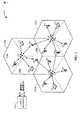
ここで図面を参照すると、図1は種々の態様による無線多元接続通信システム100の図である。ある例では、無線多元接続通信システム100は複数の基地局110および複数の端末120を含んでいる。さらに、1つまたは複数の基地局110は1つまたは複数の端末120と通信することができる。限定されない例として、基地局110は、アクセスポイントであり、ノードBおよび/または別の適合するネットワークエンティティーであってもよい。各基地局110は特定の地理的なエリア102aーcに通信カバレッジを供給する。一般に当該技術分野で用いられ、またここで用いられるように、用語「セル」は基地局110および/または用語が用いられるコンテキストに依存するそのカバレッジエリア102acのことをいう。 Referring now to the drawings, FIG. 1 is an illustration of a wireless multiple-
システムキャパシティを向上するために、基地局110に対応するカバレッジエリア102a、102bまたは102cは、複数のより小さなエリア(例えばエリア104a、104bおよび104c)に分割することができる。より小さなエリア104a、104bおよび104cの各々を、それぞれのベーストランシーバーサブシステム(図示しないBTS)がサーブしてもよい。一般に当該技術分野で用いられ、またここで用いられるように、用語「セクタ」は、該用語が用いられるコンテキストに依存し、BTSおよび/またはそのカバレッジエリアのことであるといえる。ある例では、セル102a、102bまたは102c内のセクタ104a、104bおよび104cは、基地局110においてアンテナのグループ(図示しない)によって形成することができ、各アンテナのグループは、セル102a、102bまたは102cの一部における端末120との通信を担う。例えば、セル102aをサーブする基地局110は、セクタ104aに対応する第一のアンテナグループを持ち、セクタ104bに対応する第二のアンテナグループを持ち、セクタ104cに対応する第三のアンテナグループを持ってもよい。また一方、ここに開示された種々の態様は、セクタ化セルおよび/または非セクタ化セルを持つシステムにおいて用いることができることを理解されたい。さらに、いかなる数のセクタ化セルおよび/または非セクタ化セルを持つものであっても、適合する無線通信ネットワークはすべて、添付の特許請求の範囲に含まれることが意図される点を理解されたい。単純化のために、ここで用いられる用語「基地局」とは、セルをサーブする局ならびにセクタをサーブする局の両者を指すことができる。さらに、ここでは、「サービング」アクセスポイントとは、端末がRLトラフィック(データ)送信をしているものをいい、「隣接」(非サービング)アクセスポイントは、端末がFLトラフィックを持つことができるもの、および/またはFLおよびRL制御送信の両者を持つがRLトラフィックを持たないものをいう。ここで用いるような、リンクがバラバラであるシナリオにおけるFLセクタは、隣接セクタであることを理解されたい。以下の説明は、簡単化のために、大まかには各端末が1つのサービングアクセスポイントと通信するシステムに関するものであるが、端末はいかなる数のサービングアクセスポイントとも通信することができることを理解されたい。 To improve system capacity, the
ある態様に従って、端末120はシステム100の全体にわたって分散することができる。各端末120は固定のものまたはモバイルとすることができる。限定されない例として、端末120は、アクセス端末(AT)、移動局、ユーザ機器、加入者局および/または別の適合するネットワークエンティティーになりえる。端末120は、無線装置、携帯電話、携帯情報端末(PDA)、無線モデム、ハンドヘルド装置または別の適合する装置になりえる。さらに、端末120は、任意の数の基地局110と通信することができ、または任意のある時期では基地局110と通信できない。 In accordance with an aspect, the
別の例では、システム100は、1つまたは複数の基地局110につなぐことができ、基地局110に調整と制御を供給することができるシステム・コントローラ130を用いることにより、集中型のアーキテクチャを利用することができる。代替態様に従って、システム・コントローラ130は単一のネットワークエンティティーまたはネットワークエンティティーの集合になりえる。さらに、システム100は、基地局110が必要に応じて互いと通信することを可能にするために分散型アーキテクチャを利用することができる。ある例では、システム・コントローラ130は、さらに複数のネットワークへの1つまたは複数の接続を収容することができる。これらのネットワークは、インターネット、他のパケットベースのネットワーク、および/またはシステム100における1つまたは複数の基地局110と通信する端末120への情報および/または該端末120からの情報を提供できる回線交換音声ネットワークを含んでも良い。別の例では、システム・コントローラ130は、端末120への送信および/または同端末120からの送信をスケジューリングすることのできるスケジューラを含んでもよく、または同スケジューラに接続されてもよい。あるいは、スケジューラは、各々独立したセル102a−c、各セクタ104a−c、またはそれらの組み合わせの中に存在してもよい。 In another example, the
ある例では、システム100は、CDMA、TDMA、FDMA、OFDMA、シングルキャリアFDMA(SC−FDMA)および/または他の適合する多元接続スキームのような1つまたは複数の多元接続スキームを利用することができる。TDMAは、異なる時間インターバルで送信することにより、異なる端末120への送信を互いに直交させる時分割多重(TDM)を利用する。FDMAは、異なる周波数キャリアで送信することにより、異なる端末120への送信を互いに直交させる周波数分割多重(FDM)を利用する。ある例では、TDMAおよびFDMAシステムは、さらに、複数の端末への送信が同じ時間インターバルまたは周波数サブキャリアで発生する場合であっても、異なる直交符号(例えばウォルシュ符号)を用いてこれらを直交させることのできる符号分割多重(CDM)を用いることもできる。OFDMAは直交周波数分割多重(OFDM)を利用し、SC−FDMAはシングルキャリア周波数分割多重(SC−FDM)を利用する。OFDMおよびSC−FDMは、各々がデータとともに変調され得る複数の直交サブキャリア(例えばトーン、ビン、…)にシステム帯域幅を分割することができる。典型的には、変調シンボルは、OFDMで周波数領域に送られ、SC−FDMで時間領域に送られる。さらに、および/またはその代わりに、システム帯域幅は、各々が1つまたは複数のサブキャリアを含み得る1つまたは複数の周波数キャリアに分割することもできる。システム100は、さらにOFDMAおよびCDMAのような多元接続スキームの組合せを利用してもよい。ここでのパワー制御技術は、大まかにOFDMAシステムに関して説明するが、当該技術は、任意の無線通信システムに同様に適用することができることを理解されたい。 In certain examples,
別の例では、システム100における、基地局110および端末120は、1つまたは複数のデータ・チャネル、および1つまたは複数の制御チャネルを用いるシグナリングによってデータを通信することができる。システム100によって利用されるデータ・チャネルは、各データチャネルが任意のある時刻にただ1つの端末によって用いられるように、アクティブな端末120に割当てられる。あるいは、データ・チャネルは、重畳され得るか一つのデータ・チャネル上で直交してスケジューリングされ得る複数の端末120に割当てることができる。システムリソースを節約するために、システム100によって利用される制御チャネルについても、例えば符号分割多重化を用いて複数の端末120間で共有することができる。ある例では、周波数および時間のみに直交多重化されたデータ・チャネル(例えばCDMを用いて多重化されないデータ・チャネル)は、チャネル条件および受信機不完全性に起因する、直交性におけるロスを対応する制御チャネルよりも受けにくくなる。 In another example,
ある態様に従って、システム100は、例えばシステム・コントローラ130および/または各基地局110に実装された1つまたは複数のスケジューラによって集中化されたスケジューリングを用いることができる。集中化されたスケジューリングを利用するシステムでは、スケジューラは、適合するスケジューリング決定を下すために、端末120からのフィードバックに依存することができる。ある例では、このフィードバックは、スケジューラがそのようなフィードバックが受信される端末120に関してサポート可能なリバースリンクピークレートを推定し、かつシステムの帯域幅を従って割り付けることを可能にするために、フィードバックのためのOSI情報に加えられたデルタオフセットを含んでもよい。 In accordance with an aspect, the
システム100における別の態様に従って、リバースリンク干渉およびリソース制御によれば、保証された最小システム安定性および当該システムのサービス品質(QoS)パラメータを得ることができる。一例として、リバースリンク(RL)確認メッセージのエラー確率を復号することにより、すべてのフォワードリンク送信に関して誤りのフロアを得ることができる。RLの上の厳しい干渉制御を用いることによって、システム100は、制御およびQoSトラフィックおよび/または厳格な誤り要件を備えた他のトラフィックのパワー効率的な送信を容易に行うことができる。 In accordance with another aspect in
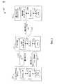
図2は、干渉および通信リソース管理を容易にするシステム例200のブロック図を示す。アクセス端末(AT)220はサービングアクセスポイント(AP)250と通信し、フォワードリンク(FL)265上でAT220にデータおよび制御コードのシンボルを送信し、リバースリンク(RL)235によってデータおよび制御を受信することができる。サービングAP250は、端末220へリソース割当てを送ることができる。そのようなリソース割当ては、AT220がAP250との通信を処理するため用いることができるように、電力レベル、および/またはパワースペクトル密度、パケットフォーマット、変調などのような通信リソースについての情報を伝える。リソース割当ては、RL235上のAT220から受信されたフィードバック情報に基づいた割当てを決定できるスケジューラ254によって管理することができる。スケジューラ254は、例えば、プロセッサ258およびメモリ262に接続できることに留意する。プロセッサ258は、スケジューラ254の一部またはすべての機能を容易に行うことができ、メモリ262は、例えば、スケジューリング割当てのレコードを保存することができる。ある態様において、スケジューラ254は、リソースレベルを調整し、Δ239に従ってリソースを再度割当てるために、通信リソースに関連してRL235上のオフセット(Δ239)値を受信することができる。そのような再度の割当ては他のセクタ上のAT220、AP280のような非サービングAPによって引き起こされた干渉を緩和するために用いることができる。AP250がΔ値を受信することに応じてAT220に対してより低い運用上の電力を再度割当てる場合、干渉を緩和することができる。ここでは、「Δ」「オフセット」および「デルタ」は互いに交換して使用することができ、それらの意味は、実質的に同じであることが意図されることに留意する。Δの決定/調整については以下で検討する。 FIG. 2 shows a block diagram of an
アクセス端末220はフォワードリンク295上の非サービスアクセスポイント280から情報を得ることができる。単一の非サービングAPがシステム例200に示されているが、AT220は複数の非サービングAPから情報を得ることができることに留意する。そのようなアクセスポイントは、サービングAP250が取得される時点で取得することができ、AT220に関してアクティブセットを形成することができる(該アクティブセットは、例えば、メモリ232に格納することができる。)。さらに、AT220は、そのようなアクティブセットを獲得した後に、熱雑音(IoT)上の干渉およびパイロットの受信電力に関連する、所定のしきい値に従ってリファインすることができる。非サービングAP280(あるいはリファインされたアクティブセットにおける別の非サービングAP)によって送信され/ブロードキャストされた情報は監視することができる。特に、AT220は、他セクタ干渉(OSI)の指標を監視することができる。アクティブなセットの外側のAPをも監視することができることに留意する(以下を参照)。あるセクタからの監視OSI指標かどうかに関するモバイルでの決定は、あらかじめ定められたしきい値と共に、該セクタのFLジオメトリー(例えば、獲得パイロットのフィルターされた信号対干渉および雑音比(SINR))に基づくことができる。
超過OSI299の指標は、フォワードリンク295の物理チャネル上に送信し、またはブロードキャストすることができる。ある態様において、第三世代ウルトラモバイルブロードバンド(3G UMB)システムでは、フォワードOSIチャネル(F−OSICH)はOSI指標を運ぶ。システム仕様に関わらず、そのようなチャネルの要件は、送信するセクタ(例えばセクタ104a−c)によりサーブされていないアクセス端末で該チャネルを復号する必要があることから、大きなカバレッジエリアになりえることを理解されたい。特に、OSI指標を運ぶチャネルは、獲得パイロットチャネル(例えば3G UMBにおけるフォワードチャネル品質指標パイロットチャネル(F−CQIPICH)、フォワード共通パイロットチャネル(F−CPICH))と同じカバレッジを持ち、隣接するセクタ(例えば第2および第3の最近傍)に大いに入り込む。さらに、OSI299指標を伴う物理チャネルは、パイロット擬似雑音符号系列以外にその送信するセクタに関する追加情報を必要とすることなく復号できることが必要である。そのような要件は、(i)要求される電力および時間周波数リソースの点から、(3G UMBにおけるF−OSICHのような)OSI指標を運ぶ物理制御チャネルを著しくコスト高にし、ならびに、(ii)OSI指標をチャネル上に送信(典型的にはスーパーフレーム毎にー回)できるレートを制限する(以下を参照)。F−OSICHのようなチャネルの大きなカバレッジによれば、3G UMBにおいて、アクセス端末により監視(例えば復号)されている獲得アクティブセットの外側のセクタによりOSI指標を送信できるようになる。 The indication of
非サービングアクセスポイント280はOSI生成コンポーネント284を含むことができ、プロセッサ288およびメモリ292につなぐことができる。コンポーネント284は、送信時刻間隔(例えばフレーム、つまりサブフレーム)に関して、長期間または短期間のOSI299指標を生成することができる。次に、かかる指標について説明する。
(i)低速OSI
長期間とは、1つまたは複数のスーパーフレームつまり無線通信フレームに相当する。ある態様では、3G UMBでは、スーパーフレームは、25個のフレームを包み込み、時間ガードおよび周期的な接頭部に依存しておよそ24−28ミリセカンドにわたる。別の態様において、第三世代ロングタームエボリューション(3G LTE)システムにおける無線通信フレームは、10ミリセカンドにわたる。そのような時間インターバルまたはより長い時間でコンポーネント284により生成されたOSI299指標のことを、ここでは「低速」OSIまたは通常OSIと称する。低速OSIは、調べられた時刻インターバル(例えばスーパーフレーム)に関する平均指標に相当し、チャネル干渉の変動が遅い時に非サービングAP(例えば250)によって観測された干渉を有効に反映することに留意する。さらに、低速OSIは、送信(例えば帯域幅(BW)割当て)のフィックスパタンを示すセクタに有効となり得、バッファステータスは、いくつかのスーパーフレームを伴う送信の間にあまり変わらない。当該システムで統計的に多重化が十分なされている場合、低速OSIは正確にセクタにおける干渉レベルを表わすことができ、例えばBWを増加させる端末は、BWが減少する無線装置を補償し、ネットワークは完全に充填(load)される。(I) Low speed OSI
Long term corresponds to one or more superframes, ie radio communication frames. In an aspect, in 3G UMB, a superframe wraps around 25 frames and spans approximately 24-28 milliseconds, depending on the time guard and periodic prefix. In another aspect, a wireless communication frame in a third generation long term evolution (3G LTE) system spans 10 milliseconds. The
(ii)高速OSI
通信システムが完全負荷状態でなく、バースト性ユーザが存在するようないくつかのシナリオにおいて、短期間のOSI299指標が必要となり得る。ある態様では、2つのセクタの境界の近くに位置する単一のアクセス端末が、著しく長い期間のサイレンス(silence)の後に急に新規の送信を開始し、隣接するセクタにおいて目下発生するリバースリンク送信に対するかなりの量の干渉を引き起こすといったシナリオがあり得る。低速OSI299指標を伴う物理的フォワードリンクチャネル(例えば3G UMBにおけるF−OSICH)を用いるのでは、隣接するセクタにとって、干渉を許容レベルまで減らすために、かかる端末に対し送信電力を低下させるのに数スーパーフレーム時間インターバルを必要とするかも知れないことを理解されたい。そのような長いインターバル中に、そのセクタにおいては、リバースリンク送信が厳しい干渉にさらされ、多数のパケット誤りが起こるかも知れない。ここでは、フレームまたはサブフレームごとの干渉の測定から生ずるOSI299指標のことを「高速」OSIと称する。(Ii) High-speed OSI
In some scenarios where the communication system is not fully loaded and there are bursty users, a short-
OSI生成コンポーネント284は、1つのサブキャリアごとに、または1つのサブバンドごとに(例えばサブキャリアのセット(図4))、低速および高速OSI指標の両者を生成することができることを理解されたい。そのようなシナリオでは、高速OSIは(時間周波数リソースで)十分に粒状になり、観測された干渉を端末AまたはBのどちらが引き起こしているのかを識別することができる。 It should be understood that the
バースト性端末(例えばアクセス端末220)の影響については、フォワードリンクおよびリバースリンクの長期的なチャネル品質はしばしば高度に相関するという事実を利用して対処/緩和することができる。リバースリンク上の非サービングセクタで強い干渉を引き起こす端末は、フォワードリンク(例えばフォワードリンク295)上の非サービングセクタからの強い信号(例えばパイロット信号)を恐らく観測することができ、アクティブセットにそのセクタを持つ。したがって、非サービングセクタ(例えばアクセスポイント280)の各アクセスポイントは低速OSI指標の送信に加え、フォワードリンク制御チャネルによりアクセス端末に対し低速OSI指標チャネルよりも低いオーバーヘッドの高速OSI指標を送信することができる。かかる送信を遂行するには、アクセス端末はそのアクティブセットに送信アクセスポイントを持つ必要がある。ある態様では、そのようなチャネルは、3G UMBシステムで送信できるフォワードリンク高速OSIチャネル(F−FOSICH)によって具体化することができる。高速OSI指標は、実質的に制限されたアクセス端末グループ(例えばそれらのアクティブセットにおいて送信しているAPを持つもの)に関して意図されることから、かかる情報を伝えるためのカバレッジ要件は、低速OSI指標を伴うチャネルの要件ほどは多くする必要がないことを理解されたい。別の態様において、以前に述べられたF−FOSICHは、すべてのFL物理層フレーム(その名前のルーツを明らかにする)中に存在し得ることから、非サービングアクセスポイント(例えば280)は、該アクセスポイントによってサービスされたセクタにおいて端末がパケット誤りを引き起こす前に、隣接するセクタにおけるバースト性アクセス端末(例えば220)からの干渉に、迅速に対処する/緩和することができる。 The effects of bursty terminals (eg, access terminal 220) can be addressed / mitigated by taking advantage of the fact that the long-term channel quality of the forward and reverse links is often highly correlated. A terminal that causes strong interference in a non-serving sector on the reverse link is likely to observe a strong signal (eg, pilot signal) from a non-serving sector on the forward link (eg, forward link 295), and that sector in the active set have. Thus, each access point in a non-serving sector (eg, access point 280) may transmit a fast OSI indicator with lower overhead than the slow OSI indicator channel to the access terminal over the forward link control channel in addition to sending the slow OSI indicator. it can. To perform such transmission, the access terminal needs to have a transmitting access point in its active set. In an aspect, such a channel may be embodied by a forward link fast OSI channel (F-FOSICH) that can be transmitted in a 3G UMB system. Since fast OSI indicators are intended for substantially restricted access terminal groups (eg, those with APs transmitting in their active set), the coverage requirement for conveying such information is the slow OSI indicator. It should be understood that there is no need for as many channel requirements as In another aspect, a non-serving access point (e.g., 280) may be included in a previously described F-FOSICH because it can be present in every FL physical layer frame (which reveals its root name). Interference from bursty access terminals (eg, 220) in adjacent sectors can be quickly addressed / mitigated before the terminals cause packet errors in sectors served by the access point.
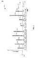
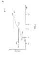
次に、OSI生成コンポーネント284の機能性をより詳しく説明する。該機能性の特徴を説明するために、K個の実例となるRL物理フレーム3101―310Kからなるサンプルスーパーフレームについての干渉メトリックの例図300である図3、および周波数領域における干渉メトリックの例図400である図4を参照する。かかるフレームは、AP250およびAP280ならびにAT220が動作する無線システムの仕様書によって規定された一定の時間にわたることに留意する。ある態様では、シンボルニューメロロジーはタイムスパンを決定する。一例として、3G UMBでは、諸フレームは、1つのフレームに種々の数の周期的な接頭部を含んでほぼ1ミリセカンドにわたり、スーパーフレームはK=25フレーム(またプリアンブル)を含んでいる。OSI指標を生成するために、非サービングアクセスポイント(例えば非サービングAP 280)は、それが異なる時間周波数リソース(例えばフレーム3101−310K)上で観察する干渉の量に基づいたメトリックを用いることができ、そのような測定された干渉の関数を利用することができる。さらに、しきい値(あるいは許容範囲)干渉メトリック値ITH320は超過干渉の指標を出すための参照として使用される。いくつかの要因はITHを決定することができ、これらの要因は典型的にはサービス・プロバイダーの目標ピークデータレート、目標スペクトル効率、目標レイテンシー、複雑性、および基地局/アクセスポイントのコストなどによって決定することができることを理解されたい。同様に、干渉は、例えばシステムにおける熱雑音および他のソースのシステマティックな雑音により決定できる参照値I(REF)350に関してdBで測ることができる。Next, the functionality of the
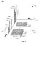
ある態様では、干渉レベルを決定する以下4種の手順/方法が考えられる。(1) 典型的なメトリックを低速OSIおよび高速OSIの両者の平均干渉としてもよい。すべての周波数リソース(例えばサブキャリア4101−410M(図4))および(最近の)幾つかのリバースリンクフレーム(例えば310J―310K、J<K)の平均により<I>(SLOW)330が導かれる。あるいは、最近のスーパーフレーム内のすべての周波数、フレームごとの平均を、ある定数(例えば25ミリセカンド、つまり3G UMBにおけるsupergrameのタイムスパン)の無限のインパルス応答(IIR)フィルタに渡すことにより、平均値を抽出することができる。図3には、各フレーム3101−310Kについて、干渉周波数平均3401−340Kが示される。平均干渉<I>(SLOW)330がしきい値ITH320以上である場合、超過OSIの指標はOSI生成コンポーネント284によって出される。上述したように、平均を計算することにより、無線通信セクタにおいてゆっくり変わる変動を捕らえることができる。ある態様では、3G UMBシステムにおいて、非サービングアクセスポイント(例えば280)は、すべての周波数リソースについて測定された平均干渉の長期的な平均(フィルターされたバージョン)に基づいたOSI指標を生成することにより、通常のOSIチャネル(F−OSICH)を用いて平均干渉を制御することができる。高速OSIに関して、(例えばすべてのまたはサブセットのサブキャリア4101−410M)サブキャリアあるいはサブバンドのような周波数リソースの全体を平均することは、高速平均干渉値3401―340Kをもたらすことができる。図4に示すように、高速OSIは、周波数領域において各サブキャリアごとに決定することができ、値4201−420Mは、特定のフレーム(図4はフレーム310Jを示す)内で観測された干渉メトリック値に対応する。各フレーム(例えばフレーム310J)については、高速OSIに対し周波数リソース全体の平均(例えば<I>(FAST)340J)に加え、干渉値4201―420Mを割当てることができることに留意する。In one embodiment, there are four possible procedures / methods for determining the interference level: (1) A typical metric may be the average interference of both low-speed OSI and high-speed OSI. <I>(SLOW) by the average of all frequency resources (eg subcarriers 4101 -410M (FIG. 4)) and (recent) several reverse link frames (eg 310J- 310K , J <
プロセッサ(例えばプロセッサ288)は該平均を計算することができ、ならびに手順(1)に関連する他の計算をすることができる。結果はメモリ(例えばメモリ292)に保存してもよい。さらに、プロセッサ(例えばプロセッサ288)は時間周波数領域において干渉レベルの測定を容易に行うことができる。データはメモリ(例えばメモリ292)に保存してもよい。 A processor (eg, processor 288) can calculate the average, as well as other calculations related to procedure (1). The result may be stored in a memory (eg, memory 292). Further, a processor (eg, processor 288) can easily measure the interference level in the time frequency domain. Data may be stored in a memory (eg, memory 292).
(2)干渉計測分布(例えば値3401−340Kは、フレーム3101−310Kの上の分布を表わす)の累積分布関数(CDF)の高百分位数(例えばテイル(末尾;tail))の監視から成る方法は、低速OSIおよび高速OSIの両者についてOSI生成コンポーネント284によって使用することができる。そのような方法により抽出された干渉レベルのことを、下記に述べる通り、ここではテイル干渉と称する。典型的に受信機からのリピート要求(例えばハイブリッド自動リピート要求(HARQ))を逃れることから送信中にセクタにおいて干渉レベルが急騰するとパケット破損および情報ロスの影響をより被りやすいテイル値を監視することは、最低限の性能を保証し、および/または制御チャネル上の通信を維持するのに良く適している。低速OSIに関して、OSI生成コンポーネント284は、スーパーフレーム(例えば340J―340K)内の最近のフレームに関してフレームごとの平均の分布および対応するCDFを生成し、特定の百分位数(例えば90%)に相当するテイル干渉値ITAIL(s)を抽出することができ、ITAIL(s)がITH320以上である場合にOSI指標を発行する。高速OSIについては、値ITAIL(F)がしきい値(例えばI(TH)320)以上である場合、OSI生成コンポーネント284はOSI指標を発行することができる。ここで、ITAIL(F)は、1セットの周波数リソース(例えば値4201−420M)に関して干渉レベルの分布のCDFの高い百分位数に関連した特定の干渉値に対応する。プロセッサ(例えばプロセッサ288)は該平均を計算することができ、ならびに当該手順に関連する他の計算を行うことができる。結果はメモリ(例えばメモリ292)に格納することができる。さらに、プロセッサ(例えばプロセッサ288)は時間周波数領域において干渉レベルの測定を容易に行うことができ、測定データはメモリ(例えばメモリ292)に保存することができる。(2) interference measurement distribution (for example, a value340 1 -340K, a frame310 1 -310 represents the distribution overK) high percentile of the cumulative distribution function (CDF) of (e.g. tail (tail; tail) ) Monitoring can be used by the
(3) または更に、OSI生成コンポーネント284が(1)と(2)に基づいたハイブリッドアプローチを用いることができ、低速OSIまたは高速OSIのいずれかについて、しきい値<I>TH付の平均干渉メトリック、およびしきい値I(TAIL)TH付のテイル干渉メトリックが同時に実装される。平均干渉レベルおよびテイル干渉レベルがそれぞれ<I>THおよびI(TAIL)THを越える場合、低速または高速OSIのどちらかに対応する超過OSI指標がOSI生成コンポーネント284によって発行される。これらのしきい値は、OSIコンポーネント生成284が生成しているOSI指標に依存して、低速OSIまたは高速OSIについて設定されることが理解されるべきである。プロセッサ(例えばプロセッサ288)は該平均を計算することができ、ならびに該手順に関連する他の計算をすることができる。データおよび結果はメモリ(例えばメモリ292)に保存してもよい。さらに、プロセッサ(例えばプロセッサ288)は時間周波数領域において干渉レベルの測定を容易に行なうことができ、データはメモリ(例えばメモリ292)に保存することができる。(3) Alternatively, the
(4)OSI生成コンポーネント284は実効干渉メトリックを決定し、超過OSIの指標を生成するためにそれをITHと対比することができる。システムダイバーシティを利用して実効メトリックを用いてもよく、例えば、メトリックが特定のリソース(例えばサブキャリアのセット)に対する大きな値を採用し、異なるリソース(例えばキャリアの別のセット)の同じメトリックの別の例は、小さな値を採用する場合、実効干渉メトリックの計算はそのようなダイバーシティを組込む。平均メトリックのような実効メトリックはそのようなダイバーシティ変動を平滑化することができるが、ダイバーシティプロフィール内の極端な値を向上させることができる他の実効メトリックがあることに留意する。別の実効メトリックは、システムキャパシティについての概念に基づいたものである。そのような場合では、1セットの時間周波数リソースに関して計算された干渉メトリックの種々の値は、キャパシティ値に変換することができる。計算されたキャパシティ値を平均し、該平均から実効干渉メトリックを抽出してもよい。該実効メトリックを計算する場合に、キャパシティ関数他の干渉レベルの関数を用いてもよい。そのような別の関数の一例は信号対干渉比である。(4) The
(1)と(2)に類似して、実効干渉メトリックの決定は、1セットの時間周波数リソース(例えば、フレーム3101−310K、サブキャリア4101−410M)上の干渉レベルの測定値に依存する。該測定値は、各時間周波数リソース(例えばシングルフレーム(シングルキャリア))上の測定、またはタイル(例えばフレーム時間スパン内の16のサブキャリア)のような時間周波数リソースのサブセットの平均条件を調べる測定に対応することが理解されるべきである。実効メトリックの生成には、干渉レベル(I)の関数(f)を用いる。上述したように、かかる関数はキャパシティまたは信号対干渉比としてもよい。関数fは複数個の測定された干渉レベルにおいて各干渉レベルについて評価され、その結果から平均(A)が生成される。平均を実効メトリック(上記参照)と見なす場合、関数fは恒等であること、例えばf(I)=Iに留意する。実効メトリック干渉は、引数値としてのAとともにf(I)の逆関数(例えばf−1(A))を評価することによって抽出される。測定値がすべて同一の場合、例えばINFが、異なる時間周波数リソースを調べても干渉レベルに変動がないシナリオに相当する場合、実効干渉メトリックは前記INFに一致することが理解されるべきである。Similar to (1) and (2), the determination of the effective interference metric is a measure of the interference level on a set of time-frequency resources (eg, frames 3101 -310K , subcarriers 4101 -410M ). Depends on. The measurement is a measurement on each time frequency resource (eg, single frame (single carrier)) or a measurement that examines the average condition of a subset of time frequency resources such as tiles (eg, 16 subcarriers within a frame time span). It should be understood that The function (f) of the interference level (I) is used for generating the effective metric. As described above, such a function may be a capacity or a signal to interference ratio. The function f is evaluated for each interference level at a plurality of measured interference levels, and an average (A) is generated from the results. Note that if we consider the average as the effective metric (see above), the function f is identical, eg f (I) = I. Effective metric interference is extracted by evaluating an inverse function of f (I) (eg, f−1 (A)) with A as an argument value. It should be understood that the effective interference metric matches the INF if the measurements are all the same, for example if the INF corresponds to a scenario where the interference level does not vary when examining different time frequency resources. is there.
プロセッサ(例えばプロセッサ288)は該平均を計算することができ、ならびに該手順に関連する、キャパシティの計算および実効値の導出のような他の計算をすることができる。データおよび結果はメモリ(例えばメモリ292)に保存してもよい。さらに、プロセッサ(例えばプロセッサ288)は時間周波数領域において干渉レベルの測定を容易に行なうことができる。データはメモリ(例えばメモリ292)に保存してもよい。 A processor (eg, processor 288) can calculate the average, as well as other calculations related to the procedure, such as capacity calculations and rms derivations. Data and results may be stored in a memory (eg, memory 292). Further, a processor (eg, processor 288) can easily measure the interference level in the time frequency domain. Data may be stored in a memory (eg, memory 292).
本件実効メトリックのアプローチを、干渉メトリックとして信号対雑音(SNR)比率を採用する場合について示す。例えば、複数のリソース(例えばサブキャリア、変調および符号化スキーム、アクセスポイントおよびアクセスノード…の送信および受信アンテナ)が通信に利用可能な場合、OSI生成コンポーネント284は、SNRの複数の値を計算することができる。したがって、実効SNRを定義し、かつ実効干渉メトリックを生成するのに複数のオプション(a)平均SNR、(b)平均干渉/雑音<I>と信号平均(〈S〉)の比、(c)キャパシティ(例えば単入力単出力(SISO)システムのためのシャノンのキャパシティ、多入力多出力システム(MIMO)におけるTelatarFoschiniキャパシティ)についてのある概念により計算した実効SNRが利用可能である。(c)のプログラムの実装は、各SNRの計算値を取得し、各値をキャパシティ単位に変換し、計算されたキャパシティの平均を求め、逆キャパシティ関数によって実効SNRを生成することからなる。OSI生成コンポーネント284は後のアクトを実行することができる。オプション(c)は、平均において通信リソースに敏感なSNRの値、前記リソースとは独立し、鈍感なSNR値を捕らえることにより、ダイバーシティの利点がある。代わりに、アクセスポイント(例えばAP280)が対応する信号値(S)値へのアクセスのない干渉(I)値を測定することができる場合、(例えば、リバースリンク上に受信されたか、メモリ292のようなストレージから読まれた)名目のSNOM値を設定することができる。また、異なるリソース上の干渉の測定によって、SNR値は定義することができ、実効SNR値を計算することができる。反対に、I値へのアクセスなしでS値にアクセスすることができる場合、名目のINOM値は決定することができる(例えば、リバースリンク上で受信され、またはメモリ292のようなストレージから読み出される)。そして実効SNR値は、Sを測定し、名目のI値を用いるSNR値を定義し、キャパシティに変形することにより生成される。OSI生成コンポーネント284は、実効SNR生成と関係する後のアクトを実行することができる。The present effective metric approach is shown for the case where a signal-to-noise (SNR) ratio is adopted as an interference metric. For example, if multiple resources (eg, subcarriers, modulation and coding schemes, access point and access node transmit and receive antennas) are available for communication,
実質的に、実効しきい値を計算するためにいかなるメトリックも用いることができることが認識されるべきである。干渉メトリックは、信号対干渉比、信号対干渉および雑音比のような他の性能メトリックに対応付けることができる。かかる性能メトリックは、さらに超過OSIの発行が保証されるかどうか決定するためにOSI生成コンポーネント284によって利用することができる干渉の値を導く。各々のアプローチ/手順(1)−(4)は特定概念に、より適しているかもしれないことが理解されるべきである。平均干渉メトリックの決定に依存するアプローチ(1)は、アクセス端末(例えばアクセス端末220)が、割当て詳細(例えば帯域幅(変調スキーム))の予備的知識または見込みのない総括的なリソース割当てを受信するシステムに適しているかもしれない。かかる場合では、上述したように、平均値は、割当てにおける可能な変動に対処し、したがって、適切な選択になりえる。測定された干渉レベルの分布のテイルを監視するアプローチ(2)および(3)は、制御チャネル通信の完全性を維持するのに適切になりえる。有効な干渉アプローチ(4)は、例えば、幾つかのサブキャリアがアクセス端末(例えばアクセス端末220)に割り付けられる大規模なリソース割当てに、より適しているかもしれない。かかるシナリオでは、移動局は、恐らく異なるリソースでチャネル条件のいくつかの達成を観測することができる、および、したがって、干渉レベルの有効な決定からの利益が得られる。 It should be appreciated that virtually any metric can be used to calculate the effective threshold. The interference metric can be associated with other performance metrics such as signal to interference ratio, signal to interference and noise ratio. Such performance metrics further lead to interference values that can be utilized by the
図2に関連して上述したように、アクセス端末220は、フォワードリンク295上で超過他セクタ干渉の指標を受信することができる。さらに、アクセス端末(例えば220)は、該端末によって獲得されたアクティブセット内の1セットの複数の非サービングアクセスポイント、またはそのような獲得アクティブセットの外側のAPから、(長距離または大きなカバレッジ、つまり3G UMB内のF−OSICHのようなFLチャネル(上記参照)によって)OSI指標を受信することができる。更に、図3および4に関連して検討したように、そのような指標は低速OSIまたは高速OSIのいずれかに対応することができる。次に、かかる異種の指標の相互作用、および干渉およびリソース管理とのそれらの関係について、説明の目的に適した図5を用いて検討する。図5Aおよび5Bは、それぞれ、オフセット値(Δs)およびOSI指標503に対するそれらの応答を表わすダイアグラム500および550である。 As described above in connection with FIG. 2, the
サービングアクセスポイント(例えばAP250)によってフォワードリンク(例えばFL265)上でアクセス端末(例えばAT220)にトラフィックチャネル送信のための初期のリソース割当てが伝えられると、割当てられたリソースの基準レベル(例えば図5Aおよび5B内のRREF506)は、端末で保存することができる。メモリ(例えばメモリ232)は記憶装置にそのような参照値を保存することができる。そのような基準レベルは、低速OSIおよび高速OSIに応答するオフセットΔに換算して調整してもよく、これにより端末のリソース割当てを管理することができる。該端末(例えばAT220)は、OSI指標503が端末自身の送信によって生成された干渉によって引き起こされた場合、それに応答することを決定することができ、また、端末は、アクセスポイント(例えばAP280)によってブロードキャストされるあらゆるOSI指標503(たとえ、かかる指標が端末によって用いられない時間周波数リソースに対応する場合であっても)に応答することを決定することができることが理解される。更に、かかる決定はOSI指標に対応する時間周波数リソースを同定することを含むことができる。オフセット調整はアクセスポイントで高いCQIのような有利なチャネル条件または利用可能なアンテナを利用するために用いることができる。したがって、端末はさらにOSI指標503に応じてオフセット値を調整するべきかどうか決定するためにCQIおよび他の利用可能リソースを用いることができる。Δ515はdBで測定することができる。ある態様において、Δ生成コンポーネント224は、オフセット値の大きさを決定する。管理された通信リソースが電力(すなわちパワースペクトル密度)である場合、アクセス端末によって非サービングセクタに与えられた干渉のレベルは緩和することができることに留意する。特に、アクセス端末(例えば端末220)は、基準レベル(例えばRREF506)へ適合するオフセット値Δ515を加えることにより、トラフィックチャネル(例えば3G UMB、逆のデータ・チャネル(R−DCH)内の)と関係するその送信電力またはパワースペクトル密度を計算することができる。Once the serving access point (eg, AP 250) communicates the initial resource assignment for traffic channel transmission to the access terminal (eg, AT 220) on the forward link (eg, FL 265), the reference level of the assigned resource (eg, FIG. 5A and RREF 506) in 5B can be saved at the terminal. A memory (eg, memory 232) can store such reference values in a storage device. Such a reference level may be adjusted in terms of the low-speed OSI and the offset Δ responsive to the high-speed OSI, thereby managing the resource allocation of the terminal. The terminal (eg, AT 220) may decide to respond if the
ある態様では、アクセス端末(例えばAT220)はただ1つのΔ値を保存してもよい。それは、低速(すなわち規則的)OSI指標512および高速OSI指標509の両方に基づいて調整される。図5Aは、そのようなシナリオを示し、オフセットΔ515はΔ’521を相殺するために値dΔ518によって増加される。または更に、アクセス端末(例えばAT220)は、1つの低速OSIΔ値(図5B内のΔS553で示される)を含む2つ以上のΔ値を保存することができ、通常OSI指標(例えば<I>(SLOW)512)に基づいて調整することができ、また1つまたは複数の高速OSIオフセット値(図5B内のΔF(1)−ΔF(P)で示される)を保持することができ、高速OSI指標(例えば<I>(FAST)509)に基づいて調整することができる。図5Bでは、遅く速い調整されたオフセット値はそれぞれΔ’S559およびΔ’F(1)−Δ’F(P)、5621−562Pで示される。その場合、複数のオフセット値はリソース割当てを調整するために用いられ、リソースの調整された値は<I>(SLOW)と<I>(FAST)に両方に基づいて決定されることに留意する。それらは、以上検討されたアプローチ(1)−(4)の少なくとも1つに従って決定される。端末が複数の高速OSIΔ値(例えば値5561−556Pおよび5621―562P)を維持する場合、各ΔF(J)は、異なるリバースリンクインターレース、フレーム、割当てなどに相当することが認識されるべきである。更に、高速OSIオフセット値のそのようなダイバーシティは、それらの時間インターバルにおいてその現在値でリソースレベル(例えば、インターレース)を容易に保存することができ、干渉メトリック上の有意な変更は検出されない。かかるダイバーシティは、1つのサブキャリア当たりのオフセット値の保存によりさらに拡張することができる(図4を参照)ことに留意する。In certain aspects, an access terminal (eg, AT 220) may store only one Δ value. It is adjusted based on both the slow (ie regular)
オフセット調整に適するアルゴリズムの説明に入る前に、通常のデルタに基づいたリソース管理(例えばパワー制御動作および干渉緩和)に高速OSIΔ調整(例えば値ΔF(1)−ΔF(P))が干渉するのを防ぐために、アクセス端末(例えばAT220)は、高速オフセット値の範囲を低速OSIΔ値(例えばΔS)以上に制限することに留意する。物理チャネル上の送信によって引き起こされた符号歪みが直交性の損失をもたらすとき、イントラセクタ干渉、リソース管理(例えばパワー制御アルゴリズム)は、受信信号のダイナミック・レンジについての要件を組込み、オフセットが採用することができる最小(ΔMIN、すなわち図5Aおよび5Bにおける524)および最大の(ΔMAX、すなわち図5Aおよび5Bにおける527)値を制限することができる。かかる最小および最大のオフセット値は、アクセス端末のサービングセクタ(例えば250)からブロードキャストされた干渉レベルについての情報に基づいて調整することができる。Before entering into the description of an algorithm suitable for offset adjustment, fast OSI Δ adjustment (eg value ΔF (1) −ΔF (P) ) interferes with normal delta based resource management (eg power control operation and interference mitigation). Note that to prevent this, the access terminal (eg, AT 220) limits the range of the fast offset value to be greater than or equal to the slow OSI Δ value (eg, ΔS ). Intra-sector interference, resource management (eg, power control algorithm) incorporates requirements for the dynamic range of received signals, and offsets are employed when code distortion caused by transmission on the physical channel results in loss of orthogonality The minimum (ΔMIN , ie, 524 in FIGS. 5A and 5B) and maximum (ΔMAX , ie, 527 in FIGS. 5A and 5B) values can be limited. Such minimum and maximum offset values may be adjusted based on information about interference levels broadcast from the serving sector (eg, 250) of the access terminal.
オフセット調整、例えば(オフセット値を増加させるか、減少させるか、維持する)調整を実行するべきかどうか決定すること、および/または調整(例えばdΔ518)の大きさに関して、アクセス端末(例えばAT220)は2つのアプローチを用いることができる。それは(i)確率的アプローチおよび(ii)決定論的なアプローチである。いずれかのアプローチを、アクセス端末において保存される各オフセット値(例えばΔS553(556P)およびΔF(1)−ΔF(P)5561)に用いることができる。ケース(i)において、(限定としてではなく)簡単のために、単一オフセットが保存される(図5A)とし、低速および高速OSI指標(例えば<I>(SLOW)512と<I>(FAST)509)を受信すると、アクセス端末は、Δ生成コンポーネント224によってオフセット値調整(例えば確率分布P=P(Δ、<I>(SLOW)、<I>(FAST)、rCQI)に基づいたdΔ518)の大きさおよび符号を決定することができる。ここで、rCQI=CQI(NSS)/CQI(SS)であり、例えば端末が該端末のサービングセクタ(SS)に比べて干渉を引き起こす他のセクタである非サービングセクタ(NNS)のチャネルの(チャネル品質指標(CQI)によって測定された)強度を示す。発行されたdΔ518の大きさおよび符号は、ΔMIN524およびΔMAX527によって課された境界内に調整されたオフセット、すなわちΔ’S559が存在するような状態である。代わりに、dΔ518の大きさは演繹的に指定することができる。また、確率分布Pは調整を実行するべきかどうか設定するために用いられる。かかる確率的アプローチ内では、超過OSI指標に対するアクセス端末の応答は、利用可能な通信リソースを維持すること(例えば減少ではない)でありえることが理解されるべきである。かかる特徴により、確率的アプローチ(i)は、完全にロードしたシステムに好適であり、低速OSI指標はquasiequilibrium値のまわりで変動する。OSI指標平均に対するいくつかの無線装置の確率的な応答を出力し、通信リソースの調整によって干渉の全面的な減少をもたらす。プロセッサ(例えばプロセッサ228)は確率分布を含むことができ、オフセット調整に見合う確率的な値を発行することができる。オフセットとOSI指標の値はレコード維持およびシステム動作の分析に関してメモリ(例えばメモリ232)において格納することができる。With respect to determining whether to perform an offset adjustment, eg, an adjustment (increasing, decreasing, or maintaining an offset value), and / or the magnitude of the adjustment (eg, dΔ518), the access terminal (eg, AT 220) may Two approaches can be used. It is (i) a probabilistic approach and (ii) a deterministic approach. Either approach can be used for each offset value stored at the access terminal (eg, ΔS 553 (556P ) and ΔF (1) −ΔF (P) 5561 ). In case (i), for simplicity (but not as a limitation), a single offset is stored (FIG. 5A), and slow and fast OSI indicators (eg, <I>(SLOW) 512 and <I>(FAST) ) ), The access terminal receives an offset value adjustment (eg, dΔ518 based on probability distributions P = P (Δ, <I>(SLOW) , <I>(FAST) , rCQI) by Δ generation component 224). Can be determined. Here, rCQI = CQI(NSS) / CQI(SS) , for example, the channel of the channel of the non-serving sector (NNS) which is another sector in which the terminal causes interference compared to the serving sector (SS) of the terminal Intensity (measured by quality index (CQI)). Magnitude and sign of the issued dΔ518 is a state as
決定論的なアプローチ(ii)の場合には、アクセス端末(例えば220)が、上方または下方のオフセット調整に関して特定の個別の(ステップ)値dΔ518の大きさをセットする重み関数w=w(<I>(SLOW)、<I>(FAST)、rCQI)によって決定されたアルゴリズムを利用することができる。アクセス端末においてプロセッサ(例えばプロセッサ228)によってかかる値を決定することができることが認識されるべきである。アプローチ(i)のように、オフセットとOSI指標の値は、レコード維持およびシステム動作の分析に関してメモリ(例えばメモリ232または262)において格納することができる。In the case of the deterministic approach (ii), the weighting function w = w (<, where the access terminal (eg 220) sets the magnitude of a particular individual (step) value dΔ518 with respect to the upper or lower offset adjustment. The algorithm determined by I>(SLOW) , <I>(FAST) , rCQI) can be used. It should be appreciated that such a value can be determined by a processor (eg, processor 228) at an access terminal. As with approach (i), the offset and OSI index values can be stored in memory (eg,
Δ生成コンポーネント224は低速OSIと高速OSIのオフセットを調整するのに決定論的なアプローチ(i)を用いることができるが、高速OSIオフセット調整については確率的アプローチ(ii)を回避してもよいことに留意する。ある態様において、高速OSI指標が受信される場合、隣接するセクタ内の干渉を減らすために決定論的に通信リソースを調整することが望ましいかもしれない。バースト的状況では、リソースレベルの確率的な調整が、バースト性アクセス端末によって与えられた干渉の増加につながることがある。超過OSI指標を受信するアクセス端末(例えばAT220)は、低速OSIおよび高速OSIΔ調整の両者に関して実質的にパラメータの同じセットを用い、実質的に同じアルゴリズムを利用することができる。または更に、アクセス端末は、異なるΔ値(ΔS553、ΔF(1)−ΔF(P)5561−556P)を調整するために異なるアルゴリズムおよび/またはパラメータの異なるセットを用いることができる。一例として、低速と高速で異なる必要があるデルタ調整のパラメータでは、ステップ幅(例えばdΔ518)が上下し、決定しきい値(例えばITH320)も異なる。The
別の態様において、Δ生成コンポーネント224は、高速OSIオフセットへの上界として低速OSIオフセットの値を用いることができる。それは超過OSIの指標を受信するアクセス端末(例えばAT220)において保存されたオフセットへの調整を生成するために用いられる。さらに別の態様において、アクセス端末は、オフセット値を調整するために高速OSI指標を用いることができる。しかし、上述したように、バースト性端末がシステム中に存在する場合に限り、高速OSIオフセット値が生成され、それまではアクセス端末には保持されないので、サービングアクセスポイント(例えばAP250)は、低速OSIΔ値の方へ高速OSIΔ値をドライブするためにアルゴリズムを実装することができる。バースト性送信が無い場合の長期間にわたる高速OSI値の保存は、ロングOSIオフセットの決定に不利に影響する場合があることに留意されたい。これを図6のダイアグラム600に示す。時刻τUに生成された高速OSIΔ値ΔF(U)610は、例えばサービングアクセスポイント250により、時刻τL1に生成された低速OSIオフセットΔS(L−1)620により与えられる上界値に向かってドライブされる(破線615)。時刻τLでは、新規の低速OSIオフセットΔS(L)625が例えばΔ生成コンポーネント224によって生成され、そしてΔF(U)は、新しく決定された低速オフセットに向かって再度ドライブされる(破線630)。新規のバースト的伝送がシステムで起こり、新規の高速OSIΔ値が生成されるまで、サービングアクセスポイントは高速オフセットΔF(U)610をドライブし続けることができる。In another aspect, the
ひとたびオフセット調整がΔ生成コンポーネント224によって実行されると、アクセス端末は、最新のオフセット(例えば図5A内のΔ’521および図5B内のΔ’S559,Δ’F(1)−Δ’F(P)5621−562P)の値を次のリソース割当てに対する示唆された値としてのそのサービングアクセスポイント(例えばAP250)に伝える。Once the offset adjustment has been performed by the
以上示され説明されたシステム例を考慮して、開示された主題に従って実装されてもよい方法は、図7および8のフローチャートに関して一層よく評価される。説明の簡単化のために、方法を一連のブロックとして示すが、クレームされた主題はブロックの数または順序で限定的ではなく、いくつかのブロックが、ここでは描かれ説明される他のブロックとは異なる順序で生じ、および/または同時に生じてもよいことが理解され、了解されるであろう。さらに、以下に説明された方法を実装するために、必ずしもすべての図示のブロックが必要とされるわけではない。ソフトウェア、ハードウェア、それらの組み合わせまたは任意の他の適合する手段(例えば装置、システム、プロセス、コンポーネント、…)によってブロックに関連した機能性が実装されてもよいことが認識される。また、以下、この明細書の全体にわたって開示された方法は、種々の装置にかかる方法を容易に運び転送するための製品上に格納されることができることが理解されるべきである。当業者は、一連の相互関係があった状態または状態遷移図においてのようにイベントとして二者択一で方法を表わすことができるかもしれないと理解し認識する。 In view of the example system shown and described above, methods that may be implemented in accordance with the disclosed subject matter will be better appreciated with respect to the flowcharts of FIGS. For ease of explanation, the method is shown as a series of blocks, but the claimed subject matter is not limited in number or order of blocks, and some blocks may be compared to other blocks depicted and described herein. It will be understood and understood that may occur in different orders and / or may occur simultaneously. Moreover, not all illustrated blocks may be required to implement the methods described below. It will be appreciated that the functionality associated with the blocks may be implemented by software, hardware, combinations thereof or any other suitable means (eg, apparatus, system, process, component,...). It should also be understood that the methods disclosed throughout this specification can be stored on products for easily carrying and transferring the methods for various devices. Those skilled in the art understand and appreciate that a method may be represented alternatively as an event, such as in a series of interrelated states or state transition diagrams.
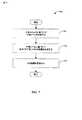
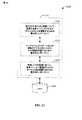
図7は、無線システムにおいてリソースおよび干渉を管理するのに必要となり得るOSI指標を生成するための方法の例700のフローチャートを示す。アクト710では、干渉レベルは干渉メトリックに基づいて決定される。選択されたメトリックは信号対干渉比のような性能メトリックになりえる。選択された干渉メトリックに基づいた干渉レベルの決定は、種々の時間周波数リソース上の干渉レベルの測定を含むことができる。ある態様では、高速短期の算定ならびに低速長期の決定を処理することができる。干渉レベルは、特定のフレーム(図3)およびインターレース、ならびに周波数領域(図4)におけるサブキャリアのような特定の時間領域リソースに関して決定することができる。かかる決定は高速算定に関係しているかもしれない。一例として、非サービングアクセスポイント280は、プロセッサ(例えばプロセッサ288)に連結されたOSI生成コンポーネント(例えばコンポーネント284)を用いて、かかる干渉レベル決定を処理することができる。プロセッサは、干渉レベルの測定、および平均およびシステムキャパシティベースの干渉レベルのような実効干渉メトリックを容易に計算することができる。アクト720では、OSI指標は、決定された干渉レベルに基づいて生成される。ある態様では、OSI指標の生成は、決定した有効干渉レベルを無線通信システムのサービス・プロバイダーによって設定することができるしきい値干渉レベル(図3および4)と比較することを含んでもよい。OSI指標はアクト730において送信される。態様では、非サービングアクセスポイント(例えばAP280)は専用のフォワードリンク(例えばFL 295)物理チャネル上でアクセス端末(例えばAT220)にOSI指標を伝える。かかるチャネルは高速OSI制御チャネルで具体化することができる。 FIG. 7 shows a flowchart of an
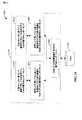
図8は、無線システムにおける、通信リソースを管理するための方法の例800のフローチャートを示す。アクト810では、他セクタ干渉(OSI)の指標が受信される。ある態様では、かかるOSI指標は、アクセス端末のアクティブセットにおける、ある非サービングアクセスポイントから受信する。OSI指標は、1つまたは複数のスーパーフレーム(図3)を含んで、長い期間に関して決定された指標に対応することができ、あるいはその指標はシングルフレーム(図3)に関して決定されて、短期の指標に対応することができる。820では、通信リソースに関連付けられたオフセット値がOSI指標に応じて調整されるべきかどうかが決定される。この決定は、干渉しきい値、チャネル品質指標またはセルトラヒック負荷に関して干渉超過の大きさに基づいてなされる。別の態様において、通信リソースは送信パワーまたはパワースペクトル密度(PSD)に対応することができる。または更に、通信リソースは、変調スキーム、帯域幅、サブキャリアの数、周期的な接頭部継続時間などに相当する。830では、通信リソースに関連したオフセットが調整される。通信リソースは電力またはPSDである場合、送信するアクセス端末(図2)のリバースリンク上の他セクタ干渉は、通信するにアクセス端末(例えばAT220)によって用いられた電力レベルを下げることにより緩和することができる。さらに別の態様では、Δvalueの調整は確率的または決定性アルゴリズムを用いて遂行してもよい。アクセス端末(例えばアクセス端末220)は、低速OSI指標および高速OSI指標に関連したオフセットを調整するために、実質的に同じであるアルゴリズムを用いることができる。 FIG. 8 shows a flowchart of an
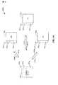
図9は、ここで述べられた1つまたは複数の態様に従って、無線通信環境におけるセル/セクタ通信を提供する多入力多出力(MIMO)システムにおける、送信機システム910(基地局140のような)および受信機システム950(例えばアクセス端末220)の実施形態のブロック図900である。送信機システム910では、幾つかのデータストリームのためのトラフィックデータはデータプロセッサ914を送信するために(TX)データ送信装置912から提供することができる。実施形態では、データストリームはそれぞれの送信アンテナ上に送信される。TXデータプロセッサ914は、符号化データを提供するためにそのデータストリームに選ばれた特定の符号化スキームに基づいて、各データストリームのトラフィックデータをフォーマットし、符号化し、およびインタリーブする。各データストリームの符号化データはOFDM技術を用い、パイロットデータに多重化されてもよい。パイロットデータは、典型的に既知のやり方で処理され、チャネル応答を推定するために受信機システムで用いることができる既知のデータパターンである。その後、各データストリームに関して多重パイロットおよび符号化データは、変調シンボルを提供するためにそのデータストリームに選ばれた、特定の変調スキーム(例えば二進移相変調(BPSK)、4位相偏移変調(QPSK)、複数の位相偏移キーイング(M−PSK)またはm−順序直交振幅変調(M−QAM))に基づいて、変調される(例えばマッピングされたシンボル)。各データストリームに関して、データレート、符号化および変調は、プロセッサ930によって実行された命令によって決定されてもよく、該データならびに命令はメモリ932において格納されてもよい。更に、このイノベーションのある態様に従って、送信機は、超過OSIの指標に応じて計算されたデルタ値に依存する変調スキームを切り替えることができる。 FIG. 9 illustrates a transmitter system 910 (such as base station 140) in a multiple-input multiple-output (MIMO) system that provides cell / sector communication in a wireless communication environment in accordance with one or more aspects described herein. And a block diagram 900 of an embodiment of a receiver system 950 (eg, access terminal 220). At
その後、すべてのデータストリームに関して変調シンボルはTX MIMOプロセッサ920に提供される。それはさらに変調シンボル(例えばOFDM)を処理してもよい。その後、TX MIMOプロセッサ920は922TによってNTトランシーバー(TMTR/RCVR)922AにNT変調シンボルストリームを供給する。ある実施形態では、TX MIMOプロセッサ920は、データストリームのシンボル、およびシンボルが送信されているアンテナにビームフォーミング重量(あるいは前符号化)を適用する。トランシーバー922はそれぞれ、1つまたは複数のアナログ信号を提供するためにそれぞれのシンボルストリームを受信し処理し、さらに、アナログ信号を整えて(例えば、増幅し、フィルターし、アップコンバーターで変換する)、MIMOチャネル上の送信に適している変調された信号を提供する。その後、トランシーバー922Aから922TまでのNT個の変調された信号は、NTアンテナ9241から924Tによってそれぞれ送信される。受信機システム950では、送信された変調信号は、952RからNRアンテナ9521によって受信される。また、各アンテナ952からの受信信号は954Rによってそれぞれのトランシーバー(RCVR/TMTR)954Aに提供される。各トランシーバー9541−954Rはそれぞれの受信信号を整え(例えば、フィルターし、増幅し、ダウンコンバートする)、ディジタル化してサンプルを提供し、さらに該サンプルを処理して「受信した」シンボルストリームを提供する。The modulation symbols are then provided to
その後、RXデータプロセッサ960は、特定の受信機処理技術に基づいたNRトランシーバー9541−954RからNR受信シンボルストリームを受信し処理してNT「検出された」シンボルストリームを供給する。その後、RXデータプロセッサ960は、データストリームのためのトラフィックデータを回復するために各検出されたシンボルストリームを復調し、デインターリーブし、復号する。RXデータプロセッサ960による処理は、送信機システム910のTX MIMOプロセッサ920およびTXデータプロセッサ914によって実行されたものと相補的である。プロセッサ970は、どの前符号化行列を用いるか周期的に決める、かかる行列はメモリ972において格納することができる。プロセッサ970は、行列インデックス部分およびランク値部分を含むリバースリンクメッセージを作成する。メモリ972は、プロセッサ970によって実行されることでリバースリンクメッセージを作成する命令を格納してもよい。リバースリンクメッセージは、通信リンクまたは受信データストリームに関する種々の型の情報、またはそれらの組み合わせを含んでもよい。一例として、かかる情報はデータパケットフォーマットの復号に関して調整された通信リソース、スケジューリングされたリソースを調整するためのオフセットおよび情報を含むことができる。その後、リバースリンクメッセージは、データ送信装置936からの多数のデータストリームについてのトラフィックデータを受信するTXデータプロセッサ938によって処理され、変調器980によって変調され、トランシーバー954Rから954Aにより整えられ、送信機システム910に送り戻される。Then,
送信機システム910では、受信機システム950からの変調された信号は、アンテナ9241−924Tによって受信され、トランシーバー922A−922Tによって整えられ、復調器940によって復調され、受信機システム950によって送信されたリザーブ(reserve)リンクメッセージを抽出するためにRXデータプロセッサ942によって処理される。その後、プロセッサ930は、ビームフォーミングウェイトの決定に関してどの前符号化行列を用いるかを決定し、該抽出されたメッセージを処理する。At
上述した工程に従い図9に示されるように、シングルユーザーMIMOモードは、単一の受信機システム950が送信機システム910と通信する場合に対応する。かかるシステムでは、NT送信機9241−924T(さらにTXアンテナとして知られている)およびNR受信機9521−952R(さらにRXアンテナとして知られている)は、無線通信の行列チャネル(例えばレーリーチャネル、またはガウスのチャネル)を構成する。SU−MIMOチャネルは任意の複素数のNR×NT行列によって説明される。チャネルのランクは、NR×NTチャネルの代数ランクと等しい。地空または空間周波数符号化において、ランクは、チャネルに関して送られるデータストリーム(すなわちレイヤ)の数と等しい。ランクは、高々、min{NT、NR}に等しいことが理解されるべきである。NT送信およびNR受信アンテナによって構成されたMIMOチャネルは、NV独立チャネルへ分解されてもよい。それを空間チャネルと称する。ここで、NV≦min{NT(NR}である。NV独立チャネルの各々は1次元に対応する。As shown in FIG. 9 according to the steps described above, the single user MIMO mode corresponds to the case where a
ある態様ではトーンωのOFDMにより送信または受信されたシンボルは、次式によりモデル化することができる。
(1)ここで、y(ω)は受信データストリームでありNR×1ベクトルである。H(ω)は、トーンω(例えば時間依存のチャネル応答行列hのフーリエ変換)のチャネル応答NR×NT行列である。c(ω)はNT×1出力シンボルベクトルである。また、n(ω)はNR×1雑音ベクトル(例えば付加的な白色ガウス雑音)である。前符号化はNV×1レイヤベクトルをNT×1前符号化出力ベクトルに変換することができる。NVは、送信機910によって送信されたデータストリーム(レイヤ)の実数であり、NVは、チャネルコンディション、および端末によって報告されたランクの少なくとも一部に基づいて、送信機(例えばアクセスポイント250)の自由裁量でスケジューリングすることができる。c(ω)が少なくとも1つの多重化スキームの結果、および送信機によって適用された少なくとも1つの前符号化(あるいはビームフォーミング)スキームであることが認識されるべきである。さらに、c(ω)は電力利得行列に畳み込まれる。それは、送信機910の量が送信に各データストリームNVを割り付ける電力を決める。かかる電力利得行列がアクセス端末220に割当てられるリソースになりえることは認識されるべきである。また、それは、オフセットの調整を通じてここで説明したように管理することができる。無線チャネルのFL/RL相互性を考慮して、MIMO受信機950からの送信についても、実質的に同じである構成要素を含む等式(1)にならってモデル化することができることが理解されるべきである。更に、受信機950は、さらにリバースリンク内のデータを送信する前に前符号化スキームを適用することができる。(1) where y (ω) is the received data stream and is an NR × 1 vector. H (ω) is the channel response NR × NT matrix of the tone ω (eg, the Fourier transform of the time-dependent channel response matrix h). c (ω) is an NT × 1 output symbol vector. N (ω) is an NR × 1 noise vector (for example, additional white Gaussian noise). Precoding can convert an NV × 1 layer vector to an NT × 1 precoded output vector. NV is the real number of data streams (layers) transmitted by the
システム900(図9)において、NT=NR=1であるとき、システムは、ここで述べられた1つまたは複数の態様に従って、無線通信環境におけるセクタ通信を提供し得る単入力単出力(SISO)システムに変わる。In system 900 (FIG. 9), when NT = NR = 1, the system may provide single-input single-output (in accordance with one or more aspects described herein) for providing sector communication in a wireless communication environment. SISO) system.
図10は、3つのAT220P、220Uおよび220Sがアクセスポイント250と通信する例示のマルチユーザMIMOシステム1000を示す。アクセスポイントはNTTXアンテナ9241−924Tを持つ。また、ATの各々には複数のRXアンテナがある。すなわち、ATPはNPアンテナ9521−952Pを持ち、APUはNUアンテナ9521−952Uを持ち、APSはNSアンテナ9521−952Sを持つ。端末とアクセスポイントの間の通信はアップリンク1015P、1015Uおよび1015Sによって達成される。同様に、ダウンリンク1010P、1010Uおよび1010Sでは、アクセスポイント250と端末ATP、ATU、およびATSの間で容易に通信が行える。さらに、各端末と基地局の間の通信は、図9およびその対応する詳細な説明において示されたとおり、実質的に同じ方法で、実質的に同じコンポーネントにより実行される。端末がアクセスポイント250によってサービスされたセル内の実質的に異なる位置において位置することができるので、ユーザ機器220P、220Uおよび220Sはそれぞれそれ自身のランクと共に、それ自身の行列チャネルhαおよび応答行列Hα(α=P、UおよびS)を持っている。基地局250によってサービスされたセルの中にある複数個のユーザーに起因してイントラセル干渉を示すことがある。図10では3つの端末で示したが、MU−MIMOシステムは、いかなる数の端末(下にインデックスkで示す)を含むことができることが理解されるべきである。アクセス端末220P、220Uおよび220Sの各々は超過他セクタ干渉の指標に応答することができ、各々は、AT250に対し、1つまたは複数の調整された通信リソース、スケジューリングされたリソースを調整するためのオフセット、ならびにOSI指標を考慮して送信に関して用いられた適合データパケットフォーマットを復号するための情報を伝えることができる。上述したように、AT250は、端末220P、220Uおよび220Sの各々について、互いのリソース割当てに従って、およびそれとは無関係に、リソースを再スケジューリングすることができる。FIG. 10 shows an exemplary
ある態様ではユーザk、トーンωのOFDMにより送信または受信されたシンボルは、次式によりモデル化することができる。
ここで、シンボルは等式(1)の場合と同じ意味を持つ。マルチユーザーダイバーシティにより、ユーザーkによって受信された信号における他のユーザーの干渉が、等式(2)の左辺内の第2の項でモデル化されることが認識されるべきである。プライム符号(’)は、送信されたシンボルベクタckが合計から除外されることを示す。一連の項は、セルにおいて他のユーザーに送信機(例えばアクセスポイント250)によって送信されたシンボルのユーザーk(そのチャネル応答Hkによる)による受信を表わす。Here, the symbols have the same meaning as in equation (1). It should be appreciated that due to multi-user diversity, the interference of other users in the signal received by user k is modeled by the second term in the left hand side of equation (2). The prime code (') indicates that the transmitted symbol vectorkk is excluded from the total. The series of terms represents the reception by user k (according to its channel response Hk ) of symbols transmitted by the transmitter (eg, access point 250) to other users in the cell.
図11は、ここで説明された種々の態様に従い、無線通信システムにおけるリバースリンク通信リソースおよび干渉レベルの管理を統合するシステム1100のブロック図である。ある例では、システム1100はアクセス端末1102を含んでいる。図示のように、アクセス端末1102は1つまたは複数のアクセスポイント1104から信号を受信し、アンテナ1108によって1つまたは複数のアクセスポイント1104へ送信することができる。さらに、アクセス端末1102は、受信機1110または実質的に他の電気機器を含み、アンテナ1108から情報を得る。ある例では、受信機1110は、受信された情報を復調する復調器(Demod)1112に動作可能なように接続されてもよい。復調されたシンボルは、プロセッサ1114によって分析することができる。プロセッサ1114は、データおよび/またはアクセス端末1102に関係するプログラムコードを格納できるメモリ1116に接続することができる。さらに、アクセス端末1102は、方法700、800および/または他の適合する方法を実行するためにプロセッサ1114を用いることができ、または、実質的に他の電気機器を用いることができる。アクセス端末1102は、さらに1つまたは複数のアクセスポイント1104へのアンテナ1108によって送信機1120による送信に関して信号を多重化することができる変調器1118を含むことができる。 FIG. 11 is a block diagram of a
図12は、ここに説明された種々の態様に従って無線通信システムにおけるリバースリンク通信リソースおよび干渉管理を統合するシステム1200のブロック図である。ある例では、システム1200は基地局またはアクセスポイント1202を含んでいる。図示のように、アクセスポイント1202は受信(Rx)アンテナ1206によって1つまたは複数のアクセス端末1204から信号を受信し、送信(Tx)アンテナ1208によって1つまたは複数のアクセス端末1204に送信することができる。 FIG. 12 is a block diagram of a
さらに、アクセスポイント1202は、受信アンテナ1206から情報を得る受信機1210を含むことができる。ある例では、受信機1210は動作可能なように復調器(Demod)1212または実質的に他の電気機器に関連づけられ、受信された情報を復調する。その後、復調されたシンボルは、プロセッサ1214によって分析することができる。プロセッサ1214は、メモリ1216に接続され、符号クラスタ、アクセス端末割当て、関連するルックアップテーブル、ユニークなスクランブリングシーケンスおよび/または他の適合する型の情報と関係する情報を格納することができる。アクセスポイント1202は、さらに1つまたは複数のアクセス端末1204への送信アンテナ1208によって送信機1220による送信に関して信号を多重化することができる変調器1218を含んでもよい。 Further,
次に、開示された主題の態様を実施可能にすることができるシステムを図13および14に関連して説明する。かかるシステムは機能ブロックを含むことができ、プロセッサまたは電子機械、ソフトウェア、またはそれらの組み合わせ(例えばファームウェア)によって実装された機能を表わす機能ブロックを含むことができる。 A system that can enable aspects of the disclosed subject matter is now described with respect to FIGS. Such a system can include functional blocks, and can include functional blocks that represent functions implemented by a processor or electronic machine, software, or a combination thereof (eg, firmware).
図13は、本件開示のある態様に従って無線通信システムにおけるリソース管理を可能にするシステム例1300のブロック図を示す。システム1300は、無線端末(例えばアクセス端末220)内に、少なくとも部分的に存在することができる。システム1300は、連動する電子コンポーネントの論理グルーピング1310を含んでいる。ある態様では、論理グルーピング1310は、他セクタ干渉指標の監視のために非サービングアクセスポイント(AP)セットを設立するための電子コンポーネント1315、該監視セット内の1つまたは複数のAPからOSI指標を受信するための電子コンポーネント1325、また該受信したOSI指標に従って通信リソースに関連付けられたオフセット値を調整するための電子コンポーネント1335を含んでいる。 FIG. 13 shows a block diagram of an
システム1300は、電気部品1315および1325に関連付けられた機能を実行するための命令ならびに、かかる機能の実行中に生成され得る測定データおよび計算データを保存するメモリ1340を含んでもよい。メモリ1340の外側にあるものとして示したが、一つまたは複数の電子コンポーネント1315、1325および1335がメモリ1340内に存在してもよいことを了解されたい。
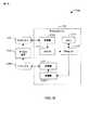
図14は、決定した干渉レベルに従って超過他セクタ干渉の指標を生成および発行することによって無線通信システムにおける干渉管理を可能にするシステム例のブロック図である。システム1400は、基地局(例えばアクセスポイント280)内に、少なくとも部分的に存在することができる。システム1400は、連動する電子コンポーネントの論理グルーピング1410を含んでいる。ある態様では、論理グルーピング1410は干渉メトリックに基づいた高速干渉レベル、および実効干渉メトリックに基づいた低速干渉レベルをそれぞれ決定するための電子コンポーネント1415および1425を含んでいる。更に、論理グルーピング1410は、高速干渉レベルに従って高速他セクタ干渉(OSI)の指標を生成するためのコンポーネント1435、および低速干渉レベルに従って低速他セクタ干渉の指標を生成するためのコンポーネント1445を含んでいる。生成したOSI指標を送信するための電子コンポーネント1455を論理グルーピング1410内に含んでもよい。 FIG. 14 is a block diagram of an example system that enables interference management in a wireless communication system by generating and issuing an indicator of excess other sector interference according to a determined interference level.
さらに、システム例1400は、さらに電子的コンポーネント1415、1425、1435、1445および1455に関連関連付けられた機能を実行するための命令、ならびに、かかる機能の実行中に生成され得る測定データおよび計算データを保存するメモリ1460を含むことができる。メモリ1460の外側にあるものとして示したが、一つまたは複数の電子コンポーネント1415、1425、1435、1445および1455がメモリ1460内に存在してもよいことを了解されたい。 Further, the
ここに説明された実施形態は、ハードウェア、ソフトウェア、ファームウェア、ミドルウェア、マイクロコードまたは任意のそれらの組み合わせによって実装することが理解される。システムおよび/または方法がソフトウェア、ファームウェア、ミドルウェアまたはマイクロコード(プログラムコードまたは命令セグメント)で実装される場合、それらはストレージコンポーネントのような機械可読媒体に格納することができる。命令セグメントはプロシージャ、関数、サブプログラム、プログラム、ルーチン、サブルーチン、モジュール、ソフトウェアパッケージ、クラス、または命令とデータ構造とプログラム文の任意の組合せを表わすことができる。命令セグメントは、情報、すなわちデータ、引数、パラメータ、あるいはメモリコンテンツを渡し、および/または受け取ることにより、別の命令セグメントまたはハードウェア回路に連結することができる。情報、引数、パラメータ、データ等は、メモリ共有、メッセージパッシング、トークンパッシング、ネットワーク送信などを含む何らかの適切な手段を用いて渡し、フォワードし、または送信してもよい。 It is understood that the embodiments described herein are implemented by hardware, software, firmware, middleware, microcode, or any combination thereof. If the systems and / or methods are implemented in software, firmware, middleware or microcode (program code or instruction segments), they can be stored in a machine-readable medium such as a storage component. An instruction segment can represent a procedure, function, subprogram, program, routine, subroutine, module, software package, class, or any combination of instructions, data structures, and program statements. An instruction segment can be coupled to another instruction segment or a hardware circuit by passing and / or receiving information, ie, data, arguments, parameters, or memory contents. Information, arguments, parameters, data, etc. may be passed, forwarded, or transmitted using any suitable means including memory sharing, message passing, token passing, network transmission, etc.
ソフトウェア実装については、ここに説明された技術は、ここに説明された機能を実行するモジュール(例えばプロシージャ、関数など)に実装することができる。ソフトウェアコードは記憶装置に格納し、プロセッサによって実行することができる。記憶装置はプロセッサ内に実装してもよいし、プロセッサ外部のものとしてもよい。その場合には、当該技術分野において知られる種々の手段によりプロセッサに対して通信可能に結合してもよい。 For software implementation, the techniques described herein may be implemented in modules (eg, procedures, functions, etc.) that perform the functions described herein. The software code can be stored in a storage device and executed by a processor. The storage device may be mounted in the processor or may be external to the processor. In that case, it may be communicatively coupled to the processor by various means known in the art.
ここで用いられる語「プロセッサ」は、古典的アーキテクチャのコンピュータまたは量子コンピュータのことをいう。古典的アーキテクチャは、シングルコアプロセッサ、ソフトウェアマルチスレッド実行能力を備えたシングルプロセッサ、マルチコアプロセッサ、ソフトウェアマルチスレッド実行能力を備えたマルチコアプロセッサ、ハードウェアマルチスレッド技術を備えたマルチコアプロセッサ、並列プラットフォーム、および分散共有メモリを備えた並列プラットフォームを含むが、これらには限定されない。さらに、プロセッサが、集積回路、特定用途向け集積回路(ASIC)、プログラマブルロジックコントローラ(PLC)、コンプレックスプログラマブルロジックデバイス(CPLD)、またはフィールドプログラマブルゲートアレイ(FPGA)のことを指してもよい。量子コンピュータアーキテクチャは、ゲートまたは自己組織クワンタムドット中に具現されたキュービット、核磁気共鳴プラットフォーム、超伝導ジョセフソン接合などに基づくものとしてよい。空間利用を最適化し、ユーザ機器の性能を向上させるために、プロセッサが分子およびクワンタムドットに基づくトランジスタ、スイッチ、ゲートのようなナノスケールアーキテクチャを利用してもよい。 As used herein, the term “processor” refers to a classical architecture computer or quantum computer. Classical architecture includes single-core processors, single processors with software multi-thread execution capability, multi-core processors, multi-core processors with software multi-thread execution capability, multi-core processors with hardware multi-thread technology, parallel platforms, and distributed Including but not limited to parallel platforms with shared memory. Further, a processor may refer to an integrated circuit, an application specific integrated circuit (ASIC), a programmable logic controller (PLC), a complex programmable logic device (CPLD), or a field programmable gate array (FPGA). The quantum computer architecture may be based on a qubit embodied in a gate or self-organized quantum dot, a nuclear magnetic resonance platform, a superconducting Josephson junction, or the like. To optimize space utilization and improve user equipment performance, the processor may utilize nanoscale architectures such as transistors, switches, and gates based on molecules and quantum dots.
更に、本件明細書では、用語「メモリ」は、データ蓄積、アルゴリズム蓄積、および画像蓄積、デジタル音楽および映像の蓄積、チャートおよびデータベースのような情報蓄積のことを指すが、これらには限定されない。ここに説明されたメモリコンポーネントは、揮発性メモリまたは不揮発性メモリのいずれかであってもよく、揮発性メモリおよび不揮発性メモリの両者を含んでもよいことが理解されるであろう。限定ではなく実例として、不揮発性メモリは、読み取り専用メモリ(ROM)、プログラマブルROM(PROM)、EPROM(EPROM)、EEROM(EEPROM)またはフラッシュメモリを含んでもよい。揮発性メモリはランダムアクセスメモリ(RAM)を含み、外部キャッシュメモリとして働く。限定ではなく実例として、RAMは、シンクロナスRAM(SRAM)、ダイナミックRAM(DRAM)、シンクロナスDRAM(SDRAM)、ダブルデータレートSDRAM(DDR SDRAM)、エンハンストSDRAM(ESDRAM)、Synchlink DRAM(SLDRAM)およびダイレクトRambusRAM(DRRAM)のような様々な形式が利用可能である。さらに本開示のシステムのメモリコンポーネントおよび/または方法は、これらおよび他の任意の適合する型のメモリを含むことが意図されるが、これらには限定されない。 Further, as used herein, the term “memory” refers to, but is not limited to, data storage, algorithm storage, and image storage, digital music and video storage, charts and databases. It will be appreciated that the memory components described herein may be either volatile memory or non-volatile memory, and may include both volatile and non-volatile memory. By way of example, and not limitation, non-volatile memory may include read only memory (ROM), programmable ROM (PROM), EPROM (EPROM), EEROM (EEPROM), or flash memory. Volatile memory includes random access memory (RAM) and acts as external cache memory. By way of example and not limitation, RAM can be synchronous RAM (SRAM), dynamic RAM (DRAM), synchronous DRAM (SDRAM), double data rate SDRAM (DDR SDRAM), enhanced SDRAM (ESDRAM), Synclink DRAM (SLDRAM) and Various formats such as direct Rambus RAM (DRRAM) are available. Further, the memory components and / or methods of the system of the present disclosure are intended to include, but are not limited to, these and any other suitable type of memory.
さらに、この開示において用いられるように、用語「電気機器」は、特定の目的を果たす電子通信の実体のことをいい、そのような目的の例は、(以下に限定されないが)デジタル信号の送受信、無線周波数電磁放射の送受信、デジタル信号の処理(例えば多重化/デマルチプレクシング、変調、デジタルビットを分割/連結すること)、当該電気機器の一部分の、または該電気機器の外部となり得る上述したプロセッサによりロジックを実行すること、当該電気機器の一部分の、または該電気機器の外部となり得る上述したメモリに情報を記憶すること、ネットワークにおいてまたはスタンドアロンでコンピュータと通信すること、電気機器に特定のアクトを実行させるコードの実行などを含む。 Further, as used in this disclosure, the term “electrical equipment” refers to an entity of electronic communication that serves a specific purpose, examples of such purposes include (but are not limited to) transmission and reception of digital signals. Radio frequency electromagnetic radiation transmission / reception, digital signal processing (eg, multiplexing / demultiplexing, modulation, splitting / concatenating digital bits), part of the electrical equipment, or external to the electrical equipment as described above Executing logic by a processor, storing information in the above-mentioned memory, which may be part of or external to the electrical device, communicating with a computer in a network or stand-alone, act specific to the electrical device Execution of code that executes
以上説明した事項は、1つまたは複数の態様の例を含んでいる。当然ながら、前述の態様を説明する目的のために、コンポーネントまたはメソドロジの考えられる組合せをすべて説明することはできない。しかし、当業者であれば、多くのさらなる組合せおよび種々の態様の置換が可能であることを認識することができる。従って、説明された態様は、添付の特許請求の精神および範囲に含まれる変更、修正および変形のすべてを包含することが意図される。さらに、用語「含む(include)」が詳細な説明またはクレームのいずれかで用いられる限りにおいて、この用語は、クレームで遷移語として使用され、「具備する(comprising)」が解釈される場合の用語「具備する」と同様に、包括的であることが意図されている。
以下に、本願出願の当初の特許請求の範囲に記載された発明を付記する。
[1] 他セクタ干渉(OSI)の指標を受信すること;
通信リソースに関連付けられたデルタ値が前記受信したOSI指標に応じて調整されるべきかどうか決定すること、該決定は前記OSI指標に対応する時間周波数リソースを同定することを含む;および
前記通信リソースに関連付けられた前記デルタ値を調整することを含む無線システムにおけるリソース管理の方法。
[2] 前記デルタ値の前記調整は、前記受信したOSI指標、現在のデルタ値、およびチャネル強度メトリックに依存する確率分布に基づいて、前記デルタ値を増加させるべきか、減少させるべきか、維持するべきかどうかをランダムに決定することを含む上記[1]の方法。
[3] 前記デルタ値の前記調整は、決定性アルゴリズムを採用することを含み、前記受信したOSI指標、現在のデルタ値、およびチャネル強度メトリックに依存する重み関数が、特定の離散値に従ってデルタ値を増加させるか減少させる上記[1]の方法。
[4] 調整されたデルタ値を保持することをさらに含む上記[1]の方法。
[5] 調整されたデルタ値のための境界として役立つ1つまたは複数のデルタ値を計算することをさらに含む上記[1]の方法。
[6] フォワードリンクのスーパーフレームごとに、前記OSI指標を受信する上記[1]の方法。
[7] インターレースの復号で前記OSI指標を受信する上記[1]の方法。
[8] フォワードリンクのフレームごとに、前記OSI指標を受信する上記[1]の方法。
[9] OSI指標の受信は、1セットのサブフレーム、1セットのフレーム、および1セットのサブキャリアからなるグループから選択された1セットにわたって平均した干渉メトリックの値を受信することを含む上記[1]の方法。
[10] アクセスポイントのセットを取得し、取得したアクセスポイントのセット内のアクセスポイントから超過他セクタ干渉(OSI)の指標を受信し、前記超過OSI指標に従って通信リソースに関連付けられたオフセット値を調整し、前記調整したオフセット値保持するように構成された集積回路;および
データを格納するための前記集積回路に結合されたメモリを具備する無線通信装置。
[11] 前記集積回路は、サービングアクセスポイントからリソース割当てを受信するようにさらに構成された上記[10]の無線通信装置。
[12] 前記集積回路は、サービングアクセスポイントに前記調整したオフセット値を送信するようにさらに構成された上記[11]の無線通信装置。
[13] 前記集積回路は、前記オフセット値を調整するために確率的アルゴリズムを用いるようさらに構成された上記[10]の無線通信装置。
[14] 前記集積回路は、前記オフセット値を調整するために決定性アルゴリズムを用い、前記メモリから前記アルゴリズムを定義する1セットのパラメータを引き出すようにさらに構成された上記[10]の無線通信装置。
[15] 前記格納されたデータは、有効な干渉、平均干渉、干渉レベルの分布の特定百分位数に対応する干渉、あるいは任意のそれらの組み合わせの計算された値を含む上記[10]の無線通信装置。
[16] 非サービングアクセスポイント(AP)のセットを設定して他セクタ干渉指標を監視するための手段;
前記監視セット内の1つまたは複数のAPから他セクタ干渉(OSI)指標を受信するための手段;および
前記受信したOSI指標に従って通信リソースに関連付けられたオフセット値を調整するための手段を具備する無線通信システムにおけるリソース管理を容易にする装置。
[17] 前記OSI指標は高速他セクタ干渉に対応し、サブスーパーフレーム時間スケールで干渉メトリックが決定される上記[16]の装置
[18] 前記サブスーパーフレーム時間スケールは、1つまたは複数のフレームおよび1つまたは複数のシンボルから成るグループから選ばれたものに対応する上記[17]の装置。
[19] コンピュータに、非サービングアクセスポイントのセットから超過他セクタ干渉の指標を受信させるためのコード;
コンピュータに、アクセスポイントによって割当てられた通信リソースに関連付けられたオフセット値を調整させるためのコード;および
コンピュータに、次のリソース割当てを更新するためにアクセスポイントに前記調整したオフセット値を伝えさせるためのコードを具備するコンピュータ可読媒体。
[20] 干渉メトリックに基づいて干渉レベルを決定すること;
前記決定した干渉レベルに基づいた他セクタ干渉(OSI)の指標を生成すること;および
前記OSI指標を送信することを含む無線システムにおける干渉を管理する方法。
[21] 干渉レベルの決定は、1セットのスーパーフレームおよび1セットのフレームから成るグループから選ばれた少なくとも1つのセット以上の1つまたは複数のサブキャリアにおける干渉メトリックを平均することを含む上記[20]の方法。
[22] 干渉レベルの決定は、1セットのサブキャリア上の1つまたは複数のフレームにおける干渉メトリックを平均することを含む上記[20]の方法。
[23] 干渉レベルの決定はサブバンドにおける干渉レベルを測定し、1セットのインターレースまでの干渉レベルを平均することを含む上記[20]の方法。
[24] 干渉レベルの決定は、1セットの周波数リソースまでの平均測定干渉の時刻分布を生成すること、および該分布のテイル値を監視することを含む上記[20]の方法。
[25] 前記干渉メトリックは、信号対雑音比、信号対干渉比、信号対干渉および雑音比およびキャパシティから成るグループから選ばれる上記[20]の方法。
[26] 干渉レベルの決定は、実効性能メトリックを計算することを含む上記[20]の方法。
[27] 実効干渉メトリックは、平均信号対雑音比、時間周波数リソースに関する平均信号、時間周波数リソースの平均干渉およびそれらの比;およびキャパシティ測定から抽出された実効信号対雑音比から成るグループから選ばれた少なくとも1つのメトリックを含む上記[26]の方法。
[28] 前記実効干渉メトリックは、以下のアクトすなわち:
1セットの時間周波数リソース上の複数個の干渉レベルを測定すること;
複数個の測定された干渉レベルにおける各干渉レベルについて干渉レベル(I)の関数(f)を評価し、評価結果の平均(A)を生成すること;および
引数値としてのAでf(I)の逆関数を評価し、値f−1(A)を実効メトリック干渉に割当てることの実行により決定される上記[26]の方法。
[29] 1セットの時間周波数リソース上の複数個の干渉レベルの測定は、前記セットの各メンバーについての干渉レベルの測定および前記セットのサブセットについての平均干渉レベルの測定から成るグループから選ばれたものを含む上記[28]の方法。
[30] 干渉レベルの関数はキャパシティ関数または信号対干渉比のうちの1つである上記[28]の方法。
[31] 名目の値を受信すること、あるいは測定またはデータ記憶装置から該名目の値を抽出することをさらに含む上記[28]の方法。
[32] 参照干渉値としきい値の性能メトリック値の少なくとも1つを受信することをさらに含む上記[20]の方法。
[33] 干渉レベルの決定はサブバンド上の該干渉レベルを測定することを含む上記[20]の方法。
[34] OSI指標の生成は前記性能メトリックの平均値を参照値と比較すること含む上記[21]の方法。
[35] OSI指標の生成は前記テイル値をしきい値干渉値と比較することを含む上記[24]の方法。
[36] OSI指標の生成は実効性能メトリックをしきい値と対比することを含む26の方法。
[37] フォワードリンク内の専用制御チャネルで送信された前記OSI指標の上記[20]の方法。
[38] 干渉メトリックに基づいて高速干渉レベルを決定するための手段;
高速他セクタ干渉(OSI)の指標を前記高速干渉レベルに従って生成するための手段;および
前記生成したOSI指標を送信するための手段を具備する無線通信に用いられる装置。
[39] 実効干渉メトリックに基づいた低速干渉レベルを決定するための手段;および
前記低速干渉レベルに従って低速他セクタ干渉の指標を生成するための手段をさらに具備する上記[38]の装置。
[40] フレーム時間スケールとスーパーフレーム時間スケール上の干渉レベル(無線システムのシンボルニューメロロジーによって規定された時間スケール)をコンピュータに測定させるためのコード;
コンピュータに、前記干渉レベル測定に基づいて有効干渉レベルを計算させるためのコード;および
超過他セクタ干渉指標を前記計算された有効干渉レベルに従ってコンピュータに発行させるためのコードを具備するコンピュータ可読媒体。
[41] 有効干渉レベルをコンピュータに計算させるためのコードは、コンピュータに、させるためのコード;リソースがセットする周波数および時刻、リソースセットのグループから選ばれたセットまでの平均を計算すること、キャパシティ測定から有効干渉レベルを抽出することを具備する上記[37]のコンピュータ可読媒体。
[42] 周波数領域と時間領域において干渉レベルを測定し、該測定は異種の時間スケールで行なわれ、低速および高速レジームにおける前記測定の結果を用いる有効干渉レベルを計算し、超過他セクタ干渉の指標をブロードキャストするように構成された集積回路;および 測定され計算されたデータを格納する前記集積回路に結合されたメモリを具備する無線通信環境において動作する電気機器。
[43] 前記分離した時間スケールは、高速タイムスケールおよび低速タイムスケール成るグループから選ばれ、無線通信環境のニューメロロジーによって指定される上記[40]の電気機器。
[44] 前記集積回路は、キャパシティ測定に基づいて有効干渉レベルを計算し、および有効干渉レベルがしきい値を越える場合に、超過OSI指標を引き起こすようにさらに構成された上記[40]の電気機器。
[45] 前記集積回路は、時間周波数リソース上で測定された干渉レベルの平均を計算し、該平均値がしきい値を越える場合に、超過OSI指標を引き起こすようにさらに構成された上記[40]の電気機器。
[46] 前記集積回路は、時間領域において測定されたインタフェースレベルの分布のテイルを監視すること、および前記テイル値がしきい値に達するか、超過する場合に、超過OSI指標を起こすようにさらに構成された上記[40]の電気機器。
[47] 無線通信を容易にする装置であって、該システムは、
リソース割当てを送信し、割当てられたリソースに関連付けられた調整オフセット値を受信するように構成された集積回路。
データを格納するための前記集積回路に結合されたメモリ、前記データは、通信リソースに関連したオフセットの調整された値を含む装置。
[48] 前記集積回路は、前記割当てられたリソースに関連付けられた前記オフセット値を調整するためにアルゴリズムを伝えるように構成された上記[46]の装置。What has been described above includes examples of one or more aspects. Of course, not all possible combinations of components or methodologies can be described for purposes of describing the foregoing aspects. However, one of ordinary skill in the art can appreciate that many additional combinations and substitutions of various embodiments are possible. Accordingly, the described aspects are intended to embrace all such alterations, modifications and variations that fall within the spirit and scope of the appended claims. Further, to the extent that the term “include” is used in either the detailed description or in the claim, this term is used as a transition term in the claim and is used when “comprising” is interpreted. Like "comprises", it is intended to be comprehensive.
Hereinafter, the invention described in the scope of claims of the present application will be appended.
[1] receiving an indicator of other sector interference (OSI);
Determining whether a delta value associated with a communication resource should be adjusted in response to the received OSI indicator, the determination includes identifying a time-frequency resource corresponding to the OSI indicator; and the communication resource A method of resource management in a wireless system comprising adjusting the delta value associated with a radio frequency.
[2] The adjustment of the delta value should increase or decrease the delta value based on the received OSI indicator, a current delta value, and a probability distribution that depends on a channel strength metric. The method of [1] above, comprising randomly determining whether to do.
[3] The adjustment of the delta value includes employing a deterministic algorithm, wherein a weight function that depends on the received OSI indicator, a current delta value, and a channel strength metric calculates a delta value according to a particular discrete value. The method according to [1] above, wherein the method is increased or decreased.
[4] The method of [1] above, further comprising maintaining the adjusted delta value.
[5] The method of [1] above, further comprising calculating one or more delta values that serve as boundaries for the adjusted delta values.
[6] The method of [1] above, wherein the OSI indicator is received for each forward link superframe.
[7] The method of [1], wherein the OSI indicator is received by interlace decoding.
[8] The method of [1], wherein the OSI indicator is received for each frame of the forward link.
[9] Receiving the OSI indicator includes receiving an averaged interference metric value over a set selected from the group consisting of a set of subframes, a set of frames, and a set of subcarriers. 1].
[10] Obtaining a set of access points, receiving an indicator of excess other sector interference (OSI) from access points in the obtained set of access points, and adjusting an offset value associated with a communication resource according to the excess OSI indicator A wireless communication device comprising: an integrated circuit configured to hold the adjusted offset value; and a memory coupled to the integrated circuit for storing data.
[11] The wireless communication device according to [10], wherein the integrated circuit is further configured to receive a resource assignment from a serving access point.
[12] The wireless communication device according to [11], wherein the integrated circuit is further configured to transmit the adjusted offset value to a serving access point.
[13] The wireless communication device according to [10], wherein the integrated circuit is further configured to use a probabilistic algorithm to adjust the offset value.
[14] The wireless communication device according to [10], wherein the integrated circuit is further configured to use a deterministic algorithm to adjust the offset value, and to extract a set of parameters defining the algorithm from the memory.
[15] The stored data includes the calculated value of effective interference, average interference, interference corresponding to a specific percentile of the distribution of interference levels, or any combination thereof. Wireless communication device.
[16] Means for configuring a set of non-serving access points (APs) to monitor other sector interference indicators;
Means for receiving another sector interference (OSI) indication from one or more APs in the monitoring set; and means for adjusting an offset value associated with a communication resource according to the received OSI indication. An apparatus that facilitates resource management in a wireless communication system.
[17] The apparatus of [16], wherein the OSI indicator corresponds to high-speed other-sector interference, and an interference metric is determined on a sub-superframe time scale. [18] The sub-superframe time scale includes one or more frames. And the apparatus of [17] above corresponding to one selected from the group consisting of one or more symbols.
[19] A code for causing a computer to receive an indication of excess other sector interference from a set of non-serving access points;
Code for causing a computer to adjust an offset value associated with a communication resource assigned by the access point; and for causing the computer to communicate the adjusted offset value to the access point to update a next resource assignment. A computer readable medium comprising code.
[20] determining an interference level based on an interference metric;
Generating an indicator of other sector interference (OSI) based on the determined interference level; and transmitting interference in the wireless system including transmitting the OSI indicator.
[21] The determination of the interference level includes averaging interference metrics on one or more subcarriers of at least one set selected from a group consisting of a set of superframes and a set of frames. 20].
[22] The method of [20] above, wherein determining the interference level includes averaging interference metrics in one or more frames on a set of subcarriers.
[23] The method of [20] above, wherein determining the interference level includes measuring the interference level in the subband and averaging the interference level up to a set of interlaces.
[24] The method of [20] above, wherein the determination of the interference level includes generating a time distribution of average measurement interference up to a set of frequency resources and monitoring a tail value of the distribution.
[25] The method according to [20], wherein the interference metric is selected from the group consisting of a signal-to-noise ratio, a signal-to-interference ratio, a signal-to-interference and noise ratio, and a capacity.
[26] The method of [20] above, wherein the determination of the interference level includes calculating an effective performance metric.
[27] The effective interference metric is selected from the group consisting of an average signal to noise ratio, an average signal for time frequency resources, an average interference of time frequency resources and their ratio; and an effective signal to noise ratio extracted from capacity measurements. [26] The method according to [26], further including at least one metric.
[28] The effective interference metric is the following act:
Measuring multiple interference levels on a set of time-frequency resources;
Evaluate the function (f) of the interference level (I) for each interference level at a plurality of measured interference levels and generate an average (A) of the evaluation results; and f (I) with A as the argument value The method of [26] above, determined by performing an evaluation of the inverse function of and assigning the value f−1 (A) to effective metric interference.
[29] A plurality of interference level measurements on a set of time-frequency resources were selected from the group consisting of an interference level measurement for each member of the set and an average interference level measurement for a subset of the set. The method of [28] above, comprising:
[30] The method according to [28], wherein the interference level function is one of a capacity function or a signal-to-interference ratio.
[31] The method of [28], further comprising receiving a nominal value or extracting the nominal value from a measurement or data storage device.
[32] The method of [20], further comprising receiving at least one of a reference interference value and a threshold performance metric value.
[33] The method of [20] above, wherein the determination of the interference level includes measuring the interference level on a subband.
[34] The method of [21], wherein generating the OSI index includes comparing an average value of the performance metrics with a reference value.
[35] The method of [24], wherein generating the OSI index includes comparing the tail value with a threshold interference value.
[36] The 26 methods, wherein generating the OSI index includes comparing an effective performance metric to a threshold value.
[37] The method according to [20] above, wherein the OSI indicator is transmitted on a dedicated control channel in the forward link.
[38] Means for determining a fast interference level based on an interference metric;
An apparatus for use in wireless communication comprising means for generating a high-speed other sector interference (OSI) indicator according to the high-speed interference level; and means for transmitting the generated OSI indicator.
[39] The apparatus of [38], further comprising: means for determining a low-speed interference level based on an effective interference metric; and means for generating an indicator of low-speed other-sector interference according to the low-speed interference level.
[40] Code for causing a computer to measure interference levels on the frame time scale and superframe time scale (time scale defined by the symbolic neurology of the wireless system);
A computer readable medium comprising code for causing a computer to calculate an effective interference level based on the interference level measurement; and code for causing the computer to issue an excess other sector interference indicator according to the calculated effective interference level.
[41] The code for causing the computer to calculate the effective interference level is the code for causing the computer to calculate; the frequency and time set by the resource; calculating the average from the group of resource sets to the selected set; [37] The computer readable medium of [37], comprising extracting an effective interference level from a city measurement.
[42] Measuring interference levels in the frequency domain and the time domain, the measurements being performed at different time scales, calculating an effective interference level using the results of the measurement in low and high speed regimes, and an indicator of excess other sector interference An electrical circuit operating in a wireless communication environment comprising: an integrated circuit configured to broadcast; and a memory coupled to the integrated circuit for storing measured and calculated data.
[43] The electric device according to [40], wherein the separated time scale is selected from a group consisting of a high-speed time scale and a low-speed time scale, and is specified by the topology of the wireless communication environment.
[44] The integrated circuit of [40], wherein the integrated circuit is further configured to calculate an effective interference level based on the capacity measurement and to cause an excess OSI indication if the effective interference level exceeds a threshold value. Electrical equipment.
[45] The integrated circuit [40] further configured to calculate an average of the interference levels measured on the time-frequency resource, and to cause an excess OSI indicator if the average value exceeds a threshold value. ] Electrical equipment.
[46] The integrated circuit further monitors the tail of the distribution of the interface level measured in the time domain and raises an excess OSI indicator when the tail value reaches or exceeds a threshold value. The electric device according to [40] configured above.
[47] An apparatus for facilitating wireless communication, the system comprising:
An integrated circuit configured to send a resource assignment and receive an adjusted offset value associated with the assigned resource.
A memory coupled to the integrated circuit for storing data, wherein the data includes an adjusted value of an offset associated with a communication resource.
[48] The apparatus of [46], wherein the integrated circuit is configured to communicate an algorithm to adjust the offset value associated with the allocated resource.
Claims (22)
Translated fromJapanese前記システムの時間周波数通信リソースの複数の平均干渉メトリックを決定すること、前記複数の平均干渉メトリックの各々は対応する複数の平均メトリックに基づいており、前記複数の平均メトリックの各々は時間周波数の範囲に対応し;
前記複数の平均干渉メトリックに基づいて累積確率分布関数(CDF)を生成すること;
前記CDFに基づいて干渉レベルを決定すること;
前記決定した干渉レベルに基づいた他セクタ干渉(OSI)の指標を生成すること;
前記OSI指標を送信すること;および
実効干渉メトリックを判定することを含み、
前記実効干渉メトリックは、以下のアクトすなわち:
1セットの時間周波数リソース上の複数個の干渉レベルを測定すること;
複数個の測定された干渉レベルにおける各干渉レベルについて干渉レベル(I)の関数(f)を評価し、評価結果の平均(A)を生成すること;および
引数値としてのAでf(I)の逆関数を評価し、f’(A)の値を実効メトリック干渉に割当てることの実行により決定される方法。A method for managing interference in a wireless system having time-frequency communication resources, comprising:
Determining a plurality of average interference metrics for the time frequency communication resources of the system, each of the plurality of average interference metrics being based on a corresponding plurality of average metrics, each of the plurality of average metrics being a time frequency range; Corresponding to
Generating a cumulative probability distribution function (CDF) based on the plurality of average interference metrics;
Determining an interference level based on the CDF;
Generating an indicator of other sector interference (OSI) based on the determined interference level;
Sending the OSI indicator; and
Determining an effective interference metric,
The effective interference metric is the following act:
Measuring multiple interference levels on a set of time-frequency resources;
Evaluating a function (f) of the interference level (I) for each interference level in the plurality of measured interference levels and generating an average (A) of the evaluation results; and
A method determined by performing an evaluation of the inverse function of f (I) with A as an argument value and assigning the value of f ′ (A) to effective metric interference .
高速OSIの指標を前記高速干渉レベルに従って生成するための手段;
前記生成したOSI指標を送信するための手段;および
実効干渉メトリックを判定するための手段を具備し、
前記実効干渉メトリックは、以下のアクトすなわち:
1セットの時間周波数リソース上の複数個の干渉レベルを測定すること;
複数個の測定された干渉レベルにおける各干渉レベルについて干渉レベル(I)の関数(f)を評価し、評価結果の平均(A)を生成すること;および
引数値としてのAでf(I)の逆関数を評価し、f’(A)の値を実効メトリック干渉に割当てることの実行により決定される無線通信に用いられる装置。Means for determininga fast interference levelhaving an interference measurement interval that is shorter than a low-speed interference level having an interference measurement interval for each superframe , based on the interference metric, in the time-frequency communication resourceof the wireless system; Determining a percentile position in a cumulative probability distribution function (CDF) of a plurality of average interference metricsfor frequency resources of the system, each of the plurality of average interference metrics being based on a corresponding plurality of interference metrics; Each of the plurality of interference metrics corresponds to a frequency range over a given high-speed other sector interference (OSI) time domain;
Means for generating a fast OSI indication according to the fast interference level;
Means for transmitting the generated OSI indicator; and
Means for determining an effective interference metric,
The effective interference metric is the following act:
Measuring multiple interference levels on a set of time-frequency resources;
Evaluating a function (f) of the interference level (I) for each interference level in the plurality of measured interference levels and generating an average (A) of the evaluation results; and
A device used for wireless communication thatis determined by evaluating the inverse function of f (I) with A as an argument value and assigning the value of f ′ (A) to effective metric interference .
前記低速干渉レベルに従って低速他セクタ干渉の指標を生成するための手段をさらに具備する請求項15の装置。The apparatus ofclaim 15, further comprising means for generating an indication of the slow other sector interference according and the slow interference level; means for determiningthe slow interference level based on the effective interference metric.
測定され計算されたデータを格納する前記集積回路に結合されたメモリを具備し、
前記集積回路は、前記無線周波数リソースの複数の平均干渉メトリックの累積確率分布関数(CDF)におけるパーセンタイル位置を決定することにより、前記実効干渉レベルを計算するように構成され、該複数の平均干渉メトリックの各々は対応する複数の干渉メトリックに基づいており、該複数の干渉メトリックの各々は所与の高速他セクタ干渉(OSI)時間領域にわたる周波数範囲に対応する無線通信環境において動作し、
実効干渉メトリックを判定し、
前記実効干渉メトリックは、以下のアクトすなわち:
1セットの時間周波数リソース上の複数個の干渉レベルを測定すること;
複数個の測定された干渉レベルにおける各干渉レベルについて干渉レベル(I)の関数(f)を評価し、評価結果の平均(A)を生成すること;および
引数値としてのAでf(I)の逆関数を評価し、f’(A)の値を実効メトリック干渉に割当てることの実行により決定される電気機器。Measuring the interference level of the radio communication resource in the frequency domain and the time domain, the measurement being performed at different time scales, calculating the effective interference level using the result of the measurement in the low speed and high speed regime, An integrated circuit configured to broadcast the indication; and a memory coupled to the integrated circuit for storing measured and calculated data;
The integrated circuit is configured to calculate the effective interference level by determining a percentile position in a cumulative probability distribution function (CDF) of a plurality of average interference metrics of the radio frequency resource, the plurality of average interference metrics Each of the plurality of interference metrics operatein a wireless communication environment corresponding to a frequency range over a given high-speed other sector interference (OSI) time domain;
Determine the effective interference metric,
The effective interference metric is the following act:
Measuring multiple interference levels on a set of time-frequency resources;
Evaluating a function (f) of the interference level (I) for each interference level in the plurality of measured interference levels and generating an average (A) of the evaluation results; and
An electrical devicedetermined by evaluating the inverse function of f (I) with A as an argument value and assigning the value of f ′ (A) to effective metric interference .
コンピュータに、前記複数の平均干渉メトリックに基づいて累積確率分布関数(CDF)を生成させるためのコード;
コンピュータに、前記CDFに基づいて干渉レベルを決定させるためのコード;
コンピュータに、前記決定した干渉レベルに基づいた他セクタ干渉(OSI)の指標を生成させるためのコード;
コンピュータに、前記OSI指標を送信させるためのコード;および
実効干渉メトリックを判定させるためのコードを含み、
前記実効干渉メトリックは、以下のアクトすなわち:
1セットの時間周波数リソース上の複数個の干渉レベルを測定すること;
複数個の測定された干渉レベルにおける各干渉レベルについて干渉レベル(I)の関数(f)を評価し、評価結果の平均(A)を生成すること;および
引数値としてのAでf(I)の逆関数を評価し、f’(A)の値を実効メトリック干渉に割当てることの実行により決定されるコンピュータ可読媒体。Code for causing a computer to determine a plurality of average interference metrics for a system time-frequency communication resource, each of the plurality of average interference metrics is based on a corresponding plurality of average metrics, and each of the plurality of average metrics is Corresponding to the time frequency range;
Code for causing a computer to generate a cumulative probability distribution function (CDF) based on the plurality of average interference metrics;
Code for causing a computer to determine an interference level based on the CDF;
Code for causing a computer to generate an indicator of other sector interference (OSI) based on the determined interference level;
Code for causing a computer to transmit the OSI indicator; and
Contains code to determine the effective interference metric,
The effective interference metric is the following act:
Measuring multiple interference levels on a set of time-frequency resources;
Evaluating a function (f) of the interference level (I) for each interference level in the plurality of measured interference levels and generating an average (A) of the evaluation results; and
A computer readable mediumdetermined by performing an evaluation of the inverse function of f (I) with A as an argument value and assigning the value of f ′ (A) to effective metric interference .
Applications Claiming Priority (4)
| Application Number | Priority Date | Filing Date | Title |
|---|---|---|---|
| US84329106P | 2006-09-08 | 2006-09-08 | |
| US60/843,291 | 2006-09-08 | ||
| US11/849,595 | 2007-09-04 | ||
| US11/849,595US8670777B2 (en) | 2006-09-08 | 2007-09-04 | Method and apparatus for fast other sector interference (OSI) adjustment |
Related Parent Applications (1)
| Application Number | Title | Priority Date | Filing Date |
|---|---|---|---|
| JP2009527545ADivisionJP5356232B2 (en) | 2006-09-08 | 2007-09-05 | Method and apparatus for high speed other sector interference (OSI) coordination |
Publications (2)
| Publication Number | Publication Date |
|---|---|
| JP2013118667A JP2013118667A (en) | 2013-06-13 |
| JP5551281B2true JP5551281B2 (en) | 2014-07-16 |
Family
ID=38819646
Family Applications (2)
| Application Number | Title | Priority Date | Filing Date |
|---|---|---|---|
| JP2009527545AExpired - Fee RelatedJP5356232B2 (en) | 2006-09-08 | 2007-09-05 | Method and apparatus for high speed other sector interference (OSI) coordination |
| JP2013003942AExpired - Fee RelatedJP5551281B2 (en) | 2006-09-08 | 2013-01-11 | Method and apparatus for high speed other sector interference (OSI) coordination |
Family Applications Before (1)
| Application Number | Title | Priority Date | Filing Date |
|---|---|---|---|
| JP2009527545AExpired - Fee RelatedJP5356232B2 (en) | 2006-09-08 | 2007-09-05 | Method and apparatus for high speed other sector interference (OSI) coordination |
Country Status (11)
| Country | Link |
|---|---|
| US (2) | US8670777B2 (en) |
| EP (2) | EP2074763B1 (en) |
| JP (2) | JP5356232B2 (en) |
| KR (2) | KR101205457B1 (en) |
| CN (1) | CN101512991B (en) |
| BR (1) | BRPI0716510A2 (en) |
| CA (1) | CA2660590C (en) |
| ES (1) | ES2400692T3 (en) |
| RU (1) | RU2439825C2 (en) |
| TW (1) | TWI392287B (en) |
| WO (1) | WO2008030890A1 (en) |
Families Citing this family (47)
| Publication number | Priority date | Publication date | Assignee | Title |
|---|---|---|---|---|
| US7197692B2 (en) | 2004-06-18 | 2007-03-27 | Qualcomm Incorporated | Robust erasure detection and erasure-rate-based closed loop power control |
| US8452316B2 (en)* | 2004-06-18 | 2013-05-28 | Qualcomm Incorporated | Power control for a wireless communication system utilizing orthogonal multiplexing |
| US8942639B2 (en) | 2005-03-15 | 2015-01-27 | Qualcomm Incorporated | Interference control in a wireless communication system |
| US8848574B2 (en)* | 2005-03-15 | 2014-09-30 | Qualcomm Incorporated | Interference control in a wireless communication system |
| US8929908B2 (en) | 2005-10-27 | 2015-01-06 | Qualcomm Incorporated | Method and apparatus for estimating reverse link loading in a wireless communication system |
| US8700082B2 (en)* | 2006-01-05 | 2014-04-15 | Qualcomm Incorporated | Power control utilizing multiple rate interference indications |
| US8670777B2 (en)* | 2006-09-08 | 2014-03-11 | Qualcomm Incorporated | Method and apparatus for fast other sector interference (OSI) adjustment |
| US20080117849A1 (en)* | 2006-09-08 | 2008-05-22 | Qualcomm Incorporated | Method and apparatus for interaction of fast other sector interference (osi) with slow osi |
| US8442572B2 (en)* | 2006-09-08 | 2013-05-14 | Qualcomm Incorporated | Method and apparatus for adjustments for delta-based power control in wireless communication systems |
| WO2008066349A1 (en)* | 2006-12-01 | 2008-06-05 | Electronics And Telecommunications Research Institute | Method and apparatus for transmitting/receiving multiple codewords in sc-fdma system |
| JP4835465B2 (en)* | 2007-02-26 | 2011-12-14 | 株式会社日立製作所 | Wireless communication system and terminal |
| WO2009072940A1 (en)* | 2007-12-03 | 2009-06-11 | Telefonaktiebolaget Lm Ericsson (Publ) | Enhanced uplink user entity rate limitation signalling |
| KR100991792B1 (en) | 2007-12-31 | 2010-11-04 | 엘지전자 주식회사 | Cooperative Multiple Input / Output Signal Transmitting and Receiving Method |
| KR101646249B1 (en)* | 2008-08-11 | 2016-08-16 | 엘지전자 주식회사 | Method and apparatus of transmitting information in wireless communication system |
| KR101603338B1 (en) | 2008-08-11 | 2016-03-15 | 엘지전자 주식회사 | Method and apparatus of transmitting information in wireless communication system |
| KR101571566B1 (en)* | 2008-08-11 | 2015-11-25 | 엘지전자 주식회사 | Method for transmitting a control signal in a wireless communication system |
| KR20100019947A (en) | 2008-08-11 | 2010-02-19 | 엘지전자 주식회사 | Method of transmitting information in wireless communication system |
| KR101597573B1 (en)* | 2008-08-11 | 2016-02-25 | 엘지전자 주식회사 | Uplink transmission method of control information |
| KR101243508B1 (en)* | 2008-11-14 | 2013-03-20 | 엘지전자 주식회사 | Method and apparatus for signal transmission in wireless communication system |
| WO2010056079A2 (en)* | 2008-11-14 | 2010-05-20 | 엘지전자주식회사 | Method and apparatus for information transmission in wireless transmission system |
| EP3113382B1 (en) | 2008-11-14 | 2017-08-30 | Lg Electronics Inc. | Method and apparatus for information transmission in wireless communication system |
| CN102246149B (en)* | 2008-12-15 | 2015-02-04 | 熵敏通讯股份有限公司 | Detected signals determined by receiver |
| KR20100091876A (en) | 2009-02-11 | 2010-08-19 | 엘지전자 주식회사 | Ue behavior for multi-antenna transmission |
| JP5139462B2 (en)* | 2009-03-16 | 2013-02-06 | アクティックス・ゲゼルシャフト・ミト・べシュレンクテル・ハフツング | A method for approximating and optimizing the gain of capacity and coverage obtained by deploying multi-antennas in cellular radio networks |
| US8565152B2 (en)* | 2009-05-21 | 2013-10-22 | Lg Electronics Inc. | Dual mode mobile terminal in MIMO wireless communication system and controlling method thereof |
| US8718658B2 (en)* | 2009-06-25 | 2014-05-06 | Samsung Electronics Co., Ltd. | Communication system for distributedly managing interference using feedback message |
| US8411725B2 (en)* | 2009-09-25 | 2013-04-02 | Telefonaktiebolaget Lm Ericsson (Publ) | Channel geometry detector |
| KR20110038585A (en) | 2009-10-08 | 2011-04-14 | 엘지전자 주식회사 | Method and device for uplink transmission in multi-antenna system |
| US8948800B2 (en) | 2010-03-30 | 2015-02-03 | Qualcomm Incorporated | Systems, apparatuses, and methods to facilitate coordinated scheduling in wireless communication systems |
| CN102237991B (en)* | 2010-04-30 | 2016-08-24 | 北京三星通信技术研究有限公司 | The method sending ACK/NACK information in a tdd system |
| WO2012064100A2 (en)* | 2010-11-09 | 2012-05-18 | 엘지전자 주식회사 | Method and terminal apparatus for transmitting a power status report in a wireless communication system |
| WO2012067403A2 (en)* | 2010-11-16 | 2012-05-24 | 엘지전자 주식회사 | Method for terminal transmitting interference information and base station controlling inter-cell interference in wireless communication system supporting carrier aggregation, and apparatus for same |
| CN102547997B (en)* | 2010-12-15 | 2016-01-13 | 上海贝尔股份有限公司 | The method and apparatus of adaptive scheduling is carried out in a wireless communication system based on interference |
| US9497765B2 (en)* | 2011-08-17 | 2016-11-15 | Qualcomm Incorporated | Network coordination for improved interference cancellation |
| US9325483B2 (en)* | 2013-03-15 | 2016-04-26 | Wi-Lan Labs, Inc. | Flexible MIMO resource allocation through cross-correlation nulling and frequency domain segmented receiver processing |
| US9326183B2 (en) | 2013-03-15 | 2016-04-26 | Wi-Lan Labs, Inc. | Uplink interference resolution in a wireless communication system |
| US9326166B2 (en)* | 2013-03-15 | 2016-04-26 | Wi-Lan Labs, Inc. | Uplink interference resolution |
| CN104185188B (en)* | 2013-05-27 | 2017-11-24 | 华为技术有限公司 | Disturb processing method and equipment |
| US10069546B2 (en) | 2015-02-13 | 2018-09-04 | Taiwan Semiconductor Manufacturing Co., Ltd. | Enhanced pre-ordered pre-weighted transmission |
| US9780854B2 (en) | 2015-03-30 | 2017-10-03 | Taiwan Semiconductor Manufacturing Co., Ltd. | Multi-layer wireless streaming with adaptive constellation mapping (ACM) |
| US10616865B2 (en)* | 2015-08-14 | 2020-04-07 | Qualcomm Incorporated | Techniques for reporting radio resource management (RRM) measurements for a shared radio frequency spectrum band |
| EP3520309B1 (en)* | 2016-09-30 | 2022-05-04 | Telefonaktiebolaget LM Ericsson (publ) | Methods and apparatuses for adapting serving cell interruption based on numerology |
| US11134474B2 (en) | 2016-10-21 | 2021-09-28 | Qualcomm Incorporated | Multi-user multiple input multiple output operation with heterogeneous numerology systems |
| EP3577867A1 (en)* | 2017-02-03 | 2019-12-11 | Telefonaktiebolaget LM Ericsson (Publ) | Multiple numerologies in a wireless communication system |
| GB2570278B (en)* | 2017-10-31 | 2020-09-16 | Cambium Networks Ltd | Spectrum management for a point-to-multipoint wireless network |
| CN110582116B (en)* | 2018-06-08 | 2023-06-20 | 上海华为技术有限公司 | Method and device for scheduling time-frequency resources |
| US11121302B2 (en) | 2018-10-11 | 2021-09-14 | SeeQC, Inc. | System and method for superconducting multi-chip module |
Family Cites Families (280)
| Publication number | Priority date | Publication date | Assignee | Title |
|---|---|---|---|---|
| US3577080A (en) | 1968-12-20 | 1971-05-04 | Motorola Inc | Remote control system for operation over same audiochannel providing voice signals between remote station and base station |
| US4225976A (en) | 1978-02-28 | 1980-09-30 | Harris Corporation | Pre-calibration of gain control circuit in spread-spectrum demodulator |
| US4539684A (en) | 1983-01-07 | 1985-09-03 | Motorola, Inc. | Automatic frame synchronization recovery utilizing a sequential decoder |
| FR2556532B1 (en) | 1983-12-09 | 1986-10-24 | Trt Telecom Radio Electr | METHOD FOR TWO-WAY RADIOCOMMUNICATION BETWEEN FIXED STATIONS AND MOBILE STATIONS |
| US4901307A (en) | 1986-10-17 | 1990-02-13 | Qualcomm, Inc. | Spread spectrum multiple access communication system using satellite or terrestrial repeaters |
| US4908827A (en) | 1987-07-27 | 1990-03-13 | Tiw Systems, Inc. | Forward error correction system |
| US5301364A (en) | 1988-11-30 | 1994-04-05 | Motorola, Inc. | Method and apparatus for digital automatic gain control in a receiver |
| US5267262A (en) | 1989-11-07 | 1993-11-30 | Qualcomm Incorporated | Transmitter power control system |
| US5103459B1 (en) | 1990-06-25 | 1999-07-06 | Qualcomm Inc | System and method for generating signal waveforms in a cdma cellular telephone system |
| RU2001531C1 (en) | 1990-09-04 | 1993-10-15 | Воронежский научно-исследовательский институт св зи | Method of radio communication |
| WO1994018756A1 (en) | 1993-02-11 | 1994-08-18 | Motorola, Inc. | Method and apparatus for controlling a power level of a subscriber unit of a wireless communication system |
| US5396516A (en) | 1993-02-22 | 1995-03-07 | Qualcomm Incorporated | Method and system for the dynamic modification of control paremeters in a transmitter power control system |
| US5669066A (en) | 1993-05-14 | 1997-09-16 | Telefonaktiebolaget Lm Ericsson | Dynamic control of transmitting power at a transmitter and attenuation at a receiver |
| US5406613A (en) | 1993-06-29 | 1995-04-11 | Pacific Communication Sciences, Inc. | Method and apparatus for reducing power consumption in cellular telephone by adaptively determining the reliability of the reception of a received message block |
| JP3457357B2 (en) | 1993-07-23 | 2003-10-14 | 株式会社日立製作所 | Spread spectrum communication system, transmission power control method, mobile terminal device, and base station |
| CA2146445C (en) | 1993-08-06 | 1999-06-01 | Fumiyuki Adachi | Receiver and repeater for spread-spectrum communications |
| CN1042585C (en) | 1993-08-11 | 1999-03-17 | Ntt移动通信网株式会社 | Automatic gain control device, communication system and automatic gain control method |
| FR2709028B1 (en) | 1993-08-13 | 1995-10-20 | Matra Communication | Method for selecting the propagation paths used to receive messages transmitted by CDMA radiocommunication. |
| SE503548C2 (en) | 1993-10-01 | 1996-07-01 | Telia Ab | Device in OFDM multi-user system |
| JP2586316B2 (en) | 1993-12-22 | 1997-02-26 | 日本電気株式会社 | Sector configuration mobile communication system |
| US5469471A (en) | 1994-02-01 | 1995-11-21 | Qualcomm Incorporated | Method and apparatus for providing a communication link quality indication |
| US5548812A (en) | 1994-07-21 | 1996-08-20 | Qualcomm Incorporated | Method and apparatus for balancing the forward link handoff boundary to the reverse link handoff boundary in a cellular communication system |
| US5727033A (en) | 1994-11-30 | 1998-03-10 | Lucent Technologies Inc. | Symbol error based power control for mobile telecommunication system |
| US6226529B1 (en) | 1994-12-08 | 2001-05-01 | Itt Manufacturing Enterprises, Inc. | System for providing a simultaneous data and voice channel within a single channel of a portable cellular telephone to provide position-enhanced cellular services (PECS) |
| US5722063A (en) | 1994-12-16 | 1998-02-24 | Qualcomm Incorporated | Method and apparatus for increasing receiver immunity to interference |
| US5754533A (en) | 1995-08-23 | 1998-05-19 | Qualcomm Incorporated | Method and system for non-orthogonal noise energy based gain control |
| WO1997008847A1 (en) | 1995-08-31 | 1997-03-06 | Nokia Telecommunications Oy | Method and device for controlling transmission power of a radio transmitter in a cellular communication system |
| US5675629A (en) | 1995-09-08 | 1997-10-07 | At&T | Cordless cellular system base station |
| US5734646A (en) | 1995-10-05 | 1998-03-31 | Lucent Technologies Inc. | Code division multiple access system providing load and interference based demand assignment service to users |
| US5961588A (en) | 1996-02-22 | 1999-10-05 | Alcatel Usa Sourcing, L.P. | Handling of commands passed between the server and client stations of a telecommunications system |
| US5815507A (en) | 1996-04-15 | 1998-09-29 | Motorola, Inc. | Error detector circuit for digital receiver using variable threshold based on signal quality |
| US5774785A (en) | 1996-06-20 | 1998-06-30 | Telefonaktiebolaget Lm Ericsson | Adaptive quality adjustment |
| JP3173565B2 (en) | 1996-06-20 | 2001-06-04 | 日本電気株式会社 | Access control device in CDMA system |
| US5996103A (en) | 1996-07-31 | 1999-11-30 | Samsung Information Systems America | Apparatus and method for correcting errors in a communication system |
| US6236365B1 (en) | 1996-09-09 | 2001-05-22 | Tracbeam, Llc | Location of a mobile station using a plurality of commercial wireless infrastructures |
| US5859383A (en) | 1996-09-18 | 1999-01-12 | Davison; David K. | Electrically activated, metal-fueled explosive device |
| US5995488A (en) | 1996-10-08 | 1999-11-30 | Advanced Micro Devices, Inc. | Method and apparatus for regulating data flow in networks |
| US6047189A (en) | 1996-10-11 | 2000-04-04 | Arraycomm, Inc. | Adaptive method for channel assignment in a cellular communication system |
| DE19646371A1 (en) | 1996-11-09 | 1998-05-14 | Bosch Gmbh Robert | Method and arrangement for improving the transmission quality in a point-to-multipoint radio transmission system |
| US6075974A (en) | 1996-11-20 | 2000-06-13 | Qualcomm Inc. | Method and apparatus for adjusting thresholds and measurements of received signals by anticipating power control commands yet to be executed |
| US5956642A (en) | 1996-11-25 | 1999-09-21 | Telefonaktiebolaget L M Ericsson | Adaptive channel allocation method and apparatus for multi-slot, multi-carrier communication system |
| FI102023B (en) | 1996-11-26 | 1998-09-30 | Nokia Telecommunications Oy | Method for forming the load target and radio system |
| US5996110A (en) | 1996-12-16 | 1999-11-30 | Motorola, Inc. | Method and apparatus for decoding a data packet |
| JP3112173B2 (en) | 1996-12-27 | 2000-11-27 | 株式会社エヌ・ティ・ティ・ドコモ | Call admission control method and mobile station device for CDMA mobile communication system |
| US6128339A (en) | 1997-02-13 | 2000-10-03 | Samsung Electronics Co., Ltd. | Apparatus and method for masking video data errors |
| US5933768A (en) | 1997-02-28 | 1999-08-03 | Telefonaktiebolaget L/M Ericsson | Receiver apparatus, and associated method, for receiving a receive signal transmitted upon a channel susceptible to interference |
| JP4279806B2 (en) | 1997-04-24 | 2009-06-17 | 株式会社エヌ・ティ・ティ・ドコモ | Mobile communication method and mobile communication system |
| TW454339B (en) | 1997-06-20 | 2001-09-11 | Hitachi Ltd | Semiconductor integrated circuit apparatus and its fabricating method |
| KR100259839B1 (en) | 1997-06-30 | 2000-06-15 | 윤종용 | Forward power control method using erasure indicator bit |
| US6405043B1 (en) | 1997-07-02 | 2002-06-11 | Scoreboard, Inc. | Method to characterize the prospective or actual level of interference at a point, in a sector, and throughout a cellular system |
| KR100243425B1 (en) | 1997-07-10 | 2000-02-01 | 곽치영 | Method and apparatus of forward traffic channel power control for CDMA Wiredless Local Loop System |
| KR19990012755A (en) | 1997-07-30 | 1999-02-25 | 윤종용 | Reverse power control device and method for reducing interference |
| US6904110B2 (en) | 1997-07-31 | 2005-06-07 | Francois Trans | Channel equalization system and method |
| US6188678B1 (en) | 1997-08-07 | 2001-02-13 | Qualcomm Inc. | Method and apparatus for adaptive closed loop power control using open loop measurements |
| DE69817950T2 (en) | 1997-08-12 | 2004-05-13 | Nec Corp. | Mobile station and method for transmitting power control and interference reduction in radio communication systems |
| US6101179A (en) | 1997-09-19 | 2000-08-08 | Qualcomm Incorporated | Accurate open loop power control in a code division multiple access communication system |
| US6104936A (en)* | 1997-09-30 | 2000-08-15 | Telefonaktiebolaget Lm Ericsson | Method and apparatus for optimizing antenna tilt |
| US6012160A (en) | 1997-10-03 | 2000-01-04 | Ericsson Inc. | Method for protecting important data bits using less important data bits |
| US6353907B1 (en) | 1997-10-29 | 2002-03-05 | At&T Corp. | Incremental redundancy radio link protocol |
| US6216006B1 (en) | 1997-10-31 | 2001-04-10 | Motorola, Inc. | Method for an admission control function for a wireless data network |
| US6574211B2 (en) | 1997-11-03 | 2003-06-03 | Qualcomm Incorporated | Method and apparatus for high rate packet data transmission |
| KR100577658B1 (en) | 1997-12-10 | 2006-05-10 | 지르콤 와이어리스, 인크. | Communication system and method for addressing multi-capacity wireless trunks |
| US6061339A (en) | 1997-12-10 | 2000-05-09 | L-3 Communications Corporation | Fixed wireless loop system having adaptive system capacity based on estimated signal to noise ratio |
| US6154659A (en) | 1997-12-24 | 2000-11-28 | Nortel Networks Limited | Fast forward link power control in a code division multiple access system |
| US6175587B1 (en) | 1997-12-30 | 2001-01-16 | Motorola, Inc. | Communication device and method for interference suppression in a DS-CDMA system |
| US6175588B1 (en) | 1997-12-30 | 2001-01-16 | Motorola, Inc. | Communication device and method for interference suppression using adaptive equalization in a spread spectrum communication system |
| US6112325A (en) | 1998-01-23 | 2000-08-29 | Dspc Technologies, Ltd. | Method and device for detecting rate |
| US6181738B1 (en) | 1998-02-13 | 2001-01-30 | Northern Telecom Limited | Reverse link power control using a frame quality metric |
| US6233222B1 (en) | 1998-03-06 | 2001-05-15 | Telefonaktiebolaget Lm Ericsson | Telecommunications inter-exchange congestion control |
| US6895245B2 (en) | 1998-03-06 | 2005-05-17 | Telefonaktiebolaget Lm Ericssion(Publ) | Telecommunications interexchange measurement transfer |
| US6144841A (en) | 1998-03-10 | 2000-11-07 | Nortel Networks Corporation | Method and system for managing forward link power control within a code-division multiple access mobile telephone communication network |
| KR19990088052A (en) | 1998-05-06 | 1999-12-27 | 다니엘 태그리아페리, 라이조 캐르키, 모링 헬레나 | Method and apparatus for providing power control in a multi-carrier wide band CDMA system |
| KR20000013025A (en) | 1998-08-01 | 2000-03-06 | 윤종용 | Forward initial transmitting power control device of telecommunication system and method therefor |
| US6597705B1 (en)* | 1998-09-10 | 2003-07-22 | Qualcomm Incorporated | Method and apparatus for distributed optimal reverse link scheduling of resources, such as a rate and power in a wireless communication system |
| KR200228664Y1 (en) | 1998-09-15 | 2001-10-25 | 윤종용 | Indoor air conditioner |
| KR100277071B1 (en) | 1998-09-15 | 2001-01-15 | 윤종용 | Reverse power control method on cellular system |
| JP2955285B1 (en) | 1998-09-30 | 1999-10-04 | 松下電器産業株式会社 | Digital audio receiver |
| US6449463B1 (en) | 1998-10-29 | 2002-09-10 | Qualcomm, Incorporated | Variable loop gain in double loop power control systems |
| US6757422B1 (en) | 1998-11-12 | 2004-06-29 | Canon Kabushiki Kaisha | Viewpoint position detection apparatus and method, and stereoscopic image display system |
| US6192249B1 (en) | 1998-12-03 | 2001-02-20 | Qualcomm Inc. | Method and apparatus for reverse link loading estimation |
| US6717976B1 (en) | 1998-12-21 | 2004-04-06 | Nortel Networks Ltd. | Method and apparatus for signal to noise power ratio estimation in a multi sub-channel CDMA receiver |
| KR100276814B1 (en) | 1998-12-31 | 2001-01-15 | 윤종용 | Apparatus and Method for Normalizing State Value of Component Decoder in Mobile Communication System |
| RU2163053C2 (en) | 1999-01-26 | 2001-02-10 | Государственное унитарное предприятие Воронежский научно-исследовательский институт связи | Radio link |
| KR100651457B1 (en) | 1999-02-13 | 2006-11-28 | 삼성전자주식회사 | Apparatus and Method for Continuous External Circulation Power Control in Discontinuous Transmission Mode of Code Division Multiple Access Mobile Communication System |
| JP3968190B2 (en) | 1999-03-06 | 2007-08-29 | 松下電器産業株式会社 | Transceiver |
| US6628956B2 (en) | 1999-03-15 | 2003-09-30 | Telefonaktiebolaget Lm Ericsson (Publ) | Adaptive power control in a radio communications systems |
| US6334047B1 (en) | 1999-04-09 | 2001-12-25 | Telefonaktiebolaget Lm Ericsson (Publ) | Adaptive power control in a mobile radio communications system |
| FI991127L (en) | 1999-05-18 | 2000-11-19 | Nokia Networks Oy | Stable and efficient method for smoothing measurement results |
| GB9913697D0 (en) | 1999-06-11 | 1999-08-11 | Adaptive Broadband Ltd | Dynamic channel allocation in a wireless network |
| US6603746B1 (en) | 1999-06-18 | 2003-08-05 | Nortel Networks Limited | Method and apparatus for controlling transmitted power in a wireless communications system |
| DE60010633T2 (en) | 1999-06-28 | 2004-09-23 | Samsung Electronics Co., Ltd., Suwon | DEVICE AND METHOD FOR CONTROLLING THE STRENGTH OF A DOWNWARD CONNECTION IN AN INTERRUPTED TRANSMISSION MODE IN A MOBILE COMMUNICATION SYSTEM |
| KR100609128B1 (en) | 1999-07-12 | 2006-08-04 | 에스케이 텔레콤주식회사 | Apparatus and method for measuring call quality in mobile communication systems |
| US6397070B1 (en) | 1999-07-21 | 2002-05-28 | Qualcomm Incorporated | Method and apparatus for estimating reverse link loading in a wireless communication system |
| US6611507B1 (en) | 1999-07-30 | 2003-08-26 | Nokia Corporation | System and method for effecting information transmission and soft handoff between frequency division duplex and time division duplex communications systems |
| US6208699B1 (en) | 1999-09-01 | 2001-03-27 | Qualcomm Incorporated | Method and apparatus for detecting zero rate frames in a communications system |
| US6560774B1 (en) | 1999-09-01 | 2003-05-06 | Microsoft Corporation | Verifier to check intermediate language |
| EP1212846B1 (en) | 1999-09-14 | 2010-01-13 | Telefonaktiebolaget LM Ericsson (publ) | Power control in a cdma mobile communication system |
| US6807164B1 (en) | 1999-09-14 | 2004-10-19 | Telefonaktiebolaget Lm Ericsson (Publ) | Power control in a CDMA mobile communication system |
| JP4481545B2 (en) | 1999-09-30 | 2010-06-16 | テレフオンアクチーボラゲット エル エム エリクソン(パブル) | Power control method and power control apparatus |
| US6968201B1 (en) | 1999-10-06 | 2005-11-22 | Lucent Technologies, Inc. | Method and apparatus for controlling reverse link interference rise and power control instability in a wireless system |
| US6446236B1 (en) | 1999-10-13 | 2002-09-03 | Maxtor Corporation | Reading encoded information subject to random and transient errors |
| US6519705B1 (en) | 1999-12-15 | 2003-02-11 | At&T Corp. | Method and system for power control in wireless networks using interference prediction with an error margin |
| US6393276B1 (en) | 2000-01-12 | 2002-05-21 | Telefonaktiebolaget Lm Ericsson | Mobile station assisted forward link open loop power and rate control in a CDMA system |
| US7590095B2 (en) | 2000-02-14 | 2009-09-15 | Qualcomm Incorporated | Method and apparatus for power control of multiple channels in a wireless communication system |
| AU2001237066A1 (en) | 2000-02-18 | 2001-08-27 | Argose, Inc. | Generation of spatially-averaged excitation-emission map in heterogeneous tissue |
| JP3480710B2 (en) | 2000-03-28 | 2003-12-22 | 松下電器産業株式会社 | Transmission power control device and transmission power control method |
| US6721373B1 (en) | 2000-03-29 | 2004-04-13 | Tioga Technologies Ltd. | Multi-tone receiver and a method for operating the same |
| JP2001285193A (en) | 2000-03-29 | 2001-10-12 | Oki Electric Ind Co Ltd | Transmission power control system |
| US6493331B1 (en) | 2000-03-30 | 2002-12-10 | Qualcomm Incorporated | Method and apparatus for controlling transmissions of a communications systems |
| US6711150B1 (en) | 2000-04-07 | 2004-03-23 | Telefonktiebolaget L.M. Ericsson | System and method for data burst communications in a CDMA network |
| SE516727C2 (en) | 2000-04-11 | 2002-02-19 | Ericsson Telefon Ab L M | Method and apparatus for reducing the amount of hand-related signal traffic in a telecommunications system |
| FR2808158B1 (en) | 2000-04-19 | 2002-06-07 | Mitsubishi Electric Inf Tech | METHOD FOR CONTROLLING POWER IN A TELECOMMUNICATION SYSTEM |
| US20020036958A1 (en) | 2000-07-24 | 2002-03-28 | Hidenori Wada | Optical element, optical head, optical recording/reproducing apparatus and optical recording/reproducing method |
| WO2001082504A1 (en) | 2000-04-26 | 2001-11-01 | Samsung Electronics Co., Ltd | Method of supporting power control on dcch in bs |
| TW508910B (en) | 2000-05-01 | 2002-11-01 | Interdigital Tech Corp | Downlink power control for multiple downlink time slots in TDD communication systems |
| US6791954B1 (en) | 2000-06-12 | 2004-09-14 | Lucent Technologies Inc. | Method for enhanced power control by adaptively adjusting an amount of change in a target signal-to-noise ratio |
| KR100434459B1 (en) | 2000-06-27 | 2004-06-05 | 삼성전자주식회사 | Method and apparatus for controlling transmission of data packet in mobile telecommunication system |
| KR100387057B1 (en) | 2000-07-04 | 2003-06-12 | 삼성전자주식회사 | Method and apparatus for determining reverse data rate in mobile communication system |
| US6950669B2 (en) | 2000-07-05 | 2005-09-27 | Telefonaktiebolaget Lm Ericsson (Publ) | Power control algorithm for packet data based on queue/channel utilization |
| JP2002026747A (en) | 2000-07-13 | 2002-01-25 | Matsushita Electric Ind Co Ltd | Wireless communication terminal device and transmission power control method |
| AU7593601A (en) | 2000-07-14 | 2002-01-30 | Atabok Inc | Controlling and managing digital assets |
| DE10040228A1 (en) | 2000-08-17 | 2002-02-28 | Siemens Ag | Method for regulating the transmission power in a radio system |
| JP3622649B2 (en) | 2000-08-29 | 2005-02-23 | Kddi株式会社 | Cell coverage evaluation method for CDMA mobile communication system |
| US6801759B1 (en) | 2000-09-25 | 2004-10-05 | Qualcomm, Incorporated | Method and apparatus for power control in a wireless communication system |
| GB0114965D0 (en) | 2001-06-19 | 2001-08-08 | Nokia Corp | Radio resource management |
| CN1207937C (en) | 2000-10-09 | 2005-06-22 | 诺基亚公司 | Radio resource management |
| US7072315B1 (en) | 2000-10-10 | 2006-07-04 | Adaptix, Inc. | Medium access control for orthogonal frequency-division multiple-access (OFDMA) cellular networks |
| US6597923B1 (en) | 2000-10-23 | 2003-07-22 | Telefonaktiebolaget L.M. Ericsson (Publ.) | Method and apparatus for transmitter power control |
| US6609008B1 (en) | 2000-11-09 | 2003-08-19 | Qualcomm Incoporated | Method and apparatus for controlling signal power level in a communication system |
| US6947748B2 (en) | 2000-12-15 | 2005-09-20 | Adaptix, Inc. | OFDMA with adaptive subcarrier-cluster configuration and selective loading |
| US7324785B2 (en) | 2001-01-11 | 2008-01-29 | Broadcom Corporation | Transmit power control of wireless communication devices |
| KR100433893B1 (en) | 2001-01-15 | 2004-06-04 | 삼성전자주식회사 | A power control method in narrow band time division duplexing code division multiple access communication system and apparatus thereof |
| US7236793B2 (en) | 2001-01-31 | 2007-06-26 | Ipr Licensing, Inc. | Queuing far/far service requests in wireless network |
| US7245922B2 (en) | 2001-02-01 | 2007-07-17 | Telefonaktiebolaget Lm Ericsson (Publ) | Method and apparatus for controlling quality of service for multiple services through power setting |
| KR100797460B1 (en) | 2001-09-18 | 2008-01-24 | 엘지전자 주식회사 | Reverse link data rate control method |
| ATE507695T1 (en) | 2001-02-12 | 2011-05-15 | Lg Electronics Inc | CONTROL OF THE DATA TRANSFER RATE IN THE REVERSE CONNECTION FOR EACH MOBILE STATION INDIVIDUALLY |
| US7151740B2 (en) | 2001-02-28 | 2006-12-19 | Cingular Wireless Ii, Llc | Transmit power control for an OFDM-based wireless communication system |
| JP4326711B2 (en) | 2001-02-28 | 2009-09-09 | 富士フイルム株式会社 | Curtain application method |
| US6763244B2 (en) | 2001-03-15 | 2004-07-13 | Qualcomm Incorporated | Method and apparatus for adjusting power control setpoint in a wireless communication system |
| US8199696B2 (en) | 2001-03-29 | 2012-06-12 | Qualcomm Incorporated | Method and apparatus for power control in a wireless communication system |
| US7042856B2 (en) | 2001-05-03 | 2006-05-09 | Qualcomm, Incorporation | Method and apparatus for controlling uplink transmissions of a wireless communication system |
| US6621454B1 (en) | 2001-05-10 | 2003-09-16 | Vectrad Networks Corporation | Adaptive beam pattern antennas system and method for interference mitigation in point to multipoint RF data transmissions |
| US6587697B2 (en) | 2001-05-14 | 2003-07-01 | Interdigital Technology Corporation | Common control channel uplink power control for adaptive modulation and coding techniques |
| US7158504B2 (en) | 2001-05-21 | 2007-01-02 | Lucent Technologies, Inc. | Multiple mode data communication system and method and forward and/or reverse link control channel structure |
| WO2002096049A1 (en) | 2001-05-23 | 2002-11-28 | Nortel Networks Limited | Channel estimation in cdma communications systems using both lower power pilot channel and higher power date channel |
| US6983153B2 (en) | 2001-06-07 | 2006-01-03 | Qualcomm Incorporated | Method and apparatus for congestion control in a wireless communication system |
| US6751444B1 (en) | 2001-07-02 | 2004-06-15 | Broadstorm Telecommunications, Inc. | Method and apparatus for adaptive carrier allocation and power control in multi-carrier communication systems |
| JP3730885B2 (en) | 2001-07-06 | 2006-01-05 | 株式会社日立製作所 | Error correction turbo code decoder |
| JP3607643B2 (en) | 2001-07-13 | 2005-01-05 | 松下電器産業株式会社 | Multicarrier transmission apparatus, multicarrier reception apparatus, and multicarrier radio communication method |
| GB2378858B (en) | 2001-08-18 | 2005-07-13 | Motorola Inc | Minimisation of interference in cellular communications systems |
| US7212822B1 (en) | 2001-09-21 | 2007-05-01 | Verizon Laboratories Inc. | Method and techniques for penalty-based channel assignments in a cellular network |
| US20030081538A1 (en) | 2001-10-18 | 2003-05-01 | Walton Jay R. | Multiple-access hybrid OFDM-CDMA system |
| US7349667B2 (en) | 2001-10-19 | 2008-03-25 | Texas Instruments Incorporated | Simplified noise estimation and/or beamforming for wireless communications |
| KR100547847B1 (en) | 2001-10-26 | 2006-01-31 | 삼성전자주식회사 | Apparatus and method for controlling reverse link in mobile communication system |
| US7164649B2 (en) | 2001-11-02 | 2007-01-16 | Qualcomm, Incorporated | Adaptive rate control for OFDM communication system |
| KR100915275B1 (en) | 2001-11-05 | 2009-09-03 | 가부시키가이샤 히타치세이사쿠쇼 | Wireless communication system and communication control method therefor and wireless communication station |
| US6952591B2 (en) | 2001-11-20 | 2005-10-04 | Lucent Technologies Inc. | Uplink power control algorithm |
| JP3788506B2 (en) | 2001-11-21 | 2006-06-21 | 日本電気株式会社 | Radio base station, mobile station, radio receiver, SIR estimation method, transmission power control method, and program |
| RU2214690C2 (en) | 2001-12-26 | 2003-10-20 | Государственное конструкторское бюро аппаратно-программных систем "Связь" Всероссийского НИИ "Градиент" | Method reconstructing transmitted information signals after their passage through communication channel |
| KR100747464B1 (en) | 2002-01-05 | 2007-08-09 | 엘지전자 주식회사 | Deadlock avoidance method using timer for high speed downlink packet connection (HSDPA) system |
| KR100630128B1 (en) | 2002-03-23 | 2006-09-27 | 삼성전자주식회사 | Apparatus and method for determining pilot signal field position information for reverse power control in mobile communication system using high speed forward packet access method |
| US7012978B2 (en) | 2002-03-26 | 2006-03-14 | Intel Corporation | Robust multiple chain receiver |
| ATE383005T1 (en) | 2002-04-10 | 2008-01-15 | Koninkl Philips Electronics Nv | COMMUNICATION SYSTEM WITH ARQ |
| JP2003318818A (en) | 2002-04-23 | 2003-11-07 | Nec Corp | Cellular telephone system and transmission power control method therefor |
| AU2003240540B2 (en) | 2002-06-07 | 2007-11-15 | Nokia Technologies Oy | Apparatus and an associated method for facilitating communications in a radio communication system that provides for data communications at multiple data rates |
| JP2004064142A (en) | 2002-07-24 | 2004-02-26 | Ntt Docomo Inc | Transmission power control method, radio communication system suitable for use in the method, radio base station and mobile station |
| US7418241B2 (en) | 2002-08-09 | 2008-08-26 | Qualcomm Incorporated | System and techniques for enhancing the reliability of feedback in a wireless communications system |
| JP2004080340A (en) | 2002-08-16 | 2004-03-11 | Nippon Telegr & Teleph Corp <Ntt> | Multi-carrier transmission / reception method and transmitter and receiver thereof |
| US7151755B2 (en) | 2002-08-23 | 2006-12-19 | Navini Networks, Inc. | Method and system for multi-cell interference reduction in a wireless communication system |
| US7388845B2 (en) | 2002-08-26 | 2008-06-17 | Qualcomm Incorporated | Multiple access wireless communications system using a multisector configuration |
| US7366200B2 (en) | 2002-08-26 | 2008-04-29 | Qualcomm Incorporated | Beacon signaling in a wireless system |
| JP4043322B2 (en) | 2002-09-06 | 2008-02-06 | 三菱電機株式会社 | Retransmission control method and communication apparatus |
| US7630321B2 (en) | 2002-09-10 | 2009-12-08 | Qualcomm Incorporated | System and method for rate assignment |
| US8504054B2 (en) | 2002-09-10 | 2013-08-06 | Qualcomm Incorporated | System and method for multilevel scheduling |
| US7426176B2 (en) | 2002-09-30 | 2008-09-16 | Lucent Technologies Inc. | Method of power allocation and rate control in OFDMA systems |
| GB0222999D0 (en) | 2002-10-04 | 2002-11-13 | Ip Access Ltd | Cellular radio telecommunication systems |
| KR100461543B1 (en) | 2002-10-14 | 2004-12-16 | 한국전자통신연구원 | Method and apparatus for sir measurement for multiple antenna, high data rate packet access system |
| TWI332326B (en) | 2002-10-17 | 2010-10-21 | Interdigital Tech Corp | Power control for communications systems utilizing high speed shared channels |
| US7477920B2 (en) | 2002-10-25 | 2009-01-13 | Intel Corporation | System and method for automatically configuring and integrating a radio base station into an existing wireless cellular communication network with full bi-directional roaming and handover capability |
| US7058421B2 (en) | 2002-10-29 | 2006-06-06 | Qualcomm Incorporated | Wireless terminal operating under an aggregate transmit power limit using multiple modems having fixed individual transmit power limits |
| US8107885B2 (en) | 2002-10-30 | 2012-01-31 | Motorola Mobility, Inc. | Method and apparatus for providing a distributed architecture digital wireless communication system |
| JP4102738B2 (en) | 2002-12-17 | 2008-06-18 | 日本電気株式会社 | Optical disk signal quality evaluation method, quality evaluation apparatus, and optical disk apparatus |
| CN100459755C (en) | 2002-12-27 | 2009-02-04 | Nxp股份有限公司 | Mobile terminal with power control and method |
| JP4083567B2 (en) | 2002-12-27 | 2008-04-30 | 三菱電機株式会社 | Communication method and base station |
| ITMI20030107A1 (en) | 2003-01-24 | 2004-07-25 | Primm Srl | PEPTIDES DERIVED FROM RANTES. |
| US7756002B2 (en) | 2003-01-30 | 2010-07-13 | Texas Instruments Incorporated | Time-frequency interleaved orthogonal frequency division multiplexing ultra wide band physical layer |
| US7493132B2 (en) | 2003-02-14 | 2009-02-17 | Qualcomm Incorporated | System and method for uplink rate selection |
| US7269152B2 (en) | 2003-02-14 | 2007-09-11 | Motorola, Inc. | Method and apparatus for transmitting information within a communication system |
| JP3816450B2 (en) | 2003-02-18 | 2006-08-30 | Kddi株式会社 | Transmitter and receiver |
| US9544860B2 (en) | 2003-02-24 | 2017-01-10 | Qualcomm Incorporated | Pilot signals for use in multi-sector cells |
| US7218948B2 (en) | 2003-02-24 | 2007-05-15 | Qualcomm Incorporated | Method of transmitting pilot tones in a multi-sector cell, including null pilot tones, for generating channel quality indicators |
| JP4178055B2 (en) | 2003-02-25 | 2008-11-12 | 株式会社エヌ・ティ・ティ・ドコモ | Wireless packet communication system, wireless packet communication method, base station, and mobile station |
| JPWO2004077871A1 (en) | 2003-02-27 | 2006-06-08 | 三菱電機株式会社 | Base station, terminal, and communication system |
| KR20040086490A (en) | 2003-04-02 | 2004-10-11 | 삼성전자주식회사 | Apparatus and method for controlling reverse link data rate of packet data in a mobile communication system |
| KR100969777B1 (en) | 2003-04-14 | 2010-07-13 | 삼성전자주식회사 | Forward Data Rate Control Method in Mobile Communication System |
| US7254158B2 (en) | 2003-05-12 | 2007-08-07 | Qualcomm Incorporated | Soft handoff with interference cancellation in a wireless frequency hopping communication system |
| US8477592B2 (en) | 2003-05-14 | 2013-07-02 | Qualcomm Incorporated | Interference and noise estimation in an OFDM system |
| US7012912B2 (en) | 2003-05-14 | 2006-03-14 | Qualcomm Incorporated | Power control and scheduling in an OFDM system |
| US7224993B2 (en) | 2003-05-15 | 2007-05-29 | Lucent Technologies Inc. | Power control method with DTX frame detection for a communication channel |
| KR101159482B1 (en) | 2003-05-16 | 2012-06-25 | 파나소닉 주식회사 | Medium access control in master?slave systems |
| KR200324442Y1 (en) | 2003-05-23 | 2003-08-25 | 오병석 | Switch box for control panel |
| US7522919B2 (en) | 2003-07-14 | 2009-04-21 | Telefonaktiebolaget Lm Ericsson (Publ) | Enhancements to periodic silences in wireless communication systems |
| US7565152B2 (en) | 2003-07-31 | 2009-07-21 | Alcatel-Lucent Usa Inc. | Method of controlling overload over the reverse link |
| KR100979589B1 (en) | 2003-08-13 | 2010-09-01 | 콸콤 인코포레이티드 | Power Control Methods and Apparatus in Wireless Communication Systems |
| US7346314B2 (en)* | 2003-08-15 | 2008-03-18 | Telefonaktiebolaget Lm Ericsson (Publ) | Forward link transmit power control based on observed command response |
| JP4322593B2 (en) | 2003-08-20 | 2009-09-02 | Necインフロンティア株式会社 | Wireless terminal control method |
| US7564819B2 (en) | 2003-09-12 | 2009-07-21 | Alcatel-Lucent Usa Inc. | Method of interlacing frames |
| US7103316B1 (en) | 2003-09-25 | 2006-09-05 | Rfmd Wpan, Inc. | Method and apparatus determining the presence of interference in a wireless communication channel |
| EP1670266B1 (en) | 2003-09-30 | 2009-07-01 | Mitsubishi Denki Kabushiki Kaisha | Communication mode control method |
| US9585023B2 (en) | 2003-10-30 | 2017-02-28 | Qualcomm Incorporated | Layered reuse for a wireless communication system |
| US7808895B2 (en) | 2003-10-30 | 2010-10-05 | Intel Corporation | Isochronous device communication management |
| US7302276B2 (en) | 2003-11-25 | 2007-11-27 | Telefonaktiebolaget L M Ericsson (Publ) | Method and system for determining uplink/downlink path-loss difference |
| US7573856B2 (en) | 2003-11-25 | 2009-08-11 | Telefonaktiebolaget Lm Ericsson (Publ) | Power-based rate adaptation of wireless communication channels |
| US7359727B2 (en) | 2003-12-16 | 2008-04-15 | Intel Corporation | Systems and methods for adjusting transmit power in wireless local area networks |
| US20050135457A1 (en) | 2003-12-19 | 2005-06-23 | Molisch Andreas F. | Ultra wide bandwidth transmitter with tone grouping and spreading |
| US7181170B2 (en) | 2003-12-22 | 2007-02-20 | Motorola Inc. | Apparatus and method for adaptive broadcast transmission |
| US7079494B2 (en) | 2004-01-08 | 2006-07-18 | Interdigital Technology Corporation | Wireless communication method and apparatus for determining the minimum power level of access point transmissions |
| KR100797501B1 (en)* | 2004-01-08 | 2008-01-24 | 인터디지탈 테크날러지 코포레이션 | Wireless communication method and apparatus for optimizing the performance of an access point |
| US7493133B2 (en) | 2004-02-05 | 2009-02-17 | Qualcomm, Incorporated | Power control in ad-hoc wireless networks |
| US7310526B2 (en) | 2004-02-06 | 2007-12-18 | Nec Laboratories America, Inc. | Load-aware handoff and site selection scheme |
| US7668561B2 (en) | 2004-02-27 | 2010-02-23 | Qualcomm Incorporated | Apparatus and method for controlling reverse link interference among access terminals in wireless communications |
| US7730381B2 (en) | 2004-06-09 | 2010-06-01 | Qualcomm Incorporated | Erasure detection and power control for a transport channel with unknown format in a wireless communication system |
| US7536626B2 (en) | 2004-06-18 | 2009-05-19 | Qualcomm Incorporated | Power control using erasure techniques |
| US8452316B2 (en) | 2004-06-18 | 2013-05-28 | Qualcomm Incorporated | Power control for a wireless communication system utilizing orthogonal multiplexing |
| US7197692B2 (en) | 2004-06-18 | 2007-03-27 | Qualcomm Incorporated | Robust erasure detection and erasure-rate-based closed loop power control |
| US7594151B2 (en) | 2004-06-18 | 2009-09-22 | Qualcomm, Incorporated | Reverse link power control in an orthogonal system |
| CN102655446B (en)* | 2004-06-30 | 2016-12-14 | 亚马逊科技公司 | Apparatus and method and communication means for control signal transmission |
| US8477710B2 (en) | 2004-07-21 | 2013-07-02 | Qualcomm Incorporated | Method of providing a gap indication during a sticky assignment |
| US8432803B2 (en) | 2004-07-21 | 2013-04-30 | Qualcomm Incorporated | Method of providing a gap indication during a sticky assignment |
| JP4266360B2 (en) | 2004-07-26 | 2009-05-20 | 株式会社神戸製鋼所 | Cu-based wiring forming method for semiconductor device |
| US7252786B2 (en)* | 2004-08-23 | 2007-08-07 | Vistas Group International, Inc. | Long lasting thermoformable phosphorescent acrylic resin for casting, molding, coatings, and adhesives |
| JPWO2006025213A1 (en) | 2004-08-30 | 2008-05-08 | 松下電器産業株式会社 | Peak power suppression device and peak power suppression method |
| WO2006032760A1 (en) | 2004-09-16 | 2006-03-30 | France Telecom | Method of processing a noisy sound signal and device for implementing said method |
| JP4647612B2 (en) | 2004-09-17 | 2011-03-09 | パナソニック株式会社 | Transmission control frame generation device and transmission control device |
| US7233800B2 (en) | 2004-10-14 | 2007-06-19 | Qualcomm, Incorporated | Wireless terminal location using apparatus and methods employing carrier diversity |
| JP2008517539A (en) | 2004-10-14 | 2008-05-22 | クゥアルコム・フラリオン・テクノロジーズ、インコーポレイテッド | Method and apparatus for determining, communicating and using information that can be used for interference control |
| KR100703442B1 (en)* | 2004-11-12 | 2007-04-03 | 삼성전자주식회사 | Handover Method and System in Broadband Wireless Access Communication System |
| US7548752B2 (en) | 2004-12-22 | 2009-06-16 | Qualcomm Incorporated | Feedback to support restrictive reuse |
| US7623490B2 (en) | 2004-12-22 | 2009-11-24 | Qualcomm Incorporated | Systems and methods that utilize a capacity-based signal-to-noise ratio to predict and improve mobile communication |
| US8422955B2 (en) | 2004-12-23 | 2013-04-16 | Qualcomm Incorporated | Channel estimation for interference cancellation |
| JP4403181B2 (en) | 2004-12-28 | 2010-01-20 | シャープ株式会社 | Wireless transmitter, wireless receiver, and wireless communication system |
| US20060171326A1 (en) | 2005-02-03 | 2006-08-03 | Autocell Laboratories, Inc. | Remedial actions for interference in wireless LANs |
| JP2006222560A (en)* | 2005-02-08 | 2006-08-24 | Ntt Docomo Inc | Call admission control device, call admission control method, and radio base station |
| EP2144471B1 (en) | 2005-02-09 | 2011-04-13 | NTT DoCoMo, Inc. | Uplink radio resource allocation method, radio base station, and radio network controller |
| CN101116365A (en) | 2005-02-18 | 2008-01-30 | 富士通株式会社 | Base station and method for reducing interference in the base station |
| US8085733B2 (en) | 2005-02-23 | 2011-12-27 | Interdigital Technology Corporation | Wireless communication method and apparatus for dynamically adapting packet transmission rates |
| US7742444B2 (en) | 2005-03-15 | 2010-06-22 | Qualcomm Incorporated | Multiple other sector information combining for power control in a wireless communication system |
| US8848574B2 (en) | 2005-03-15 | 2014-09-30 | Qualcomm Incorporated | Interference control in a wireless communication system |
| US8942639B2 (en) | 2005-03-15 | 2015-01-27 | Qualcomm Incorporated | Interference control in a wireless communication system |
| US7512412B2 (en) | 2005-03-15 | 2009-03-31 | Qualcomm, Incorporated | Power control and overlapping control for a quasi-orthogonal communication system |
| US7400887B2 (en) | 2005-03-17 | 2008-07-15 | Lucent Technologies Inc. | Method for estimating the downlink capacity in a spread spectrum wireless communications system |
| US7609789B2 (en) | 2005-05-19 | 2009-10-27 | MetaLink, Ltd. | Phase noise compensation for MIMO WLAN systems |
| US8660095B2 (en) | 2005-07-21 | 2014-02-25 | Qualcomm Incorporated | Reverse link transmit power control in a wireless communication system |
| US7965789B2 (en) | 2005-08-22 | 2011-06-21 | Qualcomm Incorporated | Reverse link power control for an OFDMA system |
| KR100714945B1 (en) | 2005-10-12 | 2007-05-07 | 엘지노텔 주식회사 | Apparatus and Method for Allocating Subchannels in OPM System |
| US20100150106A1 (en) | 2005-10-27 | 2010-06-17 | Qualcomm Incorporated | Method and apparatus for managing assignment during handoff in wireless communication systems |
| US8929908B2 (en) | 2005-10-27 | 2015-01-06 | Qualcomm Incorporated | Method and apparatus for estimating reverse link loading in a wireless communication system |
| US7783317B2 (en) | 2005-11-04 | 2010-08-24 | M-Stack Limited | Method and apparatus for calculating an initial transmission power in universal mobile telecommunications system user equipment |
| US7639943B1 (en) | 2005-11-15 | 2009-12-29 | Kalajan Kevin E | Computer-implemented system and method for automated image uploading and sharing from camera-enabled mobile devices |
| US7593738B2 (en) | 2005-12-29 | 2009-09-22 | Trueposition, Inc. | GPS synchronization for wireless communications stations |
| US8700082B2 (en) | 2006-01-05 | 2014-04-15 | Qualcomm Incorporated | Power control utilizing multiple rate interference indications |
| US8948122B2 (en) | 2006-04-25 | 2015-02-03 | Lg Electronics Inc. | Method of transmitting data by utilizing resources in hybrid automatic request operations |
| US8023574B2 (en) | 2006-05-05 | 2011-09-20 | Intel Corporation | Method and apparatus to support scalability in a multicarrier network |
| KR101063509B1 (en) | 2006-06-13 | 2011-09-08 | 콸콤 인코포레이티드 | Power Control for Wireless Communication Systems |
| KR200427165Y1 (en) | 2006-07-03 | 2006-09-20 | 이영래 | Duplex Flower Pot Organizers |
| US20080045260A1 (en) | 2006-08-15 | 2008-02-21 | Tarik Muharemovic | Power Settings for the Sounding Reference signal and the Scheduled Transmission in Multi-Channel Scheduled Systems |
| US7885616B2 (en) | 2006-08-16 | 2011-02-08 | Research In Motion Limited | Method and system for coordinating necessary radio transmission events with unrelated opportunistic events to optimize battery life and network resources |
| US20080117849A1 (en) | 2006-09-08 | 2008-05-22 | Qualcomm Incorporated | Method and apparatus for interaction of fast other sector interference (osi) with slow osi |
| US8670777B2 (en) | 2006-09-08 | 2014-03-11 | Qualcomm Incorporated | Method and apparatus for fast other sector interference (OSI) adjustment |
| US8442572B2 (en) | 2006-09-08 | 2013-05-14 | Qualcomm Incorporated | Method and apparatus for adjustments for delta-based power control in wireless communication systems |
| US8159928B2 (en) | 2006-10-03 | 2012-04-17 | Qualcomm Incorporated | Signal transmission in a wireless communication system |
| CA2670782A1 (en) | 2006-11-30 | 2008-06-05 | Qualcomm Incorporated | Reverse link traffic power control for lbc fdd |
| US7917164B2 (en) | 2007-01-09 | 2011-03-29 | Alcatel-Lucent Usa Inc. | Reverse link power control |
| US7693031B2 (en) | 2007-01-09 | 2010-04-06 | Futurewei Technologies, Inc. | Method and apparatus for achieving system acquisition and other signaling purposes using the preamble in an OFDM based communications system |
| US8095166B2 (en) | 2007-03-26 | 2012-01-10 | Qualcomm Incorporated | Digital and analog power control for an OFDMA/CDMA access terminal |
| US20080267067A1 (en) | 2007-04-30 | 2008-10-30 | Gabriel Salazar | Controlling the flow of data updates between a receiving station and a sending station |
| US8412255B2 (en) | 2007-09-20 | 2013-04-02 | Qualcomm Incorporated | Reverse link traffic power control |
| US8811198B2 (en) | 2007-10-24 | 2014-08-19 | Qualcomm Incorporated | Pilot report based on interference indications in wireless communication systems |
| WO2009058971A2 (en) | 2007-11-02 | 2009-05-07 | Interdigital Patent Holdings, Inc. | Power control for combined dynamically and persistently scheduled pusch in e-utra |
| JP5278806B2 (en) | 2009-02-25 | 2013-09-04 | 株式会社エネルギア・コミュニケーションズ | Line device |
- 2007
- 2007-09-04USUS11/849,595patent/US8670777B2/ennot_activeExpired - Fee Related
- 2007-09-05RURU2009113015Apatent/RU2439825C2/ennot_activeIP Right Cessation
- 2007-09-05BRBRPI0716510-2A2Apatent/BRPI0716510A2/ennot_activeIP Right Cessation
- 2007-09-05WOPCT/US2007/077660patent/WO2008030890A1/enactiveApplication Filing
- 2007-09-05KRKR1020117028756Apatent/KR101205457B1/ennot_activeExpired - Fee Related
- 2007-09-05CACA2660590Apatent/CA2660590C/ennot_activeExpired - Fee Related
- 2007-09-05JPJP2009527545Apatent/JP5356232B2/ennot_activeExpired - Fee Related
- 2007-09-05ESES07814701Tpatent/ES2400692T3/enactiveActive
- 2007-09-05EPEP07814701Apatent/EP2074763B1/ennot_activeNot-in-force
- 2007-09-05CNCN2007800328724Apatent/CN101512991B/ennot_activeExpired - Fee Related
- 2007-09-05KRKR1020097007131Apatent/KR101228968B1/ennot_activeExpired - Fee Related
- 2007-09-05EPEP20120161453patent/EP2472980A1/ennot_activeWithdrawn
- 2007-09-07TWTW096133592Apatent/TWI392287B/ennot_activeIP Right Cessation
- 2011
- 2011-12-14USUS13/326,062patent/US8488487B2/ennot_activeExpired - Fee Related
- 2013
- 2013-01-11JPJP2013003942Apatent/JP5551281B2/ennot_activeExpired - Fee Related
Also Published As
| Publication number | Publication date |
|---|---|
| ES2400692T3 (en) | 2013-04-11 |
| CN101512991A (en) | 2009-08-19 |
| KR20110134953A (en) | 2011-12-15 |
| BRPI0716510A2 (en) | 2013-10-08 |
| CA2660590A1 (en) | 2008-03-13 |
| JP5356232B2 (en) | 2013-12-04 |
| US20080117833A1 (en) | 2008-05-22 |
| JP2010503339A (en) | 2010-01-28 |
| KR101205457B1 (en) | 2012-11-28 |
| KR101228968B1 (en) | 2013-02-01 |
| CA2660590C (en) | 2014-05-06 |
| US8670777B2 (en) | 2014-03-11 |
| JP2013118667A (en) | 2013-06-13 |
| TW200824476A (en) | 2008-06-01 |
| US20120083302A1 (en) | 2012-04-05 |
| TWI392287B (en) | 2013-04-01 |
| EP2472980A1 (en) | 2012-07-04 |
| KR20090069285A (en) | 2009-06-30 |
| RU2439825C2 (en) | 2012-01-10 |
| WO2008030890A1 (en) | 2008-03-13 |
| CN101512991B (en) | 2012-12-12 |
| EP2074763A1 (en) | 2009-07-01 |
| EP2074763B1 (en) | 2012-11-28 |
| CN102958177A (en) | 2013-03-06 |
| US8488487B2 (en) | 2013-07-16 |
| RU2009113015A (en) | 2010-10-20 |
Similar Documents
| Publication | Publication Date | Title |
|---|---|---|
| JP5551281B2 (en) | Method and apparatus for high speed other sector interference (OSI) coordination | |
| JP5372908B2 (en) | Backhaul communication for interference management | |
| US9420603B2 (en) | Recovery from resource mismatch in a wireless communication system | |
| US8675768B2 (en) | Unified design and centralized scheduling for dynamic SIMO, SU-MIMO and MU-MIMO operation for RL transmissions | |
| US20080117849A1 (en) | Method and apparatus for interaction of fast other sector interference (osi) with slow osi | |
| HK1133742A (en) | A method and apparatus for interaction of fast other sector interference (osi) with slow osi |
Legal Events
| Date | Code | Title | Description |
|---|---|---|---|
| A131 | Notification of reasons for refusal | Free format text:JAPANESE INTERMEDIATE CODE: A131 Effective date:20131210 | |
| A601 | Written request for extension of time | Free format text:JAPANESE INTERMEDIATE CODE: A601 Effective date:20140310 | |
| A602 | Written permission of extension of time | Free format text:JAPANESE INTERMEDIATE CODE: A602 Effective date:20140313 | |
| A521 | Request for written amendment filed | Free format text:JAPANESE INTERMEDIATE CODE: A523 Effective date:20140402 | |
| TRDD | Decision of grant or rejection written | ||
| A01 | Written decision to grant a patent or to grant a registration (utility model) | Free format text:JAPANESE INTERMEDIATE CODE: A01 Effective date:20140422 | |
| A61 | First payment of annual fees (during grant procedure) | Free format text:JAPANESE INTERMEDIATE CODE: A61 Effective date:20140521 | |
| R150 | Certificate of patent or registration of utility model | Ref document number:5551281 Country of ref document:JP Free format text:JAPANESE INTERMEDIATE CODE: R150 | |
| R250 | Receipt of annual fees | Free format text:JAPANESE INTERMEDIATE CODE: R250 | |
| LAPS | Cancellation because of no payment of annual fees |