JP5548411B2 - Aluminum alloy heat exchanger and method of manufacturing the same - Google Patents
Aluminum alloy heat exchanger and method of manufacturing the sameDownload PDFInfo
- Publication number
- JP5548411B2 JP5548411B2JP2009202991AJP2009202991AJP5548411B2JP 5548411 B2JP5548411 B2JP 5548411B2JP 2009202991 AJP2009202991 AJP 2009202991AJP 2009202991 AJP2009202991 AJP 2009202991AJP 5548411 B2JP5548411 B2JP 5548411B2
- Authority
- JP
- Japan
- Prior art keywords
- tube
- brazing
- fin
- heat exchanger
- material layer
- Prior art date
- Legal status (The legal status is an assumption and is not a legal conclusion. Google has not performed a legal analysis and makes no representation as to the accuracy of the status listed.)
- Active
Links
Images


Classifications
- F—MECHANICAL ENGINEERING; LIGHTING; HEATING; WEAPONS; BLASTING
- F28—HEAT EXCHANGE IN GENERAL
- F28D—HEAT-EXCHANGE APPARATUS, NOT PROVIDED FOR IN ANOTHER SUBCLASS, IN WHICH THE HEAT-EXCHANGE MEDIA DO NOT COME INTO DIRECT CONTACT
- F28D1/00—Heat-exchange apparatus having stationary conduit assemblies for one heat-exchange medium only, the media being in contact with different sides of the conduit wall, in which the other heat-exchange medium is a large body of fluid, e.g. domestic or motor car radiators
- F28D1/02—Heat-exchange apparatus having stationary conduit assemblies for one heat-exchange medium only, the media being in contact with different sides of the conduit wall, in which the other heat-exchange medium is a large body of fluid, e.g. domestic or motor car radiators with heat-exchange conduits immersed in the body of fluid
- F28D1/04—Heat-exchange apparatus having stationary conduit assemblies for one heat-exchange medium only, the media being in contact with different sides of the conduit wall, in which the other heat-exchange medium is a large body of fluid, e.g. domestic or motor car radiators with heat-exchange conduits immersed in the body of fluid with tubular conduits
- F28D1/053—Heat-exchange apparatus having stationary conduit assemblies for one heat-exchange medium only, the media being in contact with different sides of the conduit wall, in which the other heat-exchange medium is a large body of fluid, e.g. domestic or motor car radiators with heat-exchange conduits immersed in the body of fluid with tubular conduits the conduits being straight
- F28D1/0535—Heat-exchange apparatus having stationary conduit assemblies for one heat-exchange medium only, the media being in contact with different sides of the conduit wall, in which the other heat-exchange medium is a large body of fluid, e.g. domestic or motor car radiators with heat-exchange conduits immersed in the body of fluid with tubular conduits the conduits being straight the conduits having a non-circular cross-section
- F28D1/05366—Assemblies of conduits connected to common headers, e.g. core type radiators
- B—PERFORMING OPERATIONS; TRANSPORTING
- B21—MECHANICAL METAL-WORKING WITHOUT ESSENTIALLY REMOVING MATERIAL; PUNCHING METAL
- B21D—WORKING OR PROCESSING OF SHEET METAL OR METAL TUBES, RODS OR PROFILES WITHOUT ESSENTIALLY REMOVING MATERIAL; PUNCHING METAL
- B21D53/00—Making other particular articles
- B21D53/02—Making other particular articles heat exchangers or parts thereof, e.g. radiators, condensers fins, headers
- B21D53/08—Making other particular articles heat exchangers or parts thereof, e.g. radiators, condensers fins, headers of both metal tubes and sheet metal
- B—PERFORMING OPERATIONS; TRANSPORTING
- B23—MACHINE TOOLS; METAL-WORKING NOT OTHERWISE PROVIDED FOR
- B23K—SOLDERING OR UNSOLDERING; WELDING; CLADDING OR PLATING BY SOLDERING OR WELDING; CUTTING BY APPLYING HEAT LOCALLY, e.g. FLAME CUTTING; WORKING BY LASER BEAM
- B23K1/00—Soldering, e.g. brazing, or unsoldering
- B23K1/0008—Soldering, e.g. brazing, or unsoldering specially adapted for particular articles or work
- B23K1/0012—Brazing heat exchangers
- F—MECHANICAL ENGINEERING; LIGHTING; HEATING; WEAPONS; BLASTING
- F28—HEAT EXCHANGE IN GENERAL
- F28F—DETAILS OF HEAT-EXCHANGE AND HEAT-TRANSFER APPARATUS, OF GENERAL APPLICATION
- F28F21/00—Constructions of heat-exchange apparatus characterised by the selection of particular materials
- F28F21/08—Constructions of heat-exchange apparatus characterised by the selection of particular materials of metal
- F28F21/081—Heat exchange elements made from metals or metal alloys
- F28F21/084—Heat exchange elements made from metals or metal alloys from aluminium or aluminium alloys
- F—MECHANICAL ENGINEERING; LIGHTING; HEATING; WEAPONS; BLASTING
- F28—HEAT EXCHANGE IN GENERAL
- F28F—DETAILS OF HEAT-EXCHANGE AND HEAT-TRANSFER APPARATUS, OF GENERAL APPLICATION
- F28F9/00—Casings; Header boxes; Auxiliary supports for elements; Auxiliary members within casings
- F28F9/02—Header boxes; End plates
- F28F9/04—Arrangements for sealing elements into header boxes or end plates
- F28F9/06—Arrangements for sealing elements into header boxes or end plates by dismountable joints
- F—MECHANICAL ENGINEERING; LIGHTING; HEATING; WEAPONS; BLASTING
- F28—HEAT EXCHANGE IN GENERAL
- F28F—DETAILS OF HEAT-EXCHANGE AND HEAT-TRANSFER APPARATUS, OF GENERAL APPLICATION
- F28F2275/00—Fastening; Joining
- F28F2275/04—Fastening; Joining by brazing
Landscapes
- Engineering & Computer Science (AREA)
- Mechanical Engineering (AREA)
- Physics & Mathematics (AREA)
- Thermal Sciences (AREA)
- General Engineering & Computer Science (AREA)
- Prevention Of Electric Corrosion (AREA)
- Heat-Exchange Devices With Radiators And Conduit Assemblies (AREA)
- Laminated Bodies (AREA)
Description
Translated fromJapanese本発明は、アルミニウム合金製熱交換器およびその製造方法に関し、特にフィンがチューブから脱落するのを抑制できるアルミニウム合金製熱交換器およびその製造方法に関するものである。The present invention relates to an aluminum alloy heat exchangerand a method for producing the same , and more particularly to an aluminum alloy heat exchanger capable of suppressing fins from falling off a tubeand a method forproducing the same.
チューブ、フィン及びヘッダーパイプを主構成要素とし、ろう付によって製造されるアルミニウム合金製熱交換器では、これまでAl−Si合金ろう材をクラッドしたブレージングシートが広く使用されてきたが、これを用いなくともAl−Si合金粉末やSi粉末をフラックスとバインダとの混合物からなるろう材組成物を押出チューブ(以下チューブ)の表面に塗布したものを使用することによって安価に製品が製造できるようになっている。
しかし、ろう付時の加熱でチューブ表面から内部にSiが拡散するため、Si濃度が表面で高く内部で低くなり、チューブには表面の電位が高く内部で低い電位勾配が形成される。このため、チューブに腐食が生じて孔食が発生し、冷媒漏れや強度低下の原因となっている。
そこで、Siなどの粉末と共にZn含有フラックスを混合・塗布しチューブ表面にZn拡散層を形成させることで、チューブ表面の電位が低く内部で高い電位勾配を形成して、耐孔食性を向上させたものが提案されている。Brazing sheets clad with an Al-Si alloy brazing material have been widely used so far in aluminum alloy heat exchangers manufactured by brazing with tubes, fins and header pipes as the main components. At least, products can be manufactured at low cost by using Al-Si alloy powder or Si powder coated with a brazing filler metal composition consisting of a mixture of flux and binder on the surface of an extruded tube (hereinafter referred to as tube). ing.
However, since Si diffuses from the tube surface to the inside by heating during brazing, the Si concentration is high on the surface and low inside, and a potential gradient is formed on the tube with a high surface potential and low inside. For this reason, corrosion occurs in the tube and pitting corrosion occurs, causing refrigerant leakage and strength reduction.
Therefore, by mixing and applying Zn-containing flux together with powder such as Si to form a Zn diffusion layer on the tube surface, the tube surface potential was low and a high potential gradient was formed inside, thereby improving pitting corrosion resistance. Things have been proposed.
しかし、Zn含有フラックスを用いると、ろうと共にフィンとチューブとの接合部であるフィレットへ流動するZnも多くなる。Znが濃縮したフィレットは、電位が卑になって他の部分に優先して腐食される。フィレットに優先腐食が生じるとフィンがチューブ表面から離れる(以下、脱落という)ために熱交換性能が低下し、熱交換器として十分な機能を果すことができなくなるという問題が発生している。 However, when a Zn-containing flux is used, the amount of Zn flowing to the fillet, which is a joint between the fin and the tube, increases with the brazing. The fillet enriched with Zn is corroded preferentially over other parts due to a low potential. When preferential corrosion occurs in the fillet, the fins are separated from the tube surface (hereinafter referred to as dropping), so that the heat exchange performance is deteriorated, and there is a problem that a sufficient function as a heat exchanger cannot be performed.
そこで本発明者等は、特許文献1において、チューブの外表面に、Si粉末の塗布量を1〜5g/m2、Zn含有フラックスの塗布量を5〜20g/m2としたSi粉末とZn含有フラックスとが含まれるろう付用塗膜を形成する熱交換器用チューブを提案した。
この提案によれば、Si粉末とZn含有フラックスとが混合されているので、ろう付時にSi粉末が溶融してろう液となり、このろう液にフラックス中のZnが均一に拡散し、チューブ表面に均一に広がる。ろう液のような液相内でのZnの拡散速度は固相内の拡散速度より著しく大きいので、チューブ表面のZn濃度がほぼ均一となり、これによりチューブ表面に均一な犠牲陽極層が形成され、熱交換器用チューブの耐食性を向上することができる。The present inventors have, in
According to this proposal, since the Si powder and the Zn-containing flux are mixed, the Si powder is melted at the time of brazing to become a brazing liquid, and the Zn in the flux is uniformly diffused into the brazing liquid, and is spread on the tube surface. Spread evenly. Since the diffusion rate of Zn in the liquid phase such as the brazing liquid is significantly larger than the diffusion rate in the solid phase, the Zn concentration on the tube surface becomes almost uniform, thereby forming a uniform sacrificial anode layer on the tube surface, The corrosion resistance of the heat exchanger tube can be improved.
しかしながら、本発明者等の更なる検討によれば、チューブ表面におけるZn濃度を均一化できたとしても、フィレットに流動するZnが多くなればフィレットとチューブのZn濃度差が大きくなるので、Zn濃縮によりフィレットの優先腐食を招くおそれがあり、フィレットとチューブの間におけるZn濃度差の制御が必要であると考えて本願発明に到達した。
また、本発明者等の更なる検討によれば、チューブだけではなく、ヘッダーパイプの構成を外周側に犠牲材層を配置し、内周側にろう材層を配置し、かつろう付条件を特定することにより、フィレットの優先腐食によるフィン脱落が従来よりも低減できると考えられる。
本願発明は、これらの背景に鑑み、フィンとチューブとの接合率が高く、チューブに腐食を生じたとしてもその深さを浅くできるとともに、フィンの脱落を防止できる熱交換器およびその製造方法を提供することを目的とする。However, according to further studies by the present inventors, even if the Zn concentration on the tube surface can be made uniform, the Zn concentration difference between the fillet and the tube increases as the amount of Zn flowing to the fillet increases. As a result, there is a risk of preferential corrosion of the fillet, and the inventors reached the present invention on the assumption that the Zn concentration difference between the fillet and the tube needs to be controlled.
Further, according to further studies by the present inventors, the sacrificial material layer is arranged on the outer peripheral side, the brazing material layer is arranged on the inner peripheral side, and the brazing condition is set not only on the tube but also on the header pipe. By specifying, it is considered that fin dropout due to preferential corrosion of the fillet can be reduced as compared with the conventional case.
In view of these backgrounds, the present invention provides a heat exchangerthat has a high bonding rate between the fins and the tube, can reduce the depth even if the tube is corroded, and can prevent the fins from falling off. The purpose is to provide.
本発明の熱交換器は、チューブに、フィン及びヘッダーパイプを組み合わせて構成される熱交換器であって、前記チューブの組成が、Mn:0.2〜0.4%、Si:0.20〜0.50%、残部がAl及び不可避不純物であり、前記チューブのフィンが接合される面に、Si粉末1.0〜5.0g/m2と、KZnF3からなるフラックス4.0〜10.0g/m2と、バインダ0.5〜3.0g/m2とからなるろう付用塗膜が形成され、前記フィンは、Zn:1.20〜1.80%、Si:0.70〜1.20%、Fe:0.3〜0.8%、Mn:0.90〜1.50%を含有し、更に、Zr:0.05〜0.20%、V:0.01〜0.10%及びCr:0.01〜0.10%の1種又は2種以上を含有し、残部がAl及び不可避不純物であり、前記ヘッダーパイプは、芯材層と、外側の犠牲材層と、内側のろう材層を具備し、ろう付け時に前記ろう付け用塗膜から生成したSiを含むろう液を介しZnを前記チューブ表面から内部に拡散させ、該チューブと前記フィンとの間および前記チューブと前記ヘッダーパイプとの間にフレットを形成したろう付けにより前記フィンは前記チューブに接合され、前記チューブは前記ヘッダーパイプに接合されていることを特徴とする。The heat exchanger of the present invention is a heat exchanger configured by combining a tube with fins and a header pipe, and the composition of the tube is Mn:0.2 to 0.4 %, Si: 0.20. -0.50%, the balance being Al and inevitable impurities, and on the surface to which the fin of the tube is bonded, flux 4.0 to 10 consisting of 1.0 to 5.0 g / m2 of Si powder and KZnF3 A coating film for brazing composed of 0.0 g / m2 and a binder of 0.5 to 3.0 g / m2 is formed, and the fins are Zn: 1.20 to 1.80%, Si: 0.70. -1.20%, Fe: 0.3-0.8%, Mn: 0.90-1.50%, Zr: 0.05-0.20%, V: 0.01- 0.10% and Cr: 0.01 to 0.10% of 1 type or 2 or more types, with the balance being Al and impossible An impurity, the header pipe, a core layer, and an outer sacrificial material layer, comprising an inner brazing material layer,Zn via a brazing liquid containing Si produced from the brazing coating during brazing The fin is joined to the tube by brazingwith a fret formed between the tube surface and the fin and between the tube and the header pipe. It is characterized by being joined to a pipe.
本発明の熱交換器において、前記フィンのFe含有量が0.41〜0.69%であることが好ましい。
本発明の熱交換器において、前記ヘッダーパイプの犠牲材層はZnを0.60〜1.20%含有し、残部がAl及び不可避不純物からなることが好ましい。
本発明の熱交換器において、前記Si粉末の粒度がD(50)で1〜6μmであることが好ましい。
本発明の熱交換器は、前記チューブが偏平型であって、前記フィンが接続される表面または裏面において、チューブの長さ方向に直交する方向の幅方向両端部に未塗布部を残して前記ろう付用塗膜が形成され、前記チューブの表面または裏面に隣接する側面側に前記ろう付用塗膜が形成されていないとともに、前記チューブの厚さに相当する一側面の幅をaとし、この一側面全体の塗膜未塗布領域の幅をbとすると、b≦a×1.5の関係を満足することを特徴とする。In the heat exchanger according to the present invention, the Fe content of the fin is preferably 0.41 to 0.69%.
In the heat exchanger of the present invention, it is preferable that the sacrificial material layer of the header pipe contains 0.60 to 1.20% of Zn, and the balance is made of Al and inevitable impurities.
In the heat exchanger according to the present invention, it is preferable that the particle size of the Si powder is 1 to 6 μm in D (50) .
In the heat exchanger according to the present invention, the tube is a flat type, and the front surface or the back surface to which the fin is connected leaves the uncoated portions at both ends in the width direction in the direction orthogonal to the length direction of the tube. A coating film for brazing is formed, the coating film for brazing is not formed on the side surface adjacent to the front surface or the back surface of the tube, and the width of one side surface corresponding to the thickness of the tube is a, When the width of the uncoated area on one side is defined as b, the relationship of b ≦ a × 1.5 is satisfied.
本発明の熱交換器の製造方法は、先のいずれかに記載の熱交換器の製造方法において、チューブの表面または裏面のろう付用塗膜の形成部分にフィンを当接させ、前記チューブを前記ヘッダーパイプに組み付けた後、所定のろう付温度まで加熱して昇温する途中で530〜575℃の温度域で4〜8分保持した後、前記ろう付温度まで加熱してろう付して製造されたことを特徴とする。
本発明の熱交換器の製造方法は、前記ろう付温度を580〜615℃とすることができる。
本発明の熱交換器の製造方法は、前記ヘッダーパイプの犠牲材層はZnを0.60〜1.20%含有し、残部がAl及び不可避不純物からなることが好ましい。Method of manufacturing a heat exchanger of the present invention is amethod of manufacturing a heat exchanger according to any one of the preceding, is brought into contact with the fins on the surface or forming part of the back surface of the coating for brazing of the tube, the tube After assembling to the header pipe, heating to a predetermined brazing temperature and holding for 4 to 8 minutes in the temperature range of 530 to 575 ° C. while raising the temperature, then heating to the brazing temperature and brazing It is manufactured.
In themethod for producing a heat exchanger according to the present invention, the brazing temperature can be set to 580 to 615 ° C.
In the heat exchanger manufacturing method of the present invention,it is preferable that the sacrificial material layer of the header pipe contains 0.60 to 1.20% of Zn, and the balance is made of Al and inevitable impurities.
本発明の熱交換器によれば、チューブに対しMn(0.15〜0.45%)とSi(0.20〜0.50%)の適正添加により従来の1050材やAl−Cu系合金よりも耐食性に優れ、犠牲防食層のためのフラックスのZn量を低減できるので、ろうとともにフィレットへ流動するZn量を低減することができ、フィレットとチューブ表面のZn濃度差を縮小し、フィレットの優先腐食を抑制できるので、フィンの脱落を防止できる。
本発明の熱交換器によれば、チューブに添加したMnはろう付のろうの流動性を抑制するため、ろう付時の加熱により生じたろうが過剰にフィレットへ流動することがなくなり、一部チューブの表面にも残留するので、フィレットとチューブ表面のZn濃度差を小さくすることができ、フィレットの優先腐食を抑制できるので、フィンの脱落を防止できる。
本発明の熱交換器によれば、フィンにSi(0.70〜1.20%)とFe(0.30〜0.80%)とMn(0.90〜1.50%)を適正量添加しているので、Si、Fe及びMnの金属間化合物を生成することができ、フィンの犠牲防食効果を向上させるので、犠牲防食のためのフィンのZn量を低減することができる。その結果、フィンからフィレットへのZn拡散(フィレットのZn濃縮)を低減することができ、フィレットの優先腐食を防止し、フィンの脱落を防止できる。
従って本発明によれば、フィレットの優先腐食によるフィン脱落が従来よりも低減される熱交換器を提供することができる。
また、本発明によれば、フィンが脱落し難いため、フィンによるチューブの犠牲防食をより長期間得ることができ、その結果、チューブの腐食寿命を従来よりも延ばすことが可能になる。According to the heat exchanger of the presentinvention, Mn(0.15~0.45%)relative to the tube and Si (0.20 to 0.50%) of the appropriate conventional 1050 material and Al-Cu-based alloy by adding It has superior corrosion resistance and can reduce the amount of Zn in the flux for the sacrificial anticorrosive layer, so that the amount of Zn flowing to the fillet along with the brazing can be reduced, reducing thedifference in Zn concentration between the fillet and the tube surface , Since preferential corrosion can be suppressed, fins can be prevented from falling off.
According to the heat exchanger of the present invention, Mn added to the tube suppresses the flowability of the brazing brazing, so that the brazing generated by heating during brazing does not flow excessively to the fillet, and some tubes Therefore, the difference in Zn concentration between the fillet and the tube surface can be reduced, and the preferential corrosion of the fillet can be suppressed, so that the fins can be prevented from falling off.
According to the heat exchanger of the present invention, appropriate amounts of Si(0.70 to 1.20%) , Fe(0.30 to 0.80%), and Mn (0.90 to 1.50%) areadded to the fins. Since it is added, an intermetallic compound of Si, Fe and Mn can be generated and the sacrificial anticorrosive effect of the fin can be improved, so that the amount of Zn in the fin for sacrificial anticorrosion can be reduced. As a result, Zn diffusion from the fin to the fillet(Zinc concentration of the fillet) can be reduced, preferential corrosion of the fillet can be prevented, and the fin can be prevented from falling off.
Therefore, according to the present invention, it is possible to provide a heat exchanger in which fin dropout due to preferential corrosion of the fillet is reduced as compared with the prior art.
Further, according to the present invention, since the fins are difficult to fall off, sacrificial corrosion protection of the tubes by the fins can be obtained for a longer period of time, and as a result, the corrosion life of the tubes can be extended as compared with the conventional case.
本発明の熱交換器において、フィンをろう付するチューブの表面または裏面に対し、未塗布部を残してろう付用塗膜を形成し、チューブ側面の未塗布部領域の全幅をチューブの厚さの1.5倍以内とすることが好ましい。
本発明のチューブにフィンがろう付された熱交換器にあっては、Znのある部位がアノード部になり、アノード部が優先腐食されることによってカソード部となるZnの無い部位を防食する。即ち、カソード部となるZnの無い部位(チューブ側面側面積)が大きい程、アノード部となるZnのある部位(ろう材塗布面)が犠牲防食のため、より腐食されることになる。
従って、Znを供給していない領域をできるだけ小さくすることで腐食促進を抑え、フィレットの優先腐食を抑制でき、フィンの脱落を抑制できる。In the heat exchanger of the present invention, a coating film for brazing is formed on the front surface or back surface of the tube to which the fin is brazed, leaving an uncoated portion, and the entire width of the uncoated region on the side surface of the tube is set to the thickness of the tube. It is preferable to be within 1.5 times.
In the heat exchanger in which fins are brazed to the tube of the present invention, a part with Zn becomes an anode part, and a part without Zn which becomes a cathode part is prevented by preferential corrosion of the anode part. That is, the larger the portion without Zn (the area on the side surface of the tube) that becomes the cathode portion, the more the portion with Zn (the brazing material application surface) that becomes the anode portion is corroded for sacrificial corrosion protection.
Therefore, by making the region not supplied with Zn as small as possible, corrosion promotion can be suppressed, preferential corrosion of the fillet can be suppressed, and fins can be prevented from falling off.
熱交換器において表面積の大きいヘッダーパイプ外表面もカソード部となりフィレットの腐食を促進するが、ヘッダーパイプが芯材層と外側の犠牲材層と内側のろう材層からなり、犠牲材層にZnを0.60〜1.20%含有させてヘッダーパイプの犠牲層を優先腐食させることでフィレットの優先腐食を抑制でき、フィンの脱落を抑制できる。 In the heat exchanger, the outer surface of the header pipe with a large surface area also becomes the cathode part and promotes the corrosion of the fillet. By containing 0.60 to 1.20% and preferentially corroding the sacrificial layer of the header pipe, the preferential corrosion of the fillet can be suppressed, and the falling off of the fins can be suppressed.
本発明の熱交換器の製造方法において、先に記載の熱交換器を製造するに際し、ろう付温度まで加熱して昇温する途中で530〜575℃の温度域で4〜8分保持した後、ろう付温度まで加熱することにより、ろうが流動する前のZnがチューブへ拡散する温度域で保持することができるので、より多くのZnをチューブ内部側へ拡散することができ、フィレットへの過剰なZn濃縮を抑制することができる。従ってフィレットの優先腐食を抑制することができ、熱交換器におけるフィンの脱落を抑制できる。In themethod for producing a heat exchanger according to the present invention,after producing the heat exchanger described above, after being heated to the brazing temperature and being heated for 4 to 8 minutes in the temperature range of 530 to 575 ° C. By heating to the brazing temperature, it is possible to maintain the temperature range in which Zn before the brazing flows is diffused to the tube, so that more Zn can be diffused to the inside of the tube, Excessive Zn concentration can be suppressed. Accordingly, preferential corrosion of the fillet can be suppressed, and fins falling off in the heat exchanger can be suppressed.
以下、添付図面に示す実施の形態に基づいてこの発明を詳細に説明する。
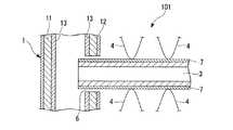
図1は、本発明に係わる熱交換器の一例を示すもので、この熱交換器100は左右に離間し平行に配置されたヘッダーパイプ1、2と、これらのヘッダーパイプ1、2の間に相互に間隔を保って平行に、かつ、ヘッダーパイプ1、2に対して直角に接合された複数の扁平状のチューブ3と、各チューブ3に付設された波形のフィン4を主体として構成されている。ヘッダーパイプ1、2、チューブ3及びフィン4は、後述するアルミニウム合金から構成されている。
より詳細には、ヘッダーパイプ1、2の相対向する側面に複数のスリット6が各パイプの長さ方向に定間隔で形成され、これらヘッダーパイプ1、2の相対向するスリット6にチューブ3の端部を挿通してヘッダーパイプ1、2間にチューブ3が架設されている。また、ヘッダーパイプ1、2間に複数所定間隔で架設されたチューブ3、3の間にフィン4が配置され、これらのフィン4がチューブ3の表面側あるいは裏面側にろう付されている。即ち、図3に示す如く、ヘッダーパイプ1、2のスリット6に対してチューブ3の端部を挿通した部分においてろう材によりフィレット8が形成され、ヘッダーパイプ1、2に対してチューブ3がろう付されている。また、波形のフィン4において波の頂点の部分を隣接するチューブ3の表面または裏面に対向させてそれらの間の部分にろう材によりフィレット9が形成され、チューブ3の表面と裏面に波形のフィン4がろう付されている。
この形態の熱交換器100は、後述する製造方法において詳述するように、ヘッダーパイプ1,2とそれらの間に架設された複数のチューブ3と複数のフィン4とを組み付けて図2に示す如く構成された熱交換器組立体101をろう付けすることにより製造されたものである。Hereinafter, the present invention will be described in detail based on embodiments shown in the accompanying drawings.
FIG. 1 shows an example of a heat exchanger according to the present invention. This
More specifically, a plurality of
The
ろう付前のチューブ3には、フィン4が接合される表面と裏面に、Si粉末:1.0〜5.0g/m2、Zn含有フッ化物系フラックス(KZnF3):4.0〜10.0g/m2、バインダ(例えば、アクリル系樹脂):0.5〜3.0g/m2からなるろう付用塗膜(ろう材塗膜7)が形成されている。In the
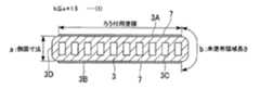
本実施形態のチューブ3は、その内部に複数の通路3cが形成されるとともに、平坦な表面(上面)3A及び裏面(下面)3Bと、これら表面3A及び裏面3Bに隣接する側面3Dとを具備し、図4と図5の横断面に示す如き偏平多穴管として構成されている。
そして、一例としてろう付前のチューブ3の表面3Aと裏面3Bにおいて、チューブ3の長さ方向に直交する方向の幅方向両端部に未塗布部3Eを所定幅で残すようにして前記ろう付用塗膜7が形成されている。
ここで、前記チューブ3の厚さに相当する一側面の幅(高さ)をaとし、この一側面3D(その両側に位置するチューブ表面側未塗布部3E及びチューブ裏面側未塗布部3Eとを含む)全体の塗膜未塗布領域の幅をbとすると、b≦a×1.5の関係を満足することが好ましい。The
As an example, on the
Here, the width (height) of one side surface corresponding to the thickness of the
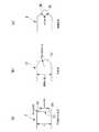
図4、図5に示す構造のチューブ3の側面3Dは、一例として、図6(a)に示す如くチューブ3の端部を横断面視した場合、平坦面3Gとその上下両側のR形状のコーナ部3Hの複合形状とされている。具体寸法の一例として、チューブ3の厚み(側面寸法)をXとして、側面3Dの平坦面3Gの幅Lを0.45Xとし、コーナ部のRの部分を0.275Xとする寸法を例示することができる。
また、チューブ3の側面形状の他の例として、図6(b)に示す如くチューブ3の端部を横断面視した場合、側面3Jの全体が円弧状であり、チューブ3の厚み(側面寸法)をXとして、R≧1.003(X/2)の関係とすることができる。更に、チューブ3の側面形状の他の例として、図6(c)に示す如くチューブ3の端部を横断面視した場合、2つの斜面3Kから断面三角形状に側面を形成し、それら2つの斜面3Kの挟む角度である狭角θ>84゜の関係とすることができる。なお、図6(b)に示すR≧1.003(X/2)の数値と図6(c)で示すθ>84゜の数値は、それぞれ本発明で規定するb≦a×1.5の条件となるようにした限界の値を示している。The
As another example of the side surface shape of the
図4〜図6に示す横断面形状のチューブ3を適用し、後述する組成のアルミニウム合金からチューブ3を形成し、フィン4を後述の組成のアルミニウム合金から形成し、ろう付用塗膜7を後述の組成物とした場合、チューブ3と、フィレット9によりチューブ3に接合されるフィン4とからなる構造物においては、ろう付用塗膜7が設けられていないチューブの側面3D側が防食されるカソード部となり、フィン4及びフィレット9が優先(犠牲)腐食されるアノード部となる。
優先腐食されるアノード部(フィン4とフィレット9)の腐食速度は、カソード部(チューブ3の側面3D側)とアノード部の面積比に大きく影響を受け、カソード部(チューブ3の側面3D側)の面積比が小さいほどアノード部(フィン4とフィレット9)の腐食速度は遅くなる。
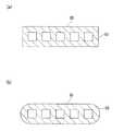
そこで、例えば、チューブ30の側面S1を図7(a)に示す如く平坦にすれば、例えば図7(b)に示すような円弧面S2を有するチューブ31に比べて未塗布部である側面側の面積を相対的に減らすことになり、フィレット9の腐食速度を低減できるので、フィン4の脱落を抑制できるという面において望ましい構造となる。
チューブ3の構造において、Znのないチューブ側面3D側(カソード部)の面積を小さくすることで腐食促進を抑え、フィレット9の優先腐食を抑制してフィン4の脱落を防止できる。チューブ3において側面3D側の面積を小さくするには、側面においてできるだけ直線部を多くすることが有効になる。The
The corrosion rate of the preferentially corroded anode part (
Therefore, for example, if the side surface S1 of the
In the structure of the
以下、ろう付用塗膜を構成する組成物について説明する。
<Si粉末>
Si粉末は、チューブ3を構成するAlと反応し、フィン4とチューブ3を接合するろうを形成するが、ろう付時にSi粉末が溶融してろう液となる。このろう液にフラックス中のZnが均一に拡散し、チューブ3の表面に均一に広がる。液相であるろう液内でのZnの拡散速度は固相内の拡散速度より著しく大きいので、チューブ3表面のZn濃度がほぼ均一となり、これにより均一なZn拡散層が形成され、チューブ3の耐食性を向上することができる。Hereinafter, the composition which comprises the coating film for brazing is demonstrated.
<Si powder>
The Si powder reacts with Al constituting the
Si粉末塗布量:1.0〜5.0g/m2
Si粉末の塗布量が1.0g/m2未満であると、ろう付性が低下し、一方、塗布量が5.0g/m2を超えると、過剰なろう形成によりフィレットにZnが濃縮しやすく、また、チューブの腐食深さが大きくなり、フィンの脱落を防止しようとする目的の効果が得られない。このため、塗膜におけるSi粉末の含有量は1.0〜5.0g/m2とする。
Si粉末粒度:D(50):1〜6μm
Si粉末の粒度が1μm未満であるとフィン4の未接合が増加し、残留率が低下する一方、6μmを超えるとチューブ3の腐食深さが増加する。このため、Si粉末の粒度は、1〜6μmとするのが好ましい。なお、D(50)とは、体積割合で小さい粒から累積し、全体の50%となる粒の粒径のことである。これは、レーザ光散乱法で測定することができる。Si powder coating amount: 1.0 to 5.0 g / m2
When the coating amount of the Si powder is less than 1.0 g / m2 , the brazing property is lowered. On the other hand, when the coating amount exceeds 5.0 g / m2 , Zn is concentrated in the fillet due to excessive brazing. In addition, the corrosion depth of the tube increases, and the intended effect of preventing the fin from falling off cannot be obtained. For this reason, content of Si powder in a coating film shall be 1.0-5.0 g / m <2 >.
Si powder particle size: D (50): 1-6 μm
When the particle size of the Si powder is less than 1 μm,
<Zn含有フッ化物系フラックス>
Zn含有フッ化物系フラックスは、ろう付に際し、チューブ3の表面にZn拡散層を形成し、耐孔食性を向上させる効果がある。また、ろう付時にチューブ3の表面の酸化物を除去し、ろうの広がり、ぬれを促進してろう付性を向上させる作用を有する。
フラックス塗布量:4.0〜10.0g/m2
Zn含有フッ化物系フラックスの塗布量が4.0g/m2未満であると、Zn拡散層の形成が不十分になり、チューブ3の耐食性が低下する。また、被ろう付材(チューブ3)の表面酸化皮膜の破壊除去が不十分なためにろう付不良を招く。一方、塗布量が10.0g/m2を超えると、フィレットの特に共晶部のZn濃縮が顕著になり、フィレットの耐食性が低下して、フィン脱落を加速する。このため、Zn含有フッ化物系フラックスの塗布量を4.0〜10.0g/m2とする。
Zn含有フッ化物系フラックスは、KZnF3を用いることができる。<Zn-containing fluoride flux>
The Zn-containing fluoride flux has an effect of improving the pitting corrosion resistance by forming a Zn diffusion layer on the surface of the
Flux application amount: 4.0 to 10.0 g / m2
When the coating amount of the Zn-containing fluoride-based flux is less than 4.0 g / m2 , the formation of the Zn diffusion layer becomes insufficient, and the corrosion resistance of the
KZnF3 can be used as the Zn-containing fluoride-based flux.
フラックス粒度:D(50):1〜6μm
フラックスの粒度が1μm未満であると、凝集によるチューブ3の腐食深さが増加し、6μmを超えるとフィン4の未接合が増加し、残留率が低下する。このため、フラックスの粒度は1〜6μmが好ましい。なお、D(50)とは、体積割合で小さい粒から累積し、全体の50%となる粒の粒径のことである。これは、レーザ光散乱法で測定することができる。Flux particle size: D (50): 1-6 μm
When the particle size of the flux is less than 1 μm, the corrosion depth of the
<バインダ>
塗布物には、Si粉末、Zn含有フッ化物系フラックスに加えてバインダを含む。バインダの例としては、好適にはアクリル系樹脂を挙げることができる。
バインダの塗布量が0.5g/cm2未満であると、加工性(耐剥離性)が低下する。一方、バインダの塗布量が3.0g/cm2を超えると、ろう付性が低下する。このため、バインダの塗布量は、0.5〜3.0g/m2とする。なお、バインダは、通常、ろう付の際の加熱により蒸散する。<Binder>
The coated material contains a binder in addition to Si powder and Zn-containing fluoride flux. An example of the binder is preferably an acrylic resin.
When the coating amount of the binder is less than 0.5 g / cm2 , workability (peeling resistance) decreases. On the other hand, when the coating amount of the binder exceeds 3.0 g / cm2 , the brazing property is lowered. For this reason, the application quantity of a binder shall be 0.5-3.0 g / m <2 >. The binder usually evaporates by heating during brazing.
Si粉末、フラックス及びバインダからなるろう付組成物の塗布方法は、本発明において特に限定されるものではなく、スプレー法、シャワー法、フローコータ法、ロールコータ法、刷毛塗り法、浸漬法、静電塗布法などの適宜の方法によって行うことができる。また、ろう付組成物の塗布領域は、チューブ3の全表面としてもよく、また、チューブ3の一部表面とするものであってもよく、要は、少なくともフィン4をろう付するのに必要なチューブ3の表面領域に塗布されていればよい。また、本願のチューブ3は側面にろう付組成物が形成されていないものであるが、塗布方法によっては上面等にろう付組成物を塗布した場合、結果的に側面にも一部形成されてしまうことがあるが、このようなものを本発明では排除しない。 The method for applying the brazing composition comprising the Si powder, the flux and the binder is not particularly limited in the present invention. The spray method, the shower method, the flow coater method, the roll coater method, the brush coating method, the dipping method, the static method. It can be performed by an appropriate method such as an electrocoating method. The brazing composition application area may be the entire surface of the
チューブ3は、質量%で、Mn:0.15〜0.45%、Si:0.20〜0.50%、残部がアルミニウム及び不可避的不純物からなるアルミニウム合金を押出しによって作製されたものである。
以下、チューブ3を構成するアルミニウム合金の各構成元素の限定理由について説明する。
<Mn:0.15〜0.45%>
Mnは、チューブ3の耐食性を向上するとともに、機械的強度を向上させる元素である。また、Mnは、押出し成形時の押出性を向上する効果をも有する。更にMnは、ろうの流動性を抑制し、フィレットとチューブ表面のZn濃度差を小さくする効果がある。
Mnの含有量が0.15%未満では、耐食性及び強度向上の効果が不十分であり、ろうの流動性を抑制する効果も低下する一方、Mnが0.45%を超えて含有すると、押出圧力増により押出性が低下する。したがって本発明におけるMn含有量は、0.15〜0.45%にする。好ましいMnの含有量は、0.20〜0.40%である。
<Si:0.20〜0.50%>
SiもMnと同様に強度と耐食性向上効果を有する元素である。
Siの含有量が0.20%未満では、耐食性及び強度向上の効果が不十分であり、一方、Siが0.50%を超えて含有すると、押出性が低下する。したがって本発明におけるSi含有量は、0.20〜0.50%にする。好ましいSiの含有量は、0.25〜0.45%である。The
Hereinafter, the reasons for limiting the constituent elements of the aluminum alloy constituting the
<Mn: 0.15 to 0.45%>
Mn is an element that improves the corrosion resistance of the
If the Mn content is less than 0.15%, the effect of improving the corrosion resistance and strength is insufficient, and the effect of suppressing the fluidity of the wax is reduced. On the other hand, if the Mn content exceeds 0.45%, the extrusion Extrudability decreases with increasing pressure. Therefore, the Mn content in the present invention is 0.15 to 0.45%. A preferable Mn content is 0.20 to 0.40%.
<Si: 0.20 to 0.50%>
Si, like Mn, is an element having an effect of improving strength and corrosion resistance.
If the Si content is less than 0.20%, the effect of improving the corrosion resistance and strength is insufficient. On the other hand, if the Si content exceeds 0.50%, the extrudability decreases. Therefore, the Si content in the present invention is 0.20 to 0.50%. A preferable Si content is 0.25 to 0.45%.
次に、フィン4について説明する。
チューブ3に接合されるフィン4は、質量%で、Zn:1.20〜1.80%、Si:0.70〜1.20%、Fe:0.30〜0.80%、Mn:0.90〜1.50%を含有し、更に、Zr:0.05〜0.20%、V:0.01〜0.10%及びCr:0.01〜0.10%の1種又は2種以上を含有し、残部Al及び不可避的不純物からなるアルミニウム合金から構成される。フィン4は、上記組成を有するアルミニウム合金を常法により溶製し、熱間圧延工程、冷間圧延工程などを経て、波形形状に加工される。なお、フィン4の製造方法は、本発明としては特に限定をされるものではなく、既知の製法を適宜採用することができる。以下、フィン4を構成するアルミニウム合金の各構成元素の限定理由について説明する。
<Zn:1.20〜1.80%>
Znを含有することによって電位を下げて、フィン4に犠牲防食効果を付与する。
Znの含有量が1.20%未満では、犠牲防食効果が不十分であり、一方、Znの含有量が1.80%を超えると、ろう付時にフィレット9にもZnが多く拡散し、フィレット9のZn濃度が増加し、フィレット9をフィン4より先に腐食させてしまう。また、フィン4の腐食速度が促進され、短期間で消耗するため、犠牲フィンとしての効果期間が短くなる。したがって本願発明におけるZnの含有量は、1.20〜1.80%にする。好ましいZnの含有量は、1.45〜1.55%である。Next, the
The
<Zn: 1.20 to 1.80%>
By containing Zn, the potential is lowered, and a sacrificial anticorrosive effect is imparted to the
If the Zn content is less than 1.20%, the sacrificial anticorrosive effect is insufficient. On the other hand, if the Zn content exceeds 1.80%, a large amount of Zn diffuses into the
<Si:0.70〜1.20%>
Siを含有することによって、フィン4の高温及び室温強度を向上させる。
Siの含有量が0.70%未満では、高温及び室温強度向上効果が不十分であり、一方、Siの含有量が1.20%を超えると、フィン4を作製する際に加工性の低下を招く。したがって、本願発明におけるSiの含有量は、0.70〜1.20%にする。好ましいSiの含有量は、0.95〜1.10%である。
<Fe:0.30〜0.80%>
FeはSiと同様にフィン4の高温及び室温強度を向上させる。
Feの含有量が0.30%未満では、高温及び室温強度向上効果が不十分であり、一方、Feの含有量が0.80%を超えると、フィン4を作製する際に加工性が不足し、フィン4自身の耐食性を低下させる。したがって、本願発明におけるFeの含有量は、0.30〜0.80%にする。好ましいFeの含有量は、0.47〜0.53%である。<Si: 0.70 to 1.20%>
By containing Si, the high temperature and room temperature strength of the
If the Si content is less than 0.70%, the effect of improving the high temperature and room temperature strength is insufficient. On the other hand, if the Si content exceeds 1.20%, the workability decreases when the
<Fe: 0.30 to 0.80%>
Fe improves the high temperature and room temperature strength of the
If the Fe content is less than 0.30%, the effect of improving the high temperature and room temperature strength is insufficient. On the other hand, if the Fe content exceeds 0.80%, the workability is insufficient when the
<Mn:0.90〜1.50%>
MnもSiと同様にフィン4の高温及び室温強度を向上させる。
Mnの含有量が0.90%未満では、高温及び室温強度向上効果が不十分であり、一方、Mnの含有量が1.50%を超えると、フィン4を作製する際に加工性が不足する。したがって、本願発明におけるMnの含有量は、0.90〜1.50%にする。好ましいMnの含有量は、1.15〜1.25%である。
Si、Feを上記範囲に設定すると、Si、Feは各々Mnと析出物を形成させ、Mn固溶量を減らし、フィン4の電位を下げる。これにより、フィレット9の初晶部よりフィン4を優先的に腐食させて、フィン4の脱落を抑制する。<Mn: 0.90 to 1.50%>
Mn also improves the high temperature and room temperature strength of the
If the Mn content is less than 0.90%, the effect of improving the high temperature and room temperature strength is insufficient. On the other hand, if the Mn content exceeds 1.50%, the workability is insufficient when producing the
When Si and Fe are set within the above ranges, Si and Fe each form precipitates with Mn, reduce the Mn solid solution amount, and lower the potential of the
<Zr:0.05〜0.20%>
ZrもSiと同様にフィン4の高温及び室温強度を向上させる。
Zrの含有量が0.05%未満では、高温及び室温強度向上効果が不十分であり、一方、Zrの含有量が0.20%を超えると、フィン4を作製する際に加工性が不足する。したがって、本願発明におけるZrの含有量は、0.05〜0.20%にする。好ましいZrの含有量は、0.10〜0.15%である。
<V:0.01〜0.10%>
VもSiと同様にフィン4の高温及び室温強度を向上させる。
Vの含有量が0.01%未満では、高温及び室温強度向上効果が不十分であり、一方、Vの含有量が0.10%を超えると、フィン4を作製する際に加工性が不足する。したがって、本願発明におけるVの含有量は、0.01〜0.10%にする。好ましいVの含有量は、0.02〜0.08%である。<Zr: 0.05 to 0.20%>
Zr improves the high temperature and room temperature strength of the
If the Zr content is less than 0.05%, the effect of improving the high temperature and room temperature strength is insufficient. On the other hand, if the Zr content exceeds 0.20%, the workability is insufficient when the
<V: 0.01 to 0.10%>
V, like Si, improves the high temperature and room temperature strength of the
If the V content is less than 0.01%, the effect of improving the high temperature and room temperature strength is insufficient. On the other hand, if the V content exceeds 0.10%, the workability is insufficient when the
<Cr:0.01〜0.10%>
CrもSiと同様にフィン4の高温及び室温強度を向上させる。
Crの含有量が0.01%未満では、高温及び室温強度向上効果が不十分であり、一方、Crの含有量が0.10%を超えると、フィン4を作製する際に加工性が不足する。したがって、本願発明におけるCrの含有量は、0.01〜0.10%にする。好ましいCrの含有量は、0.02〜0.08%である。
本発明において、Zr、V及びCrは、1種又は2種以上含有される。<Cr: 0.01 to 0.10%>
Cr, like Si, improves the high temperature and room temperature strength of the
If the Cr content is less than 0.01%, the effect of improving the high temperature and room temperature strength is insufficient. On the other hand, if the Cr content exceeds 0.10%, the workability is insufficient when the
In the present invention, Zr, V and Cr are contained singly or in combination.
次に、ヘッダーパイプ1について説明する。
ヘッダーパイプ1は、図2、図3に示すように、芯材層11と、芯材の外周側に設けられた犠牲材層12と、芯材の内周側に設けられたろう材層13とからなる3層構造をなしている。
芯材層11の外周側に犠牲材層12を設けることにより、フィン4による防食効果に加えてヘッダーパイプ1による防食効果も得られるため、ヘッダーパイプ1近傍のチューブ3の犠牲防食効果をより高めることができる。Next, the
2 and 3, the
By providing the
芯材層11は、Al−Mn系をベースとした合金が好ましい。
例えば、Mn:0.05〜1.50%を含有することが好ましく、他の元素として、Cu:0.05〜0.8%、Zr:0.05〜0.15%を含有することができる。The
For example, it is preferable to contain Mn: 0.05 to 1.50%, and as other elements, Cu: 0.05 to 0.8%, Zr: 0.05 to 0.15% may be contained. it can.
芯材層11の外周側に設けられる犠牲材層12は、Zn:0.60〜1.20%、残部Al及び不可避的不純物からなるアルミニウム合金から構成される。犠牲材層12は、クラッド圧延により芯材層11と一体化されている。各構成元素の限定理由は以下の通りである。
<Zn:0.60〜1.20%>
Znは、犠牲材層12に犠牲防食効果を付与する元素である。
Znの含有量が0.60%未満では犠牲防食効果が不十分であり、一方、Znの含有量が1.20%を超えると犠牲材層12自体の耐食性が低下する。したがって、犠牲材層12におけるZnの含有量は、0.60〜1.20%にする。好ましいZnの含有量は、0.70〜1.10%である。
犠牲材層12は、芯材層11に対するクラッド率が5〜10%であることが好ましい。犠牲材層12のクラッド率が5%未満では、犠牲防食効果が不十分であり、クラッド率が10%を超えても、それに応じた犠牲防食効果が得られないからである。The
<Zn: 0.60 to 1.20%>
Zn is an element that imparts a sacrificial anticorrosive effect to the
If the Zn content is less than 0.60%, the sacrificial anticorrosive effect is insufficient. On the other hand, if the Zn content exceeds 1.20%, the corrosion resistance of the
The
芯材層11の内周側に設けられるろう材層13は、Al−Si系合金が好ましい。Al−Si合金は、Si:5.0〜11.5%を含有することが好ましい。
ろう材層13は、クラッド圧延により芯材層11と一体化されている。ろう材層13は、芯材層11に対するクラッド率が3〜10%であることが好ましい。ろう材層13のクラッド率が3%未満では、フィレット8を構成するろう材が不十分であり、クラッド率が10%を超えるとろう材が過剰となるからである。The
The
次に、以上説明したヘッダーパイプ1、2チューブ3及びフィン4を主たる構成要素とする熱交換器100の製造方法について説明する。
図2は、フィン4との接合面にろう材層13を塗布したチューブ3を使用して、ヘッダーパイプ1、2、チューブ3及びフィン4を組み立てた状態を示す熱交換器組立体101の部分拡大図であって、加熱ろう付する前の状態を示している。図2に示す熱交換器組立体101において、チューブ3はその一端をヘッダーパイプ1に設けたスリット6に挿入し取付けられている。
図2に示すように組み立てられたヘッダーパイプ1、2、チューブ3及びフィン4からなる熱交換器組立体101をろう材の融点以上の温度に加熱すると、図3に示すように、ろう材層13が溶けてヘッダーパイプ1とチューブ3、チューブ3とフィン4が各々接合され、図1と図3に示す構造の熱交換器100が得られる。この時、ヘッダーパイプ1の内周面のろう材層13は溶融してスリット6近傍に流れ、フィレット8を形成してヘッダーパイプ1とチューブ3とが接合される。また、チューブ3の表面のろう付用塗膜7は溶融して毛管力によりフィン4近傍に流れ、フィレット9を形成してチューブ3とフィン4とが接合される。Next, the manufacturing method of the
FIG. 2 shows a part of the
When the
ろう付に際しては、不活性雰囲気などの適切な雰囲気で適温に加熱して、ろう付用塗膜7、ろう材層13を溶解させる。そうすると、フラックスの活性度が上がって、フラックス中のZnが被ろう付材(チューブ3)表面に析出し、その肉厚方面に拡散するのに加え、ろう材及び被ろう付材の双方の表面の酸化皮膜を破壊してろう材と被ろう付材との間のぬれを促進する。
ろう付のための加熱温度は、上述したように、ろう材の融点以上であるが、上述した組成からなるろう材の場合、580〜615℃に加熱され、1〜10分程度保持される。本実施の形態では、この加熱の昇温過程の530〜575℃の温度粋で、4〜8分間保持する。この昇温過程での保持の期間内に、フラックスに含まれているZnをチューブ3の表面に拡散させ、定着させる。そうすることにより、フィレット9へ流動するZn量を低減し、フィン4の脱落を抑制する。At the time of brazing, the
As described above, the heating temperature for brazing is equal to or higher than the melting point of the brazing material, but in the case of the brazing material having the above-described composition, it is heated to 580 to 615 ° C. and held for about 1 to 10 minutes. In the present embodiment, the temperature is maintained at 530 to 575 ° C. in the heating process for 4 to 8 minutes. Zn contained in the flux is diffused and fixed on the surface of the
保持の温度が530℃未満、又は保持の時間が4分未満ではZnがチューブ3表面へ十分に拡散できず、フィレット9に流動するろう材に含まれるZnの量が多くなる。一方、保持の温度が575℃を超え、又は8分を超えると、チューブ3の内部側へのZn拡散が過剰となり、良好な犠牲防食層が形成できずチューブ3の耐食性が低下する。したがって、昇温過程での保持の条件は、温度域:530〜575℃、時間:4〜8分とすることが好ましい。
本発明において、昇温過程の保持は、一定の温度でなされる必要はない。例えば、530〜575℃の温度域を4〜8分かけて通過してもよいし、570℃(一定)を4〜8分間保持してもよい。要は、530〜575℃の温度域に4〜8分間晒すことができればよい。If the holding temperature is less than 530 ° C. or the holding time is less than 4 minutes, Zn cannot sufficiently diffuse to the surface of the
In the present invention, the temperature raising process need not be held at a constant temperature. For example, a temperature range of 530 to 575 ° C. may be passed over 4 to 8 minutes, or 570 ° C. (constant) may be held for 4 to 8 minutes. In short, it should just be exposed to the temperature range of 530-575 degreeC for 4 to 8 minutes.
ろう付に際しては、チューブ3を構成するアルミニウム合金のマトリックスの一部がチューブ3に塗布されたろう付用塗膜7の組成物と反応してろうとなって、チューブ3とフィン4とがろう付される。チューブ3の表面ではろう付によってフラックス中のZnが拡散してチューブ3内側よりも卑になる。 At the time of brazing, a part of the aluminum alloy matrix constituting the
本実施の形態によれば、ろう付に際して、Si粉末の残渣もなく、良好なろう付がなされ、チューブ3とフィン4との間に十分なサイズのフィレット9が形成される。また、フィレット9のサイズ増大化によってフィレット9へのZn濃縮は抑制される。
得られた熱交換器100は、チューブ3の表面に適度なZn層が形成されて孔食が防止され、また、フィレット9の腐食が抑制され、長期に亘ってチューブ3とフィン4とが確実に接合されたままとなり、良好な熱交換性能が維持される。According to the present embodiment, when brazing, there is no residue of Si powder and good brazing is performed, and a
In the obtained
本実施の形態の熱交換器100の製造方法において、ろう付温度まで加熱して昇温する途中で530〜575℃の温度域で4〜8分保持した後、ろう付温度まで加熱することにより、ろうが流動する前のZnがチューブへ拡散する温度域で保持することができるので、より多くのZnをチューブ3内部側へ拡散することができ、フィレット9への過剰なZn濃縮を抑制することができる。従ってフィレット9の優先腐食を抑制することができ、熱交換器100におけるフィン4の脱落を抑制できる。 In the manufacturing method of the
前述の如く得られた熱交換器100によれば、チューブ3にMn:0.15〜0.45%とSi:0.20〜0.50%の適正量を添加することにより、従来の1050材やAl−Cu系合金よりも耐食性に優れ、犠牲防食層のためのフラックスのZn量を低減でき、具体的には4.0〜10.0g/m2の範囲にできるので、ろうとともにフィレット9へ流動するZn量を低減することができ、フィレット9の優先腐食を抑制できるので、フィン4の脱落を防止できる。
本実施形態の熱交換器100によれば、チューブ3に添加したMnはろう付のろうの流動性を抑制するため、ろう付時の加熱により生じたろうが過剰にフィレット9へ流動することがなくなり、一部チューブ3の表面にも残留するので、フィレット9とチューブ3の表面のZn濃度差を小さくすることができ、フィレット9の優先腐食を抑制できるので、フィン4の脱落を防止できる。According to the
According to the
本実施形態の熱交換器100によれば、フィン4にSi:0.7〜1.20%とFe:0.30〜0.80%を適正量添加しているので、Si、Fe及びMnの金属間化合物を生成することができ、フィン4の犠牲防食効果を向上させるので、犠牲防食層のためのフィンのZn量を低減することができる。その結果、図8に示す如くフィン4からフィレット9へのZn拡散(フィレット9におけるZn濃縮)を低減することができ、フィレット9の優先腐食を防止し、フィン4の脱落を防止できる。
従って本実施形態の熱交換器100によれば、フィレット9の優先腐食によるフィン4の脱落が従来よりも低減された熱交換器100を提供することができる。
また、本実施形態の熱交換器100によれば、フィン4が脱落し難いため、フィン4によるチューブ3の犠牲防食をより長期間得ることができ、その結果、チューブ3の腐食寿命を従来よりも延ばすことが可能になる。According to the
Therefore, according to the
Moreover, according to the
本実施形態の熱交換器100において、フィン4をろう付するチューブ3の表面または裏面に対し、未塗布部を残してろう付用塗膜を形成し、チューブ3側面の未塗布部領域の全幅をチューブの厚さの1.5倍以内とすることが好ましい。
本発明のチューブ3にフィン4がろう付された熱交換器100にあっては、Znのある部位がアノード部になり、アノード部が優先腐食されることによってカソード部となるZnの無い部位を防食する。即ち、カソード部となるZnの無い部位(チューブ側面側面積)が大きい程、アノード部となるZnのある部位(ろう材塗布面)が犠牲防食のため、より腐食されることになる。
従って、チューブ3においてZnを供給していない領域をできるだけ小さくすることで腐食促進を抑え、フィレット9の優先腐食を抑制でき、フィン4の脱落を抑制できる。In the
In the
Therefore, by making the area | region which does not supply Zn in the
本実施形態の熱交換器100において表面積の大きいヘッダーパイプ1、2の外表面もチューブ3の側面と同様にヘッダーパイプ1、2の近傍の接合部であるフィレット9の腐食に影響を与える。ヘッダーパイプ1、2の表面積は特に大きいのでその影響度も大きい。
図9に示す如くヘッダーパイプ1、2が芯材層11と外側の犠牲材層12と内側のろう材層13からなり、犠牲材層12にZnを0.60〜1.20%含有させているとヘッダーパイプ1、2の犠牲層12を優先腐食させることで図9の楕円状の鎖線で囲む位置のフィレット9の優先腐食を抑制することができ、フィン4の脱落を抑制できる。
これに対し図10に示す如くヘッダーパイプ1、2の芯材層11の表面側がZnの無いろう材などからなり、この部位がカソード部であると、フィレット9の腐食を著しく促進し、図10の楕円状の鎖線で囲む部分の如くフィレット9が腐食に伴い消失するとフィン4の接合力が弱くなりフィン4の脱落が発生する。これに対して上述の如く外表面にZnを含有させた犠牲材層12を図9に示す如く配置することでフィレット9の優先腐食(フィン4の脱落)を著しく抑制できる。In the
As shown in FIG. 9, the
On the other hand, as shown in FIG. 10, when the surface side of the
本実施の形態の熱交換器100の製造方法において、ろう付温度まで加熱して昇温する途中で530〜575℃の温度域で4〜8分保持した後、ろう付温度まで加熱することによる作用効果について図11〜図13に基づいて更に説明する。
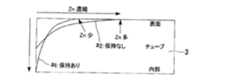
前述の製造方法により530〜575℃の温度域で4〜8分保持することで、より多くのZnがチューブ3の内部側に拡散する。これに対してこの温度保持がない場合、Znはチューブ3の内部側への拡散は少なくなる。これらの状態を対比しながら図11に示すと、530〜575℃の温度域で4〜8分保持ありの場合は、a1曲線に示す如く、チューブ3の深い位置までZnが拡散するが、保持なしの場合は、チューブ3の深い位置までZnが拡散しない。In the manufacturing method of the
By maintaining the temperature in the temperature range of 530 to 575 ° C. for 4 to 8 minutes by the above-described manufacturing method, more Zn diffuses to the inside of the
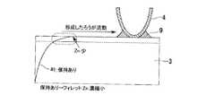
図12に上述の温度保持がない場合のチューブ3における深さ方向のZn濃度分布とフィン4の位置関係を示し、図13に温度保持がある場合のチューブ3における深さ方向のZn濃度分布とフィン4の位置関係を示す。更に図12と図13には、加熱によってろう材中のSiがAlと共晶組成となって浸食される領域が生成するので、この浸食される領域の深さを鎖線によって示した。前述の温度範囲に加熱してろう材が溶融している場合、共晶組成となって溶融した状態でZnの拡散が進行するが、温度保持なしの場合はZnがチューブ3の拡散する深さが浅くなり、チューブ3の表面においてフィン4と接する部分に生成するフィレット9に濃縮するZn量は多くなるのに対し、温度保持ありの場合はZnがチューブ3に深く拡散するのでチューブ3の表面部分に存在してフィレット9に濃縮するZn量は少なくなるので、チューブ3の表面においてフィン4と接する部分のフィレット9に濃縮するZn量は少なくなる。従ってフィレット9の優先腐食を防止し、フィン4の脱落を防止できる。 FIG. 12 shows the positional relationship between the fin concentration and the Zn concentration distribution in the depth direction in the
表1に示す組成のチューブ用Al合金、表2に示す組成のフィン用Al合金を溶製した。また、表3に示す組成の芯材用Al合金、犠牲材層用Al合金、ろう材層用Al合金を溶製した。
チューブ用Al合金を均質加熱処理後、熱間押出で図4、図6(a)に示す横断面形状(肉厚0.30mm×幅18.0mm×全体厚1.5mm:側面の平坦面高さ0.6mm、コーナー部のR:0.45mm)、(側面平坦面高さ0.9mm、コーナ部R:0.3mm)の扁平状のチューブ3を作製した。また、図6(b)と図7(b)に示す側面Sが円弧状(円弧の半径:0.75mm、1.5mm)のチューブ31、図6(c)に示す側面が斜面状(狭角90゜)とされたチューブを作製した。
フィン用Al合金を均質加熱処理後、熱間圧延、冷間圧延することにより厚さ0.08mmの板材を得た。この板材をコルゲート加工することにより、フィン4を作製した。
犠牲材用Al合金、芯材用Al合金及びろう材層用Al合金を、熱間圧延、冷間圧延することにより、各々厚さ0.12mm、1.30mm、0.08mmの板材を得た。芯材用Al合金板を中心にし、その一方の面に犠牲材用Al合金板を配置し、他方の面にろう材層用Al合金板を配置した3層クラッド材からなる断面円形の電縫管を得た。この電縫管に加工を加えることにより、ヘッダーパイプ1を作製した。このヘッダーパイプ1は外側が犠牲層、内側がろう材層である。An Al alloy for tubes having the composition shown in Table 1 and an Al alloy for fins having the composition shown in Table 2 were melted. Also, an Al alloy for the core material, an Al alloy for the sacrificial material layer, and an Al alloy for the brazing material layer having the compositions shown in Table 3 were melted.
After homogeneous heat treatment of the tube Al alloy, the cross-sectional shape shown in FIGS. 4 and 6 (a) by hot extrusion (thickness 0.30 mm × width 18.0 mm × total thickness 1.5 mm: flat height of the side surface) A
A plate material having a thickness of 0.08 mm was obtained by homogeneously heat-treating the Al alloy for fins, followed by hot rolling and cold rolling. The
A plate material having a thickness of 0.12 mm, 1.30 mm, and 0.08 mm was obtained by hot rolling and cold rolling an Al alloy for a sacrificial material, an Al alloy for a core material, and an Al alloy for a brazing material layer, respectively. . Centering on the Al alloy plate for the core material, the cross section circular electro-sewing composed of the three-layer clad material in which the Al alloy plate for the sacrificial material is arranged on one side and the Al alloy plate for the brazing material layer is arranged on the other side Got the tube. The

次に、チューブ3の表面に、ろう材組成物をロール塗布し、乾燥させた。
ろう材組成物は、Si粉末(D(50)粒度2.8μm)、フラックス(KZnF3:D(50)粒度2.0μm)及びアクリル系樹脂(溶剤としてのイソプロピルアルコール等のアルコールを含む)の混合物からなる。各要素の塗布量が表4に示す値となるように混合量を定めた。Next, the brazing material composition was roll-coated on the surface of the
The brazing filler metal composition is composed of Si powder (D (50) particle size 2.8 μm), flux (KZnF3 : D (50) particle size 2.0 μm) and acrylic resin (including alcohol such as isopropyl alcohol as a solvent). Consists of a mixture. The mixing amount was determined so that the application amount of each element was a value shown in Table 4.
次に、ヘッダーパイプ1、チューブ3及びフィン4を図1に示すように熱交換器100に組立て、以下の3種類の条件でろう付を行った。なお、いずれもろう付は、窒素ガス雰囲気の炉中で行った。
条件1:570℃まで昇温し、570℃で4分間保持した後に、600℃まで昇温し、2分間保持 条件2:600℃まで連続的に昇温し、2分間保持(530〜575℃の通過時間6分)
条件3:600℃まで連続的に昇温し、2分間保持(530〜575℃の通過時間1分)
ろう付後、ろう付性の評価を行った。具体的には、33箇所のフィン4の接合部を含む長さ100mmのチューブ3を切り取り、各接合箇所についてフィン幅(18mm)に対するろう付による接合長さの割合を求め、33箇所分について合計の接合率を算出して、ろう付性を評価した。
また、ろう付後、熱交換器100をSWAAT20日間の腐食試験に供した。試験後にチューブ3に生じた腐食の深さ、及びフィン4の残存率(腐食後残存したフィンの長さ/ろう付されていたフィン長×100)を測定した。Next, the
Condition 1: Temperature raised to 570 ° C., held at 570 ° C. for 4 minutes, then heated to 600 ° C. and held for 2 minutes Condition 2: Temperature raised continuously to 600 ° C. and held for 2 minutes (530-575 ° C. 6 minutes)
Condition 3: Temperature is continuously raised to 600 ° C. and held for 2 minutes (passing time of 530 to 575 ° C. for 1 minute)
After brazing, the brazeability was evaluated. Specifically, the
Further, after brazing, the
以上の結果を表4に示すが、表4より以下のことがわかる。
Si粉末の塗布量が少ないとフィン4の脱落が顕著となり、Si粉末の塗布量が多いとチューブ3の耐食性が劣ると同時に脱落も多くなる(No.1〜6参照)。
フラックスの塗布量が少ないとチューブ3の耐食性が劣るとともに、フィン4の未接合が多くなり、フラックスの塗布量が多いとフィン4の脱落が顕著となる(No.7〜12参照)。
バインダの塗布量が少ないか又は多いと、チューブ3の耐食性が劣る(No.16、17参照)。
チューブ3の側面が円弧になり、更に、チューブ3の全体厚さに相当する一側面の幅をaとし、この一側面の塗膜未塗布領域の幅をbとすると、b≦a×1.5の関係を満足することが好ましいが、この値が1.50を超えるNo.18の試料はフィン4の脱落発生割合が若干高くなり、フィン4の脱落性の面で劣るようになる。チューブ3の側面が円弧であっても、b≦a×1.5の関係を満足するNo.21の試料は、耐食性とフィン残存率の両方に優れている。
ろう付の昇温過程の530〜575℃の通過時間を6分と長くすれば、チューブ3の耐食性を向上できる(No.19参照)とともに、フィン4の脱落を抑制できる。しかし、ろう付の昇温過程の530〜575℃の通過時間を1分と短くすれば、フィン4の脱落が多くなる(No.20参照)。
チューブ3の側面形状について、2つの斜面からなり、それらの面が形成する狭角θ:90度のNo.23の試料はb=a×1.41であり、耐食性とフィン残存率のいずれにおいても優れていた。
なお、チューブ腐食深さは、75μm以下、フィン残留率は70%以上が目標値である。The above results are shown in Table 4, and Table 4 shows the following.
If the amount of Si powder applied is small, the
When the application amount of the flux is small, the corrosion resistance of the
When the coating amount of the binder is small or large, the corrosion resistance of the
The side surface of the
If the passage time of 530 to 575 ° C. in the brazing temperature raising process is increased to 6 minutes, the corrosion resistance of the
Regarding the side surface shape of the
The tube corrosion depth is 75 μm or less, and the fin residual ratio is 70% or more.
「実施例2」
チューブ用アルミニウム合金の組成を表5に示すものとした以外は、実施例1と同様にして熱交換器100を作製し、チューブ3に生じた腐食の深さ及びフィン4の残存率を測定した。結果を表5に示す。なお、チューブ3に塗布するろう付組成物は、表4のNo.4を採用した。"Example 2"
A
表5に示すように、チューブ3のMn含有量及びSi含有量によりチューブ3の耐食性、フィン4の残存率が変動する。そこで、Mn:0.15〜0.45%、Si:0.20〜0.50%を本発明の好ましい範囲とした。 As shown in Table 5, the corrosion resistance of the
「実施例3」
フィン用アルミニウム合金の組成を表6に示すものとした以外は、実施例1と同様にして熱交換器100を作製し、チューブ3に生じた腐食の深さ及びフィン4の残存率を測定した。結果を表6に示す。なお、チューブ3に塗布するろう付組成物は、表4のNo.4を採用した。"Example 3"
A
表6に示すように、フィン4を構成する合金の構成元素の含有量によりチューブ3の耐食性、フィン4の残存率が変動する。そこで、Zn:1.20〜1.80%、Si:0.70〜1.20%、Fe:0.30〜0.80%、Mn:0.90〜1.50%の範囲であることが、高いフィンチューブ接合率を得るため、耐食性に優れるために必要であり、かつ、フィン残存率も高くするために必要であると判明した。また、ZrとVとCrについては、Zr:0.05〜0.20%、V:0.01〜0.10%、Cr:0.01〜0.10%の範囲であることが、本発明の好ましい範囲であることも判明した。 As shown in Table 6, the corrosion resistance of the
「実施例4」
ヘッダーパイプ用合金の組成を表7に示すものとした以外は、実施例1と同様にして熱交換器100を作製し、チューブ3に生じた腐食の深さ及びフィン4の残存率を測定した(表7 No.62〜66)。また、ヘッダーパイプ1を、内周側に犠牲材層を、また外周側にろう材層を配置した構成とした以外は、実施例1と同様にして熱交換器100を作製し、チューブ3に生じた腐食の深さ及びフィン4の残存率を測定した(表7 No.67)。結果を表7に示す。なお、チューブ3に塗布するろう付組成物は、表4のNo.4を採用した。Example 4
A
表7に示すように、犠牲材層12を構成する合金のZn含有量が少ないか多いと、チューブ3の耐食性、フィン4の残存率が劣る傾向にある(No.62、65)。そこで、Zn:0.60〜1.20%を本発明の好ましい範囲とした。
また、ヘッダーパイプ1を、内周側に犠牲材層を、また外周側にろう材層を配置した構成とすると、チューブ3の耐食性、フィン4の残存率が劣ることがわかる(表7 No.67)。
また、表7のNo.66の試料に示すようにヘッダーパイプの外側に犠牲層を設けることなく、外側にのみろう材層を設けた構造とすると、耐食性とフィン残留率の両方が劣ることが判る。As shown in Table 7, when the Zn content of the alloy constituting the
Further, when the
Moreover, as shown in the sample of No. 66 in Table 7, when a brazing material layer is provided only on the outer side without providing a sacrificial layer on the outer side of the header pipe, both corrosion resistance and fin residual ratio may be inferior. I understand.
100…熱交換器、101…熱交換器組立体、1、2…ヘッダーパイプ、11…芯材層、12…犠牲材層、13…ろう材層、3、30、31…チューブ、3A…表面(上面)、3B…裏面(下面)、3C…通路、3D…側面、3E…未塗布部、3G…平坦面、3H…コーナ部、3J…側面、3K…斜面、4…フィン、6…スリット、7…ろう付用塗膜(ろう材塗膜)、8、9…フィレット、a…厚さ(側面寸法)、b…未塗布領域長さ(未塗布領域幅)。 DESCRIPTION OF
Claims (8)
Translated fromJapanese前記フィンは、Zn:1.20〜1.80%、Si:0.70〜1.20%、Fe:0.3〜0.8%、Mn:0.90〜1.50%を含有し、更に、Zr:0.05〜0.20%、V:0.01〜0.10%及びCr:0.01〜0.10%の1種又は2種以上を含有し、残部がAl及び不可避不純物であり、前記ヘッダーパイプは、芯材層と、外側の犠牲材層と、内側のろう材層を具備し、
ろう付け時に前記ろう付け用塗膜から生成したSiを含むろう液を介しZnを前記チューブ表面から内部に拡散させ、該チューブと前記フィンとの間および前記チューブと前記ヘッダーパイプとの間にフレットを形成したろう付けにより前記フィンは前記チューブに接合され、前記チューブは前記ヘッダーパイプに接合されていることを特徴とする熱交換器。A heat exchanger configured by combining a fin and a header pipe to a tube, wherein the composition of the tube is Mn:0.2 to 0.4 %, Si: 0.20 to 0.50%, and the balance is Al and unavoidable impurities, on the surface to which the fins of the tube are joined, a Si powder of 1.0 to 5.0 g / m2 , a flux of KZnF3 of 4.0 to 10.0 g / m2 , a binder A coating film for brazing consisting of 0.5 to 3.0 g / m2 is formed,
The fin contains Zn: 1.20 to 1.80%, Si: 0.70 to 1.20%, Fe: 0.3 to 0.8%, Mn: 0.90 to 1.50%. Further, it contains one or more of Zr: 0.05 to 0.20%, V: 0.01 to 0.10% and Cr: 0.01 to 0.10%, with the balance being Al and Inevitable impurities, the header pipe comprises a core material layer, an outer sacrificial material layer, and an inner brazing material layer,
Zn is diffused from the surface of the tube through the brazing solution containing Si generated from the brazing coating during brazing, and frets are formed between the tube and the fin and between the tube and the header pipe. The heat exchanger is characterized in that the fin is joined to the tube by brazing, and the tube is joined to the header pipe.
前記チューブの厚さに相当する一側面の幅をaとし、この一側面全体の塗膜未塗布領域の幅をbとすると、b≦a×1.5の関係を満足することを特徴とする請求項1〜請求項4のいずれか一項に記載の熱交換器。The tube is a flat type, and on the front or back surface to which the fin is connected, the coating film for brazing is formed by leaving uncoated portions at both ends in the width direction in the direction orthogonal to the length direction of the tube. The brazing film is not formed on the side surface adjacent to the front or back surface of the tube,
When the width of one side corresponding to the thickness of the tube is a and the width of the uncoated region of the entire side is b, the relationship of b ≦ a × 1.5 is satisfied. The heat exchanger accordingto any one of claims 1 to 4 .
前記チューブの組成が、Mn:0.2〜0.4%、Si:0.20〜0.50%、残部がAl及び不可避不純物であり、前記チューブのフィンが接合される面に、Si粉末1.0〜5.0g/m2と、KZnF3からなるフラックス4.0〜10.0g/m2と、バインダ0.5〜3.0g/m2とからなるろう付用塗膜が形成され、
前記フィンは、Zn:1.20〜1.80%、Si:0.70〜1.20%、Fe:0.3〜0.8%、Mn:0.90〜1.50%を含有し、更に、Zr:0.05〜0.20%、V:0.01〜0.10%及びCr:0.01〜0.10%の1種又は2種以上を含有し、残部がAl及び不可避不純物であり、前記ヘッダーパイプは、芯材層と、外側の犠牲材層と、内側のろう材層を具備し、
ろう付け時に前記ろう付け用塗膜から生成したSiを含むろう液を介しZnを前記チューブ表面から内部に拡散させ、該チューブと前記フィンとの間および前記チューブと前記ヘッダーパイプとの間にフレットを形成したろう付けにより前記フィンは前記チューブに接合され、前記チューブは前記ヘッダーパイプに接合されていることを特徴とする熱交換器を製造する方法において、
偏平型のチューブの表面または裏面のろう付用塗膜の形成部分にフィンを当接させ、前記チューブを前記ヘッダーパイプに組み付けた後、所定のろう付温度まで加熱して昇温する途中で530〜575℃の温度域で4〜8分保持した後、前記ろう付温度まで加熱してろう付して製造することを特徴とする熱交換器の製造方法。A heat exchanger manufacturing method configured by combining a fin and a header pipe with a tube,
The composition of the tube is Mn: 0.2 to 0.4%, Si: 0.20 to 0.50%, the balance is Al and inevitable impurities, and Si powder is applied to the surface where the fins of the tube are joined. Acoating film for brazing formed of1.0 to 5.0 g / m2, aflux 4.0 to10.0g / m2made of KZnF3and a binder 0.5 to 3.0 g / m2is formed. And
The fin contains Zn: 1.20 to 1.80%, Si: 0.70 to 1.20%, Fe: 0.3 to 0.8%, Mn: 0.90 to 1.50%. Further, it contains one or more of Zr: 0.05 to 0.20%, V: 0.01 to 0.10% and Cr: 0.01 to 0.10%, with the balance being Al and Inevitable impurities, the header pipe comprises a core material layer, an outer sacrificial material layer, and an inner brazing material layer,
Zn is diffused from the surface of the tube through the brazing solution containing Si generated from the brazing coating during brazing, and frets are formed between the tube and the fin and between the tube and the header pipe. In the method of manufacturing a heat exchanger, the fin is joined to the tube by brazing, and the tube is joined to the header pipe.
A fin is brought into contact with the formation portion of the flattened tube on the front surface or the back surface of the brazing coating, and the tube is assembled to the header pipe. after holding 4-8 minutes in a temperature range of to 575 ° C.,the manufacturing method of the heat exchanger, characterized inthat the manufactured brazed by heating to the brazing temperature.
Priority Applications (1)
| Application Number | Priority Date | Filing Date | Title |
|---|---|---|---|
| JP2009202991AJP5548411B2 (en) | 2008-09-02 | 2009-09-02 | Aluminum alloy heat exchanger and method of manufacturing the same |
Applications Claiming Priority (3)
| Application Number | Priority Date | Filing Date | Title |
|---|---|---|---|
| JP2008225324 | 2008-09-02 | ||
| JP2008225324 | 2008-09-02 | ||
| JP2009202991AJP5548411B2 (en) | 2008-09-02 | 2009-09-02 | Aluminum alloy heat exchanger and method of manufacturing the same |
Publications (2)
| Publication Number | Publication Date |
|---|---|
| JP2010085081A JP2010085081A (en) | 2010-04-15 |
| JP5548411B2true JP5548411B2 (en) | 2014-07-16 |
Family
ID=41376403
Family Applications (1)
| Application Number | Title | Priority Date | Filing Date |
|---|---|---|---|
| JP2009202991AActiveJP5548411B2 (en) | 2008-09-02 | 2009-09-02 | Aluminum alloy heat exchanger and method of manufacturing the same |
Country Status (4)
| Country | Link |
|---|---|
| US (1) | US20100051247A1 (en) |
| EP (1) | EP2159528B1 (en) |
| JP (1) | JP5548411B2 (en) |
| CN (1) | CN101676667B (en) |
Families Citing this family (36)
| Publication number | Priority date | Publication date | Assignee | Title |
|---|---|---|---|---|
| US9283633B2 (en) | 2003-05-06 | 2016-03-15 | Mitsubishi Aluminum Co. Ltd. | Heat exchanger tube precursor and method of producing the same |
| US8640766B2 (en) | 2003-05-06 | 2014-02-04 | Mitsubishi Aluminum Co., Ltd. | Heat exchanger tube |
| JP5408017B2 (en)* | 2009-06-05 | 2014-02-05 | 株式会社デンソー | Cold storage heat exchanger |
| DE102009055608A1 (en)* | 2009-11-25 | 2011-05-26 | Behr Gmbh & Co. Kg | Brazed aluminum heat exchanger |
| WO2011108460A1 (en) | 2010-03-02 | 2011-09-09 | 三菱アルミニウム株式会社 | Heat exchanger constituted of aluminum alloy |
| US20110240280A1 (en)* | 2010-03-31 | 2011-10-06 | Kabushiki Kaisha Kobe Seiko Sho (Kobe Steel, Ltd.) | Aluminum alloy brazing sheet and heat exchanger |
| JP5670100B2 (en)* | 2010-05-25 | 2015-02-18 | 株式会社Uacj | Method for producing aluminum alloy heat exchanger |
| JP5815325B2 (en)* | 2011-08-09 | 2015-11-17 | 三菱アルミニウム株式会社 | Heat exchanger |
| BR112014006744B1 (en) | 2011-09-22 | 2019-02-12 | Sapa As | PREFLOW COATING, AND, APPLICATION OF COATING ON AN ALUMINUM COMPONENT |
| JP6030300B2 (en)* | 2011-12-28 | 2016-11-24 | 三菱アルミニウム株式会社 | Heat exchanger manufacturing method using pre-coated fin material and heat exchanger |
| WO2013114070A2 (en) | 2012-01-31 | 2013-08-08 | Clean Thermodynamic Energy Conversion Ltd | Steam generation |
| JP5906113B2 (en)* | 2012-03-27 | 2016-04-20 | 三菱アルミニウム株式会社 | Extruded heat transfer tube for heat exchanger, heat exchanger, and method for producing extruded heat transfer tube for heat exchanger |
| JP6002421B2 (en)* | 2012-04-03 | 2016-10-05 | 株式会社ケーヒン・サーマル・テクノロジー | Heat exchanger |
| EP2728155A1 (en)* | 2012-11-06 | 2014-05-07 | BorgWarner Inc. | Heat exchange device for exchanging heat between fluids |
| JP6106530B2 (en)* | 2013-06-07 | 2017-04-05 | 株式会社ケーヒン・サーマル・テクノロジー | Method for preventing corrosion of heat exchange pipe outer surface made of extruded aluminum and method for producing heat exchanger |
| CN103436747B (en)* | 2013-08-07 | 2016-01-20 | 江阴新仁科技有限公司 | Heat exchange fin plate high-plasticity aluminum alloy and complete processing thereof |
| JP6186239B2 (en)* | 2013-10-15 | 2017-08-23 | 株式会社Uacj | Aluminum alloy heat exchanger |
| WO2015063903A1 (en)* | 2013-10-31 | 2015-05-07 | 三菱電機株式会社 | Corrosion resistance life diagnosis component, heat exchanger, and refrigeration and air conditioning device |
| DE102014206612A1 (en)* | 2014-04-04 | 2015-10-29 | Mahle International Gmbh | heat exchangers |
| US10661395B2 (en) | 2014-07-30 | 2020-05-26 | Uacj Corporation | Aluminum-alloy brazing sheet |
| KR20190000926A (en)* | 2014-09-08 | 2019-01-03 | 미쓰비시덴키 가부시키가이샤 | Heat exchanger |
| JP7042023B2 (en) | 2014-12-11 | 2022-03-25 | 株式会社Uacj | Brazing method |
| EP3234490B1 (en) | 2014-12-17 | 2021-08-18 | Carrier Corporation | Aluminum alloy finned heat exchanger |
| CN106181126A (en)* | 2015-05-05 | 2016-12-07 | 播磨化成株式会社 | Heat exchanger component, soldering compositions and heat exchanger |
| CN105331852A (en)* | 2015-10-15 | 2016-02-17 | 华峰日轻铝业股份有限公司 | Ultrathin high-strength aluminum alloy fin material and preparation method and application thereof |
| JP6186455B2 (en) | 2016-01-14 | 2017-08-23 | 株式会社Uacj | Heat exchanger and manufacturing method thereof |
| CN106091741A (en)* | 2016-06-17 | 2016-11-09 | 安徽天祥空调科技有限公司 | The Efficient automobile all-aluminum heat exchanger of a kind of high intensity and production technology thereof |
| JP6312968B1 (en) | 2016-11-29 | 2018-04-18 | 株式会社Uacj | Brazing sheet and method for producing the same |
| JP7053281B2 (en) | 2017-03-30 | 2022-04-12 | 株式会社Uacj | Aluminum alloy clad material and its manufacturing method |
| JP7023126B2 (en)* | 2018-01-31 | 2022-02-21 | ダイキン工業株式会社 | Heat exchanger |
| CN108195207A (en)* | 2018-03-06 | 2018-06-22 | 北京中热能源科技有限公司 | A kind of dry-and wet-type condenser of anti-scaling anti-corrosive |
| JP6932102B2 (en)* | 2018-03-29 | 2021-09-08 | 株式会社Uacj | Aluminum alloy heat exchanger for exhaust gas recirculation system |
| US20200033073A1 (en)* | 2018-07-25 | 2020-01-30 | Mahle International Gmbh | Heat exchanger |
| KR102299498B1 (en) | 2019-09-06 | 2021-09-08 | 현대자동차주식회사 | Coating composition for tube of heat exchanger and coating method for tube of heat exchanger using the same |
| CN114060139A (en)* | 2021-07-30 | 2022-02-18 | 艾酷沃(山东)新材料有限公司 | Automobile radiator capable of adjusting air volume and manufacturing method thereof |
| WO2024009131A1 (en)* | 2022-07-07 | 2024-01-11 | Jahdi Ahad | Aluminum radiator with high efficiency temperature control and regulation |
Family Cites Families (49)
| Publication number | Priority date | Publication date | Assignee | Title |
|---|---|---|---|---|
| US3878871A (en)* | 1973-11-12 | 1975-04-22 | Saliss Aluminium Ltd | Corrosion resistant aluminum composite |
| AU8274587A (en)* | 1986-11-17 | 1988-06-16 | Furukawa Aluminum Co., Ltd. | Process for manufacturing heat exchanger |
| JPH0191962A (en)* | 1987-06-12 | 1989-04-11 | Mitsubishi Alum Co Ltd | Manufacture of al heat exchanger |
| JPH0320594A (en)* | 1989-06-19 | 1991-01-29 | Honda Motor Co Ltd | Heat exchanger |
| JP2691069B2 (en)* | 1990-11-29 | 1997-12-17 | 住友軽金属工業株式会社 | Heat exchanger with excellent corrosion resistance and heat transfer |
| US5260142A (en)* | 1990-12-28 | 1993-11-09 | Honda Giken Kogyo Kabushiki Kaisha | Corrosion-resistant clad material made of aluminum alloys |
| JP2768393B2 (en) | 1992-02-25 | 1998-06-25 | 住友軽金属工業 株式会社 | Aluminum alloy for heat exchanger fin material with excellent strength after brazing and sacrificial anode effect |
| US5251374A (en) | 1992-09-01 | 1993-10-12 | Gary A. Halstead | Method for forming heat exchangers |
| JPH07207393A (en)* | 1993-09-08 | 1995-08-08 | Furukawa Electric Co Ltd:The | Aluminum alloy brazing sheet for heat exchanger and method for manufacturing aluminum alloy heat exchanger |
| JPH08120379A (en)* | 1994-10-14 | 1996-05-14 | Mitsubishi Alum Co Ltd | Aluminum alloy member for brazing |
| JP3505825B2 (en)* | 1994-11-28 | 2004-03-15 | 三菱アルミニウム株式会社 | Aluminum alloy heat exchanger fin material that retains high fatigue strength after brazing |
| US5732767A (en)* | 1996-01-24 | 1998-03-31 | Modine Manufacturing Co. | Corrosion resistant heat exchanger and method of making the same |
| JP3328923B2 (en)* | 1997-01-24 | 2002-09-30 | 日本軽金属株式会社 | Manufacturing method of aluminum heat exchanger core |
| US20020007881A1 (en)* | 1999-02-22 | 2002-01-24 | Ole Daaland | High corrosion resistant aluminium alloy |
| FR2797454B1 (en)* | 1999-08-12 | 2001-08-31 | Pechiney Rhenalu | ALUMINUM ALLOY STRIP OR TUBE FOR THE MANUFACTURE OF ARMED HEAT EXCHANGERS |
| EP1090745B1 (en) | 1999-10-04 | 2002-06-19 | Denso Corporation | Aluminum alloy clad material for heat exchangers exhibiting high strength and excellent corrosion resistance |
| US6458224B1 (en)* | 1999-12-23 | 2002-10-01 | Reynolds Metals Company | Aluminum alloys with optimum combinations of formability, corrosion resistance, and hot workability, and methods of use |
| US6939417B2 (en)* | 2000-03-08 | 2005-09-06 | Alcan International Limited | Aluminum alloys having high corrosion resistance after brazing |
| JP4560902B2 (en)* | 2000-06-27 | 2010-10-13 | 株式会社デンソー | Heat exchanger and manufacturing method thereof |
| JP2002103027A (en) | 2000-09-22 | 2002-04-09 | Mitsubishi Alum Co Ltd | Method of manufacturing heat exchanger |
| JP2002361405A (en)* | 2000-09-25 | 2002-12-18 | Showa Denko Kk | Method for manufacturing heat exchanger |
| JP3786840B2 (en)* | 2001-01-16 | 2006-06-14 | 株式会社ヴァレオサーマルシステムズ | Heat exchanger |
| WO2002055947A1 (en)* | 2001-01-16 | 2002-07-18 | Zexel Valeo Climate Control Corporation | Heat exchanger |
| JP2002256402A (en)* | 2001-02-28 | 2002-09-11 | Mitsubishi Alum Co Ltd | Method of producing fin material for use in heat exchanger |
| JP2002277187A (en) | 2001-03-22 | 2002-09-25 | Mitsubishi Alum Co Ltd | Header pipe of heat exchanger and heat exchanger using the same |
| JP2002294377A (en) | 2001-03-29 | 2002-10-09 | Kobe Steel Ltd | Aluminum alloy composite material for brazing |
| TW552382B (en)* | 2001-06-18 | 2003-09-11 | Showa Dendo Kk | Evaporator, manufacturing method of the same, header for evaporator and refrigeration system |
| JP4554144B2 (en)* | 2001-06-18 | 2010-09-29 | 昭和電工株式会社 | Evaporator |
| JP2004042086A (en)* | 2002-07-11 | 2004-02-12 | Denso Corp | Brazing powder for brazing aluminum material and method for brazing aluminum material using the brazing powder |
| JP4440550B2 (en)* | 2003-01-31 | 2010-03-24 | 株式会社ティラド | Aluminum heat exchanger |
| JP2004330223A (en) | 2003-05-02 | 2004-11-25 | Mitsubishi Materials Corp | Powder molding method, valve seat, and its manufacturing method |
| JP4413526B2 (en)* | 2003-05-06 | 2010-02-10 | 三菱アルミニウム株式会社 | Tube for heat exchanger |
| JP2004330266A (en) | 2003-05-09 | 2004-11-25 | Denso Corp | Manufacturing method of lamination type heat exchanger |
| JP2004339582A (en)* | 2003-05-16 | 2004-12-02 | Mitsubishi Alum Co Ltd | Tube for heat exchanger and heat exchanger |
| JP2005016937A (en)* | 2003-06-06 | 2005-01-20 | Denso Corp | Aluminum heat exchanger with excellent corrosion resistance |
| JP4284515B2 (en) | 2003-10-23 | 2009-06-24 | 株式会社デンソー | Aluminum alloy extruded header tank for heat exchanger and heat exchanger using this header tank |
| WO2005078372A1 (en) | 2004-02-12 | 2005-08-25 | Showa Denko K.K. | Heat exchanger and method for manufacturing the same |
| JP4290625B2 (en) | 2004-09-15 | 2009-07-08 | 三菱アルミニウム株式会社 | Header tank for heat exchanger using extruded aluminum alloy and heat exchanger provided with the same |
| US20060102328A1 (en)* | 2004-11-16 | 2006-05-18 | Denso Corporation | Aluminum heat exchanger and manufacturing method thereof |
| JP2006255755A (en) | 2005-03-17 | 2006-09-28 | Mitsubishi Alum Co Ltd | Aluminum alloy material for brazing and method for brazing aluminum alloy material |
| JP2006348358A (en)* | 2005-06-17 | 2006-12-28 | Mitsubishi Alum Co Ltd | Aluminum-alloy extruded material for heat-exchanger, and flat tube with multi-holes for heat-exchanger and header for heat-exchanger using the same |
| JP4541252B2 (en) | 2005-08-18 | 2010-09-08 | 三菱アルミニウム株式会社 | Aluminum alloy sheet for radiator tube |
| US20100147500A1 (en) | 2005-08-31 | 2010-06-17 | Showa Denko K.K. | Clad plate and process for production thereof |
| JP2007147160A (en) | 2005-11-28 | 2007-06-14 | Mitsubishi Alum Co Ltd | Header pipe for heat exchanger, and heat exchanger |
| JP4649326B2 (en) | 2005-12-26 | 2011-03-09 | 株式会社神戸製鋼所 | Aluminum clad material for header member and tank member of heat exchanger |
| JP5049536B2 (en)* | 2006-08-24 | 2012-10-17 | 古河スカイ株式会社 | Aluminum piping material for automotive heat exchangers |
| JP4111456B1 (en) | 2006-12-27 | 2008-07-02 | 株式会社神戸製鋼所 | Aluminum alloy brazing sheet for heat exchanger |
| JP5233137B2 (en) | 2007-03-15 | 2013-07-10 | Dic株式会社 | OCB liquid crystal display element |
| JP4473908B2 (en) | 2007-12-27 | 2010-06-02 | 株式会社神戸製鋼所 | Aluminum alloy clad material for heat exchanger and manufacturing method thereof |
- 2009
- 2009-09-02JPJP2009202991Apatent/JP5548411B2/enactiveActive
- 2009-09-02EPEP09169235.0Apatent/EP2159528B1/enactiveActive
- 2009-09-02USUS12/552,719patent/US20100051247A1/ennot_activeAbandoned
- 2009-09-02CNCN200910173611.5Apatent/CN101676667B/enactiveActive
Also Published As
| Publication number | Publication date |
|---|---|
| EP2159528B1 (en) | 2015-11-04 |
| US20100051247A1 (en) | 2010-03-04 |
| CN101676667B (en) | 2015-08-19 |
| CN101676667A (en) | 2010-03-24 |
| JP2010085081A (en) | 2010-04-15 |
| EP2159528A3 (en) | 2013-12-25 |
| EP2159528A2 (en) | 2010-03-03 |
Similar Documents
| Publication | Publication Date | Title |
|---|---|---|
| JP5548411B2 (en) | Aluminum alloy heat exchanger and method of manufacturing the same | |
| JP6253212B2 (en) | Tube for heat exchanger assembly configuration | |
| JP5906113B2 (en) | Extruded heat transfer tube for heat exchanger, heat exchanger, and method for producing extruded heat transfer tube for heat exchanger | |
| JP5675092B2 (en) | Aluminum alloy tube for heat exchanger excellent in corrosion resistance and heat exchanger using the same | |
| JP5334086B2 (en) | Aluminum heat exchanger having excellent corrosion resistance and method for producing the same | |
| JP5115963B2 (en) | Aluminum heat exchanger member with excellent corrosion resistance and method for producing aluminum heat exchanger with excellent corrosion resistance | |
| WO2011090059A1 (en) | Heat exchanger tube | |
| JP5417160B2 (en) | Powder brazing composition excellent in corrosion resistance, aluminum alloy tube for heat exchanger and heat exchanger using the same | |
| JP5710946B2 (en) | Flat tubes and heat exchangers for heat exchangers | |
| JP6468620B2 (en) | Mixed composition paint for brazing | |
| JP2012057183A (en) | Aluminum alloy clad material and heat exchanging device using the same | |
| JP6860968B2 (en) | Aluminum alloy tube for heat exchanger, heat exchanger and its manufacturing method | |
| JP6968598B2 (en) | Manufacturing method of aluminum alloy heat exchanger with excellent corrosion resistance and aluminum alloy heat exchanger | |
| JP5159709B2 (en) | Aluminum alloy clad material for heat exchanger tube and heat exchanger core using the same | |
| JP6976041B2 (en) | Heat exchanger | |
| JP2004156108A (en) | Aluminum clad material for brazing | |
| JP6983699B2 (en) | Brazing mixed composition paint | |
| JP2017036895A (en) | Aluminum alloy tube for heat exchanger | |
| JP2009058140A (en) | Member for aluminum heat exchanger having superior corrosion resistance, and manufacturing method of aluminum heat exchanger having superior corrosion resistance | |
| JP7012529B2 (en) | Single-sided wax fin material for heat exchangers and heat exchangers and their manufacturing methods | |
| CN118980277A (en) | Plates, fins and heat exchangers |
Legal Events
| Date | Code | Title | Description |
|---|---|---|---|
| A621 | Written request for application examination | Free format text:JAPANESE INTERMEDIATE CODE: A621 Effective date:20120827 | |
| A131 | Notification of reasons for refusal | Free format text:JAPANESE INTERMEDIATE CODE: A131 Effective date:20130903 | |
| TRDD | Decision of grant or rejection written | ||
| A01 | Written decision to grant a patent or to grant a registration (utility model) | Free format text:JAPANESE INTERMEDIATE CODE: A01 Effective date:20140422 | |
| A61 | First payment of annual fees (during grant procedure) | Free format text:JAPANESE INTERMEDIATE CODE: A61 Effective date:20140519 | |
| R150 | Certificate of patent or registration of utility model | Ref document number:5548411 Country of ref document:JP Free format text:JAPANESE INTERMEDIATE CODE: R150 | |
| R250 | Receipt of annual fees | Free format text:JAPANESE INTERMEDIATE CODE: R250 | |
| R250 | Receipt of annual fees | Free format text:JAPANESE INTERMEDIATE CODE: R250 | |
| R250 | Receipt of annual fees | Free format text:JAPANESE INTERMEDIATE CODE: R250 | |
| R250 | Receipt of annual fees | Free format text:JAPANESE INTERMEDIATE CODE: R250 | |
| R250 | Receipt of annual fees | Free format text:JAPANESE INTERMEDIATE CODE: R250 | |
| S533 | Written request for registration of change of name | Free format text:JAPANESE INTERMEDIATE CODE: R313533 | |
| R350 | Written notification of registration of transfer | Free format text:JAPANESE INTERMEDIATE CODE: R350 | |
| R250 | Receipt of annual fees | Free format text:JAPANESE INTERMEDIATE CODE: R250 | |
| S111 | Request for change of ownership or part of ownership | Free format text:JAPANESE INTERMEDIATE CODE: R313115 | |
| R350 | Written notification of registration of transfer | Free format text:JAPANESE INTERMEDIATE CODE: R350 | |
| R250 | Receipt of annual fees | Free format text:JAPANESE INTERMEDIATE CODE: R250 | |
| R250 | Receipt of annual fees | Free format text:JAPANESE INTERMEDIATE CODE: R250 | |
| R250 | Receipt of annual fees | Free format text:JAPANESE INTERMEDIATE CODE: R250 |