JP5548002B2 - Image generation apparatus, image display system, and image generation method - Google Patents
Image generation apparatus, image display system, and image generation methodDownload PDFInfo
- Publication number
- JP5548002B2 JP5548002B2JP2010070312AJP2010070312AJP5548002B2JP 5548002 B2JP5548002 B2JP 5548002B2JP 2010070312 AJP2010070312 AJP 2010070312AJP 2010070312 AJP2010070312 AJP 2010070312AJP 5548002 B2JP5548002 B2JP 5548002B2
- Authority
- JP
- Japan
- Prior art keywords
- vehicle
- image
- captured
- camera
- lighting device
- Prior art date
- Legal status (The legal status is an assumption and is not a legal conclusion. Google has not performed a legal analysis and makes no representation as to the accuracy of the status listed.)
- Active
Links
Images


Classifications
- B—PERFORMING OPERATIONS; TRANSPORTING
- B60—VEHICLES IN GENERAL
- B60R—VEHICLES, VEHICLE FITTINGS, OR VEHICLE PARTS, NOT OTHERWISE PROVIDED FOR
- B60R1/00—Optical viewing arrangements; Real-time viewing arrangements for drivers or passengers using optical image capturing systems, e.g. cameras or video systems specially adapted for use in or on vehicles
- B60R1/20—Real-time viewing arrangements for drivers or passengers using optical image capturing systems, e.g. cameras or video systems specially adapted for use in or on vehicles
- B60R1/22—Real-time viewing arrangements for drivers or passengers using optical image capturing systems, e.g. cameras or video systems specially adapted for use in or on vehicles for viewing an area outside the vehicle, e.g. the exterior of the vehicle
- B60R1/23—Real-time viewing arrangements for drivers or passengers using optical image capturing systems, e.g. cameras or video systems specially adapted for use in or on vehicles for viewing an area outside the vehicle, e.g. the exterior of the vehicle with a predetermined field of view
- B60R1/27—Real-time viewing arrangements for drivers or passengers using optical image capturing systems, e.g. cameras or video systems specially adapted for use in or on vehicles for viewing an area outside the vehicle, e.g. the exterior of the vehicle with a predetermined field of view providing all-round vision, e.g. using omnidirectional cameras
- H—ELECTRICITY
- H04—ELECTRIC COMMUNICATION TECHNIQUE
- H04N—PICTORIAL COMMUNICATION, e.g. TELEVISION
- H04N23/00—Cameras or camera modules comprising electronic image sensors; Control thereof
- H04N23/60—Control of cameras or camera modules
- H04N23/63—Control of cameras or camera modules by using electronic viewfinders
- H—ELECTRICITY
- H04—ELECTRIC COMMUNICATION TECHNIQUE
- H04N—PICTORIAL COMMUNICATION, e.g. TELEVISION
- H04N23/00—Cameras or camera modules comprising electronic image sensors; Control thereof
- H04N23/90—Arrangement of cameras or camera modules, e.g. multiple cameras in TV studios or sports stadiums
- H—ELECTRICITY
- H04—ELECTRIC COMMUNICATION TECHNIQUE
- H04N—PICTORIAL COMMUNICATION, e.g. TELEVISION
- H04N5/00—Details of television systems
- H04N5/222—Studio circuitry; Studio devices; Studio equipment
- H04N5/262—Studio circuits, e.g. for mixing, switching-over, change of character of image, other special effects ; Cameras specially adapted for the electronic generation of special effects
- H04N5/2624—Studio circuits, e.g. for mixing, switching-over, change of character of image, other special effects ; Cameras specially adapted for the electronic generation of special effects for obtaining an image which is composed of whole input images, e.g. splitscreen
- H—ELECTRICITY
- H04—ELECTRIC COMMUNICATION TECHNIQUE
- H04N—PICTORIAL COMMUNICATION, e.g. TELEVISION
- H04N7/00—Television systems
- H04N7/18—Closed-circuit television [CCTV] systems, i.e. systems in which the video signal is not broadcast
- H04N7/181—Closed-circuit television [CCTV] systems, i.e. systems in which the video signal is not broadcast for receiving images from a plurality of remote sources
- B—PERFORMING OPERATIONS; TRANSPORTING
- B60—VEHICLES IN GENERAL
- B60R—VEHICLES, VEHICLE FITTINGS, OR VEHICLE PARTS, NOT OTHERWISE PROVIDED FOR
- B60R2300/00—Details of viewing arrangements using cameras and displays, specially adapted for use in a vehicle
- B60R2300/10—Details of viewing arrangements using cameras and displays, specially adapted for use in a vehicle characterised by the type of camera system used
- B60R2300/103—Details of viewing arrangements using cameras and displays, specially adapted for use in a vehicle characterised by the type of camera system used using camera systems provided with artificial illumination device, e.g. IR light source
- B—PERFORMING OPERATIONS; TRANSPORTING
- B60—VEHICLES IN GENERAL
- B60R—VEHICLES, VEHICLE FITTINGS, OR VEHICLE PARTS, NOT OTHERWISE PROVIDED FOR
- B60R2300/00—Details of viewing arrangements using cameras and displays, specially adapted for use in a vehicle
- B60R2300/10—Details of viewing arrangements using cameras and displays, specially adapted for use in a vehicle characterised by the type of camera system used
- B60R2300/105—Details of viewing arrangements using cameras and displays, specially adapted for use in a vehicle characterised by the type of camera system used using multiple cameras
- B—PERFORMING OPERATIONS; TRANSPORTING
- B60—VEHICLES IN GENERAL
- B60R—VEHICLES, VEHICLE FITTINGS, OR VEHICLE PARTS, NOT OTHERWISE PROVIDED FOR
- B60R2300/00—Details of viewing arrangements using cameras and displays, specially adapted for use in a vehicle
- B60R2300/30—Details of viewing arrangements using cameras and displays, specially adapted for use in a vehicle characterised by the type of image processing
- B60R2300/304—Details of viewing arrangements using cameras and displays, specially adapted for use in a vehicle characterised by the type of image processing using merged images, e.g. merging camera image with stored images
- B—PERFORMING OPERATIONS; TRANSPORTING
- B60—VEHICLES IN GENERAL
- B60R—VEHICLES, VEHICLE FITTINGS, OR VEHICLE PARTS, NOT OTHERWISE PROVIDED FOR
- B60R2300/00—Details of viewing arrangements using cameras and displays, specially adapted for use in a vehicle
- B60R2300/60—Details of viewing arrangements using cameras and displays, specially adapted for use in a vehicle characterised by monitoring and displaying vehicle exterior scenes from a transformed perspective
Landscapes
- Engineering & Computer Science (AREA)
- Multimedia (AREA)
- Signal Processing (AREA)
- Mechanical Engineering (AREA)
- Closed-Circuit Television Systems (AREA)
- Studio Devices (AREA)
- Image Processing (AREA)
- Traffic Control Systems (AREA)
Description
Translated fromJapanese本発明は、車両に搭載された表示装置に表示させる画像を生成する技術に関する。 The present invention relates to a technique for generating an image to be displayed on a display device mounted on a vehicle.
従来より、自動車などの車両に搭載され、車載カメラで車両の周辺を撮影して得られた画像を車室内のディスプレイに表示する画像表示システムが知られている。この画像表示システムを利用することにより、ドライバは車両の周辺の様子をほぼリアルタイムに把握することができる。 2. Description of the Related Art Conventionally, there is known an image display system that is mounted on a vehicle such as an automobile and displays an image obtained by photographing the periphery of the vehicle with an in-vehicle camera on a display in the vehicle interior. By using this image display system, the driver can grasp the situation around the vehicle almost in real time.
例えば、運転席の逆側となるフロントフェンダの外側領域は運転席から死角となりやすく、車体と障害物との間のクリアランスをドライバが把握しにくい。これに対して、画像表示システムを利用すれば、車載カメラの撮影によりフロントフェンダの外側領域を示す画像が取得され、その画像が車室内のディスプレイに表示される。これにより、車両の幅寄せを行う場合などにおいて、運転席の逆側の車体と障害物との間のクリアランスをドライバが容易に確認できることとなる。 For example, the outer region of the front fender that is on the opposite side of the driver's seat tends to be a blind spot from the driver's seat, and it is difficult for the driver to grasp the clearance between the vehicle body and the obstacle. On the other hand, if the image display system is used, an image showing the outer region of the front fender is acquired by photographing with the in-vehicle camera, and the image is displayed on the display in the vehicle interior. As a result, the driver can easily check the clearance between the vehicle body on the opposite side of the driver's seat and the obstacle, for example, when the vehicle is brought into the width.
また、近年では、車両の異なる位置に配置された複数の車載カメラの複数の撮影画像を利用して、車両の直上などの仮想視点からみた車両の周辺の様子を示す合成画像を生成してディスプレイに表示する画像表示システムも提案されている(例えば、特許文献1参照。)。 In recent years, a composite image showing a state of the periphery of the vehicle from a virtual viewpoint such as directly above the vehicle is generated and displayed using a plurality of captured images of a plurality of in-vehicle cameras arranged at different positions of the vehicle. An image display system that displays the image is also proposed (for example, see Patent Document 1).
このように仮想視点からの合成画像を生成する画像表示システムでは、例えば、車両の前方、左右側方及び後方にそれぞれ車載カメラが配置され、これらの4つの車載カメラで得られた4つの撮影画像を合成して、合成画像を生成することになる。この合成画像の生成に際して、4つの撮影画像を所定の境界線で単純に繋ぎ合わせた場合においては、撮影画像同士の境界部分に被写体の像の不連続性が発生する。このため、撮影画像同士の境界部分に対応する領域に存在する、あるいは、当該領域を通過する物体を認識しにくくなる。 In this way, in the image display system that generates a composite image from a virtual viewpoint, for example, in-vehicle cameras are arranged at the front, left and right sides, and the rear of the vehicle, and four captured images obtained by these four in-vehicle cameras. Are combined to generate a composite image. When the four captured images are simply connected at a predetermined boundary line when the composite image is generated, discontinuity of the subject image occurs at the boundary portion between the captured images. For this reason, it becomes difficult to recognize an object that exists in a region corresponding to a boundary portion between captured images or passes through the region.
これに対応するため、隣接して配置される2つの車載カメラが撮影する領域に重複する領域を持たせる。そして、合成画像における撮影画像同士の境界部分をこの2つの車載カメラの撮影画像を所定の割合でブレンドして生成することも提案されている(例えば、特許文献2参照。)。これによれば、撮影画像同士の境界部分における被写体の像の不連続性が緩和され、境界部分に対応する領域にある物体を認識しやすくできる。 In order to cope with this, an area overlapping with an area captured by two vehicle-mounted cameras arranged adjacent to each other is provided. Then, it has also been proposed to generate a boundary portion between captured images in a composite image by blending the captured images of the two in-vehicle cameras at a predetermined ratio (see, for example, Patent Document 2). According to this, the discontinuity of the image of the subject at the boundary portion between the captured images is alleviated, and an object in the region corresponding to the boundary portion can be easily recognized.
ところで、合成画像の生成に利用する複数の車載カメラはそれぞれ独立して露出制御を行うことが一般的である。 By the way, it is common for a plurality of vehicle-mounted cameras used for generating a composite image to perform exposure control independently.
夜間などで車両の周辺環境が暗く車両のヘッドライトが点灯された場合においては、車両の前方に配置された車載カメラはヘッドライトで照明された比較的明るい領域に基づいて露出制御を行う。一方で、車両の側方に配置された車載カメラは照明の無い非常に暗い領域に基づいて露出制御を行う。このため、側方の車載カメラと前方の車載カメラとでは全く異なる露出制御がなされ、側方の車載カメラでは、前方の車載カメラと比較して画像を大きく明るくする方向の露出制御が実行される。したがって、前方の車載カメラで得られる撮影画像と、側方の車載カメラで得られる撮影画像とでは、重複して撮影可能な領域に存在する同一の被写体の像の明るさが全く異なってしまう。 When the surrounding environment of the vehicle is dark and the vehicle headlight is turned on at night or the like, the in-vehicle camera arranged in front of the vehicle performs exposure control based on a relatively bright area illuminated by the headlight. On the other hand, the in-vehicle camera arranged on the side of the vehicle performs exposure control based on a very dark area without illumination. For this reason, completely different exposure control is performed on the side in-vehicle camera and the front in-vehicle camera, and the side in-vehicle camera performs exposure control in a direction that brightens the image compared to the front in-vehicle camera. . Therefore, the brightness of the image of the same subject existing in a region that can be photographed in an overlapping manner is completely different between a captured image obtained by the front in-vehicle camera and a captured image obtained by the side in-vehicle camera.
このため、前方の車載カメラと側方の車載カメラとで重複して撮影可能な領域に対応する合成画像の重複部分(撮影画像同士の境界部分)の生成において、これらの撮影画像をブレンドしたとすると、明るさの全く異なる被写体の像がブレンドされることになる。その結果、合成画像の重複部分に白とびや色滲みなどの不具合が生じ、この重複部分にある被写体の像の視認性が大きく悪化することになる。 For this reason, in the generation of overlapping portions (boundary portions between the captured images) of the composite image corresponding to the region that can be captured by the front vehicle camera and the side vehicle camera, these captured images are blended. Then, images of subjects with completely different brightness are blended. As a result, defects such as overexposure and color blur occur in the overlapping portion of the composite image, and the visibility of the subject image in the overlapping portion is greatly deteriorated.
本発明は、上記課題に鑑みてなされたものであり、灯火装置の点灯に起因して合成画像に生じる不具合を低減する技術を提供することを目的とする。 The present invention has been made in view of the above problems, and an object of the present invention is to provide a technique for reducing problems that occur in a composite image due to lighting of a lighting device.
上記課題を解決するため、請求項1の発明は、車両に搭載された表示装置に表示させる画像を生成する画像生成装置であって、前記車両の異なる位置に配置された複数の車載カメラの複数の撮影画像を合成して、仮想視点から見た前記車両の周辺の様子を示す合成画像を生成する生成手段と、前記車両が備える灯火装置の点灯状態を示す信号を入力する入力手段と、前記複数の車載カメラのうちの2つの車載カメラで重複して撮影可能な前記車両の周辺の領域に対応する前記合成画像の重複部分に用いる前記2つの車載カメラの2つの撮影画像のデータ量を、前記点灯状態に応じて変更する変更手段と、を備え、前記生成手段は、前記合成画像の重複部分の少なくとも一部を前記2つの車載カメラの2つの撮影画像をブレンドして生成し、前記変更手段は、前記灯火装置が点灯中の場合は、前記灯火装置が非点灯の場合よりも、前記2つの車載カメラのうち、点灯中の前記灯火装置が照明する領域に光軸が向けられた第1車載カメラの撮影画像のデータ量を増加させ、他方の第2車載カメラの撮影画像のデータ量を減少させる。
In order to solve the above-mentioned problem, the invention of
また、請求項2の発明は、請求項1に記載の画像生成装置において、前記変更手段は、前記灯火装置が点灯中の場合は、前記灯火装置が非点灯の場合よりも、前記合成画像の重複部分における、前記第1車載カメラの撮影画像を用いる範囲を広げ、前記第2車載カメラの撮影画像を用いる範囲を狭くする。
The invention according to claim2 is the image generation apparatus according to
また、請求項3の発明は、請求項1または2に記載の画像生成装置において、前記変更手段は、前記灯火装置が点灯中の場合は、前記灯火装置が非点灯の場合よりも、前記第1車載カメラの撮影画像と前記第2車載カメラの撮影画像とをブレンドする領域を狭くする。
Further, the invention according to
また、請求項4の発明は、請求項1ないし3のいずれかに記載の画像生成装置において、前記変更手段は、前記灯火装置が点灯中の場合は、前記灯火装置が非点灯の場合よりも、前記第1車載カメラの撮影画像と前記第2車載カメラの撮影画像とをブレンドする領域における、前記第1車載カメラの撮影画像のブレンドの割合を高くする。
According to afourth aspect of the present invention, in the image generating device according to any one of thefirst tothird aspects, the changing means is more effective when the lighting device is lit than when the lighting device is not lit. The ratio of the blended image of the first vehicle-mounted camera in the region where the captured image of the first vehicle-mounted camera and the captured image of the second vehicle-mounted camera are blended is increased.
また、請求項5の発明は、車両に搭載される画像表示システムであって、請求項1ないし4のいずれかに記載の画像生成装置と、前記画像生成装置で生成された画像を表示する表示装置と、を備えている。
According to afifth aspect of the present invention, there is provided an image display system mounted on a vehicle, wherein the image generation device according to any one of the first tofourth aspects and a display for displaying an image generated by the image generation device. And a device.
また、請求項6の発明は、車両に搭載された表示装置に表示させる画像を生成する画像生成方法であって、(a)前記車両の異なる位置に配置された複数の車載カメラの複数の撮影画像を合成して、仮想視点から見た前記車両の周辺の様子を示す合成画像を生成する工程と、(b)前記車両が備える灯火装置の点灯状態を示す信号を入力する工程と、(c)前記複数の車載カメラのうちの2つの車載カメラで重複して撮影可能な前記車両の周辺の領域に対応する前記合成画像の重複部分に用いる前記2つの車載カメラの2つの撮影画像のデータ量を、前記点灯状態に応じて変更する工程と、を備え、前記工程(a)は、前記合成画像の重複部分の少なくとも一部を前記2つの車載カメラの2つの撮影画像をブレンドして生成し、前記工程(c)は、前記灯火装置が点灯中の場合は、前記灯火装置が非点灯の場合よりも、前記2つの車載カメラのうち、点灯中の前記灯火装置が照明する領域に光軸が向けられた第1車載カメラの撮影画像のデータ量を増加させ、他方の第2車載カメラの撮影画像のデータ量を減少させる。
The invention of claim6 is an image generation method for generating an image to be displayed on a display device mounted ona vehicle, wherein:(a) a plurality of photographing by a plurality of in-vehicle cameras disposed at different positions of the vehicle; by combining the images, and generating a composite image showing the state around the vehicle viewed from a virtual viewpoint, and a step of inputting a signal indicating a lighting state of the lighting device provided in(b) the vehicle,(c ) Amount of data of two captured images of the two in-vehicle cameras used for the overlapping portion of the composite image corresponding to an area around the vehicle that can be captured by two in-vehicle cameras out of the plurality of in-vehicle cameras Thestep (a) generates at least a part of the overlapping portion of the composite image by blending two captured images of the two in-vehicle cameras. , Said process ( ), When the lighting device is lit, the optical axis is directed to the area illuminated by the lighting device of the two in-vehicle cameras than when the lighting device is not lit. The data amount of the captured image of the first vehicle-mounted camera is increased, and the data amount of the captured image of the other second vehicle-mounted camera is decreased .
請求項1ないし6の発明によれば、合成画像の重複部分に用いる撮影画像のデータ量を灯火装置の点灯状態に応じて変更するため、灯火装置の点灯に起因して合成画像の重複部分に生じる不具合を低減できる。また、適切な明るさの第1車載カメラの撮影画像のデータ量を増加させる一方で、第2車載カメラの撮影画像のデータ量を減少させるため、合成画像の重複部分に生じる不具合を有効に低減できる。
According to the first tosixth aspects of the invention, since the data amount of the captured image used for the overlapping portion of the composite image is changed according to the lighting state of the lighting device, the overlapping portion of the composite image is caused by the lighting of the lighting device. The trouble which arises can be reduced.In addition, while increasing the data amount of the captured image of the first vehicle-mounted camera with appropriate brightness, the data amount of the captured image of the second vehicle-mounted camera is decreased, effectively reducing the problems that occur in the overlapping portion of the composite image it can.
また、特に請求項2の発明によれば、適切な明るさの第1車載カメラの撮影画像を用いる範囲を広くする一方で、第2車載カメラの撮影画像を用いる範囲を狭くするため、合成画像の重複部分に生じる不具合を有効に低減できる。
In particular, according to the invention of claim2 , in order to widen the range in which the captured image of the first vehicle-mounted camera with appropriate brightness is used, while reducing the range in which the captured image of the second vehicle-mounted camera is used, the composite image It is possible to effectively reduce the problems that occur in the overlapping parts.
また、特に請求項3の発明によれば、第1車載カメラの撮影画像と第2車載カメラの撮影画像とをブレンドする領域を狭くするため、合成画像の重複部分に生じる不具合を有効に低減できる。
In particular, according to the invention of
また、特に請求項4の発明によれば、適切な明るさの第1車載カメラの撮影画像のブレンドの割合を高くするため、合成画像の重複部分に生じる不具合を有効に低減できる。
In particular, according to the invention of claim4 , since the ratio of the blended images of the first vehicle-mounted camera with appropriate brightness is increased, it is possible to effectively reduce the problems that occur in the overlapping portions of the composite image.
以下、図面を参照しつつ本発明の実施の形態について説明する。 Hereinafter, embodiments of the present invention will be described with reference to the drawings.
<1.第1の実施の形態>
<1−1.システム構成>
図1は、第1の実施の形態の画像表示システム120の構成を示すブロック図である。この画像表示システム120は、車両(本実施の形態では、自動車)に搭載されるものであり、車両の周辺を撮影して画像を生成して車室内に表示する機能を有している。画像表示システム120のユーザ(代表的にはドライバ)は、この画像表示システム120を利用することにより、当該車両の周辺の様子をほぼリアルタイムに把握できるようになっている。<1. First Embodiment>
<1-1. System configuration>
FIG. 1 is a block diagram illustrating a configuration of an
図1に示すように、画像表示システム120は、車両の周辺を示す画像を生成する画像生成装置100と、車両に乗車するユーザに対して各種情報を表示するナビゲーション装置20とを主に備えている。画像生成装置100で生成された画像は、ナビゲーション装置20において表示される。 As shown in FIG. 1, the
ナビゲーション装置20は、ユーザに対しナビゲーション案内を行うものであり、タッチパネル機能を備えた液晶などのディスプレイ21と、ユーザが操作を行う操作部22と、装置全体を制御する制御部23とを備えている。ディスプレイ21の画面がユーザから視認可能なように、ナビゲーション装置20は車両のインストルメントパネルなどに設置される。ユーザからの各種の指示は、操作部22とタッチパネルとしてのディスプレイ21とによって受け付けられる。制御部23は、CPU、RAM及びROMなどを備えたコンピュータとして構成され、所定のプログラムに従ってCPUが演算処理を行うことでナビゲーション機能を含む各種の機能が実現される。 The
ナビゲーション装置20は、画像生成装置100と通信可能に接続され、画像生成装置100との間で各種の制御信号の送受信や、画像生成装置100で生成された画像の受信が可能となっている。ディスプレイ21には、制御部23の制御により、通常はナビゲーション装置20単体の機能に基づく画像が表示されるが、所定の条件下で画像生成装置100で生成された車両の周辺の様子を示す画像が表示される。これにより、ナビゲーション装置20は、画像生成装置100で生成された画像を受信して表示する表示装置としても機能する。 The
画像生成装置100は、その本体部10が画像を生成する機能を有するECU(Electronic Control Unit)として構成され、車両の所定の位置に配置される。画像生成装置100は、車両の周辺を撮影する撮影部5を備えており、この撮影部5で車両の周辺を撮影して得られる撮影画像に基づいて仮想視点からみた合成画像を生成する。 The
撮影部5は、本体部10に電気的に接続され本体部10からの信号に基づいて動作する。撮影部5は、車載カメラであるフロントカメラ51、バックカメラ52、左サイドカメラ53及び右サイドカメラ54を備えている。各車載カメラ51〜54は、レンズと撮像素子とを備えており電子的に画像を取得する。 The imaging unit 5 is electrically connected to the
また、各車載カメラ51〜54は、光軸の方向の領域の明るさに基づいて、光軸の方向に存在する被写体の像が撮影画像において適正な明るさとなるように露出制御を行う。例えば、光軸の方向の領域が比較的明るい場合は、撮影画像を暗くする方向の露出制御が実行される。具体的には、絞りの開口径を小さくし、露光時間を短くし、オートゲインコントロールのゲインを減少するなどの制御が実行される。また逆に、光軸の方向の領域が比較的暗い場合は、撮影画像を明るくする方向の露出制御が実行される。具体的には、絞りの開口径を大きくし、露光時間を長くし、オートゲインコントロールのゲインを増大するなどの制御が実行される。このような露出制御は、複数の車載カメラ51〜54のそれぞれで独立して実行される。 Further, each of the in-
これらの複数の車載カメラ51〜54は、車両の異なる位置にそれぞれ配置される。図2は、車載カメラ51〜54が車両9に配置される位置を示す図である。 The plurality of in-
図2に示すように、フロントカメラ51は、車両9の前端にあるナンバープレート取付位置の近傍に設けられ、その光軸51aは車両9の直進方向に向けられている。バックカメラ52は、車両9の後端にあるナンバープレート取付位置の近傍に設けられ、その光軸52aは車両9の直進方向の逆方向に向けられている。これらフロントカメラ51やバックカメラ52の取り付け位置は、左右略中央であることが望ましいが、左右中央から左右方向に多少ずれた位置であってもよい。 As shown in FIG. 2, the
また、左サイドカメラ53は左側のドアミラー93に設けられ、その光軸53aは車両9の左右方向(直進方向に直交する方向)に沿って車両9の左側に向けられている。一方、右サイドカメラ54は右側のドアミラー93に設けられ、その光軸54aは車両9の左右方向に沿って車両9の右側に向けられている。 The
これらの車載カメラ51〜54のレンズとしては魚眼レンズなどが採用されており、車載カメラ51〜54は180度以上の画角αを有している。このため、4つの車載カメラ51〜54を利用することで、車両9の全周囲の撮影が可能となっている。また、図中においてハッチングで示す領域LA1〜LA4は、隣接して配置される2つの車載カメラで重複して撮影可能な車両9の周辺の領域となっている。具体的には、車両9の前方左側の領域LA1は、フロントカメラ51及び左サイドカメラ53で重複して撮影可能な領域である。また、車両9の前方右側の領域LA2は、フロントカメラ51及び右サイドカメラ54で重複して撮影可能な領域である。また、車両9の後方左側の領域LA3は、バックカメラ52及び左サイドカメラ53で重複して撮影可能な領域である。また、車両9の後方右側の領域LA4は、バックカメラ52及び右サイドカメラ54で重複して撮影可能な領域である。 A fish-eye lens or the like is employed as the lens of these in-
図1に戻り、画像生成装置100の本体部10は、装置全体を制御する制御部1と、撮影部5で取得された撮影画像を処理して表示用の画像を生成する画像生成部3と、ナビゲーション装置20との間で通信を行うナビ通信部42とを主に備えている。 Returning to FIG. 1, the
ナビゲーション装置20の操作部22やディスプレイ21によって受け付けられたユーザからの各種の指示は、制御信号としてナビ通信部42によって受け付けられて制御部1に入力される。これにより、画像生成装置100は、ナビゲーション装置20に対するユーザの操作に応答した動作が可能となっている。 Various instructions from the user received by the operation unit 22 or the
画像生成部3は、各種の画像処理が可能なハードウェア回路として構成されており、撮影画像調整部31、及び、合成画像生成部32を主な機能として備えている。 The
撮影画像調整部31は、撮影部5で取得された撮影画像を対象とし、表示に利用するための調整を行うものである。具体的には、撮影画像調整部31は、撮影画像に対して、歪み補正、拡大縮小、及び、切り出しなどの画像処理を行う。 The photographed
合成画像生成部32は、撮影部5の複数の車載カメラ51〜54で取得された複数の撮影画像に基づいて、車両の周辺の任意の仮想視点からみた車両の周辺の少なくとも一部の領域を示す合成画像を生成する。合成画像生成部32が合成画像を生成する手法については後述する。 Based on the plurality of captured images acquired by the plurality of in-
撮影画像調整部31に調整された撮影画像や合成画像生成部32により生成された合成画像はさらに表示用の画像に調整され、その後、ナビ通信部42によってナビゲーション装置20に出力される。これにより、被写体として車両の周辺の領域を含む画像がナビゲーション装置20のディスプレイ21に表示されることになる。 The captured image adjusted by the captured
制御部1は、CPU、RAM及びROMなどを備えたコンピュータとして構成され、所定のプログラムに従ってCPUが演算処理を行うことで各種の制御機能が実現される。図中に示す、画像制御部11は、このようにして実現される制御部1の機能のうちの一部を示している。 The
画像制御部11は、画像生成部3によって実行される画像処理を制御するものである。例えば、画像制御部11は、合成画像生成部32が生成する合成画像の生成に必要な各種パラメータなどを指示する。 The
また、画像生成装置100の本体部10は、不揮発性メモリ40、カード読取部44、及び、信号入力部41をさらに備えており、これらは制御部1に接続されている。 The
不揮発性メモリ40は、電源オフ時においても記憶内容を維持可能なフラッシュメモリなどで構成されている。不揮発性メモリ40には、車種別データ4aが記憶されている。車種別データ4aは、合成画像生成部32が合成画像を生成する際に必要となる車両の種別に応じたデータである。 The
カード読取部44は、可搬性の記録媒体であるメモリカードMCの読み取りを行う。カード読取部44は、メモリカードMCの着脱が可能なカードスロットを備えており、そのカードスロットに装着されたメモリカードMCに記録されたデータを読み取る。カード読取部44で読み取られたデータは、制御部1に入力される。 The
メモリカードMCは、種々のデータを記憶可能なフラッシュメモリなどで構成されており、画像生成装置100はメモリカードMCに記憶された種々のデータを利用できる。例えば、メモリカードMCにプログラムを記憶させ、これを読み出すことで、制御部1の機能を実現するプログラム(ファームウェア)を更新することが可能である。また、メモリカードMCに不揮発性メモリ40に記憶された車種別データ4aとは異なる種別の車両に応じた車種別データを記憶させ、これを読み出して不揮発性メモリ40に記憶させることで、画像表示システム120を異なる種別の車両に対応させることも可能である。 The memory card MC is configured by a flash memory or the like capable of storing various data, and the
また、信号入力部41は、車両に設けられた各種装置からの信号を入力する。この信号入力部41を介して、画像表示システム120の外部からの信号が制御部1に入力される。具体的には、シフトセンサ81、車速度センサ82、及び、灯火制御装置84などから、各種情報を示す信号が制御部1に入力される。 Moreover, the
シフトセンサ81からは、車両の変速装置のシフトレバーの操作の位置、すなわち、”P(駐車)”,”D(前進)”,”N(中立)”,”R(後退)”などのシフトポジションが入力される。車速度センサ82からは、その時点の車両9の走行速度(km/h)が入力される。 From the
灯火制御装置84は、車両に標準的に設けられる、ヘッドライト(前照灯)やブレーキランプ(制動灯)などの車両の通常の走行に用いる走行用の灯火装置の制御を行う。灯火制御装置84は、ドライバの操作に応答してヘッドライトを点灯させ、ドライバによりブレーキが踏まれた場合はブレーキランプを点灯させる。灯火制御装置84からは、このような灯火装置の点灯状態を示す信号が入力される。 The lighting control device 84 controls a lighting device for traveling used for normal traveling of the vehicle, such as a headlight (headlight) and a brake lamp (braking light), which is provided as standard in the vehicle. The lighting control device 84 turns on the headlight in response to the driver's operation, and turns on the brake lamp when the driver steps on the brake. A signal indicating the lighting state of such a lighting device is input from the lighting control device 84.
<1−2.動作モード>
次に、画像表示システム120の動作モードについて説明する。図3は、画像表示システム120の動作モードの遷移を示す図である。画像表示システム120は、ナビモードM1、フロントモードM2、及び、バックモードM3の3つの動作モードを有している。これらの動作モードは、ドライバの操作や車両9の走行状態に応じて制御部1の制御により切り替えられるようになっている。<1-2. Operation mode>
Next, the operation mode of the
ナビモードM1は、ナビゲーション装置20の機能により、ナビゲーション案内用の地図画像NPを主にディスプレイ21に表示する動作モードである。ナビモードM1では、画像生成装置100の機能が利用されず、ナビゲーション装置20単体の機能で各種の表示がなされる。 The navigation mode M <b> 1 is an operation mode in which a map image NP for navigation guidance is mainly displayed on the
これに対して、フロントモードM2及びバックモードM3は、画像生成装置100の機能を利用して、撮影画像PPや合成画像CPをディスプレイ21に表示して、車両9の周辺の状況をリアルタイムでユーザに示す動作モードである。 On the other hand, in the front mode M2 and the back mode M3, the captured image PP and the composite image CP are displayed on the
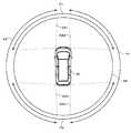
フロントモードM2は、前進時に必要となる車両9の前方や側方を主に示す画像を表示する動作モードである。例えば、図中に示すように、車両9の直上の仮想視点からみた車両9及び車両9の周辺の様子を示す合成画像(俯瞰画像)CPと、フロントカメラ51での撮影により得られる撮影画像PPとが同時にディスプレイ21に表示される。この合成画像CPの仮想視点の位置は、車両9の直上に限らず、ユーザの操作に応じて車両9の後方側などへ切り替えられるようになっていてもよい。 The front mode M2 is an operation mode for displaying an image mainly showing the front or side of the vehicle 9 that is required when the vehicle moves forward. For example, as shown in the figure, a composite image (overhead image) CP showing a state of the vehicle 9 and the surroundings of the vehicle 9 viewed from a virtual viewpoint directly above the vehicle 9, and a captured image PP obtained by capturing with the
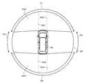
また、バックモードM3は、後退時に必要となる車両9の後方を主に示す画像を表示する動作モードである。例えば、図中に示すように、車両9の直上の仮想視点からみた車両9及び車両9の周辺の様子を示す合成画像(俯瞰画像)CPと、バックカメラ52での撮影により得られる撮影画像PPとが同時にディスプレイ21に表示される。この合成画像CPの仮想視点の位置は、車両9の直上に限らず、ユーザの操作に応じて車両9の前方側などへ切り替えられるようになっていてもよい。 Further, the back mode M3 is an operation mode for displaying an image mainly showing the rear of the vehicle 9 that is required when reversing. For example, as shown in the figure, a composite image (overhead image) CP showing a state of the vehicle 9 and the surroundings of the vehicle 9 viewed from a virtual viewpoint directly above the vehicle 9, and a captured image PP obtained by capturing with the
ナビモードM1において、ナビゲーション装置20の操作部22に所定の操作がなされると、フロントモードM2に切り替えられる。また、フロントモードM2において、ナビゲーション装置20の操作部22に所定の操作がなされると、ナビモードM1に切り替えられる。なお、ナビモードM1とフロントモードM2とは、車速度センサ82から入力される走行速度に応じて切り替えてもよい。 In the navigation mode M1, when a predetermined operation is performed on the operation unit 22 of the
また、ナビモードM1あるいはフロントモードM2の場合に、シフトセンサ81から入力されるシフトポジションが”R(後退)”となったときは、バックモードM3に切り替えられる。すなわち、シフトポジションが”R(後退)”の場合は、車両9は後退する状態であるため、車両9の後方を主に示すバックモードM3に切り替えられる。また、バックモードM3の場合に、シフトポジションが”R(後退)”以外となったときは、バックモードM3に切り替えられる直前の動作モードに戻ることになる。 In the navigation mode M1 or the front mode M2, when the shift position input from the
<1−3.合成画像の生成>
次に、画像生成部3の合成画像生成部32が、撮影部5で得られた複数の撮影画像に基づいて任意の仮想視点からみた車両9の周辺の様子を示す合成画像を生成する手法について説明する。合成画像を生成する際には、不揮発性メモリ40に予め記憶された車種別データ4aが利用される。図4は、合成画像を生成する手法を説明するための図である。<1-3. Generation of composite image>
Next, a method in which the composite
撮影部5の4つの車載カメラ51〜54で同時に撮影が行われると、フロントカメラ51で車両9の前方を示す撮影画像P1、バックカメラ52で車両9の後方を示す撮影画像P2、左サイドカメラ53で車両9の左側方を示す撮影画像P3、右サイドカメラ54で車両9の右側方を示す撮影画像P4がそれぞれ取得される。これら4つの撮影画像P1〜P4には、撮影時点の車両9の全周囲を示す情報が含まれていることになる。 When shooting is performed simultaneously with the four in-
次に、4つの撮影画像P1〜P4の各画素が、仮想的な三次元空間における立体曲面SPに投影される。立体曲面SPは、例えば略半球状(お椀形状)をしており、その中心部分(お椀の底部分)が車両9が存在する位置として定められている。撮影画像P1〜P4に含まれる各画素の位置と、この立体曲面SPの各画素の位置とは予め対応関係が定められている。このため、立体曲面SPの各画素の値は、この対応関係と撮影画像P1〜P4に含まれる各画素の値とに基づいて決定できる。 Next, each pixel of the four captured images P1 to P4 is projected onto a three-dimensional curved surface SP in a virtual three-dimensional space. The three-dimensional curved surface SP has, for example, a substantially hemispherical shape (a bowl shape), and a center portion (a bottom portion of the bowl) is determined as a position where the vehicle 9 exists. The correspondence between the positions of the pixels included in the captured images P1 to P4 and the positions of the pixels of the solid curved surface SP is determined in advance. For this reason, the value of each pixel of the solid curved surface SP can be determined based on this correspondence and the value of each pixel included in the captured images P1 to P4.
撮影画像P1〜P4の各画素の位置と立体曲面SPの各画素の位置との対応関係は、車両9における4つの車載カメラ51,52,53の配置(相互間距離、地上高さ、光軸角度等)に依存する。このため、この対応関係を示すテーブルデータが、不揮発性メモリ40に記憶された車種別データ4aに含まれている。 The correspondence between the positions of the pixels of the captured images P1 to P4 and the positions of the pixels of the three-dimensional curved surface SP is determined by the arrangement of the four in-
また、車種別データ4aに含まれる車体の形状やサイズを示すポリゴンデータが利用され、車両9の三次元形状を示すポリゴンモデルである車両像90が仮想的に構成される。構成された車両像90は、立体曲面SPが設定される三次元空間において、車両9の位置と定められた略半球状の中心部分に配置される。 Further, polygon data indicating the shape and size of the vehicle body included in the
さらに、立体曲面SPが存在する三次元空間に対して、制御部1の画像制御部11により仮想視点VPが設定される。仮想視点VPは、視点位置と視野方向とで規定され、この三次元空間における車両9の周辺に相当する任意の視点位置に任意の視野方向に向けて設定される。 Further, the virtual viewpoint VP is set by the
そして、設定された仮想視点VPに応じて、立体曲面SPにおける必要な領域が画像として切り出される。仮想視点VPと、立体曲面SPにおける必要な領域との関係は予め定められており、テーブルデータとして不揮発性メモリ40等に予め記憶されている。一方で、設定された仮想視点VPに応じてポリゴンで構成された車両像90に関してレンダリングがなされ、その結果となる二次元の車両像90が、切り出された画像に対して重畳される。これにより、任意の仮想視点からみた車両9及びその車両9の周辺の様子を示す合成画像が生成されることになる。 Then, according to the set virtual viewpoint VP, a necessary area on the three-dimensional curved surface SP is cut out as an image. The relationship between the virtual viewpoint VP and a necessary area in the three-dimensional curved surface SP is determined in advance, and is stored in advance in the
例えば、視点位置が車両9の位置の略中央の直上位置で、視野方向が略直下方向とした仮想視点VP1を設定した場合は、車両9の略直上から車両9を見下ろすように、車両9(実際には車両像90)及び車両9の周辺の様子を示す合成画像(俯瞰画像)CP1が生成される。また、図中に示すように、視点位置が車両9の位置の左後方で、視野方向が車両9における略前方とした仮想視点VP2を設定した場合は、車両9の左後方からその周辺全体を見渡すように、車両9(実際には車両像90)及び車両9の周辺の様子を示す合成画像CP2が生成される。 For example, when the virtual viewpoint VP1 in which the viewpoint position is a position just above the center of the position of the vehicle 9 and the visual field direction is a direction immediately below the vehicle 9 is set, the vehicle 9 ( Actually, a composite image (overhead image) CP1 showing the vehicle image 90) and the surroundings of the vehicle 9 is generated. Further, as shown in the figure, when the virtual viewpoint VP2 in which the viewpoint position is the left rear of the position of the vehicle 9 and the visual field direction is substantially in front of the vehicle 9 is set, the entire periphery from the left rear of the vehicle 9 is set. As seen, a composite image CP2 showing the vehicle 9 (actually the vehicle image 90) and the surroundings of the vehicle 9 is generated.
なお、実際に合成画像を生成する場合においては、立体曲面SPの全ての画素の値を決定する必要はなく、設定された仮想視点VPに対応して合成画像の生成に必要となる領域の画素の値のみを撮影画像P1〜P4に基づいて決定することで、処理速度を向上できる。 In the case of actually generating a composite image, it is not necessary to determine the values of all the pixels of the three-dimensional curved surface SP, and the pixels in the area necessary for generating the composite image corresponding to the set virtual viewpoint VP. The processing speed can be improved by determining only the value of? Based on the captured images P1 to P4.
前述のように、隣接して配置される2つの車載カメラにおいては重複して撮影可能な領域LA1〜LA2が存在する(図2参照。)。立体曲面SPにおいては、この重複して撮影可能な領域LA1〜LA2に対応する部分が存在する。当該部分については、2つの撮影画像と重複して対応付けられるため、以下「重複部分」という。合成画像は、立体曲面SPの一部を切り出して生成されることから、この立体曲面SPの重複部分は、合成画像の重複部分であるともいえる。 As described above, in two in-vehicle cameras arranged adjacent to each other, there are regions LA1 to LA2 that can be photographed in an overlapping manner (see FIG. 2). In the three-dimensional curved surface SP, there are portions corresponding to the overlapping areas LA1 to LA2 that can be photographed. Since this part is associated with two captured images in an overlapping manner, it is hereinafter referred to as “overlapping part”. Since the composite image is generated by cutting out a part of the solid curved surface SP, it can be said that the overlapping portion of the solid curved surface SP is an overlapping portion of the composite image.
図5は、立体曲面SPにおいて、4つの撮影画像P1〜P4がそれぞれ対応する範囲を示す図である。図5中においては、4つの撮影画像P1〜P4がそれぞれ対応する範囲を、当該撮影画像と同じ符号を付した矢印で示している。 FIG. 5 is a diagram showing ranges corresponding to the four captured images P1 to P4 in the three-dimensional curved surface SP. In FIG. 5, the ranges corresponding to the four captured images P1 to P4 are indicated by arrows with the same reference numerals as the captured images.
図5に示すように、立体曲面SPには4つの重複部分OA1〜OA4が存在している。具体的には、車両像90の前方左側の重複部分OA1は、車両9の前方左側の領域LA1に対応し、前方の撮影画像P1の範囲と左側方の撮影画像P3の範囲との双方に含まれている。また、車両像90の前方右側の重複部分OA2は、車両9の前方右側の領域LA2に対応し、前方の撮影画像P1の範囲と右側方の撮影画像P4の範囲との双方に含まれている。また、車両像90の後方左側の重複部分OA3は、車両9の後方左側の領域LA3に対応し、後方の撮影画像P2の範囲と左側方の撮影画像P3の範囲との双方に含まれている。また、車両像90の後方右側の重複部分OA4は、車両9の後方右側の領域LA4に対応し、後方の撮影画像P2の範囲と右側方の撮影画像P4の範囲との双方に含まれている。 As shown in FIG. 5, there are four overlapping portions OA1 to OA4 on the solid curved surface SP. Specifically, the overlap portion OA1 on the front left side of the
これらの立体曲面SPの重複部分OA1〜OA4の画素の値については、それぞれ対応する2つの撮影画像の画素の値を組み合わせて用いて導出される。なお、重複部分OA1〜OA4に関する画像の処理については左右対称としているため、以下の説明では左側の重複部分OA1,OA3を例に処理の内容を具体的に説明するが、右側の重複部分OA2,OA4に関しても左右反転して同様の処理がなされる。 The pixel values of the overlapping portions OA1 to OA4 of the three-dimensional curved surface SP are derived using a combination of pixel values of two corresponding captured images. Since the image processing related to the overlapping portions OA1 to OA4 is bilaterally symmetric, in the following description, the contents of the processing will be specifically described using the left overlapping portions OA1 and OA3 as an example. The same processing is performed with respect to OA4 by reversing left and right.
図6は、通常時において、立体曲面SPの重複部分OA1〜OA4の画素の値を導出する手法を説明する図である。図6中においては、4つの撮影画像P1〜P4がそれぞれ用いられる範囲を、当該撮影画像と同じ符号を付した矢印で示している。 FIG. 6 is a diagram for explaining a method for deriving the pixel values of the overlapping portions OA1 to OA4 of the solid curved surface SP in a normal state. In FIG. 6, the range in which the four captured images P1 to P4 are used is indicated by arrows with the same reference numerals as the captured images.
重複部分OA1においては、車両像90の左右方向に対して45°となる角度で車両像90の前方左角から伸ばした線分が基準線CL1とされる。そして、前方左角を基点として、基準線CL1から左回転方向に30°傾けた線分EL1の範囲まで前方の撮影画像P1が用いられる。一方で、基準線CL1から右回転方向に30°傾けた線分EL2の範囲まで左側方の撮影画像P3が用いられる。 In the overlapping portion OA1, a line segment extended from the front left corner of the
したがって、重複部分OA1のうち線分EL1より後側の領域NA1の画素の値については左側方の撮影画像P3のみが用いられ、線分EL2より右側の領域NA2の画素の値については前方の撮影画像P1のみが用いられる。そして、線分EL1と線分EL2とに挟まれた領域BA1の画素の値は、前方の撮影画像P1の画素の値と左側方の撮影画像P3の画素の値とを、同じ割合(0.5:0.5)でアルファブレンドして導出される。 Therefore, only the left side captured image P3 is used for the pixel value in the area NA1 on the rear side of the line segment EL1 in the overlapping portion OA1, and the front side image is captured for the pixel value in the area NA2 on the right side of the line segment EL2. Only the image P1 is used. The pixel value of the area BA1 sandwiched between the line segment EL1 and the line segment EL2 is equal to the pixel value of the front captured image P1 and the pixel value of the left captured image P3 (0. 5: 0.5) and is derived by alpha blending.
また、重複部分OA3においては、車両像90の左右方向に対して45°となる角度で車両像90の後方左角から伸ばした線分が基準線CL2とされる。そして、後方左角を基点として、基準線CL2から右回転方向に30°傾けた線分EL3の範囲まで後方の撮影画像P2が用いられる。一方で、基準線CL2から左回転方向に30°傾けた線分EL4の範囲まで左側方の撮影画像P3が用いられる。 In the overlapping portion OA3, a line segment extended from the rear left corner of the
したがって、重複部分OA3のうち線分EL3より前側の領域NA3の画素の値については左側方の撮影画像P3のみが用いられ、線分EL4より右側の領域NA4の画素の値については後方の撮影画像P2のみが用いられる。そして、線分EL3と線分EL4とに挟まれた領域BA2の画素の値は、後方の撮影画像P2の画素の値と左側方の撮影画像P3の画素の値とを、同じ割合(0.5:0.5)でアルファブレンドして導出される。 Therefore, only the left side captured image P3 is used for the pixel value in the area NA3 ahead of the line segment EL3 in the overlapping portion OA3, and the back captured image is used for the pixel value in the area NA4 on the right side of the line segment EL4. Only P2 is used. The pixel value of the area BA2 sandwiched between the line segment EL3 and the line segment EL4 is equal to the pixel value of the rear captured image P2 and the pixel value of the left captured image P3 (0. 5: 0.5) and is derived by alpha blending.
<1−4.灯火装置の点灯による不具合>
灯火装置が点灯すると、撮影画像P1〜P4の明るさが変化する。その結果、撮影画像P1〜P4を用いて生成される合成画像にも影響する。以下、灯火装置の点灯によって生じる合成画像への影響について説明する。<1-4. Troubles due to lighting equipment>
When the lighting device is turned on, the brightness of the captured images P1 to P4 changes. As a result, the composite image generated using the captured images P1 to P4 is also affected. Hereinafter, the influence on the composite image caused by lighting of the lighting device will be described.
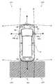
図7は、車両9のヘッドライト98が点灯している状態を示す図である。図中においてハッチングで示す領域HAが、ヘッドライト98により照明される領域を示している。図に示すように、2つの車載カメラで重複して撮影可能な前方の2つの領域LA1,LA2は、ヘッドライト98によって照明される。 FIG. 7 is a diagram illustrating a state where the
ここで、夜間など車両9の周辺環境が暗い場合に、ヘッドライト98が点灯された状態で、合成画像を生成する場合について想定する。 Here, it is assumed that a composite image is generated with the
フロントカメラ51の光軸51aは、ヘッドライト98が照明する領域に向けられている。このため、フロントカメラ51では、ヘッドライト98で照明された領域に存在する被写体の像が適正な明るさとなるように露出制御が実行される。ヘッドライト98によって領域LA1も照明されることから、フロントカメラ51で取得される撮影画像P1に含まれる領域LA1に存在する被写体の像は、適正な明るさとなる。 The
一方で、左サイドカメラ53の光軸53aは、ヘッドライト98の照明がなされていない車両9の左側に向けられている。このため、左サイドカメラ53では、照明の無い非常に暗い領域に存在する被写体の像が適正な明るさとなるように、撮影画像をできるだけ明るくする方向の露出制御が実行される。一方で、領域LA1についてはヘッドライト98によって明るく照明されることから、左サイドカメラ53で取得される撮影画像P3に含まれる領域LA1に存在する被写体の像は極端に明るくなりすぎ、白とびが生じる。 On the other hand, the
このような撮影画像P1及び撮影画像P3を含む撮影画像P1〜P4を用いて、仮に図6に示す手法で立体曲面SPの重複部分OA1の画素の値を導出したとする。この場合、重複部分OA1のうち線分EL2より右側の領域NA2では、前方の撮影画像P1のみが用いられるため、適切な明るさとなる。しかしながら、線分EL1より後側の領域NA1では、左側方の撮影画像P3のみが用いられるため、白とびが生じた状態となる。さらに、線分EL1と線分EL4とに挟まれた領域BA1では、極端に明るさの異なる撮影画像P1と撮影画像P3との画素の値がアルファブレンドされることになり、色滲みが発生してしまう。その結果、この重複部分OA1を含む合成画像では、この重複部分OA1に存在する被写体の像の視認性が大きく悪化してしまうことになる。このような現象は、重複部分OA2についても同様に生じる。 It is assumed that the pixel value of the overlapping portion OA1 of the three-dimensional curved surface SP is derived by using the captured images P1 to P4 including the captured image P1 and the captured image P3 as described above with the method illustrated in FIG. In this case, in the area NA2 on the right side of the line segment EL2 in the overlapping portion OA1, only the front captured image P1 is used, so that the brightness is appropriate. However, in the area NA1 on the rear side of the line segment EL1, since only the left-side captured image P3 is used, the overexposure occurs. Further, in the area BA1 sandwiched between the line segment EL1 and the line segment EL4, the pixel values of the photographed image P1 and the photographed image P3 having extremely different brightness are alpha-blended, and color blur occurs. End up. As a result, in the composite image including the overlapping portion OA1, the visibility of the subject image existing in the overlapping portion OA1 is greatly deteriorated. Such a phenomenon also occurs in the overlapping portion OA2.
図8は、車両9のブレーキランプ99が点灯している状態を示す図である。図中においてハッチングで示す領域RAが、ブレーキランプ99により照明される領域を示している。図に示すように、2つの車載カメラで重複して撮影可能な後方の2つの領域LA3,LA4は、ブレーキランプ99によって照明される。 FIG. 8 is a diagram illustrating a state where the
ここで、夜間など車両9の周辺環境が暗い場合に、ブレーキランプ99が点灯された状態で、合成画像を生成する場合について想定する。 Here, it is assumed that a composite image is generated with the
バックカメラ52の光軸52aは、ブレーキランプ99が照明する領域に向けられている。このため、バックカメラ52では、ブレーキランプ99で照明された領域に存在する被写体の像が適正な明るさとなるように露出制御が実行される。ブレーキランプ99によって領域LA3も照明されることから、バックカメラ52で取得される撮影画像P2に含まれる領域LA3に存在する被写体の像は、適正な明るさとなる。 The
一方で、左サイドカメラ53の光軸53aは、ブレーキランプ99の照明がなされていない車両9の左側に向けられている。このため、左サイドカメラ53では、照明の無い非常に暗い領域に存在する被写体の像が適正な明るさとなるように、撮影画像をできるだけ明るくする方向の露出制御が実行される。一方で、領域LA3についてはブレーキランプ99によって明るく照明されることから、左サイドカメラ53で取得される撮影画像P3に含まれる領域LA3に存在する被写体の像は極端に明るくなりすぎ、白とびが生じる。 On the other hand, the
このような撮影画像P2及び撮影画像P3を含む撮影画像P1〜P4を用いて、仮に図6に示す手法で立体曲面SPの重複部分OA3の画素の値を導出したとする。この場合、重複部分OA3のうち線分EL4より右側の領域NA4では、後方の撮影画像P2のみが用いられるため、適切な明るさとなる。しかしながら、線分EL3より前側の領域NA3では、左側方の撮影画像P3のみが用いられるため、白とびが生じた状態となる。さらに、線分EL3と線分EL4とに挟まれた領域BA2では、極端に明るさの異なる撮影画像P2と撮影画像P3との画素の値がアルファブレンドされることになり、色滲みが発生してしまう。その結果、この重複部分OA3を含む合成画像では、この重複部分OA3に存在する被写体の像の視認性が大きく悪化してしまうことになる。このような現象は、重複部分OA4についても同様に生じる。 It is assumed that the pixel value of the overlapping portion OA3 of the three-dimensional curved surface SP is derived by using the captured images P1 to P4 including the captured image P2 and the captured image P3 as described above with the method illustrated in FIG. In this case, in the area NA4 on the right side of the line segment EL4 in the overlapping portion OA3, only the rear captured image P2 is used, so that the brightness is appropriate. However, in the area NA3 on the front side of the line segment EL3, since only the left-side photographed image P3 is used, a whiteout occurs. Furthermore, in the area BA2 sandwiched between the line segment EL3 and the line segment EL4, the pixel values of the captured image P2 and the captured image P3 having extremely different brightness are alpha-blended, and color blurring occurs. End up. As a result, in the composite image including the overlapping portion OA3, the visibility of the subject image existing in the overlapping portion OA3 is greatly deteriorated. Such a phenomenon also occurs in the overlapping portion OA4.
<1−5.不具合の低減>
本実施の形態の画像表示システム120では、灯火装置が非点灯の場合は、図6に示す手法で立体曲面SPの重複部分OA1〜OA4の画素の値を導出する。しかしながら、灯火装置が点灯した場合は、点灯によって生じる上述した合成画像の不具合を低減するため、図6に示すものとは一部が異なる手法で立体曲面SPの重複部分OA1〜OA4の画素の値を導出するようにしている。<1-5. Reduction of defects>
In the
図9は、ヘッドライト98の点灯時において採用される立体曲面SPの重複部分OA1〜OA4の画素の値を導出する手法を説明する図である。図9中においても、4つの撮影画像P1〜P4がそれぞれ用いられる範囲を、当該撮影画像と同じ符号を付した矢印で示している。 FIG. 9 is a diagram for explaining a method for deriving the pixel values of the overlapping portions OA1 to OA4 of the three-dimensional curved surface SP employed when the
図9に示す手法では、図6に示す手法と比較して、適正な明るさの撮影画像P1を用いる範囲を最大限に広げる一方で、白とびが生じている撮影画像P3を用いる範囲を狭くしている。換言すれば、ヘッドライト98が照明する領域に光軸が向けられたフロントカメラ51の撮影画像P1のデータ量を増加させ、ヘッドライト98が照明する領域に光軸が向けられていない左サイドカメラ53の撮影画像P3のデータ量を減少させているともいえる。 In the method shown in FIG. 9, compared with the method shown in FIG. 6, the range using the photographed image P1 with appropriate brightness is expanded to the maximum, while the range using the photographed image P3 in which overexposure occurs is narrowed. doing. In other words, the data amount of the captured image P1 of the
具体的には、重複部分OA1においては、車両像90の左右方向に対して25°となる角度で車両像90の前方左角から伸ばした線分が基準線CL1とされる。そして、前方左角を基点として、基準線CL1から左回転方向に30°傾けた線分EL1の範囲まで前方の撮影画像P1が用いられる。一方で、基準線CL1から右回転方向に30°傾けた線分EL2の範囲まで左側方の撮影画像P3が用いられる。 Specifically, in the overlapping portion OA1, a line segment extended from the front left corner of the
これにより、図6に示す手法と比較して、線分EL1と線分EL2とに挟まれた領域BA1が左回転方向に移動される。これにより、前方の撮影画像P1のみが用いられる領域NA2が増加され、左側方の撮影画像P3のみが用いられる領域NA1が無くなる。したがって、重複部分OA1において、適正な明るさの領域を広げることができるとともに、白とびが生じる領域を解消できる。その結果、重複部分OA1を含む合成画像では、この重複部分OA1に存在する被写体の像の視認性を向上できることになる。なお、図9に示す手法では、車両像90の後方の重複部分OA3,OA4については、図6に示す手法と同様の手法となっている。 As a result, as compared with the method shown in FIG. 6, the area BA1 sandwiched between the line segment EL1 and the line segment EL2 is moved in the counterclockwise direction. As a result, the area NA2 in which only the front captured image P1 is used is increased, and the area NA1 in which only the left captured image P3 is used is eliminated. Therefore, in the overlapping portion OA1, it is possible to widen an area with appropriate brightness and to eliminate an area where overexposure occurs. As a result, in the composite image including the overlapping portion OA1, the visibility of the subject image existing in the overlapping portion OA1 can be improved. In the method shown in FIG. 9, the overlapping portions OA3 and OA4 behind the
図10は、ブレーキランプ99の点灯時において採用される立体曲面SPの重複部分OA1〜OA4の画素の値を導出する手法を説明する図である。図10中においても、4つの撮影画像P1〜P4がそれぞれ用いられる範囲を、当該撮影画像と同じ符号を付した矢印で示している。 FIG. 10 is a diagram illustrating a method for deriving the pixel values of the overlapping portions OA1 to OA4 of the three-dimensional curved surface SP employed when the
図10に示す手法では、図6に示す手法と比較して、適正な明るさの撮影画像P2を用いる範囲を最大限に広げる一方で、白とびが生じている撮影画像P3を用いる範囲を狭くしている。換言すれば、ブレーキランプ99が照明する領域に光軸が向けられたバックカメラ52の撮影画像P2のデータ量を増加させ、ブレーキランプ99が照明する領域に光軸が向けられていない左サイドカメラ53の撮影画像P3のデータ量を減少させているともいえる。 In the method illustrated in FIG. 10, as compared with the method illustrated in FIG. 6, the range in which the captured image P <b> 2 having appropriate brightness is expanded to the maximum, while the range in which the captured image P <b> 3 in which the overexposure occurs is narrowed. doing. In other words, the left side camera in which the data amount of the captured image P2 of the
具体的には、重複部分OA3においては、車両像90の左右方向に対して25°となる角度で車両像90の後方左角から伸ばした線分が基準線CL2とされる。そして、後方左角を基点として、基準線CL2から右回転方向に30°傾けた線分EL3の範囲まで後方の撮影画像P2が用いられる。一方で、基準線CL1から左回転方向に30°傾けた線分EL4の範囲まで左側方の撮影画像P3が用いられる。 Specifically, in the overlapping portion OA3, a line segment extended from the rear left corner of the
これにより、図6に示す手法と比較して、線分EL3と線分EL4とに挟まれた領域BA2が右回転方向に移動される。これにより、後方の撮影画像P2のみが用いられる領域NA4が増加され、左側方の撮影画像P3のみが用いられる領域NA3が無くなる。したがって、重複部分OA3において、適正な明るさの領域を広げることができるとともに、白とびが生じる領域を解消できる。その結果、重複部分OA3を含む合成画像では、この重複部分OA3に存在する被写体の像の視認性を向上できることになる。なお、図10に示す手法では、車両像90の前方の重複部分OA1,OA2については、図6に示す手法と同様の手法となっている。 Thereby, compared with the method shown in FIG. 6, the area BA2 sandwiched between the line segment EL3 and the line segment EL4 is moved in the clockwise direction. As a result, the area NA4 in which only the rear captured image P2 is used is increased, and the area NA3 in which only the left captured image P3 is used is eliminated. Therefore, in the overlapping portion OA3, it is possible to widen an area of appropriate brightness and eliminate an area where overexposure occurs. As a result, in the composite image including the overlapping portion OA3, the visibility of the subject image existing in the overlapping portion OA3 can be improved. In the method shown in FIG. 10, the overlapping portions OA1 and OA2 in front of the
また、ヘッドライト98及びブレーキランプ99の双方が点灯している場合は、図11に示すように、車両像90の前方の重複部分OA1,OA2については図9に示す手法を採用し、車両像90の後方の重複部分OA3,OA4については図10に示す手法を採用すればよい。 Further, when both the
<1−6.処理フロー>
次に、画像表示システム120が灯火装置の点灯状態に応じて、重複部分OA1〜OA4の画素の値を導出する手法を変更する処理の流れについて説明する。図12は、画像表示システム120が合成画像を表示させる処理の流れを示す図である。この処理は、制御部1の制御によって繰り返し実行されるものである。<1-6. Processing flow>
Next, a flow of processing in which the
まず、ディスプレイ21に車両9の周辺の様子を示す合成画像を表示させる状態であるかが判定される(ステップS11)。具体的には、動作モードが、フロントモードM2またはバックモードM3であるかが判定される。動作モードが、ナビモードM1の場合は(ステップS11にてNo)、合成画像を表示させないためそのまま処理が終了する。 First, it is determined whether the
動作モードが、フロントモードM2またはバックモードM3の場合は(ステップS11にてYes)、次に、ヘッドライト98が点灯されているか否かが判定される(ステップS12)。ヘッドライト98の点灯状態は、灯火制御装置84からの信号に基づいて判断される。ヘッドライト98が点灯していない場合は(ステップS12にてNo)、処理はステップS14に進む。 If the operation mode is the front mode M2 or the back mode M3 (Yes in step S11), it is next determined whether or not the
一方、ヘッドライト98が点灯している場合は、立体曲面SPにおける車両像90の前方の重複部分OA1,OA2に係る画素の値の導出手法が、図6に示す手法から図9に示す手法に画像制御部11により変更される。すなわち、ヘッドライト98の非点灯時と比較して、重複部分OA1,OA2に用いる、フロントカメラ51の撮影画像P1のデータ量が増加される一方で、左サイドカメラ53の撮影画像P3のデータ量が減少されることになる(ステップS13)。 On the other hand, when the
次に、ブレーキランプ99が点灯されているか否かが判定される(ステップS14)。ブレーキランプ99の点灯状態は、灯火制御装置84からの信号に基づいて判断される。ブレーキランプ99が点灯していない場合は(ステップS14にてNo)、処理はステップS16に進む。 Next, it is determined whether or not the
一方、ブレーキランプ99が点灯している場合は、立体曲面SPにおける車両像90の後方の重複部分OA3,OA4に係る画素の値の導出手法が、図6に示す手法から図10に示す手法に画像制御部11により変更される。すなわち、ブレーキランプ99の非点灯時と比較して、重複部分OA3,OA4に用いる、バックカメラ52の撮影画像P2のデータ量が増加され、左サイドカメラ53の撮影画像P3のデータ量が減少されることになる(ステップS15)。 On the other hand, when the
次に、灯火装置の点灯状態に応じて変更された手法により、立体曲面SPの各画素の値が導出され、合成画像が生成される(ステップS16)。そして、生成された合成画像がディスプレイ21に表示される(ステップS17)。 Next, the value of each pixel of the three-dimensional curved surface SP is derived by a method changed according to the lighting state of the lighting device, and a composite image is generated (step S16). Then, the generated composite image is displayed on the display 21 (step S17).
以上のように、本実施の形態の画像表示システム120では、複数の車載カメラのうちの2つの車載カメラで重複して撮影可能な車両9の周辺の領域に対応する合成画像の重複部分に用いる撮影画像のデータ量を、ヘッドライト98及びブレーキランプ99の点灯状態に応じて変更する。このため、ヘッドライト98及びブレーキランプ99の点灯に起因して合成画像の重複部分に生じる不具合を低減できる。 As described above, in the
また、灯火装置が照明する領域に光軸が向けられた適切な明るさの車載カメラの撮影画像のデータ量を増加させ、灯火装置が照明する領域に光軸が向けられていない車載カメラの撮影画像のデータ量を減少させるため、合成画像の重複部分に生じる不具合を有効に低減できる。 In addition, the amount of captured image data of an in-vehicle camera with an appropriate brightness whose optical axis is directed to the area illuminated by the lighting device is increased, and the imaging of the in-vehicle camera whose optical axis is not directed to the area illuminated by the lighting device Since the amount of image data is reduced, it is possible to effectively reduce defects that occur in overlapping portions of the composite image.
また、灯火装置が照明する領域に光軸が向けられた適切な明るさの車載カメラの撮影画像を用いる範囲を増加させ、灯火装置が照明する領域に光軸が向けられていない車載カメラの撮影画像を用いる範囲を減少させるため、合成画像の重複部分に生じる不具合を有効に低減できる。 In addition, the range of using the captured image of the vehicle camera with an appropriate brightness whose optical axis is directed to the area illuminated by the lighting device is increased, and the imaging of the vehicle camera whose optical axis is not directed to the area illuminated by the lighting device Since the range in which the image is used is reduced, it is possible to effectively reduce defects that occur in the overlapping portion of the composite image.
<2.第2の実施の形態>
次に、第2の実施の形態について説明する。第2の実施の形態における画像表示システムの構成・処理は、第1の実施の形態とほぼ同様であるが一部のみが相違しているため、以下、第1の実施の形態との相違点を中心に説明する。第2の実施の形態では、灯火装置が点灯している場合は、灯火装置が非点灯の場合よりも、撮影画像をアルファブレンドする領域を狭くするようにしている。<2. Second Embodiment>
Next, a second embodiment will be described. The configuration and processing of the image display system in the second embodiment are substantially the same as those in the first embodiment, but only a part thereof is different. Therefore, the differences from the first embodiment are described below. The explanation will be focused on. In the second embodiment, when the lighting device is lit, the region where the shot image is alpha blended is made narrower than when the lighting device is not lit.
図13は、第2の実施の形態における、灯火装置が点灯中の場合の立体曲面SPの重複部分OA1〜OA4の画素の値を導出する手法を説明する図である。図13中においても、4つの撮影画像P1〜P4がそれぞれ用いられる範囲を、当該撮影画像と同じ符号を付した矢印で示している。なお、図13は、ヘッドライト98及びブレーキランプ99の双方が点灯している場合を例示しているが、ヘッドライト98のみが点灯している場合は車両像90の前方の重複部分OA1,OA2のみに当該手法を採用し、ブレーキランプ99のみが点灯している場合は車両像90の後方の重複部分OA3,OA4のみに当該手法を採用すればよい。 FIG. 13 is a diagram for explaining a method of deriving the pixel values of the overlapping portions OA1 to OA4 of the three-dimensional curved surface SP when the lighting device is turned on in the second embodiment. Also in FIG. 13, ranges in which the four captured images P <b> 1 to P <b> 4 are used are indicated by arrows with the same reference numerals as the captured images. FIG. 13 illustrates the case where both the
重複部分OA1においては、車両像90の左右方向に対して10°となる角度で車両像90の前方左角から伸ばした線分が基準線CL1とされる。そして、前方左角を基点として、基準線CL1から左回転方向に15°傾けた線分EL1の範囲まで前方の撮影画像P1が用いられる。一方で、基準線CL1から右回転方向に15°傾けた線分EL2の範囲まで左側方の撮影画像P3が用いられる。 In the overlapping portion OA1, a line segment extended from the front left corner of the
これにより、図9に示す手法と比較して、線分EL1と線分EL2とに挟まれた撮影画像P1,P3をアルファブレンドする領域BA1が狭くなり、前方の撮影画像P1のみが用いられる領域NA2がさらに増加される。したがって、重複部分OA1において、適正な明るさの領域を広げることができるとともに、色滲みが生じる領域を減少させることができる。 As a result, as compared with the method shown in FIG. 9, the area BA1 for alpha blending the captured images P1 and P3 sandwiched between the line segment EL1 and the line segment EL2 is narrowed, and only the front captured image P1 is used. NA2 is further increased. Therefore, in the overlapping portion OA1, it is possible to widen an area with appropriate brightness and reduce an area where color blur occurs.
また、重複部分OA3においても、車両像90の左右方向に対して10°となる角度で車両像90の後方左角から伸ばした線分が基準線CL2とされる。そして、後方左角を基点として、基準線CL2から右回転方向に15°傾けた線分EL3の範囲まで後方の撮影画像P2が用いられる。一方で、基準線CL2から左回転方向に15°傾けた線分EL4の範囲まで左側方の撮影画像P3が用いられる。 Also in the overlapping portion OA3, a line segment extended from the rear left corner of the
これにより、図10に示す手法と比較して、線分EL3と線分EL4とに挟まれた撮影画像P2,P3をアルファブレンドする領域BA2が狭くなり、後方の撮影画像P2のみが用いられる領域NA4がさらに増加される。したがって、重複部分OA3において、適正な明るさの領域を広げることができるとともに、色滲みが生じる領域を減少させることができる。 As a result, as compared with the method shown in FIG. 10, the area BA2 for alpha blending the captured images P2 and P3 sandwiched between the line segment EL3 and the line segment EL4 is narrowed, and only the rear captured image P2 is used. NA4 is further increased. Therefore, in the overlapping portion OA3, it is possible to widen an area with appropriate brightness and reduce an area where color blur occurs.
<3.第3の実施の形態>
次に、第3の実施の形態について説明する。第3の実施の形態における画像表示システムの構成・処理は、第1の実施の形態とほぼ同様であるが一部のみが相違しているため、以下、第1の実施の形態との相違点を中心に説明する。第3の実施の形態では、灯火装置が点灯している場合は、灯火装置が照明する領域に光軸が向けられた適切な明るさの車載カメラの撮影画像のみを重複部分に用いるようにしている。<3. Third Embodiment>
Next, a third embodiment will be described. The configuration and processing of the image display system according to the third embodiment are substantially the same as those of the first embodiment, but only a part thereof is different. Therefore, the differences from the first embodiment are described below. The explanation will be focused on. In the third embodiment, when the lighting device is lit, only the captured image of the vehicle camera with the appropriate brightness with the optical axis directed to the area illuminated by the lighting device is used for the overlapping portion. Yes.
図14は、第3の実施の形態における、灯火装置が点灯中の場合の立体曲面SPの重複部分OA1〜OA4の画素の値を導出する手法を説明する図である。図14中においても、4つの撮影画像P1〜P4がそれぞれ用いられる範囲を、当該撮影画像と同じ符号を付した矢印で示している。なお、図14は、ヘッドライト98及びブレーキランプ99の双方が点灯している場合を例示しているが、ヘッドライト98のみが点灯している場合は車両像90の前方の重複部分OA1,OA2のみに当該手法を採用し、ブレーキランプ99のみが点灯している場合は車両像90の後方の重複部分OA3,OA4のみに当該手法を採用すればよい。 FIG. 14 is a diagram for explaining a method of deriving the pixel values of the overlapping portions OA1 to OA4 of the three-dimensional curved surface SP when the lighting device is lit in the third embodiment. Also in FIG. 14, the range in which each of the four captured images P1 to P4 is used is indicated by an arrow with the same reference numeral as that of the captured image. FIG. 14 illustrates the case where both the
重複部分OA1においては、撮影画像P1,P3をアルファブレンドする領域BA1が無くなり、前方の撮影画像P1のみが用いられる領域NA2のみとなっている。したがって、重複部分OA1において、左側方の撮影画像P3については一切用いられていない。これにより、重複部分OA1において、適正な明るさの領域のみとすることができるとともに、白とびや色滲みを解消することができる。 In the overlapping portion OA1, there is no area BA1 in which the captured images P1, P3 are alpha blended, and only the area NA2 in which only the front captured image P1 is used. Therefore, the left-side captured image P3 is not used at all in the overlapping portion OA1. Thereby, in the overlapping portion OA1, only an area with appropriate brightness can be obtained, and overexposure and color blur can be eliminated.
重複部分OA3においても、撮影画像P2,P3をアルファブレンドする領域BA2が無くなり、後方の撮影画像P2のみが用いられる領域NA4のみとなっている。したがって、重複部分OA3において、左側方の撮影画像P3については一切用いられていない。これにより、重複部分OA3において、適正な明るさの領域のみとすることができるとともに、白とびや色滲みを解消することができる。 Even in the overlapping portion OA3, the area BA2 in which the captured images P2 and P3 are alpha blended is eliminated, and only the area NA4 in which only the rear captured image P2 is used. Accordingly, the left-side captured image P3 is not used at all in the overlapping portion OA3. As a result, in the overlapping portion OA3, it is possible to make only an area with appropriate brightness, and it is possible to eliminate overexposure and color blur.
<4.変形例>
以上、本発明の実施の形態について説明してきたが、この発明は上記実施の形態に限定されるものではなく様々な変形が可能である。以下では、このような変形例について説明する。上記実施の形態で説明した形態及び以下で説明する形態を含む全ての形態は、適宜に組み合わせ可能である。<4. Modification>
Although the embodiments of the present invention have been described above, the present invention is not limited to the above-described embodiments, and various modifications are possible. Below, such a modification is demonstrated. All forms including those described in the above embodiment and those described below can be combined as appropriate.
上記実施の形態において、アルファブレンドする領域BA1,BA2におけるブレンドの割合は、灯火装置が照明する領域に光軸が向けられた車載カメラの撮影画像と、灯火装置が照明する領域に光軸が向けられていない車載カメラの撮影画像とで同じ割合としていた。これに対して、灯火装置が点灯中の場合は灯火装置が非点灯の場合よりも、灯火装置が照明する領域に光軸が向けられた車載カメラの撮影画像のブレンドの割合を高くしてもよい。例えば、灯火装置が照明する領域に光軸が向けられた車載カメラの撮影画像と、灯火装置が照明する領域に光軸が向けられていない車載カメラの撮影画像との割合を、0.7:0.3とすることが考えられる。このようにしても、灯火装置が照明する領域に光軸が向けられた適切な明るさの車載カメラの撮影画像のデータ量を増加させ、灯火装置が照明する領域に光軸が向けられていない車載カメラの撮影画像のデータ量を減少させることができる。その結果、アルファブレンドする領域BA1,BA2に生じる色滲みを有効に低減できる。また、このブレンドの割合を変更する手法を採用する場合、アルファブレンドする領域BA1,BA2の位置は図6のままとしてもよいが、図9〜図11,図13で説明した手法にブレンドの割合を変更する手法を組み合わせてもよい。 In the above embodiment, the blend ratio in the areas BA1 and BA2 to be alpha-blended is based on the shot image of the in-vehicle camera in which the optical axis is directed to the area illuminated by the lighting device and the optical axis directed to the area illuminated by the lighting device. The ratio was the same for the images taken by the in-vehicle cameras that were not used. On the other hand, when the lighting device is lit, even if the blending ratio of the captured image of the in-vehicle camera in which the optical axis is directed to the area illuminated by the lighting device is higher than when the lighting device is not lit. Good. For example, the ratio of the captured image of the in-vehicle camera in which the optical axis is directed to the area illuminated by the lighting device and the captured image of the in-vehicle camera in which the optical axis is not directed to the area illuminated by the lighting device is 0.7: It can be considered to be 0.3. Even if it does in this way, the data amount of the picked-up image of the vehicle-mounted camera of the appropriate brightness in which the optical axis was directed to the area | region which a lighting apparatus illuminates increases, and the optical axis is not directed to the area | region which a lighting apparatus illuminates It is possible to reduce the data amount of the captured image of the in-vehicle camera. As a result, it is possible to effectively reduce the color blur that occurs in the areas BA1 and BA2 to be alpha blended. Further, when the method of changing the blend ratio is adopted, the positions of the alpha-blending areas BA1 and BA2 may remain as in FIG. 6, but the blend ratio in the techniques described in FIGS. 9 to 11 and FIG. You may combine the method of changing.
また、上記第2の実施の形態では、灯火装置が点灯中の場合は、灯火装置が非点灯の場合と比較して、基準線CL1,CL2を移動させた上で、アルファブレンドする領域BA1,BA2を狭くするようにしていた。これに対して、基準線CL1,CL2は移動させずにアルファブレンドする領域BA1,BA2を狭くするようにしてもよい。これによっても、アルファブレンドする領域BA1,BA2に生じる色滲みを有効に低減できる。 In the second embodiment, when the lighting device is lit, the reference lines CL1 and CL2 are moved and then the alpha blend region BA1, compared to the case where the lighting device is not lit. BA2 was made narrower. On the other hand, the reference lines CL1 and CL2 may not be moved and the alpha blended areas BA1 and BA2 may be narrowed. This can also effectively reduce the color blur that occurs in the alpha-blended areas BA1 and BA2.
また、上記実施の形態では、ヘッドライト98及びブレーキランプ99の点灯に関してのみ考慮して処理を行っていたが、ヘッドライト98及びブレーキランプ99以外の車両9が備える灯火装置の点灯状態を考慮するようにしてもよい。 Moreover, in the said embodiment, although it processed only considering about lighting of the
また、上記実施の形態では、画像生成装置100とナビゲーション装置20とは別の装置であるとして説明したが、画像生成装置100とナビゲーション装置20とが同一の筐体内に配置されて一体型の装置として構成されてもよい。 In the above-described embodiment, the
また、上記実施の形態では、画像生成装置100で生成された画像を表示する表示装置はナビゲーション装置20であるとして説明したが、ナビゲーション機能等の特殊な機能を有していない一般的な表示装置であってもよい。 In the above embodiment, the display device that displays the image generated by the
また、上記実施の形態において、画像生成装置100の制御部1によって実現されると説明した機能の一部は、ナビゲーション装置20の制御部23によって実現されてもよい。 In the above embodiment, some of the functions described as being realized by the
また、上記実施の形態において、信号入力部41を介して画像生成装置100の制御部1に入力されると説明した信号の一部または全部は、ナビゲーション装置20に入力されるようになっていてもよい。この場合は、ナビ通信部42を経由して、画像生成装置100の制御部1に当該信号を入力すればよい。 In the above embodiment, part or all of the signals described as being input to the
また、上記実施の形態では、プログラムに従ったCPUの演算処理によってソフトウェア的に各種の機能が実現されると説明したが、これら機能のうちの一部は電気的なハードウェア回路により実現されてもよい。また逆に、ハードウェア回路によって実現されるとした機能のうちの一部は、ソフトウェア的に実現されてもよい。 Further, in the above-described embodiment, it has been described that various functions are realized in software by the arithmetic processing of the CPU according to the program. However, some of these functions are realized by an electrical hardware circuit. Also good. Conversely, some of the functions realized by the hardware circuit may be realized by software.
1 制御部
11 画像制御部
32 合成画像生成部
51 フロントカメラ
52 バックカメラ
53 左サイドカメラ
54 右サイドカメラ
84 灯火制御装置
98 ヘッドライト
99 ブレーキランプDESCRIPTION OF
Claims (6)
Translated fromJapanese前記車両の異なる位置に配置された複数の車載カメラの複数の撮影画像を合成して、仮想視点から見た前記車両の周辺の様子を示す合成画像を生成する生成手段と、
前記車両が備える灯火装置の点灯状態を示す信号を入力する入力手段と、
前記複数の車載カメラのうちの2つの車載カメラで重複して撮影可能な前記車両の周辺の領域に対応する前記合成画像の重複部分に用いる前記2つの車載カメラの2つの撮影画像のデータ量を、前記点灯状態に応じて変更する変更手段と、
を備え、
前記生成手段は、前記合成画像の重複部分の少なくとも一部を前記2つの車載カメラの2つの撮影画像をブレンドして生成し、
前記変更手段は、
前記灯火装置が点灯中の場合は、前記灯火装置が非点灯の場合よりも、
前記2つの車載カメラのうち、点灯中の前記灯火装置が照明する領域に光軸が向けられた第1車載カメラの撮影画像のデータ量を増加させ、他方の第2車載カメラの撮影画像のデータ量を減少させることを特徴とする画像生成装置。An image generation device that generates an image to be displayed on a display device mounted on a vehicle,
Generating means for synthesizing a plurality of captured images of a plurality of in-vehicle cameras arranged at different positions of the vehicle and generating a synthesized image showing a state of the periphery of the vehicle viewed from a virtual viewpoint;
Input means for inputting a signal indicating a lighting state of a lighting device provided in the vehicle;
The amount of data of two captured images of the two in-vehicle cameras used for the overlapping portion of the composite image corresponding to a region around the vehicle that can be captured by two in-vehicle cameras out of the plurality of in-vehicle cameras. Changing means for changing according to the lighting state;
Equipped witha,
The generation means generates at least a part of the overlapping portion of the composite image by blending two captured images of the two in-vehicle cameras,
The changing means is
When the lighting device is lit, than when the lighting device is not lit,
Of the two in-vehicle cameras, the data amount of the captured image of the first in-vehicle camera is increased by increasing the data amount of the first in-vehicle camera whose optical axis is directed to the area illuminated by the lighting device that is lit. An image generating apparatus characterizedby reducing the amount .
前記変更手段は、
前記灯火装置が点灯中の場合は、前記灯火装置が非点灯の場合よりも、
前記合成画像の重複部分における、前記第1車載カメラの撮影画像を用いる範囲を広げ、前記第2車載カメラの撮影画像を用いる範囲を狭くすることを特徴とする画像生成装置。The image generation apparatus according to claim 1,
The changing means is
When the lighting device is lit, than when the lighting device is not lit,
An image generation apparatus characterizedin that,in an overlapping portion of the composite image, a range in which a captured image of the first in-vehicle camera is used is widened and a range in which a captured image of the second in-vehicle camera is used is narrowed .
前記変更手段は、
前記灯火装置が点灯中の場合は、前記灯火装置が非点灯の場合よりも、
前記第1車載カメラの撮影画像と前記第2車載カメラの撮影画像とをブレンドする領域を狭くすることを特徴とする画像生成装置。The image generation apparatus according to claim1 or 2 ,
The changing means is
When the lighting device is lit, than when the lighting device is not lit,
An image generating apparatus characterizedby narrowing a region where a photographed image of the first vehicle-mounted camera and a photographed image of the second vehicle-mounted camera are blended .
前記変更手段は、
前記灯火装置が点灯中の場合は、前記灯火装置が非点灯の場合よりも、
前記第1車載カメラの撮影画像と前記第2車載カメラの撮影画像とをブレンドする領域における、前記第1車載カメラの撮影画像のブレンドの割合を高くすることを特徴とする画像生成装置。In the image generation device according toany one of claims1 to 3 ,
The changing means is
When the lighting device is lit, than when the lighting device is not lit,
An image generating apparatus characterizedin thata ratio of blending of images captured by the first vehicle-mounted camera is increased in a region where the images captured by the first vehicle-mounted camera and the images captured by the second vehicle-mounted camera are blended.
請求項1ないし4のいずれかに記載の画像生成装置と、An image generation apparatus according to any one of claims 1 to 4,
前記画像生成装置で生成された画像を表示する表示装置と、A display device for displaying an image generated by the image generation device;
を備えることを特徴とする画像表示システム。An image display system comprising:
(a)前記車両の異なる位置に配置された複数の車載カメラの複数の撮影画像を合成して、仮想視点から見た前記車両の周辺の様子を示す合成画像を生成する工程と、(A) synthesizing a plurality of captured images of a plurality of in-vehicle cameras arranged at different positions of the vehicle, and generating a synthesized image showing a state around the vehicle viewed from a virtual viewpoint;
(b)前記車両が備える灯火装置の点灯状態を示す信号を入力する工程と、(B) inputting a signal indicating a lighting state of a lighting device provided in the vehicle;
(c)前記複数の車載カメラのうちの2つの車載カメラで重複して撮影可能な前記車両の周辺の領域に対応する前記合成画像の重複部分に用いる前記2つの車載カメラの2つの撮影画像のデータ量を、前記点灯状態に応じて変更する工程と、(C) The two captured images of the two in-vehicle cameras used for the overlapping portion of the composite image corresponding to the area around the vehicle that can be captured by two in-vehicle cameras out of the plurality of in-vehicle cameras. Changing the amount of data according to the lighting state;
を備え、With
前記工程(a)は、前記合成画像の重複部分の少なくとも一部を前記2つの車載カメラの2つの撮影画像をブレンドして生成し、In the step (a), at least a part of the overlapping portion of the composite image is generated by blending two captured images of the two in-vehicle cameras,
前記工程(c)は、The step (c)
前記灯火装置が点灯中の場合は、前記灯火装置が非点灯の場合よりも、When the lighting device is lit, than when the lighting device is not lit,
前記2つの車載カメラのうち、点灯中の前記灯火装置が照明する領域に光軸が向けられた第1車載カメラの撮影画像のデータ量を増加させ、他方の第2車載カメラの撮影画像のデータ量を減少させることを特徴とする画像生成方法。Of the two in-vehicle cameras, the data amount of the captured image of the first in-vehicle camera is increased by increasing the data amount of the first in-vehicle camera whose optical axis is directed to the area illuminated by the lighting device that is lit. An image generation method characterized by reducing the amount.
Priority Applications (3)
| Application Number | Priority Date | Filing Date | Title |
|---|---|---|---|
| JP2010070312AJP5548002B2 (en) | 2010-03-25 | 2010-03-25 | Image generation apparatus, image display system, and image generation method |
| CN2011100381283ACN102202214B (en) | 2010-03-25 | 2011-02-12 | Image generation apparatus, image display system and image generation method |
| US13/032,946US8780202B2 (en) | 2010-03-25 | 2011-02-23 | Image generation apparatus |
Applications Claiming Priority (1)
| Application Number | Priority Date | Filing Date | Title |
|---|---|---|---|
| JP2010070312AJP5548002B2 (en) | 2010-03-25 | 2010-03-25 | Image generation apparatus, image display system, and image generation method |
Publications (2)
| Publication Number | Publication Date |
|---|---|
| JP2011205375A JP2011205375A (en) | 2011-10-13 |
| JP5548002B2true JP5548002B2 (en) | 2014-07-16 |
Family
ID=44655991
Family Applications (1)
| Application Number | Title | Priority Date | Filing Date |
|---|---|---|---|
| JP2010070312AActiveJP5548002B2 (en) | 2010-03-25 | 2010-03-25 | Image generation apparatus, image display system, and image generation method |
Country Status (3)
| Country | Link |
|---|---|
| US (1) | US8780202B2 (en) |
| JP (1) | JP5548002B2 (en) |
| CN (1) | CN102202214B (en) |
Families Citing this family (35)
| Publication number | Priority date | Publication date | Assignee | Title |
|---|---|---|---|---|
| JP5362639B2 (en)* | 2010-04-12 | 2013-12-11 | 住友重機械工業株式会社 | Image generating apparatus and operation support system |
| JP5124671B2 (en)* | 2011-06-07 | 2013-01-23 | 株式会社小松製作所 | Work vehicle perimeter monitoring device |
| US8994825B2 (en)* | 2011-07-28 | 2015-03-31 | Robert Bosch Gmbh | Vehicle rear view camera system and method |
| JP5962927B2 (en)* | 2011-09-30 | 2016-08-03 | パナソニックIpマネジメント株式会社 | Overhead image generation apparatus, overhead image generation method, and overhead image generation program |
| US20130082606A1 (en)* | 2011-10-04 | 2013-04-04 | Yehiel Viner | Device and method for automatic calibration of illumination system and energy saving |
| JP5860663B2 (en)* | 2011-10-18 | 2016-02-16 | 日立オートモティブシステムズ株式会社 | Stereo imaging device |
| KR101265711B1 (en)* | 2011-11-30 | 2013-05-20 | 주식회사 이미지넥스트 | 3d vehicle around view generating method and apparatus |
| US20140118533A1 (en)* | 2012-01-27 | 2014-05-01 | Doosan Infracore Co., Ltd. | Operational stability enhancing device for construction machinery |
| TWI578268B (en)* | 2012-02-22 | 2017-04-11 | 能晶科技股份有限公司 | Bird view system and compensating method thereof |
| TW201345247A (en)* | 2012-04-27 | 2013-11-01 | Altek Autotronics Corp | Bird-view image capture system and bird-view image capture method thereof |
| TWI505203B (en)* | 2012-11-02 | 2015-10-21 | Avisonic Technology Corp | Image processing method and image processing apparatus for generating vehicular image |
| DE102013203404A1 (en)* | 2013-02-28 | 2014-08-28 | Robert Bosch Gmbh | Method and device for three-dimensional imaging of at least one subarea of a vehicle environment |
| US9674490B2 (en) | 2013-04-18 | 2017-06-06 | Magna Electronics Inc. | Vision system for vehicle with adjustable cameras |
| US9834143B2 (en)* | 2013-05-23 | 2017-12-05 | GM Global Technology Operations LLC | Enhanced perspective view generation in a front curb viewing system |
| JP2015070280A (en)* | 2013-09-26 | 2015-04-13 | 京セラ株式会社 | Image processing apparatus, camera system, and image processing method |
| JPWO2015064095A1 (en)* | 2013-10-29 | 2017-03-09 | 京セラ株式会社 | Image correction parameter output device, camera system, and correction parameter output method |
| US9767561B2 (en)* | 2013-11-18 | 2017-09-19 | Texas Instruments Incorporated | Method and apparatus for a optimal seam for surround view synthesis |
| US9598012B2 (en)* | 2014-03-11 | 2017-03-21 | Toyota Motor Engineering & Manufacturing North America, Inc. | Surroundings monitoring system for a vehicle |
| JP6330383B2 (en)* | 2014-03-12 | 2018-05-30 | 株式会社デンソー | Composite image generation apparatus and composite image generation program |
| JP6371553B2 (en)* | 2014-03-27 | 2018-08-08 | クラリオン株式会社 | Video display device and video display system |
| JP6411100B2 (en)* | 2014-07-08 | 2018-10-24 | アルパイン株式会社 | Vehicle surrounding image generation apparatus and vehicle surrounding image generation method |
| JP6387782B2 (en) | 2014-10-17 | 2018-09-12 | ソニー株式会社 | Control device, control method, and computer program |
| CN110654303A (en)* | 2015-04-10 | 2020-01-07 | 麦克赛尔株式会社 | Image projection device and image projection method |
| JP7055743B2 (en)* | 2016-08-08 | 2022-04-18 | 株式会社小糸製作所 | Vehicle monitoring system using multiple cameras |
| DE102016117518A1 (en) | 2016-09-16 | 2018-03-22 | Connaught Electronics Ltd. | Adapted merging of individual images into an overall image in a camera system for a motor vehicle |
| KR101949438B1 (en)* | 2016-10-05 | 2019-02-19 | 엘지전자 주식회사 | Display apparatus for vehicle and vehicle having the same |
| JP7013751B2 (en)* | 2017-09-15 | 2022-02-01 | 株式会社アイシン | Image processing equipment |
| US10486594B2 (en)* | 2017-09-19 | 2019-11-26 | Ford Global Technologies, Llc | Systems and methods for determining vehicle wireless camera latency |
| KR102671556B1 (en)* | 2018-10-15 | 2024-06-07 | 현대자동차주식회사 | Vehicle and control method for the same |
| JP7318265B2 (en)* | 2019-03-28 | 2023-08-01 | 株式会社デンソーテン | Image generation device and image generation method |
| KR102629225B1 (en) | 2019-05-16 | 2024-01-29 | 캐논 가부시끼가이샤 | Batch determination device, system, batch determination method and recording medium |
| CN113859123B (en)* | 2021-10-08 | 2024-05-17 | 上汽通用汽车有限公司 | Display control method for vehicle forward-looking system, storage medium and electronic equipment |
| EP4306363A1 (en)* | 2022-07-15 | 2024-01-17 | Ficosa Adas, S.L.U. | System and method for providing a composite image of a vehicle and its surroundings |
| US20240331209A1 (en)* | 2023-03-27 | 2024-10-03 | Connaught Electronics Ltd. | Generating top view of vehicle with image harmonization based on object detection |
| CN116912962A (en)* | 2023-06-30 | 2023-10-20 | 烟台杰瑞石油服务集团股份有限公司 | Wellsite inspection methods and systems, electronic equipment and storage media |
Family Cites Families (21)
| Publication number | Priority date | Publication date | Assignee | Title |
|---|---|---|---|---|
| JP3968867B2 (en) | 1998-04-24 | 2007-08-29 | 日産自動車株式会社 | Display processing device |
| JP4815677B2 (en) | 2001-02-20 | 2011-11-16 | ソニー株式会社 | Automotive video camera system and automotive outside mirror |
| JP2002354468A (en) | 2001-05-30 | 2002-12-06 | Clarion Co Ltd | Picture compositing method and picture compositing device and vehicle surrounding situation monitor device |
| DE60327003D1 (en)* | 2002-12-11 | 2009-05-14 | Fujifilm Corp | Image correcting device and image pickup device |
| JP2004266376A (en) | 2003-02-25 | 2004-09-24 | Matsushita Electric Ind Co Ltd | Video synthesis device |
| JP4153522B2 (en)* | 2003-07-11 | 2008-09-24 | 株式会社日立製作所 | Image processing camera system and image processing camera control method |
| JP4639753B2 (en) | 2004-10-25 | 2011-02-23 | 日産自動車株式会社 | Driving assistance device |
| JP2006287513A (en)* | 2005-03-31 | 2006-10-19 | Nissan Motor Co Ltd | Off-vehicle situation presentation system |
| JP4899367B2 (en) | 2005-07-27 | 2012-03-21 | 日産自動車株式会社 | Overhead image display system and overhead image display method |
| JP4812510B2 (en) | 2006-05-17 | 2011-11-09 | アルパイン株式会社 | Vehicle peripheral image generation apparatus and photometric adjustment method for imaging apparatus |
| JP4232794B2 (en)* | 2006-05-31 | 2009-03-04 | アイシン・エィ・ダブリュ株式会社 | Driving support method and driving support device |
| JP4783227B2 (en)* | 2006-07-06 | 2011-09-28 | パナソニック株式会社 | Image composition apparatus and image composition method |
| US8182125B2 (en)* | 2006-11-07 | 2012-05-22 | Rosco Inc. | External safety illumination for a bus with light mounted to mirror arm |
| JP2008187566A (en)* | 2007-01-31 | 2008-08-14 | Sanyo Electric Co Ltd | Camera calibration apparatus and method and vehicle |
| JP4823938B2 (en) | 2007-02-14 | 2011-11-24 | アルパイン株式会社 | Screen switching determination device, vehicle periphery monitoring device, and screen switching determination method |
| CN101067879A (en)* | 2007-05-28 | 2007-11-07 | 戴宏 | Motor vehicle day and night running observing recorder |
| JP4927647B2 (en) | 2007-06-08 | 2012-05-09 | アルパイン株式会社 | Vehicle periphery monitoring device |
| JP2009017020A (en)* | 2007-07-02 | 2009-01-22 | Nissan Motor Co Ltd | Image processing apparatus and display image generation method |
| JP5020792B2 (en)* | 2007-12-04 | 2012-09-05 | アルパイン株式会社 | Composite image generation apparatus and composite image generation method |
| KR100966288B1 (en)* | 2009-01-06 | 2010-06-28 | 주식회사 이미지넥스트 | Around image generating method and apparatus |
| JP2011049735A (en)* | 2009-08-26 | 2011-03-10 | Alpine Electronics Inc | Vehicle periphery image providing device |
- 2010
- 2010-03-25JPJP2010070312Apatent/JP5548002B2/enactiveActive
- 2011
- 2011-02-12CNCN2011100381283Apatent/CN102202214B/enactiveActive
- 2011-02-23USUS13/032,946patent/US8780202B2/enactiveActive
Also Published As
| Publication number | Publication date |
|---|---|
| US8780202B2 (en) | 2014-07-15 |
| CN102202214A (en) | 2011-09-28 |
| JP2011205375A (en) | 2011-10-13 |
| US20110234801A1 (en) | 2011-09-29 |
| CN102202214B (en) | 2013-09-18 |
Similar Documents
| Publication | Publication Date | Title |
|---|---|---|
| JP5548002B2 (en) | Image generation apparatus, image display system, and image generation method | |
| JP5592138B2 (en) | Image generation apparatus, image display system, and image generation method | |
| JP5604146B2 (en) | On-vehicle illumination device, image processing device, image display system, and illumination method | |
| JP5523954B2 (en) | Image display system | |
| JP5503259B2 (en) | In-vehicle illumination device, image processing device, and image display system | |
| WO2011001794A1 (en) | Image generation device and image display system | |
| JP6077210B2 (en) | Vehicle rearward monitoring device | |
| JP5697512B2 (en) | Image generation apparatus, image display system, and image display apparatus | |
| WO2011089961A1 (en) | Image processing apparatus, image processing system, and image processing method | |
| JP4254887B2 (en) | Image display system for vehicles | |
| JP2008530667A (en) | Method and apparatus for visualizing the periphery of a vehicle by fusing infrared and visible images | |
| JP5464741B2 (en) | Image composition apparatus and image composition method | |
| CN111095921A (en) | Display control device | |
| JP2012138876A (en) | Image generating apparatus, image display system, and image display method | |
| JP2013225903A (en) | Image processing device, image processing system and image processing method | |
| JP2012065228A (en) | Image processing apparatus, image display system, and image display method | |
| WO2019177036A1 (en) | Vehicle imaging system | |
| WO2019039090A1 (en) | Electron mirror system | |
| US20240331347A1 (en) | Image processing device | |
| JP5677168B2 (en) | Image display system, image generation apparatus, and image generation method | |
| JP5466743B2 (en) | Image generating apparatus and image display system | |
| JP5413843B2 (en) | Image processing apparatus and image processing method | |
| JP2016136326A (en) | Information display apparatus and information display method | |
| JP7051667B2 (en) | In-vehicle device | |
| JP2011008421A (en) | Image generation device and image display system |
Legal Events
| Date | Code | Title | Description |
|---|---|---|---|
| A621 | Written request for application examination | Free format text:JAPANESE INTERMEDIATE CODE: A621 Effective date:20130124 | |
| A977 | Report on retrieval | Free format text:JAPANESE INTERMEDIATE CODE: A971007 Effective date:20131226 | |
| A131 | Notification of reasons for refusal | Free format text:JAPANESE INTERMEDIATE CODE: A131 Effective date:20140107 | |
| A521 | Request for written amendment filed | Free format text:JAPANESE INTERMEDIATE CODE: A523 Effective date:20140218 | |
| TRDD | Decision of grant or rejection written | ||
| A01 | Written decision to grant a patent or to grant a registration (utility model) | Free format text:JAPANESE INTERMEDIATE CODE: A01 Effective date:20140507 | |
| A61 | First payment of annual fees (during grant procedure) | Free format text:JAPANESE INTERMEDIATE CODE: A61 Effective date:20140516 | |
| R150 | Certificate of patent or registration of utility model | Ref document number:5548002 Country of ref document:JP Free format text:JAPANESE INTERMEDIATE CODE: R150 | |
| R250 | Receipt of annual fees | Free format text:JAPANESE INTERMEDIATE CODE: R250 | |
| R250 | Receipt of annual fees | Free format text:JAPANESE INTERMEDIATE CODE: R250 | |
| R250 | Receipt of annual fees | Free format text:JAPANESE INTERMEDIATE CODE: R250 | |
| R250 | Receipt of annual fees | Free format text:JAPANESE INTERMEDIATE CODE: R250 | |
| R250 | Receipt of annual fees | Free format text:JAPANESE INTERMEDIATE CODE: R250 |