JP5547763B2 - Plasma generating method, thin film forming method using the method, and plasma generating apparatus - Google Patents
Plasma generating method, thin film forming method using the method, and plasma generating apparatusDownload PDFInfo
- Publication number
- JP5547763B2 JP5547763B2JP2012060164AJP2012060164AJP5547763B2JP 5547763 B2JP5547763 B2JP 5547763B2JP 2012060164 AJP2012060164 AJP 2012060164AJP 2012060164 AJP2012060164 AJP 2012060164AJP 5547763 B2JP5547763 B2JP 5547763B2
- Authority
- JP
- Japan
- Prior art keywords
- plasma
- power
- unit
- plasma generation
- power supply
- Prior art date
- Legal status (The legal status is an assumption and is not a legal conclusion. Google has not performed a legal analysis and makes no representation as to the accuracy of the status listed.)
- Active
Links
Images


Landscapes
- Plasma Technology (AREA)
- Chemical Vapour Deposition (AREA)
- Drying Of Semiconductors (AREA)
Description
Translated fromJapanese本発明は、プラズマを生成するプラズマ生成方法、この方法を用いた薄膜形成方法及びプラズマ生成装置に関する。 The present invention relates to a plasma generation method for generating plasma, a thin film formation method using the method, and a plasma generation apparatus.
高周波電力を供給してガスを用いたプラズマを生成し、このプラズマを用いて基板に薄膜を形成する、あるいは異方性エッチングをする等の処理は、半導体製造装置において、従来より行われている。高周波電力に用いる周波数は数MHz〜数GHzであるため、電力を伝送する伝送部とプラズマ生成部との間でインピーダンスに不整合があると、高周波電力はプラズマ生成部に供給されず反射される。このため、半導体製造装置には、上記インピーダンスの整合をとるためにインピーダンス整合器が設けられる。
インピーダンス整合器は、例えば、2つの可変コンデンサを用いた構成が採用される(特許文献1)。Processing such as supplying high-frequency power to generate plasma using gas and forming a thin film on the substrate using this plasma or performing anisotropic etching has been conventionally performed in semiconductor manufacturing equipment. . Since the frequency used for the high frequency power is several MHz to several GHz, if there is a mismatch in impedance between the transmission unit transmitting the power and the plasma generation unit, the high frequency power is not supplied to the plasma generation unit and is reflected. . For this reason, the semiconductor manufacturing apparatus is provided with an impedance matching unit for matching the impedance.
For example, a configuration using two variable capacitors is employed for the impedance matching device (Patent Document 1).
図8は、従来のプラズマ処理装置に設けられるインピーダンス整合器100をより具体的に示した図である。
図8に示すように、RF電源部102とプラズマ生成部104との間にインピーダンス整合器100が接続される。インピーダンス整合器100は、可変コンデンサ106及び可変コンデンサ108と、電力の反射率を測定するRFセンサ110と、を含む。インピーダンス整合器100では、RFセンサ110の測定結果に応じて生成されるシーケンサ112の制御信号に応じてモータ114,116が駆動して、可変コンデンサ106と可変コンデンサ108のキャパシタンスが調整される。FIG. 8 is a diagram more specifically showing the impedance matching
As shown in FIG. 8, an
しかし、インピーダンス整合器100を用いたプラズマの生成が、原子層成長法に適用された場合、以下の問題が発生する。原子層成長方法は、原料ガスの成分を基板に吸着させた後、別途供給された反応ガスをプラズマを用いて活性化し、この活性化により得られたラジカル分子あるいはラジカル原子等を用いて、基板に吸着した原料ガスの成分を反応させる処理を数十〜数千回繰り返し行うことにより所望の厚さの薄膜を形成する方法である。
原子層成長方法では、所望の厚さの薄膜を形成するのに、プラズマを数十〜数千回生成する。このとき、プラズマの生成前のプラズマ生成部104のインピーダンスと、プラズマの生成後のプラズマ生成部104のインピーダンスは異なるので、プラズマの着火と同時に、プラズマの生成前の整合状態から、可変コンデンサ106と可変コンデンサ108のキャパシタンスを大きく変更してプラズマの生成後の整合状態にしなければならない。しかも、プラズマの生成時間は、薄膜の損傷を抑制する点から短時間であるので、短時間にキャパシタンスの調整がされなければならない。すなわち、原子層成長方法においては、特にインピーダンスの整合のために、可変コンデンサ106と可変コンデンサ108のキャパシタンスを短時間に大きく動かすことから、インピーダンス整合器100の耐久限度回数を使用開始から短期間で越えてしまう場合が多い。However, when the plasma generation using the impedance matching
In the atomic layer growth method, plasma is generated several tens to several thousand times to form a thin film having a desired thickness. At this time, since the impedance of the
また、プラズマの着火からインピーダンスの整合まで数10m秒〜数秒の時間を要するので、プラズマの生成時間が短いALD成長方法では、必要な電力をプラズマ生成部104に十分に投入できない、といった問題がある。
さらに、プラズマの着火からインピーダンスの整合までの時間は、プロセスの条件や処理容器の内部汚れ等によって変化するため、プラズマの生成のために供給される有効な電力はばらつき易く、その結果、形成される薄膜の均質化にも悪影響を与える。In addition, since several tens of milliseconds to several seconds are required from plasma ignition to impedance matching, the ALD growth method with a short plasma generation time has a problem that sufficient power cannot be supplied to the
Furthermore, since the time from plasma ignition to impedance matching varies depending on the process conditions and internal contamination of the processing vessel, the effective power supplied for plasma generation is likely to vary, resulting in formation. This also adversely affects the homogenization of thin films.
そこで、本発明は、従来の問題点を解決するために、プラズマの生成のための電力を有効に用いてプラズマを生成することができるプラズマ生成方法、この方法を用いた薄膜形成方法及びプラズマ生成装置を提供することを目的とする。 Therefore, in order to solve the conventional problems, the present invention provides a plasma generation method capable of generating plasma by effectively using power for generating plasma, a thin film formation method using this method, and plasma generation An object is to provide an apparatus.
本発明の一態様は、プラズマを生成するプラズマ生成方法である。当該方法は、
プラズマを着火するために、高周波電源部が第1の電力を出力してプラズマ生成部に給電するステップと、
前記プラズマの着火後、前記プラズマの生成を維持するために、前記高周波電源部が前記第1の電力より小さい第2の電力を出力して前記プラズマ生成部に給電するステップと、を有する。
前記プラズマを着火するとき、及び前記プラズマの生成を維持するとき、前記プラズマ生成部に電力を伝送する伝送部のインピーダンスが、前記プラズマの生成を維持する期間中の前記プラズマ生成部のインピーダンスと整合した状態で、前記高周波電源部は、前記第1の電力あるいは前記第2の電力を出力する。
前記高周波電源部が電力を前記プラズマ生成部に供給するとき、前記プラズマの着火の開始を検出するために前記プラズマ生成部で反射した反射電力を測定し、予め定めた時間内において、前記プラズマの着火の開始を検出したとき、前記予め定めた時間内に前記第1の電力を前記第2の電力に切り替え、
前記予め定めた時間内において、前記プラズマの着火の開始を検出しないとき、前記第1の電力の出力を中止した後、再度、前記プラズマを着火するために、前記高周波電源部が前記第1の電力を出力してプラズマ生成部に給電するステップを行う。One embodiment of the present invention is a plasma generation method for generating plasma. The method is
In order to ignite the plasma, the high-frequency power supply unit outputs a first power to supply power to the plasma generation unit;
After the ignition of the plasma, in order to maintain the generation of the plasma, the high-frequency power supply unit outputs a second power smaller than the first power and supplies the plasma generation unit with power.
When the plasma is ignited and when the generation of the plasma is maintained, the impedance of the transmission unit that transmits power to the plasma generation unit matches the impedance of the plasma generation unit during the period for maintaining the generation of the plasma In this state, the high frequency power supply unit outputs the first power or the second power.
When the high-frequency power supply supplies power to the plasma generator, the reflected power reflected by the plasma generator is measured to detect the start of ignition of the plasma, and the plasma power is measured within a predetermined time. When the start of ignition is detected, the first power is switched to the second power within the predetermined time,
When the start of the ignition of the plasma is not detected within the predetermined time, the high frequency power supply unit is configured to ignite the plasma again after stopping the output of the first power. A step of supplying electric power to the plasma generator is performed .
本発明の他の一態様は、上記プラズマ生成方法を用いた薄膜形成方法である。
当該方法は、
基板に形成しようとする原料ガスの薄膜成分を減圧容器内で吸着させる第1ステップと、
前記原料ガスの薄膜成分を前記基板に吸着させた後、前記減圧容器内から前記原料ガスを排気する第2ステップと、
前記減圧容器内に反応ガスを導入し、前記反応ガスを用いて前記プラズマの着火及び前記プラズマの生成維持を、前記第1の電力及び前記第2の電力を用いて行うことにより、前記プラズマで活性化した前記反応ガスの成分を用いて、前記基板に吸着した前記原料ガスの薄膜成分と反応させて薄膜を形成する第3ステップと、
前記反応ガスを前記減圧容器内から排気する第4ステップと、を有し、
前記第1ステップ〜前記第4ステップを繰り返し行うことにより、前記形成される薄膜を厚くする。Another embodiment of the present invention is a thin film formation method using the plasma generation method.
The method is
A first step of adsorbing a thin film component of a source gas to be formed on a substrate in a decompression vessel;
A second step of exhausting the source gas from the reduced pressure vessel after adsorbing the thin film component of the source gas on the substrate;
A reaction gas is introduced into the decompression vessel, and the plasma is ignited using the reaction gas and the generation and maintenance of the plasma are performed using the first power and the second power. A third step of reacting with the thin film component of the source gas adsorbed on the substrate using the activated component of the reactive gas to form a thin film;
A fourth step of exhausting the reaction gas from the decompression vessel,
By repeatedly performing the first step to the fourth step, the thin film to be formed is thickened.
本発明のさらに他の一態様は、プラズマを生成するプラズマ生成装置である。
当該装置は、
高周波電源部と、
前記高周波電源部からの電力の供給によりプラズマを生成するプラズマ生成部と、
前記プラズマ生成部と前記高周波電源部との間に接続されるインピーダンス整合器と、
前記高周波電源部が電力を前記プラズマ生成部に供給するとき、予め定めた時間内において、前記プラズマ生成部で反射した反射電力を測定することにより前記プラズマの着火の開始を検出するセンサと、
前記電力の出力開始時に、前記プラズマ生成部によって前記プラズマが着火するために第1の電力を出力し、前記プラズマの着火後、前記プラズマの生成を維持するために前記第1の電力より小さい第2の電力を出力するように前記高周波電源部を制御し、さらに、前記プラズマを着火するとき、及び前記プラズマの生成を維持するとき、前記プラズマ生成部に電力を伝送する伝送部のインピーダンスが、前記プラズマの生成を維持する期間中の前記プラズマ生成部のインピーダンスと整合した状態になるように前記伝送部のインピーダンスを制御する制御部と、を有する。
前記制御部は、さらに、前記高周波電源部が電力を前記プラズマ生成部に供給するとき、予め定めた時間内において、前記センサが前記プラズマの着火の開始を検出したとき、前記予め定めた時間内に前記第1の電力を前記第2の電力に切り替えさせ、前記予め定めた時間内において、前記センサが前記プラズマの着火の開始を検出しないとき、前記第1の電力の出力を中止させた後、再度、前記プラズマを着火するために、前記高周波電源部に前記第1の電力を出力させて前記プラズマ生成部に給電させる。Yet another embodiment of the present invention is a plasma generation apparatus that generates plasma.
The device is
A high frequency power supply,
A plasma generator that generates plasma bysupplying power from the high-frequency powersupply ; and
An impedance matching unit connected between the plasma generation unit and the high-frequency power supplyunit ;
When the high frequency power supply unit supplies power to the plasma generation unit, a sensor that detects the start of ignition of the plasma by measuring the reflected power reflected by the plasma generation unit within a predetermined time;
At the start of the output of the power, the plasma generation unit outputs a first power to ignite the plasma, and after the plasma is ignited, a first power smaller than the first power is maintained to maintain the generation of the plasma. Thehigh frequency power supply unit is controlled to output power of 2, and when the plasma is ignited and when the generation of the plasma is maintained, the impedance of the transmission unit that transmits power to the plasma generation unit is:A control unit that controls the impedance of the transmission unit so as to be matched with the impedance of the plasma generation unit during a period in which the generation of the plasma is maintained.
The control unit further includes, within a predetermined time when the sensor detects the start of ignition of the plasma within a predetermined time when the high frequency power supply unit supplies power to the plasma generation unit. The first power is switched to the second power, and the output of the first power is stopped when the sensor does not detect the start of ignition of the plasma within the predetermined time. In order to ignite the plasma again, the high-frequency power supply unit outputs the first power to feed the plasma generation unit .
上述のプラズマ生成方法、この方法を用いた薄膜形成方法及びプラズマ生成装置では、プラズマの生成のための電力を有効に用いてプラズマを生成することができる。 In the above-described plasma generation method, a thin film formation method using this method, and a plasma generation apparatus, it is possible to generate plasma by effectively using electric power for generating plasma.
以下、本発明のプラズマ生成方法、薄膜形成方法、及びプラズマ生成装置について詳細に説明する。 Hereinafter, the plasma generation method, the thin film formation method, and the plasma generation apparatus of the present invention will be described in detail.
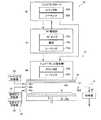
図1Aは、本実施形態のプラズマ生成方法を実施するプラズマ生成装置を含み、薄膜形成方法を実施する薄膜形成装置の構成の一例を示す概略構成図である。
図1Aに示す薄膜形成装置10は、化学気相成長法の一つであるALD(Atomic Layer Deposition)法を用いて薄膜を形成する装置である。本実施形態に用いるALD法は、プラズマを用いて薄膜をより効率よく形成することができるプラズマALD法である。プラズマALD法では、薄膜の主成分を含む原料ガスの原料成分を基板に吸着させた後、この原料成分を、プラズマを用いて活性化した反応ガスの成分(ラジカル分子あるいはラジカル原子)を用いて化学反応をさせることにより、原子層単位で基板に薄膜を形成する処理を、複数回繰り返す。これにより、目的とする薄膜が形成される。
本実施形態のプラズマ生成方法及びプラズマ生成装置は、プラズマALD法及びこの方法を実行する薄膜形成装置に用いられるが、プラズマALD法の他、プラズマを用いたCVD(Chemical Vapor Deposition)法にも適用することができる。また、プラズマ生成方法及びプラズマ生成装置は、薄膜形成の他、ドライエッチング等に用いるプラズマの生成にも適用することができる。FIG. 1A is a schematic configuration diagram illustrating an example of a configuration of a thin film forming apparatus that includes a plasma generating apparatus that performs the plasma generating method of the present embodiment and that performs the thin film forming method.
A thin
The plasma generation method and the plasma generation apparatus of the present embodiment are used for a plasma ALD method and a thin film forming apparatus that executes the method. However, in addition to the plasma ALD method, the plasma generation method and the plasma generation device are also applicable to a CVD (Chemical Vapor Deposition) method using plasma. can do. Further, the plasma generation method and the plasma generation apparatus can be applied to generation of plasma used for dry etching or the like in addition to thin film formation.
(薄膜形成装置)
薄膜形成装置10は、プラズマ生成装置12とガス供給/排気ユニット14を主に有する。プラズマ生成装置12は、プラズマ生成部16と、高周波電源部(RF電源部)18と、インピーダンス整合器20と、レシピコントローラ22と、を含む。ガス供給/排気ユニット14は、原料ガス供給部24と、反応ガス供給部26と、パージガス供給部28と、排気部30と、を含む。(Thin film forming equipment)
The thin
プラズマ生成部16は、減圧容器31と、サセプタ32と、電極34a,34bと、を含む。
減圧容器31は、減圧可能な容器であり、図1Aに示すように、減圧容器31の両側にガス導入口36a,36b,36c及びガス排気口36dを有する。ガス導入口36aは、パージガス供給部28と接続され、窒素ガス等のパージガスを減圧容器31内に導入する。ガス導入口36bは、原料ガス供給部24と接続され、TMA(Trimethylalminium)等の原料ガスを減圧容器31内に導入する。ガス導入口36bは、原料ガス供給部24と接続され、TMAガス等の原料ガスを減圧容器31内に導入する。ガス導入口36cは、反応ガス供給部26と接続され、酸素ガス等の反応ガスを減圧容器31内に導入する。ガス排気口36dは、排気部30と接続され、減圧容器31の空間の圧力を一定に維持するために、原料ガス、反応ガス及びパージガスを排気する。The
The
サセプタ32は、基板Sを載置する載置台として機能し、図1A中の上下方向に移動可能になっている。薄膜の形成時、サセプタ32は最上位置に移動し、薄膜形成前及び後においては、減圧容器31から基板を取り出すために、サセプタ32は下方に下降し、減圧容器31に設けられた図示されないゲートが開いて基板Sを取り出すことができるようになっている。 The susceptor 32 functions as a mounting table on which the substrate S is mounted, and is movable in the vertical direction in FIG. 1A. When the thin film is formed, the
電極34aは、減圧容器31の成膜空間の上部に基板Sに対向するように設けられた金属製板部材であり、RF電源部18からインピーダンス整合器20を介して高周波電力の供給を受ける。電極34bは、サセプタ32の上面に設けられた金属製板部材であり、基板Sを載せるとともに、電極34aと対向するように設けられ、接地されている。電極34aに高周波電力が供給されることにより、減圧容器31内の減圧雰囲気中の反応ガスを用いてプラズマが生成される。すなわち、電極34a,34bは、プラズマを生成する静電容量型プラズマ生成電極である。 The
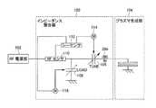
図1Bは、インピーダンス整合器20の一例の回路構成図である。インピーダンス整合器20は、プラズマ生成部16とRF電源部18との間に接続され、プラズマ生成部16に給電する伝送部のインピーダンスが、電力の給電により着火したプラズマの生成期間中のプラズマ生成部16のインピーダンスと整合した状態で電力をプラズマ生成部16に供給する。インピーダンス整合器20は、図1Bに示すように、シーケンサ20aと、カウンタ部20bと、RFセンサ20cと、可変コンデンサ20d,20eと、駆動モータ20f,20gと、インダクタ20hと、を有する。 FIG. 1B is a circuit configuration diagram of an example of the
インピーダンス整合器20は、可変コンデンサ20dがRF電源部18と電極34aとの間で直列に接続され、可変コンデンサ20eは電極34aに対して並列接続された回路構成である。RFセンサ20cによるインピーダンスの不整合の検知結果に応じて、駆動モータ20f,20gが駆動する。これにより、プラズマ生成部16に給電する伝送部のインピーダンスがプラズマの生成期間中のプラズマ生成部16のインピーダンスと整合するように、シーケンサ20aは駆動モータ20f,20gの駆動動を制御する。
具体的には、RF電源部18と電極34aとの間には、RFセンサ20cと、可変コンデンサ20dと、インダクタ20hが、順番に直列接続して設けられている。RFセンサ20cは、RF電源部18が出力する電力、すなわちプラズマ生成部16への入射電力と、プラズマ生成部16によって反射された反射電力との間の比率を計測する。この計測結果に基づいて、インピーダンスの不整合の状態を検知することができる。RFセンサ20cの検知結果は、シーケンサ20aに送られ、インピーダンスの整合(マッチング)のためのシーケンス制御に用いられる。The
Specifically, an
駆動モータ20f,20gは、可変コンデンサ20d,20eのキャパシタンスを調整するためにシーケンサ20aの指示に基づいて駆動する。カウンタ部20bは、RF電源部18の電力が立ち上がって(OFFからONに変化して)行われるインピーダンスマッチングの自動整合の回数(マッチング自動整合回数)を、この電力が立ち下がる時(ONからOFFに変化した時)にカウントする。マッチング自動整合回数が予め設定された規定値以内であるときは、シーケンサ20aはシーケンス制御に従って、インピーダンスマッチングの自動整合(マッチング)の制御を行う。マッチング自動整合回数が予め設定された規定値を超えるときは、シーケンサ20aはインピーダンスマッチングの自動整合の制御を行わない。 The
RF電源部18は、図1Aに示すようにシーケンサ18aと、電源18bと、RFセンサ18cとを含む。図1Bでは、シーケンサ18aと、電源18bと、RFセンサ18cの図示は省略されている。 As shown in FIG. 1A, the RF
RFセンサ18cは、プラズマ生成部16に入射する入射電力およびプラズマ生成部16によって反射された反射電力を測定する。この測定結果に基づいて、RF電源部18は、プラズマの着火の発生を検知することができ、プラズマの着火の有無を知らせるプラズマ着火モニタ信号をレシピコントローラ22に送る。電源18bは、RF電力を例えば2000Wまで供給できるように構成されている。RF電力は、例えば13.5MHzの高周波の電力である。
シーケンサ18aは、RF電力の出力、プラズマの着火の有無の判定、及びプラズマの着火によってRF電源部18の出力する電力を低下させる処理等を行うように制御する。The
The
レシピコントローラ22は、後述する図2(a)〜(e)の処理を制御管理する。レシピコントローラ22は、シーケンサ22aと、カウンタ部22bを含む。レシピコントローラ22は、RF電源部18及びインピーダンス整合器20への指令を行って、RF電源部18及びインピーダンス整合器20の動作を制御するとともに、RF電源部18から送られるプラズマの着火の有無を知らせるプラズマ着火モニタ信号を受け、プラズマの着火を知ることができる。これにより、カウンタ部22bは、未着火回数、未着火サイクル回数をカウントすることができる。さらに、カウンタ部22bは、ALDサイクル回数をカウントする。
シーケンサ22aは、RF電源部18及びインピーダンス整合器20の動作を制御するための各種制御信号を送るとともに、カウンタ部22bによる未着火回数や未着火サイクル回数のカウント結果を得ることで、プラズマを用いた薄膜の形成が有効に行われたか否かの情報を記憶する。上記情報は、必要に応じて図示されないディスプレイに表示されることによりオペレータに通知することができる。The
The
図2(a)〜(e)は、薄膜形成方法における各操作のタイミングの一例を示すタイミングチャートである。
まず、減圧容器31内で、所定の圧力、例えば10〜1000Paの減圧雰囲気で、図2(a)に示すように、原料ガスがガス導入口36bから供給され、原料ガスの成分である薄膜の原料成分が基板Sに原子層の単位で吸着される。その際、一定の減圧雰囲気に維持されるように、ガス排気口36dから原料ガスは同時に排気される。この後、原料ガスの供給は終了する。この後、図2(b)に示すように、パージガスがガス導入口36aから減圧容器31内に供給される。このパージガスの供給により、減圧容器31内に残存する原料ガスがパージガスとともに確実にガス排気口36dから排気される。
この状態で、図2(c)に示すように、反応ガスがガス導入口36cから減圧容器31内に供給される。このとき、ガス排気口36dから常時反応ガスの排気が行われ、減圧容器31内は一定の圧力に維持されている。反応ガスの供給中、図2(d)に示すように、反応ガスの供給から僅かに遅れてRF電源部18は高周波電力を出力し、電極34a,34b間に高周波の電圧が印加される。これにより、電極34a,34bの間の空間で、反応ガスを用いたプラズマが生成される。このプラズマによって反応ガスの一部が電離したイオンから、中性状態であるがラジカル状態の分子(ラジカル分子)または原子(ラジカル原子)となり、このイオン、ラジカル分子またはラジカル原子が基板Sに吸着した薄膜の原料成分と化学反応を起こす。これにより、基板Sに薄膜を原子層の単位で形成される。この後、図2(e)に示すように、減圧容器31内にパージガスがガス導入口36aから供給されて、減圧容器31内に残存する未反応ガスがパージガスとともに、ガス排気口36dから排気される。このような一連の処理を1サイクルとして、プラズマALD法では、数10〜数1000回のサイクルが繰り返されて、目標の厚さの薄膜が形成される。2A to 2E are timing charts showing an example of the timing of each operation in the thin film forming method.
First, as shown in FIG. 2 (a), a source gas is supplied from a
In this state, as shown in FIG. 2C, the reaction gas is supplied into the
図3(a)は、図2(d)における高周波電力の出力をより具体的に示した図である。図3(a)に示すように、高周波電力の出力は、プラズマALD法のプラズマの断続的な生成を実現するために数10〜数1000回断続的に行われる。このとき、1回の高周波電力の出力において、電力の立ち上がり期間の初期段階と、その後の段階では、出力する電力のレベルを異ならせている。具体的には、RF電源部18は、高周波電力の出力を開始する毎に、プラズマ生成部16でプラズマが着火するように、第1の電力をプラズマ生成部16に出力してプラズマ生成部16に給電する。プラズマの着火後、RF電源部18は、プラズマの生成を維持するように、第1の電力より小さい第2の電力を出力してプラズマ生成部16に給電する。上述したように、プラズマALD法では、数10〜数1000回の断続的な給電がプラズマ生成部16に対して行われるが、このうち、少なくとも1回以上の給電において、RF電源部18の伝送部のインピーダンスは、プラズマの生成を維持する期間中のプラズマ生成部16のインピーダンスと整合した状態にある。 FIG. 3A is a diagram more specifically showing the output of the high-frequency power in FIG. As shown in FIG. 3A, the output of the high-frequency power is intermittently performed several tens to several thousand times in order to realize the intermittent generation of plasma by the plasma ALD method. At this time, in one output of the high frequency power, the level of the output power is different between the initial stage of the power rising period and the subsequent stage. Specifically, the RF
図3(a)における1回の高周波電力の出力は例えば0.1秒〜数秒であり、この期間、例えば数MHz〜数10MHzの高周波の電力が連続的に出力する。1回の高周波電力の立ち上がりから例えば最大0.1秒の間、より具体的には例えば20m秒の間、第1の電力W1はRF電源部18から出力され電極34aに給電される。第1の電力W1は、例えば、2000Wである。この後、出力する電力は低下し、RF電源部18は、第2の電力W2を例えば0.6秒間、出力する。第2の電力W2は、例えば、1000Wである。第1の電力W1の出力時間は、減圧容器31内でプラズマが着火したことがRFセンサ18cによって検知され、出力電圧を低下させるまでの時間である。このため、第1の電力W1の出力時間は、第2の電力W2の出力時間よりも短い。なお、プラズマが着火するまでの時間は厳密には一定でないため、第1の電力W1の出力時間は僅かに変化する。しかし、プラズマが着火する場合、電力の供給から一定の時間の範囲内で着火するので、この一定の時間の範囲を定めて上限の時間とする。上述の例では、例えば0.1秒を上限の時間とする。すなわち、RF電源部18から出力する第1の電力W1は、RF電源部18のRFセンサ18cがプラズマを検知するまで継続して行われる。また、RF電源部18から出力する第2の電力W2を長時間維持してプラズマを長時間生成しても、薄膜の形成を促進しないばかりか、プラズマによって薄膜の表面は損傷しやすくなり、薄膜の均一な膜質を維持することは難しくなる。このため、第2の電力W2の出力時間も、原子層単位で化学反応を発生させる時間程度とし、可能な限り短くすることが好ましい。In FIG. 3A, the output of one high frequency power is, for example, 0.1 seconds to several seconds, and during this period, for example, high frequency power of several MHz to several tens of MHz is continuously output. The first power W1 is output from the RF
また、図3(b)は、インピーダンス整合器20が行うインピーダンスの整合(マッチング)を自動的に行うためのマッチング自動整合制御信号のON状態の期間を示す図である。すなわち、プラズマALD法では、給電を周期的に行う一連の処理を行うことにより、プラズマの着火及び生成が周期的に行われる。このとき、プラズマALD法における一連の処理の開始から予め定められた回数の給電の期間内に、プラズマ生成中のプラズマ生成部16のインピーダンスと電力を伝送する伝送部(RF電源部18から電極部34aまでの給電線)のインピーダンス(例えば50Ω)が整合するように、インピーダンス整合器20が調整される。上述したように、1サイクルのALD処理では、第2の電力W2の出力は可能な限り短く行われ、例えば0.6秒である。この間に、インピーダンスの整合(マッチング)を行うことは比較的難しいことから、プラズマALD法における複数のサイクルのALD処理のうち予め定めたサイクル数、例えば図3(b)に示す例では10回のALD処理の期間を、インピーダンスの自動整合を行う期間として定める。インピーダンスの自動整合を行う期間は、例えば、6回、4回等に定めることができる。インピーダンスの自動整合を行う期間に調整されたインピーダンス整合器20の調整した状態、すなわち、可変コンデンサ20d,20eのキャパシタンスは、これ以降のサイクルのALD処理において固定される。FIG. 3B is a diagram illustrating a period of an ON state of the matching automatic matching control signal for automatically performing impedance matching (matching) performed by the
なお、インピーダンスの整合は、プラズマ生成中のプラズマ生成部16のインピーダンスと高周波電力を伝送する伝送部のインピーダンスが整合するように行われるので、プラズマが未着火状態の電力の立ち上がり期間中においてはインピーダンスは整合状態にない。このため、プラズマ生成部16に入射する電力の多くは反射され、プラズマ生成部16に供給される有効な電力は少ない。しかし、上述したように、第2の電力W2より大きな第1の電力W1が供給されるので、プラズマ生成部16に入射する電力の比較的多くが反射されてもプラズマが着火可能な有効な電力がプラズマ生成部16に供給される。一方、伝送部のインピーダンスはプラズマ生成中のプラズマ生成部16のインピーダンスと整合するように調整されているので、プラズマ着火後、第1の電力W1より低い第2の電力W2がプラズマ生成部16に入射しても、プラズマの生成に十分な有効な電力が反射することなくプラズマ生成部16に供給される。以下、この点を詳細に説明する。The impedance matching is performed so that the impedance of the
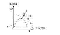
図4は、プラズマ生成部16の各状態に対する、インピーダンス整合器20における可変コンデンサ20f、20gのキャパシタンスの位置をそれぞれ模式的に示す図である。図4では、プラズマ未着火状態、あるいはプラズマ生成状態においてインピーダンスを整合したときの可変コンデンサ20d,20eのキャパシタンスC2,C1の相対値をそれぞれ座標系の横軸及び縦軸に採っている。点Aは、プラズマが生成されていない状態でのプラズマ生成部16の整合点である。点Aは、電極34a,34bの間隔、大きさ、形状等に依存し、供給される電力の大小、減圧雰囲気の圧力、あるいは反応ガスの濃度等に依存せず、減圧容器31内の壁面等の汚れにもほとんど依存しない。点Bは、従来、プラズマ生成部16に設定されるプラズマ着火点である。本来、プラズマの未生成状態におけるインピーダンスの整合は点Aで実現される。点Aは低い電力で効率よくプラズマの着火を行うことができる点であるが、点Bをプラズマ着火点として定めるのは、後述するプラズマ生成状態におけるインピーダンスが整合する点を点Aから点Dに近づけ、駆動モータ20f,20gを用いたインピーダンスの整合を短時間に行うためである。勿論、点Bは、第2の電力W2においてプラズマの着火を可能にする限界線Cより内側に位置する。
一方、点Dは、プラズマが着火してプラズマが生成したときのインピーダンスが整合するプラズマ整合点である。この点Dは、プラズマ生成の条件、例えば、電力の大小、減圧の圧力、反応ガスの分圧、減圧容器31内部の汚れ等によってある範囲内で位置が変動する。いま、点A、点B及び点Dの座標上の経路が直線上に並んでいるとして、キャパシタンスC2,C1の状態変化を表す軸Sを定める。FIG. 4 is a diagram schematically illustrating the positions of the capacitances of the
On the other hand, the point D is a plasma matching point where impedance is matched when the plasma is ignited to generate the plasma. The position of the point D fluctuates within a certain range depending on plasma generation conditions, for example, the magnitude of electric power, the pressure of reduced pressure, the partial pressure of a reactive gas, and the contamination inside the reduced
図5は、点Aから点Bを通り点Dに至る上記軸Sを横軸に、縦軸に電極34a,34b間に印加される電圧をとったときの、電極34a,34b間の印加電圧の変化を示している。
図5中、プラズマの未生成状態における整合点である点AにキャパシタンスC2,C1を定めたときの電極34a,34b間の印加電圧の変化を示す曲線L1,L2を示している。曲線L1は、RF電源部18が第1の電力W1を出力してプラズマ生成部16に給電したときの曲線であり、曲線L2は、RF電源部18が第2の電力W2を出力してプラズマ生成部16に給電したときの曲線である。また、プラズマ生成中の整合点である点Dにインピーダンス整合器20の可変抵抗20f,20gのキャパシタンスC2,C1を固定し、RF電源部18が第2の電力W2を出力してプラズマ生成部16に給電したときの電極34a,34b間の印加電圧の変化を示す曲線L3を示している。FIG. 5 shows the applied voltage between the
In FIG. 5, curves L1 and L2 showing changes in applied voltage between the
RF電源部18が第1の電力W1を出力してプラズマ生成部16に給電したときの曲線L1における電極34a,34b間の印加電圧は、曲線L2の限界線Cにおける電極34a,34b間の印加電圧に比べて高い。このため、点Dの位置にキャパシタンスC2,C1を定めた場合であっても、RF電源部18が第1の電力W1を出力してプラズマ生成部16に給電することにより、プラズマの未生成時インピーダンスが不整合の状態であっても、プラズマを着火することができる。また、キャパシタンスC2,C1を点Dの位置に定めているので、プラズマ着火後は、RF電源部18が第1の電力W1より低い第2の電力W2を出力してプラズマ生成部16に給電しても、プラズマの生成を維持することができる。
しかも、一旦、プラズマ整合点である点Dが見出されると、キャパシタンスC2,C1を点Dの位置に固定するので、駆動モータ20f,20gによる調整時間が全くなくなる。このため、第2の電力W2を用いて効率的にプラズマの生成を行うことができる。
Moreover, once the point D, which is a plasma matching point, is found, the capacitances C2 and C1 are fixed at the position of the point D, so that the adjustment time by the
図6(a)は、レシピコントローラ22において設定されている第1の電力W1の出力であり、プラズマ生成部16への入射電力の一例を示している。この例は、第1の電力W1のレベルが最大であり、出力時間が最長である例を示している。すなわち、図6(a)は、レシピコントローラ22が予め設定した第1の電力W1の最大レベル、及び最長出力時間を示している。第2の電力W2の出力継続時間はT2である。
本実施形態では、この最大レベル及び最長出力時間を第1の電力W1の出力レベル及び出力時間の上限とする。
図6(b)は、実際に行われる第1の電力W1の出力の一例を示している。図6(b)に示す例では、RF電源部18のRFセンサ18cが上述したようにプラズマ着火を検知することにより、第1の電力W1の出力を停止し、第2の電力W2の出力に切り替わる。したがって、プラズマは、電力の立ち上がり途中で第1の電力W1の前に着火する。
すなわち、第1の電力W1の出力時間はレシピコントローラ22において設定されている上記最長出力時間より短い。このようにRFセンサ18cがプラズマ着火を検知すると、第1の電力W1の出力を停止し、第2の電力W2の出力を開始するのは、プラズマが着火すると、第2の電力W2より大きな第1の電力W1をRF電源部18が出力する必要はなく、第2の電力W2を用いてプラズマを継続して生成すればよいからである。このように、第1の電力W1の出力時間は、電力の立ち上がり期間中に発生するプラズマの着火の時点に依存するとともに、第1の電力W1のレベルも変動する。しかし、プラズマ未生成の状態では、伝送部のインピーダンスがプラズマ生成部16と整合していないので、電力の立ち上がり期間中にプラズマが着火する時の電力は、第2の電力W2より高い。つまり、図6(b)に示す第1の電力W1は、レシピコントローラ22が予め設定した電力ではなく、電力の立ち上がり期間中にプラズマが着火することで、第2の電力W2に切り替える時の電力である。本実施形態における第1の電力W1は、このようにプラズマの生成を維持するために用いる予め定めた第2の電力W2より大きく、プラズマの着火のために用いる電力である。なお、第2の電力W2を第1の電力W1より小さくすることで、電力の大きな第1の電力W1によって生成されるプラズマにより、形成された薄膜の表面が損傷することを防止することができる。なお、第2の電力W2の出力継続時間は、図6(a)に示す継続時間と同じであり、T2である。FIG. 6A is an output of the first power W1 set in the
In the present embodiment, the maximum level and the longest output time are used as the upper limit of the output level and output time of the first power W1 .
FIG. 6B shows an example of the output of the first power W1 that is actually performed. In the example shown in FIG. 6B, when the
That is, the output time of the first power W1 is shorter than the longest output time set in the
(プラズマ生成フロー)
図7A〜7Bは、プラズマ生成方法のフローの一部を詳細に説明するフローチャートである。
図7Aはレシピコントローラ22のフローを示し、図7BはRF電源部18のフローを示し、図7Cはインピーダンス整合器20のフローを示す。(Plasma generation flow)
7A to 7B are flowcharts illustrating in detail a part of the flow of the plasma generation method.
7A shows the flow of the
まず、ALD法による薄膜の形成のためのバッチ処理を開始する。バッチ処理は、図2(a)〜(e)に示す処理を1サイクルのALDサイクルとして複数回のALDサイクルを含む。バッチ処理を開始すると、図7Aに示すように、レシピコントローラ22は、パラメータであるALDサイクル回数N1、マッチング自動整合回数N2、未着火回数M1、未着火サイクル回数M2、プラズマ着火時間T1、プラズマ放電時間T2、第1の電力W1の出力時間T3を0にリセットする。First, batch processing for forming a thin film by the ALD method is started. The batch process includes a plurality of ALD cycles with the process shown in FIGS. 2A to 2E as one ALD cycle. When the batch processing is started, as shown in FIG. 7A, the
まず、レシピコントローラ22のシーケンサ22aは、高周波電力を出力するためのRFスタンバイ信号をONにする(ステップS10)。ONになったRFスタンバイ信号は、RF電源部18aのシーケンサ18a及びインピーダンス整合器20のシーケンサ20aに送られる。これにより、シーケンサ18aは、RF電源の出力開始の待機状態になる(ステップS300)。シーケンサ20aは、後述するステップS400、S420に進み、ステップS420で、RF出力(高周波電力の供給)が立ち上がるまで、待機状態になる。 First, the
次に、シーケンサ22aは、ALD法によるサイクル処理を開始する(ステップS20)。まず、図2(a)〜(c)に示す処理が行われ、この後、シーケンサ22aは、パルスON・OFF信号をONにする(ステップS30)。このパルスON・OFF信号は、RF電源部18に送られ、シーケンサ18aはRF出力をONにする(ステップS310)。すなわち、RF電源部18は、高周波電力の供給を開始する。 Next, the
次に、レシピコントローラ22は、プラズマ着火時間T1の計測を開始する(ステップS40)。すなわち、レシピコントローラ22内に設けられたタイマがプラズマ着火時間T1の起動を開始する。シーケンサ22aは、プラズマ着火時間T1が規定時間である0.2秒を経過したか否かを判定する(ステップS50)。この判定の結果が否定である場合(NOの場合)、シーケンサ22aは、RF電源部18からONのプラズマ着火モニタ信号が送られたか否かを判定する(ステップS60)。この判定の結果が否定である場合(NOの場合)、ステップS50に戻る。こうして、RF電源部18からONのプラズマ着火モニタ信号が送られまで、さらに、プラズマ着火時間T1が規定時間を越えるまで、待機する。一方、ステップS50において、プラズマが着火せず、プラズマ着火時間T1が規定時間を経過した場合(YESの場合)、カウンタ部22bは、未着火回数M1を1つ繰り上げて未着火回数M1をカウントし(ステップS70)、シーケンサ22aは、パルスON・OFF信号をOFFにする(ステップS80)。OFFとなったパルスON・OFF信号は、RF電源部18に送られ、RF電源部18では、RF出力(高周波電力の出力)がOFFとなる(ステップS380)。 Next, the
さらに、シーケンサ22aは、未着火回数M1が予め設定された回数である3回を越えたか否かを判定する(ステップS90)。判定の結果が否定である場合(NOの場合)、すなわち、プラズマ未着火回数M1が予め設定された回数以内の場合、ステップS30に戻り、再度、プラズマの着火のための処理を繰り返す。ステップS90の判定において、プラズマ未着火回数M1が予め設定された回数を超えた場合(YESの場合)、カウンタ部22bは、未着火サイクル回数M2を1つ繰り上げて未着火サイクル回数M2をカウントする(ステップS100)。この場合、シーケンサ22aは、プラズマが着火しないので、1つのALDサイクル処理を終了(ステップS110)する。さらに、シーケンサ22aは、未着火サイクル回数M2が予め定められた規定値である3回を越えたか否かを判定する(ステップS120)。この判定の結果が否定である場合(NOの場合)、プラズマの着火及び生成が、今回のALDサイクルでは行われなかったとし、次のALDサイクルに進む。一方、ステップS120の判定の結果が肯定である場合(YESの場合)、すなわち、未着火サイクル回数M2が3回を越えた場合、ALD処理は正常に行われなかったと判断して、シーケンサ22aは、RFスタンバイ信号をOFFにする(ステップS130)。OFFになったRFスタンバイ信号は、RF電源部18に送られ、RF電源部18は、待機状態になる(ステップS390)。こうして、バッチ処理は、プラズマが着火しないので異常終了する。 Further, the
一方、ステップS60の判定により、シーケンサ22aがONのプラズマの着火モニタ信号を得た場合、シーケンサ22aは、未着火回数M1を0にセットし(ステップS140)、さらに、未着火サイクル回数M2を0にセットする(ステップS150)。この後、プラズマは着火したので、シーケンサ22aは、プラズマの放電時間T2の計測を開始する(ステップS160)。シーケンサ22aは、プラズマの放電時間T2が予め規定した時間である0.6秒を経過したか否かを判定する(ステップS170)。こうして、プラズマの放電時間T2が予め規定した時間を経過するまで、シーケンサ22aは、プラズマの生成を継続させる。プラズマの放電時間T2が予め規定した時間を経過した場合(ステップS170においてYESの場合)、シーケンサ22aは、パルスON・OFF信号をOFFにし、ALDサイクル処理を終了する(ステップS180,ステップS190)。OFFになったパルスON・OFF信号は、RF電源部18に送られ、RF電源部18は、RF出力(高周波電力の出力)をOFFにする(ステップS380)。 On the other hand, when the
さらに、カウンタ部22bは、ALDサイクル回数N1を1つ繰り上げてALDサイクル数N1をカウントする(ステップS200)。
この後、シーケンサ22aは、ALDサイクル回数N1が予め定められた規定値に達したか否かを判定する(ステップS210)。この判定の結果が否定の場合(NOの場合)、ステップ20に戻り、次のALDサイクル処理を開始する。一方、ステップS210の判定の結果が肯定である場合(YESの場合)、シーケンサ22aは、RFスタンバイ信号をOFFとする(ステップS220)。OFFとなったRFスタンバイ信号は、RF電源部18に送られ、RF電源部18を高周波電力の出力開始の待機状態にし(ステップS390)、インピーダンス整合器20のカウンタ部20bは、マッチング自動整合回数(パルス数)N2を0にリセットする(ステップS420)。以上で、バッチ処理は正常な状態で終了する。Further, the
Thereafter, the
一方、RF電源部18は、図7Bに示すようなフローの処理を行う。
まず、レシピコントローラ22から送られるONのRFスタンバイ信号により、RF電源は待機状態になる(ステップS300)。この後、レシピコントローラ22から送られるONのパルスON・OFF信号により電源18bは第1の電力W1を出力する(ステップS310)。On the other hand, the RF
First, the RF power supply enters a standby state by an ON RF standby signal sent from the recipe controller 22 (step S300). Thereafter, the
次に、RF電源部18のシーケンサ18aは、図示されないタイマを用いて第1の電力W1の出力時間T3の計測を開始する(ステップS320)。シーケンサ18aは、プラズマが着火したか否かのモニタリングを開始する(ステップS330)。シーケンサ18aは、出力時間T3が予め定めた規定時間である0.1秒を超えたか否かを判定する(ステップS340)。この判定の結果が否定である場合(NOの場合)、さらに、シーケンサ18aは、RF電力(高周波電力)の出力がONの状態か否かを判定する(ステップS350)。この判定の結果が否定の場合(NOの場合)、シーケンサ18aは、プラズマ着火モニタリングを停止する(ステップS360)。一方、ステップS350の判定の結果が肯定の場合(YESの場合)、シーケンサ18aは、プラズマ着火の有無を確認する(ステップS360)。この確認で、プラズマの着火が確認されない場合(ステップS360においてNOの場合)、ステップS340に戻るとともに、シーケンサ18aは、プラズマ着火モニタ信号をOFFにする(ステップS370)。このOFFのプラズマ着火モニタ信号はシーケンサ22aに継続して送られ、ステップS60の判定に用いられる。一方、ステップS360の確認においてプラズマの着火が確認された場合(YESの場合)、シーケンサ18aは、プラズマ着火モニタ信号をONにし(ステップS380)、ONのプラズマ着火モニタ信号はシーケンサ22aに継続して送られ、ステップS60の判定に用いられる。さらに、プラズマ着火モニタ信号をONにした後、シーケンサ18aは、第2の電力W2の出力を開始する(ステップS370)。こうして、プラズマの着火が確認されると即座に、電源18bは、第2の電力W2の出力を開始する。このため、電源18bは、図6(b)に示すように、高周波電力の立ち上がり期間中に大きな第1の電力W1を瞬間的に出力するとともに、プラズマの着火後、第2の電力W2の出力を一定時間維持する。この後、電源18bは、レシピコントローラ22から送られるOFFのパルスON・OFF信号を受けてRF出力(高周波電力の出力)をOFFにする(ステップS380)。また、シーケンサ18aは、レシピコントローラ22から送られるOFFのRFスタンバイ信号を受けてRF電源部18を待機状態にする(ステップS390)。Next, the
一方、インピーダンス整合器20は、図7Cに示すようなフローの処理を行う。まず、シーケンサ20aは、マッチング自動整合回数N2が予め設定された規定値である10回に達したか否かを判定する(ステップS400)。この判定の結果が肯定である場合(YESの場合)、マッチング自動整合は、図3(b)に示すように、以降のRF電力ONのときにおいても行われない。これにより、プラズマ生成時のインピーダンス整合状態に、可変コンデンサ20d,20eは固定される(ステップS410)。 On the other hand, the
一方、ステップS400における判定の結果が否定の場合(NOの場合)、シーケンサ20aは、RF電力の出力がONであって、RF電力(高周波電力)が立ち上がる状態か否かを判定する(ステップS420)。判定の結果が否定である場合、RF電力の出力がONであって、RF電力(高周波電力)が立ち上がる状態になるまで待機する。ステップS420における判定の結果が肯定である場合、シーケンサ20aは、マッチング自動整合の制御を開始する(ステップS430)。インピーダンスの不整合状態は、減圧容器31の内部の汚れ、減圧容器31の圧力、反応ガスの分圧等によって変化する。しかし、バッチ処理の途中で整合状態が変化することは殆ど起こらない。したがって、1回のバッチ処理では、バッチ処理を開始した直後の複数回のALDサイクル、例えば、4回のALDサイクルの期間だけ、マッチング自動整合の制御を行えばよい。マッチング自動整合を、複数回のALDサイクルの期間行うのは、1回のALDサイクルの期間では駆動モータ20f,20gを用いて十分な制御が行えない場合があるからである。上記ALDサイクルのサイクル数は、多くとも10回とすることができる。 On the other hand, when the result of the determination in step S400 is negative (in the case of NO), the
シーケンサ20aは、次に、RF電力の出力がONからOFFに変更されたか否かを判定する(ステップS440)。判定の結果が否定の場合(NOの場合)、シーケンサ20aは、RF電力の出力がONからOFFに変更するまで待機する。一方、ステップS440の判定の結果が肯定の場合(YESの場合)、カウンタ部20bは、マッチング自動整合回数N2を1つ繰り上げてマッチング自動整合回数N2をカウントする(ステップS450)。この後、シーケンサ20aは、マッチング自動整合の制御を停止する(ステップS460)。こうして、シーケンサ20aは、ステップS400に戻る。以上のようにして、インピーダンス整合回路20は、図3(b)に示すような自動整合制御を行う。また、シーケンサ20aは、レシピコントローラ22のシーケンサ22aから送られるOFFのRFスタンバイ信号に応じて、マッチング自動整合回数N2を0にセットする(ステップS470)。 Next, the
以上のように、本実施形態では、プラズマ未生成状態のプラズマ生成部16のインピーダンスに伝送部のインピーダンスが整合した時に必要な着火電力よりも高い第1の電力W1を用いてプラズマを着火させた後、RF電源部18は、プラズマの生成期間中のプラズマ生成部16のインピーダンスとインピーダンスが整合した状態を維持して、第1の電力W1より小さい第2の電力W2に第1の電力W1を切り替えるので、インピーダンスが不整合の状態でもプラズマを着火することができるとともに、プラズマの着火の前後でインピーダンスを整合する必要がない。このため、プラズマの生成のための電力を有効に用いてプラズマを生成することができる。As described above, in the present embodiment, the plasma is ignited using the first power W1 higher than the ignition power required when the impedance of the transmission unit matches the impedance of the
プラズマの着火は、入射電力と反射電力を測定することにより検知され、この検知結果に応じて第1の電力は第2の電力に切り替えられるので、RF電源部18は、不必要に第1の電力の出力を維持する必要はなくなり、より有効に電力を用いてプラズマを生成することができる。 The ignition of the plasma is detected by measuring the incident power and the reflected power, and the first power is switched to the second power according to the detection result. There is no need to maintain the power output, and plasma can be generated more effectively using the power.
複数のALDサイクルを含んだ一連の処理を行うために、RF電源部18が電力を周期的に出力することにより、プラズマの着火及び生成の維持が周期的に行われる場合、一連の処理の開始から予め定められた回数の電力の出力の期間内に、プラズマ生成中のプラズマ生成部16のインピーダンスと整合するように、プラズマ生成部16に接続されたインピーダンス整合器20のインピーダンスは調整されるので、それ以降のプラズマの着火及び生成の維持の処理を安定して行うことができる。 In order to perform a series of processes including a plurality of ALD cycles, when the RF
インピーダンス整合器20の調整が終了した後は、インピーダンス整合器20の調整した状態が固定される場合であってもだ、すなわち可変コンデンサ20d,20eの調整後のキャパシタンスが固定される場合であっても、プラズマ生成後は、電力を供給する伝送部のインピーダンスとプラズマの生成中のプラズマ生成部16のインピーダンスとが整合する状態で第2の電力W2がRF電源部18から出力される。このため、インピーダンスの自動整合が終了すると、プラズマ生成後のインピーダンスの調整を不要とする。したがって、より有効に電力を用いてプラズマを生成し維持することができる。
このようなプラズマの生成は、短時間の間にプラズマの生成及び停止を行う処理を断続的に繰り返すプラズマALD法において特に有効に用いることができる。After the adjustment of the
Such plasma generation can be used particularly effectively in a plasma ALD method in which a process of generating and stopping plasma is repeated intermittently in a short time.
以上、本発明のプラズマ生成方法、この方法を用いた薄膜形成方法及びプラズマ生成装置について詳細に説明したが、本発明は上記実施形態および変形例に限定されず、本発明の主旨を逸脱しない範囲において、種々の改良や変更をしてもよいのはもちろんである。 As described above, the plasma generation method, the thin film formation method using the method, and the plasma generation apparatus according to the present invention have been described in detail. Of course, various improvements and changes may be made.
10 薄膜形成生成装置
12 プラズマ生成装置
14 ガス供給/排気ユニット
16,104 プラズマ生成部
18,102 高周波電源部(RF電源部)
20,100 インピーダンス整合器
20a,112 シーケンサ
20b カウンタ部
20c,110 RFセンサ
20d,20e,106,108 可変コンデンサ
20f,20g,114,116 駆動モータ
20h インダクタ
22 レシピコントローラ
24 原料ガス供給部
26 反応ガス供給部
28 パージガス供給部
30 排気部
31 減圧容器
32 サセプタ
34a,34b 電極
DESCRIPTION OF
20, 100
Claims (9)
Translated fromJapaneseプラズマを着火するために、高周波電源部が第1の電力を出力してプラズマ生成部に給電するステップと、
前記プラズマの着火後、前記プラズマの生成を維持するために、前記高周波電源部が前記第1の電力より小さい第2の電力を出力して前記プラズマ生成部に給電するステップと、を有し、
前記プラズマを着火するとき、及び前記プラズマの生成を維持するとき、前記プラズマ生成部に電力を伝送する伝送部のインピーダンスが、前記プラズマの生成を維持する期間中の前記プラズマ生成部のインピーダンスと整合した状態で、前記高周波電源部は、前記第1の電力あるいは前記第2の電力を出力し、
前記高周波電源部が電力を前記プラズマ生成部に供給するとき、前記プラズマの着火の開始を検出するために前記プラズマ生成部で反射した反射電力を測定し、予め定めた時間内において、前記プラズマの着火の開始を検出したとき、前記予め定めた時間内に前記第1の電力を前記第2の電力に切り替え、
前記予め定めた時間内において、前記プラズマの着火の開始を検出しないとき、前記第1の電力の出力を中止した後、再度、前記プラズマを着火するために、前記高周波電源部が前記第1の電力を出力してプラズマ生成部に給電するステップを行う、ことを特徴とするプラズマ生成方法。A plasma generation method for generating plasma,
In order to ignite the plasma, the high-frequency power supply unit outputs a first power to supply power to the plasma generation unit;
After the ignition of the plasma, in order to maintain the generation of the plasma, the high-frequency power supply unit outputs a second power smaller than the first power to feed the plasma generation unit,
When the plasma is ignited and when the generation of the plasma is maintained, the impedance of the transmission unit that transmits power to the plasma generation unit matches the impedance of the plasma generation unit during the period for maintaining the generation of the plasma In this state, the high frequency power supply unit outputs the first power or the second power,
When the high-frequency power supply supplies power to the plasma generator, the reflected power reflected by the plasma generator is measured to detect the start of ignition of the plasma, and the plasma power is measured within a predetermined time. When the start of ignition is detected, the first power is switched to the second power within the predetermined time,
When the start of the ignition of the plasma is not detected within the predetermined time, the high frequency power supply unit is configured to ignite the plasma again after stopping the output of the first power. A plasma generation method characterizedby performing a step of outputting electric power and supplying power to the plasma generation unit .
前記一連の処理の開始から予め定められた回数の給電の期間内に、前記伝送部のインピーダンスと前記プラズマ生成中の前記プラズマ生成部のインピーダンスが整合するように、前記プラズマ生成部に接続されたインピーダンス整合器が調整される、請求項1に記載のプラズマ生成方法。Ignition of the plasma and maintenance of generation are periodically performed by performing a series of processes of periodically feeding the first power and the second power as a set,
Connected to the plasma generation unit so that the impedance of the transmission unit and the impedance of the plasma generation unit during plasma generation match within a predetermined number of power supply periods from the start of the series of processes. The plasma generation method according to claim 1, wherein the impedance matching unit is adjusted.
基板に形成しようとする原料ガスの薄膜成分を減圧容器内で吸着させる第1ステップと、
前記原料ガスの薄膜成分を前記基板に吸着させた後、前記減圧容器内から前記原料ガスを排気する第2ステップと、
前記減圧容器内に反応ガスを導入し、前記反応ガスを用いて前記プラズマの着火及び前記プラズマの生成維持を、前記第1の電力及び前記第2の電力を用いて行うことにより、前記プラズマで活性化した前記反応ガスの成分を用いて、前記基板に吸着した前記原料ガスの薄膜成分と反応させて薄膜を形成する第3ステップと、
前記反応ガスを前記減圧容器内から排気する第4ステップと、を有し、
前記第1ステップ〜前記第4ステップを繰り返し行うことにより、前記形成される薄膜を厚くする、薄膜形成方法。A thin film forming method using the plasma generation method according to any one of claims 1 to 4,
A first step of adsorbing a thin film component of a source gas to be formed on a substrate in a decompression vessel;
A second step of exhausting the source gas from the reduced pressure vessel after adsorbing the thin film component of the source gas on the substrate;
A reaction gas is introduced into the decompression vessel, and the plasma is ignited using the reaction gas and the generation and maintenance of the plasma are performed using the first power and the second power. A third step of reacting with the thin film component of the source gas adsorbed on the substrate using the activated component of the reactive gas to form a thin film;
A fourth step of exhausting the reaction gas from the decompression vessel,
A thin film forming method for thickening the thin film to be formed by repeatedly performing the first step to the fourth step.
高周波電源部と、
前記高周波電源部からの電力の供給によりプラズマを生成するプラズマ生成部と、
前記プラズマ生成部と前記高周波電源部との間に接続されるインピーダンス整合器と、
前記高周波電源部が電力を前記プラズマ生成部に供給するとき、予め定めた時間内において、前記プラズマ生成部で反射した反射電力を測定することにより前記プラズマの着火の開始を検出するセンサと、
前記電力の出力開始時に、前記プラズマ生成部によって前記プラズマが着火するために第1の電力を出力し、前記プラズマの着火後、前記プラズマの生成を維持するために前記第1の電力より小さい第2の電力を出力するように前記高周波電源部を制御し、さらに、前記プラズマを着火するとき、及び前記プラズマの生成を維持するとき、前記プラズマ生成部に電力を伝送する伝送部のインピーダンスが、前記プラズマの生成を維持する期間中の前記プラズマ生成部のインピーダンスと整合した状態になるように前記伝送部のインピーダンスを制御する制御部と、を有し、
前記制御部は、さらに、前記高周波電源部が電力を前記プラズマ生成部に供給するとき、予め定めた時間内において、前記センサが前記プラズマの着火の開始を検出したとき、前記予め定めた時間内に前記第1の電力を前記第2の電力に切り替えさせ、前記予め定めた時間内において、前記センサが前記プラズマの着火の開始を検出しないとき、前記第1の電力の出力を中止させた後、再度、前記プラズマを着火するために、前記高周波電源部に前記第1の電力を出力させて前記プラズマ生成部に給電させる、ことを特徴とするプラズマ生成装置。A plasma generation device for generating plasma,
A high frequency power supply,
A plasma generator that generates plasma bysupplying power from the high-frequency powersupply ; and
An impedance matching unit connected between the plasma generation unit and the high-frequency power supplyunit ;
When the high frequency power supply unit supplies power to the plasma generation unit, a sensor that detects the start of ignition of the plasma by measuring the reflected power reflected by the plasma generation unit within a predetermined time;
At the start of the output of the power, the plasma generation unit outputs a first power to ignite the plasma, and after the plasma is ignited, a first power smaller than the first power is maintained to maintain the generation of the plasma. Thehigh frequency power supply unit is controlled to output power of 2, and when the plasma is ignited and when the generation of the plasma is maintained, the impedance of the transmission unit that transmits power to the plasma generation unit is:A control unit that controls the impedance of the transmission unit so as to be matched with the impedance of the plasma generation unit during a period of maintaining the generation of the plasma,
The control unit further includes, within a predetermined time when the sensor detects the start of ignition of the plasma within a predetermined time when the high frequency power supply unit supplies power to the plasma generation unit. The first power is switched to the second power, and the output of the first power is stopped when the sensor does not detect the start of ignition of the plasma within the predetermined time. In order to ignite the plasma again, the high-frequency power supply unit outputs the first power and feeds the plasma generation unit.
前記インピーダンス整合器は、前記一連の処理を行うとき、前記一連の処理の開始から予め定められた回数の給電の期間内に、前記伝送部のインピーダンスと、前記プラズマ生成中の前記プラズマ生成部のインピーダンスとが整合するように調整される、請求項6に記載のプラズマ生成装置。Ignition of the plasma and maintenance of generation are periodically performed by performing a series of processes of periodically feeding the first power and the second power as a set,
When performing the series of processes, the impedance matching unit includes the impedance of the transmission unit and the plasma generation unit during plasma generation within a predetermined number of power supply periods from the start of the series of processes. The plasma generation apparatus according to claim 6, wherein the plasma generation apparatus is adjusted so as to match impedance.
9. The plasma generating apparatus according to claim 6, wherein an output time of the first power is shorter than an output time of the second power.
Priority Applications (1)
| Application Number | Priority Date | Filing Date | Title |
|---|---|---|---|
| JP2012060164AJP5547763B2 (en) | 2012-03-16 | 2012-03-16 | Plasma generating method, thin film forming method using the method, and plasma generating apparatus |
Applications Claiming Priority (1)
| Application Number | Priority Date | Filing Date | Title |
|---|---|---|---|
| JP2012060164AJP5547763B2 (en) | 2012-03-16 | 2012-03-16 | Plasma generating method, thin film forming method using the method, and plasma generating apparatus |
Publications (2)
| Publication Number | Publication Date |
|---|---|
| JP2013196822A JP2013196822A (en) | 2013-09-30 |
| JP5547763B2true JP5547763B2 (en) | 2014-07-16 |
Family
ID=49395544
Family Applications (1)
| Application Number | Title | Priority Date | Filing Date |
|---|---|---|---|
| JP2012060164AActiveJP5547763B2 (en) | 2012-03-16 | 2012-03-16 | Plasma generating method, thin film forming method using the method, and plasma generating apparatus |
Country Status (1)
| Country | Link |
|---|---|
| JP (1) | JP5547763B2 (en) |
Families Citing this family (268)
| Publication number | Priority date | Publication date | Assignee | Title |
|---|---|---|---|---|
| US9997357B2 (en) | 2010-04-15 | 2018-06-12 | Lam Research Corporation | Capped ALD films for doping fin-shaped channel regions of 3-D IC transistors |
| US9257274B2 (en) | 2010-04-15 | 2016-02-09 | Lam Research Corporation | Gapfill of variable aspect ratio features with a composite PEALD and PECVD method |
| US20130023129A1 (en) | 2011-07-20 | 2013-01-24 | Asm America, Inc. | Pressure transmitter for a semiconductor processing environment |
| US10714315B2 (en) | 2012-10-12 | 2020-07-14 | Asm Ip Holdings B.V. | Semiconductor reaction chamber showerhead |
| JP6538300B2 (en) | 2012-11-08 | 2019-07-03 | ノベラス・システムズ・インコーポレーテッドNovellus Systems Incorporated | Method for depositing a film on a sensitive substrate |
| US20160376700A1 (en) | 2013-02-01 | 2016-12-29 | Asm Ip Holding B.V. | System for treatment of deposition reactor |
| TWI654336B (en)* | 2013-12-30 | 2019-03-21 | 美商蘭姆研究公司 | Plasma enhanced atomic layer deposition with pulsed plasma exposure |
| JP6415215B2 (en)* | 2014-09-26 | 2018-10-31 | 株式会社Kokusai Electric | Substrate processing apparatus, semiconductor device manufacturing method, and program |
| US10941490B2 (en) | 2014-10-07 | 2021-03-09 | Asm Ip Holding B.V. | Multiple temperature range susceptor, assembly, reactor and system including the susceptor, and methods of using the same |
| US9564312B2 (en) | 2014-11-24 | 2017-02-07 | Lam Research Corporation | Selective inhibition in atomic layer deposition of silicon-containing films |
| CN105826154B (en) | 2015-01-06 | 2017-12-19 | 北京北方华创微电子装备有限公司 | For the impedance matching methods and device of pulse radiation frequency power supply |
| US10276355B2 (en) | 2015-03-12 | 2019-04-30 | Asm Ip Holding B.V. | Multi-zone reactor, system including the reactor, and method of using the same |
| US10566187B2 (en) | 2015-03-20 | 2020-02-18 | Lam Research Corporation | Ultrathin atomic layer deposition film accuracy thickness control |
| US10211308B2 (en) | 2015-10-21 | 2019-02-19 | Asm Ip Holding B.V. | NbMC layers |
| US11139308B2 (en) | 2015-12-29 | 2021-10-05 | Asm Ip Holding B.V. | Atomic layer deposition of III-V compounds to form V-NAND devices |
| US10529554B2 (en) | 2016-02-19 | 2020-01-07 | Asm Ip Holding B.V. | Method for forming silicon nitride film selectively on sidewalls or flat surfaces of trenches |
| US10343920B2 (en) | 2016-03-18 | 2019-07-09 | Asm Ip Holding B.V. | Aligned carbon nanotubes |
| JP6695190B2 (en) | 2016-03-29 | 2020-05-20 | 東京エレクトロン株式会社 | Anomaly detection system and control board |
| US10367080B2 (en) | 2016-05-02 | 2019-07-30 | Asm Ip Holding B.V. | Method of forming a germanium oxynitride film |
| US9773643B1 (en) | 2016-06-30 | 2017-09-26 | Lam Research Corporation | Apparatus and method for deposition and etch in gap fill |
| US10062563B2 (en) | 2016-07-01 | 2018-08-28 | Lam Research Corporation | Selective atomic layer deposition with post-dose treatment |
| US9859151B1 (en) | 2016-07-08 | 2018-01-02 | Asm Ip Holding B.V. | Selective film deposition method to form air gaps |
| US10612137B2 (en) | 2016-07-08 | 2020-04-07 | Asm Ip Holdings B.V. | Organic reactants for atomic layer deposition |
| US9812320B1 (en) | 2016-07-28 | 2017-11-07 | Asm Ip Holding B.V. | Method and apparatus for filling a gap |
| US9887082B1 (en) | 2016-07-28 | 2018-02-06 | Asm Ip Holding B.V. | Method and apparatus for filling a gap |
| KR102532607B1 (en) | 2016-07-28 | 2023-05-15 | 에이에스엠 아이피 홀딩 비.브이. | Substrate processing apparatus and method of operating the same |
| US11532757B2 (en) | 2016-10-27 | 2022-12-20 | Asm Ip Holding B.V. | Deposition of charge trapping layers |
| US10714350B2 (en) | 2016-11-01 | 2020-07-14 | ASM IP Holdings, B.V. | Methods for forming a transition metal niobium nitride film on a substrate by atomic layer deposition and related semiconductor device structures |
| KR102546317B1 (en) | 2016-11-15 | 2023-06-21 | 에이에스엠 아이피 홀딩 비.브이. | Gas supply unit and substrate processing apparatus including the same |
| KR102762543B1 (en) | 2016-12-14 | 2025-02-05 | 에이에스엠 아이피 홀딩 비.브이. | Substrate processing apparatus |
| US11447861B2 (en) | 2016-12-15 | 2022-09-20 | Asm Ip Holding B.V. | Sequential infiltration synthesis apparatus and a method of forming a patterned structure |
| US11581186B2 (en) | 2016-12-15 | 2023-02-14 | Asm Ip Holding B.V. | Sequential infiltration synthesis apparatus |
| US10269558B2 (en) | 2016-12-22 | 2019-04-23 | Asm Ip Holding B.V. | Method of forming a structure on a substrate |
| US11390950B2 (en) | 2017-01-10 | 2022-07-19 | Asm Ip Holding B.V. | Reactor system and method to reduce residue buildup during a film deposition process |
| US10468261B2 (en) | 2017-02-15 | 2019-11-05 | Asm Ip Holding B.V. | Methods for forming a metallic film on a substrate by cyclical deposition and related semiconductor device structures |
| US10410836B2 (en)* | 2017-02-22 | 2019-09-10 | Lam Research Corporation | Systems and methods for tuning to reduce reflected power in multiple states |
| US10770286B2 (en) | 2017-05-08 | 2020-09-08 | Asm Ip Holdings B.V. | Methods for selectively forming a silicon nitride film on a substrate and related semiconductor device structures |
| US12040200B2 (en) | 2017-06-20 | 2024-07-16 | Asm Ip Holding B.V. | Semiconductor processing apparatus and methods for calibrating a semiconductor processing apparatus |
| US11306395B2 (en) | 2017-06-28 | 2022-04-19 | Asm Ip Holding B.V. | Methods for depositing a transition metal nitride film on a substrate by atomic layer deposition and related deposition apparatus |
| KR20190009245A (en) | 2017-07-18 | 2019-01-28 | 에이에스엠 아이피 홀딩 비.브이. | Methods for forming a semiconductor device structure and related semiconductor device structures |
| US11374112B2 (en) | 2017-07-19 | 2022-06-28 | Asm Ip Holding B.V. | Method for depositing a group IV semiconductor and related semiconductor device structures |
| US10590535B2 (en) | 2017-07-26 | 2020-03-17 | Asm Ip Holdings B.V. | Chemical treatment, deposition and/or infiltration apparatus and method for using the same |
| US10692741B2 (en) | 2017-08-08 | 2020-06-23 | Asm Ip Holdings B.V. | Radiation shield |
| US10770336B2 (en) | 2017-08-08 | 2020-09-08 | Asm Ip Holding B.V. | Substrate lift mechanism and reactor including same |
| US11769682B2 (en) | 2017-08-09 | 2023-09-26 | Asm Ip Holding B.V. | Storage apparatus for storing cassettes for substrates and processing apparatus equipped therewith |
| US11830730B2 (en) | 2017-08-29 | 2023-11-28 | Asm Ip Holding B.V. | Layer forming method and apparatus |
| US11056344B2 (en) | 2017-08-30 | 2021-07-06 | Asm Ip Holding B.V. | Layer forming method |
| US11295980B2 (en) | 2017-08-30 | 2022-04-05 | Asm Ip Holding B.V. | Methods for depositing a molybdenum metal film over a dielectric surface of a substrate by a cyclical deposition process and related semiconductor device structures |
| KR102491945B1 (en) | 2017-08-30 | 2023-01-26 | 에이에스엠 아이피 홀딩 비.브이. | Substrate processing apparatus |
| US10658205B2 (en) | 2017-09-28 | 2020-05-19 | Asm Ip Holdings B.V. | Chemical dispensing apparatus and methods for dispensing a chemical to a reaction chamber |
| US10403504B2 (en) | 2017-10-05 | 2019-09-03 | Asm Ip Holding B.V. | Method for selectively depositing a metallic film on a substrate |
| US10923344B2 (en) | 2017-10-30 | 2021-02-16 | Asm Ip Holding B.V. | Methods for forming a semiconductor structure and related semiconductor structures |
| WO2019103613A1 (en) | 2017-11-27 | 2019-05-31 | Asm Ip Holding B.V. | A storage device for storing wafer cassettes for use with a batch furnace |
| CN111344522B (en) | 2017-11-27 | 2022-04-12 | 阿斯莫Ip控股公司 | Including clean mini-environment device |
| US10872771B2 (en) | 2018-01-16 | 2020-12-22 | Asm Ip Holding B. V. | Method for depositing a material film on a substrate within a reaction chamber by a cyclical deposition process and related device structures |
| KR102695659B1 (en) | 2018-01-19 | 2024-08-14 | 에이에스엠 아이피 홀딩 비.브이. | Method for depositing a gap filling layer by plasma assisted deposition |
| TWI799494B (en) | 2018-01-19 | 2023-04-21 | 荷蘭商Asm 智慧財產控股公司 | Deposition method |
| US11081345B2 (en) | 2018-02-06 | 2021-08-03 | Asm Ip Holding B.V. | Method of post-deposition treatment for silicon oxide film |
| US10896820B2 (en) | 2018-02-14 | 2021-01-19 | Asm Ip Holding B.V. | Method for depositing a ruthenium-containing film on a substrate by a cyclical deposition process |
| WO2019158960A1 (en) | 2018-02-14 | 2019-08-22 | Asm Ip Holding B.V. | A method for depositing a ruthenium-containing film on a substrate by a cyclical deposition process |
| US10731249B2 (en) | 2018-02-15 | 2020-08-04 | Asm Ip Holding B.V. | Method of forming a transition metal containing film on a substrate by a cyclical deposition process, a method for supplying a transition metal halide compound to a reaction chamber, and related vapor deposition apparatus |
| KR102636427B1 (en) | 2018-02-20 | 2024-02-13 | 에이에스엠 아이피 홀딩 비.브이. | Substrate processing method and apparatus |
| US10975470B2 (en) | 2018-02-23 | 2021-04-13 | Asm Ip Holding B.V. | Apparatus for detecting or monitoring for a chemical precursor in a high temperature environment |
| US11473195B2 (en) | 2018-03-01 | 2022-10-18 | Asm Ip Holding B.V. | Semiconductor processing apparatus and a method for processing a substrate |
| US11629406B2 (en) | 2018-03-09 | 2023-04-18 | Asm Ip Holding B.V. | Semiconductor processing apparatus comprising one or more pyrometers for measuring a temperature of a substrate during transfer of the substrate |
| US11114283B2 (en) | 2018-03-16 | 2021-09-07 | Asm Ip Holding B.V. | Reactor, system including the reactor, and methods of manufacturing and using same |
| KR102646467B1 (en) | 2018-03-27 | 2024-03-11 | 에이에스엠 아이피 홀딩 비.브이. | Method of forming an electrode on a substrate and a semiconductor device structure including an electrode |
| US11230766B2 (en) | 2018-03-29 | 2022-01-25 | Asm Ip Holding B.V. | Substrate processing apparatus and method |
| KR102600229B1 (en) | 2018-04-09 | 2023-11-10 | 에이에스엠 아이피 홀딩 비.브이. | Substrate supporting device, substrate processing apparatus including the same and substrate processing method |
| TWI811348B (en) | 2018-05-08 | 2023-08-11 | 荷蘭商Asm 智慧財產控股公司 | Methods for depositing an oxide film on a substrate by a cyclical deposition process and related device structures |
| US12025484B2 (en) | 2018-05-08 | 2024-07-02 | Asm Ip Holding B.V. | Thin film forming method |
| US12272527B2 (en) | 2018-05-09 | 2025-04-08 | Asm Ip Holding B.V. | Apparatus for use with hydrogen radicals and method of using same |
| KR102596988B1 (en) | 2018-05-28 | 2023-10-31 | 에이에스엠 아이피 홀딩 비.브이. | Method of processing a substrate and a device manufactured by the same |
| US11718913B2 (en) | 2018-06-04 | 2023-08-08 | Asm Ip Holding B.V. | Gas distribution system and reactor system including same |
| TWI840362B (en) | 2018-06-04 | 2024-05-01 | 荷蘭商Asm Ip私人控股有限公司 | Wafer handling chamber with moisture reduction |
| US11286562B2 (en) | 2018-06-08 | 2022-03-29 | Asm Ip Holding B.V. | Gas-phase chemical reactor and method of using same |
| US10797133B2 (en) | 2018-06-21 | 2020-10-06 | Asm Ip Holding B.V. | Method for depositing a phosphorus doped silicon arsenide film and related semiconductor device structures |
| KR102568797B1 (en) | 2018-06-21 | 2023-08-21 | 에이에스엠 아이피 홀딩 비.브이. | Substrate processing system |
| KR102854019B1 (en) | 2018-06-27 | 2025-09-02 | 에이에스엠 아이피 홀딩 비.브이. | Periodic deposition method for forming a metal-containing material and films and structures comprising the metal-containing material |
| TWI873894B (en) | 2018-06-27 | 2025-02-21 | 荷蘭商Asm Ip私人控股有限公司 | Cyclic deposition methods for forming metal-containing material and films and structures including the metal-containing material |
| US10612136B2 (en) | 2018-06-29 | 2020-04-07 | ASM IP Holding, B.V. | Temperature-controlled flange and reactor system including same |
| US10388513B1 (en) | 2018-07-03 | 2019-08-20 | Asm Ip Holding B.V. | Method for depositing silicon-free carbon-containing film as gap-fill layer by pulse plasma-assisted deposition |
| US10755922B2 (en) | 2018-07-03 | 2020-08-25 | Asm Ip Holding B.V. | Method for depositing silicon-free carbon-containing film as gap-fill layer by pulse plasma-assisted deposition |
| US11430674B2 (en) | 2018-08-22 | 2022-08-30 | Asm Ip Holding B.V. | Sensor array, apparatus for dispensing a vapor phase reactant to a reaction chamber and related methods |
| US11024523B2 (en) | 2018-09-11 | 2021-06-01 | Asm Ip Holding B.V. | Substrate processing apparatus and method |
| KR102707956B1 (en) | 2018-09-11 | 2024-09-19 | 에이에스엠 아이피 홀딩 비.브이. | Method for deposition of a thin film |
| CN110970344B (en) | 2018-10-01 | 2024-10-25 | Asmip控股有限公司 | Substrate holding apparatus, system comprising the same and method of using the same |
| US11232963B2 (en) | 2018-10-03 | 2022-01-25 | Asm Ip Holding B.V. | Substrate processing apparatus and method |
| KR102592699B1 (en) | 2018-10-08 | 2023-10-23 | 에이에스엠 아이피 홀딩 비.브이. | Substrate support unit and apparatuses for depositing thin film and processing the substrate including the same |
| KR102605121B1 (en) | 2018-10-19 | 2023-11-23 | 에이에스엠 아이피 홀딩 비.브이. | Substrate processing apparatus and substrate processing method |
| KR102546322B1 (en) | 2018-10-19 | 2023-06-21 | 에이에스엠 아이피 홀딩 비.브이. | Substrate processing apparatus and substrate processing method |
| US12378665B2 (en) | 2018-10-26 | 2025-08-05 | Asm Ip Holding B.V. | High temperature coatings for a preclean and etch apparatus and related methods |
| US11087997B2 (en) | 2018-10-31 | 2021-08-10 | Asm Ip Holding B.V. | Substrate processing apparatus for processing substrates |
| KR102748291B1 (en) | 2018-11-02 | 2024-12-31 | 에이에스엠 아이피 홀딩 비.브이. | Substrate support unit and substrate processing apparatus including the same |
| US11572620B2 (en) | 2018-11-06 | 2023-02-07 | Asm Ip Holding B.V. | Methods for selectively depositing an amorphous silicon film on a substrate |
| US10847366B2 (en) | 2018-11-16 | 2020-11-24 | Asm Ip Holding B.V. | Methods for depositing a transition metal chalcogenide film on a substrate by a cyclical deposition process |
| US10818758B2 (en) | 2018-11-16 | 2020-10-27 | Asm Ip Holding B.V. | Methods for forming a metal silicate film on a substrate in a reaction chamber and related semiconductor device structures |
| US12040199B2 (en) | 2018-11-28 | 2024-07-16 | Asm Ip Holding B.V. | Substrate processing apparatus for processing substrates |
| US11217444B2 (en) | 2018-11-30 | 2022-01-04 | Asm Ip Holding B.V. | Method for forming an ultraviolet radiation responsive metal oxide-containing film |
| KR102636428B1 (en) | 2018-12-04 | 2024-02-13 | 에이에스엠 아이피 홀딩 비.브이. | A method for cleaning a substrate processing apparatus |
| US11158513B2 (en) | 2018-12-13 | 2021-10-26 | Asm Ip Holding B.V. | Methods for forming a rhenium-containing film on a substrate by a cyclical deposition process and related semiconductor device structures |
| TWI874340B (en) | 2018-12-14 | 2025-03-01 | 荷蘭商Asm Ip私人控股有限公司 | Method of forming device structure, structure formed by the method and system for performing the method |
| TWI866480B (en) | 2019-01-17 | 2024-12-11 | 荷蘭商Asm Ip 私人控股有限公司 | Methods of forming a transition metal containing film on a substrate by a cyclical deposition process |
| KR102727227B1 (en) | 2019-01-22 | 2024-11-07 | 에이에스엠 아이피 홀딩 비.브이. | Semiconductor processing device |
| CN111524788B (en) | 2019-02-01 | 2023-11-24 | Asm Ip私人控股有限公司 | Method for forming topologically selective films of silicon oxide |
| TWI845607B (en) | 2019-02-20 | 2024-06-21 | 荷蘭商Asm Ip私人控股有限公司 | Cyclical deposition method and apparatus for filling a recess formed within a substrate surface |
| KR102626263B1 (en) | 2019-02-20 | 2024-01-16 | 에이에스엠 아이피 홀딩 비.브이. | Cyclical deposition method including treatment step and apparatus for same |
| TWI873122B (en) | 2019-02-20 | 2025-02-21 | 荷蘭商Asm Ip私人控股有限公司 | Method of filling a recess formed within a surface of a substrate, semiconductor structure formed according to the method, and semiconductor processing apparatus |
| TWI838458B (en) | 2019-02-20 | 2024-04-11 | 荷蘭商Asm Ip私人控股有限公司 | Apparatus and methods for plug fill deposition in 3-d nand applications |
| TWI842826B (en) | 2019-02-22 | 2024-05-21 | 荷蘭商Asm Ip私人控股有限公司 | Substrate processing apparatus and method for processing substrate |
| KR102782593B1 (en) | 2019-03-08 | 2025-03-14 | 에이에스엠 아이피 홀딩 비.브이. | Structure Including SiOC Layer and Method of Forming Same |
| US11742198B2 (en) | 2019-03-08 | 2023-08-29 | Asm Ip Holding B.V. | Structure including SiOCN layer and method of forming same |
| KR102858005B1 (en) | 2019-03-08 | 2025-09-09 | 에이에스엠 아이피 홀딩 비.브이. | Method for Selective Deposition of Silicon Nitride Layer and Structure Including Selectively-Deposited Silicon Nitride Layer |
| JP2020167398A (en) | 2019-03-28 | 2020-10-08 | エーエスエム・アイピー・ホールディング・ベー・フェー | Door openers and substrate processing equipment provided with door openers |
| KR102809999B1 (en) | 2019-04-01 | 2025-05-19 | 에이에스엠 아이피 홀딩 비.브이. | Method of manufacturing semiconductor device |
| KR20200123380A (en) | 2019-04-19 | 2020-10-29 | 에이에스엠 아이피 홀딩 비.브이. | Layer forming method and apparatus |
| KR20200125453A (en) | 2019-04-24 | 2020-11-04 | 에이에스엠 아이피 홀딩 비.브이. | Gas-phase reactor system and method of using same |
| KR102726216B1 (en) | 2019-05-01 | 2024-11-04 | 램 리써치 코포레이션 | Modulated atomic layer deposition |
| KR20200130121A (en) | 2019-05-07 | 2020-11-18 | 에이에스엠 아이피 홀딩 비.브이. | Chemical source vessel with dip tube |
| US11289326B2 (en) | 2019-05-07 | 2022-03-29 | Asm Ip Holding B.V. | Method for reforming amorphous carbon polymer film |
| KR20200130652A (en) | 2019-05-10 | 2020-11-19 | 에이에스엠 아이피 홀딩 비.브이. | Method of depositing material onto a surface and structure formed according to the method |
| JP7598201B2 (en) | 2019-05-16 | 2024-12-11 | エーエスエム・アイピー・ホールディング・ベー・フェー | Wafer boat handling apparatus, vertical batch furnace and method |
| JP7612342B2 (en) | 2019-05-16 | 2025-01-14 | エーエスエム・アイピー・ホールディング・ベー・フェー | Wafer boat handling apparatus, vertical batch furnace and method |
| USD947913S1 (en) | 2019-05-17 | 2022-04-05 | Asm Ip Holding B.V. | Susceptor shaft |
| USD975665S1 (en) | 2019-05-17 | 2023-01-17 | Asm Ip Holding B.V. | Susceptor shaft |
| USD935572S1 (en) | 2019-05-24 | 2021-11-09 | Asm Ip Holding B.V. | Gas channel plate |
| KR20200141002A (en) | 2019-06-06 | 2020-12-17 | 에이에스엠 아이피 홀딩 비.브이. | Method of using a gas-phase reactor system including analyzing exhausted gas |
| JP2022534793A (en) | 2019-06-07 | 2022-08-03 | ラム リサーチ コーポレーション | In situ control of film properties during atomic layer deposition |
| KR20200141931A (en) | 2019-06-10 | 2020-12-21 | 에이에스엠 아이피 홀딩 비.브이. | Method for cleaning quartz epitaxial chambers |
| KR20200143254A (en) | 2019-06-11 | 2020-12-23 | 에이에스엠 아이피 홀딩 비.브이. | Method of forming an electronic structure using an reforming gas, system for performing the method, and structure formed using the method |
| USD944946S1 (en) | 2019-06-14 | 2022-03-01 | Asm Ip Holding B.V. | Shower plate |
| USD931978S1 (en) | 2019-06-27 | 2021-09-28 | Asm Ip Holding B.V. | Showerhead vacuum transport |
| KR20210005515A (en) | 2019-07-03 | 2021-01-14 | 에이에스엠 아이피 홀딩 비.브이. | Temperature control assembly for substrate processing apparatus and method of using same |
| JP7499079B2 (en) | 2019-07-09 | 2024-06-13 | エーエスエム・アイピー・ホールディング・ベー・フェー | Plasma device using coaxial waveguide and substrate processing method |
| CN112216646A (en) | 2019-07-10 | 2021-01-12 | Asm Ip私人控股有限公司 | Substrate supporting assembly and substrate processing device comprising same |
| KR20210010307A (en) | 2019-07-16 | 2021-01-27 | 에이에스엠 아이피 홀딩 비.브이. | Substrate processing apparatus |
| KR20210010816A (en) | 2019-07-17 | 2021-01-28 | 에이에스엠 아이피 홀딩 비.브이. | Radical assist ignition plasma system and method |
| KR102860110B1 (en) | 2019-07-17 | 2025-09-16 | 에이에스엠 아이피 홀딩 비.브이. | Methods of forming silicon germanium structures |
| US11643724B2 (en) | 2019-07-18 | 2023-05-09 | Asm Ip Holding B.V. | Method of forming structures using a neutral beam |
| TWI839544B (en) | 2019-07-19 | 2024-04-21 | 荷蘭商Asm Ip私人控股有限公司 | Method of forming topology-controlled amorphous carbon polymer film |
| KR20210010817A (en) | 2019-07-19 | 2021-01-28 | 에이에스엠 아이피 홀딩 비.브이. | Method of Forming Topology-Controlled Amorphous Carbon Polymer Film |
| TWI851767B (en) | 2019-07-29 | 2024-08-11 | 荷蘭商Asm Ip私人控股有限公司 | Methods for selective deposition utilizing n-type dopants and/or alternative dopants to achieve high dopant incorporation |
| CN112309899A (en) | 2019-07-30 | 2021-02-02 | Asm Ip私人控股有限公司 | Substrate processing apparatus |
| CN112309900A (en) | 2019-07-30 | 2021-02-02 | Asm Ip私人控股有限公司 | Substrate processing apparatus |
| US12169361B2 (en) | 2019-07-30 | 2024-12-17 | Asm Ip Holding B.V. | Substrate processing apparatus and method |
| US11587814B2 (en) | 2019-07-31 | 2023-02-21 | Asm Ip Holding B.V. | Vertical batch furnace assembly |
| US11587815B2 (en) | 2019-07-31 | 2023-02-21 | Asm Ip Holding B.V. | Vertical batch furnace assembly |
| US11227782B2 (en) | 2019-07-31 | 2022-01-18 | Asm Ip Holding B.V. | Vertical batch furnace assembly |
| CN112323048B (en) | 2019-08-05 | 2024-02-09 | Asm Ip私人控股有限公司 | Liquid level sensor for chemical source container |
| CN112342526A (en) | 2019-08-09 | 2021-02-09 | Asm Ip私人控股有限公司 | Heater assembly including cooling device and method of using same |
| USD965524S1 (en) | 2019-08-19 | 2022-10-04 | Asm Ip Holding B.V. | Susceptor support |
| USD965044S1 (en) | 2019-08-19 | 2022-09-27 | Asm Ip Holding B.V. | Susceptor shaft |
| JP2021031769A (en) | 2019-08-21 | 2021-03-01 | エーエスエム アイピー ホールディング ビー.ブイ. | Production apparatus of mixed gas of film deposition raw material and film deposition apparatus |
| USD930782S1 (en) | 2019-08-22 | 2021-09-14 | Asm Ip Holding B.V. | Gas distributor |
| USD949319S1 (en) | 2019-08-22 | 2022-04-19 | Asm Ip Holding B.V. | Exhaust duct |
| USD940837S1 (en) | 2019-08-22 | 2022-01-11 | Asm Ip Holding B.V. | Electrode |
| USD979506S1 (en) | 2019-08-22 | 2023-02-28 | Asm Ip Holding B.V. | Insulator |
| KR20210024423A (en) | 2019-08-22 | 2021-03-05 | 에이에스엠 아이피 홀딩 비.브이. | Method for forming a structure with a hole |
| KR20210024420A (en) | 2019-08-23 | 2021-03-05 | 에이에스엠 아이피 홀딩 비.브이. | Method for depositing silicon oxide film having improved quality by peald using bis(diethylamino)silane |
| US11286558B2 (en) | 2019-08-23 | 2022-03-29 | Asm Ip Holding B.V. | Methods for depositing a molybdenum nitride film on a surface of a substrate by a cyclical deposition process and related semiconductor device structures including a molybdenum nitride film |
| KR102806450B1 (en) | 2019-09-04 | 2025-05-12 | 에이에스엠 아이피 홀딩 비.브이. | Methods for selective deposition using a sacrificial capping layer |
| KR102733104B1 (en) | 2019-09-05 | 2024-11-22 | 에이에스엠 아이피 홀딩 비.브이. | Substrate processing apparatus |
| US11562901B2 (en) | 2019-09-25 | 2023-01-24 | Asm Ip Holding B.V. | Substrate processing method |
| CN112593212B (en) | 2019-10-02 | 2023-12-22 | Asm Ip私人控股有限公司 | Method for forming topologically selective silicon oxide film by cyclic plasma enhanced deposition process |
| KR20210042810A (en) | 2019-10-08 | 2021-04-20 | 에이에스엠 아이피 홀딩 비.브이. | Reactor system including a gas distribution assembly for use with activated species and method of using same |
| TWI846953B (en) | 2019-10-08 | 2024-07-01 | 荷蘭商Asm Ip私人控股有限公司 | Substrate processing device |
| TW202128273A (en) | 2019-10-08 | 2021-08-01 | 荷蘭商Asm Ip私人控股有限公司 | Gas injection system, reactor system, and method of depositing material on surface of substratewithin reaction chamber |
| TWI846966B (en) | 2019-10-10 | 2024-07-01 | 荷蘭商Asm Ip私人控股有限公司 | Method of forming a photoresist underlayer and structure including same |
| US12009241B2 (en) | 2019-10-14 | 2024-06-11 | Asm Ip Holding B.V. | Vertical batch furnace assembly with detector to detect cassette |
| TWI834919B (en) | 2019-10-16 | 2024-03-11 | 荷蘭商Asm Ip私人控股有限公司 | Method of topology-selective film formation of silicon oxide |
| US11637014B2 (en) | 2019-10-17 | 2023-04-25 | Asm Ip Holding B.V. | Methods for selective deposition of doped semiconductor material |
| KR102845724B1 (en) | 2019-10-21 | 2025-08-13 | 에이에스엠 아이피 홀딩 비.브이. | Apparatus and methods for selectively etching films |
| KR20210050453A (en) | 2019-10-25 | 2021-05-07 | 에이에스엠 아이피 홀딩 비.브이. | Methods for filling a gap feature on a substrate surface and related semiconductor structures |
| US11646205B2 (en) | 2019-10-29 | 2023-05-09 | Asm Ip Holding B.V. | Methods of selectively forming n-type doped material on a surface, systems for selectively forming n-type doped material, and structures formed using same |
| KR20210054983A (en) | 2019-11-05 | 2021-05-14 | 에이에스엠 아이피 홀딩 비.브이. | Structures with doped semiconductor layers and methods and systems for forming same |
| US11501968B2 (en) | 2019-11-15 | 2022-11-15 | Asm Ip Holding B.V. | Method for providing a semiconductor device with silicon filled gaps |
| KR102861314B1 (en) | 2019-11-20 | 2025-09-17 | 에이에스엠 아이피 홀딩 비.브이. | Method of depositing carbon-containing material on a surface of a substrate, structure formed using the method, and system for forming the structure |
| CN112951697B (en) | 2019-11-26 | 2025-07-29 | Asmip私人控股有限公司 | Substrate processing apparatus |
| US11450529B2 (en) | 2019-11-26 | 2022-09-20 | Asm Ip Holding B.V. | Methods for selectively forming a target film on a substrate comprising a first dielectric surface and a second metallic surface |
| CN120432376A (en) | 2019-11-29 | 2025-08-05 | Asm Ip私人控股有限公司 | Substrate processing apparatus |
| CN112885692B (en) | 2019-11-29 | 2025-08-15 | Asmip私人控股有限公司 | Substrate processing apparatus |
| JP7527928B2 (en) | 2019-12-02 | 2024-08-05 | エーエスエム・アイピー・ホールディング・ベー・フェー | Substrate processing apparatus and substrate processing method |
| KR20210070898A (en) | 2019-12-04 | 2021-06-15 | 에이에스엠 아이피 홀딩 비.브이. | Substrate processing apparatus |
| KR20210078405A (en) | 2019-12-17 | 2021-06-28 | 에이에스엠 아이피 홀딩 비.브이. | Method of forming vanadium nitride layer and structure including the vanadium nitride layer |
| KR20210080214A (en) | 2019-12-19 | 2021-06-30 | 에이에스엠 아이피 홀딩 비.브이. | Methods for filling a gap feature on a substrate and related semiconductor structures |
| JP7730637B2 (en) | 2020-01-06 | 2025-08-28 | エーエスエム・アイピー・ホールディング・ベー・フェー | Gas delivery assembly, components thereof, and reactor system including same |
| JP7636892B2 (en) | 2020-01-06 | 2025-02-27 | エーエスエム・アイピー・ホールディング・ベー・フェー | Channeled Lift Pins |
| US11993847B2 (en) | 2020-01-08 | 2024-05-28 | Asm Ip Holding B.V. | Injector |
| KR20210093163A (en) | 2020-01-16 | 2021-07-27 | 에이에스엠 아이피 홀딩 비.브이. | Method of forming high aspect ratio features |
| KR102675856B1 (en) | 2020-01-20 | 2024-06-17 | 에이에스엠 아이피 홀딩 비.브이. | Method of forming thin film and method of modifying surface of thin film |
| TWI889744B (en) | 2020-01-29 | 2025-07-11 | 荷蘭商Asm Ip私人控股有限公司 | Contaminant trap system, and baffle plate stack |
| TW202513845A (en) | 2020-02-03 | 2025-04-01 | 荷蘭商Asm Ip私人控股有限公司 | Semiconductor structures and methods for forming the same |
| KR20210100010A (en) | 2020-02-04 | 2021-08-13 | 에이에스엠 아이피 홀딩 비.브이. | Method and apparatus for transmittance measurements of large articles |
| US11776846B2 (en) | 2020-02-07 | 2023-10-03 | Asm Ip Holding B.V. | Methods for depositing gap filling fluids and related systems and devices |
| TW202146691A (en) | 2020-02-13 | 2021-12-16 | 荷蘭商Asm Ip私人控股有限公司 | Gas distribution assembly, shower plate assembly, and method of adjusting conductance of gas to reaction chamber |
| KR20210103956A (en) | 2020-02-13 | 2021-08-24 | 에이에스엠 아이피 홀딩 비.브이. | Substrate processing apparatus including light receiving device and calibration method of light receiving device |
| TWI855223B (en) | 2020-02-17 | 2024-09-11 | 荷蘭商Asm Ip私人控股有限公司 | Method for growing phosphorous-doped silicon layer |
| CN113410160A (en) | 2020-02-28 | 2021-09-17 | Asm Ip私人控股有限公司 | System specially used for cleaning parts |
| KR20210113043A (en) | 2020-03-04 | 2021-09-15 | 에이에스엠 아이피 홀딩 비.브이. | Alignment fixture for a reactor system |
| US11876356B2 (en) | 2020-03-11 | 2024-01-16 | Asm Ip Holding B.V. | Lockout tagout assembly and system and method of using same |
| KR20210116240A (en) | 2020-03-11 | 2021-09-27 | 에이에스엠 아이피 홀딩 비.브이. | Substrate handling device with adjustable joints |
| KR102775390B1 (en) | 2020-03-12 | 2025-02-28 | 에이에스엠 아이피 홀딩 비.브이. | Method for Fabricating Layer Structure Having Target Topological Profile |
| US12173404B2 (en) | 2020-03-17 | 2024-12-24 | Asm Ip Holding B.V. | Method of depositing epitaxial material, structure formed using the method, and system for performing the method |
| KR102755229B1 (en) | 2020-04-02 | 2025-01-14 | 에이에스엠 아이피 홀딩 비.브이. | Thin film forming method |
| TWI887376B (en) | 2020-04-03 | 2025-06-21 | 荷蘭商Asm Ip私人控股有限公司 | Method for manufacturing semiconductor device |
| TWI888525B (en) | 2020-04-08 | 2025-07-01 | 荷蘭商Asm Ip私人控股有限公司 | Apparatus and methods for selectively etching silcon oxide films |
| US11821078B2 (en) | 2020-04-15 | 2023-11-21 | Asm Ip Holding B.V. | Method for forming precoat film and method for forming silicon-containing film |
| KR20210128343A (en) | 2020-04-15 | 2021-10-26 | 에이에스엠 아이피 홀딩 비.브이. | Method of forming chromium nitride layer and structure including the chromium nitride layer |
| US11996289B2 (en) | 2020-04-16 | 2024-05-28 | Asm Ip Holding B.V. | Methods of forming structures including silicon germanium and silicon layers, devices formed using the methods, and systems for performing the methods |
| KR20210130646A (en) | 2020-04-21 | 2021-11-01 | 에이에스엠 아이피 홀딩 비.브이. | Method for processing a substrate |
| KR20210132600A (en) | 2020-04-24 | 2021-11-04 | 에이에스엠 아이피 홀딩 비.브이. | Methods and systems for depositing a layer comprising vanadium, nitrogen, and a further element |
| KR102866804B1 (en) | 2020-04-24 | 2025-09-30 | 에이에스엠 아이피 홀딩 비.브이. | Vertical batch furnace assembly comprising a cooling gas supply |
| KR20210132612A (en) | 2020-04-24 | 2021-11-04 | 에이에스엠 아이피 홀딩 비.브이. | Methods and apparatus for stabilizing vanadium compounds |
| TW202208671A (en) | 2020-04-24 | 2022-03-01 | 荷蘭商Asm Ip私人控股有限公司 | Methods of forming structures including vanadium boride and vanadium phosphide layers |
| CN113555279A (en) | 2020-04-24 | 2021-10-26 | Asm Ip私人控股有限公司 | Methods of forming vanadium nitride-containing layers and structures comprising the same |
| KR102783898B1 (en) | 2020-04-29 | 2025-03-18 | 에이에스엠 아이피 홀딩 비.브이. | Solid source precursor vessel |
| KR20210134869A (en) | 2020-05-01 | 2021-11-11 | 에이에스엠 아이피 홀딩 비.브이. | Fast FOUP swapping with a FOUP handler |
| KR102788543B1 (en) | 2020-05-13 | 2025-03-27 | 에이에스엠 아이피 홀딩 비.브이. | Laser alignment fixture for a reactor system |
| TW202146699A (en) | 2020-05-15 | 2021-12-16 | 荷蘭商Asm Ip私人控股有限公司 | Method of forming a silicon germanium layer, semiconductor structure, semiconductor device, method of forming a deposition layer, and deposition system |
| KR20210143653A (en) | 2020-05-19 | 2021-11-29 | 에이에스엠 아이피 홀딩 비.브이. | Substrate processing apparatus |
| KR102795476B1 (en) | 2020-05-21 | 2025-04-11 | 에이에스엠 아이피 홀딩 비.브이. | Structures including multiple carbon layers and methods of forming and using same |
| KR20210145079A (en) | 2020-05-21 | 2021-12-01 | 에이에스엠 아이피 홀딩 비.브이. | Flange and apparatus for processing substrates |
| TWI873343B (en) | 2020-05-22 | 2025-02-21 | 荷蘭商Asm Ip私人控股有限公司 | Reaction system for forming thin film on substrate |
| KR20210146802A (en) | 2020-05-26 | 2021-12-06 | 에이에스엠 아이피 홀딩 비.브이. | Method for depositing boron and gallium containing silicon germanium layers |
| TWI876048B (en) | 2020-05-29 | 2025-03-11 | 荷蘭商Asm Ip私人控股有限公司 | Substrate processing device |
| TW202212620A (en) | 2020-06-02 | 2022-04-01 | 荷蘭商Asm Ip私人控股有限公司 | Apparatus for processing substrate, method of forming film, and method of controlling apparatus for processing substrate |
| TW202208659A (en) | 2020-06-16 | 2022-03-01 | 荷蘭商Asm Ip私人控股有限公司 | Method for depositing boron containing silicon germanium layers |
| TW202218133A (en) | 2020-06-24 | 2022-05-01 | 荷蘭商Asm Ip私人控股有限公司 | Method for forming a layer provided with silicon |
| TWI873359B (en) | 2020-06-30 | 2025-02-21 | 荷蘭商Asm Ip私人控股有限公司 | Substrate processing method |
| US12431354B2 (en) | 2020-07-01 | 2025-09-30 | Asm Ip Holding B.V. | Silicon nitride and silicon oxide deposition methods using fluorine inhibitor |
| TW202202649A (en) | 2020-07-08 | 2022-01-16 | 荷蘭商Asm Ip私人控股有限公司 | Substrate processing method |
| KR20220010438A (en) | 2020-07-17 | 2022-01-25 | 에이에스엠 아이피 홀딩 비.브이. | Structures and methods for use in photolithography |
| TWI878570B (en) | 2020-07-20 | 2025-04-01 | 荷蘭商Asm Ip私人控股有限公司 | Method and system for depositing molybdenum layers |
| KR20220011092A (en) | 2020-07-20 | 2022-01-27 | 에이에스엠 아이피 홀딩 비.브이. | Method and system for forming structures including transition metal layers |
| US12322591B2 (en) | 2020-07-27 | 2025-06-03 | Asm Ip Holding B.V. | Thin film deposition process |
| KR20220021863A (en) | 2020-08-14 | 2022-02-22 | 에이에스엠 아이피 홀딩 비.브이. | Method for processing a substrate |
| US12040177B2 (en) | 2020-08-18 | 2024-07-16 | Asm Ip Holding B.V. | Methods for forming a laminate film by cyclical plasma-enhanced deposition processes |
| TW202228863A (en) | 2020-08-25 | 2022-08-01 | 荷蘭商Asm Ip私人控股有限公司 | Method for cleaning a substrate, method for selectively depositing, and reaction system |
| US11725280B2 (en) | 2020-08-26 | 2023-08-15 | Asm Ip Holding B.V. | Method for forming metal silicon oxide and metal silicon oxynitride layers |
| TW202229601A (en) | 2020-08-27 | 2022-08-01 | 荷蘭商Asm Ip私人控股有限公司 | Method of forming patterned structures, method of manipulating mechanical property, device structure, and substrate processing system |
| TW202217045A (en) | 2020-09-10 | 2022-05-01 | 荷蘭商Asm Ip私人控股有限公司 | Methods for depositing gap filing fluids and related systems and devices |
| USD990534S1 (en) | 2020-09-11 | 2023-06-27 | Asm Ip Holding B.V. | Weighted lift pin |
| KR20220036866A (en) | 2020-09-16 | 2022-03-23 | 에이에스엠 아이피 홀딩 비.브이. | Silicon oxide deposition method |
| USD1012873S1 (en) | 2020-09-24 | 2024-01-30 | Asm Ip Holding B.V. | Electrode for semiconductor processing apparatus |
| TWI889903B (en) | 2020-09-25 | 2025-07-11 | 荷蘭商Asm Ip私人控股有限公司 | Semiconductor processing method |
| US12009224B2 (en) | 2020-09-29 | 2024-06-11 | Asm Ip Holding B.V. | Apparatus and method for etching metal nitrides |
| KR20220045900A (en) | 2020-10-06 | 2022-04-13 | 에이에스엠 아이피 홀딩 비.브이. | Deposition method and an apparatus for depositing a silicon-containing material |
| CN114293174A (en) | 2020-10-07 | 2022-04-08 | Asm Ip私人控股有限公司 | Gas supply unit and substrate processing apparatus including the same |
| TW202229613A (en) | 2020-10-14 | 2022-08-01 | 荷蘭商Asm Ip私人控股有限公司 | Method of depositing material on stepped structure |
| TW202232565A (en) | 2020-10-15 | 2022-08-16 | 荷蘭商Asm Ip私人控股有限公司 | Method of manufacturing semiconductor device, and substrate treatment apparatus using ether-cat |
| TW202217037A (en) | 2020-10-22 | 2022-05-01 | 荷蘭商Asm Ip私人控股有限公司 | Method of depositing vanadium metal, structure, device and a deposition assembly |
| TW202223136A (en) | 2020-10-28 | 2022-06-16 | 荷蘭商Asm Ip私人控股有限公司 | Method for forming layer on substrate, and semiconductor processing system |
| TW202229620A (en) | 2020-11-12 | 2022-08-01 | 特文特大學 | Deposition system, method for controlling reaction condition, method for depositing |
| TW202229795A (en) | 2020-11-23 | 2022-08-01 | 荷蘭商Asm Ip私人控股有限公司 | A substrate processing apparatus with an injector |
| TW202235649A (en) | 2020-11-24 | 2022-09-16 | 荷蘭商Asm Ip私人控股有限公司 | Methods for filling a gap and related systems and devices |
| TW202235675A (en) | 2020-11-30 | 2022-09-16 | 荷蘭商Asm Ip私人控股有限公司 | Injector, and substrate processing apparatus |
| US12255053B2 (en) | 2020-12-10 | 2025-03-18 | Asm Ip Holding B.V. | Methods and systems for depositing a layer |
| TW202233884A (en) | 2020-12-14 | 2022-09-01 | 荷蘭商Asm Ip私人控股有限公司 | Method of forming structures for threshold voltage control |
| US11946137B2 (en) | 2020-12-16 | 2024-04-02 | Asm Ip Holding B.V. | Runout and wobble measurement fixtures |
| TW202232639A (en) | 2020-12-18 | 2022-08-16 | 荷蘭商Asm Ip私人控股有限公司 | Wafer processing apparatus with a rotatable table |
| TW202231903A (en) | 2020-12-22 | 2022-08-16 | 荷蘭商Asm Ip私人控股有限公司 | Transition metal deposition method, transition metal layer, and deposition assembly for depositing transition metal on substrate |
| TW202226899A (en) | 2020-12-22 | 2022-07-01 | 荷蘭商Asm Ip私人控股有限公司 | Plasma treatment device having matching box |
| TW202242184A (en) | 2020-12-22 | 2022-11-01 | 荷蘭商Asm Ip私人控股有限公司 | Precursor capsule, precursor vessel, vapor deposition assembly, and method of loading solid precursor into precursor vessel |
| USD981973S1 (en) | 2021-05-11 | 2023-03-28 | Asm Ip Holding B.V. | Reactor wall for substrate processing apparatus |
| USD980814S1 (en) | 2021-05-11 | 2023-03-14 | Asm Ip Holding B.V. | Gas distributor for substrate processing apparatus |
| USD980813S1 (en) | 2021-05-11 | 2023-03-14 | Asm Ip Holding B.V. | Gas flow control plate for substrate processing apparatus |
| USD990441S1 (en) | 2021-09-07 | 2023-06-27 | Asm Ip Holding B.V. | Gas flow control plate |
| USD1060598S1 (en) | 2021-12-03 | 2025-02-04 | Asm Ip Holding B.V. | Split showerhead cover |
Family Cites Families (3)
| Publication number | Priority date | Publication date | Assignee | Title |
|---|---|---|---|---|
| JPH11329787A (en)* | 1998-05-20 | 1999-11-30 | Mitsubishi Electric Corp | High frequency source system for plasma generation and plasma generator including the system |
| JP2009191311A (en)* | 2008-02-14 | 2009-08-27 | Mitsui Eng & Shipbuild Co Ltd | Atomic layer growth equipment |
| JP5953057B2 (en)* | 2012-02-06 | 2016-07-13 | 東京エレクトロン株式会社 | Plasma processing method and plasma processing apparatus |
- 2012
- 2012-03-16JPJP2012060164Apatent/JP5547763B2/enactiveActive
Also Published As
| Publication number | Publication date |
|---|---|
| JP2013196822A (en) | 2013-09-30 |
Similar Documents
| Publication | Publication Date | Title |
|---|---|---|
| JP5547763B2 (en) | Plasma generating method, thin film forming method using the method, and plasma generating apparatus | |
| TWI811757B (en) | Apparatus for deposition and etch in gap fill | |
| JP6837053B2 (en) | Reduction of RF pulse reflection for substrate processing | |
| US10145010B2 (en) | Multi-station plasma reactor with RF balancing | |
| JP6800216B2 (en) | RF power supply control for substrate processing | |
| CN107393799B (en) | Method and apparatus for controlling switching between continuous wave and pulsed plasma | |
| JP5530350B2 (en) | Plasma film forming method and plasma CVD apparatus | |
| TW201417138A (en) | Plasma processing method and plasma processing device | |
| KR20220088474A (en) | RF (RADIO FREQUENCY) POWER IMBALANCE IN MULTI STATION INTEGRATED CIRCUIT MANUFACTURING CHAMBER (IMBALANCING) | |
| US12362159B2 (en) | Systems and methods for controlling a plasma sheath characteristic | |
| TW201418511A (en) | Method for stabilizing plasma ignition | |
| US20230052543A1 (en) | Decoupling radiofrequency (rf) signals from input signal conductors of a process chamber | |
| CN103515181B (en) | Method and apparatus for processing a substrate in a plasma processing system with electrodes | |
| JP2023040191A (en) | Systems and methods for applying frequency tuning and match tuning in non-overlapping manner for processing substrate | |
| JP7402383B2 (en) | Semiconductor process equipment, its reaction chamber and film layer deposition method | |
| KR102223327B1 (en) | Plasma processing method | |
| JP2022531286A (en) | Closed-loop multi-output radio frequency (RF) matching | |
| JP2023501707A (en) | Detection and localization of abnormal plasma events in fabrication chambers | |
| WO2020117503A1 (en) | Etching isolation features and dense features within a substrate | |
| US20210193472A1 (en) | Substrate processing method | |
| KR102392734B1 (en) | Active feedback control of subsystems of the process module | |
| KR20180069172A (en) | Wafer Processing Apparatus and Method for Cleaning Using the Same | |
| KR20160047538A (en) | Film forming device and film forming method |
Legal Events
| Date | Code | Title | Description |
|---|---|---|---|
| A621 | Written request for application examination | Free format text:JAPANESE INTERMEDIATE CODE: A621 Effective date:20131017 | |
| A871 | Explanation of circumstances concerning accelerated examination | Free format text:JAPANESE INTERMEDIATE CODE: A871 Effective date:20131024 | |
| A975 | Report on accelerated examination | Free format text:JAPANESE INTERMEDIATE CODE: A971005 Effective date:20131106 | |
| A131 | Notification of reasons for refusal | Free format text:JAPANESE INTERMEDIATE CODE: A131 Effective date:20131119 | |
| A521 | Request for written amendment filed | Free format text:JAPANESE INTERMEDIATE CODE: A523 Effective date:20140115 | |
| TRDD | Decision of grant or rejection written | ||
| A01 | Written decision to grant a patent or to grant a registration (utility model) | Free format text:JAPANESE INTERMEDIATE CODE: A01 Effective date:20140415 | |
| A61 | First payment of annual fees (during grant procedure) | Free format text:JAPANESE INTERMEDIATE CODE: A61 Effective date:20140515 | |
| R150 | Certificate of patent or registration of utility model | Ref document number:5547763 Country of ref document:JP Free format text:JAPANESE INTERMEDIATE CODE: R150 | |
| S111 | Request for change of ownership or part of ownership | Free format text:JAPANESE INTERMEDIATE CODE: R313113 | |
| R350 | Written notification of registration of transfer | Free format text:JAPANESE INTERMEDIATE CODE: R350 | |
| R250 | Receipt of annual fees | Free format text:JAPANESE INTERMEDIATE CODE: R250 | |
| R250 | Receipt of annual fees | Free format text:JAPANESE INTERMEDIATE CODE: R250 | |
| R250 | Receipt of annual fees | Free format text:JAPANESE INTERMEDIATE CODE: R250 | |
| R250 | Receipt of annual fees | Free format text:JAPANESE INTERMEDIATE CODE: R250 | |
| R250 | Receipt of annual fees | Free format text:JAPANESE INTERMEDIATE CODE: R250 | |
| R250 | Receipt of annual fees | Free format text:JAPANESE INTERMEDIATE CODE: R250 | |
| R250 | Receipt of annual fees | Free format text:JAPANESE INTERMEDIATE CODE: R250 | |
| R250 | Receipt of annual fees | Free format text:JAPANESE INTERMEDIATE CODE: R250 | |
| R250 | Receipt of annual fees | Free format text:JAPANESE INTERMEDIATE CODE: R250 |