JP5545258B2 - Temperature measuring device - Google Patents
Temperature measuring deviceDownload PDFInfo
- Publication number
- JP5545258B2 JP5545258B2JP2011089298AJP2011089298AJP5545258B2JP 5545258 B2JP5545258 B2JP 5545258B2JP 2011089298 AJP2011089298 AJP 2011089298AJP 2011089298 AJP2011089298 AJP 2011089298AJP 5545258 B2JP5545258 B2JP 5545258B2
- Authority
- JP
- Japan
- Prior art keywords
- voltage
- temperature
- thermistor
- signal
- frequency
- Prior art date
- Legal status (The legal status is an assumption and is not a legal conclusion. Google has not performed a legal analysis and makes no representation as to the accuracy of the status listed.)
- Expired - Fee Related
Links
- 238000001514detection methodMethods0.000claimsdescription44
- 239000003990capacitorSubstances0.000claimsdescription13
- 238000009529body temperature measurementMethods0.000claimsdescription10
- 238000005259measurementMethods0.000description5
- 238000000034methodMethods0.000description3
- 230000007423decreaseEffects0.000description2
- 230000005856abnormalityEffects0.000description1
- 230000002238attenuated effectEffects0.000description1
- 238000010586diagramMethods0.000description1
- 230000000694effectsEffects0.000description1
- 238000009434installationMethods0.000description1
- 239000011347resinSubstances0.000description1
- 229920005989resinPolymers0.000description1
- 239000000758substrateSubstances0.000description1
Images


Landscapes
- Secondary Cells (AREA)
Description
Translated fromJapanese本発明は、自動車に搭載される組電池のように、複数の測定部位を含む測定対象の温度測定に適した温度測定装置に関する。 The present invention relates to a temperature measurement device suitable for measuring a temperature of a measurement object including a plurality of measurement parts, such as an assembled battery mounted on an automobile.
電気自動車又はハイブリッド自動車のように、走行の動力源として組電池を使用する車両では、組電池の充電状態を逐次把握するため、及び組電池の異常を検出するために組電池の温度を詳細に把握することが必要である。そのため、組電池を構成する複数のセル電池各々の温度を個別に測定することが要求される。 In vehicles that use an assembled battery as a driving power source, such as an electric vehicle or a hybrid vehicle, the temperature of the assembled battery is set in detail in order to grasp the state of charge of the assembled battery sequentially and to detect abnormalities in the assembled battery. It is necessary to grasp. Therefore, it is required to individually measure the temperature of each of the plurality of cell batteries constituting the assembled battery.
例えば、特許文献1には、制御部がマルチプレクサを備えており、組電池に取り付けられた複数の温度センサとマイクロコンピュータとの間にマルチプレクサが接続された電池制御装置が開示されている。マルチプレクサがマイクロコンピュータからの信号に応じて、測定される温度センサを順次切り替えることによって、マイクロコンピュータが各温度センサの検出信号を順次入力することについて示されている。 For example,
しかしながら、特許文献1に記載の装置では、各温度センサの検出信号を制御部のマルチプレクサまで伝達する信号線が温度センサごとに必要である。つまり、比較的離れた位置に配置される組電池とマイクロコンピュータなどの信号入力部との間に温度センサの数と同数の信号線が配設されなければならない。そのため、従来の温度測定装置は、多数の測定部位を含む測定対象の温度が測定される場合に、信号線の配線スペース及び配線工数が非常に大きくなるという問題点を有している。 However, in the apparatus described in
本発明は上記課題に鑑みなされたものであり、複数の温度センサの温度を個別に測定でき、かつ、各温度センサの検出信号の入力部との間に配設される信号線の省線化が可能な温度測定装置を提供することを目的とする。 The present invention has been made in view of the above problems, and can reduce the number of signal lines that can be individually measured for the temperature of a plurality of temperature sensors and that are disposed between the detection signal input portions of the temperature sensors. An object of the present invention is to provide a temperature measuring device capable of performing the above.
第1の発明は、温度測定装置であって、それぞれ通過帯域が異なる複数のバンドパスフィルタ回路と、複数の前記バンドパスフィルタ回路各々に対して直列に接続された複数のサーミスタと、直列に接続された前記バンドパスフィルタ回路及び前記サーミスタのセット各々を並列に接続する一次側の給電ライン及び二次側の検出ラインと、前記給電ラインに対して前記バンドパスフィルタ各々の通過帯域に対応した周波数の交流電圧を順次切り替えて印加する交流電圧供給部と、周波数の異なる前記交流電圧が前記給電ラインに印加されるごとに前記検出ラインに流れる信号を入力する信号入力部と、を備える。 A first invention is a temperature measurement device, which is connected in series with a plurality of bandpass filter circuits each having a different pass band, and a plurality of thermistors connected in series to each of the plurality of bandpass filter circuits. A primary feed line and a secondary detection line that connect the set of the band pass filter circuit and the thermistor in parallel, and a frequency corresponding to the pass band of each of the band pass filters with respect to the feed line An AC voltage supply unit that sequentially switches and applies the AC voltage, and a signal input unit that inputs a signal that flows through the detection line each time the AC voltage having a different frequency is applied to the power supply line.
第2の発明は、第1の発明に係る温度測定装置であって、前記バンドパスフィルタ回路は、コイルとコンデンサとが直列に接続されたLC回路であり、前記交流電圧供給部は、それぞれ周波数の異なる複数種類の正弦波電圧を順次切り替えて印加する。 2nd invention is the temperature measuring apparatus which concerns on 1st invention, Comprising: The said band pass filter circuit is LC circuit with which the coil and the capacitor | condenser were connected in series, The said alternating voltage supply part is frequency, respectively. A plurality of types of sine wave voltages having different values are sequentially switched and applied.
第3の発明は、第1又は第2の発明に係る温度測定装置であって、複数の前記サーミスタは特性が同じである。 A third invention is a temperature measuring device according to the first or second invention, wherein the plurality of thermistors have the same characteristics.
第1の発明によれば、交流電圧供給部は、各バンドパスフィルタ回路各々の通過帯域に対応した周波数の交流電圧を1本の給電ラインに印加する。このため、印加された交流電圧の周波数を通過帯域とするバンドパスフィルタ回路と直列に接続されたサーミスタからの検出信号のみが、1本の検出ラインに流れて信号入力部に入力される。即ち、交流電圧供給部が、通過帯域に対応した周波数の交流電圧を順次切り替えて印加することによって、温度測定に用いるサーミスタを順次切り替えることができる。しかも、複数のサーミスタが配置される場所と信号入力部との間に配設される信号線は、1本の給電ライン及び1本の検出ラインのみで足りる。 According to the first invention, the AC voltage supply unit applies an AC voltage having a frequency corresponding to the pass band of each bandpass filter circuit to one power supply line. For this reason, only the detection signal from the thermistor connected in series with the band-pass filter circuit having the frequency of the applied AC voltage as the pass band flows through one detection line and is input to the signal input unit. That is, the thermistor used for temperature measurement can be sequentially switched by the AC voltage supply unit sequentially switching and applying an AC voltage having a frequency corresponding to the pass band. Moreover, only one power supply line and one detection line are sufficient as the signal line disposed between the place where the plurality of thermistors are disposed and the signal input unit.
このように、第1の発明によれば、複数のサーミスタ各々の位置の温度を個別に測定することが可能であり、かつ、複数のサーミスタが配置される場所と信号入力部との間に配設される信号線の省線化が可能である。 As described above, according to the first aspect, it is possible to individually measure the temperature at the position of each of the plurality of thermistors, and between the place where the plurality of thermistors are arranged and the signal input unit. It is possible to reduce the number of signal lines provided.
第2の発明によれば、正弦波電圧が印加されるため、バンドパスフィルタ回路はコンデンサとコイルとが直列に接続されただけの簡易なLC回路を採用することができる。従って、安価でかつ容易に取り扱うことができる。 According to the second aspect, since a sine wave voltage is applied, the bandpass filter circuit can employ a simple LC circuit in which a capacitor and a coil are simply connected in series. Therefore, it can be handled inexpensively and easily.
第3の発明によれば、複数のサーミスタは各々特性が一致しているため、検出体の温度を算出する演算処理が容易に行える。 According to the third aspect, since the characteristics of the plurality of thermistors are the same, the calculation process for calculating the temperature of the detection body can be easily performed.
以下、添付の図面を参照しながら、本発明の実施形態について説明する。以下の実施形態は、本発明を具体化した一例であって、本発明の技術的範囲を限定する事例ではない。 Hereinafter, embodiments of the present invention will be described with reference to the accompanying drawings. The following embodiment is an example embodying the present invention, and is not an example of limiting the technical scope of the present invention.
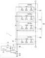
図1は、本実施形態に係る温度測定装置1の概略図である。図1に示される温度測定装置1は電気自動車及びハイブリッド自動車に搭載される組電池100の温度を測定する。このような車載される組電池100は、直列に接続された複数のセル電池150を備えている。本実施形態に係る温度測定装置1は、これらの複数のセル電池150各々の温度を測定することができる。 FIG. 1 is a schematic diagram of a
温度測定装置1は、制御部10と複数のセンサモジュール20とによって主に構成されている。 The
制御部10は、複数のセンサモジュール20に対して一括して電圧を印加するとともに、センサモジュール20から温度の検出信号を入力する回路である。このような制御部10を構成する各要素は、例えば一枚の電子基板に実装されており、車両に搭載された組電池100から離れた位置に設けられている。 The
この制御部10と各センサモジュール20とは、後に詳述する給電ライン30と検出ライン40とによって接続されている。制御部10は、給電ライン30を通じて各センサモジュール20に対して電圧を印加し、検出ライン40を通じて各センサモジュール20の検出信号を入力する。 The
本実施形態に係る制御部10は、マイクロコンピュータ11、変換器12、分圧用抵抗体55及びA/Dコンバータ13の各要素によって構成されている。 The
マイクロコンピュータ11は、例えば、各種演算処理を行うCPU、ブートプログラム等を記憶するROM、演算処理の作業領域となるRAM、プログラムや各種のデータファイルなどを記憶する記憶部(例えばハードディスク)、等を備える。 The
マイクロコンピュータ11は、周波数を様々な値に切り替えて交流電圧を出力ポート111から出力することができる交流電圧供給部としての機能を有する。マイクロコンピュータ11から出力される交流電圧の周波数は可変であるが、振幅はいずれも同じ値である。本実施形態におけるマイクロコンピュータ11から出力される交流電圧は矩形波である。 The
マイクロコンピュータ11の出力ポート111から出力された交流電圧は、変換器12により正弦波の交流電圧に変換され、複数のセンサモジュール20の一次側に繋がる1本の給電ライン30に印加される。複数のセンサモジュール20の二次側は、1本の検出ライン40に繋がっている。 The AC voltage output from the
また、マイクロコンピュータ11は、交流電圧が給電ライン30に印加されるごとに、検出ライン40に流れる信号を、A/Dコンバータ13を介して入力ポート112から入力する。つまり、本実施形態では、マイクロコンピュータ11は、交流電圧供給部と信号入力部とを兼ねており、出力ポート111が交流電圧供給部に相当し、入力ポート112が信号入力部に相当する。マイクロコンピュータ11は検出した信号の振幅に基づいて温度を算出する。 The
変換器12は、入力側がマイクロコンピュータ11の出力ポート111に接続され、出力側が給電ライン30に接続されている。従って、マイクロコンピュータ11は、変換器12を介して給電ライン30に交流電圧を印加する。変換器12は、マイクロコンピュータ11から出力された矩形波の交流電圧を正弦波電圧に変換する。従って、給電ライン30に接続されている各センサモジュール20は正弦波電圧が印加される。なお、マイクロコンピュータ11が交流電圧を正弦波電圧として出力するのであれば、変換器12は必ずしも設置されなくてよい。 The
A/Dコンバータ13は、入力側が検出ライン40に接続され、出力側がマイクロコンピュータ11の入力ポート112に接続されている。A/Dコンバータ13は、検出ライン40を介して流れてきたセンサモジュール20からの信号をA/D変換してマイクロコンピュータ11の入力ポート112へ伝送する。 The A /
検出ライン40は、制御部10において、A/Dコンバータ13に入力されるラインとアースライン50とに分岐している。アースライン50は、制御部10の各要素が実装された電子基板においてアースされている。そして、抵抗値Rの分圧用抵抗体55がアースライン50に接続されている。この分圧用抵抗体55は、複数のセンサモジュール20各々に設けられた複数のサーミスタ23のうちのいずれか1つとともに分圧回路を構成する。 In the
続いて、センサモジュール20について説明する。本実施形態に係るセンサモジュール20は、コンデンサ21、コイル22、及びサーミスタ23が直列に接続された状態で、1枚の基板に実装された構造を有する。このようなセンサモジュール20が、例えば組電池100を構成する複数のセル電池150各々の隙間に配置され、取り付けのための樹脂部材などでセル電池150各々の表面に固定されている。特に、サーミスタ23は、セル電池150における温度の測定部位に接触した状態で取り付けられている。 Next, the
直列に接続されたコンデンサ21とコイル22とによって構成されたLC回路は、簡易なバンドパスフィルタ回路の一例である。バンドパスフィルタ回路は特定の帯域の周波数を選択的に通過させる回路である。周知のごとく、LC回路の通過帯域は、コンデンサ21の静電容量とコイル22のインダクタンスとによって定まる。通過帯域の周波数の交流電圧がLC回路に印加されると、当該LC回路のインピーダンスがゼロに近くなる。従って、入力信号は当該LC回路を通過することができる。これに対して、通過帯域と異なる周波数の交流電圧が印加されると、入力信号は、当該LC回路で減衰するため、実質的に通過することはできなくなる。このように、LC回路を通過する信号は周波数に応じて選択される。 The LC circuit configured by the
本実施形態では、コンデンサ21とコイル22とを直列に接続したLC回路がバンドパスフィルタ回路として採用されているが、このような形態には限られない。例えばコンデンサとコイルとが並列に接続された形態などであってもよい。また、LC回路に限らず、CR回路によって構成されたハイパスフィルタ回路とRC回路によって構成されたローパスフィルタ回路とが組み合わされた回路、或いはオペアンプが用いられたバンドパスフィルタ回路などであってもよい。入力信号が正弦波である必要はなく、矩形波であってもよい場合は制御部10が変換器12を備える必要はない。 In the present embodiment, an LC circuit in which a
サーミスタ23は、例えばNTCサ−ミスタ、又はPTCサーミスタなど、特性に応じて複数の種類が存在する。NTCサーミスタは温度上昇に伴って抵抗値が低下する。また、NTCサーミスタは温度と抵抗値との変化が線形性を有する。一方、PTCサーミスタは、温度上昇に伴って抵抗値が上昇する。PTCサーミスタは高温域での抵抗変化が急峻なので過剰温度測定に適している。本実施形態では、NTCサーミスタがサーミスタ23として採用されるものとする。 There are a plurality of
このようなセンサモジュール20が各セル電池150に対して1つずつ取り付けられている。本実施形態では、センサモジュール20a〜20nが各セル電池150に取り付けられているものとする。一般的にセンサモジュール20の数はセル電池150の数に一致する。 One
各センサモジュール20a〜20nの入力側は給電ライン30に接続されている。より具体的には、給電ライン30と、センサモジュール20a〜20nが備えるコンデンサ21の入力側の端子と、が接続されている。また、各センサモジュール20a〜20nの出力側は検出ライン40に接続されている。より具体的には、各センサモジュール20a〜20nが備えるサーミスタ23a〜23nの出力側の端子と、検出ライン40と、が接続されている。従って、給電ライン30を流れる信号は、コンデンサ21、コイル22、サーミスタ23という順に通過して検出ライン40へと流れる。なお、信号が流れる順序は必ずしも上記形態に限られるものではない。 The input side of each
各センサモジュール20a〜20nは、一次側の給電ライン30と二次側の検出ライン40との間において並列に接続されている。マイクロコンピュータ11が各センサモジュール20a〜20nに電圧を印加する。 Each of the
各センサモジュール20a〜20n相互間において、コイル22a〜22nのインダクタンス及びコンデンサ21a〜21nの静電容量の組合せは各々異なる。従って、各センサモジュール20a〜20nが備えるLC回路は通過帯域がそれぞれ異なる。マイクロコンピュータ11は、各LC回路の通過帯域に対応した周波数の交流電圧を順次切り替えて出力する。従って、給電ライン30を流れる入力信号は、1つのLC回路は通過可能であるが、その他のLC回路は通過不可能となる。なお、LC回路の通過帯域は、LC回路における入力電圧に対する出力電圧の比(利得値)が最大になるときの入力電圧の周波数である共振周波数及びその近傍の周波数を意味する。 The combinations of the inductances of the
センサモジュール20a〜20n各々が備えるサーミスタ23a〜23nは、測定する温度の範囲が同じであるため、同じ特性を有するものが使用される。 The
続いて、本実施形態に係る温度測定装置1で組電池100の温度測定が行われる原理について説明する。 Next, the principle that the temperature of the assembled
マイクロコンピュータ11は、各センサモジュール20a〜20nが有するLC回路の共振周波数を予め記憶している。本実施形態では、各センサモジュール20a〜20nにおけるLC回路の共振周波数をそれぞれ周波数fa〜fnとする。 The
マイクロコンピュータ11は、変換器12を通じて、最初に周波数faの正弦波電圧を各センサモジュール20a〜20nに印加する。 The
周波数faの交流電圧の信号は、センサモジュール20aが備えるLC回路及びサーミスタ23aを通過して検出ライン40に流れる。従って検出ライン40に流れる信号はサーミスタ23aの検出信号である。 The AC voltage signal having the frequency fa flows through the LC circuit and the
しかしながら、その他のセンサモジュール20b〜20nでは、周波数faの交流電圧の信号は、LC回路によって遮断され、無視できる程度でしか通過しない。このように、周波数faの交流電圧が複数のセンサモジュール20a〜20nに印加されると、実質的にサーミスタ23aの検出信号のみが検出ライン40に流れる。そして、検出ライン40を流れる信号は検出ライン40から分岐したアースライン50へと流れる。アースライン50は分圧用抵抗体55を備えているため、周波数faに対応するサーミスタ23aと分圧用抵抗体55とが、分圧回路を構成する。 However, in the other sensor modules 20b to 20n, the AC voltage signal of the frequency fa is blocked by the LC circuit and passes only to a negligible level. As described above, when the AC voltage having the frequency fa is applied to the plurality of
このとき、分圧用抵抗体55を流れる電流は、
I=Vout/(THR+R) ・・・(1)
で表される。なお、(1)式におけるIは電流値、Voutはマイクロコンピュータ11が出力した交流電圧、THRがサーミスタ23の抵抗値、そしてRが分圧用抵抗体55の抵抗値を表している。At this time, the current flowing through the
I = Vout / (THR + R) (1)
It is represented by In Equation (1), I represents a current value, Vout represents an AC voltage output from the
検出ライン40は端部が制御部10に接続されている。従って、マイクロコンピュータ11が検出するサーミスタ23からの検出信号に基づく入力電圧Vinは、
Vin=IR ・・・(2)
で表される。(2)式に(1)式を代入することによって、
Vin=RVout/(THR+R) ・・・(3)
を導くことができる。An end of the
Vin = IR (2)
It is represented by By substituting equation (1) into equation (2),
Vin = RVout / (THR + R) (3)
Can guide you.
マイクロコンピュータ11の出力ポート111から周波数faの交流電圧が出力されることによって、マイクロコンピュータ11の入力ポート112に検出信号が入力され、入力電圧Vinが測定される。従って、マイクロコンピュータ11が、(3)式に基づいて演算することにより、サーミスタ23aの抵抗値が算出される。このサーミスタ23aの抵抗値に基づいて、サーミスタ23aが取り付けられたセル電池150の温度が求められる。 By outputting an alternating voltage of frequency fa from the
続いて、周波数fbの交流電圧がセンサモジュール20a〜20nに出力される。センサモジュール20bは、周波数fbを通過帯域とするLC回路を備えている。このため、主としてサーミスタ23bからの信号のみが検出ライン40に流れ、マイクロコンピュータ11は、その信号に基づいて演算を行うことによりサーミスタ23bが取り付けられているセル電池150の温度を測定する。 Subsequently, an AC voltage having a frequency fb is output to the
このように、マイクロコンピュータ11は、各センサモジュール20a〜20nが備えるLC回路の通過帯域に相当する周波数fa〜fnの交流電圧を、順次切り替えながら給電ライン30を介して各センサモジュール20a〜20nに印加する。この結果、印加された交流電圧の周波数を通過帯域に含むセンサモジュール20が備えるサーミスタ23からの信号が、検出ライン40を介して、マイクロコンピュータ11に入力される。つまり、印加される交流電圧の周波数を切り替えることによって、温度測定に使用されるサーミスタ23の切り替えを行うことができる。 As described above, the
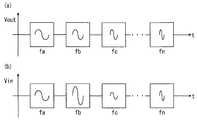
図2には、セル電池150各々の温度が均一である場合の出力電圧Voutと入力電圧Vinとの概略波形が示されている。また、図3には、セル電池150各々の温度が不均一である場合の出力電圧Voutと入力電圧Vinとの概略波形が示されている。具体的に図3では、サーミスタ23bが取り付けられたセル電池150の温度が他のセル電池150の温度よりも高く、サーミスタ23cが取り付けられたセル電池150の温度が他のセル電池150の温度よりも低い場合の出力電圧Voutと入力電圧Vinとの概略波形が示されている。 FIG. 2 shows schematic waveforms of the output voltage Vout and the input voltage Vin when the temperatures of the
図2及び図3に示されるように、所定時間が経過するにつれて周波数がfaからfnへと大きくなり、出力電圧Vout及び入力電圧Vinの1波長分の波形の幅は順に小さくなる。 As shown in FIGS. 2 and 3, the frequency increases from fa to fn as the predetermined time elapses, and the widths of the waveforms of the output voltage Vout and the input voltage Vin for one wavelength decrease in order.
図2(a)には、周波数が所定時間毎に切り替えられながら交流電圧が出力されたときの出力電圧Voutの1波長分の波形が示されている。また、図2(b)には、図2(a)で示される出力電圧Voutによって、マイクロコンピュータ11が検出する入力電圧Vinの1波長分の波形が示されている。サーミスタ23a〜23nが取り付けられた複数のセル電池150各々で温度が均一であるため、図2(b)で示されるように、入力電圧Vinの振幅はいずれも一定である。 FIG. 2A shows a waveform for one wavelength of the output voltage Vout when the AC voltage is output while the frequency is switched every predetermined time. FIG. 2B shows a waveform for one wavelength of the input voltage Vin detected by the
図3(a)には、周波数が所定時間毎に切り替えられながら交流電圧が出力されたときの出力電圧Voutの1波長分の波形が示されている。また、図3(b)には、図3(a)で示される出力電圧Voutによって、マイクロコンピュータ11が検出する入力電圧Vinの1波長分の波形が示されている。 FIG. 3A shows a waveform for one wavelength of the output voltage Vout when the AC voltage is output while the frequency is switched every predetermined time. FIG. 3B shows a waveform for one wavelength of the input voltage Vin detected by the
図3(b)に示されるように、温度が均一であるセル電池150に取り付けられたサーミスタ23a、23d〜23nの入力電圧Vinの振幅は、いずれも同等である。これに対して、サーミスタ23bの入力電圧Vinの振幅は、サーミスタ23a、23d〜23nの入力電圧Vinの振幅よりも大きい。これは、サーミスタ23bが取り付けられたセル電池150の温度が他のセル電池150の温度よりも高くなったため、サーミスタ23bの抵抗値が他のサーミスタ23a、23d〜23nの抵抗値よりも低下したことに起因する。 As shown in FIG. 3B, the amplitudes of the input voltages Vin of the
また、サーミスタ23cの入力電圧Vinの振幅は、サーミスタ23a、23d〜23nの入力電圧Vinの振幅よりも小さい。これは、サーミスタ23cが取り付けられたセル電池150の温度が他のセル電池150の温度よりも低くなったため、サーミスタ23cの抵抗値が他のサーミスタ23a、23d〜23nの抵抗値よりも上昇したことに起因する。 The amplitude of the input voltage Vin of the
マイクロコンピュータ11は振幅を検出することで入力電圧Vinの値を測定する。そして、測定された入力電圧Vinの値が用いられて、上述のように、セル電池150の温度が求められる。 The
なお、検出信号は必ずしも目的とするサーミスタ23からの信号のみを含む場合に限らない。その他のバンドパスフィルタ回路を備えるセンサモジュール20、特に出力電圧の周波数に近い通過帯域を備えるバンドパスフィルタ回路に直列に接続されたサーミスタ23からもわずかに信号が出力される。 The detection signal is not necessarily limited to the case where only the signal from the intended
図4には、バンドパスフィルタ回路毎の出力電圧の周波数fa〜fdに対する利得値が示されている。図4で示されるように、各分布曲線の裾野の部分が、隣り合う分布曲線のピーク値に対応する共振周波数のところまで広がっている。 FIG. 4 shows gain values for the frequencies fa to fd of the output voltage for each bandpass filter circuit. As shown in FIG. 4, the base of each distribution curve extends to the resonance frequency corresponding to the peak value of the adjacent distribution curve.
例えば、周波数faの電圧が印加された場合、周波数faを共振周波数とするバンドパスフィルタ回路から最も大きい信号が出力される。これとともに、周波数faのところまで裾野の部分が広がっている分布曲線で利得値が表されるバンドパスフィルタ回路からも、裾野の部分に対応するわずかな信号が出力される。つまり、検出ライン40を流れる信号は、目的とするサーミスタ23以外のサーミスタ23からの信号も幾分含む場合がある。このため、分布曲線各々の裾野の部分の重なりが小さくなるように、共振周波数の値の間隔は広く設定することが望ましい。これによって分布曲線の重なりを小さくすることができるため、目的としないバンドパスフィルタ回路からの信号の影響を抑えることができる。 For example, when a voltage having a frequency fa is applied, the largest signal is output from a band-pass filter circuit having the frequency fa as a resonance frequency. At the same time, a slight signal corresponding to the bottom portion is also output from the bandpass filter circuit in which the gain value is represented by a distribution curve in which the bottom portion extends to the frequency fa. That is, the signal flowing through the
以上のように、本実施形態に係る温度測定装置1は、マイクロコンピュータ11が、交流電圧の周波数を、各バンドパスフィルタ回路の各々異なる通過帯域の周波数に順次切り替えつつ、センサモジュール20a〜20nに交流電圧を印加する。これによって検出ライン40を流れる信号は、出力された交流電圧の周波数を通過帯域とするバンドパスフィルタ回路に直列接続されたサーミスタ23から出力される。つまり、1本の給電ライン30に印加される交流電圧の周波数が順次切り替えられることによって、1本の検出ライン40を通じて、サーミスタ23各々の信号が個別に検出される。 As described above, in the
また、温度測定装置1においては、複数のサーミスタ23が配置される組電池100の設置場所と制御部10との間に配設される信号線は、1本の給電ライン30及び1本の検出ライン40のみで足りる。従って、温度測定装置1は、サーミスタ23の数と同数の検出ラインが必要となる従来の温度測定装置に比べ、検出ラインの配線スペース及び配線工数が格段に低減される。その効果は、組電池100の温度測定のように、多数の測定部位を含む測定対象の温度が測定される場合に特に顕著となる。 In the
また、本実施形態に係る温度測定装置1では、正弦波電圧が出力されるとともに、各センサモジュール20a〜20nが備えるバンドパスフィルタ回路は、コイル22とコンデンサ21とを直列に接続したLC回路で構成されている。このため、シンプルかつ安価な構成でバンドパスフィルタ回路を実現することができる。 In the
また、サーミスタはすべて同じ特性を有している。このため、測定された電圧値から温度を算出するためのサーミスタの演算処理が容易となる。 All thermistors have the same characteristics. For this reason, thermistor calculation processing for calculating the temperature from the measured voltage value is facilitated.
1 温度測定装置
10 制御部
11 マイクロコンピュータ
20 センサモジュール
21 コンデンサ
22 コイル
23 サーミスタ
30 給電ライン
40 検出ラインDESCRIPTION OF
Claims (3)
Translated fromJapanese複数の前記バンドパスフィルタ回路各々に対して直列に接続された複数のサーミスタと、
直列に接続された前記バンドパスフィルタ回路及び前記サーミスタのセット各々を並列に接続する一次側の給電ライン及び二次側の検出ラインと、
前記給電ラインに対して前記バンドパスフィルタ各々の通過帯域に対応した周波数の交流電圧を順次切り替えて印加する交流電圧供給部と、
周波数の異なる前記交流電圧が前記給電ラインに印加されるごとに前記検出ラインに流れる信号を入力する信号入力部と、
を備える温度測定装置。A plurality of bandpass filter circuits each having a different passband;
A plurality of thermistors connected in series to each of the plurality of bandpass filter circuits;
A power supply line on the primary side and a detection line on the secondary side that connect each of the set of the bandpass filter circuit and the thermistor connected in series in parallel;
An AC voltage supply unit for sequentially switching and applying an AC voltage having a frequency corresponding to a pass band of each of the bandpass filters to the power supply line;
A signal input unit for inputting a signal flowing in the detection line each time the AC voltage having a different frequency is applied to the power supply line;
A temperature measuring device comprising:
前記バンドパスフィルタ回路は、コイルとコンデンサとが直列に接続されたLC回路であり、
前記交流電圧供給部は、それぞれ周波数の異なる複数種類の正弦波電圧を順次切り替えて印加する温度測定装置。The temperature measuring device according to claim 1,
The bandpass filter circuit is an LC circuit in which a coil and a capacitor are connected in series,
The AC voltage supply unit is a temperature measurement device that sequentially switches and applies a plurality of types of sinusoidal voltages having different frequencies.
複数の前記サーミスタは特性が同じである温度測定装置。The temperature measuring device according to claim 1 or 2,
A plurality of thermistors are temperature measuring devices having the same characteristics.
Priority Applications (1)
| Application Number | Priority Date | Filing Date | Title |
|---|---|---|---|
| JP2011089298AJP5545258B2 (en) | 2011-04-13 | 2011-04-13 | Temperature measuring device |
Applications Claiming Priority (1)
| Application Number | Priority Date | Filing Date | Title |
|---|---|---|---|
| JP2011089298AJP5545258B2 (en) | 2011-04-13 | 2011-04-13 | Temperature measuring device |
Publications (2)
| Publication Number | Publication Date |
|---|---|
| JP2012220445A JP2012220445A (en) | 2012-11-12 |
| JP5545258B2true JP5545258B2 (en) | 2014-07-09 |
Family
ID=47272096
Family Applications (1)
| Application Number | Title | Priority Date | Filing Date |
|---|---|---|---|
| JP2011089298AExpired - Fee RelatedJP5545258B2 (en) | 2011-04-13 | 2011-04-13 | Temperature measuring device |
Country Status (1)
| Country | Link |
|---|---|
| JP (1) | JP5545258B2 (en) |
Cited By (1)
| Publication number | Priority date | Publication date | Assignee | Title |
|---|---|---|---|---|
| EP4621368A1 (en) | 2024-03-22 | 2025-09-24 | Volkswagen Ag | Device for determining sensor values |
Families Citing this family (2)
| Publication number | Priority date | Publication date | Assignee | Title |
|---|---|---|---|---|
| JP5805125B2 (en) | 2013-03-18 | 2015-11-04 | 三菱電機株式会社 | Ignition device |
| WO2021199418A1 (en)* | 2020-04-03 | 2021-10-07 | 三菱電機株式会社 | Temperature detecting circuit |
Family Cites Families (5)
| Publication number | Priority date | Publication date | Assignee | Title |
|---|---|---|---|---|
| JPS5129414B1 (en)* | 1970-04-03 | 1976-08-25 | ||
| JPS63245214A (en)* | 1987-03-30 | 1988-10-12 | 住友電気工業株式会社 | temperature monitoring device |
| JPH09318461A (en)* | 1996-05-31 | 1997-12-12 | Satake Eng Co Ltd | Digital cable thermometer |
| US6511478B1 (en)* | 2000-06-30 | 2003-01-28 | Scimed Life Systems, Inc. | Medical probe with reduced number of temperature sensor wires |
| JP2011033359A (en)* | 2009-07-29 | 2011-02-17 | Mitsubishi Materials Corp | Temperature sensor |
- 2011
- 2011-04-13JPJP2011089298Apatent/JP5545258B2/ennot_activeExpired - Fee Related
Cited By (1)
| Publication number | Priority date | Publication date | Assignee | Title |
|---|---|---|---|---|
| EP4621368A1 (en) | 2024-03-22 | 2025-09-24 | Volkswagen Ag | Device for determining sensor values |
Also Published As
| Publication number | Publication date |
|---|---|
| JP2012220445A (en) | 2012-11-12 |
Similar Documents
| Publication | Publication Date | Title |
|---|---|---|
| US9410990B2 (en) | Method and sensor for sensing current in a conductor | |
| CN105452879B (en) | For measuring the device and application thereof of the exchange electric component in direct current electrical circuit | |
| CN103339860B (en) | Capacitive proximity sensor and method for capacitive proximity detection | |
| JP5545258B2 (en) | Temperature measuring device | |
| WO2014118625A1 (en) | Voltage measuring apparatus with temperature abnormality detection function and power conversion apparatus | |
| ES2908033T3 (en) | capacitive measurement system | |
| CN106155435A (en) | High-sensitivity capacitive touch device and operation method thereof | |
| KR20220118437A (en) | High-precision, non-invasive current sensor system | |
| JP6211493B2 (en) | Temperature detection device | |
| CN105092926A (en) | Impedance matching element for voltage and/or current sensing devices | |
| US9625505B2 (en) | Line frequency detector | |
| JP5521578B2 (en) | PM detector | |
| WO2017061036A1 (en) | Impedance measurement device and processing method therefor | |
| CN201331567Y (en) | Detection device | |
| CN108369251B (en) | Reactance measuring device | |
| US10386417B2 (en) | Electronic battery sensor and method for determining an internal resistance of a battery | |
| JP7009025B2 (en) | Voltage measuring device, voltage measuring method | |
| WO2015133212A1 (en) | Voltage measuring apparatus and voltage measuring method | |
| JP7011730B2 (en) | Load impedance tester and measurement method | |
| US10707673B2 (en) | Protection circuit for oscilloscope measurement channel | |
| JP2015179012A (en) | Frequency detection device and measurement device | |
| CN112924744A (en) | Ripple current measuring method and device, computer equipment and coil assembly | |
| TW201405135A (en) | Power testing circuit | |
| JP2016194428A (en) | Battery voltage detector | |
| JP2017538937A (en) | Inductive position determination |
Legal Events
| Date | Code | Title | Description |
|---|---|---|---|
| A621 | Written request for application examination | Free format text:JAPANESE INTERMEDIATE CODE: A621 Effective date:20131004 | |
| A977 | Report on retrieval | Free format text:JAPANESE INTERMEDIATE CODE: A971007 Effective date:20140312 | |
| TRDD | Decision of grant or rejection written | ||
| A01 | Written decision to grant a patent or to grant a registration (utility model) | Free format text:JAPANESE INTERMEDIATE CODE: A01 Effective date:20140415 | |
| A61 | First payment of annual fees (during grant procedure) | Free format text:JAPANESE INTERMEDIATE CODE: A61 Effective date:20140428 | |
| R150 | Certificate of patent or registration of utility model | Ref document number:5545258 Country of ref document:JP Free format text:JAPANESE INTERMEDIATE CODE: R150 | |
| LAPS | Cancellation because of no payment of annual fees |