JP5544907B2 - Structure for gas shower and substrate processing apparatus - Google Patents
Structure for gas shower and substrate processing apparatusDownload PDFInfo
- Publication number
- JP5544907B2 JP5544907B2JP2010023509AJP2010023509AJP5544907B2JP 5544907 B2JP5544907 B2JP 5544907B2JP 2010023509 AJP2010023509 AJP 2010023509AJP 2010023509 AJP2010023509 AJP 2010023509AJP 5544907 B2JP5544907 B2JP 5544907B2
- Authority
- JP
- Japan
- Prior art keywords
- plate
- gas
- screw member
- processing
- elastic body
- Prior art date
- Legal status (The legal status is an assumption and is not a legal conclusion. Google has not performed a legal analysis and makes no representation as to the accuracy of the status listed.)
- Active
Links
Images


Classifications
- C—CHEMISTRY; METALLURGY
- C23—COATING METALLIC MATERIAL; COATING MATERIAL WITH METALLIC MATERIAL; CHEMICAL SURFACE TREATMENT; DIFFUSION TREATMENT OF METALLIC MATERIAL; COATING BY VACUUM EVAPORATION, BY SPUTTERING, BY ION IMPLANTATION OR BY CHEMICAL VAPOUR DEPOSITION, IN GENERAL; INHIBITING CORROSION OF METALLIC MATERIAL OR INCRUSTATION IN GENERAL
- C23C—COATING METALLIC MATERIAL; COATING MATERIAL WITH METALLIC MATERIAL; SURFACE TREATMENT OF METALLIC MATERIAL BY DIFFUSION INTO THE SURFACE, BY CHEMICAL CONVERSION OR SUBSTITUTION; COATING BY VACUUM EVAPORATION, BY SPUTTERING, BY ION IMPLANTATION OR BY CHEMICAL VAPOUR DEPOSITION, IN GENERAL
- C23C16/00—Chemical coating by decomposition of gaseous compounds, without leaving reaction products of surface material in the coating, i.e. chemical vapour deposition [CVD] processes
- C23C16/44—Chemical coating by decomposition of gaseous compounds, without leaving reaction products of surface material in the coating, i.e. chemical vapour deposition [CVD] processes characterised by the method of coating
- C23C16/455—Chemical coating by decomposition of gaseous compounds, without leaving reaction products of surface material in the coating, i.e. chemical vapour deposition [CVD] processes characterised by the method of coating characterised by the method used for introducing gases into reaction chamber or for modifying gas flows in reaction chamber
- C23C16/45563—Gas nozzles
- C23C16/45565—Shower nozzles
- B—PERFORMING OPERATIONS; TRANSPORTING
- B05—SPRAYING OR ATOMISING IN GENERAL; APPLYING FLUENT MATERIALS TO SURFACES, IN GENERAL
- B05B—SPRAYING APPARATUS; ATOMISING APPARATUS; NOZZLES
- B05B1/00—Nozzles, spray heads or other outlets, with or without auxiliary devices such as valves, heating means
- B05B1/14—Nozzles, spray heads or other outlets, with or without auxiliary devices such as valves, heating means with multiple outlet openings; with strainers in or outside the outlet opening
- B05B1/18—Roses; Shower heads
- C—CHEMISTRY; METALLURGY
- C23—COATING METALLIC MATERIAL; COATING MATERIAL WITH METALLIC MATERIAL; CHEMICAL SURFACE TREATMENT; DIFFUSION TREATMENT OF METALLIC MATERIAL; COATING BY VACUUM EVAPORATION, BY SPUTTERING, BY ION IMPLANTATION OR BY CHEMICAL VAPOUR DEPOSITION, IN GENERAL; INHIBITING CORROSION OF METALLIC MATERIAL OR INCRUSTATION IN GENERAL
- C23C—COATING METALLIC MATERIAL; COATING MATERIAL WITH METALLIC MATERIAL; SURFACE TREATMENT OF METALLIC MATERIAL BY DIFFUSION INTO THE SURFACE, BY CHEMICAL CONVERSION OR SUBSTITUTION; COATING BY VACUUM EVAPORATION, BY SPUTTERING, BY ION IMPLANTATION OR BY CHEMICAL VAPOUR DEPOSITION, IN GENERAL
- C23C16/00—Chemical coating by decomposition of gaseous compounds, without leaving reaction products of surface material in the coating, i.e. chemical vapour deposition [CVD] processes
- C23C16/44—Chemical coating by decomposition of gaseous compounds, without leaving reaction products of surface material in the coating, i.e. chemical vapour deposition [CVD] processes characterised by the method of coating
- C23C16/455—Chemical coating by decomposition of gaseous compounds, without leaving reaction products of surface material in the coating, i.e. chemical vapour deposition [CVD] processes characterised by the method of coating characterised by the method used for introducing gases into reaction chamber or for modifying gas flows in reaction chamber
- C—CHEMISTRY; METALLURGY
- C23—COATING METALLIC MATERIAL; COATING MATERIAL WITH METALLIC MATERIAL; CHEMICAL SURFACE TREATMENT; DIFFUSION TREATMENT OF METALLIC MATERIAL; COATING BY VACUUM EVAPORATION, BY SPUTTERING, BY ION IMPLANTATION OR BY CHEMICAL VAPOUR DEPOSITION, IN GENERAL; INHIBITING CORROSION OF METALLIC MATERIAL OR INCRUSTATION IN GENERAL
- C23C—COATING METALLIC MATERIAL; COATING MATERIAL WITH METALLIC MATERIAL; SURFACE TREATMENT OF METALLIC MATERIAL BY DIFFUSION INTO THE SURFACE, BY CHEMICAL CONVERSION OR SUBSTITUTION; COATING BY VACUUM EVAPORATION, BY SPUTTERING, BY ION IMPLANTATION OR BY CHEMICAL VAPOUR DEPOSITION, IN GENERAL
- C23C16/00—Chemical coating by decomposition of gaseous compounds, without leaving reaction products of surface material in the coating, i.e. chemical vapour deposition [CVD] processes
- C23C16/44—Chemical coating by decomposition of gaseous compounds, without leaving reaction products of surface material in the coating, i.e. chemical vapour deposition [CVD] processes characterised by the method of coating
- C23C16/50—Chemical coating by decomposition of gaseous compounds, without leaving reaction products of surface material in the coating, i.e. chemical vapour deposition [CVD] processes characterised by the method of coating using electric discharges
- C23C16/505—Chemical coating by decomposition of gaseous compounds, without leaving reaction products of surface material in the coating, i.e. chemical vapour deposition [CVD] processes characterised by the method of coating using electric discharges using radio frequency discharges
- C23C16/509—Chemical coating by decomposition of gaseous compounds, without leaving reaction products of surface material in the coating, i.e. chemical vapour deposition [CVD] processes characterised by the method of coating using electric discharges using radio frequency discharges using internal electrodes
- C23C16/5096—Flat-bed apparatus
- C—CHEMISTRY; METALLURGY
- C23—COATING METALLIC MATERIAL; COATING MATERIAL WITH METALLIC MATERIAL; CHEMICAL SURFACE TREATMENT; DIFFUSION TREATMENT OF METALLIC MATERIAL; COATING BY VACUUM EVAPORATION, BY SPUTTERING, BY ION IMPLANTATION OR BY CHEMICAL VAPOUR DEPOSITION, IN GENERAL; INHIBITING CORROSION OF METALLIC MATERIAL OR INCRUSTATION IN GENERAL
- C23F—NON-MECHANICAL REMOVAL OF METALLIC MATERIAL FROM SURFACE; INHIBITING CORROSION OF METALLIC MATERIAL OR INCRUSTATION IN GENERAL; MULTI-STEP PROCESSES FOR SURFACE TREATMENT OF METALLIC MATERIAL INVOLVING AT LEAST ONE PROCESS PROVIDED FOR IN CLASS C23 AND AT LEAST ONE PROCESS COVERED BY SUBCLASS C21D OR C22F OR CLASS C25
- C23F1/00—Etching metallic material by chemical means
- C23F1/08—Apparatus, e.g. for photomechanical printing surfaces
- H—ELECTRICITY
- H01—ELECTRIC ELEMENTS
- H01J—ELECTRIC DISCHARGE TUBES OR DISCHARGE LAMPS
- H01J37/00—Discharge tubes with provision for introducing objects or material to be exposed to the discharge, e.g. for the purpose of examination or processing thereof
- H01J37/32—Gas-filled discharge tubes
- H01J37/32431—Constructional details of the reactor
- H01J37/3244—Gas supply means
- H—ELECTRICITY
- H01—ELECTRIC ELEMENTS
- H01L—SEMICONDUCTOR DEVICES NOT COVERED BY CLASS H10
- H01L21/00—Processes or apparatus adapted for the manufacture or treatment of semiconductor or solid state devices or of parts thereof
- H01L21/67—Apparatus specially adapted for handling semiconductor or electric solid state devices during manufacture or treatment thereof; Apparatus specially adapted for handling wafers during manufacture or treatment of semiconductor or electric solid state devices or components ; Apparatus not specifically provided for elsewhere
- H01L21/67005—Apparatus not specifically provided for elsewhere
- H01L21/67011—Apparatus for manufacture or treatment
- H01L21/67098—Apparatus for thermal treatment
Landscapes
- Chemical & Material Sciences (AREA)
- Engineering & Computer Science (AREA)
- Organic Chemistry (AREA)
- Chemical Kinetics & Catalysis (AREA)
- General Chemical & Material Sciences (AREA)
- Materials Engineering (AREA)
- Mechanical Engineering (AREA)
- Metallurgy (AREA)
- Physics & Mathematics (AREA)
- Plasma & Fusion (AREA)
- Analytical Chemistry (AREA)
- Condensed Matter Physics & Semiconductors (AREA)
- General Physics & Mathematics (AREA)
- Manufacturing & Machinery (AREA)
- Computer Hardware Design (AREA)
- Microelectronics & Electronic Packaging (AREA)
- Power Engineering (AREA)
- Plasma Technology (AREA)
- Drying Of Semiconductors (AREA)
- Chemical Vapour Deposition (AREA)
Description
Translated fromJapanese本発明は、処理容器内で基板にガスを供給して処理を行う装置において、基板に対向するように設けられたガスシャワー用の構造体に関する。 The present invention relates to a gas shower structure provided to face a substrate in an apparatus for performing processing by supplying a gas to the substrate in a processing container.
半導体製造プロセスに用いられる装置として、1枚ずつ基板に対して処理を行ういわゆる枚葉式の装置があり、具体的な処理としてはCVD(chemical vapor depositoin)やエッチングなどをプラズマで行うプラズマ処理、熱CVDなどを行う熱処理などが挙げられる。このような処理を行う装置は、通常真空雰囲気内で処理が行われることから、真空チャンバをなす処理容器内に載置台が設けられると共に、この載置台に対向する位置に、処理ガスをシャワー状に基板に供給するためのガスシャワー用の構造体を配置して構成される。 As a device used in a semiconductor manufacturing process, there is a so-called single-wafer type device that performs processing on a substrate one by one. Specific processing includes plasma processing in which CVD (chemical vapor depositoin) or etching is performed with plasma, Examples include heat treatment for performing thermal CVD. Since an apparatus for performing such processing is normally performed in a vacuum atmosphere, a mounting table is provided in a processing container forming a vacuum chamber, and a processing gas is supplied in a shower-like manner at a position facing the mounting table. A gas shower structure for supplying to the substrate is arranged.
図10に真空処理装置の一般的な構造を略解して示しておくと、101は処理容器、102は基板103を載置する載置台、104は処理容器101の天板を兼用するガスシャワーヘッド、105は真空排気を行うための排気管である。ガスシャワーヘッド104は、処理容器101の上面の開口部を図示しないシール部材により気密に塞ぐ蓋部材106とシャワー板107とを備え、ガス導入ポート108から拡散室109を介してシャワー板107に形成されたガス導入孔100から処理ガスがシャワー状に流れるようになっている。 FIG. 10 schematically shows a general structure of a vacuum processing apparatus. 101 is a processing container, 102 is a mounting table on which a
シャワー板107は、互いに異なる材質からなる2枚の板材を積層して構成され、上側に位置するベース板110の材質は、例えばアルミニウム(Al)やステンレススチール(SUS)などの金属が用いられ、下側に位置する天板111の材質は、シリコン(Si)、炭化水素(SiC)、石英などが用いられる。このように2枚のプレートが用いられる理由は、処理雰囲気が真空雰囲気であることからシャワー板107全体については減圧により加わる応力によって変形しない構造とする一方、処理雰囲気に曝される部位については金属汚染のおそれがない構造とするためであり、プラズマ処理を行う場合にはこのような要請に加えて更に耐プラズマ性がある構造とするためである。 The
ベース板110と天板111とを接合する構造としては、例えば図11(a)、(b)に示す構造が知られている。図11(a)の構造は、ベース板110の外縁を天板111の外縁から突出するように形成すると共に、この突出した部位に対向する部分と天板111の下面周縁部を覆う部分とを備えたリング状の金属製のクランプ部材112を用い、ネジ部材113によりベース板110とクランプ部材112とを互いに圧着して両者の間に天板111を挟みこむように構成されている。また図11(b)の構造は、ベース板110と天板111とを、周縁部において天板111側からネジ部材114により固定する構造である。 As a structure for joining the
しかしながらクランプ部材112を用いた構造においては、ネジ部材113によりクランプ部材112を介してベース板110と天板111との圧着が行われるため、設計上クランプ部材112とベース板110との間には隙間が必要となり、この隙間を利用して圧着力をネジトルクとして管理する。このためネジ部材113を締め過ぎず、緩まずといった厳重なネジトルクの管理が必要になり、厳格な操作が要求され、組み立て誤差による性能のばらつき(圧着力のばらつき)が起こる懸念がある。またクランプ部材112の材質としては加工の容易性から金属が用いられるが、天板111とクランプ部材112との材質が互いに異なることから、両者の圧着部位Sにおいて熱膨張の差に基づく擦れが生じて擦れ部位からパーティクルが発生し、処理雰囲気に飛散する懸念がある。
更にまたシャワー板107の温度はプロセスパラメータとして重要であることから、シャワー板107よりも上方側から例えばガスシャワーヘッド104の外側から温度調整が行われるが、クランプ部材112とベース板110との間に隙間が形成されるため、両者の間の熱伝導が悪い。またプラズマ処理においてシャワー板107が電極として用いられる場合には、電気的な導通が悪い。このように熱伝導や電気的な導通が悪いと、シャワー板107とその近傍周囲との間の熱や電界の均一性が悪くなることから、基板の処理の面内均一性に悪影響を及ぼすおそれがある。
なお図11(b)の構造においても、ネジ部材114によりベース板110と天板111との圧着を行っているため、厳重なネジトルクの管理が必要になる。また天板111の材質は上述のようにセラミックスなどが用いられ、ネジ部材114の材質は金属であることから、ネジ孔はベース板110側に設ける必要があり、そのためネジ部材114と天板111との圧着部位Sにおいて熱膨張の差に基づく擦れが生じ、上述と同様の課題がある。更にネジ部材114の頭部をプラズマから保護するために、天板111の周方向に沿って形成されたリング状のカバー部材を用いる場合があるが、カバー部材が大型になると耐プラズマ性の高い材質の選定に制限が生じてくる。またカバー部材と天板111との間には隙間が存在するため、この隙間からプラズマが侵入してネジ部材114を損傷させ、ネジ部材114の緩みや破損の発生の懸念が払拭できない。However, in the structure using the
Furthermore, since the temperature of the
In the structure of FIG. 11B as well, since the
特許文献1には、多数の孔が開いた導体板を、バネ性を有する接電部材を介して支持構造体にネジにより固定する構造が記載されているが、導体板と支持構造体との間の熱伝導や電気的な導通を、バネ性を有する接電部材を介して局所的に行っているため、伝達作用が良好であるとは言い難い。また、ネジとスペーサーとの間及びスペーサーと導体板との間で熱膨張差による擦れが発生し、パーティクルが処理雰囲気に飛散する懸念がある。
更に特許文献2には、高周波電極本体の下側にスパイラル状の金属チューブを介してガスシャワープレートを接合する構造が記載されているが、ガスシャワープレート側からネジ止めを行った場合には図11(b)と同様の問題が起こる。Patent Document 1 describes a structure in which a conductor plate having a large number of holes is fixed to a support structure with a screw via a contact member having a spring property. Since heat conduction and electrical conduction between them are locally performed via a contact member having spring properties, it is difficult to say that the transmission effect is good. Further, there is a concern that friction due to a difference in thermal expansion occurs between the screw and the spacer and between the spacer and the conductor plate, and the particles are scattered in the processing atmosphere.
Further, Patent Document 2 describes a structure in which a gas shower plate is joined to a lower side of a high-frequency electrode body through a spiral metal tube. However, when screwing is performed from the gas shower plate side, FIG. The same problem as in 11 (b) occurs.
本発明はこのような事情の下になされたものであり、その目的は、基板をガスにより処理する処理容器に設けられ、処理雰囲気に面した板状体をベース部材に積層してなるガスシャワー用の構造体において、ベース部材と板状体との圧着力を組み立て誤差に依存せずに適正な大きさに設定することができ、また両者を固定する固定部材と板状体との擦れに基づくパーティクル汚染を防止することができる技術を提供することにある。 The present invention has been made under such circumstances, and an object of the present invention is to provide a gas shower which is provided in a processing container for processing a substrate with a gas, and is formed by laminating a plate-like body facing a processing atmosphere on a base member. In the structure for use, the crimping force between the base member and the plate-like body can be set to an appropriate size without depending on the assembly error, and the friction between the fixing member and the plate-like body for fixing both can be set. It is an object of the present invention to provide a technology capable of preventing particle contamination based on the above.
本発明は、処理容器内に配置された基板と対向するように設けられ、基板を処理するためのガスをシャワー状に供給するためのガスシャワー用の構造体において、
処理雰囲気に面して配置され、多数のガス吐出孔が穿設された板状体と、
この板状体に圧着されて積層され、前記ガス吐出孔に対応する位置にガス吐出孔が穿設されたベース部材と、
前記ベース部材との間に板状体を挟み、板状体側から挿入されてベース部材に螺合し、当該板状体をベース部材に圧着するための金属製のネジ部材と、
前記板状体の処理雰囲気側の面と前記ネジ部材の頭部との間に介在し、ネジ部材が板状体に接近することにより変形して復元力が作用している圧着用の弾性体と、
前記ネジ部材の頭部に被せられ、処理雰囲気によるネジ部材の損傷を防止するための材質からなるカバーと、
前記ネジ部材の頭部の周縁と前記カバーの内面との間に設けられ、ネジ部材とカバーとの熱膨張差を吸収するためのカバー用の弾性体と、を備え、
前記圧着用の弾性体の復元力により板状体がベース部材に圧着され、前記ネジ部材と板状体の処理雰囲気側の面との間には隙間が形成されていることを特徴とする。The present invention provides a gas shower structure for supplying a gas for processing a substrate in a shower-like manner, provided to face a substrate disposed in a processing container.
A plate-like body that is arranged facing the processing atmosphere and has a large number of gas discharge holes,
A base member which is pressure-bonded and laminated to the plate-like body and has a gas discharge hole formed at a position corresponding to the gas discharge hole;
Ametal screw member for sandwiching aplate-like body between thebase member, being inserted from theplate-like body side and screwed into the base member, and crimping the plate-like body to the base member;
An elastic body for pressure bonding, which is interposed between the surface of the plate-like body on the processing atmosphere side andthe head of thescrew member, and is deformed by thescrew member approaching the plate-like body and a restoring force is applied. When,
A cover made of a material that covers the head of the screw member and prevents the screw member from being damaged by the processing atmosphere;
An elastic body for a cover that is provided between the periphery of the head of the screw member and the inner surface of the cover, and absorbs a difference in thermal expansion between the screw member and the cover ;
The plate-like body is pressure-bonded to the base member by the restoring force of thepressure-bonding elastic body , and a gap is formed between thescrew member and the surface of the plate-like body on the processing atmosphere side.
また他の発明は、内部に基板載置部が設けられた処理容器と、前記ガスシャワー用の構造体と、このガスシャワー用の構造体のガス吐出孔に処理ガスを供給するためのガス供給部と、前記処理容器内を真空排気するための真空排気部と、を備えたことを特徴とする基板処理装置である。 According to another aspect of the present invention, there is provided a processing container having a substrate mounting portion therein, a gas shower structure, and a gas supply for supplying a processing gas to a gas discharge hole of the gas shower structure. And a vacuum exhaust unit for exhausting the inside of the processing container.
本発明は、処理雰囲気に面して配置された板状体にベース部材を積層してなり、ガスをシャワー状に供給するためのガスシャワー用の構造体において、板状体の処理雰囲気側に固定部材を配置して当該固定部材とベース部材との間に板状体を挟み込み、そして板状体と固定部材との間に弾性体を介在させて弾性体の復元力により板状体がベース部材に圧着されるようにし、固定部材と板状体との間には隙間を形成するようにしている。従って、ベース部材と板状体との圧着力を組み立て誤差に依存せずに適正な大きさに設定することができ、また両者を固定する固定部材と板状体との擦れに基づくパーティクル汚染を防止することができる。 The present invention is a gas shower structure for laminating a base member on a plate-like body arranged facing a processing atmosphere, and supplying gas in a shower shape, on the processing atmosphere side of the plate-like body. A fixing member is arranged, a plate-like body is sandwiched between the fixing member and the base member, and an elastic body is interposed between the plate-like body and the fixing member, and the plate-like body is made into a base by the restoring force of the elastic body. It is made to press-fit to a member, and it is trying to form a crevice between a fixed member and a plate-shaped object. Accordingly, the pressure-bonding force between the base member and the plate-like body can be set to an appropriate size without depending on assembly errors, and particle contamination based on rubbing between the fixing member and the plate-like body for fixing both can be prevented. Can be prevented.
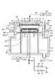
以下、本発明の実施の形態であるガスシャワー用の構造体を備えた基板処理装置の一例について説明する。図1は基板処理装置の全体構造を示し、この基板処理装置はプラズマ処理装置であるRIE(Reactive Ion Etching)プラズマエッチング装置である。まずこの基板処理装置の全体構成について簡単に説明しておくと、図1中の1は、例えばアルミニウムからなる気密な処理容器(真空チャンバー)である。前記処理容器1は、小径の円筒状の上部1aと大径の円筒状の下部1bとからなり、基板である半導体ウエハW(以下、ウエハという)を水平に載置しかつ下部電極として機能する載置台2が設けられている。前記載置台2は例えばアルミニウムで構成されており、絶縁板11を介して導体の支持台12に支持されている。また、前記載置台2の上方の外周には例えばシリコン(Si)で形成されたフォーカスリング13が設けられている。前記支持台12の下方部分はカバー14で覆われている。前記支持台12の外側にはバッフル板15が設けられている。 Hereinafter, an example of a substrate processing apparatus including a gas shower structure according to an embodiment of the present invention will be described. FIG. 1 shows the overall structure of a substrate processing apparatus, which is a RIE (Reactive Ion Etching) plasma etching apparatus which is a plasma processing apparatus. First, the overall configuration of the substrate processing apparatus will be briefly described. Reference numeral 1 in FIG. 1 denotes an airtight processing container (vacuum chamber) made of, for example, aluminum. The processing container 1 includes a small-diameter cylindrical
前記処理容器1の天壁部分は処理容器1内に処理ガスを導入するためのガス供給部であるガスシャワーヘッド16として構成されている。ガスシャワーヘッド16は、処理容器1の上面開口部を塞ぐ例えばアルミニウムからなる蓋部材17と、この蓋部材の下方側にガスの拡散空間を介して配置された、本発明の実施の形態に相当するガスシャワー用の構造体3とを備えている。このガスシャワー用の構造体3は、後で詳述するが、ベース板31と天板32とを積層してなり、多数のガス吐出孔33が形成されたシャワー板30と、ベース板31と天板32とを互いに圧着して固定するためのネジ部材4と、を備えている。 The top wall portion of the processing container 1 is configured as a
ガスシャワーヘッド16は、その上部にガス導入ポート18が設けられると共に、その内部にはガスが拡散するための拡散空間19が形成されている。前記ガス導入ポート18にはガス供給管181が接続されており、このガス供給管181の他端には処理ガスを供給するためのガス供給系182が接続されている。
シャワー板30は、上部電極として機能し、下部電極として機能する載置台2と平行に対向して設けられ、これらにより一対の平行平板電極を構成している。前記処理容器1の下部1bの底壁には、排気ポート21が形成されており、この排気ポート21には真空ポンプ22が接続されている。図1中、23はゲートバルブ24により開閉される搬入出口である。The
The
前記載置台2には、整合器28及び25を介して夫々プラズマ形成用の第1の高周波電源26及びイオン引き込み用の第2の高周波電源27が接続されている。また載置台2の表面部には、直流電源29により駆動され、ウエハWを吸着保持するための静電チャック201が設けられている。前記載置台2の内部には、冷却室202が設けられており、この冷却室202には、冷媒が冷媒導入管203を介して導入され冷媒排出管204から排出されて循環し、その冷熱が載置台2を介してウエハWに対して伝熱され、これによりウエハWの処理面が所望の温度に制御される。更に図1中、205はガス導入機構であり、このガス導入機構205は、伝熱用ガスをガス供給ライン206を介して静電チャック201の表面とウエハWの裏面との間に導入するためのものである。 A first high-
前記処理容器1の上部1aの周囲には、上下電極の間の処理空間の周辺部のみに磁場が形成され、処理空間へプラズマを閉じ込める作用を得るために、搬入出口23を挟んで2つのマルチポールリング磁石25a,25bが配置されている。 Around the
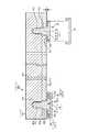
次に、ガスシャワー用の構造体3の構成について詳細に説明する。ガスシャワー用の構造体3は、図1および図2に示すように円形のベース板31の下面側に当該ベース板31と同径の円形の天板32が積層されている。これらベース板31及び天板32は、夫々特許請求の範囲のベース部材及び板状体に相当する。ベース板31は、金属例えばアルミニウムからなり、厚さは例えば20mmである。天板32の材質としては、例えば耐プラズマ性の大きい材料例えば石英、炭化珪素(SiC)または窒化珪素などのセラミックスが用いられるか、あるいはプラズマにより叩かれて成分が飛散しても半導体装置への悪影響が小さいシリコンなどが好ましいものとして用いられる。また天板32の厚さは例えば3〜10mmである。ベース板31及び天板32には、互いに対応する位置に多数のガス吐出孔33が穿設されている。なお符号の煩雑化をさけるためにベース板31及び天板32のいずれのガス吐出孔についても共通の符号「33」を割り当てる。また説明の便宜上、ベース板31及び天板32の積層体をシャワー板30と呼ぶことにする。このシャワー板30によれば、減圧による応力が加わったときの変形防止の役割と処理雰囲気に曝されることによりパーティクルや重金属が飛散することを防止する役割とを、夫々ベース板31と天板32とに分担させることができる。 Next, the structure of the
ガス吐出孔33のレイアウトについては、シャワー板30の中心を中心とする多数の同心円に沿って形成するパターン、マトリックス状に形成するパターンなどが採用される。このようにシャワー板30にガス吐出孔33を形成することで拡散空間19により拡散したガスがシャワー状に処理雰囲気に流れることになる。 For the layout of the gas discharge holes 33, a pattern formed along a number of concentric circles centering on the center of the
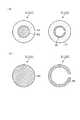
これらベース板31及び天板32は、天板32の外縁部(外縁の近傍領域)において周方向に等間隔な複数箇所にて、固定部材である例えば金属製のネジ部材4が天板32の下面側から挿入され、ベース板31のネジ孔34と螺合している。図3は、天板32をネジ部材4によりベース板31に固定した状態を下方側から見た図であり、この例ではネジ部材4による固定箇所は8箇所とされている。 The
ネジ部材4は、図2及び図4に示すように、頭部41と軸部42とからなり、頭部41は、大径の円形状の平板部41a(図2の右側参照)と、この平板部41の中央部において軸部42側に突出し、平板部41aよりは小径でかつ軸部42よりは大径である円筒部41bとからなる。そして天板32には、ネジ部材4の円筒部41bよりも少し口径の大きい透孔35が形成されており、ネジ部材4は、ベース板31のネジ孔34と螺合したときに、円筒部41bが天板32の透孔35内に収まることとなる。また円筒部41bの軸部42側のリング状の面45は、ネジ部材4を締めていったときに、前記透孔35内に露出しているベース板31の下面に当接するいわば停止面として機能する。 As shown in FIGS. 2 and 4, the
ネジ部材4の頭部41の平板部41aにおける軸部42側の面(天板32に対向している面)には、図2及び図4に示すように軸部42を囲むようにリング状に溝43が形成されると共に、この溝43の外側には、当該溝43よりも深く外縁部を切り欠いて形成された切り欠き部44が形成されている。 The surface of the
そして第1の溝43には、第1の溝43に対応して形成されたリング状の圧着用の弾性体51が嵌合されている。この弾性体51は、変形していないときに溝43から飛び出す大きさに形成されており、ネジ部材4を締め付けて頭部41が天板32に接近していったときに頭部41の平板部41aと天板32との間に挟まれて潰されて変形し、その復元力により天板32がベース板31側に押圧されて天板32とベース板31とが互いに圧着された状態で固定される。従ってネジ部材4が締め付け終わったときには、ネジ部材4の頭部41の平板部41aと天板32との間には、隙間が形成される。 The
この例では、適切な締め付け状態になったときにネジ部材4における円筒部41bの停止面(リング状の面)45がベース板31の下面に当たってそれ以上ベース板31内に入り込めないようにネジ部材4の各部の寸法が設定されているので、ネジ部材4の停止面45がベース板31に当たるまで締め付けを行うことで、常に適切な締め付け状態つまり天板32とベース板31との適切な圧着力が得られる。 In this example, the
図2の右側に示すように前記隙間の寸法Dは、処理雰囲気からのプラズマの侵入を抑えて、弾性体51が処理雰囲気この例ではプラズマに接触して損傷することをできるだけ避けるために、例えば0.2mm以下であることが好ましい。この点からすれば当該隙間は、できるだけ小さいほうが好ましいが、天板32がプラズマにより加熱されたときにネジ部材4と天板32との間の熱膨張の程度が異なるため、この熱膨張差により両者が擦れない程度の隙間を確保することが必要である。 As shown on the right side of FIG. 2, the dimension D of the gap suppresses the intrusion of plasma from the processing atmosphere, and in order to avoid damage to the
以上のようにこの例ではネジ部材4はベース板31との間に天板32を挟み、当該天板32をベース板31に圧着するための固定部材として機能していることになる。
ネジ部材4の頭部41は、軸部42とは反対側からカバー(キャップ)6が被せられており、このカバー6は、内周面が底に向かう程広がる形状に構成されている。このため、リング状のカバー用の弾性体52を前記切り欠き部44に嵌めこみ、カバー6を当該弾性体52の復元力に抗して被せることにより、カバー6が自重で脱落することなく頭部41に装着される。なおカバー6の底面と頭部41を図示しない接着層により接着するようにしてもよい。この弾性体52は、ネジ部材4とカバー6との熱膨張差を吸収する役割を持つ共に、プラズマが頭部41の頂面(図2の状態では下面)に回り込むのを抑え、頭部41及び前記接着層(接着層がある場合)を保護する役割を持っている。カバー6の材質としては、処理雰囲気に対して劣化、損傷が起こりにくい材質、この例では耐プラズマ性の大きい材質が好ましく、例えば石英、炭化珪素あるいは窒化珪素などのセラミックスが用いられる。As described above, in this example, the
A head (41) of the screw member (4) is covered with a cover (cap) 6 from the side opposite to the shaft portion (42), and the cover (6) is configured so as to expand toward the bottom of the inner peripheral surface. For this reason, an
ここで前記弾性体51、52の構造としては、表面においてプラズマに対する耐性が大きいこと、熱や経時変化によって復元力(反力)が低下しにくいこと、接触する相手材に傷をつけにくく、表面摩擦抵抗が小さい構造とすることが好ましい。なおプラズマとは、イオン、ラジカルなどの活性種群を指している。弾性体51、52の構造の具体例について図5に示しておく。図5(a)は、Oリング53を芯材としてこのOリング53の周囲を例えばフッ素樹脂(例えば商品名「テフロン」(登録商標))により被覆して被覆層54として形成したものである。図5(b)は例えば材質がステンレス系素材からなる金属パイプに長さ方向にスリットを形成して、横断面で見たときに一箇所が切り欠かれた構造の金属スプリング55を芯材とし、この金属スプリング55の周囲を例えばフッ素樹脂により被覆して被覆層54として形成したものである。これらの構造は、プラズマを用いたプロセスに有効である。図5(c)は前記Oリング53をそのまま弾性体として用いたものであり、プラズマに対する耐性を必要としない場合に選択できる構造の一つである。図5(d)は金属スプリング55をそのまま弾性体として用いたものであり、強い復元力が要求される場合に有効である。 Here, the structure of the
次に上述のプラズマ処理装置の作用について述べる。先ず、ゲートバルブ24を開いてウエハWを搬入出口23から処理容器1内に搬入し、載置台2に載置して静電チャック201によりウエハWを静電吸着した後、真空ポンプ22により排気ポート21を介して処理容器1内を所定の真空度まで排気する。そして処理ガス供給系182から処理ガス例えばフッ素(F)等がガス供給配管181、ガス導入ポート18を介してガスシャワーヘッド16の拡散空間19に至り、ガス吐出孔33から処理雰囲気に吐出される。そして処理容器1内のガス圧力を所定のプロセス圧力(真空度)にし、その状態で第1の高周波電源26から載置台2に例えば100MHzの高周波電力を供給し、載置台2及び天板32の間(処理雰囲気)に高周波電界を形成する。 Next, the operation of the above plasma processing apparatus will be described. First, the
また第2の高周波電源27からは、プラズマのイオンエネルギーをコントロールするために例えば3.2MHzの高周波電力が供給される。また処理雰囲気にはダイポールリング磁石25a,25bにより水平磁界が形成されているので、ウエハWが存在する電極間の処理空間には直交電磁界が形成され、これによって生じた電子のドリフトによりマグネトロン放電が形成される。そしてこのマグネトロン放電により処理ガスがプラズマ化し、このプラズマによりウエハWの表面に形成された所定の膜がエッチングされる。 Further, from the second high
上述の実施の形態では、ベース板31に天板32を積層して固定する構造において、ベース板31側からネジ部材4を挿入して天板32に螺合すると共に、ネジ部材4の頭部41と天板32との間に弾性体51を介在させてこの弾性体51の復元力によりベース板31と天板32との圧着を行うようにしている。このため、弾性体51が介在しない場合に比べてネジ部材4のトルク管理が容易になり、ベース板31と天板32との圧着力を組み立て誤差に依存せずに適正な大きさに設定することができる。また既述のように適切な締め付け状態になったときに
ネジ部材4の停止面45がベース板31の下面に当たるように各部の寸法を設定しておくことにより、トルク管理は実質不要になり、より一層組み立てが容易になり、前記圧着力が常に予定としている大きさに揃うようになる。また弾性体51の復元力によりネジ部材4が下側に押されることから、ネジ部材4の緩みが抑えられる。In the above-described embodiment, in the structure in which the
更に弾性体51により前記圧着が達成されるのでネジ部材4の頭部41と天板32との間には隙間が形成されるので、両者の熱膨張差に基づく部材間の擦れを防止でき、擦れによるパーティクルの発生を防止できる。また、弾性体51の少なくとも表面をフッ素樹脂等の摩擦係数の小さな材質とすることで、一層擦れによるパーティクルの発生を防止できる。また、前記隙間が熱膨張により拡大したとしても、弾性体51の介在によりプラズマがネジ部材4の軸部42側に侵入することが防止される。またネジ部材4がカバー6により覆われていることから、処理雰囲気とネジ部材4との接触が抑えられ、しかもカバー6がネジ部材4ごとに設けられていることから、天板32の全周に沿ってカバーをリング状に設ける場合に比べてはるかに小型であり、そのため材質の選定の自由度が大きい。更に既述済みであるが、カバー6とネジ部材4との間にカバー用の弾性体52を介在させていることから、ネジ部材4側に入り込もうとするプラズマがこの弾性体52により阻止され、またカバー6とネジ部材4との熱膨張差に基づく擦れもこの弾性体52の介在により防止できる。 Furthermore, since the pressure bonding is achieved by the
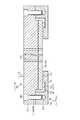
本発明のガスシャワー構造体の他の実施の形態について図6及び図7を参照しながら説明する。この実施の形態では、シャワー板30の外縁部の下面側に、シャワー板30の全周に沿ってリング状に形成されたクランプ部材7が設けられている。ベース板31の外縁部は天板32の外縁より突出した突出部分311として構成されており、この突出部分311は天板32に積層されている部分よりも少し厚さが小さく形成されており、従ってその下面は天板32の上面よりも上方側に位置している。 Another embodiment of the gas shower structure of the present invention will be described with reference to FIGS. In this embodiment, a
クランプ部材7は、天板32の外縁部と対向する内側部分71と、ベース板31の突出部分311の下面と対向して接する外側部分72とからなる。内側部分71において、内縁から例えば20mm外側に寄った位置には、当該クランプ部材7の全周に沿ってリング状に溝73が形成されていると共に、この溝73よりも内縁側の部位の表面は、天板32との間に僅かな隙間を介して対向する水平面74として形成されている。そして前記クランプ部材7の溝73内には、リング状の圧着用の弾性体75が設けられると共に、ベース板31の突出部分311の上面側からネジ部材8が挿入され、クランプ部材7の外側部分72のネジ孔81に螺合している。このネジ部材8による固定部位は、シャワー板30の周方向に沿って等間隔に複数例えば先の実施の形態のように例えば8箇所に形成されている。 The
ネジ部材8の締め付けによりクランプ部材7がシャワー板30側に接近し、これにより弾性体75が押しつぶされて変形する。このためこの弾性体75の復元力により天板32がベース板31に圧着されることになる。クランプ部材7の外側部分72の厚さ及び溝73の深さは、ベース板31の突出部分311とクランプ部材7の外側部分72とが接触した状態において、弾性体75の復元力(反力)によりベース板31及び天板32の圧着力が適切になるように設定されている。従ってネジ部材8を締め、ベース板31とクランプ部材7とが接触した後、この接触を確実にするために少しトルクをかけることでベース板31及び天板32の圧着力を適切なものにできるが、予めこの圧着力が適切になるときにネジ部材8の頭部80の下面(停止面)がベース板31に当たるように各部の寸法を設定しておくようにしてもよい。なお弾性体75の材質、構造については先の実施の形態で記載したものと同じものを用いることができる。 When the
シャワー板30よりも上方側の例えば処理容器1の壁部には、温度調整機構が設けられていて、ベース板31を介して天板32の温度がプロセスに適切な温度となるように調整されていることから、クランプ部材7についても適切な温度に調整されていることが好ましい。またクランプ部材7においても当該クランプ部材7を介してベース板31に高周波が流れることが均一性の高い電界を形成するために好ましい。従ってこの実施の形態では、クランプ部材7とベース板31とが隙間無く接していることから、このような要請、即ち両者の間で良好な熱伝導と電気的な接触とが達成される。このため両者の間で熱膨張の差が発生しないことが望ましく、この観点からクランプ部材7の材質はベース板31と同じ材質、この例ではアルミニウムが用いられている。 A temperature adjusting mechanism is provided, for example, on the wall of the processing container 1 above the
またクランプ部材7の内側部分74の水平面部74と天板32との隙間は、プラズマの侵入を抑えて弾性体の劣化を抑える観点から、例えば0.1から1mmが好ましく、更には0.2mm以下が好ましい。更に内側部分71の内縁から溝73までの距離は例えば10mm以上が好ましく、この例では20mmに設定されている。この例では、特許請求の範囲の固定部材は、クランプ部材7とネジ部材8とから構成される。 Further, the clearance between the
このような実施の形態においても、クランプ部材7と天板32との間に弾性体75を介在させてこの弾性体75の復元力によりベース板31と天板32との圧着を行うようにしている。このため、弾性体75が介在しない場合に比べてネジ部材4のトルク管理が容易になり、ベース板31と天板32との圧着力を組み立て誤差に依存せずに適正な大きさに設定することができる。またクランプ部材7と天板32とは材質が異なるが、両者の間には隙間が形成されているため、熱膨張差に基づく擦れが発生せず、従ってパーティクルが処理雰囲気に飛散することを防止できる。 Also in such an embodiment, the
なお図8及び図9に示すように、クランプ部材7の内側部分を全周に設けずに周方向に間隔をおいて設け、弾性体75を収納する溝73については凹部として構成し、弾性体75はこの溝(凹部)73に収まる形状に構成するようにしてもよい。この例における符号について、図6及び図7に対応する部位に関しては同じ符号を用いている。
また本発明は、プラズマ処理装置に適用されることに限らず、プラズマを用いない処理例えば熱CVDなどを行う装置であってもよい。また処理雰囲気は減圧雰囲気でなくとも加圧雰囲気であってもよい。As shown in FIGS. 8 and 9, the inner part of the
The present invention is not limited to being applied to a plasma processing apparatus, and may be an apparatus that performs processing that does not use plasma, such as thermal CVD. Further, the processing atmosphere may be a pressurized atmosphere instead of a reduced pressure atmosphere.
1 処理容器
16 ガスシャワーヘッド
19 拡散空間
2 載置台
3 ガスシャワー構造体
30 シャワー板
31 ベース板
32 天板
33 ガス吐出孔
34 ネジ孔
4 ネジ部材
41 ネジ部材の頭部
42 ネジ部材の軸部
51 圧着用の弾性体
52 カバー用の弾性体
6 カバー
7 クランプ部材
71 内側部分
72 外側部分
73 溝
75 弾性体
8 ネジ部材DESCRIPTION OF SYMBOLS 1
Claims (6)
Translated fromJapanese処理雰囲気に面して配置され、多数のガス吐出孔が穿設された板状体と、
この板状体に圧着されて積層され、前記ガス吐出孔に対応する位置にガス吐出孔が穿設されたベース部材と、
前記ベース部材との間に板状体を挟み、板状体側から挿入されてベース部材に螺合し、当該板状体をベース部材に圧着するための金属製のネジ部材と、
前記板状体の処理雰囲気側の面と前記ネジ部材の頭部との間に介在し、ネジ部材が板状体に接近することにより変形して復元力が作用している圧着用の弾性体と、
前記ネジ部材の頭部に被せられ、処理雰囲気によるネジ部材の損傷を防止するための材質からなるカバーと、
前記ネジ部材の頭部の周縁と前記カバーの内面との間に設けられ、ネジ部材とカバーとの熱膨張差を吸収するためのカバー用の弾性体と、を備え、
前記圧着用の弾性体の復元力により板状体がベース部材に圧着され、前記ネジ部材と板状体の処理雰囲気側の面との間には隙間が形成されていることを特徴とするガスシャワー用の構造体。In a gas shower structure for supplying a gas for processing a substrate in a shower shape provided to face a substrate disposed in the processing container,
A plate-like body that is arranged facing the processing atmosphere and has a large number of gas discharge holes,
A base member which is pressure-bonded and laminated to the plate-like body and has a gas discharge hole formed at a position corresponding to the gas discharge hole;
Ametal screw member for sandwiching aplate-like body between thebase member, being inserted from theplate-like body side and screwed into the base member, and crimping the plate-like body to the base member;
An elastic body for pressure bonding, which is interposed between the surface of the plate-like body on the processing atmosphere side andthe head of thescrew member, and is deformed by thescrew member approaching the plate-like body and a restoring force is applied. When,
A cover made of a material that covers the head of the screw member and prevents the screw member from being damaged by the processing atmosphere;
An elastic body for a cover that is provided between the periphery of the head of the screw member and the inner surface of the cover, and absorbs a difference in thermal expansion between the screw member and the cover ;
Gas plate-shaped body by the restoring force of theelastic body for thecrimp is crimped to the base member, characterized in that gap is formed between thescrew member and the surface of the treatment atmosphere side of the plate-like body Shower structure.
前記基板載置部に対向して設けられた請求項1ないし5のいずれか一項に記載のガスシャワー用の構造体と、
このガスシャワー用の構造体のガス吐出孔に処理ガスを供給するためのガス供給部と、
前記処理容器内を真空排気するための真空排気部と、を備えたことを特徴とする基板処理装置。A processing container provided with a substrate mounting portion therein;
The gas shower structure according to any one of claims 1 to5 , wherein the gas shower structure is provided to face the substrate mounting portion.
A gas supply unit for supplying a processing gas to the gas discharge holes of the gas shower structure;
A substrate processing apparatus comprising: an evacuation unit for evacuating the inside of the processing container.
Priority Applications (5)
| Application Number | Priority Date | Filing Date | Title |
|---|---|---|---|
| JP2010023509AJP5544907B2 (en) | 2010-02-04 | 2010-02-04 | Structure for gas shower and substrate processing apparatus |
| KR1020110006962AKR101684997B1 (en) | 2010-02-04 | 2011-01-24 | Gas shower structure and substrate processing apparatus |
| CN2011100347600ACN102191502B (en) | 2010-02-04 | 2011-01-31 | Gas shower structure and substrate processing apparatus |
| TW100103804ATWI525697B (en) | 2010-02-04 | 2011-02-01 | Gas spray construction and substrate processing device |
| US13/020,104US9550194B2 (en) | 2010-02-04 | 2011-02-03 | Gas shower structure and substrate processing apparatus |
Applications Claiming Priority (1)
| Application Number | Priority Date | Filing Date | Title |
|---|---|---|---|
| JP2010023509AJP5544907B2 (en) | 2010-02-04 | 2010-02-04 | Structure for gas shower and substrate processing apparatus |
Publications (2)
| Publication Number | Publication Date |
|---|---|
| JP2011165718A JP2011165718A (en) | 2011-08-25 |
| JP5544907B2true JP5544907B2 (en) | 2014-07-09 |
Family
ID=44340601
Family Applications (1)
| Application Number | Title | Priority Date | Filing Date |
|---|---|---|---|
| JP2010023509AActiveJP5544907B2 (en) | 2010-02-04 | 2010-02-04 | Structure for gas shower and substrate processing apparatus |
Country Status (5)
| Country | Link |
|---|---|
| US (1) | US9550194B2 (en) |
| JP (1) | JP5544907B2 (en) |
| KR (1) | KR101684997B1 (en) |
| CN (1) | CN102191502B (en) |
| TW (1) | TWI525697B (en) |
Families Citing this family (19)
| Publication number | Priority date | Publication date | Assignee | Title |
|---|---|---|---|---|
| JP5992288B2 (en)* | 2012-10-15 | 2016-09-14 | 東京エレクトロン株式会社 | Gas introduction apparatus and inductively coupled plasma processing apparatus |
| JP6379550B2 (en)* | 2014-03-18 | 2018-08-29 | 東京エレクトロン株式会社 | Deposition equipment |
| JP6756853B2 (en)* | 2016-06-03 | 2020-09-16 | アプライド マテリアルズ インコーポレイテッドApplied Materials,Incorporated | Effective and new design for low particle count and better wafer quality by diffusing the flow inside the chamber |
| WO2018041318A1 (en)* | 2016-08-30 | 2018-03-08 | Stiesdal Offshore Technologies A/S | Protection system for a threaded fastener a method for installation, inspection and maintenance of such protection system |
| US10763141B2 (en)* | 2017-03-17 | 2020-09-01 | Applied Materials, Inc. | Non-contact temperature calibration tool for a substrate support and method of using the same |
| TWI633585B (en)* | 2017-03-31 | 2018-08-21 | 漢民科技股份有限公司 | Combination of gas injector and top plate for semiconductor process and film forming device |
| KR101979222B1 (en)* | 2017-12-22 | 2019-05-17 | 인베니아 주식회사 | Assembly for generating plasma and apparatus for processing substrate having the same |
| JP7182916B2 (en)* | 2018-06-26 | 2022-12-05 | 東京エレクトロン株式会社 | Plasma processing equipment |
| CN111383880B (en)* | 2018-12-27 | 2023-03-31 | 中微半导体设备(上海)股份有限公司 | Plasma processor's mounting structure and corresponding plasma processor |
| CN111385955B (en)* | 2018-12-28 | 2022-08-23 | 中微半导体设备(上海)股份有限公司 | Plasma processor's mounting structure and corresponding plasma processor |
| JP6973429B2 (en)* | 2019-02-21 | 2021-11-24 | 株式会社豊田中央研究所 | Plasma device |
| US20220336194A1 (en)* | 2019-09-17 | 2022-10-20 | Tokyo Electron Limited | Plasma processing apparatus |
| TWI857147B (en)* | 2019-10-04 | 2024-10-01 | 美商應用材料股份有限公司 | Gas distribution assembly mounting for fragile plates to prevent breakage |
| CN112922935B (en)* | 2019-12-05 | 2023-06-30 | 中微半导体设备(上海)股份有限公司 | Connection structure and plasma processing apparatus |
| US12068137B2 (en)* | 2020-09-25 | 2024-08-20 | Applied Materials, Inc. | Thread profiles for semiconductor process chamber components |
| JP7637561B2 (en) | 2020-10-15 | 2025-02-28 | 東京エレクトロン株式会社 | Fastening structure, plasma processing apparatus and fastening method |
| TW202232564A (en)* | 2020-10-15 | 2022-08-16 | 日商東京威力科創股份有限公司 | Fastening structure, plasma processing apparatus, and fastening method |
| CN116313717A (en)* | 2021-12-21 | 2023-06-23 | 中微半导体设备(上海)股份有限公司 | A flexible installation connection structure and corresponding plasma processor |
| KR20240065990A (en)* | 2022-11-07 | 2024-05-14 | 삼성전자주식회사 | Substrate processing apparatus and substrate processing method |
Family Cites Families (32)
| Publication number | Priority date | Publication date | Assignee | Title |
|---|---|---|---|---|
| FR661237A (en)* | 1928-01-20 | 1929-07-23 | Advanced bolt and nut clamping device | |
| US3175454A (en)* | 1963-11-26 | 1965-03-30 | Morse Milton | Threaded sealing devices having o-ring recess of asymmetrical configuration |
| US4784555A (en)* | 1985-09-09 | 1988-11-15 | Cantrell Roger M | Protective and ornamental cover for nuts and bolts |
| JP3165322B2 (en)* | 1994-03-28 | 2001-05-14 | 東京エレクトロン株式会社 | Decompression container |
| US5676757A (en)* | 1994-03-28 | 1997-10-14 | Tokyo Electron Limited | Decompression container |
| JPH08250465A (en)* | 1995-03-07 | 1996-09-27 | Souzou Kagaku:Kk | Electrode cover for semiconductor plasma processing equipment |
| US5569356A (en)* | 1995-05-19 | 1996-10-29 | Lam Research Corporation | Electrode clamping assembly and method for assembly and use thereof |
| US5791848A (en)* | 1997-04-24 | 1998-08-11 | Mcgard, Inc. | Structure for converting standard drive fastener to security fastener |
| JP3480271B2 (en)* | 1997-10-07 | 2003-12-15 | 東京エレクトロン株式会社 | Shower head structure of heat treatment equipment |
| KR100258984B1 (en)* | 1997-12-24 | 2000-08-01 | 윤종용 | Dry etching apparatus |
| US6073577A (en)* | 1998-06-30 | 2000-06-13 | Lam Research Corporation | Electrode for plasma processes and method for manufacture and use thereof |
| US6916399B1 (en)* | 1999-06-03 | 2005-07-12 | Applied Materials Inc | Temperature controlled window with a fluid supply system |
| JP4387008B2 (en) | 1999-11-08 | 2009-12-16 | キヤノンアネルバ株式会社 | High frequency electrode device for substrate processing equipment |
| TWI224815B (en)* | 2001-08-01 | 2004-12-01 | Tokyo Electron Ltd | Gas processing apparatus and gas processing method |
| US20040157035A1 (en)* | 2003-02-10 | 2004-08-12 | Guizzetti Allen R. | Low permeation gaskets |
| JP2004356509A (en) | 2003-05-30 | 2004-12-16 | Renesas Technology Corp | Plasma treating apparatus |
| EP1667217A1 (en)* | 2003-09-03 | 2006-06-07 | Tokyo Electron Limited | Gas treatment device and heat readiting method |
| JP2005276850A (en)* | 2004-03-22 | 2005-10-06 | Hitachi Kokusai Electric Inc | Substrate processing equipment |
| KR20050116230A (en)* | 2004-06-07 | 2005-12-12 | 엘지.필립스 엘시디 주식회사 | Plasma enhanced chemical vapor deposition apparutus |
| US20060108069A1 (en)* | 2004-11-19 | 2006-05-25 | Samsung Electronics Co., Ltd. | Plasma reaction chamber and captive silicon electrode plate for processing semiconductor wafers |
| JP2007067208A (en)* | 2005-08-31 | 2007-03-15 | Shin Etsu Chem Co Ltd | Shower plate for plasma processing apparatus and plasma processing apparatus |
| GB0603318D0 (en)* | 2006-02-20 | 2006-03-29 | Boc Group Plc | Seal |
| JP2007273637A (en)* | 2006-03-30 | 2007-10-18 | Tokyo Electron Ltd | Microwave plasma treatment apparatus and its manufacturing method, and plasma treatment method |
| CN101529561A (en)* | 2006-10-16 | 2009-09-09 | 朗姆研究公司 | Quartz guard ring |
| JP2008192513A (en)* | 2007-02-06 | 2008-08-21 | Sekisui Chem Co Ltd | Plasma processing device |
| JP2009021220A (en)* | 2007-06-11 | 2009-01-29 | Tokyo Electron Ltd | Plasma processing apparatus, antenna, and method of using plasma processing apparatus |
| US20080303744A1 (en) | 2007-06-11 | 2008-12-11 | Tokyo Electron Limited | Plasma processing system, antenna, and use of plasma processing system |
| JP5019256B2 (en)* | 2007-07-06 | 2012-09-05 | 三菱マテリアル株式会社 | Convex silicon electrode plate for plasma etching |
| JP2009191979A (en)* | 2008-02-15 | 2009-08-27 | Onchi Seibyo Kk | Capped screw and covering cap |
| JP5285403B2 (en)* | 2008-04-15 | 2013-09-11 | 東京エレクトロン株式会社 | Vacuum container and plasma processing apparatus |
| CN101296553B (en)* | 2008-06-25 | 2011-01-12 | 北京北方微电子基地设备工艺研究中心有限责任公司 | Plasma processing apparatus |
| CN201322037Y (en)* | 2008-11-27 | 2009-10-07 | 武汉鼎丰设备备件材料有限公司 | Combined elastic gasket |
- 2010
- 2010-02-04JPJP2010023509Apatent/JP5544907B2/enactiveActive
- 2011
- 2011-01-24KRKR1020110006962Apatent/KR101684997B1/enactiveActive
- 2011-01-31CNCN2011100347600Apatent/CN102191502B/enactiveActive
- 2011-02-01TWTW100103804Apatent/TWI525697B/enactive
- 2011-02-03USUS13/020,104patent/US9550194B2/enactiveActive
Also Published As
| Publication number | Publication date |
|---|---|
| JP2011165718A (en) | 2011-08-25 |
| KR101684997B1 (en) | 2016-12-09 |
| US9550194B2 (en) | 2017-01-24 |
| KR20110090777A (en) | 2011-08-10 |
| US20110186229A1 (en) | 2011-08-04 |
| TW201145385A (en) | 2011-12-16 |
| TWI525697B (en) | 2016-03-11 |
| CN102191502B (en) | 2013-06-05 |
| CN102191502A (en) | 2011-09-21 |
Similar Documents
| Publication | Publication Date | Title |
|---|---|---|
| JP5544907B2 (en) | Structure for gas shower and substrate processing apparatus | |
| US12368025B2 (en) | Edge seal for lower electrode assembly | |
| CN101529558B (en) | Upper electrode backing member with particulate reduction properties | |
| US9859142B2 (en) | Edge seal for lower electrode assembly | |
| TWI688028B (en) | Edge seal for lower electrode assembly | |
| CN101223000B (en) | Method of protecting a bond layer in a substrate support adapted for use in a plasma processing system | |
| JP5308679B2 (en) | Seal mechanism, seal groove, seal member, and substrate processing apparatus | |
| JP5320171B2 (en) | Substrate processing equipment | |
| US7619179B2 (en) | Electrode for generating plasma and plasma processing apparatus using same | |
| JP2009290087A (en) | Focus ring, and plasma processing apparatus | |
| KR102282723B1 (en) | Installation fixture for elastomer bands | |
| JP5348919B2 (en) | Electrode structure and substrate processing apparatus | |
| KR102108584B1 (en) | Installation fixture for elastomer bands and methods of using the same | |
| KR100861261B1 (en) | Heat transfer structure and substrate processing apparatus | |
| KR102033792B1 (en) | Installation fixture for elastomer bands and methods of using the same | |
| KR20210076858A (en) | Edge ring and substrate processing apparatus | |
| JP5411098B2 (en) | Dividable electrode, plasma processing apparatus using the electrode, and electrode exchange method | |
| CN113056572B (en) | Vacuum processing apparatus | |
| TW201516278A (en) | Installation fixture having a micro-grooved non-stick surface | |
| TW201503281A (en) | Plasma processing device and electrostatic chuck thereof | |
| US20150155141A1 (en) | Plasma processing apparatus |
Legal Events
| Date | Code | Title | Description |
|---|---|---|---|
| A621 | Written request for application examination | Free format text:JAPANESE INTERMEDIATE CODE: A621 Effective date:20130201 | |
| A977 | Report on retrieval | Free format text:JAPANESE INTERMEDIATE CODE: A971007 Effective date:20130927 | |
| A131 | Notification of reasons for refusal | Free format text:JAPANESE INTERMEDIATE CODE: A131 Effective date:20131022 | |
| A977 | Report on retrieval | Free format text:JAPANESE INTERMEDIATE CODE: A971007 Effective date:20131121 | |
| A521 | Request for written amendment filed | Free format text:JAPANESE INTERMEDIATE CODE: A523 Effective date:20131209 | |
| TRDD | Decision of grant or rejection written | ||
| A01 | Written decision to grant a patent or to grant a registration (utility model) | Free format text:JAPANESE INTERMEDIATE CODE: A01 Effective date:20140415 | |
| A61 | First payment of annual fees (during grant procedure) | Free format text:JAPANESE INTERMEDIATE CODE: A61 Effective date:20140428 | |
| R150 | Certificate of patent or registration of utility model | Ref document number:5544907 Country of ref document:JP Free format text:JAPANESE INTERMEDIATE CODE: R150 | |
| R250 | Receipt of annual fees | Free format text:JAPANESE INTERMEDIATE CODE: R250 | |
| R250 | Receipt of annual fees | Free format text:JAPANESE INTERMEDIATE CODE: R250 | |
| R250 | Receipt of annual fees | Free format text:JAPANESE INTERMEDIATE CODE: R250 | |
| R250 | Receipt of annual fees | Free format text:JAPANESE INTERMEDIATE CODE: R250 | |
| R250 | Receipt of annual fees | Free format text:JAPANESE INTERMEDIATE CODE: R250 | |
| R250 | Receipt of annual fees | Free format text:JAPANESE INTERMEDIATE CODE: R250 | |
| R250 | Receipt of annual fees | Free format text:JAPANESE INTERMEDIATE CODE: R250 |