JP5543066B2 - Optical fiber device for detecting analyte and manufacturing method thereof - Google Patents
Optical fiber device for detecting analyte and manufacturing method thereofDownload PDFInfo
- Publication number
- JP5543066B2 JP5543066B2JP2007538010AJP2007538010AJP5543066B2JP 5543066 B2JP5543066 B2JP 5543066B2JP 2007538010 AJP2007538010 AJP 2007538010AJP 2007538010 AJP2007538010 AJP 2007538010AJP 5543066 B2JP5543066 B2JP 5543066B2
- Authority
- JP
- Japan
- Prior art keywords
- tip
- optical fiber
- needle
- glucose
- optical
- Prior art date
- Legal status (The legal status is an assumption and is not a legal conclusion. Google has not performed a legal analysis and makes no representation as to the accuracy of the status listed.)
- Expired - Fee Related
Links
Images


Classifications
- A—HUMAN NECESSITIES
- A61—MEDICAL OR VETERINARY SCIENCE; HYGIENE
- A61B—DIAGNOSIS; SURGERY; IDENTIFICATION
- A61B5/00—Measuring for diagnostic purposes; Identification of persons
- A61B5/145—Measuring characteristics of blood in vivo, e.g. gas concentration or pH-value ; Measuring characteristics of body fluids or tissues, e.g. interstitial fluid or cerebral tissue
- A61B5/14532—Measuring characteristics of blood in vivo, e.g. gas concentration or pH-value ; Measuring characteristics of body fluids or tissues, e.g. interstitial fluid or cerebral tissue for measuring glucose, e.g. by tissue impedance measurement
- A—HUMAN NECESSITIES
- A61—MEDICAL OR VETERINARY SCIENCE; HYGIENE
- A61B—DIAGNOSIS; SURGERY; IDENTIFICATION
- A61B5/00—Measuring for diagnostic purposes; Identification of persons
- A61B5/145—Measuring characteristics of blood in vivo, e.g. gas concentration or pH-value ; Measuring characteristics of body fluids or tissues, e.g. interstitial fluid or cerebral tissue
- A61B5/1455—Measuring characteristics of blood in vivo, e.g. gas concentration or pH-value ; Measuring characteristics of body fluids or tissues, e.g. interstitial fluid or cerebral tissue using optical sensors, e.g. spectral photometrical oximeters
- A61B5/1459—Measuring characteristics of blood in vivo, e.g. gas concentration or pH-value ; Measuring characteristics of body fluids or tissues, e.g. interstitial fluid or cerebral tissue using optical sensors, e.g. spectral photometrical oximeters invasive, e.g. introduced into the body by a catheter
- A—HUMAN NECESSITIES
- A61—MEDICAL OR VETERINARY SCIENCE; HYGIENE
- A61B—DIAGNOSIS; SURGERY; IDENTIFICATION
- A61B5/00—Measuring for diagnostic purposes; Identification of persons
- A61B5/48—Other medical applications
- A61B5/4836—Diagnosis combined with treatment in closed-loop systems or methods
- A61B5/4839—Diagnosis combined with treatment in closed-loop systems or methods combined with drug delivery
- A—HUMAN NECESSITIES
- A61—MEDICAL OR VETERINARY SCIENCE; HYGIENE
- A61B—DIAGNOSIS; SURGERY; IDENTIFICATION
- A61B5/00—Measuring for diagnostic purposes; Identification of persons
- A61B5/68—Arrangements of detecting, measuring or recording means, e.g. sensors, in relation to patient
- A61B5/6846—Arrangements of detecting, measuring or recording means, e.g. sensors, in relation to patient specially adapted to be brought in contact with an internal body part, i.e. invasive
- A61B5/6847—Arrangements of detecting, measuring or recording means, e.g. sensors, in relation to patient specially adapted to be brought in contact with an internal body part, i.e. invasive mounted on an invasive device
- A61B5/6848—Needles
- G—PHYSICS
- G01—MEASURING; TESTING
- G01N—INVESTIGATING OR ANALYSING MATERIALS BY DETERMINING THEIR CHEMICAL OR PHYSICAL PROPERTIES
- G01N21/00—Investigating or analysing materials by the use of optical means, i.e. using sub-millimetre waves, infrared, visible or ultraviolet light
- G01N21/17—Systems in which incident light is modified in accordance with the properties of the material investigated
- G01N21/25—Colour; Spectral properties, i.e. comparison of effect of material on the light at two or more different wavelengths or wavelength bands
- G01N21/27—Colour; Spectral properties, i.e. comparison of effect of material on the light at two or more different wavelengths or wavelength bands using photo-electric detection ; circuits for computing concentration
- G01N21/274—Calibration, base line adjustment, drift correction
- G—PHYSICS
- G01—MEASURING; TESTING
- G01N—INVESTIGATING OR ANALYSING MATERIALS BY DETERMINING THEIR CHEMICAL OR PHYSICAL PROPERTIES
- G01N21/00—Investigating or analysing materials by the use of optical means, i.e. using sub-millimetre waves, infrared, visible or ultraviolet light
- G01N21/75—Systems in which material is subjected to a chemical reaction, the progress or the result of the reaction being investigated
- G01N21/77—Systems in which material is subjected to a chemical reaction, the progress or the result of the reaction being investigated by observing the effect on a chemical indicator
- G01N21/7703—Systems in which material is subjected to a chemical reaction, the progress or the result of the reaction being investigated by observing the effect on a chemical indicator using reagent-clad optical fibres or optical waveguides
- G—PHYSICS
- G01—MEASURING; TESTING
- G01N—INVESTIGATING OR ANALYSING MATERIALS BY DETERMINING THEIR CHEMICAL OR PHYSICAL PROPERTIES
- G01N33/00—Investigating or analysing materials by specific methods not covered by groups G01N1/00 - G01N31/00
- G01N33/48—Biological material, e.g. blood, urine; Haemocytometers
- G01N33/50—Chemical analysis of biological material, e.g. blood, urine; Testing involving biospecific ligand binding methods; Immunological testing
- G01N33/53—Immunoassay; Biospecific binding assay; Materials therefor
- G01N33/536—Immunoassay; Biospecific binding assay; Materials therefor with immune complex formed in liquid phase
- G01N33/542—Immunoassay; Biospecific binding assay; Materials therefor with immune complex formed in liquid phase with steric inhibition or signal modification, e.g. fluorescent quenching
- G—PHYSICS
- G01—MEASURING; TESTING
- G01N—INVESTIGATING OR ANALYSING MATERIALS BY DETERMINING THEIR CHEMICAL OR PHYSICAL PROPERTIES
- G01N33/00—Investigating or analysing materials by specific methods not covered by groups G01N1/00 - G01N31/00
- G01N33/48—Biological material, e.g. blood, urine; Haemocytometers
- G01N33/50—Chemical analysis of biological material, e.g. blood, urine; Testing involving biospecific ligand binding methods; Immunological testing
- G01N33/53—Immunoassay; Biospecific binding assay; Materials therefor
- G01N33/543—Immunoassay; Biospecific binding assay; Materials therefor with an insoluble carrier for immobilising immunochemicals
- G01N33/54366—Apparatus specially adapted for solid-phase testing
- G01N33/54373—Apparatus specially adapted for solid-phase testing involving physiochemical end-point determination, e.g. wave-guides, FETS, gratings
- A—HUMAN NECESSITIES
- A61—MEDICAL OR VETERINARY SCIENCE; HYGIENE
- A61B—DIAGNOSIS; SURGERY; IDENTIFICATION
- A61B2560/00—Constructional details of operational features of apparatus; Accessories for medical measuring apparatus
- A61B2560/02—Operational features
- A61B2560/0223—Operational features of calibration, e.g. protocols for calibrating sensors
- A—HUMAN NECESSITIES
- A61—MEDICAL OR VETERINARY SCIENCE; HYGIENE
- A61B—DIAGNOSIS; SURGERY; IDENTIFICATION
- A61B5/00—Measuring for diagnostic purposes; Identification of persons
- A61B5/145—Measuring characteristics of blood in vivo, e.g. gas concentration or pH-value ; Measuring characteristics of body fluids or tissues, e.g. interstitial fluid or cerebral tissue
- A61B5/1495—Calibrating or testing of in-vivo probes
- G—PHYSICS
- G01—MEASURING; TESTING
- G01N—INVESTIGATING OR ANALYSING MATERIALS BY DETERMINING THEIR CHEMICAL OR PHYSICAL PROPERTIES
- G01N21/00—Investigating or analysing materials by the use of optical means, i.e. using sub-millimetre waves, infrared, visible or ultraviolet light
- G01N21/75—Systems in which material is subjected to a chemical reaction, the progress or the result of the reaction being investigated
- G01N21/77—Systems in which material is subjected to a chemical reaction, the progress or the result of the reaction being investigated by observing the effect on a chemical indicator
- G01N2021/7769—Measurement method of reaction-produced change in sensor
- G01N2021/7786—Fluorescence
- G—PHYSICS
- G01—MEASURING; TESTING
- G01N—INVESTIGATING OR ANALYSING MATERIALS BY DETERMINING THEIR CHEMICAL OR PHYSICAL PROPERTIES
- G01N2201/00—Features of devices classified in G01N21/00
- G01N2201/12—Circuits of general importance; Signal processing
- G01N2201/121—Correction signals
- G01N2201/1211—Correction signals for temperature
Landscapes
- Health & Medical Sciences (AREA)
- Life Sciences & Earth Sciences (AREA)
- Physics & Mathematics (AREA)
- Engineering & Computer Science (AREA)
- Immunology (AREA)
- Molecular Biology (AREA)
- General Health & Medical Sciences (AREA)
- Pathology (AREA)
- Biomedical Technology (AREA)
- Chemical & Material Sciences (AREA)
- Veterinary Medicine (AREA)
- Medical Informatics (AREA)
- Surgery (AREA)
- Animal Behavior & Ethology (AREA)
- Biophysics (AREA)
- Public Health (AREA)
- Heart & Thoracic Surgery (AREA)
- General Physics & Mathematics (AREA)
- Analytical Chemistry (AREA)
- Hematology (AREA)
- Urology & Nephrology (AREA)
- Biochemistry (AREA)
- Optics & Photonics (AREA)
- Spectroscopy & Molecular Physics (AREA)
- Medicinal Chemistry (AREA)
- Biotechnology (AREA)
- Food Science & Technology (AREA)
- Microbiology (AREA)
- Cell Biology (AREA)
- Emergency Medicine (AREA)
- Plasma & Fusion (AREA)
- Chemical Kinetics & Catalysis (AREA)
- Bioinformatics & Cheminformatics (AREA)
- Pharmacology & Pharmacy (AREA)
- Theoretical Computer Science (AREA)
- Mathematical Physics (AREA)
- Investigating, Analyzing Materials By Fluorescence Or Luminescence (AREA)
- Investigating Or Analysing Materials By The Use Of Chemical Reactions (AREA)
- Measurement Of The Respiration, Hearing Ability, Form, And Blood Characteristics Of Living Organisms (AREA)
- Investigating Or Analysing Biological Materials (AREA)
Abstract
Description
Translated fromJapanese本発明は、生理学的に関係のある化合物の濃度をモニタするために使用できるデバイスに関する。 The present invention relates to devices that can be used to monitor the concentration of physiologically relevant compounds.
本出願は、係属中の米国特許出願第10/721797号の一部継続出願であり、その全内容は引用により本明細書の組み込まれている。 This application is a continuation-in-part of pending US patent application Ser. No. 10/721797, the entire contents of which are incorporated herein by reference.
種々の病気や疾患の診断や治療を改善するために生理学的に関係のある化合物の生体内濃度をモニタすることが望ましい目標となっており、多くの個人の生活を向上する可能性がある。この分野における進歩は、糖尿病患者の適切な代謝調節を促進する分野で特に有望性を示している。現在、大部分の糖尿病患者は、血液中のグルコースレベルをモニタするために「フィンガースティック(finger stick)」法を使用しており、患者の薬剤服用順守(patient compliance)は、たびたびのフィンガースティックによって引き起こされる苦痛のために問題となっている。その結果、血液または他の生体液中のグルコースの頻発的および/または継続的モニタリングのために、非侵襲性(non−invasive)または最小限に侵襲性の生体内(in vivo)法、およびより効果的な生体外(in vitro)法を開発する努力が行なわれている。 Monitoring the in vivo concentrations of physiologically relevant compounds to improve the diagnosis and treatment of various diseases and disorders has become a desirable goal and may improve the lives of many individuals. Advances in this area are particularly promising in the field of promoting proper metabolic regulation of diabetic patients. Currently, most diabetics use a “finger stick” method to monitor glucose levels in the blood, and patient compliance is often determined by frequent finger sticks. It is a problem because of the pain caused. As a result, non-invasive or minimally invasive in vivo methods, and more, for frequent and / or continuous monitoring of glucose in blood or other biological fluids Efforts have been made to develop effective in vitro methods.
頻発的および/または継続的生体内モニタリングに対するアプローチを大きく分けると、「非侵襲性」と「最小限侵襲性」の2種類がある。非侵襲性モニタリングでは、皮膚および組織内のスペクトル変化を直接追跡することによりアナライト(analyte)レベルを判定する。この技術の例として、赤外線放射と電波インピーダンス分光法(radio wave impedance spectroscopy)がある。これらのアプローチの進歩は、頻繁な較正の必要性、再現可能なサンプル照射、および個体間での分光バックグランドの差異に起因して遅いものだった。「最小限侵襲性」アプローチでは、人体から直接採血することを避け、中間(intermedediate)検出素子を使用して生体液中の信号変化をモニタリングすることに依拠している。このタイプのバイオセンサは、変換(検出)素子と結合された生物認識素子(biological recognition element)を使用して、特定の定量的または半定量的分析情報を提供する能力を備えたデバイスである。 Broadly speaking, approaches to frequent and / or continuous in vivo monitoring are “non-invasive” and “minimally invasive”. In noninvasive monitoring, the analyte level is determined by directly tracking spectral changes in the skin and tissue. Examples of this technique include infrared radiation and radio wave impedance spectroscopy. Advances in these approaches have been slow due to the need for frequent calibration, reproducible sample irradiation, and differences in spectral background between individuals. The “minimally invasive” approach avoids taking blood directly from the human body and relies on monitoring signal changes in biological fluids using an intermediate detection element. This type of biosensor is a device with the ability to provide specific quantitative or semi-quantitative analytical information using a biorecognition element coupled with a conversion (detection) element.
頻発的または継続的アナライトモニタリングのための従来システムの多くは、グルコースをグルクロン酸および過酸化水素に酸化して、電気化学信号を生成するグルコースオキシダーゼ(GOx)などの酵素を使用する電力測定バイオセンサを伴う。これらのセンサは、酸素欠乏や酸化副産物の堆積に起因して不正確な測定の影響を受けやすくなっている。グルコース濃度を正確に測定するためには余剰酸素が必要であるが、これは人体血液または間質液中には存在しないのが普通である。また、電気化学反応自体も、酵素とその保護層の両方を阻害し、劣化させるおそれのある酸化副産物の堆積を引き起こす。 Many of the conventional systems for frequent or continuous analyte monitoring are watt-powered bios that use enzymes such as glucose oxidase (GOx) that oxidize glucose to glucuronic acid and hydrogen peroxide to produce an electrochemical signal. With sensor. These sensors are susceptible to inaccurate measurements due to oxygen deficiency and oxidation byproduct deposition. Excess oxygen is required to accurately measure the glucose concentration, but it is usually not present in human blood or interstitial fluid. The electrochemical reaction itself also inhibits both the enzyme and its protective layer and causes the deposition of oxidation by-products that can degrade.
電気化学信号ではなく光信号に基づくバイオセンサも開発されており、安定性と較正の面で顕著な改善をもたらしている。例えば、アナライト依存光信号を第2のアナライト非依存信号と対照すると、センサのノイズおよび不安定性の原因を補正することができる。しかしながら、生体内アナライト検出のための光検出の潜在能力はまだ実現されていない。その1つの理由は、現在の光検出法の多くが、グルコースオキシダーゼなどの酵素化学(enzymatic chemistry)に頼っているからである。ある一般的な方法では、GOx酵素反応による酸素の消費をモニタリングするために酸素感受性蛍光染料(oxygen−sensitive fluorescent dye)が使用されている。これは、蛍光信号レベルが酸素レベルの変化と共に変化する光バイオセンサであるが、このようなセンサは、同じ化学的性質、すなわち、酸素欠乏および酵素劣化に基づく電流測定センサと同じ問題の影響を受けている。 Biosensors based on optical signals rather than electrochemical signals have also been developed, resulting in significant improvements in stability and calibration. For example, contrasting an analyte-dependent optical signal with a second analyte-independent signal can correct for sensor noise and instability sources. However, the potential of light detection for in-vivo analyte detection has not yet been realized. One reason is that many of the current light detection methods rely on enzymatic chemistry such as glucose oxidase. One common method uses oxygen-sensitive fluorescent dyes to monitor oxygen consumption by GOx enzyme reactions. This is an optical biosensor in which the fluorescence signal level changes with changes in oxygen level, but such a sensor suffers from the same problems as amperometric sensors based on the same chemistry, namely oxygen deprivation and enzyme degradation. is recieving.
酵素検出(例えば、GOx)に関連する難題を解決するために、それが電気化学的であるか、光学的であるかに関係なく、非酵素蛋白質ベースの光検出または蛍光検出が研究されている。競合FRETアッセイを作り出すために標識(labeled)コンカナバリンAとデキストランが使用されている。しかし、このシステムでは、両方のコンポーネントを閉じ込める必要があり、またアッセイのダイナミックレンジが制限されている。非特許文献1および2を参照されたい。 To solve the challenges associated with enzyme detection (eg, GOx), non-enzymatic protein-based photodetection or fluorescence detection is being studied, regardless of whether it is electrochemical or optical. . Labeled concanavalin A and dextran have been used to create a competitive FRET assay. However, this system requires that both components be confined and the dynamic range of the assay is limited. See Non-Patent
別の蛋白質ベースの検出化学では、グルコース結合に応答して蛍光信号を生成するために、Esherichia coli(E. coli)ペリプラズムリセプタ、グルコース・ガラクトース結合蛋白質(GGBP)を使用している。例えば、非特許文献3〜6を参照されたい。GGBPは、リガンドが結合すると著しい構造変化を起こし、2つの球状ドメイン間にリガンドをトラップする。例えば、非特許文献7を参照されたい。環境感受性フルオロフォア(environmentally sensitive fluorophore)によりサイトを特定して蛋白質を標識付けすることにより、この属性を蛍光信号の生成に利用することができる。例えば、非特許文献5を参照されたい。GGBPはグルコースを消費することも、反応生産物を生成することもしないので、これは無試薬(reagentless)センサとして使用することができる。このセンサによると、電流測定バイオセンサよりも正確さと信頼性を向上することができる。 Another protein-based detection chemistry uses the Escherichia coli (E. coli) periplasmic receptor, glucose galactose binding protein (GGBP), to generate a fluorescent signal in response to glucose binding. For example, refer to Non-Patent
いくつかのグループが生理学的範囲内でグルコースに反応できるGGBP突然変異体を開発しているが、生体内または生体外のアナライトモニタリングに適している、結合蛋白質技術に基づく機能的バイオセンサデバイスの報告はまだない。機能する頻発的および/または継続的バイオセンサでは、センサの完全性および機能性ならびに患者の快適性を維持する一方でしつつ、検出素子を光検出素子に結合する必要がある。例えば、生物認識素子および付随の変換素子は、検出素子を免疫システムから遮蔽し、アナライトが出入りする拡散を可能にし、検出素子が患者の血液または他の生体液(例えば、間質液)中に浸出するのを防止する生体適合性材料内に組み込まれていることが好ましい。結合蛋白質は、効果的使用を可能にするために方向性制御と構造自由度(conformational freedom)を必要とするので、文献に教示されているような、多くの物理的吸着およびランダムまたはバルク共有結合面付着(random or bulk covalent surface attachment)または固定化(immobilization)という方法は、一般的に準最適であるか、不成功のどちらかである。さらに、再現可能な方法および/または制御された方法により光でサンプルを調査する手段の開発が要望されている。 Several groups have developed GGBP mutants that can respond to glucose within the physiological range, but are suitable for in vivo or in vitro analyte monitoring of functional biosensor devices based on binding protein technology. There are no reports yet. A functioning frequent and / or continuous biosensor requires the detection element to be coupled to the light detection element while maintaining sensor integrity and functionality and patient comfort. For example, the biorecognition element and accompanying conversion element shield the detection element from the immune system and allow diffusion of the analyte in and out, and the detection element is in the patient's blood or other biological fluid (eg, interstitial fluid) It is preferably incorporated in a biocompatible material that prevents leaching into the body. Binding proteins require directional control and conformational freedom to enable effective use, so many physical adsorption and random or bulk covalent bonds, as taught in the literature. The methods of surface or bulk covalent surface attachment or immobilization are generally either suboptimal or unsuccessful. Furthermore, there is a need for the development of means for examining samples with light in a reproducible and / or controlled manner.
一般的に知られている1つのアプローチは、検出素子を光ファイバの一方の端に結合し、励振源(excitation source)や検出器等の光素子を他方の端に結合することである。しかしながら、結合蛋白質を光ファイバの一方の端に結合することは、蛋白質の構造可動性(conformational mobility)および/または方向可動性(orientational mobility)を保持するという上記難題の影響を受ける。さらに、光ファイバケーブリングは、患者がセンサを定期的に取り外したり、取り替えたりする必要がありうるので、患者の使用の観点から実用的でないことがしばしばである。光ファイバ全体を交換することはコストがかかり、また不便である。最後に、例えば、励振源、検出器およびその他の光素子を備える光システムは、例えば、患者の動きや光学式読取装置(optical reader)内の電子機器のドリフトに起因する光アライメントの変化を許容または補正するように十分にロバストでなければならない。また、光システムは、システムを持ち運び不能にし、従って着用不能にするような大電力消費および/または大型素子に依拠することなく、リポータ染料(reporter dye)からの信号を検出するのに十分な感度を有していなければならない。 One commonly known approach is to couple a detector element to one end of an optical fiber and couple an optical element, such as an excitation source or detector, to the other end. However, coupling a binding protein to one end of an optical fiber is affected by the above challenges of maintaining the protein's conformational mobility and / or orientational mobility. In addition, fiber optic cabling is often impractical from a patient use standpoint because the patient may need to periodically remove and replace the sensor. Replacing the entire optical fiber is costly and inconvenient. Finally, optical systems, including, for example, excitation sources, detectors, and other optical elements, can tolerate changes in optical alignment due to, for example, patient movement and electronic device drift within an optical reader. Or be robust enough to correct. Also, the optical system is sensitive enough to detect signals from reporter dyes without resorting to high power consumption and / or large elements that make the system unportable and therefore unworn. Must have.
したがって、光検出素子に結合された構造可動性(conformational mobility)および/または方向可動性(orientational mobility)を有する結合蛋白質がその検出素子内に組み込まれたバイオセンサであって、直用可能でロバストなデバイスを提供するものが望まれている。 Therefore, a biosensor in which a binding protein having structural mobility and / or orientation mobility coupled to a light detection element is incorporated in the detection element, and is directly usable and robust. It is desirable to provide a simple device.
本発明は、サンプル内のターゲットアナライト(target analyte)の濃度を検出するデバイスに関する。サンプルとしては、血液、唾液、涙、汗、尿、脳脊髄液(cerebral spinal fluid)、リンパ液、間質液、プラズマ、血清、動物組織および媒質(media)がある。デバイスは、一般的に、(i) 近位端(proximal end)および遠位端(distal end)を有する光導管(optical conduit)と、(ii) 光導管の遠位端に光学的に近接していて、少なくとも1つのターゲットアナライトと結合するように適合された少なくとも1つの結合蛋白質を備える検出素子とを備え、この検出素子は、少なくとも1つリポータ基(reporter group)も備えている。The present invention relates to a device for detecting the concentration of a target analyte in a sample. Samples include blood, saliva, tears, sweat, urine, cerebral spinal fluid, lymph fluid, interstitial fluid, plasma, serum, animal tissue and media. The device generally includes (i) an optical conduit having a proximal end and a distal end, and (ii) optical proximity to the distal end of the optical conduit. And a detection element comprising at least one binding protein adapted to bind to at least one target analyte, the detection element also comprising at least one reportergroup .
光導管は、長さが約0.1cmから1mの範囲にわたっているが、光が光システムに入出力されるように、および検出素子に入出力されるように結合されている。例えば、光導管は、レンズ、反射チャネル、ニードルまたは光ファイバとすることができる。光ファイバは、シングルストランドの光ファイバ(シングルモードまたはマルチモード)にすることも、2つ以上のファイバの束にすることもできる。ある実施形態では、ファイバの束は二分岐になっている。ファイバは非テーパ形にすることも、患者の皮膚内に入り込むようにテーパ形にすることもできる。 The light conduits range in length from about 0.1 cm to 1 m, but are coupled so that light is input to and output from the light system and to the detection element. For example, the light conduit can be a lens, a reflective channel, a needle or an optical fiber. The optical fiber can be a single strand optical fiber (single mode or multimode) or a bundle of two or more fibers. In some embodiments, the fiber bundle is bifurcated. The fiber can be non-tapered or tapered to penetrate into the patient's skin.
光システムは、光導管の近位端に取り付けることができる。光システムは、1または2以上の励振源と1または2以上の検出器の組み合わせを備える。また、光システムは、フィルタ、二色性(dichroic)素子、電源、ならびに信号検出用および変調用電子機器を備えることもできる。光システムは、任意選択として、マイクロプロセッサを備えることも可能である。 The light system can be attached to the proximal end of the light conduit. The optical system comprises a combination of one or more excitation sources and one or more detectors. The optical system can also include filters, dichroic elements, power supplies, and signal detection and modulation electronics. The optical system can optionally include a microprocessor.
光システムは、1または2以上の調査波長(interrogating wavelength)の光を光導管内に結合することによって、連続的にまたは断続的にサンプルを調査する。ついで、1または2以上の調査波長は光導管を通過し、検出素子を照射する。アナライト濃度が変化すると、検出素子の一部であるリポータ基の発光(luminescence)の波長、強度、寿命、エネルギー伝達効率、および/または偏光が変化する。結果として得られる変化した発光信号は、光導管を通って光システムに戻され、そこでこの信号が検出され、解釈され、格納され、および/または表示される。いくつかの実施形態では、光システムは複数の励振源を備える。これらの励振源の1または2以上を、検出信号の動的信号処理を可能にし、もって信号対雑音および検出感度を向上するように変調することができる。変調はまた、デバイスによる電力消費を低減するためや、色退色(photobleaching)などの望ましくない現象を最小限にすることによって寿命を延長するために使用することができる。光システムはまた、リポータ基および任意選択の参照基からの発光信号を検出するためや、内部参照および/または較正のために使用できる1または2以上の電磁エネルギー検出器を備えることができる。光システムの総電力消費は、デバイスがバッテリ電源で動作できるように少量に保たれる。The light system examines the sample continuously or intermittently by coupling light of one or more interrogating wavelengths into the light conduit. The one or more investigation wavelengths then pass through the light conduit and illuminate the detector element. As the analyte concentration changes, the wavelength, intensity, lifetime, energy transfer efficiency, and / or polarization of the luminescence of the reportergroup that is part of the sensing element changes. The resulting altered luminescent signal is passed back through the light conduit to the light system where it is detected, interpreted, stored, and / or displayed. In some embodiments, the optical system comprises a plurality of excitation sources. One or more of these excitation sources can be modulated to allow dynamic signal processing of the detection signal, thereby improving signal-to-noise and detection sensitivity. Modulation can also be used to reduce power consumption by the device and to extend lifetime by minimizing undesirable phenomena such as photobleaching. The light system can also include one or more electromagnetic energy detectors that can be used to detect luminescent signals from reportergroups and optional referencegroups, or for internal reference and / or calibration. The total power consumption of the light system is kept small so that the device can operate on battery power.
検出素子は、少なくとも1つのターゲットアナライトと結合するのに適した1または2以上の結合蛋白質と少なくとも1つのリポータ基を備える。適した結合蛋白質としては、バイオセンサとして使用するのに適していればいずれであってもよい。例えば、適した結合蛋白質としては、特許文献1〜4に記載されているもののいずれにすることもできる。特許文献1〜4の内容は、参照によりその全体が本明細書に組み込まれている。また、適した結合蛋白質としては、特許文献5〜7に記載されているもののいずれにすることも可能である。特許文献5〜7の内容は、参照によりその全体が本明細書に組み込まれている。The detection element comprises one or more binding proteins suitable for binding to at least one target analyte and at least one reportergroup . Any suitable binding protein may be used as long as it is suitable for use as a biosensor. For example, suitable binding proteins can be any of those described in
結合蛋白質と関連付けられているリポータ基は、結合蛋白質がターゲットアナライトに結合すると発光が変化するように適合されている。本明細書で用いるとき、「と関連付けられている(associated with)」という用語は、リポータ基が共有結合的または非共有結合的に結合蛋白質と関連付けられており、ターゲットアナライトが結合蛋白質に結合すると、波長、強度、寿命、エネルギー伝達効率、および/または偏光などのリポータ基の発光特性が変化することを意味している。リポータ基の例としては、これらに限定されないが、有機染料、有機染料の対、蛍光性または生物発光性(bioluminescent)融合蛋白質、蛍光性または生物発光性融合蛋白質の対、または上記を任意に組み合わせたものがある。リポータ基は、蛍光共鳴エネルギー移動が生じるドナー及びアクセプタで構成することができる。その他の発光性標識部分(luminescent labeling moiety)としては、ユウロピウム(Eu3+)やテルビウム(Tb3+)などのランタニドのほかに、一般的にフェナントロリンなどのジイミンリガンドとの錯体(complex)である金属リガンド錯体などがあり、この中には、ルテニウム[Ru(II)]、レニウム[Re(I)]、またはオスミウム[Os(II)]の錯体が含まれる。The reportergroup associated with the binding protein is adapted to change luminescence when the binding protein binds to the target analyte. As used herein, the term “associated with” means that the reportergroup is covalently or non-covalently associated with the binding protein and the target analyte binds to the binding protein. This means that the light emission characteristics of the reportergroup such as wavelength, intensity, lifetime, energy transfer efficiency, and / or polarization change. Examples of reportergroups include, but are not limited to, organic dyes, organic dye pairs, fluorescent or bioluminescent fusion proteins, fluorescent or bioluminescent fusion protein pairs, or any combination of the above There is something. The reportergroup can be composed of a donor and an acceptor in which fluorescence resonance energy transfer occurs. Other luminescent labeling moieties include metal ligand complexes that are generally complexes with diimine ligands such as phenanthroline in addition to lanthanides such as europium (Eu3 +) and terbium (Tb3 +). These include complexes of ruthenium [Ru (II)], rhenium [Re (I)], or osmium [Os (II)].
検出素子は、光導管に光学的に近接している。ここで「光学的に近接(optical proximity)」とは、デバイスのコンポーネントが相互に十分に近接し、光信号を相互の間で送受信できることを意味する。検出素子を光導管に光学的に近接して配置するには、いくつかの方法が可能である。例えば、光導管に直接的に取り付けること、光導管に取り付けられたコネクタに取り付けること、光導管に取り付けられたポリマー鎖またはポリマーマトリックスに取り付けること、または、光導管に取り付けられたコネクタに取り付けられたポリマー鎖またはポリマーマトリックスに取り付けることが可能である。検出素子は、光導管に永続的に固定することも、検出素子を利便性良く、かつ経済的に置換できるように交換可能に取り付けることも可能である。 The sensing element is in optical proximity to the light conduit. Here, “optical proximity” means that the components of the device are sufficiently close to each other to transmit and receive optical signals between each other. Several methods are possible for placing the detection element in optical proximity to the light conduit. For example, attached directly to the optical conduit, attached to a connector attached to the optical conduit, attached to a polymer chain or polymer matrix attached to the optical conduit, or attached to a connector attached to the optical conduit It can be attached to a polymer chain or polymer matrix. The detection element can be permanently affixed to the light conduit or can be interchangeably mounted so that the detection element can be conveniently and economically replaced.
別の実施形態では、検出素子は、さらに、1または2以上の参照基を備えることが可能である。リポータ基とは異なり、参照基では、ターゲットアナライトが結合蛋白質に結合したときに発光信号が実質的に変化しない。ここで「実質的に変化しない」とは、参照基の発光変化が、リポータ基に生じる発光変化よりも大幅に小さいことを意味している。参照基は、発光性染料および/または蛋白質で構成でき、内部参照(internal referencing)および較正のために使用される。参照基は、デバイスの任意の数のコンポーネントに取り付けることができ、これらには、検出素子、リポータ基を含有していない結合蛋白質、ポリマーマトリックス、ポリマー鎖、結合蛋白質でない生体分子、光導管または先端(tip)が含まれている。In another embodiment, the detection element can further comprise one or more referencegroups . Unlike the reportergroup , the referencegroup does not substantially change the luminescent signal when the target analyte binds to the binding protein. Here, “substantially unchanged” means that the luminescence change of the referencegroup is significantly smaller than the luminescence change generated in the reportergroup . The referencegroup can consist of a luminescent dye and / or protein and is used for internal referencing and calibration. The referencegroup can be attached to any number of components of the device, including detection elements, binding proteins that do not contain reportergroups , polymer matrices, polymer chains, non-binding protein biomolecules, light conduits or tips. (Tip) is included.
検出素子(この用語は一般的に、関連付けられたリポータ基および任意選択の参照基を有する結合蛋白質を指す。)は、例えば、共有結合性、イオン性またはファンデルワールス相互作用、ディップコーティング(dip coating)、スピンコーティング、プラズマコーティング、または真空蒸着を使用して、光導管の遠位端に直接的に取り付けることができる。検出素子は、コネクタに取り付けることも可能であり、このようにすると、検出素子を容易に取り外し可能にできるので交換可能にできる。A detector element (this term generally refers to a binding protein having an associated reportergroup and an optional referencegroup ) is, for example, a covalent, ionic or van der Waals interaction, dip coating (dip coating). coating), spin coating, plasma coating, or vacuum deposition can be used to attach directly to the distal end of the light conduit. The detection element can be attached to the connector, and in this way, the detection element can be easily removed and can be exchanged.
別の実施形態では、検出素子は、ポリマーマトリックスに取り付けられているか、あるいは固定されている。本明細書で使用されるとき「マトリックス」という用語は、アナライトに対して透過性である任意の2次元または3次元構造とすることができる。マトリックスは、任意的に、他の生体分子からの干渉を実質的に防止でき、また実質的に生体適合性のあるものにすることができる。ある実施形態では、マトリックスは、結合蛋白質にある程度の構造および/または方向可動性を保持させることができる。マトリックスは、内層が結合蛋白質を保持する働きをし、1または2以上の外層が透過性を制御し、かつ/または生体適合性を実現する働きをする複数の層で構成することができる。例えば、ポリマーマトリックスは、特許文献8に記載されているもののいずれにすることもできる。特許文献8の全内容は引用により本明細書の一部になっている。固定化は、共有結合で検出素子をポリマーマトリックスにリンクすることによっても、物理的に検出素子をマトリックス内に閉じ込めることによっても実現できる。ポリマーマトリックスが物理的に検出素子を閉じ込める場合には、マトリックス孔(matrix pore)が検出素子を保持するサイズになっている。検出素子がポリマーマトリックスに取り付けられる実施形態では、検出素子は、例えば、共有結合性またはイオン性リンケージによりマトリックスに付着される。ポリマーマトリックスは、接着剤、ディップまたはスピンコーティング、プラズマコーティング、共有結合性、イオン性またはファンデルワールス相互作用、機械的コネクタまたはこれらの組み合わせにより光導管の遠位端に取り付けることができる。 In another embodiment, the detection element is attached to or fixed to the polymer matrix. As used herein, the term “matrix” can be any two-dimensional or three-dimensional structure that is permeable to the analyte. The matrix can optionally be substantially prevented from interfering with other biomolecules and can be substantially biocompatible. In certain embodiments, the matrix can allow the binding protein to retain some structural and / or directional mobility. The matrix can be composed of a plurality of layers in which the inner layer serves to hold the binding protein, and one or more outer layers control permeability and / or achieve biocompatibility. For example, the polymer matrix can be any of those described in US Pat. The entire contents of
別の実施形態では、検出素子はポリマー鎖に取り付けられている。検出素子をポリマー鎖に取り付ける方法として、共有結合性、イオン性およびファンデルワールス相互作用ならびにこれらの組み合わせがあるが、これらに限定されない。ポリマー鎖は、例えば、ディップまたはスピンコーティング、プラズマコーティング、真空蒸着、共有結合性、イオン性もしくはファンデルワールス相互作用またはこれらの組み合わせを用いて光導管の遠位端に取り付けられている。 In another embodiment, the detection element is attached to the polymer chain. Methods for attaching the sensing element to the polymer chain include, but are not limited to, covalent, ionic and van der Waals interactions and combinations thereof. The polymer chain is attached to the distal end of the light conduit using, for example, dip or spin coating, plasma coating, vacuum deposition, covalent bonding, ionic or van der Waals interactions, or combinations thereof.
別の実施形態では、このデバイスは、さらに、皮膚を貫通して検出素子が皮内(intradermal)または皮下(subcutaneous)空間内の体液に接触するように設計された(テーパ状または非テーパ状)先端(tip)を備える。好ましくは、先端は使い捨てである。先端は、プラスチック、スチール、ガラス、ポリマー、又はこれら若しくは同様の材料を任意に組み合わせたもので作ることができる。先端は、接着剤または機械的取付け部品(mechanical fitting)を使用して光導管(ファイバ)に直接接続することができる。先端は、検出素子を収めている光導管を収容して、光導管および検出素子を格納するために使用することもできる。ある実施形態では、検出素子は先端内に収めておくことができる。 In another embodiment, the device is further designed to penetrate the skin and contact the sensing element with bodily fluid in an intradermal or subcutaneous space (tapered or non-tapered). It has a tip. Preferably, the tip is disposable. The tip can be made of plastic, steel, glass, polymer, or any combination of these or similar materials. The tip can be connected directly to the optical conduit (fiber) using adhesives or mechanical fittings. The tip can also be used to house a light conduit containing a detection element and store the light conduit and the detection element. In certain embodiments, the sensing element can be contained within the tip.
このデバイスは、さらに、デバイスのコンポーネントを相互に取り付けるために使用できるコネクタを備えることも可能である。このコネクタは、例えば、標準光ファイバコネクタ、ルアーロック(luer lock)、プラスチック、メタル若しくはガラススリーブ、又はバネ調整ハウジング(spring−loaded housing)などの任意の機械的デバイスにすることができる。例えば、コネクタは、検出素子を光導管に取り付けるためにも、光導管を光システムに取り付けるためにも使用できる。コネクタの主目的は、他のコンポーネントを取り外し可能にして、コンポーネントが交換可能になるようにするコンポーネントを提供ことである。 The device can further include a connector that can be used to attach the components of the device to each other. The connector can be any mechanical device such as, for example, a standard fiber optic connector, luer lock, plastic, metal or glass sleeve, or spring-loaded housing. For example, the connector can be used to attach the sensing element to the light conduit or to attach the light conduit to the light system. The main purpose of the connector is to provide a component that allows other components to be removed so that the component can be replaced.
本発明は、添付図面に示された実施形態を参照して、より容易に理解されるだろう。 The invention will be more readily understood with reference to the embodiments shown in the accompanying drawings.
図全体を通して、当然に理解されるように、類似の符号は類似の特徴と構造を示している。 Throughout the figures, it will be understood that like numerals indicate like features and structures.
以下、添付図面を参照して本発明の好ましい実施形態について説明する。本発明の以下の詳細な説明は実施形態すべてを説明することを目的とするものではない。本発明の好ましい実施形態の説明において、特定の用語が明確性のために用いられているが、本発明はそこで選択された特定用語に限定されるものではない。当然に理解されるように、各々の特定要素は、類似の目的を達成するために同じように動作する技術的等価物を含んでいる。 Hereinafter, preferred embodiments of the present invention will be described with reference to the accompanying drawings. The following detailed description of the invention is not intended to describe all embodiments. In describing the preferred embodiments of the present invention, specific terms are used for clarity, but the present invention is not limited to the specific terms selected therein. As will be appreciated, each particular element includes technical equivalents that operate in a similar manner to accomplish a similar purpose.
本発明は、所望の臨床または分析的範囲内で関心のあるアナライトを結合するように設計された結合蛋白質に関わるものである。加えて、1または2以上の発光性リポータ基が結合蛋白質と関係付けられている。これらの発光性リポータ基の例としては、蛋白質内のシステイン残留物に共有結合的に結合された有機芳香族染料分子、または設計された結合蛋白質に融合した(fused)蛋白質などの発光性生体分子があるが、これらに限定されない。システインまたは他のアミノ酸基を結合蛋白質に加工して、発光性リポータ分子の取り付け位置を設けることができる。アナライトが結合蛋白質に結合すると、1または2以上のリポータ基の発光特性が変化する。影響を受ける発光特性としては、吸収または放出波長、吸収または放出強度、放出寿命、放出偏光、および/またはエネルギー伝達効率がある。アナライトの結合は可逆にすることもでき、結合が解かれると、この場合も、リポータ基の発光特性が変化する。The present invention relates to binding proteins designed to bind the analyte of interest within the desired clinical or analytical scope. In addition, one or more luminescent reportergroups are associated with the binding protein. Examples of these luminescent reportergroups include luminescent biomolecules such as organic aromatic dye molecules covalently bound to cysteine residues in proteins, or proteins fused to designed binding proteins. However, it is not limited to these. Cysteine or other amino acidgroups can be processed into binding proteins to provide attachment positions for luminescent reporter molecules. When the analyte binds to the binding protein, the luminescent properties of one or more reportergroups change. Emission characteristics that are affected include absorption or emission wavelength, absorption or emission intensity, emission lifetime, emission polarization, and / or energy transfer efficiency. Analyte binding can also be reversible, and once the bond is broken, the luminescent properties of the reportergroup also change.
1または2以上の結合蛋白質は、その関連付けられたリポータ基と共に検出素子を構成する。任意選択として、検出素子は1または2以上の参照基を備えることもできる。リポータ基と異なり、参照基では、ターゲットアナライトが結合蛋白質に結合したとき発光信号が実質的に変化しない。参照基からの発光信号は、例えば、光システム(optical system)内の電子ドリフトやサンプルまたは光導管の動きに起因する光学的影響を補正するために使用できる内部光基準(internal optical standard)を提供する。参照基は較正のためにも使用できる。参照基は、デバイスの任意の数のコンポーネントに取り付けることができ、この中には、検出素子、リポータ基を含有しない結合蛋白質、ポリマーマトリックス、ポリマー連鎖、結合蛋白質でない生体分子、光導管、または先端(tip)が含まれる。ある実施形態では、参照基は、生理学的に関係のある濃度でアナライトに顕著な反応を示さないように設計された結合蛋白質に取り付けられている。One or more binding proteins constitute a detection element with its associated reportergroup . Optionally, the detection element can also comprise one or more referencegroups . Unlike the reportergroup , the referencegroup does not substantially change the luminescence signal when the target analyte binds to the binding protein. The emission signal from the referencegroup provides an internal optical standard that can be used, for example, to correct optical effects due to electron drift in the optical system or movement of the sample or light conduit. To do. The referencegroup can also be used for calibration. The referencegroup can be attached to any number of components of the device, including detection elements, binding proteins that do not contain reportergroups , polymer matrices, polymer chains, non-binding protein biomolecules, light conduits, or tips (Tip) is included. In certain embodiments, the referencegroup is attached to a binding protein that is designed to show no significant response to the analyte at physiologically relevant concentrations.
1または2以上の結合蛋白質、1または2以上のリポータ基、および任意選択の参照基を備える検出素子は、光導管の端部で固定することも、光導管とのインタフェースとなる使い捨て先端(disposable tip)内部で固定することもできる。検出素子を光導管に又は使い捨て先端内部に固定することは、検出素子の薄層を、例えば、ディップまたはスピンコーティング、共有結合による取り付け、プラズマ処理などによって光導管または先端上に直接的に堆積することによって行なうことができる。あるいは、検出素子を最初にポリマーマトリックス内に固定し、次に、接着剤、射出成形、ディップまたはスピンコーティング、プラズマコーティング、真空蒸着、インクジェット技術、共有結合性、イオン性またはファンデルワールス相互作用、機械的取り付けまたはこれらを組み合わせたものによって、マトリックスを光導管または先端に取り付けることも可能である。代替実施形態では、検出化学作用を有する薄層を光導管に取り付けてから、半透膜で被覆することもできる。A detection element comprising one or more binding proteins, one or more reportergroups , and an optional referencegroup can be immobilized at the end of the light conduit or can be a disposable tip that interfaces with the light conduit. tip) It can also be fixed inside. Securing the sensing element to the light conduit or within the disposable tip deposits a thin layer of the sensing element directly on the light conduit or tip, for example, by dip or spin coating, covalent attachment, plasma treatment, etc. Can be done. Alternatively, the detection element is first fixed in the polymer matrix, then adhesive, injection molding, dip or spin coating, plasma coating, vacuum deposition, inkjet technology, covalent, ionic or van der Waals interactions, It is also possible to attach the matrix to the light conduit or tip by mechanical attachment or a combination thereof. In an alternative embodiment, a thin layer with detection chemistry can be attached to the light conduit and then covered with a semipermeable membrane.
光システムは、光を電磁励振源から光導管を下って検出素子が包含されている遠位端に通すことによって、リポータ基と参照基の発光応答について調査する能力を備えている。光システムはまた、リポータ基と参照基の発光応答によって生成された戻り信号(return signal)をモニタし、解釈する。リポータ基の発光特性は、波長、強度、寿命、エネルギー伝達効率または偏光のいずれも、アナライトが結合蛋白質に結合するか、あるいはその結合が解かれると、それに応答して変化する。The light system has the ability to investigate the luminescent response of the reportergroup and the referencegroup by passing light from an electromagnetic excitation source down the light conduit to the distal end containing the sensing element. The light system also monitors and interprets the return signal generated by the light emission response of the reportergroup and the referencegroup . The luminescent properties of the reportergroup change in response to either the binding of the analyte to the binding protein or the unbinding of the wavelength, intensity, lifetime, energy transfer efficiency or polarization.
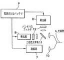
次に、図1を参照して、本発明の特定の実施形態について説明する。光システム2は、これらに限定されないが電磁エネルギーエミッタ、電磁エネルギー検出器、各種のミラー、フィルタ、電子機器、ホログラフィック光学系、二色性素子、および、調査放射(interrogating radiation)を電磁エネルギーエミッタから光導管を下って検出素子に送信したあと、戻り発光信号を解析し解釈するために必要な光学基準(optical standard)を含む素子の組み合わせを備える。リポータ基からの戻り発光信号は、検出されるアナライトの濃度の変化に応答して変化する。光システム2は、信号処理、1または2以上の信号の数学的操作、ならびにデータの格納および取り扱いを処理するコンピュータまたはマイクロプロセッサ3を装備することもできる。コンピュータまたはマイクロプロセッサ3は、光システムの他のコンポーネントと物理的に接触させることができるが、好ましい実施形態では、光システムの他のコンポーネントから最大で数メートルまで物理的に分離させることもできる。この実施形態では、光システム内の電磁エネルギー検出器および電子処理素子からの情報はワイヤレス(無線)でコンピュータまたはマイクロプロセッサ3に伝達される。コンピュータまたはマイクロプロセッサ3は、検出素子に固有の較正情報を格納することもできる。光システム2で発生した1または2以上の波長の光は、光導管4を下って検出素子6に伝達される。光導管4は光ファイバにすることも、光を最小損失で伝達する短光導波路(short lightguide)にすることもできる。検出素子6は、1または2以上の結合蛋白質からなり、1または2以上の関連発光性リポータ基が、ポリマーマトリックスに固定されているか、ポリマー連鎖に取り付けられているか、使い捨て先端に組み込まれているか、光導管の遠位端に直接的に取り付けられているか、あるいはコネクタに取り付けられている。検出素子6は、任意選択として、参照または較正信号を得る目的で、生体分子、ポリマーまたは有機分子に取り付けられた追加の発光性参照基を含むこともできる。検出素子6は、光導管4の遠位端に直接にまたはポリマーマトリックスを介して取り付けることができるが、好ましい実施形態では、光導管4の遠位端に取り付けられた使い捨て先端5に取り付けられる。このケースでは、使い捨て先端5は、接着剤を介して機械的に、または当業者に知られている任意の他の適当な手段によって、光導管4に対して配置されている。A specific embodiment of the present invention will now be described with reference to FIG. The
図2は、2つの代表的実施形態における光システム2を示す拡大図である。図2Aにおいて、ダイクロイックミラーまたはビームスプリッタ11を使用して、光が電磁エネルギーソース7から光導管4に向けられる。励起ソースは、例えば、アークランプ、レーザダイオードまたはLEDで構成できるが、これらに限定されない。この実施形態では、光導管4は光ファイバケーブルであり、励起光を電磁エネルギーソース7から検出素子6に伝達するためにも、リポータ基または参照基からの発光信号を光システム2に戻すように伝達するためにも、同じケーブルが使用されている。ダイクロイック素子11は、好ましくは、戻り信号を励起光から分離し、信号を電磁エネルギー検出器8に向ける。検出器は、例えば、フォトダイオード、CCDチップまたは光電子倍増管を含むことができるが、これらに限定されない。複数の発光信号が検出素子から戻される場合には、戻り信号の一部を複数の検出器に向けるために追加のダイクロイック素子を使用することができる。好ましくは、アナライトに反応しない発光性参照基をアナライト依存性リポータ分子と一緒に含めておくと、参照信号が得られる。この参照信号は、例えば、光または電子ドリフトを補正するために使用することができる。FIG. 2 is an enlarged view showing the
図2Bは、検出素子との間で光を送受伝達するために2分岐光ファイバ束(bifurcated optical bundle)または溶融型光ファイバ構成(fused optical fiber arrangement)が使用されている第2の実施形態を示す図である。ここでは、励起ソース7からの光は、2分岐光ファイバ束の一方のアームを下って伝達される。検出素子からの戻り発光信号は2分岐光ファイバの他方のアームを使用して検出されるので、このケースでは、光ファイバ束は励起を戻り発光から分離する働きをする。ダイクロイック光学系、ビームスプリッタまたは偏光器(polarizer)を付加的に使用して、例えば波長または偏光に基づいて戻り発光をさらに分割することができる。任意選択として、検出される発光波長を選択するためにバンドパスフィルタ12を使用することができる。電源9は光システム2に電力を供給する。 FIG. 2B illustrates a second embodiment in which a bifurcated optical bundle or a fused optical fiber arrangement is used to transmit and receive light to and from the sensing element. FIG. Here, the light from the
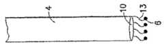
図3は、例えば、光導管が光ファイバで構成されているとき、検出素子6を光導管4の端部に取り付ける種々の代表的方法または手段を示している。当業者ならば理解されるように、図3に図示の代表的取り付け方法のいずれにおいても、検出素子6と光ファイバ4との間を十分に接触または密接させたり、動作時に検出素子6が光ファイバから剥離するのを防止して、光が効率的に検出素子6との間で送受されることを保証するといった設計上の考慮事項に注意が払われるべきである。さらに、動作時間中に検出素子の保全性を維持することは、信頼の高い信号応答が得られることを保証するために重要である。例えば、生体内で使用されるとき、検出素子6は、収縮、膨張、劣化の原因となったり、信号強度、発光、応答時間などを含む他の望ましい機能特性にマイナスの影響を及ぼしたりする種々の環境の影響を受けるおそれがある。従って、最適な取り付け方法または手段は、特定の検出素子または特定の応用分野の特性、構成、および寸法に応じて変化することがある。図3に図示の実施形態のすべては、一般的に光ファイバ4の遠位端10を光ファイバ4の軸に直角の平面として示しているが、代替実施形態では、遠位端10を複合/合成/湾曲した面にすることも、テーパ状または軸に対して角度を付けることもできる。図3に図示の取り付け方法は好ましい実施形態であり、個別でも組み合わせでも使用することができる。 FIG. 3 shows various exemplary methods or means for attaching the
ある特定の実施形態では、検出素子6は、例えば、共有結合性、イオン性またはファンデルワールス相互作用、ディップコーティング、スピンコーティング、プラズマコーティング、真空蒸着、インクジェット技術またはこれらの組み合わせを使用して、光ファイバ4の遠位端10に直接取り付けることができる。図3Aを参照すると、結合蛋白質、関連リポータ基および任意選択の参照基を備える検出素子は代替的に、例えば単層または長鎖ポリマーなどのポリマ13に取り付けることができ、ポリマー13は、例えばディップまたはスピンコーティング、プラズマコーティング、真空蒸着、共有結合性、イオン性またはファンデルワールス相互作用、インクジェット技術、またはこれらの組み合わせを使用して光ファイバ14の遠位端10に直接取り付けることができる。In certain embodiments, the
図3Bに示す別の実施形態では、検出素子6はポリマーマトリックス14に固定することができ、ポリマーマトリックス14は、例えば、接着剤、ディップまたはスピンコーティング、プラズマコーティング、射出成形、インクジェット技術、共有結合性、イオン性またはファンデルワールス相互作用、機械的コネクタあるいはこれらの組み合わせを使用して光ファイバ4の遠位端10に取り付け可能になっている。好ましい実施形態では、ポリマーマトリックス14と蛋白質の反応基が、例えば、アミン基をガラスまたはシリカファイバの遠位端の先端または表面10に導入することによって、検出素子6を光ファイバ4に直接共有結合するために使用されている。マトリックス14は、好ましくは、信号伝達または信号の大きさと応答時間との関係を最適化する構成および寸法になっている。この点に関して、好ましい実施形態では、マトリックス14が光ファイバ4の遠位端の表面10から突出する高さまたは距離15は、約5ミクロンまたはそれ以下から約1mmまでの間になっている。例えば、ある動作例では、応答時間はマトリックス高さ15が約50ミクロンであるとき約3秒であった。一般的に、マトリックスの高さ15が小さくなると、応答時間の短縮化が達成されるが、信号応答時間は、例えば、正確な寸法、水和状態または特定の用途などの、他の条件に応じて変化することがある。ある代替実施形態では、光反射面が光ファイバ4に面している反射または光散乱材料層をマトリックス14の最遠位端表面16に設けて、発光を向上し、および/または戻り信号を増幅することを可能にしている。ある変形実施形態では、反射材料層に、プラズマまたはスパッタコーティングまたはマトリックス14に取り付けられた薄膜光散乱面を設けることができる。さらに別の実施形態では、光反射粒子状物質をマトリックス全体に分散させて、光散乱効果を向上することを可能にしている。 In another embodiment shown in FIG. 3B, the
図3Cに示す別の実施形態では、プラスチックまたはポリマースリーブ17を光ファイバ4の遠位端上に設けて、検出素子(図示せず)を格納および/または保護することができる。検出素子は図3Bに示すように、ポリマーマトリックス内に閉じ込めるか、あるいはポリマーマトリックスに接続することができる。このポリマーマトリックスは、検出素子を収容している場合と収容していない場合があるが、射出、注入(pouring)またはディッピングによってスリーブ内に挿入することができ、そのあと、スリーブ17内で架橋結合(cross−link)させるか、重合化させることができる。ポリマーマトリックスが検出素子なしでスリーブ内に導入される場合は、検出素子は続いてポリマーマトリックス内に導入または分散され、検出素子をマトリックスに閉じ込めるか、結合するか、あるいは共有結合的に取り付けることができる。別の方法として、検出素子6は、光ファイバ4の挿入の前にスリーブ17内で重合化させることができる。動作時には、検出素子6と光ファイバ4を備えるスリーブ17は、継続的または一時的使用のために生体内に埋め込むことができる。検出素子6がスリーブ17内に位置している代替実施形態では、スリーブ17は取り外し可能に光ファイバ4に結合可能にし、光ファイバ4はスリーブ17から出し入れするように取り外し可能に挿入可能にして、スリーブ17の一部または全体を生体内に残したままにし、光ファイバ4を一時的使用のために必要に応じて挿入し、取り外しできるようにすることができる。代替実施形態では、スリーブ17の代わりに異種のハウジングを使用することができる。 In another embodiment shown in FIG. 3C, a plastic or
図3Dに示す別の実施形態では、光ファイバ4がニードル(needle)18の内側内に保持されている。ここで使用されている「ニードル」という用語には、マイクロニードルが含まれるが、これに限定されない。ニードル18は、貫通深さ(piercing depth)を制御するためのベベル20のような変形された遠位端19及び/又はアナライトがニードル18に収められた検出素子6に接近することを可能にする1または2以上のサイドポートを有することができる。検出素子6は、図3A、図3Bまたは図3Cの説明の中で記述されている方法のいずれかを使用して光ファイバ4に直接接続されるように、ニードル18の内側に位置している。これとは別に、検出素子6は光ファイバ4と機械的に接触させるだけにすることも可能である。代替実施形態では、ニードル18の遠位端は、検出素子6をニードル18に機械的に固定するために圧着する(crimp)ことができる。好ましい実施形態では、光ファイバ4の外径23は約50−400ミクロンの範囲にあり、好ましくは約50−200ミクロンの範囲にあり、ニードル18の内径27は光ファイバ4をニードル18内に挿入することを可能にするために外径23よりも若干大きな寸法になっている。ある変形実施形態では、ニードル18は、例えば、摩擦ばめ(friction fit)またはニードル18を光ファイバ上に圧着することによって、光ファイバ4に機械的に固定することができる。代替実施形態では、光ファイバ4は、接着剤または当業者に既知の他の適当な手段によって化学的にニードル18内に固定することができる。この点に関して、集積された光ファイバと検出素子を有するニードルを備えるバイオセンサ先端アセンブリは、一時的使用の場合は使い捨てとして製造し、継続的使用の場合は生体内に残しておくことができる。別の実施形態では、光ファイバ4は取り外し可能にニードル18から出し入れできるようにして、ニードル18は生体内に残し、光ファイバ4は一時的使用のため必要に応じて挿入と取り外しができるようにしている。ある好ましい実施形態では、ニードル18の近位端は、取り付け可能な光コンポーネントを受け入れる構成および寸法になった光結合部を備え、例えば、図2Aまたは2Bに示すような光システムに接続され、あるいは光システムとのインタフェースとなっている。好ましい実施形態では、ニードル18は直線ニードルになっているが、代替実施形態では、ニードル18はその長さ方向の任意の個所に1または2以上のベンド(bend)または屈曲部を備えることが可能になっている。さらに、図3Eに図示の別の代替実施形態では、ニードル18の遠位端は、マトリックス14から遠位端方向に突出し、かつマトリックス14に隣接している屈曲先端部29を遠位端に備えると共に、反射または光拡散面または層30を備え、光反射面は光ファイバ4に面して、発光を向上しかつ/または戻り信号を増幅することを可能にしている。図3Fに示すニードルアセンブリの別の実施形態では、ニードル18の遠位端19は、そこからアナライトが流れ、または移動する1または2以上のポートまたは穴31を備え、アナライトがニードル18に収められた検出素子6に接近することを可能にしている。 In another embodiment shown in FIG. 3D, the
図4は、着用可能光バイオセンサの例示的実施形態を示す図である。この実施形態では、先端本体(tip body)21は、長さがほぼ1〜10mmのスチールニードルを備え、光ファイバ22上に固定された検出素子6がそこに収められている。光ファイバ4、検出素子6およびニードル21は、マウント24内に位置している。光ファイバ4と検出素子6を収めている先端本体またはニードル21は患者の皮膚内に垂直に挿入され、検出素子6が皮内と皮下のいずれかに置かれる。例示的実施形態では、ニードル21はマウント24上に固定装着され、制御された挿入深さが得られるようにしている。この点に関して、ニードル21は、好ましくは、約0.1mmから約10mmまでの距離、最も好ましくは、約1mmから約2mmまでの距離だけ患者の皮膚内に入り込む。そのあと、接着リング25がマウントとニードルのアセンブリを定位置に保持する。次に、光システムはマウントとニードルのアセンブリ上をクランプし、コネクタ26は光ファイバ22と光システム2とのインタフェースとなっている。光リーダは、例えば、約0.02〜1メートルだけプラットフォームから分離され、光ファイバでシステムの他の部分に接続可能になっている。光システムは、例えば、図2Aまたは図2Bに示すどちらかの光実施形態に従って設計することができる。励振源は、例えば、アークランプ、レーザダイオードまたはLEDで構成できるが、これらに限定されない。検出器は、フォトダイオード、CCDチップ、または光電子倍増管で構成できるが、これらに限定されない。代替実施形態では、複数の先端本体またはニードルアセンブリ21が単一のマウント24に取り付け可能になっている。この点に関して、先端本体またはニードルアセンブリは複数のアナライトを検査(test)し、各ニードルアセンブリは1つのアナライトを検査する構成にすることができる。別の実施形態では、先端本体またはニードルアセンブリは、薬剤が少なくとも1つの先端本体またはニードルアセンブリから投与できるようにマウント24に取り付け可能になっている。従って、ドラッグデリバリーシステムは、正しい投薬量がアナライトのテストに基づいて計算され、同一のバイオセンサマウント24に取り付けられた先端本体またはニードルアセンブリから投与されるように設計することができる。この実施形態で、投薬のために使用される先端本体またはニードルアセンブリは、そこから薬剤を投与するための1または2以上のポートを備えることができる。さらに別の実施形態では、温度プローブを、少なくとも1つの先端本体またはニードルアセンブリ内に収容させることも、そこに隣接させることも、あるいはそこに取り付けることも可能になっている。この温度プローブの例としては、熱電対、または、例えば温度感受性フルオロフォアを使用した光学温度モニタがある。別の変形形態では、バイオセンサ先端は着用可能パッチデバイスに組み込むことが可能であり、そこでは先端本体の近位端がパッチに取り付けられ、パッチは患者の外側の皮膚(exterior skin)に着用される構造と寸法になっている。別の実施形態では、バイオセンサ先端は時計に組み込むことが可能であり、そこでは先端本体の近位端が時計に取り付けられ、時計は患者の外側手首部分に着用される構造および寸法になっている。 FIG. 4 illustrates an exemplary embodiment of a wearable optical biosensor. In this embodiment, the
上述した実施形態のすべてにおいて、アセンブルされた光ファイバおよび検出素子、または製造された先端デバイスは無菌になっている。この点に関して、「無菌(sterile)」とは、微生物またはバクテリアが本質的に存在しないことを意味する。ある製造方法では、アセンブルされたコンポーネントは製造ステップごとに定期的に殺菌処理されている。例えば、図3Cに示す実施形態では、スリーブは製造ステップごとに殺菌処理され、最終的に無菌にパッケージされたデバイスが得られている。別の方法として、アセンブルされた光ファイバおよび検出素子または製造された先端デバイスは最終ステップで殺菌処理することができる。 In all of the embodiments described above, the assembled optical fiber and sensing element, or manufactured tip device, is sterile. In this regard, “sterile” means essentially free of microorganisms or bacteria. In some manufacturing methods, the assembled components are periodically sterilized at each manufacturing step. For example, in the embodiment shown in FIG. 3C, the sleeve is sterilized at each manufacturing step, resulting in a device that is packaged aseptically. Alternatively, the assembled optical fiber and sensing element or manufactured tip device can be sterilized in the final step.
以下の例は、本発明のいくつかの好ましい実施形態を示したもので、単に例示的実施形態を示すことを目的としている。ここでは、非特許文献8または他の文献に記載されている手順に従って、フルオロフォアリポータプローブを有する標識突然変異結合蛋白質(labeled mutated binding protein)が使用されている。 The following examples illustrate some preferred embodiments of the present invention and are merely intended to illustrate exemplary embodiments. Here, a labeled mutant binding protein having a fluorophore reporter probe is used according to the procedure described in
例1
本発明の一実施形態によれば、グルコース・ガラクトース結合蛋白質(GGBP)は、グルタミン酸を位置149で置換したシステインと、アラミンを位置213で置換したアルギニンと、ロイシンを位置238で置換したセリンとを含むトリプル突然変異(triple mutation)(E149C/A213R/L238S)と共に使用された。この蛋白質は位置149で、N,N’−ジメチル−N−(ヨードアセチル)−N’−(7−ニトロベンジン−2−オキサ−1,3−ジアゾール)−4−イル)エチレンジアミン(IANBDアミド)オキシ(N,N’−dimethyl−N−(iodoacetyl)−N’−(7−nitrobenz−2−oxa−1,3−diazol−4−yl)ethylenediamine(IANBD amide)oxy)で標識付けられた。この突然変異GGBP(E149C/A213R/L238S)はグルコースに固有であり、リポータ基はグルコース結合に応答して蛍光強度変化を生じる。
Example 1
According to one embodiment of the present invention, glucose galactose binding protein (GGBP) comprises cysteine substituted with glutamic acid at position 149, arginine substituted with alamin at position 213, and serine substituted with leucine at position 238. Used with triple mutation (E149C / A213R / L238S). This protein is at position 149, N, N'-dimethyl-N- (iodoacetyl) -N '-(7-nitrobenz-2-oxa-1,3-diazol) -4-yl) ethylenediamine (IANBD amide) It was labeled with oxy (N, N′-dimethyl-N- (iodoacetyl) -N ′-(7-nitrobenzo-2-oxa-1,3-diazol-4-yl) ethylenediamine (IANBD amide) oxy). This mutant GGBP (E149C / A213R / L238S) is unique to glucose and the reportergroup produces a change in fluorescence intensity in response to glucose binding.
マルチコーティングまたはマルチレイヤのマトリックスは次のように作製された。コアマトリックスは、発光性または染料標識付結合蛋白質(特許文献9に記載されているように作製されたPBSバッファにおける15μM,pH7.4)1に対して2から4の3重量%アルギン酸塩(v/v)をシンチレーションバイアル内で混合し、低速でボルテックスして形成された。結果として得られた蛋白質−アルギン酸塩混合液3mLをシリンジに入れ、ミキサで10mL/hrのレートで200mlの1M CaCl2に注入することにより、0.4〜1.5mm径のビーズ(bead)を形成した。これらのビーズは、CaCl2溶液中にミキサで15〜60分間混合された。次に、ポリ−L−リシン0.01%w/v水溶液約10mL中に上方からビーズを1時間入れることによって閉じ込め層(containment layer)が形成され、そのあと、ポリリシンコーティングビーズを15〜30分間吸収タオル上で乾燥した。この時点で、センサは使用の準備が整った。A multi-coating or multi-layer matrix was made as follows. The core matrix is a luminescent or dye-labeled binding protein (15 μM in a PBS buffer made as described in US Pat. / V) was mixed in a scintillation vial and vortexed at low speed. The resulting protein-
この実施形態で使用されたファイバは二分岐光ファイバであった。この光ファイバは、中心の400μmファイバの周囲に6本の400μmファイバが配置されている。6本のファイバは励起導管として使用され、中心のファイバは検出導管として使用された。ファイバの総直径は1.4 mmであった。ファイバが研磨されたあと、検出素子を光ファイバの遠位端に粘着するためにLoctite 401メディカルグレード接着剤が使用された。ファイバの近位端は二分岐され、一方のアームは励振源に通じ、他方のアームは検出器に通じていた。470nmLEDが励振源として使用され、商用蛍光スペクトロメータが電磁エネルギー検出器として使用された。540nmでの放出強度が測定された。 The fiber used in this embodiment was a bifurcated optical fiber. In this optical fiber, six 400 μm fibers are arranged around a central 400 μm fiber. Six fibers were used as the excitation conduit and the center fiber was used as the detection conduit. The total fiber diameter was 1.4 mm. After the fiber was polished, Loctite 401 medical grade adhesive was used to adhere the sensing element to the distal end of the optical fiber. The proximal end of the fiber was bifurcated, with one arm leading to the excitation source and the other arm leading to the detector. A 470 nm LED was used as the excitation source and a commercial fluorescence spectrometer was used as the electromagnetic energy detector. The emission intensity at 540 nm was measured.
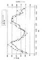
試験において、上記のように形成されたバイオセンサの遠位端と検出素子が、13ゲージニードルを通して麻酔状態の豚の皮下1〜2mmの脇腹に挿入された。10%のデキストロースを含む乳酸加リンガー溶液と含まない乳酸加リンガー溶液を交互に豚の耳静脈に注入して、豚のグルコースレベルを制御下で増減した。間隔を置いて、食道カテーテルを通して豚の大静脈から血液サンプルが採血され、血糖値がハンドヘルド血液グルコースメータでテストされた。図5に示すように、麻酔状態の豚のグルコースレベルの変化を追跡するためにバイオセンサの蛍光強度が観察された。 In the test, the biosensor distal end and sensing element formed as described above were inserted through a 13-gauge needle into the subcutaneous 1-2 mm flank of an anesthetized pig. Lactated Ringer's solution containing 10% dextrose and lactated Ringer's solution not containing dextrose were alternately injected into the ear vein of the pig, and the glucose level of the pig was increased or decreased under control. At intervals, blood samples were drawn from the porcine vena cava through the esophageal catheter and blood glucose levels were tested with a handheld blood glucose meter. As shown in FIG. 5, the fluorescence intensity of the biosensor was observed to track changes in glucose levels in anesthetized pigs.
例2
別の実施形態では、結合蛋白質は、グルタミン酸を位置149で置換したシステインと、アラニンを位置213で置換したアルギニンと、ロイシンを位置238で置換したセリンとを有するグルコース−ガラクトース結合蛋白質(GGBP)であった(E149C/A213R/L238S)。この蛋白質は位置149でN,N’−ジメチル−N−(ヨードアセチル)−N’−(7−ニトロベンジン−2−オキサ−,3−ジアゾール−4−イル)エチレンジアミン(IANBDアミド)(N,N’−dimethyl−N−(iodoacetyl)−N’−(7−nitrobenz−2−oxa−,3−diazol−4−yl)ethylenediamine(IANBD amide))で標識付けられた。バイオセンサは、400ミクロンコア径ファイバの先端をカテーテルチューブの短片内に挿入し、カテーテルチューブを0.1〜1mmだけファイバ先端上に突出させることによって作製された。ファイバはシリカコア、シリカクラッディング、およびポリアミドバッファを備えていた。ファイバ径は400/440/470ミクロンであったが、ここでスラッシュは、コア、クラッディング、バッファの外側から測定した径を示している。Example 2
In another embodiment, the binding protein is a glucose-galactose binding protein (GGBP) having a cysteine substituted with glutamic acid at position 149, an arginine substituted with alanine at position 213, and a serine substituted with leucine at position 238. (E149C / A213R / L238S). This protein is N, N′-dimethyl-N- (iodoacetyl) -N ′-(7-nitrobenz-2-oxa-, 3-diazol-4-yl) ethylenediamine (IANBD amide) (N, N) at position 149. N'-dimethyl-N- (iodoacetyl) -N '-(7-nitrobenz-2-oxa-, 3-diazol-4-yl) ethylenediamine (IANBD amide)). The biosensor was made by inserting the tip of a 400 micron core diameter fiber into a short piece of catheter tube and projecting the catheter tube by 0.1-1 mm over the fiber tip. The fiber had a silica core, a silica cladding, and a polyamide buffer. The fiber diameter was 400/440/470 microns, where the slash indicates the diameter measured from the outside of the core, cladding, and buffer.
固定化マトリックスは、架橋結合されたアルギン酸塩ベースのハイドロゲル(alginate−based hydrogel)であり、これはPronova(商標)UP LVGアルギン酸塩を、カーボキシルを通してカルボジイミド化学作用によってアジピン酸ジヒドラジドと共有結合的に架橋結合することによって作製された。Pronova(商標)がこの実施形態で選択されたのは、その粘性が低く、またグルロニック対マヌロニック(guluronic to mannuronic)比が高いためである。アルギン酸塩1グラムを50mL 0.1M MESバッファ(pH 6.5)内で溶解したあと、AAD 110mgおよびヒドロキシベンゾトリアゾール(HOBt)79mgを添加することによって2%アルギン酸塩溶液が作製された。この溶液は使用されるまで4℃で保管された。アルギン酸塩溶液に、溶液10mL当たり145mgの1−エチル−3−(3−ジメチルアミノ−プロピル)カルボジイミド(EDC)が、デュアルシリンジ混合法(dual−syringe mixing technique)を用いて添加された。アルギン酸塩、AAD、HOBt、EDC混合液は1mLシリンジに吸入され、先端の尖っていない30ゲージニードルがシリンジに取り付けられた。ニードルが準備状態に置かれたあと、先端が光ファイバ上のカテーテルチュービングモールドに挿入された。ファイバ上のカテーテルチュービングは充満され、光ファイバの先端とアルギン酸塩マトリックスとの間に良好な接触が確保された。マトリックスは15分間架橋結合するように放置され、そのあとファイバ先端とマトリックスアセンブリは0.1M、6.5pH MES溶液に移され、そこで、これらは2時間保管された。2時間経過後、検出先端は余剰燐酸塩バッファ溶液(PBS、0.0027M 塩化カリウム、0.137塩化ナトリウム、pH7.4)の中に置かれ、そこで、これらは反応を抑えるために少なくとも30分間保管された。 The immobilization matrix is a cross-linked alginate-based hydrogel, which covalently bonds Pronova ™ UP LVG alginate with adipic acid dihydrazide through carbodiimide chemistry through carboxyl. It was made by cross-linking. Pronova (TM) was selected in this embodiment because of its low viscosity and high guluronic to manuronic ratio. After dissolving 1 gram of alginate in 50 mL 0.1 M MES buffer (pH 6.5), a 2% alginate solution was made by adding 110 mg AAD and 79 mg hydroxybenzotriazole (HOBt). This solution was stored at 4 ° C. until used. To the alginate solution, 145 mg of 1-ethyl-3- (3-dimethylamino-propyl) carbodiimide (EDC) per 10 mL of the solution was added using a dual-syringe mixing technique. The mixture of alginate, AAD, HOBt, and EDC was sucked into a 1 mL syringe, and a 30-gauge needle with a sharp tip was attached to the syringe. After the needle was ready, the tip was inserted into a catheter tubing mold on the optical fiber. The catheter tubing on the fiber was full and good contact was ensured between the tip of the optical fiber and the alginate matrix. The matrix was left to crosslink for 15 minutes, after which the fiber tip and matrix assembly were transferred to a 0.1 M, 6.5 pH MES solution where they were stored for 2 hours. After 2 hours, the detection tips are placed in excess phosphate buffer solution (PBS, 0.0027M potassium chloride, 0.137 sodium chloride, pH 7.4), where they are at least 30 minutes to suppress the reaction. Saved.
結合蛋白質を取り付けるために、先端は約8時間、標識付きGGBPのPBSバッファ 中での溶液[NBD−E149C/A213R/L238S GGBP](53μM、50μL)の中で培養された。センサはこの培養期間周囲光から保護された。8〜24時間の培養後、50μLのEDC/NHS(200mM/50/0mM)が培養管に添加された。40分後、センサ先端は取り出され、反応を抑えるために1M、pH8.5エタノールアミン50μLに入れられた。エタノールアミン溶液に入れられた20分後、センサ先端はPBS溶液に移され、そこで、これらは少なくとも24時間、未反応の蛋白質が放散する間放置された。そのあと、センサは未使用のPBSに移され、使用準備状態になるまで暗室に保管された。 To attach the binding protein, the tip was cultured in a solution of labeled GGBP in PBS [NBD-E149C / A213R / L238S GGBP] (53 μM, 50 μL) for about 8 hours. The sensor was protected from ambient light during this incubation period. After 8-24 hours of culture, 50 μL of EDC / NHS (200 mM / 50/0 mM) was added to the culture tube. After 40 minutes, the sensor tip was removed and placed in 50 μL of 1M, pH 8.5 ethanolamine to suppress the reaction. Twenty minutes after being placed in the ethanolamine solution, the sensor tips were transferred to a PBS solution where they were left for at least 24 hours while the unreacted protein was released. The sensor was then transferred to unused PBS and stored in a dark room until ready for use.
この例におけるファイバはシングル400μmコアマルチモードファイバ(シリカコア、シリカクラッディング、ポリアミドバッファ)であった。この実施例では、同じファイバが励起信号と発光信号の両方を伝達しているので、図2Aに示すように、発光を励起から分離するために二色性光学系が使用された。励起は470nmLEDで行なわれた。470nm励起をファイバの入力端側に反射し、中心が550nmである蛍光を検出器に伝達するために商用二色性フィルタが使用された。ガラス非球面レンズは、ビームコリメーションと光をファイバ内と検出器上に集束させるために使用された。散乱された励起は、さらに550nmバンドパスフィルタを使用して検出器から除去された。SMAコネクタは、光ファイバセンサとの接続と切り離しを迅速化した。この実施形態の電磁エネルギー検出器は、単一光子計数光電子倍増管であった。データ収集は、RS−232コネクタを通して検出器と通信するラップトップコンピュータで行なわれた。 The fiber in this example was a single 400 μm core multimode fiber (silica core, silica cladding, polyamide buffer). In this example, a dichroic optical system was used to separate the emission from the excitation, as shown in FIG. 2A, because the same fiber carries both the excitation and emission signals. Excitation was performed with a 470 nm LED. A commercial dichroic filter was used to reflect the 470 nm excitation to the input end of the fiber and transmit the fluorescence centered at 550 nm to the detector. Glass aspheric lenses were used to focus beam collimation and light into the fiber and onto the detector. Scattered excitation was further removed from the detector using a 550 nm bandpass filter. The SMA connector speeds up the connection and disconnection with the optical fiber sensor. The electromagnetic energy detector of this embodiment was a single photon counting photomultiplier tube. Data collection was performed on a laptop computer communicating with the detector through an RS-232 connector.
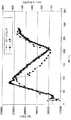
図6:試験において、上記のように形成されたバイオセンサの遠位端と検出素子は、グルコース濃度が異なっている豚血清(porcine serum)溶液に挿入された。すべての豚血清溶液は200ミクロンフィルタに通してフィルタ処理され、溶液中のグルコースレベルが臨床分析機器で測定された。図6はセンサの生体外性能を示す図である。血清中の初期グルコースレベルは56mg/dLと測定された。150および300mg/dLの血清サンプルがPBS内の濃度1Mのグルコースを血清のアリコートに打ち込むことによって作製された。 FIG. 6: In the test, the distal end of the biosensor formed as described above and the sensing element were inserted into porcine serum solution with different glucose concentrations. All porcine serum solutions were filtered through a 200 micron filter and the glucose level in the solution was measured with a clinical analyzer. FIG. 6 shows the in vitro performance of the sensor. The initial glucose level in serum was measured as 56 mg / dL. 150 and 300 mg / dL serum samples were made by driving a concentration of 1M glucose in PBS into an aliquot of serum.
例3
本発明の別の実施形態では、バイオセンサは薄膜を光ファイバの表面に共有結合で取り付けることによって形成された。結合蛋白質は、グルタミン酸を位置149で置換したシステインと、アラニンを位置213で置換したアルギニンと、ロイシンを位置238で置換したセリンとを有するグルコース−ガラクトース結合蛋白質(GGBP)であった(E149C/A213R/L238S)。蛋白質は位置149でN,N’−ジメチル−N−(ヨードアセチル)−N’−(7−ニトロベンジン−2−オキサ−1,3−ジアゾール−3−イル)エチレンジアミン(IANBDアミド)(N,N’−dimethyl−N−(iodoacetyl)−N’−(7−nitrobenz−2−oxa−1,3−diazol−3−yl)ethylenediamine(IANBD amide))で標識付けられた。Example 3
In another embodiment of the present invention, the biosensor was formed by covalently attaching a thin film to the surface of an optical fiber. The binding protein was a glucose-galactose binding protein (GGBP) having cysteine substituted with glutamic acid at position 149, arginine substituted with alanine at position 213, and serine substituted with leucine at position 238 (E149C / A213R). / L238S). The protein is N, N′-dimethyl-N- (iodoacetyl) -N ′-(7-nitrobenz-2-oxa-1,3-diazol-3-yl) ethylenediamine (IANBD amide) (N, at position 149) N'-dimethyl-N- (iodoacetyl) -N '-(7-nitrobenz-2-oxa-1,3-diazol-3-yl) ethylenediamine (IANBD amide)).
バイオセンサは、アルギン酸塩マトリックスをシリカファイバのアミン官能性(amine−functionalized)表面に共有結合で接続することによって作製された。ファイバはシリカコア、シリカクラッディング、およびポリアミドバッファを備えていた。ファイバ径は400/440/470ミクロンであり、ここでスラッシュはコア/クラッディング/バッファの外側から測定された径を示している。 The biosensor was made by covalently connecting the alginate matrix to the amine-functionalized surface of the silica fiber. The fiber had a silica core, a silica cladding, and a polyamide buffer. The fiber diameter is 400/440/470 microns, where the slash indicates the diameter measured from the outside of the core / cladding / buffer.
ポリアミドバッファは、ファイバの最後の数ミリメータを約1〜2秒間トーチ(torch)にさらすことによって光ファイバの先端から除かれた。ついで、残留ポリアミドが払拭された。次に、バッファが除かれた先端は1時間1M硫酸中に置かれた。そのあと、先端は蒸留水で洗浄され、15分間エタノール中に置かれたあと、15分間無水トルエン(anhydrous toluene)中に沈められた。洗浄された先端は、3−aminopropyltriethoxysilane(APTES)1%を含有する温かい(60℃)無水トルエン中に置かれ、5分間反応させたままにした。次に、先端はAPTES溶液から取り出され、15分間エタノールで洗浄された。このプロセスの終了時に、ファイバの表面上にアミン基が存在することが光電子分光法によって確認された。The polyamide buffer was removed from the tip of the optical fiber by exposing the last few millimeters of the fiber to a torch for about 1-2 seconds. The residual polyamide was then wiped away. The buffered tip was then placed in 1M sulfuric acid for 1 hour. The tip was then washed with distilled water, placed in ethanol for 15 minutes, and then submerged in anhydrous toluene for 15 minutes. The washed tips were placed in warm (60 ° C.) anhydrous toluene containing 1% 3-aminopropyltrioxysilane (APTES) and allowed to react for 5 minutes. The tip was then removed from the APTES solution and washed with ethanol for 15 minutes. At the end of this process, the presence of aminegroups on the fiber surface was confirmed by photoelectron spectroscopy.
ついで、アルギン酸塩マトリックスは、次のようにアミン官能性ファイバ表面に塗布された。固定化マトリックスは、架橋結合されたアルギン酸塩ベースのハイドロゲルであり、これは、その低粘度と高グルロニック対マヌロニック比のために選択されたPronova(商標)UP LVGアルギン酸塩を、カーボキシルを通してカルボジイミド化学作用によってアジピン酸ジヒドラジド(AAD)と共有結合で架橋結合することによって作製された。2%アルギン酸塩溶液は、50mL 0.1M MESバッファ(pH 6.5)中に1グラムのアルギン酸塩を溶解し、そのあとAAD110mgとヒドロキシベンゾトリアゾル(HOBt)79mgを添加することにより作製された。この溶液の0.5mLアリコートはついで、デュアルシリンジ混合法を用いてMESバッファ50μL中でEDC1mgと混合された。この溶液の総体積は約0.55mLであった。アルギン酸塩、AAD、HOBt、EDC混合液はついで、微小遠心バイアルに移され、APTES官能性ファイバ先端は3−4分間またはマトリックスが硬化を始めるまでアルギン酸塩溶液に沈められていた。そのあと、先端はアルギン酸塩溶液から取り出され、約1〜10分間空気中で反応を続けるように放置され、そのあと0.1M、6.5pH MESバッファに移された。先端は2時間MESバッファ中に置かれたあと、余剰燐酸塩バッファ(PBS、0.0027M塩化カリウム、0.137塩化ナトリウム、pH7.7)中で最低30分間クエンチされた。 The alginate matrix was then applied to the amine functional fiber surface as follows. The immobilization matrix is a cross-linked alginate-based hydrogel, which uses Pronova® UP LVG alginate, selected for its low viscosity and high gluuronic to manuronic ratio, through carbodiimide chemistry. It was made by covalently cross-linking with adipic acid dihydrazide (AAD) by action. A 2% alginate solution was made by dissolving 1 gram of alginate in 50 mL 0.1 M MES buffer (pH 6.5) followed by addition of 110 mg AAD and 79 mg hydroxybenzotriazol (HOBt). . A 0.5 mL aliquot of this solution was then mixed with 1 mg of EDC in 50 μL of MES buffer using the dual syringe mixing method. The total volume of this solution was about 0.55 mL. The alginate, AAD, HOBt, EDC mixture was then transferred to a microcentrifuge vial and the APTES functional fiber tip was submerged in the alginate solution for 3-4 minutes or until the matrix began to cure. The tip was then removed from the alginate solution and left to continue the reaction in air for about 1 to 10 minutes before being transferred to a 0.1 M, 6.5 pH MES buffer. The tip was placed in MES buffer for 2 hours and then quenched in excess phosphate buffer (PBS, 0.0027 M potassium chloride, 0.137 sodium chloride, pH 7.7) for a minimum of 30 minutes.
結合蛋白質を取り付けるために、先端はPBSバッファ[NBD−E149C/A213R/L238S GGBP](20〜60μM、50μL)において標識付きGGBP溶液中で7時間培養された。センサは培養期間中周囲光から保護された。約2〜8時間の培養後、50μLのEDC/NHS(200mM/50mM)が培養管に添加された。5〜40分後、センサ先端は取り出され、反応を抑える(quench)ために1M、pH8.5エタノールアミン50μL中に置かれた。エタノールアミン溶液中に20分間置かれたあと、センサ先端はPBS溶液に移され、そこで先端は少なくとも8時間、、未反応の蛋白質が放散する間放置された。センサは、そのあと新鮮なPBSに移され、使用準備状態に置かれるまで暗室に保管された。 In order to attach the binding protein, the tip was incubated in labeled GGBP solution in PBS buffer [NBD-E149C / A213R / L238S GGBP] (20-60 μM, 50 μL) for 7 hours. The sensor was protected from ambient light during the incubation period. After about 2-8 hours of culture, 50 μL of EDC / NHS (200 mM / 50 mM) was added to the culture tube. After 5-40 minutes, the sensor tip was removed and placed in 50 μL of 1M, pH 8.5 ethanolamine to quench the reaction. After being placed in the ethanolamine solution for 20 minutes, the sensor tip was transferred to a PBS solution where the tip was left for at least 8 hours while unreacted protein was released. The sensor was then transferred to fresh PBS and stored in a dark room until it was ready for use.
上述した実施形態の試験において、光リーダは、470nm励起がソレノイド駆動シャッタを使用して変調されたことを除き、前例で説明したものと同じであった。シャッタおよび検出器とのインタフェースとなって、これらを制御するほかに、蛍光測定値の定期的収集(timed acquisition)、結果のグラフィカル表示、データ分析および較正アルゴリズムはソフトウェアで行なわれた。 In the test of the embodiment described above, the optical reader was the same as described in the previous example, except that the 470 nm excitation was modulated using a solenoid driven shutter. Besides interfacing with and controlling the shutter and detector, timed acquisition of fluorescence measurements, graphical display of results, data analysis and calibration algorithms were performed in software.
以上のように形成されたバイオセンサの遠位端と検出素子は、次に、麻酔状態の豚の脇腹に挿入された。この挿入は、18〜24ゲージニードルで形成された皮膚の穴を通して皮内または皮下にファイバを挿入することで行なわれた。10%デクストロースを含む乳酸加リンガ溶液と含まない乳酸加リンガ溶液を交互に豚の耳静脈に注入して、豚のグルコースレベルを制御下で増減した。間隔を置いて、食道カテーテルを通して豚の大静脈から血液サンプルが採血され、血糖の測定値がハンドヘルド血液グルコースメータでテストされた。図7に示すように麻酔状態の豚の血液のグルコースレベルの変化を追跡するためにバイオセンサの蛍光強度が観察された。 The distal end and detection element of the biosensor formed as described above were then inserted into the flank of an anesthetized pig. This insertion was performed by inserting the fiber intradermally or subcutaneously through a skin hole formed with an 18-24 gauge needle. Lactated Ringer's solution containing 10% dextrose and lactated Ringer's solution containing no 10% dextrose were alternately injected into the ear vein of the pig, and the glucose level of the pig was increased or decreased under control. At intervals, blood samples were drawn from the porcine vena cava through the esophageal catheter, and blood glucose measurements were tested with a handheld blood glucose meter. As shown in FIG. 7, the fluorescence intensity of the biosensor was observed to track changes in glucose levels in blood of anesthetized pigs.
例4
本発明の別の実施形態では、内部光参照基によるデュアル波長検出が行なわれた。結合蛋白質は、グルタミン酸を位置149で置換したシステインと、アラニンを位置213で置換したアルギニンと、ロイシンを位置238で置換したセリンとを有するグルコース・ガラクトース結合蛋白質(GGBP)であった(E149C/A213R/L238S)。この蛋白質は位置149でN,N’−ジメチル−N−(ヨードアセチル)−N’−(7−ニトロベンジン−2−オキサ−1,3−ジアゾール−4−イル)エチレンジアミン(IANBDアミド)(N,N’−dimethyl−N−(iodoacetyl)−N’−(7−nitrobenz−2−oxa−1,3−diazol−4−yl)ethylenediamine(IANBD amide))で標識付けられた。参照基は、グルタミン酸が位置149でシステインに置換されたGGDP(TR−E149C GGBP)に取り付けられたTexas Red(登録商標)C2マレイミドであった。グルコース濃度の生理的範囲にわたって、TR−E149C GGBPからの発光は実質的に変化せず、したがってTR−E149C GGBPはアナライト依存結合蛋白質とリポータ基(NBD−E149C/A213R/L238S GGBP)からの信号の内部参照に役立っている。Example 4
In another embodiment of the present invention, dual wavelength detection with an internal light referencegroup was performed. The binding protein was a glucose-galactose binding protein (GGBP) having cysteine substituted with glutamic acid at position 149, arginine substituted with alanine at position 213, and serine substituted with leucine at position 238 (E149C / A213R). / L238S). This protein is N, N'-dimethyl-N- (iodoacetyl) -N '-(7-nitrobenz-2-oxa-1,3-diazol-4-yl) ethylenediamine (IANBD amide) (N , N′-dimethyl-N- (iodoacetyl) -N ′-(7-nitrobenzo-2-oxa-1,3-diazol-4-yl) ethylenediamine (IANBD amide)). The referencegroup was Texas Red® C2 maleimide attached to GGDP (TR-E149C GGBP) where glutamic acid was replaced with cysteine at position 149. Over the physiological range of glucose concentration, the luminescence from TR-E149C GGBP does not change substantially, so TR-E149C GGBP is a signal from the analyte-dependent binding protein and reportergroup (NBD-E149C / A213R / L238S GGBP). Useful for internal reference.
バイオセンサは、400ミクロンコア径ファイバの先端をカテーテルチューブの短片内に挿入し、カテーテルチューブを0.1〜0.5mmだけファイバ先端上に突出させることによって作製された。ファイバはシリカコア、シリカクラッディング、およびポリイミドバッファを備えていた。ファイバ径は400/440/470ミクロンであったが、ここでスラッシュはコア、クラッディング、バッファの外側から測定した径を示している。 The biosensor was made by inserting the tip of a 400 micron core diameter fiber into a short piece of catheter tube and projecting the catheter tube over the fiber tip by 0.1-0.5 mm. The fiber had a silica core, silica cladding, and a polyimide buffer. The fiber diameter was 400/440/470 microns, where the slash indicates the diameter measured from the outside of the core, cladding, and buffer.
固定化マトリックスは架橋結合されたアルギン酸塩ベースのハイドロゲルであり、これは、その粘性が低く、グルロニック対マヌロニック比が高いために選択されたPronova(商標)UP LVGアルギン酸塩を、カーボキシルを通してカルボジイミド化学作用によってアジピン酸ジヒドラジド(AAD)と共有結合的に架橋結合することによって作製された。2%アルギン酸塩溶液は、アルギン酸塩1グラムを50mL 0.1M MESバッファ(pH 6.5)内で溶解したあと、AAD110mgおよびヒドロキシベンゾトリアゾル(HOBt)79mgを添加することによって作製された。この溶液は使用されるまで4℃で保管された。デュアルシリンジ混合法を用いて、次に、アルギン酸塩溶液の0.5mLアリコートは、1−エチル−3−(3−ジメチルアミノ-プロピル)カルボジイミド(EDC)10mgと60μM TR−E149C GGBP 90μLを含有する50μL MES溶液と混合された。アルギン酸塩、AAD、HOBt、EDC、TR−E149C混合液は1mLシリンジに吸入され、先端の尖っていない30ゲージニードルがシリンジに取り付けられた。ニードルが準備状態にされたあと、先端は光ファイバ上のカテーテルチュービングモールドに挿入された。ファイバ上のカテーテルチュービングは充満され、光ファイバの先端とアルギン酸塩マトリックスとの間に良好な接触が確保された。マトリックスは15分間架橋結合するように放置され、そのあとファイバ先端とマトリックスアセンブリは0.1M、6.5pH MES溶液に移され、そこで、これらは2時間保管された。2時間経過後、検出先端は余剰燐酸塩バッファ溶液(PBS、0.0027塩化カリウム、0.137塩化ナトリウム、pH7.4)中に置かれ、そこで、これらは反応を抑えるために少なくとも30分間保管された。 The immobilization matrix is a cross-linked alginate-based hydrogel, which can be used to convert Pronova ™ UP LVG alginate, selected for its low viscosity and high gururonic to manuronic ratio, through carbodiimide chemistry. It was made by covalently cross-linking with adipic acid dihydrazide (AAD) by action. A 2% alginate solution was made by dissolving 1 gram of alginate in 50 mL 0.1 M MES buffer (pH 6.5) followed by the addition of 110 mg AAD and 79 mg hydroxybenzotriazole (HOBt). This solution was stored at 4 ° C. until used. Using a dual syringe mixing method, then a 0.5 mL aliquot of the alginate solution contains 10 mg 1-ethyl-3- (3-dimethylamino-propyl) carbodiimide (EDC) and 90
結合蛋白質を取り付けるために、先端はPBSバッファ内のIANBD標識付きGGBP[NBD−E149C/A213R/238S GGBP]を含有する溶液中で培養された。NBD−E149C/A213R/238S GGBPとTR−E149C GGBPの溶液は両種とも60μM濃度であった。培養期間中、センサは周囲光から保護された。約2〜8時間の培養後、50μLのEDC/NHS(200mM/50mM)が培養管に添加された。5〜40分後、センサ先端は取り出され、反応を抑えるために1M、pH8.5エタノールアミン50μL中に置かれた。エタノールアミン溶液中に置かれて20分後、センサ先端はPBS溶液に移され、そこでセンサ先端は少なくとも8時間、未反応蛋白質が放散するように放置された。センサは、そのあと、新鮮なPBSに移され、使用準備状態になるまで暗室に保管された。 To attach the binding protein, the tip was cultured in a solution containing IANBD labeled GGBP [NBD-E149C / A213R / 238S GGBP] in PBS buffer. Both NBD-E149C / A213R / 238S GGBP and TR-E149C GGBP solutions had a concentration of 60 μM. During the incubation period, the sensor was protected from ambient light. After about 2-8 hours of culture, 50 μL of EDC / NHS (200 mM / 50 mM) was added to the culture tube. After 5-40 minutes, the sensor tip was removed and placed in 50 μL of 1M, pH 8.5 ethanolamine to suppress the reaction. Twenty minutes after being placed in the ethanolamine solution, the sensor tip was transferred to a PBS solution where the sensor tip was left to dissipate unreacted protein for at least 8 hours. The sensor was then transferred to fresh PBS and stored in a dark room until ready for use.
上述した実施形態の試験において、蛍光信号が図2Aに示す構成に従った光システムを使用して読み取られた。470nm LED (LS−450)が励起のために使用され、2つの単一電子計数光電子倍増管が電磁エネルギー検出器として使用された。電磁エネルギー放出器からの470nmの光をファイバの方向に反射し、リポータ基と参照基からの発光信号を検出器の方向に伝達するために商用二色性ビームスプリッタが使用された。第2の二色性スプリッタは、リポータ基と参照基からの発光信号を分離し、NBD−E149C/A213R/L238Sからの放出を一方の検出器方向に向け、TR−E149C GGBPからの放出を他方の検出器方向に向けるために使用された。一方の検出器の前の550nmバンドパスフィルタおよび他方の検出器の前の610nmバンドパスフィルタは、それぞれNBD−E149C/A213R/L238SおよびTR−E149C GGBPのさらなるスペクトル分解能を達成するために使用された。In the test of the embodiment described above, the fluorescence signal was read using an optical system according to the configuration shown in FIG. 2A. A 470 nm LED (LS-450) was used for excitation, and two single electron counting photomultiplier tubes were used as electromagnetic energy detectors. A commercial dichroic beam splitter was used to reflect the 470 nm light from the electromagnetic energy emitter in the direction of the fiber and transmit the emission signal from the reportergroup and the referencegroup in the direction of the detector. The second dichroic splitter separates the emission signal from the reportergroup and the referencegroup , directs the emission from NBD-E149C / A213R / L238S to one detector direction, and the emission from TR-E149C GGBP to the other Was used to orient the detector. A 550 nm bandpass filter in front of one detector and a 610 nm bandpass filter in front of the other detector were used to achieve further spectral resolution of NBD-E149C / A213R / L238S and TR-E149C GGBP, respectively. .
試験において、以上のように形成されたバイオセンサの遠位端と検出素子は、異なるレベルのグルコースを含有しているPBSバッファの溶液中に挿入された。この溶液中のグルコースレベルは臨床分析機器で測定された。図8は、グルコースレベルの変化に対するセンサ応答を示す図である。IANBDリポータ基からの550nm信号がグルコースレベルの変化を追跡する。Texas Red(登録商標)リポータ基からの610nm放出はグルコースレベルが変化したとき実質的に不変である。しかし、この実施形態では、リポータ基の放出の一部が610nmでも発生している。光システムに置かれていて、610nm発光信号を追跡する検出器は、参照基の放出だけでなく、この波長領域内で発生するリポータ基(IANBD)放出の一部も検出する。リポータ基からの610nm信号の寄与は550nm信号の一定の割合であるので、この寄与を610nm信号から数学的に減算すると、参照基だけに起因する信号が得られる。この数学的操作が行なわれるとき、610nm信号は、図8に示すようにグルコース濃度と共に実質的に不変である。In the test, the biosensor distal end and sensing element formed as described above were inserted into a solution of PBS buffer containing different levels of glucose. The glucose level in this solution was measured with a clinical analyzer. FIG. 8 is a diagram showing a sensor response to a change in glucose level. The 550 nm signal from the IANBD reportergroup tracks changes in glucose levels. The 610 nm release from the Texas Red® reportergroup is substantially unchanged when the glucose level is changed. However, in this embodiment, part of the reportergroup release occurs even at 610 nm. A detector that is placed in the optical system and tracks the 610 nm emission signal detects not only the emission of the referencegroup , but also part of the reportergroup (IANBD) emission that occurs within this wavelength region. Since the contribution of the 610 nm signal from the reportergroup is a constant percentage of the 550 nm signal, mathematically subtracting this contribution from the 610 nm signal yields a signal due to the referencegroup alone. When this mathematical operation is performed, the 610 nm signal is substantially unchanged with the glucose concentration as shown in FIG.
例5
本発明の別の実施形態では、バイオセンサは、薄膜を光ファイバの表面に共有結合的に付着することにより形成された。光ファイバの一方の端は蛍光検出デバイスに結合され、他方の端は、光ファイバの表面に共有結合的に接着されたアルギン酸塩マトリックスで構成されたほぼ50ミクロン膜を含んでいた。Example 5
In another embodiment of the present invention, the biosensor was formed by covalently attaching a thin film to the surface of an optical fiber. One end of the optical fiber was bonded to a fluorescence detection device and the other end contained an approximately 50 micron membrane composed of an alginate matrix covalently bonded to the surface of the optical fiber.
アルギン酸塩マトリックスを光ファイバに結合することは、プラズマ処理プロセスによりファイバにAPTMSを最初にコーティングすることによって行なわれた。光ファイバは12インチ径×18インチ高さの直立円筒真空チャンバの中央平面(midplane)に配置された。約5立方センチメートルのAPTMSを収めている開いた1インチx2インチ高さのバイアルはチャンバ内の電極上に置かれた。システムは初期に、回転翼型粗引きポンプの支援を受けたターボ分子ポンプによって約8ミリトールの圧力まで真空にされた。次に、ポンビングラインのバルブが、気化モノマ(vaporizing monomer)の圧力を一定の85ミリトールに上昇させるように再び閉じられた。そのあと、電極は整合回路網(matching network)に直列の13.56MHz無線周波数発電機によって励起され、22ワットの電力を供給した。このようにして発生したプラズマは60秒間操作されて、モノマ蒸気をファイバ表面上の膜へと重合化した。 Bonding the alginate matrix to the optical fiber was done by first coating the fiber with APTMS by a plasma treatment process. The optical fiber was placed in the midplane of an upright cylindrical vacuum chamber 12 inches in diameter x 18 inches high. An open 1 ″ × 2 ″ high vial containing about 5 cubic centimeters of APTMS was placed over the electrodes in the chamber. The system was initially evacuated to a pressure of about 8 millitorr by a turbomolecular pump assisted by a rotary vane roughing pump. Next, the valve of the pumping line was closed again to raise the vaporizing monomer pressure to a constant 85 mTorr. The electrodes were then excited by a 13.56 MHz radio frequency generator in series with a matching network and supplied 22 watts of power. The plasma generated in this way was operated for 60 seconds to polymerize the monomer vapor into a film on the fiber surface.
次に、アルギン酸塩ベースのハイドロゲルマトリックスがAPTMSコーティングに結合された。このアルギン酸塩ハイドロゲルマトリックスは、Pronova(商標)UP LVGアルギン酸塩を、カルボキシルを通してカルボジイミド化学作用によってアジピン酸ジヒドラジド(AAD)と共有結合で架橋結合することにより作製された。Pronova(商標)UP LVGが選択されたのは、その粘度が低く、グルロニック対マヌロニック比が高いためである。2%アルギン酸塩溶液は、アルギン酸塩1グラムを50mL 0.1M MESバッファ(pH6.0)中で溶解したあと、AAD110mgおよびヒドロキシベンゾトリアゾル(HOBt)79mgを添加することによって作製された。この溶液は必要時まで4℃で保管することができる。アルギン酸塩には、溶液10mL毎に196mgの1−エチル−3−(3−ジメチルアミノ-プロピル)カルボジイミド(1−ethyl−3−(3−dimethylamino−propyl)carboiimide)(EDC)がデュアルシリンジ混合法を用いて添加された。次に、アルギン酸塩/AAD/HOBt/EDC混合液はシリンジに注入され、光ファイバセンサのAPTMS処理先端はアルギン酸塩溶液中に浸されて約50ミクロン厚のコーティングが形成された。次に、アルギン酸塩マトリックスは、水和チャンバ内で約2時間架橋結合するように放置された。そのあと、検出先端は反応を抑えるために15分間余剰pH8.5エタノールアミン中に置かれ、余剰.1M MES pH6.5中に保管された。 An alginate-based hydrogel matrix was then bonded to the APTMS coating. This alginate hydrogel matrix was made by covalently cross-linking Pronova ™ UP LVG alginate with adipic acid dihydrazide (AAD) via carboxyl via carbodiimide chemistry. Pronova (TM) UP LVG was chosen because of its low viscosity and high gururonic to manuronic ratio. A 2% alginate solution was made by dissolving 1 gram of alginate in 50 mL 0.1 M MES buffer (pH 6.0) and then adding 110 mg AAD and 79 mg hydroxybenzotriazole (HOBt). This solution can be stored at 4 ° C. until needed. For alginate, 196 mg of 1-ethyl-3- (3-dimethylamino-propyl) carbodiimide (1-ethyl-3- (3-dimethylamino-propyl) carboimide) (EDC) for every 10 mL of solution is a dual syringe mixing method. Was added using. The alginate / AAD / HOBt / EDC mixture was then injected into the syringe and the APTMS treated tip of the fiber optic sensor was immersed in the alginate solution to form a coating about 50 microns thick. The alginate matrix was then left to crosslink in the hydration chamber for about 2 hours. The detection tip was then placed in excess pH 8.5 ethanolamine for 15 minutes to suppress the reaction and stored in excess .1M MES pH 6.5.
結合蛋白質を取り付けるために、先端は約2時間.1M MES pH6.5バッファ(100μM,50μL)内の標識付きグルコース−ガラクトース結合蛋白質(GGBP)の溶液中で培養された。このバイオセンサで使用されたGGBPは突然変異GGBPであり、そこではグルタミン酸が位置149でシステインに置換され、アラミンが位置213でアルギニンに置換され、ロイシンが位置238でセリンに置換された(E149C/A213R/L238S)。この突然変異GGBP蛋白質は、特許文献10に言及されているように、位置149でN−((2−ヨードアセトクシ)エチル)−N−メチル)アミノ−7−ニトロベンゾクサジアゾル(N−((2−iodoacetoxy)ethyl)−N−methyl)amino−7−nitrobenzoxadiazole)(IANBD)で標識付けされた。なお、特許文献10の全内容は引用により本明細書の一部になっている。しかしながら、他の標識付き蛋白質を使用することも可能であることに留意されたい。センサは培養期間中周囲光から遮蔽された。2時間の培養後、1−エチル−3−(3−ジメチルアミノプロピル)カルボジイミド20mM(EDC)/N−ヒドロキシスルホサクシンイミド5mM/50mM(スルホ−NHS−シグマ/フルカ)(1−ethyl−3−(3−dimethylaminopropyl)carbodiimide 20mM(EDC)/N−hydroxysulfosuccininimide 5mM(sulfo−NHS−Sigma/Fluka))溶液50μLが培養管に添加された。4時間後、センサ先端は取り出され、反応を抑えるために1M pH8.5エタノールアミン50μL中に置かれた。エタノールアミン溶液中に20分置かれた後、センサ先端は余剰PBS溶液に移され、そこでセンサ先端は少なくとも8時間、未反応蛋白質が放散する間放置された。そのあと、センサは新鮮なPBSに移され、使用準備状態になるまで暗室で保管された。 To attach the binding protein, the tip was incubated in a solution of labeled glucose-galactose binding protein (GGBP) in 0.1 M MES pH 6.5 buffer (100 μM, 50 μL) for about 2 hours. The GGBP used in this biosensor is a mutant GGBP in which glutamic acid is replaced with cysteine at position 149, alamin is replaced with arginine at position 213, and leucine is replaced with serine at position 238 (E149C / A213R / L238S). This mutant GGBP protein is N-((2-iodoacetoxy) ethyl) -N-methyl) amino-7-nitrobenzoxadiazole (N--) at position 149 as mentioned in US Pat. Labeled with ((2-iodoacetoxy) ethyl) -N-methyl) amino-7-nitrobenzoxazole (IANBD). Note that the entire contents of
図9は、豚血液中のグルコース濃度の変化に対するグルコースバイオセンサの応答を示す図である。ファイバの検出端は、蛋白質含有マトリックスの外側の余剰水分を取り除くために乾燥され、そのあと、乾燥された光ファイバセンサは3.6mg/dLのグルコースを含有する豚血液の1マイクロリットルサンプル中に注入された。センサの蛍光は血液サンプル中のフルコースレベルに応答して増加し、ほぼ2.4秒でその全蛍光応答に到達した。 FIG. 9 is a diagram showing the response of a glucose biosensor to changes in glucose concentration in swine blood. The detection end of the fiber is dried to remove excess moisture outside the protein-containing matrix, after which the dried fiber optic sensor is placed in a 1 microliter sample of porcine blood containing 3.6 mg / dL glucose. Injected. The fluorescence of the sensor increased in response to full course levels in the blood sample and reached its total fluorescence response in approximately 2.4 seconds.
例6
図10に図示の別の実施形態の例では、ステインレススチール管100がバイオセンサ先端102を光導管104に結合するために使用された。バイオセンサ先端102はステインレススチールニードル106の内側に取り付けられた光ファイバの小断片(約3cm)で構成されていた。光ファイバの一方の端(「検出端」)は、グルコース検出化学的組成でコーティングされ、他方の端は良好な光伝達が得られるように研磨された。光ファイバの検出端はニードル内に完全に収容され、バイオセンサ先端102の遠位端でニードルベベルのヒールから約200−400ミクロンだけ突出していた。Example 6
In another example embodiment illustrated in FIG. 10, a
この例で使用されたファイバはシリカコア、シリカクラッディング、およびポリイミドバッファを備えていた。ファイバ径は400/440/470 +/−約3ミクロンであった。ここでスラッシュはコア/クラッディング/バッファの外側から測定した径を示している。ファイバの検出端は上記例5で説明したように、APTMSのプラズマ堆積を使用してアミン官能化された。アルギン酸塩と結合蛋白質も例5で説明したように適用されたが、1つの例外は、小さい先端の尖っていないニードルが取り付けられた混合シリンジの1つを使用して、アルギン酸塩がニードルのベベルとの架橋結合期間に適用されたことである。このバイオセンサで使用された結合蛋白質は、突然変異グルコース−ガラクトース結合蛋白質(GGBP)であり、ここではグルタミン酸が位置149でシステインに置換され、アラミンが位置213でアルギニンに置換され、ロイシンが位置238でセリンに置換された(E149C/A213R/L238S)。突然変異GGBP蛋白質は位置149でN−((2−ヨードアセトクシ)エチル)−N−メチル)アミノ−7−ニトロベンゾクサジアゾル(N−((2−iodoacetoxy)ethyl)−N−methyl)amino−7−nitrobenzoxadiazole)(IANBD)で標識付けされた。 The fiber used in this example had a silica core, silica cladding, and a polyimide buffer. The fiber diameter was 400/440/470 +/− about 3 microns. Here, the slash indicates the diameter measured from the outside of the core / cladding / buffer. The detection end of the fiber was amine functionalized using APTMS plasma deposition as described in Example 5 above. Alginate and binding protein were also applied as described in Example 5, with one exception: using one of the mixing syringes fitted with a small, pointed needle, the alginate is the needle bevel. It was applied during the cross-linking period. The binding protein used in this biosensor is a mutant glucose-galactose binding protein (GGBP), where glutamic acid is replaced with cysteine at position 149, alamin is replaced with arginine at position 213, and leucine is positioned at position 238. (E149C / A213R / L238S). The mutant GGBP protein is N-((2-iodoacetoxy) ethyl) -N-methyl) amino-7-nitrobenzoxadiazole (N-((2-iodoacetoxy) ethyl) -N-methyl) at position 149. Amino-7-nitrobenzoxazole) (IANBD).
バイオセンサ先端102の近位端は、ステインレススチールコネクタチューブ100を使用して光学機器に通じる光導管104から再現可能に切り離され、再び光導管104に取り付けられた。図10に示す例では、コネクタチューブ100は、チューブの内径を光ファイバ/ニードルおよび光導管アセンブリの外径よりもほぼ20〜26マイクロメータだけ大きくしたサイズであった(好ましくはこれは小さくすること、すなわち、1〜12マイクロメータのサイズ差にすることも可能である)。バイオセンサ先端102の近位端と光導管104の遠位端は平坦に研磨され、センサから光学機器への光伝達を容易にするためにステインレススチールコネクタチューブ100の内側で圧力を受けて結合している。この場合、バイオセンサ先端102は、ステインレススチールコネクタと光導管104から取り外すことによって使い捨てにすることも可能である。 The proximal end of the
例7
本発明の別の実施形態では、バイオセンサは、21ゲージニードルの内側に収められた光ファイバの表面にアルギン酸塩マトリックスを共有結合で接続することによって形成された。使用された光ファイバはシリカコア、シリカクラッディング、およびポリイミドバッファを備えていた。ファイバ径は400/440/470ミクロンであり、ここでスラッシュはコア/クラッディング/バッファの外側から測定した径を示している。光ファイバの近位端は研磨され、光蛍光機器(optical fluorescence instrument)への取り付けのための標準SMA光ファイバコネクタ内に装着された。そのあと、ファイバの遠位端は21ゲージステインレススチールニードルに挿入され、ファイバの先端は、ニードルベベルのヒールから約200−500ミクロンだけ突出していた。Example 7
In another embodiment of the present invention, the biosensor was formed by covalently connecting an alginate matrix to the surface of an optical fiber housed inside a 21 gauge needle. The optical fiber used was equipped with a silica core, silica cladding, and polyimide buffer. The fiber diameter is 400/440/470 microns, where the slash indicates the diameter measured from the outside of the core / cladding / buffer. The proximal end of the optical fiber was polished and mounted in a standard SMA fiber optic connector for attachment to an optical fluorescence instrument. The distal end of the fiber was then inserted into a 21 gauge stainless steel needle and the tip of the fiber protruded from the heel of the needle bevel by about 200-500 microns.
次に、光ファイバ、ニードルアセンブリはプラズマ処理のために真空チャンバ内に置かれた。光ファイバは、12インチ径×18インチ高さの直立円筒真空チャンバの中央平面に置かれた。約5立方センチメートルのAPTMSを収めている開いた1インチ径×2インチ高さのバイアルがチャンバ内の電極上に置かれた。システムは初期に、回転翼型粗引きポンプの支援を受けたターボ分子ポンプによって約8ミリトールの圧力まで真空にされた。次に、ポンビングラインのバルブが、気化モノマ(vaporizing monomer)の圧力を一定の85ミリトールに上昇させるように再び閉じられた。そのあと、電極は整合回路網(matching network)に直列の13.56MHz無線周波数発電機によって励起され、22ワットの電力を供給した。このようにして発生したプラズマは60秒間操作されて、モノマ蒸気をファイバ表面上の膜へと重合化した。 The optical fiber and needle assembly was then placed in a vacuum chamber for plasma processing. The optical fiber was placed in the central plane of an upright cylindrical vacuum chamber 12 inches in diameter x 18 inches high. An open 1 inch diameter x 2 inch high vial containing about 5 cubic centimeters of APTMS was placed over the electrode in the chamber. The system was initially evacuated to a pressure of about 8 millitorr by a turbomolecular pump assisted by a rotary vane roughing pump. Next, the valve of the pumping line was closed again to raise the vaporizing monomer pressure to a constant 85 mTorr. The electrodes were then excited by a 13.56 MHz radio frequency generator in series with a matching network and supplied 22 watts of power. The plasma generated in this way was operated for 60 seconds to polymerize the monomer vapor into a film on the fiber surface.
次に、アルギン酸塩ベースのハイドロゲルマトリックスがAPTMSコーティングに結合された。このアルギン酸塩ハイドロゲルマトリックスは、Pronova(商標)UP LVGアルギン酸塩を、カルボキシルを通してカルボジイミド化学作用によってアジピン酸ジヒドラジド(AAD)と共有結合で架橋結合することにより作製された。Pronova(商標)UP LVGが選択されたのは、その粘度が低く、グルロニック対マヌロニック比が高いためである。2%アルギン酸塩溶液は、アルギン酸塩1グラムを50mL 0.1M MESバッファ(pH6.0)中に溶解したあと、AAD110mgとヒドロキシベンゾトリアゾル(HOBt)79mgを添加することによって作製された。この溶液は必要時まで4℃で保管することができる。アルギン酸塩には、溶液10mL毎に1−エチル−3−(3−ジメチルアミノ-プロピル)カルボジイミド(EDC)がデュアルシリンジ混合法を用いて添加された。次に、アルギン酸塩、AAD、HOBt、EDC混合液は1mLシリンジに注入され、先端の尖っていない30ゲージニードルがシリンジに取り付けられた。ニードルが準備状態に置かれたあと、先端は光ファイバを収めているニードルのベベル内に挿入された。ニードルのベベルは満たされ、光ファイバの先端とアルギン酸塩マトリックスの間に良好な接触を確保した。マトリックスは15分間架橋結合するように放置され、そのあと先端とマトリックスアセンブリは0.1M、6.5pH MES溶液に移され、そこで2時間保管された。2時間経過後、検出先端は余剰燐酸塩バッファ溶液(PBS、0.0027M塩化カリウム、0.137塩化ナトリウム、pH7.4)に移され、そこで反応を抑えるために少なくとも30分間保管された。 An alginate-based hydrogel matrix was then bonded to the APTMS coating. This alginate hydrogel matrix was made by covalently cross-linking Pronova ™ UP LVG alginate with adipic acid dihydrazide (AAD) via carboxyl via carbodiimide chemistry. Pronova (TM) UP LVG was chosen because of its low viscosity and high gururonic to manuronic ratio. A 2% alginate solution was made by dissolving 1 gram of alginate in 50 mL 0.1 M MES buffer (pH 6.0) followed by the addition of 110 mg AAD and 79 mg hydroxybenzotriazol (HOBt). This solution can be stored at 4 ° C. until needed. To the alginate, 1-ethyl-3- (3-dimethylamino-propyl) carbodiimide (EDC) was added every 10 mL of solution using a dual syringe mixing method. Next, the alginate, AAD, HOBt, and EDC mixed solution was injected into a 1 mL syringe, and a 30-gauge needle with a sharp tip was attached to the syringe. After the needle was ready, the tip was inserted into the bevel of the needle containing the optical fiber. The needle bevel was filled to ensure good contact between the tip of the optical fiber and the alginate matrix. The matrix was left to crosslink for 15 minutes, after which the tip and matrix assembly were transferred to a 0.1 M, 6.5 pH MES solution where they were stored for 2 hours. After 2 hours, the detection tip was transferred to excess phosphate buffer solution (PBS, 0.0027 M potassium chloride, 0.137 sodium chloride, pH 7.4) where it was stored for at least 30 minutes to suppress the reaction.
結合蛋白質を取り付けるために、先端はPBSバッファ内の標識付きGGBP溶液[NBD−E149C/A213R/L238S GGBP](53μM、50μL)中で約8時間培養された。センサは培養期間周囲光から保護された。8〜24時間の培養後、50μLのEDC/NHS(200mM/50/0mM)が培養管に添加された。40分後、センサ先端は取り出され、反応を抑えるために1M、pH8.5エタノールアミン50μL中に置かれた。エタノールアミン溶液中に20分置かれた後、センサ先端はPBSバッファに移され、そこで少なくとも24時間未反応蛋白質が放散するように放置された。そのあと、センサは新鮮なPBSに移され、使用準備状態になるまで暗室に保管された。 To attach the binding protein, the tip was incubated in labeled GGBP solution [NBD-E149C / A213R / L238S GGBP] (53 μM, 50 μL) in PBS buffer for about 8 hours. The sensor was protected from ambient light during the incubation period. After 8-24 hours of culture, 50 μL of EDC / NHS (200 mM / 50/0 mM) was added to the culture tube. After 40 minutes, the sensor tip was removed and placed in 50 μL of 1M, pH 8.5 ethanolamine to suppress the reaction. After being placed in the ethanolamine solution for 20 minutes, the sensor tip was transferred to a PBS buffer where it was left to dissipate unreacted protein for at least 24 hours. The sensor was then transferred to fresh PBS and stored in a dark room until ready for use.
試験において、ニードル、ファイバおよび検出素子を備えるバイオセンサの先端は目覚めた糖尿病のユカタン(Yukatan)豚の脇腹に約1〜2mm深さまで挿入された。この豚は、ストレプトゾトシン薬の投与によって糖尿病にされていた。試験期間、豚はグルコースレベルを調整するためにインシュリンと食料が交互に与えられた。間隔を置いて、血液サンプルが食道カテーテルを通して採血され、血糖の測定値がハンドヘルド血液グルコースメータでテストされた。バイオセンサの蛍光強度は、図11に示すよう、目覚めた豚のグルコースレベルの変化を追跡するために観察された。図11において、実線のカーブはバイオセンサからの蛍光信号を示し、単位は左側のy軸に示されている。三角形はハンドヘルドメータで測定された血液グルコースレベルを示し、値は右側のy軸から読み取られている。 In the test, the tip of a biosensor comprising a needle, fiber and sensing element was inserted to a depth of about 1-2 mm into the flank of an awakened diabetic Yukatan pig. The pig was made diabetic by the administration of streptozotocin. During the test period, pigs were given alternating insulin and food to adjust glucose levels. At intervals, blood samples were drawn through the esophageal catheter and blood glucose measurements were tested with a handheld blood glucose meter. The fluorescence intensity of the biosensor was observed to track changes in awake pig's glucose levels, as shown in FIG. In FIG. 11, the solid curve shows the fluorescence signal from the biosensor, and the unit is shown on the left y-axis. The triangle shows the blood glucose level measured with a handheld meter and the value is read from the right y-axis.
以上、本発明の特定の実施形態とその応用を示して本発明を説明してきたが、当業者によれば、請求項に記載された本発明の範囲を逸脱することなく、それらに種々の改良と変更が可能である。 While the invention has been described with reference to specific embodiments and applications thereof, those skilled in the art will appreciate that various modifications may be made to them without departing from the scope of the invention as set forth in the claims. It is possible to change.
Claims (21)
Translated fromJapanese近位端および遠位端を各々が有する複数の先端本体であって、前記複数の先端本体の少なくとも1つは、近位端および遠位端を有する光ファイバを含む、複数の先端本体と、
前記複数の先端本体の前記少なくとも1つの先端本体の遠位端に光学的に近接していて、少なくとも1つのグルコース・ガラクトース結合蛋白質(GGBP)を含む検出素子と
を備え、前記GGBPは、グルコースと、前記GGBPに結合された少なくとも1つのリポータ基とを結合するように適合されており、前記リポータ基は、前記GGBPを前記グルコースに結合したときに発光変化を受けるように適合されており、
前記検出素子は、ポリマーマトリックス内に閉じ込められているか、またはポリマーマトリックスに取り付けられており、前記ポリマーマトリックスは、アミン基と反応して前記アミン基と結合する第1のセットの反応基を含み、前記ポリマーマトリックスは、前記光ファイバの前記表面上にある前記アミン基を通して、前記光ファイバの前記遠位端に取り付けられていること
を特徴とするバイオセンサ先端デバイス。A biosensor tip device for detecting glucose in a sample,
A plurality of tip bodieseach having a proximal end and a distal end,wherein at least one ofthe plurality of tip bodiesincludes an optical fiber having a proximal end and a distal end;
Said closeplurality of the distal end ofthe at least one tipbody distal body optically, and a detecting element comprising at least one glucose-galactose binding protein (GGBP), the GGBP is glucose And at least one reporter group attached to the GGBP, wherein the reporter group is adapted to undergo a luminescence change when the GGBP is attached to the glucose;
The sensing element is confined within or attached to a polymer matrix, the polymer matrix comprisinga first set of reactive groups that reactwith amine groups to bind to theamine groups ; the polymer matrix is bio-sensor tip device, characterized in that throughthe amine groups on the surface of the optical fiber is attached to said distal end of said optical fiber.
Applications Claiming Priority (3)
| Application Number | Priority Date | Filing Date | Title |
|---|---|---|---|
| US10/967,220US7787923B2 (en) | 2003-11-26 | 2004-10-19 | Fiber optic device for sensing analytes and method of making same |
| US10/967,220 | 2004-10-19 | ||
| PCT/US2005/037615WO2006044973A1 (en) | 2004-10-19 | 2005-10-14 | Fiber optic for sensing analytes and method of making same |
Publications (2)
| Publication Number | Publication Date |
|---|---|
| JP2008517299A JP2008517299A (en) | 2008-05-22 |
| JP5543066B2true JP5543066B2 (en) | 2014-07-09 |
Family
ID=35840357
Family Applications (1)
| Application Number | Title | Priority Date | Filing Date |
|---|---|---|---|
| JP2007538010AExpired - Fee RelatedJP5543066B2 (en) | 2004-10-19 | 2005-10-14 | Optical fiber device for detecting analyte and manufacturing method thereof |
Country Status (10)
| Country | Link |
|---|---|
| US (3) | US7787923B2 (en) |
| EP (1) | EP1805518B1 (en) |
| JP (1) | JP5543066B2 (en) |
| AT (1) | ATE500509T1 (en) |
| AU (1) | AU2005295277B2 (en) |
| CA (1) | CA2583908C (en) |
| DE (1) | DE602005026683D1 (en) |
| DK (1) | DK1805518T3 (en) |
| ES (1) | ES2358744T3 (en) |
| WO (1) | WO2006044973A1 (en) |
Families Citing this family (223)
| Publication number | Priority date | Publication date | Assignee | Title |
|---|---|---|---|---|
| US6036924A (en) | 1997-12-04 | 2000-03-14 | Hewlett-Packard Company | Cassette of lancet cartridges for sampling blood |
| US6391005B1 (en) | 1998-03-30 | 2002-05-21 | Agilent Technologies, Inc. | Apparatus and method for penetration with shaft having a sensor for sensing penetration depth |
| US8974386B2 (en) | 1998-04-30 | 2015-03-10 | Abbott Diabetes Care Inc. | Analyte monitoring device and methods of use |
| US8480580B2 (en) | 1998-04-30 | 2013-07-09 | Abbott Diabetes Care Inc. | Analyte monitoring device and methods of use |
| US8688188B2 (en) | 1998-04-30 | 2014-04-01 | Abbott Diabetes Care Inc. | Analyte monitoring device and methods of use |
| US8465425B2 (en) | 1998-04-30 | 2013-06-18 | Abbott Diabetes Care Inc. | Analyte monitoring device and methods of use |
| US8346337B2 (en) | 1998-04-30 | 2013-01-01 | Abbott Diabetes Care Inc. | Analyte monitoring device and methods of use |
| US6175752B1 (en) | 1998-04-30 | 2001-01-16 | Therasense, Inc. | Analyte monitoring device and methods of use |
| US9066695B2 (en) | 1998-04-30 | 2015-06-30 | Abbott Diabetes Care Inc. | Analyte monitoring device and methods of use |
| US6949816B2 (en) | 2003-04-21 | 2005-09-27 | Motorola, Inc. | Semiconductor component having first surface area for electrically coupling to a semiconductor chip and second surface area for electrically coupling to a substrate, and method of manufacturing same |
| DE10057832C1 (en) | 2000-11-21 | 2002-02-21 | Hartmann Paul Ag | Blood analysis device has syringe mounted in casing, annular mounting carrying needles mounted behind test strip and being swiveled so that needle can be pushed through strip and aperture in casing to take blood sample |
| US8641644B2 (en) | 2000-11-21 | 2014-02-04 | Sanofi-Aventis Deutschland Gmbh | Blood testing apparatus having a rotatable cartridge with multiple lancing elements and testing means |
| US6560471B1 (en) | 2001-01-02 | 2003-05-06 | Therasense, Inc. | Analyte monitoring device and methods of use |
| US7547307B2 (en)* | 2001-02-27 | 2009-06-16 | Smith & Nephew, Inc. | Computer assisted knee arthroplasty instrumentation, systems, and processes |
| EP1397068A2 (en) | 2001-04-02 | 2004-03-17 | Therasense, Inc. | Blood glucose tracking apparatus and methods |
| EP1395185B1 (en) | 2001-06-12 | 2010-10-27 | Pelikan Technologies Inc. | Electric lancet actuator |
| US7981056B2 (en) | 2002-04-19 | 2011-07-19 | Pelikan Technologies, Inc. | Methods and apparatus for lancet actuation |
| US7041068B2 (en) | 2001-06-12 | 2006-05-09 | Pelikan Technologies, Inc. | Sampling module device and method |
| JP4209767B2 (en) | 2001-06-12 | 2009-01-14 | ペリカン テクノロジーズ インコーポレイテッド | Self-optimized cutting instrument with adaptive means for temporary changes in skin properties |
| US7344507B2 (en) | 2002-04-19 | 2008-03-18 | Pelikan Technologies, Inc. | Method and apparatus for lancet actuation |
| AU2002344825A1 (en) | 2001-06-12 | 2002-12-23 | Pelikan Technologies, Inc. | Method and apparatus for improving success rate of blood yield from a fingerstick |
| WO2002101359A2 (en) | 2001-06-12 | 2002-12-19 | Pelikan Technologies, Inc. | Integrated blood sampling analysis system with multi-use sampling module |
| US9795747B2 (en) | 2010-06-02 | 2017-10-24 | Sanofi-Aventis Deutschland Gmbh | Methods and apparatus for lancet actuation |
| US7749174B2 (en) | 2001-06-12 | 2010-07-06 | Pelikan Technologies, Inc. | Method and apparatus for lancet launching device intergrated onto a blood-sampling cartridge |
| US9427532B2 (en) | 2001-06-12 | 2016-08-30 | Sanofi-Aventis Deutschland Gmbh | Tissue penetration device |
| US9226699B2 (en) | 2002-04-19 | 2016-01-05 | Sanofi-Aventis Deutschland Gmbh | Body fluid sampling module with a continuous compression tissue interface surface |
| US8337419B2 (en) | 2002-04-19 | 2012-12-25 | Sanofi-Aventis Deutschland Gmbh | Tissue penetration device |
| JP4272051B2 (en) | 2001-06-12 | 2009-06-03 | ペリカン テクノロジーズ インコーポレイテッド | Blood sampling apparatus and method |
| US7344894B2 (en) | 2001-10-16 | 2008-03-18 | Agilent Technologies, Inc. | Thermal regulation of fluidic samples within a diagnostic cartridge |
| JP2005516724A (en)* | 2002-02-11 | 2005-06-09 | スミス アンド ネフュー インコーポレーテッド | Image guided fracture reduction |
| US7410468B2 (en) | 2002-04-19 | 2008-08-12 | Pelikan Technologies, Inc. | Method and apparatus for penetrating tissue |
| US7717863B2 (en) | 2002-04-19 | 2010-05-18 | Pelikan Technologies, Inc. | Method and apparatus for penetrating tissue |
| US7331931B2 (en) | 2002-04-19 | 2008-02-19 | Pelikan Technologies, Inc. | Method and apparatus for penetrating tissue |
| US9795334B2 (en) | 2002-04-19 | 2017-10-24 | Sanofi-Aventis Deutschland Gmbh | Method and apparatus for penetrating tissue |
| US9314194B2 (en) | 2002-04-19 | 2016-04-19 | Sanofi-Aventis Deutschland Gmbh | Tissue penetration device |
| US7229458B2 (en) | 2002-04-19 | 2007-06-12 | Pelikan Technologies, Inc. | Method and apparatus for penetrating tissue |
| US7674232B2 (en) | 2002-04-19 | 2010-03-09 | Pelikan Technologies, Inc. | Method and apparatus for penetrating tissue |
| US7901362B2 (en) | 2002-04-19 | 2011-03-08 | Pelikan Technologies, Inc. | Method and apparatus for penetrating tissue |
| US7648468B2 (en) | 2002-04-19 | 2010-01-19 | Pelikon Technologies, Inc. | Method and apparatus for penetrating tissue |
| US8221334B2 (en) | 2002-04-19 | 2012-07-17 | Sanofi-Aventis Deutschland Gmbh | Method and apparatus for penetrating tissue |
| US9248267B2 (en) | 2002-04-19 | 2016-02-02 | Sanofi-Aventis Deustchland Gmbh | Tissue penetration device |
| US7491178B2 (en) | 2002-04-19 | 2009-02-17 | Pelikan Technologies, Inc. | Method and apparatus for penetrating tissue |
| US7232451B2 (en) | 2002-04-19 | 2007-06-19 | Pelikan Technologies, Inc. | Method and apparatus for penetrating tissue |
| US8784335B2 (en) | 2002-04-19 | 2014-07-22 | Sanofi-Aventis Deutschland Gmbh | Body fluid sampling device with a capacitive sensor |
| US7481776B2 (en) | 2002-04-19 | 2009-01-27 | Pelikan Technologies, Inc. | Method and apparatus for penetrating tissue |
| US8267870B2 (en) | 2002-04-19 | 2012-09-18 | Sanofi-Aventis Deutschland Gmbh | Method and apparatus for body fluid sampling with hybrid actuation |
| US7141058B2 (en) | 2002-04-19 | 2006-11-28 | Pelikan Technologies, Inc. | Method and apparatus for a body fluid sampling device using illumination |
| US8579831B2 (en) | 2002-04-19 | 2013-11-12 | Sanofi-Aventis Deutschland Gmbh | Method and apparatus for penetrating tissue |
| US7582099B2 (en) | 2002-04-19 | 2009-09-01 | Pelikan Technologies, Inc | Method and apparatus for penetrating tissue |
| US7976476B2 (en) | 2002-04-19 | 2011-07-12 | Pelikan Technologies, Inc. | Device and method for variable speed lancet |
| US7297122B2 (en) | 2002-04-19 | 2007-11-20 | Pelikan Technologies, Inc. | Method and apparatus for penetrating tissue |
| US7708701B2 (en) | 2002-04-19 | 2010-05-04 | Pelikan Technologies, Inc. | Method and apparatus for a multi-use body fluid sampling device |
| US7909778B2 (en) | 2002-04-19 | 2011-03-22 | Pelikan Technologies, Inc. | Method and apparatus for penetrating tissue |
| US8702624B2 (en) | 2006-09-29 | 2014-04-22 | Sanofi-Aventis Deutschland Gmbh | Analyte measurement device with a single shot actuator |
| US7892183B2 (en) | 2002-04-19 | 2011-02-22 | Pelikan Technologies, Inc. | Method and apparatus for body fluid sampling and analyte sensing |
| US7371247B2 (en) | 2002-04-19 | 2008-05-13 | Pelikan Technologies, Inc | Method and apparatus for penetrating tissue |
| US7547287B2 (en) | 2002-04-19 | 2009-06-16 | Pelikan Technologies, Inc. | Method and apparatus for penetrating tissue |
| US7291117B2 (en) | 2002-04-19 | 2007-11-06 | Pelikan Technologies, Inc. | Method and apparatus for penetrating tissue |
| US7563232B2 (en) | 2002-04-19 | 2009-07-21 | Pelikan Technologies, Inc. | Method and apparatus for penetrating tissue |
| US7374544B2 (en) | 2002-04-19 | 2008-05-20 | Pelikan Technologies, Inc. | Method and apparatus for penetrating tissue |
| US7524293B2 (en) | 2002-04-19 | 2009-04-28 | Pelikan Technologies, Inc. | Method and apparatus for penetrating tissue |
| US7727181B2 (en) | 2002-10-09 | 2010-06-01 | Abbott Diabetes Care Inc. | Fluid delivery device with autocalibration |
| US7993108B2 (en) | 2002-10-09 | 2011-08-09 | Abbott Diabetes Care Inc. | Variable volume, shape memory actuated insulin dispensing pump |
| DE60336834D1 (en) | 2002-10-09 | 2011-06-01 | Abbott Diabetes Care Inc | FUEL FEEDING DEVICE, SYSTEM AND METHOD |
| US8574895B2 (en) | 2002-12-30 | 2013-11-05 | Sanofi-Aventis Deutschland Gmbh | Method and apparatus using optical techniques to measure analyte levels |
| US7811231B2 (en) | 2002-12-31 | 2010-10-12 | Abbott Diabetes Care Inc. | Continuous glucose monitoring system and methods of use |
| US7679407B2 (en) | 2003-04-28 | 2010-03-16 | Abbott Diabetes Care Inc. | Method and apparatus for providing peak detection circuitry for data communication systems |
| US7850621B2 (en) | 2003-06-06 | 2010-12-14 | Pelikan Technologies, Inc. | Method and apparatus for body fluid sampling and analyte sensing |
| US8066639B2 (en) | 2003-06-10 | 2011-11-29 | Abbott Diabetes Care Inc. | Glucose measuring device for use in personal area network |
| WO2006001797A1 (en) | 2004-06-14 | 2006-01-05 | Pelikan Technologies, Inc. | Low pain penetrating |
| EP1635700B1 (en) | 2003-06-13 | 2016-03-09 | Sanofi-Aventis Deutschland GmbH | Apparatus for a point of care device |
| US8282576B2 (en) | 2003-09-29 | 2012-10-09 | Sanofi-Aventis Deutschland Gmbh | Method and apparatus for an improved sample capture device |
| US7862570B2 (en) | 2003-10-03 | 2011-01-04 | Smith & Nephew, Inc. | Surgical positioners |
| US20050124988A1 (en)* | 2003-10-06 | 2005-06-09 | Lauralan Terrill-Grisoni | Modular navigated portal |
| EP1680014A4 (en) | 2003-10-14 | 2009-01-21 | Pelikan Technologies Inc | METHOD AND DEVICE FOR A VARIABLE USER INTERFACE |
| US7764985B2 (en) | 2003-10-20 | 2010-07-27 | Smith & Nephew, Inc. | Surgical navigation system component fault interfaces and related processes |
| ATE495706T1 (en) | 2003-11-14 | 2011-02-15 | Smith & Nephew Inc | ADJUSTABLE SURGICAL CUTTING SYSTEMS |
| US8668656B2 (en) | 2003-12-31 | 2014-03-11 | Sanofi-Aventis Deutschland Gmbh | Method and apparatus for improving fluidic flow and sample capture |
| US7822454B1 (en) | 2005-01-03 | 2010-10-26 | Pelikan Technologies, Inc. | Fluid sampling device with improved analyte detecting member configuration |
| WO2005089103A2 (en) | 2004-02-17 | 2005-09-29 | Therasense, Inc. | Method and system for providing data communication in continuous glucose monitoring and management system |
| CA2561493A1 (en) | 2004-03-31 | 2005-10-20 | Smith & Nephew, Inc. | Methods and apparatuses for providing a reference array input device |
| EP1737375B1 (en) | 2004-04-21 | 2021-08-11 | Smith & Nephew, Inc | Computer-aided navigation systems for shoulder arthroplasty |
| JP5042820B2 (en)* | 2004-05-14 | 2012-10-03 | ベクトン・ディキンソン・アンド・カンパニー | Articles with bioactive surfaces and methods for their solvent-free preparation |
| WO2006011062A2 (en) | 2004-05-20 | 2006-02-02 | Albatros Technologies Gmbh & Co. Kg | Printable hydrogel for biosensors |
| WO2005120365A1 (en) | 2004-06-03 | 2005-12-22 | Pelikan Technologies, Inc. | Method and apparatus for a fluid sampling device |
| AU2005311751A1 (en)* | 2004-12-02 | 2006-06-08 | Smith & Nephew, Inc. | Systems, methods, and apparatus for automatic software flow using instrument detection during computer-aided surgery |
| US8652831B2 (en) | 2004-12-30 | 2014-02-18 | Sanofi-Aventis Deutschland Gmbh | Method and apparatus for analyte measurement test time |
| US8346346B1 (en) | 2005-01-24 | 2013-01-01 | The Board Of Trustees Of The Leland Stanford Junior University | Optical analysis system and approach therefor |
| WO2006091704A1 (en) | 2005-02-22 | 2006-08-31 | Smith & Nephew, Inc. | In-line milling system |
| JP2008535548A (en) | 2005-03-21 | 2008-09-04 | アボット ダイアビーティーズ ケア インコーポレイテッド | Method and system for providing an integrated pharmaceutical infusion / specimen monitoring system |
| US20090088615A1 (en)* | 2007-10-01 | 2009-04-02 | Mark Ries Robinson | Indwelling Fiber Optic Probe for Blood Glucose Measurements |
| US8112240B2 (en) | 2005-04-29 | 2012-02-07 | Abbott Diabetes Care Inc. | Method and apparatus for providing leak detection in data monitoring and management systems |
| US7768408B2 (en) | 2005-05-17 | 2010-08-03 | Abbott Diabetes Care Inc. | Method and system for providing data management in data monitoring system |
| JP4358785B2 (en)* | 2005-05-27 | 2009-11-04 | 麒麟麦酒株式会社 | Method for measuring oxygen content in sealed container and piercing device for sealed container used therefor |
| US7620437B2 (en) | 2005-06-03 | 2009-11-17 | Abbott Diabetes Care Inc. | Method and apparatus for providing rechargeable power in data monitoring and management systems |
| US20070111196A1 (en)* | 2005-08-19 | 2007-05-17 | Javier Alarcon | Sterilization of Biosensors |
| US7756561B2 (en) | 2005-09-30 | 2010-07-13 | Abbott Diabetes Care Inc. | Method and apparatus for providing rechargeable power in data monitoring and management systems |
| US7583190B2 (en) | 2005-10-31 | 2009-09-01 | Abbott Diabetes Care Inc. | Method and apparatus for providing data communication in data monitoring and management systems |
| WO2007051889A1 (en)* | 2005-11-04 | 2007-05-10 | Nokia Corporation | Apparatus for detecting body condition |
| US7766829B2 (en) | 2005-11-04 | 2010-08-03 | Abbott Diabetes Care Inc. | Method and system for providing basal profile modification in analyte monitoring and management systems |
| ATE553383T1 (en)* | 2005-11-17 | 2012-04-15 | Fraunhofer Ges Forschung | BIOSENSOR AND USE |
| US7537934B2 (en)* | 2005-12-30 | 2009-05-26 | Intel Corporation | Chemiluminescence sensor array |
| US8344966B2 (en) | 2006-01-31 | 2013-01-01 | Abbott Diabetes Care Inc. | Method and system for providing a fault tolerant display unit in an electronic device |
| US8226891B2 (en) | 2006-03-31 | 2012-07-24 | Abbott Diabetes Care Inc. | Analyte monitoring devices and methods therefor |
| US7620438B2 (en) | 2006-03-31 | 2009-11-17 | Abbott Diabetes Care Inc. | Method and system for powering an electronic device |
| ES2391908T3 (en) | 2006-04-20 | 2012-11-30 | Becton,Dickinson And Company | Thermostable proteins and procedures for obtaining and using them |
| US7809441B2 (en)* | 2006-05-17 | 2010-10-05 | Cardiac Pacemakers, Inc. | Implantable medical device with chemical sensor and related methods |
| WO2007143225A2 (en) | 2006-06-07 | 2007-12-13 | Abbott Diabetes Care, Inc. | Analyte monitoring system and method |
| WO2008055225A2 (en)* | 2006-10-31 | 2008-05-08 | Musc Foundation For Research Development | Systems and methods for in vivo measurement of interstitial biological activity, processes and/or compositions |
| US8579853B2 (en) | 2006-10-31 | 2013-11-12 | Abbott Diabetes Care Inc. | Infusion devices and methods |
| US8095196B2 (en)* | 2006-12-19 | 2012-01-10 | Terumo Cardiovascular Systems | Microsensor needle for pH measurement in tissue |
| US7751863B2 (en) | 2007-02-06 | 2010-07-06 | Glumetrics, Inc. | Optical determination of ph and glucose |
| EP2120680A2 (en) | 2007-02-06 | 2009-11-25 | Glumetrics, Inc. | Optical systems and methods for rationmetric measurement of blood glucose concentration |
| JP4912908B2 (en)* | 2007-02-13 | 2012-04-11 | 国立大学法人浜松医科大学 | Biosensor type imaging fiber device |
| US8930203B2 (en) | 2007-02-18 | 2015-01-06 | Abbott Diabetes Care Inc. | Multi-function analyte test device and methods therefor |
| US8732188B2 (en) | 2007-02-18 | 2014-05-20 | Abbott Diabetes Care Inc. | Method and system for providing contextual based medication dosage determination |
| JP2010519597A (en)* | 2007-02-23 | 2010-06-03 | ベクトン・ディキンソン・アンド・カンパニー | Fiber optic connector |
| US8123686B2 (en) | 2007-03-01 | 2012-02-28 | Abbott Diabetes Care Inc. | Method and apparatus for providing rolling data in communication systems |
| US20080275318A1 (en)* | 2007-04-20 | 2008-11-06 | Becton, Dickinson And Company | Biosensors for measuring analytes in the interstitial fluid |
| US8456301B2 (en) | 2007-05-08 | 2013-06-04 | Abbott Diabetes Care Inc. | Analyte monitoring system and methods |
| US8461985B2 (en) | 2007-05-08 | 2013-06-11 | Abbott Diabetes Care Inc. | Analyte monitoring system and methods |
| US8665091B2 (en) | 2007-05-08 | 2014-03-04 | Abbott Diabetes Care Inc. | Method and device for determining elapsed sensor life |
| US7928850B2 (en) | 2007-05-08 | 2011-04-19 | Abbott Diabetes Care Inc. | Analyte monitoring system and methods |
| WO2008141241A1 (en)* | 2007-05-10 | 2008-11-20 | Glumetrics, Inc. | Equilibrium non-consuming fluorescence sensor for real time intravascular glucose measurement |
| WO2008147805A2 (en)* | 2007-05-22 | 2008-12-04 | Becton, Dickinson And Company | Dyes having ratiometric fluorescence response for detecting metabolites |
| US20090018416A1 (en)* | 2007-07-13 | 2009-01-15 | Walker Stephen D | Analyte Concentration Measurement Device |
| US20090018483A1 (en)* | 2007-07-13 | 2009-01-15 | Walker Stephen D | Infrared Sample Chamber |
| US20090047177A1 (en)* | 2007-08-17 | 2009-02-19 | Walker Stephen D | Lactate concentration measurement device |
| US9023661B2 (en) | 2007-10-18 | 2015-05-05 | Becton, Dickinson And Company | Visual glucose sensor and methods of use thereof |
| US8615281B2 (en)* | 2007-11-21 | 2013-12-24 | Medingo Ltd. | Hypodermic optical monitoring of bodily analyte |
| JP5631215B2 (en) | 2007-11-21 | 2014-11-26 | メドトロニック ミニメド インコーポレイテッド | Blood sugar management maintenance system |
| CN101514990B (en)* | 2008-02-21 | 2014-01-29 | 天津先阳科技发展有限公司 | Sensor for sensing contents of components to be measured in human tissue fluid, fluid channel unit and method for measuring contents of components to be measured in human tissue fluid |
| EP2265324B1 (en) | 2008-04-11 | 2015-01-28 | Sanofi-Aventis Deutschland GmbH | Integrated analyte measurement system |
| WO2009129186A2 (en)* | 2008-04-17 | 2009-10-22 | Glumetrics, Inc. | Sensor for percutaneous intravascular deployment without an indwelling cannula |
| US20090326344A1 (en)* | 2008-06-27 | 2009-12-31 | Tyco Healthcare Group Lp | System and Method for Optical Continuous Detection of an Analyte In Bloodstream |
| JP2012509159A (en)* | 2008-11-19 | 2012-04-19 | コーニンクレッカ フィリップス エレクトロニクス エヌ ヴィ | Needle with built-in fiber |
| WO2010065827A1 (en)* | 2008-12-05 | 2010-06-10 | Board Of Regents, The University Of Texas System | Fiber-optic probes and associated methods |
| US9693825B2 (en)* | 2008-12-14 | 2017-07-04 | C Laser, Inc. | Fiber embedded hollow needle for percutaneous delivery of laser energy |
| US8103456B2 (en) | 2009-01-29 | 2012-01-24 | Abbott Diabetes Care Inc. | Method and device for early signal attenuation detection using blood glucose measurements |
| US9375169B2 (en) | 2009-01-30 | 2016-06-28 | Sanofi-Aventis Deutschland Gmbh | Cam drive for managing disposable penetrating member actions with a single motor and motor and control system |
| US8560082B2 (en) | 2009-01-30 | 2013-10-15 | Abbott Diabetes Care Inc. | Computerized determination of insulin pump therapy parameters using real time and retrospective data processing |
| WO2010127050A1 (en) | 2009-04-28 | 2010-11-04 | Abbott Diabetes Care Inc. | Error detection in critical repeating data in a wireless sensor system |
| WO2010129375A1 (en) | 2009-04-28 | 2010-11-11 | Abbott Diabetes Care Inc. | Closed loop blood glucose control algorithm analysis |
| AU2010241557B2 (en)* | 2009-04-29 | 2014-05-22 | Pharmacophotonics, Inc. | Self-puncturing percutaneous optical sensor for optical sensing of intravascular fluid |
| WO2010138856A1 (en) | 2009-05-29 | 2010-12-02 | Abbott Diabetes Care Inc. | Medical device antenna systems having external antenna configurations |
| FR2948007B1 (en)* | 2009-07-20 | 2012-06-08 | Chab Lama Al | FIBERED NEEDLE PROBE FOR OPTICAL DIAGNOSIS IN THE DEPTH OF TUMORS. |
| US8798934B2 (en) | 2009-07-23 | 2014-08-05 | Abbott Diabetes Care Inc. | Real time management of data relating to physiological control of glucose levels |
| US8993331B2 (en) | 2009-08-31 | 2015-03-31 | Abbott Diabetes Care Inc. | Analyte monitoring system and methods for managing power and noise |
| US9314195B2 (en) | 2009-08-31 | 2016-04-19 | Abbott Diabetes Care Inc. | Analyte signal processing device and methods |
| US9320461B2 (en) | 2009-09-29 | 2016-04-26 | Abbott Diabetes Care Inc. | Method and apparatus for providing notification function in analyte monitoring systems |
| WO2011041546A1 (en) | 2009-09-30 | 2011-04-07 | Glumetrics, Inc. | Sensors with thromboresistant coating |
| US8741591B2 (en) | 2009-10-09 | 2014-06-03 | The Research Foundation For The State University Of New York | pH-insensitive glucose indicator protein |
| US8467843B2 (en) | 2009-11-04 | 2013-06-18 | Glumetrics, Inc. | Optical sensor configuration for ratiometric correction of blood glucose measurement |
| US9265576B2 (en) | 2010-02-21 | 2016-02-23 | C Laser, Inc. | Laser generator for medical treatment |
| US10206742B2 (en)* | 2010-02-21 | 2019-02-19 | C Laser, Inc. | Fiber embedded hollow spikes for percutaneous delivery of laser energy |
| US8965476B2 (en) | 2010-04-16 | 2015-02-24 | Sanofi-Aventis Deutschland Gmbh | Tissue penetration device |
| US8442614B2 (en)* | 2010-06-21 | 2013-05-14 | Alfred E. Mann Foundation For Scientific Research | Stiffness enhanced filaments |
| CN101963583B (en)* | 2010-09-10 | 2012-03-14 | 清华大学 | Optical fiber probe and sensing system with same |
| US9274060B1 (en) | 2011-01-13 | 2016-03-01 | Mocon, Inc. | Methods for transmembrane measurement of oxygen concentration and monitoring changes in oxygen concentration within a space enclosed by a membrane employing a photoluminescent transmembrane oxygen probe |
| CN103732162B (en) | 2011-08-09 | 2017-03-01 | 皇家飞利浦有限公司 | For sensing or disposing Displacement Feedback equipment and the method delivering probe |
| US9642568B2 (en) | 2011-09-06 | 2017-05-09 | Medtronic Minimed, Inc. | Orthogonally redundant sensor systems and methods |
| WO2013070794A2 (en) | 2011-11-07 | 2013-05-16 | Abbott Diabetes Care Inc. | Analyte monitoring device and methods |
| GB2496657A (en)* | 2011-11-18 | 2013-05-22 | Crowcon Detection Instr Ltd | Analyte safety monitor with reduced photo bleaching effect |
| US11293866B2 (en)* | 2012-03-22 | 2022-04-05 | John EASTMAN | Fiber optic analyte sensor |
| EP2831583B1 (en) | 2012-03-28 | 2019-12-18 | Becton, Dickinson and Company | Hydrogel adhesion to molded polymers |
| US9057687B2 (en) | 2012-04-20 | 2015-06-16 | Mocon, Inc. | Calibration vial and technique for calibrating a fiber optic oxygen sensing needle |
| PL2864781T3 (en)* | 2012-06-22 | 2018-05-30 | Scandinavian Micro Biodevices Aps | A method and a system for quantitative or qualitative determination of a target component |
| KR101454278B1 (en) | 2012-07-10 | 2014-10-27 | 고려대학교 산학협력단 | Needle-type biosensor for continuous glucose monitoring |
| US8658429B1 (en)* | 2012-08-06 | 2014-02-25 | Mocon, Inc. | Photoluminescent oxygen probe tack |
| WO2014026113A1 (en)* | 2012-08-10 | 2014-02-13 | The Research Foundation For The State University Of New York | Near-infrared spectroscopy and optical reporter |
| US9968306B2 (en) | 2012-09-17 | 2018-05-15 | Abbott Diabetes Care Inc. | Methods and apparatuses for providing adverse condition notification with enhanced wireless communication range in analyte monitoring systems |
| WO2014074621A1 (en)* | 2012-11-07 | 2014-05-15 | Glumetrics, Inc. | Dry insertion and one-point in vivo calibration of an optical analyte sensor |
| US10466247B2 (en) | 2012-11-20 | 2019-11-05 | Becton, Dickinson And Company | System and method for diagnosing sensor performance using analyte-independent ratiometric signals |
| WO2014100428A1 (en) | 2012-12-20 | 2014-06-26 | Becton, Dickinson And Company | System and method for using multiple sensor calibration methods |
| CN205067323U (en)* | 2013-01-22 | 2016-03-02 | 贝克顿·迪金森公司 | Optical system , optical coupler and optical sensor |
| DE102013211837A1 (en)* | 2013-06-21 | 2014-12-24 | Gilupi Gmbh | Catheter with detection device for the real-time detection of a sample material |
| US10542918B2 (en) | 2013-10-23 | 2020-01-28 | Verily Life Sciences Llc | Modulation of a response signal to distinguish between analyte and background signals |
| US9636034B2 (en) | 2013-10-23 | 2017-05-02 | Verily Life Sciences Llc | Non-invasive analyte detection system with modulation source |
| US9597026B2 (en) | 2013-11-13 | 2017-03-21 | Arizona Board Of Regents On Behalf Of Arizona State University | Endoscope for analyte consumption rate determination with single cell resolution for in vivo applications |
| US10379125B2 (en) | 2013-12-27 | 2019-08-13 | Becton, Dickinson And Company | System and method for dynamically calibrating and measuring analyte concentration in diabetes management monitors |
| US20150208925A1 (en)* | 2014-01-24 | 2015-07-30 | Actuated Medical, Inc. | Photoacoustic Needle Insertion Platform |
| EP3123940B1 (en)* | 2014-03-28 | 2020-04-22 | Terumo Kabushiki Kaisha | Fluorescent light sensor |
| DE102014006906A1 (en)* | 2014-05-09 | 2015-11-12 | Gilupi Gmbh | Detection device for in vivo and / or in vitro enrichment of sample material |
| DE102014210440B4 (en) | 2014-06-03 | 2018-07-19 | Fraunhofer-Gesellschaft zur Förderung der angewandten Forschung e.V. | glucose sensor |
| US9874554B1 (en) | 2014-07-16 | 2018-01-23 | Verily Life Sciences Llc | Aptamer-based in vivo diagnostic system |
| ES2921199T3 (en) | 2014-08-01 | 2022-08-19 | Becton Dickinson Co | Injection device with continuous glucose monitoring |
| WO2016022894A1 (en)* | 2014-08-07 | 2016-02-11 | Teleflex Medical Incorporated | Urine sensing optical fiber probe and system for percutaneous nephrostomy |
| US10034625B1 (en)* | 2014-09-22 | 2018-07-31 | Verily Life Sciences Llc | Aptamer-based analyte detection system and sensor |
| US9974471B1 (en) | 2014-10-24 | 2018-05-22 | Verily Life Sciences Llc | Analyte detection system and method for intradermal implantation of biocompatible optode nanosensors |
| US9316554B1 (en)* | 2014-12-23 | 2016-04-19 | Mocon, Inc. | Fiber optic analyte sensor with integrated in situ total pressure correction |
| US10251605B2 (en) | 2015-02-16 | 2019-04-09 | Verily Life Sciences Llc | Bandage type of continuous glucose monitoring system |
| AT516999A1 (en)* | 2015-04-03 | 2016-10-15 | Vasema Diagnostics Ag | cap |
| US10390707B2 (en)* | 2015-05-11 | 2019-08-27 | Samsung Electronics Co., Ltd | Needle for biosensor and bio sensor including the same |
| US10292630B2 (en)* | 2015-06-01 | 2019-05-21 | Verily Life Sciences Llc | Optical sensor for bandage type monitoring device |
| US10716500B2 (en) | 2015-06-29 | 2020-07-21 | Cardiac Pacemakers, Inc. | Systems and methods for normalization of chemical sensor data based on fluid state changes |
| US10098574B1 (en) | 2015-07-07 | 2018-10-16 | Verily Life Sciences Llc | Porous microneedles through sacrificial sugar incorporation, analyte detection system, and method for intradermal optode nanosensor implantation |
| US10925528B2 (en) | 2015-10-21 | 2021-02-23 | A-Scan Llc | Depth scanning oxygen sensor |
| US10835718B2 (en)* | 2016-03-28 | 2020-11-17 | Becton, Dickinson And Company | Cannula with light-emitting optical fiber |
| US11478150B2 (en) | 2016-03-28 | 2022-10-25 | Becton, Dickinson And Company | Optical fiber sensor |
| US10850046B2 (en) | 2016-03-28 | 2020-12-01 | Becton, Dickinson And Company | Cannula locator device |
| EP4159113B1 (en)* | 2016-06-10 | 2024-02-28 | TERUMO Kabushiki Kaisha | Oxygen measurement device |
| CA3039682A1 (en) | 2016-10-12 | 2018-04-19 | Becton, Dickinson And Company | Integrated disease management system |
| US10295514B1 (en) | 2016-10-17 | 2019-05-21 | Mocon, Inc. | Instrument and method for sealed penetration of rigid packaging to measure internal oxygen concentration with an optical oxygen analyzer |
| JP6940591B2 (en) | 2017-03-30 | 2021-09-29 | テルモ株式会社 | Oxygen measurement device and oxygen measurement system |
| CN108968976B (en) | 2017-05-31 | 2022-09-13 | 心脏起搏器股份公司 | Implantable medical device with chemical sensor |
| WO2019023093A1 (en) | 2017-07-26 | 2019-01-31 | Cardiac Pacemakers, Inc. | Systems and methods for disambiguation of posture |
| CN109381195B (en) | 2017-08-10 | 2023-01-10 | 心脏起搏器股份公司 | Systems and methods including electrolyte sensor fusion |
| CN109419515B (en) | 2017-08-23 | 2023-03-24 | 心脏起搏器股份公司 | Implantable chemical sensor with staged activation |
| CN109864746B (en) | 2017-12-01 | 2023-09-29 | 心脏起搏器股份公司 | Multimode analyte sensor for medical devices |
| CN109864747B (en) | 2017-12-05 | 2023-08-25 | 心脏起搏器股份公司 | Multimode analyte sensor optoelectronic interface |
| WO2019183634A1 (en)* | 2018-03-23 | 2019-09-26 | Inscopix, Inc. | Reagent coated lenses |
| MX2021005947A (en)* | 2018-11-21 | 2021-10-13 | Acies Medical Llc | DETECTION SYSTEMS AND METHODS FOR MEDICAL DEVICES. |
| EP3673795A1 (en)* | 2018-12-28 | 2020-07-01 | SDS Optic Spolka Akcyjna | A device for protection of a fibre-optic sensor for medical applications |
| EP3977097A1 (en) | 2019-05-29 | 2022-04-06 | Viktor Tomasov | Compact device for non-invasive measurement of markers in physiological fluids |
| IT202000000568A1 (en) | 2020-01-14 | 2021-07-14 | Nicola Grandolfo | EXTERNAL TERMINAL DEVICE FOR REVEALING THE CONCENTRATION OF ANALYTES |
| US20230044667A1 (en)* | 2020-01-14 | 2023-02-09 | Nicola Grandolfo | External end device and method for its connection to flow lines |
| CA3176228A1 (en)* | 2020-04-21 | 2021-10-28 | Ben HWANG | Method and system for in vitro sensing of analytes |
| JP7613709B2 (en)* | 2020-05-26 | 2025-01-15 | 国立大学法人 東京大学 | Fiber optic sensors and detectors |
| US20210370088A1 (en)* | 2020-05-29 | 2021-12-02 | Know Bio, Llc | Devices and related methods for light-based modulation of foreign body responses in living tissue |
| US12385769B2 (en)* | 2021-07-01 | 2025-08-12 | Fenwal, Inc. | Optical device and method for measuring flow rate |
| WO2024130117A1 (en)* | 2022-12-15 | 2024-06-20 | Adaptyx Biosciences, Inc. | Systems and methods for analyte detection |
| WO2024173432A1 (en)* | 2023-02-13 | 2024-08-22 | Intelligent Optical Systems, Inc. | Electronically and optically modular sensor system and sensing methods thereof |
| WO2025101914A1 (en) | 2023-11-10 | 2025-05-15 | Mekanistic Therapeutics Llc | Substituted aminobenzyl heteroaryl compounds as egfr and/or pi3k inhibitors having improved therapeutic index against solid tumors |
Family Cites Families (84)
| Publication number | Priority date | Publication date | Assignee | Title |
|---|---|---|---|---|
| IT1142930B (en) | 1981-11-04 | 1986-10-15 | Luigi Bernardi | PORTABLE APPARATUS THAT INFUSES INSULIN ON THE BASIS OF GLYCEMIC DETECTION |
| US4515584A (en) | 1982-07-06 | 1985-05-07 | Fujisawa Pharmaceutical Co., Ltd. | Artificial pancreas |
| US4548907A (en) | 1983-09-14 | 1985-10-22 | Allied Corporation | Fluorescent fluid determination method and apparatus |
| US5354825A (en) | 1985-04-08 | 1994-10-11 | Klainer Stanley M | Surface-bound fluorescent polymers and related methods of synthesis and use |
| US5001054A (en) | 1986-06-26 | 1991-03-19 | Becton, Dickinson And Company | Method for monitoring glucose |
| US4981779A (en) | 1986-06-26 | 1991-01-01 | Becton, Dickinson And Company | Apparatus for monitoring glucose |
| US5140366A (en) | 1987-05-29 | 1992-08-18 | Canon Kabushiki Kaisha | Exposure apparatus with a function for controlling alignment by use of latent images |
| EP0309214A3 (en)* | 1987-09-22 | 1990-03-14 | BAXTER INTERNATIONAL INC. (a Delaware corporation) | Fiber optical probe connector for physiologic measurement devices |
| US4925268A (en) | 1988-07-25 | 1990-05-15 | Abbott Laboratories | Fiber-optic physiological probes |
| US4907857A (en) | 1988-07-25 | 1990-03-13 | Abbott Laboratories | Optical fiber distribution system for an optical fiber sensor |
| US5062841A (en) | 1988-08-12 | 1991-11-05 | The Regents Of The University Of California | Implantable, self-regulating mechanochemical insulin pump |
| US5298022A (en) | 1989-05-29 | 1994-03-29 | Amplifon Spa | Wearable artificial pancreas |
| DE3919696A1 (en)* | 1989-06-16 | 1991-01-10 | Bayer Ag | POLYURETHANE-BASED REACTIVE ADHESIVES |
| EP0413499A3 (en) | 1989-08-16 | 1991-07-24 | Puritan-Bennett Corporation | Sensor element and method for making the same |
| US6040194A (en) | 1989-12-14 | 2000-03-21 | Sensor Technologies, Inc. | Methods and device for detecting and quantifying substances in body fluids |
| US5342789A (en) | 1989-12-14 | 1994-08-30 | Sensor Technologies, Inc. | Method and device for detecting and quantifying glucose in body fluids |
| US5127405A (en) | 1990-02-16 | 1992-07-07 | The Boc Group, Inc. | Biomedical fiber optic probe with frequency domain signal processing |
| US5143066A (en)* | 1990-05-08 | 1992-09-01 | University Of Pittsburgh | Optical fiber sensors for continuous monitoring of biochemicals and related method |
| US5047627A (en)* | 1990-05-18 | 1991-09-10 | Abbott Laboratories | Configuration fiber-optic blood gas sensor bundle and method of making |
| CA2053449A1 (en)* | 1990-10-16 | 1992-04-17 | Henry K. Hui | Optical fiber ph microsensor and method of manufacture |
| US5154890A (en) | 1990-11-07 | 1992-10-13 | Hewlett-Packard Company | Fiber optic potassium ion sensor |
| US5244813A (en)* | 1991-01-25 | 1993-09-14 | Trustees Of Tufts College | Fiber optic sensor, apparatus, and methods for detecting an organic analyte in a fluid or vapor sample |
| US5377676A (en) | 1991-04-03 | 1995-01-03 | Cedars-Sinai Medical Center | Method for determining the biodistribution of substances using fluorescence spectroscopy |
| US6256522B1 (en) | 1992-11-23 | 2001-07-03 | University Of Pittsburgh Of The Commonwealth System Of Higher Education | Sensors for continuous monitoring of biochemicals and related method |
| US5341805A (en) | 1993-04-06 | 1994-08-30 | Cedars-Sinai Medical Center | Glucose fluorescence monitor and method |
| US5552272A (en) | 1993-06-10 | 1996-09-03 | Biostar, Inc. | Detection of an analyte by fluorescence using a thin film optical device |
| US5569911A (en) | 1993-07-19 | 1996-10-29 | General Electric Company | Fiber optic system for remote fluorescent sensing using excitation and return fibers |
| US5496997A (en) | 1994-01-03 | 1996-03-05 | Pope; Edward J. A. | Sensor incorporating an optical fiber and a solid porous inorganic microsphere |
| US5515864A (en) | 1994-04-21 | 1996-05-14 | Zuckerman; Ralph | Method and apparatus for the in vivo measurement of oxygen concentration levels by the indirect determination of fluoescence lifetime |
| US5569186A (en) | 1994-04-25 | 1996-10-29 | Minimed Inc. | Closed loop infusion pump system with removable glucose sensor |
| US5605152A (en) | 1994-07-18 | 1997-02-25 | Minimed Inc. | Optical glucose sensor |
| IE72524B1 (en) | 1994-11-04 | 1997-04-23 | Elan Med Tech | Analyte-controlled liquid delivery device and analyte monitor |
| AT403961B (en) | 1995-03-17 | 1998-07-27 | Avl Verbrennungskraft Messtech | OPTOCHEMICAL MEASURING SYSTEM WITH A FLUORESCENCE SENSOR |
| US5628310A (en) | 1995-05-19 | 1997-05-13 | Joseph R. Lakowicz | Method and apparatus to perform trans-cutaneous analyte monitoring |
| US5656241A (en) | 1995-09-07 | 1997-08-12 | Optical Sensors Incorporated | Method for manufacturing fiber optic sensors |
| US6766183B2 (en) | 1995-11-22 | 2004-07-20 | Medtronic Minimed, Inc. | Long wave fluorophore sensor compounds and other fluorescent sensor compounds in polymers |
| US5747349A (en) | 1996-03-20 | 1998-05-05 | University Of Washington | Fluorescent reporter beads for fluid analysis |
| US6111248A (en) | 1996-10-01 | 2000-08-29 | Texas Instruments Incorporated | Self-contained optical sensor system |
| US6045756A (en) | 1996-10-01 | 2000-04-04 | Texas Instruments Incorporated | Miniaturized integrated sensor platform |
| EP0834734A3 (en) | 1996-10-01 | 1998-09-16 | Texas Instruments Inc. | Optical sensor |
| US5946083A (en) | 1997-10-01 | 1999-08-31 | Texas Instruments Incorporated | Fixed optic sensor system and distributed sensor network |
| US6558351B1 (en) | 1999-06-03 | 2003-05-06 | Medtronic Minimed, Inc. | Closed loop system for controlling insulin infusion |
| WO1999007277A1 (en)* | 1997-08-09 | 1999-02-18 | Roche Diagnostics Gmbh | Analytical device for in vivo analysis in the body of a patient |
| US6081736A (en) | 1997-10-20 | 2000-06-27 | Alfred E. Mann Foundation | Implantable enzyme-based monitoring systems adapted for long term use |
| US6117643A (en) | 1997-11-25 | 2000-09-12 | Ut Battelle, Llc | Bioluminescent bioreporter integrated circuit |
| EP1044374B1 (en) | 1997-12-31 | 2008-10-08 | Duke University | Glucose biosensor |
| US6289229B1 (en)* | 1998-01-20 | 2001-09-11 | Scimed Life Systems, Inc. | Readable probe array for in vivo use |
| US6157442A (en) | 1998-06-19 | 2000-12-05 | Microsense International Llc | Micro optical fiber sensor device |
| DE69941085D1 (en) | 1998-07-17 | 2009-08-20 | Univ Maryland | MANIPULATED PROTEINS FOR ANALYSIS PROOF |
| US6197257B1 (en) | 1998-08-20 | 2001-03-06 | Microsense Of St. Louis, Llc | Micro sensor device |
| US6535753B1 (en) | 1998-08-20 | 2003-03-18 | Microsense International, Llc | Micro-invasive method for painless detection of analytes in extra-cellular space |
| KR100682488B1 (en) | 1998-08-26 | 2007-02-15 | 센서즈 포 메드슨 앤드 사이언스 인코포레이티드 | Optical system |
| US6304766B1 (en) | 1998-08-26 | 2001-10-16 | Sensors For Medicine And Science | Optical-based sensing devices, especially for in-situ sensing in humans |
| US6285807B1 (en) | 1998-11-16 | 2001-09-04 | Trustees Of Tufts College | Fiber optic sensor for long-term analyte measurements in fluids |
| US6432723B1 (en) | 1999-01-22 | 2002-08-13 | Clinical Micro Sensors, Inc. | Biosensors utilizing ligand induced conformation changes |
| US6704587B1 (en) | 1999-04-01 | 2004-03-09 | Spectrx, Inc. | Dual function assay device |
| MXPA01009830A (en)* | 1999-04-01 | 2002-11-04 | Spectrx Inc | Dual function assay device. |
| ATE462468T1 (en) | 1999-06-04 | 2010-04-15 | Georgia Tech Res Inst | DEVICES FOR ENLARGED MICRONEEDLES PENETRATION IN BIOLOGICAL SKIN LAYERS |
| US20020016535A1 (en) | 2000-01-28 | 2002-02-07 | Martin W. Blake | Subcutaneous glucose measurement device |
| US7003336B2 (en)* | 2000-02-10 | 2006-02-21 | Medtronic Minimed, Inc. | Analyte sensor method of making the same |
| WO2001075450A2 (en) | 2000-04-04 | 2001-10-11 | The Regents Of The University Of California | Fluorescent lifetime assays for non-invasive quantification of analytes |
| US6540675B2 (en) | 2000-06-27 | 2003-04-01 | Rosedale Medical, Inc. | Analyte monitor |
| US6589229B1 (en) | 2000-07-31 | 2003-07-08 | Becton, Dickinson And Company | Wearable, self-contained drug infusion device |
| GB0025147D0 (en) | 2000-10-13 | 2000-11-29 | Torsana Diabetes Diagnostics A | Optical sensor for in situ measurement of analytes |
| US6544212B2 (en) | 2001-07-31 | 2003-04-08 | Roche Diagnostics Corporation | Diabetes management system |
| CA2457964C (en) | 2001-08-28 | 2013-05-28 | Duke University | Biosensor |
| US6875195B2 (en) | 2001-09-19 | 2005-04-05 | Soo Bong Choi | Portable automatic insulin syringe device with blood sugar measuring function |
| US20030232383A1 (en) | 2001-11-02 | 2003-12-18 | Sylvia Daunert | Novel reagentless sensing system for measuring carbohydrates based on the galactose/glucose binding protein |
| US7851593B2 (en) | 2002-01-04 | 2010-12-14 | Becton, Dickinson And Company | Binding proteins as biosensors |
| US6855556B2 (en)* | 2002-01-04 | 2005-02-15 | Becton, Dickinson And Company | Binding protein as biosensors |
| US7064103B2 (en) | 2002-01-04 | 2006-06-20 | Becton, Dickinson And Company | Binding protein as biosensors |
| US20030153026A1 (en)* | 2002-01-04 | 2003-08-14 | Javier Alarcon | Entrapped binding protein as biosensors |
| US20030212379A1 (en) | 2002-02-26 | 2003-11-13 | Bylund Adam David | Systems and methods for remotely controlling medication infusion and analyte monitoring |
| EP1539281B1 (en)* | 2002-09-10 | 2007-05-30 | Becton, Dickinson and Company | Method and apparatus for epidermal delivery of a substance |
| JP2004125748A (en)* | 2002-10-07 | 2004-04-22 | Nec Corp | Sensor |
| ES2328806T3 (en) | 2002-10-11 | 2009-11-18 | Becton, Dickinson And Company | INSULIN RELEASE SYSTEM WITH SENSOR. |
| AU2003287735A1 (en) | 2002-11-12 | 2004-06-03 | Argose, Inc. | Non-invasive measurement of analytes |
| US20040234962A1 (en) | 2003-05-02 | 2004-11-25 | Javier Alarcon | Multicoated or multilayer entrapment matrix for protein biosensor |
| US7718353B2 (en) | 2003-05-09 | 2010-05-18 | University Of Maryland Baltimore County | Proteins, sensors, and methods of characterizing analytes using the same |
| US7591801B2 (en) | 2004-02-26 | 2009-09-22 | Dexcom, Inc. | Integrated delivery device for continuous glucose sensor |
| US20050148003A1 (en) | 2003-11-26 | 2005-07-07 | Steven Keith | Methods of correcting a luminescence value, and methods of determining a corrected analyte concentration |
| US7496392B2 (en)* | 2003-11-26 | 2009-02-24 | Becton, Dickinson And Company | Fiber optic device for sensing analytes |
| US20050261561A1 (en) | 2004-05-24 | 2005-11-24 | Christopher W. Jones | Blood testing and therapeutic compound delivery system |
| US7537590B2 (en) | 2004-07-30 | 2009-05-26 | Microchips, Inc. | Multi-reservoir device for transdermal drug delivery and sensing |
- 2004
- 2004-10-19USUS10/967,220patent/US7787923B2/ennot_activeExpired - Fee Related
- 2005
- 2005-10-14ATAT05815307Tpatent/ATE500509T1/ennot_activeIP Right Cessation
- 2005-10-14WOPCT/US2005/037615patent/WO2006044973A1/enactiveApplication Filing
- 2005-10-14EPEP05815307Apatent/EP1805518B1/ennot_activeExpired - Lifetime
- 2005-10-14JPJP2007538010Apatent/JP5543066B2/ennot_activeExpired - Fee Related
- 2005-10-14DKDK05815307.3Tpatent/DK1805518T3/enactive
- 2005-10-14AUAU2005295277Apatent/AU2005295277B2/ennot_activeCeased
- 2005-10-14DEDE602005026683Tpatent/DE602005026683D1/ennot_activeExpired - Lifetime
- 2005-10-14ESES05815307Tpatent/ES2358744T3/ennot_activeExpired - Lifetime
- 2005-10-14CACA2583908Apatent/CA2583908C/ennot_activeExpired - Fee Related
- 2010
- 2010-08-23USUS12/861,202patent/US20110184259A1/ennot_activeAbandoned
- 2013
- 2013-07-01USUS13/932,569patent/US20150018641A1/ennot_activeAbandoned
Also Published As
| Publication number | Publication date |
|---|---|
| ATE500509T1 (en) | 2011-03-15 |
| DE602005026683D1 (en) | 2011-04-14 |
| AU2005295277B2 (en) | 2012-02-16 |
| CA2583908A1 (en) | 2006-04-27 |
| ES2358744T3 (en) | 2011-05-13 |
| JP2008517299A (en) | 2008-05-22 |
| US20150018641A1 (en) | 2015-01-15 |
| EP1805518B1 (en) | 2011-03-02 |
| AU2005295277A1 (en) | 2006-04-27 |
| DK1805518T3 (en) | 2011-06-20 |
| CA2583908C (en) | 2013-08-06 |
| US7787923B2 (en) | 2010-08-31 |
| US20110184259A1 (en) | 2011-07-28 |
| US20050113658A1 (en) | 2005-05-26 |
| WO2006044973A1 (en) | 2006-04-27 |
| EP1805518A1 (en) | 2007-07-11 |
Similar Documents
| Publication | Publication Date | Title |
|---|---|---|
| JP5543066B2 (en) | Optical fiber device for detecting analyte and manufacturing method thereof | |
| US7792561B2 (en) | Fiber optic device for sensing analytes | |
| US20050148003A1 (en) | Methods of correcting a luminescence value, and methods of determining a corrected analyte concentration | |
| JP4740239B2 (en) | Optical sensor for detecting the analysis target in the body | |
| CA2453430C (en) | Optical sensor containing particles for in situ measurement of analytes | |
| Ballerstadt et al. | Fluorescence resonance energy transfer-based near-infrared fluorescence sensor for glucose monitoring | |
| JP2003507717A (en) | Eye analyte sensor | |
| US9921163B2 (en) | Method and device for detecting analytes | |
| US20050267326A1 (en) | Percutaneous chemical sensor based on fluorescence resonant energy transfer (FRET) | |
| Siegrist et al. | Continuous glucose sensor using novel genetically engineered binding polypeptides towards in vivo applications | |
| MXPA06005806A (en) | Fiber optic device for sensing analytes | |
| McShane et al. | Fluorescence-based glucose sensors | |
| AU2002328822B2 (en) | Optical sensor containing particles for in situ measurement of analytes | |
| AU2002328822A1 (en) | Optical sensor containing particles for in situ measurement of analytes |
Legal Events
| Date | Code | Title | Description |
|---|---|---|---|
| A621 | Written request for application examination | Free format text:JAPANESE INTERMEDIATE CODE: A621 Effective date:20081009 | |
| A131 | Notification of reasons for refusal | Free format text:JAPANESE INTERMEDIATE CODE: A131 Effective date:20110819 | |
| A601 | Written request for extension of time | Free format text:JAPANESE INTERMEDIATE CODE: A601 Effective date:20111121 | |
| A602 | Written permission of extension of time | Free format text:JAPANESE INTERMEDIATE CODE: A602 Effective date:20111129 | |
| A601 | Written request for extension of time | Free format text:JAPANESE INTERMEDIATE CODE: A601 Effective date:20111219 | |
| A602 | Written permission of extension of time | Free format text:JAPANESE INTERMEDIATE CODE: A602 Effective date:20111227 | |
| A521 | Request for written amendment filed | Free format text:JAPANESE INTERMEDIATE CODE: A523 Effective date:20120118 | |
| A131 | Notification of reasons for refusal | Free format text:JAPANESE INTERMEDIATE CODE: A131 Effective date:20120207 | |
| A601 | Written request for extension of time | Free format text:JAPANESE INTERMEDIATE CODE: A601 Effective date:20120507 | |
| A602 | Written permission of extension of time | Free format text:JAPANESE INTERMEDIATE CODE: A602 Effective date:20120514 | |
| A521 | Request for written amendment filed | Free format text:JAPANESE INTERMEDIATE CODE: A523 Effective date:20120605 | |
| A02 | Decision of refusal | Free format text:JAPANESE INTERMEDIATE CODE: A02 Effective date:20120706 | |
| A521 | Request for written amendment filed | Free format text:JAPANESE INTERMEDIATE CODE: A523 Effective date:20121106 | |
| RD13 | Notification of appointment of power of sub attorney | Free format text:JAPANESE INTERMEDIATE CODE: A7433 Effective date:20121107 | |
| A521 | Request for written amendment filed | Free format text:JAPANESE INTERMEDIATE CODE: A821 Effective date:20121107 | |
| A911 | Transfer to examiner for re-examination before appeal (zenchi) | Free format text:JAPANESE INTERMEDIATE CODE: A911 Effective date:20121225 | |
| A912 | Re-examination (zenchi) completed and case transferred to appeal board | Free format text:JAPANESE INTERMEDIATE CODE: A912 Effective date:20130125 | |
| A601 | Written request for extension of time | Free format text:JAPANESE INTERMEDIATE CODE: A601 Effective date:20130821 | |
| A602 | Written permission of extension of time | Free format text:JAPANESE INTERMEDIATE CODE: A602 Effective date:20130826 | |
| A601 | Written request for extension of time | Free format text:JAPANESE INTERMEDIATE CODE: A601 Effective date:20130924 | |
| A602 | Written permission of extension of time | Free format text:JAPANESE INTERMEDIATE CODE: A602 Effective date:20130927 | |
| A521 | Request for written amendment filed | Free format text:JAPANESE INTERMEDIATE CODE: A523 Effective date:20140314 | |
| A61 | First payment of annual fees (during grant procedure) | Free format text:JAPANESE INTERMEDIATE CODE: A61 Effective date:20140508 | |
| R150 | Certificate of patent or registration of utility model | Ref document number:5543066 Country of ref document:JP Free format text:JAPANESE INTERMEDIATE CODE: R150 | |
| LAPS | Cancellation because of no payment of annual fees |