JP5542390B2 - Liquid damper device - Google Patents
Liquid damper deviceDownload PDFInfo
- Publication number
- JP5542390B2 JP5542390B2JP2009193546AJP2009193546AJP5542390B2JP 5542390 B2JP5542390 B2JP 5542390B2JP 2009193546 AJP2009193546 AJP 2009193546AJP 2009193546 AJP2009193546 AJP 2009193546AJP 5542390 B2JP5542390 B2JP 5542390B2
- Authority
- JP
- Japan
- Prior art keywords
- piston
- pressure chamber
- valve body
- damper device
- chamber side
- Prior art date
- Legal status (The legal status is an assumption and is not a legal conclusion. Google has not performed a legal analysis and makes no representation as to the accuracy of the status listed.)
- Active
Links
Images


Classifications
- E—FIXED CONSTRUCTIONS
- E05—LOCKS; KEYS; WINDOW OR DOOR FITTINGS; SAFES
- E05F—DEVICES FOR MOVING WINGS INTO OPEN OR CLOSED POSITION; CHECKS FOR WINGS; WING FITTINGS NOT OTHERWISE PROVIDED FOR, CONCERNED WITH THE FUNCTIONING OF THE WING
- E05F1/00—Closers or openers for wings, not otherwise provided for in this subclass
- E05F1/08—Closers or openers for wings, not otherwise provided for in this subclass spring-actuated, e.g. for horizontally sliding wings
- E05F1/16—Closers or openers for wings, not otherwise provided for in this subclass spring-actuated, e.g. for horizontally sliding wings for sliding wings
- E—FIXED CONSTRUCTIONS
- E05—LOCKS; KEYS; WINDOW OR DOOR FITTINGS; SAFES
- E05F—DEVICES FOR MOVING WINGS INTO OPEN OR CLOSED POSITION; CHECKS FOR WINGS; WING FITTINGS NOT OTHERWISE PROVIDED FOR, CONCERNED WITH THE FUNCTIONING OF THE WING
- E05F3/00—Closers or openers with braking devices, e.g. checks; Construction of pneumatic or liquid braking devices
- E05F3/04—Closers or openers with braking devices, e.g. checks; Construction of pneumatic or liquid braking devices with liquid piston brakes
- E05F3/12—Special devices controlling the circulation of the liquid, e.g. valve arrangement
- E—FIXED CONSTRUCTIONS
- E05—LOCKS; KEYS; WINDOW OR DOOR FITTINGS; SAFES
- E05F—DEVICES FOR MOVING WINGS INTO OPEN OR CLOSED POSITION; CHECKS FOR WINGS; WING FITTINGS NOT OTHERWISE PROVIDED FOR, CONCERNED WITH THE FUNCTIONING OF THE WING
- E05F5/00—Braking devices, e.g. checks; Stops; Buffers
- E05F5/003—Braking devices, e.g. checks; Stops; Buffers for sliding wings
- F—MECHANICAL ENGINEERING; LIGHTING; HEATING; WEAPONS; BLASTING
- F16—ENGINEERING ELEMENTS AND UNITS; GENERAL MEASURES FOR PRODUCING AND MAINTAINING EFFECTIVE FUNCTIONING OF MACHINES OR INSTALLATIONS; THERMAL INSULATION IN GENERAL
- F16F—SPRINGS; SHOCK-ABSORBERS; MEANS FOR DAMPING VIBRATION
- F16F9/00—Springs, vibration-dampers, shock-absorbers, or similarly-constructed movement-dampers using a fluid or the equivalent as damping medium
- F16F9/32—Details
- F16F9/3207—Constructional features
- F16F9/3214—Constructional features of pistons
- F—MECHANICAL ENGINEERING; LIGHTING; HEATING; WEAPONS; BLASTING
- F16—ENGINEERING ELEMENTS AND UNITS; GENERAL MEASURES FOR PRODUCING AND MAINTAINING EFFECTIVE FUNCTIONING OF MACHINES OR INSTALLATIONS; THERMAL INSULATION IN GENERAL
- F16F—SPRINGS; SHOCK-ABSORBERS; MEANS FOR DAMPING VIBRATION
- F16F9/00—Springs, vibration-dampers, shock-absorbers, or similarly-constructed movement-dampers using a fluid or the equivalent as damping medium
- F16F9/32—Details
- F16F9/34—Special valve constructions; Shape or construction of throttling passages
- F16F9/348—Throttling passages in the form of annular discs or other plate-like elements which may or may not have a spring action, operating in opposite directions or singly, e.g. annular discs positioned on top of the valve or piston body
- F16F9/3485—Throttling passages in the form of annular discs or other plate-like elements which may or may not have a spring action, operating in opposite directions or singly, e.g. annular discs positioned on top of the valve or piston body characterised by features of supporting elements intended to guide or limit the movement of the annular discs
- F—MECHANICAL ENGINEERING; LIGHTING; HEATING; WEAPONS; BLASTING
- F16—ENGINEERING ELEMENTS AND UNITS; GENERAL MEASURES FOR PRODUCING AND MAINTAINING EFFECTIVE FUNCTIONING OF MACHINES OR INSTALLATIONS; THERMAL INSULATION IN GENERAL
- F16F—SPRINGS; SHOCK-ABSORBERS; MEANS FOR DAMPING VIBRATION
- F16F9/00—Springs, vibration-dampers, shock-absorbers, or similarly-constructed movement-dampers using a fluid or the equivalent as damping medium
- F16F9/32—Details
- F16F9/50—Special means providing automatic damping adjustment, i.e. self-adjustment of damping by particular sliding movements of a valve element, other than flexions or displacement of valve discs; Special means providing self-adjustment of spring characteristics
- F16F9/512—Means responsive to load action, i.e. static load on the damper or dynamic fluid pressure changes in the damper, e.g. due to changes in velocity
- E—FIXED CONSTRUCTIONS
- E05—LOCKS; KEYS; WINDOW OR DOOR FITTINGS; SAFES
- E05Y—INDEXING SCHEME ASSOCIATED WITH SUBCLASSES E05D AND E05F, RELATING TO CONSTRUCTION ELEMENTS, ELECTRIC CONTROL, POWER SUPPLY, POWER SIGNAL OR TRANSMISSION, USER INTERFACES, MOUNTING OR COUPLING, DETAILS, ACCESSORIES, AUXILIARY OPERATIONS NOT OTHERWISE PROVIDED FOR, APPLICATION THEREOF
- E05Y2800/00—Details, accessories and auxiliary operations not otherwise provided for
- E05Y2800/20—Combinations of elements
- E05Y2800/23—Combinations of elements of elements of different categories
- E05Y2800/24—Combinations of elements of elements of different categories of springs and brakes
- E—FIXED CONSTRUCTIONS
- E05—LOCKS; KEYS; WINDOW OR DOOR FITTINGS; SAFES
- E05Y—INDEXING SCHEME ASSOCIATED WITH SUBCLASSES E05D AND E05F, RELATING TO CONSTRUCTION ELEMENTS, ELECTRIC CONTROL, POWER SUPPLY, POWER SIGNAL OR TRANSMISSION, USER INTERFACES, MOUNTING OR COUPLING, DETAILS, ACCESSORIES, AUXILIARY OPERATIONS NOT OTHERWISE PROVIDED FOR, APPLICATION THEREOF
- E05Y2900/00—Application of doors, windows, wings or fittings thereof
- E05Y2900/20—Application of doors, windows, wings or fittings thereof for furniture, e.g. cabinets
Landscapes
- Engineering & Computer Science (AREA)
- General Engineering & Computer Science (AREA)
- Mechanical Engineering (AREA)
- Physics & Mathematics (AREA)
- Fluid Mechanics (AREA)
- Fluid-Damping Devices (AREA)
Description
Translated fromJapanese本発明は、扉等の可動体の動作をダンピングする液体ダンパー装置に関する。 The present invention relates to a liquid damper device for damping the operation of a movable body such as a door.
従来、特許文献1に記載のものと同様な図13に記載の液体ダンパー装置がある。図17は、ダンパーのピストン及びその周辺構造を示し、(a)は、ダンパー静止時における要部断面図、(b)は、ピストンが圧力室側へ収縮移動する動作中期から後期における要部断面図、図17(c)は、ピストンが圧力室側へ収縮移動する動作初期から中期における要部断面図である。 Conventionally, there is a liquid damper device shown in FIG. 13 similar to that described in
図17のように、この液体ダンパー装置100は、ピストン101の環流孔103(流通路)が開口する面105の内周側に突出部107が段付き状に形成され、この突出部107にプレート109(弁体)を当接させるようにして作動液体、例えばシリコーンオイルの流量を絞るようにしている。 As shown in FIG. 17, the
したがって、ピストン101がシリンダ111内の圧力室113側へ移動するとプレート109は、シリコーンオイルの圧力を受けて移動し、突出部107に当接する。この当接により軽負荷の時は、図17(b)のように、プレート109とピストン101との間に一定の隙間を形成する。 Therefore, when the
圧力室113内のシリコーンオイルは、プレート109及びピストン101間の隙間により絞られ、環流孔103を通って反圧力室115側へ移動する。また、シリコーンオイルは、ピストン101の外周面とシリンダ111の内周面との間隙をも通じて、反圧力室115側へ移動する。 Silicone oil in the
これらのシリコーンオイルの移動によりシリコーンオイルがピストン101に対して抗力を与え、ピストン101の動作をダンピングすることができる。 By the movement of these silicone oils, the silicone oil gives a drag force to the
高負荷の時は、図17(c)のように、プレート109がシリコーンオイルからの圧力により撓み、外周部がピストン101の面105に接触する。この接触により環流孔103が閉止され、作動流体の移動は、ピストン101の外周面とシリンダ111の内周面との間隙のみで行われ、ピストン101に対する作動流体の抗力を高めることができる。 When the load is high, the
このような液体ダンパー装置100は、引き戸に使用される場合、引き戸が閉まりきる直前に減速させ、音の発生を抑えると共に、手を強く挟み込むことを防止する。引き出しに使用される場合、引き出しが閉まりきる直前に減速させ、音の発生を抑えると共に、収納物の移動を抑える。 When such a
したがって、液体ダンパー装置100を、引き戸(引き出し)に適用すると、引き戸(引き出し)の閉じ動作が行われ引き戸が閉まりきる直前に液体ダンパー装置100が作用し始める作動初期は、引き戸(引き出し)の速度が高く高負荷となるため、図17(c)のように抗力が高められ、強いダンピングで引き戸(引き出し)を減速させることができる。 Therefore, when the
このダンピングにより引き戸(引き出し)の減速が行われ、軽負荷になると、図17(b)のように軽度にダンピングすることができ、引き戸(引き出し)の閉じ動作を静かに且つ全体として短い時間で円滑に完了させることができる。 By this damping, the sliding door (drawer) is decelerated. When the load is light, it can be lightly damped as shown in FIG. 17B, and the sliding door (drawer) can be closed quietly and in a short time as a whole. It can be completed smoothly.
しかし、かかる構造では、図17(c)のようにプレート109が突出部107の周縁角部に当接してプレート109に無理な反力が働くことになり、繰り返しの動作によりプレート109の耐久性が損なわれるという問題があった。 However, in such a structure, as shown in FIG. 17C, the
また、プレート109の内周側が突出部107の周縁角部に支持された状態でプレート109が撓むことになり、プレート109の撓みに要する荷重が大きくなり、ピストン101の移動速度と抗力との関係における特性の調整代に限界があった。 Further, the
解決しようとする問題点は、可動体の動作をダンピングにより静かに完了させることができるが、弁体の耐久性に難点があり、且つピストンの移動速度と抗力との関係における特性の調整代に限界があった点である。 The problem to be solved is that the operation of the movable body can be quietly completed by damping, but the durability of the valve body is difficult, and the characteristic adjustment fee in relation to the moving speed and drag force of the piston There is a limit.
本発明は、可動体の動作をダンピングにより静かに完了させることができ、弁体の耐久性を向上させ、且つピストンの移動速度と抗力との関係における特性の調整幅をより広げることを可能とするため、作動液体を封入したシリンダと、このシリンダ内を圧力室側と反圧力室側とに区画し該圧力室側及び反圧力室側間を移動可能に配置されシリンダ外部へ突出するピストン・ロッドを備えたピストンと、このピストンに設けられ前記圧力室側及び反圧力室側に貫通し前記作動液体を圧力室側及び反圧力室側に移動させる流通路と、前記ピストンの圧力室側への移動時に前記流通路に対する閉じ側へ動作すると共に前記ピストンの反圧力室側への移動時に前記流通路に対する開側へ動作する可撓の弁体とを備えた液体ダンパー装置であって、前記ピストンの圧力室側の面の外周部に、前記弁体の外周部を支持する凸面部を設け、前記ピストンの圧力室側の面に、前記凸面部での支持により前記弁体との間に絞り用の隙間を形成可能として前記流通路が開口する凹面部を設け、前記凸面部及び凹面部間は、曲面で連続し、前記曲面は、前記凸面部及び凹面部に角部を有することなくなだらかに連続し、前記弁体が閉じ側へ動作したとき前記凸面部に支持されながら前記凹面部に沿って撓み前記流通路を閉止可能であることを特徴とする。The present invention can quietly complete the operation of the movable body by damping, improve the durability of the valve body, and further widen the adjustment range of the characteristics in the relationship between the moving speed of the piston and the drag force. A cylinder filled with a working liquid, and a piston that is divided into a pressure chamber side and a counter-pressure chamber side inside the cylinder, and is movably disposed between the pressure chamber side and the counter-pressure chamber side. A piston provided with a rod, a flow passage provided in the piston and penetrating the pressure chamber side and the counter pressure chamber side to move the working liquid to the pressure chamber side and the counter pressure chamber side; and to the pressure chamber side of the piston And a flexible valve body that operates toward the closing side with respect to the flow passage during movement of the piston and operates toward the opening side with respect to the flow passage when the piston moves toward the counter pressure chamber. A convex portion that supports the outer peripheral portion of the valve body is provided on the outer peripheral portion of the pressure chamber side surface of the piston, and is provided between the valve body and the surface of the piston on the pressure chamber side by support by the convex surface portion. A concavity that allows the flow passage to open is provided sothat a narrowing gap can be formed,and the convex portion and the concave portion are continuous with a curved surface, and the curved surface has no corners on the convex portion and the concave portion. When the valve body moves to the closing side, the flow passage can be closed while being bent along the concave surface portion while being supported by the convex surface portion .
本発明は、作動液体を封入したシリンダと、このシリンダ内を圧力室側と反圧力室側とに区画し該圧力室側及び反圧力室側間を移動可能に配置されシリンダ外部へ突出するピストン・ロッドを備えたピストンと、このピストンに設けられ前記圧力室側及び反圧力室側に貫通し前記作動液体を圧力室側及び反圧力室側に移動させる流通路と、前記ピストンの圧力室側への移動時に前記流通路に対する閉じ側へ動作すると共に前記ピストンの反圧力室側への移動時に前記流通路に対する開側へ動作する可撓の弁体とを備えた液体ダンパー装置であって、前記ピストンの圧力室側の面の外周部に、前記弁体の外周部を支持する凸面部を設け、前記ピストンの圧力室側の面に、前記凸面部での支持により前記弁体との間に絞り用の隙間を形成可能として前記流通路が開口する凹面部を設け、前記凸面部及び凹面部間は、曲面で連続し、前記曲面は、前記凸面部及び凹面部に角部を有することなくなだらかに連続し、前記弁体が閉じ側へ動作したとき前記凸面部に支持されながら前記凹面部に沿って撓み前記流通路を閉止可能である。The present invention relates to a cylinder filled with a working liquid, and a piston that divides the inside of the cylinder into a pressure chamber side and a counter-pressure chamber side and is arranged so as to be movable between the pressure chamber side and the counter-pressure chamber side. A piston provided with a rod, a flow passage provided in the piston and penetrating the pressure chamber side and the counter pressure chamber side to move the working liquid to the pressure chamber side and the counter pressure chamber side, and the pressure chamber side of the piston A fluid damper device comprising: a flexible valve element that operates toward a closed side with respect to the flow path when moving to the opposite side and operates toward an open side with respect to the flow path when the piston moves toward the counter pressure chamber; A convex surface portion that supports the outer peripheral portion of the valve body is provided on the outer peripheral portion of the pressure chamber side surface of the piston, and the pressure chamber side surface of the piston is supported between the valve body by the support of the convex surface portion. It is possible to form a gap for drawing in A concave portion into which the flow passage is opened isprovided, between the convex portion and the concave portion is continuous with the curved surface, the curved surface is smoothly and continuously without having a corner portion on the convex portion and the concave portion, the valve body Can be closed along the concave surface portion while being supported by the convex surface portion to close the flow passage .
このため、ピストンがシリンダ内の圧力室側へ移動すると、弁体は、作動液体の圧力を受けて移動して凸面部に当接する。この当接により軽負荷の時は、弁体とピストンの凹面部との間に一定の隙間を形成することができる。 For this reason, when the piston moves toward the pressure chamber in the cylinder, the valve element receives the pressure of the working liquid and moves to contact the convex surface portion. Due to this contact, when the load is light, a certain gap can be formed between the valve body and the concave surface portion of the piston.
ピストンの移動速度が遅く軽負荷の時は、圧力室内の作動液体が弁体及びピストン間の隙間により絞られ、流通路を通って反圧力室側へ移動することができる。また、作動液体は、ピストンの外周面とシリンダの内周面との間隙をも通って反圧力室側へ移動することができる。 When the moving speed of the piston is slow and the load is light, the working liquid in the pressure chamber is throttled by the gap between the valve body and the piston, and can move to the counter pressure chamber side through the flow passage. Further, the working liquid can move to the counter pressure chamber side through the gap between the outer peripheral surface of the piston and the inner peripheral surface of the cylinder.
これらの作動液体の移動により作動液体がピストンに対して抗力を与え、ピストンの動作を軽度にダンピングすることができる。 Due to the movement of the working liquid, the working liquid gives a drag force to the piston, and the operation of the piston can be slightly damped.
ピストンの移動速度が速く高負荷の時は、弁体が作動液体からの圧力により凸面部に支持されながら中間部で撓み、ピストンの凹面部にも接触する。この接触により流通路が閉止され、作動流体の移動は、ほぼピストンの外周面とシリンダの内周面との間隙のみで行われ、ピストンに対する作動流体の抗力を高めることができる。When the moving speed of the piston is high and the load is high, the valve element is bent at the intermediate portionwhile being supported by the convex portion by the pressure from the working liquid, and also contacts the concave portion of the piston. By this contact, the flow path is closed, and the working fluid is moved only in the gap between the outer peripheral surface of the piston and the inner peripheral surface of the cylinder, and the drag of the working fluid against the piston can be increased.
したがって、弁体が流通路を閉じる場合も凹面部に当接するため、角部に当接する無理な力が働くことはなく、耐久性を向上させることができる。 Therefore, even when the valve body closes the flow passage, the valve body abuts on the concave surface portion, so that an unreasonable force that abuts on the corner portion does not work and durability can be improved.
また、弁体が流通路を閉じるために撓むときも凹面部に沿って撓むことができ、撓みに必要な力を軽減させることができ、ピストンの移動速度と抗力との関係の特性の調整代をより広げることができる。 In addition, when the valve body bends to close the flow path, it can bend along the concave surface portion, and the force required for the bend can be reduced, and the relationship between the moving speed of the piston and the drag force can be reduced. The adjustment allowance can be further expanded.
可動体の動作をダンピングにより静かに完了させることができ、弁体の耐久性を向上させ、且つピストンの移動速度と抗力との関係の特性の調整代をより広げることを可能にするという目的を、流通路が開口するピストンの圧力室側の面に、凹凸面部を形成して実現した。 The purpose is to be able to quietly complete the operation of the movable body by damping, to improve the durability of the valve body, and to further widen the adjustment margin of the relationship between the moving speed of the piston and the drag force. This was realized by forming an uneven surface portion on the pressure chamber side surface of the piston where the flow passage opens.
[液体ダンパー装置の全体構成]
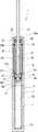
図1、図2は本発明の実施例1に係る液体ダンパー装置を示し、図1は、伸長状態の断面図、図2は、収縮状態の断面図である。[Overall configuration of liquid damper device]
1 and 2 show a liquid damper device according to
本実施例の液体ダンパー装置1は、図1、図2のように、シリンダ3とピストン5とを備えている。 The
前記シリンダ3は、筒状に形成され、内径側に小内径部7と大内径部9とが軸方向に連続して設けられている。 The
前記小内径部7内には、作動液体として例えばシリコーンオイルが封入されている。この小内径部7内には、ピストン5が配置され、シリンダ3内を圧力室11と反圧力室13とに区画している。このピストン5は、圧力室11側及び反圧力室13側間を移動可能とされシリンダ3外部へ突出するピストン・ロッド15を備えている。 In the small
ピストン5には、小内径部7内においてスプリング座17が固定され、このスプリング座17と小内径部7の奥壁面7aとの間には、ピストン5を反圧力室13側に付勢するリターン・スプリング18が配置されている。 A
前記シリンダ3の大内径部9内には、ロッド・ガイド19が反圧力室13側で嵌装されている。ロッド・ガイド19は、中空筒状に形成されており、軸心部に挿通孔21を備えている。挿通孔21は、ロッド・ガイド19の内周側でピストン・ロッド15を貫通させている。ロッド・ガイド19の外周側には、周回状の凹面部23が形成されている。凹面部23内には、独立気泡のゴム等からなるアキュムレータ25が収容されている。 A
前記ロッド・ガイド19の軸方向一端には、フランジ部27が形成され、他端には拡径部29が形成されている。フランジ部27は、反圧力室13側に配置され大内径部9の内周面に嵌合している。このフランジ部27には、凹面部23内を反圧力室13に連通させる連通路27aが貫通形成されている。連通路27aは、シリコーンオイルをロッド・ガイド19の凹面部23内へ導き、この導きによりアキュムレータ25による反圧力室13の容積変化を吸収可能としている。 A
前記他端の拡径部29には、シール収容部29aが設けられ、このシール収容部29a内にはピストン・ロッド15に摺接するUパッキン等からなるシール部材31が嵌合保持されている。また、拡径部29の外周には、周溝29bが形成されている。周溝29b内には、Oリング等からなる密閉用のシール部材33が保持されている。この拡径部29に隣接してシリンダ3の開口端部にキャップ部35が取り付けられ、ロッド・ガイド19の抜け止め等が行われている。
[ピストン]
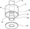
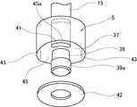
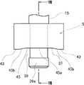
図3は、ピストンと弁体との関係を示す斜視図、図4,図5は、ピストンと弁体との関係を示す分解斜視図、図6は、ピストンの拡大側面図、図7は、ピストンの拡大端面図、図8は、図6のVIII−VIII線矢視断面図である。The
[piston]
3 is a perspective view showing the relationship between the piston and the valve body, FIGS. 4 and 5 are exploded perspective views showing the relationship between the piston and the valve body, FIG. 6 is an enlarged side view of the piston, and FIG. FIG. 8 is an enlarged end view of the piston, and FIG. 8 is a sectional view taken along line VIII-VIII in FIG.
図1〜図8のように、ピストン5の圧力室11側の面37には、中心部に段付きの突軸部39が突設され、この突軸部39の頭部39aに前記スプリング座17が圧入等により固定されている。このスプリング座17とピストン5の面37との間には、隙間40が形成されている。 As shown in FIGS. 1 to 8, the
このピストン5には、複数、例えば一対の流通路41が貫通形成されている。流通路41は、前記圧力室11側及び反圧力室13側に貫通し前記シリコーンオイルを圧力室11側及び反圧力室13側へ移動させて圧力調整を行わせるものである。 A plurality of, for example, a pair of
前記突軸部39には、スプリング座17と面37との間に配置されたドーナツ板形状の弁体42が嵌合している。弁体42は、PET(樹脂材料)等で可撓に形成され外周径は、ピストン5の外周径と同等か僅かに小径に形成されている。 A donut plate-shaped
この弁体42は、前記ピストン5の圧力室11側への移動時に前記流通路41に対する閉じ側へ動作すると共に前記ピストン5の反圧力室13側への移動時に前記流通路41に対する開側へ動作する。 The
前記ピストン5の圧力室11側の面37の外周部に、凸面部43及び凹面部45が形成されている。凸面部43は、ピストン5径方向に対向する2箇所に形成され、前記弁体42の外周部を極部的に2点支持する。 A
また、前記ピストン5の圧力室11側の面37に、前記凸面部43での支持により前記弁体42との間に絞り用の隙間Sを形成可能とする凹面部45が設けられている。凹面部45は、対向する凸面部43間に形成され中間の底部45aに前記流通路41が開口する。 A
本実施例では、ピストン5が突軸部39を備えているため、流通路41は、凹面部45においてピストン5の外周部側に開口している。 In this embodiment, since the
これら凸面部43及び凹面部45間は、曲面45bでなだらかに連続し、凹面部45の底部45aは、平坦に形成されている。但し、底部45aをなだらかな凹曲面等に形成することもできる。
[引き戸]
図9は、本発明実施例の液体ダンパー装置を備えるドア・クローザー引き込みユニットを取り付けた引き戸を示す組み付け図、図10は、引き戸の動作状態に係るドア・クローザー引き込みユニット周辺を示し、(a)は、引き戸引き込み開始状態、(b)は、引き戸全閉状態の拡大図である。Between the
[sliding door]
FIG. 9 is an assembly diagram showing a sliding door to which a door / closer retracting unit including the liquid damper device according to the embodiment of the present invention is attached, and FIG. 10 shows the periphery of the door / closer retracting unit according to the operating state of the sliding door, (a) Is a sliding door retracting start state, (b) is an enlarged view of the sliding door fully closed state.
図9のように、固定側である家屋の開口部51に、可動側である引き戸53が組み付けられ、引き戸53を開口部51に対しスライド移動させることで開口部51を開閉する。 As shown in FIG. 9, the sliding
前記開口部51には、固定側のスライド・レール55が取り付けられ、このスライド・レール55に引き戸53が直線移動可能に支持されている。開口部51には、液体ダンパー装置1を適用したドア・クローザー引き込みユニット57が取り付けられ、このドア・クローザー引き込みユニット57により、引き戸53の全閉直前の所定範囲で引き戸の自動的な引き込みと緩衝とが行われる。 A fixed
図10のように、ドア・クローザー引き込みユニット57は、ハウジング59に可動板61と液体ダンパー装置1とコイル・スプリング63とを備えている。 As shown in FIG. 10, the door /
前記ハウジング59は、開口部51側に固定され、このハウジング59には、ガイド長孔65が設けられている。ガイド長孔65には、可動板61のピン61a,61bが嵌合し、可動板61が図10(a)(b)のように移動可能に支持されている。可動板61には、引き戸53の突部53aを係合させる凹部61cが形成されている。 The
前記液体ダンパー装置1は、ハウジング59に固定支持され、ピストン・ロッド15の先端が可動板61に対向している。 The
前記コイル・スプリング63は、一端が前記可動板61のスプリング係合ピン61dに係合し、他端がハウジング59のスプリング係合ピン59aに係合している。 The
したがって、引き戸53が開状体から人の手により閉じられると、引き戸53が閉まりきる直前に図10(a)の位置で引き戸53の突部53aが可動板61の凹部61cに係合し、可動板61のピン61bのガイド長孔65に対する係合が外れる。 Therefore, when the sliding
この係合の外れにより可動板61がコイル・スプリング63のアシストを受けながら引き戸53と共にガイド長孔65を移動し始め、液体ダンパー装置1のピストン・ロッド15を収縮動作させる。このときのダンピング動作は後述する。
[引き出し]
図11は、本発明実施例の液体ダンパー装置を備える引き込みユニットを取り付けた引き出しを示す組み付け図、図12は、引き込みユニットを示す拡大斜視図である。With this disengagement, the
[drawer]
FIG. 11 is an assembly view showing a drawer to which a pull-in unit including the liquid damper device according to the embodiment of the present invention is attached, and FIG. 12 is an enlarged perspective view showing the pull-in unit.
図11のように、固定側であるキャビネットの開口部71に、可動側である引き出し73が組み付けられ、引き出し73を開口部71に対しスライド移動させることで引き出し73を開口部71内へ収納させる。 As shown in FIG. 11, a movable-
前記開口部71及び引き出し73間には、スライド・レール75が取り付けられ、このスライド・レール75に引き出し73が直線移動可能に支持されている。スライド・レール75は、入れ子式の可動レール部75a,75bを備え、引き出し73に固定された可動レール部75aには、係合部75aaが設けられている。開口部71には、液体ダンパー装置1を適用した引き込みユニット77が取り付けられ、この引き込みユニット77により、引き出し73の全閉直前の所定範囲で引き出し73の自動的な引き込みと緩衝とが行われる。 A
図12のように、引き込みユニット77は、ハウジング79に可動駒81と液体ダンパー装置1と図示しないコイル・スプリングとを備えている。 As shown in FIG. 12, the pull-in
前記ハウジング79は、開口部71側内に固定され、このハウジング79には、ガイド長孔85が設けられている。ガイド長孔85には、可動駒81のピン81a,81bが嵌合し、可動駒81がガイド長孔85に沿って移動可能に支持されている。可動駒81の係合端は、引き出し73側の係合部75aaと係合するようにハウジング79上に突出している。 The
前記液体ダンパー装置1は、ハウジング79に固定支持され、ピストン・ロッドの先端が可動駒81に対向している。 The
前記コイル・スプリングは、図示しないが、一端が前記可動駒81に係合し、他端がハウジング79に係合している。 Although not shown, the coil spring has one end engaged with the
したがって、引き出し73が開状体から人の手により閉じられると、引き出し73が閉まりきる直前に引き出し73側の係合部75aaが可動駒81の先端に係合し、可動駒81のピン81bのガイド長孔85に対する係合が外れる。 Therefore, when the
この係合の外れにより可動駒81がコイル・スプリングのアシストを受けながら引き出し73と共にガイド長孔85を移動し始め、液体ダンパー装置1のピストン・ロッド15を収縮動作させる。このときのダンピング動作は後述する。
[ダンピング動作]
本実施例の液体ダンパー装置1のダンピング動作について、図13〜図15をも参照して説明する。図13〜図15は、ダンパーのピストン及びその周辺構造を示し、図13は、ダンパー静止時におけるピストンおよびその周辺構造の要部拡大断面図、図14は、ピストンが圧力室側へ移動する動作中期から後期における要部拡大断面図、図15は、ピストンが圧力室側へ移動する動作初期から中期における要部拡大断面図であり、それぞれ(a)は、図8に対応する拡大断面図、(b)は、(a)に直交する拡大断面図である。また、図16は、ピストン動作時のピストンの移動速度と抗力との関係を比較例と共に示すグラフである。この場合の比較例は、図17に記載したものを対象としている。
本実施例の液体ダンパー装置1は、前記のように引き戸53(或いは引き出し73)の閉じ動作をダンピングするものとして取り付けられ、この引き戸53(或いは引き出し73)の閉じ動作は、前記のようにスプリングによりアシストするようになっている。With this disengagement, the
[Damping operation]
The damping operation of the
The
したがって、引き戸53(或いは引き出し73)が人の手により閉じられると、引き戸53(或いは引き出し73)が閉まりきる直前に前記のように液体ダンパー装置1が作用を開始する。 Therefore, when the sliding door 53 (or the drawer 73) is closed by a human hand, the
この液体ダンパー装置1の作用によりダンピングが行われると共に、手を離してもスプリングアシストにより引き戸53(或いは引き出し73)は自動的に閉じられることになる。 かかる引き戸53(或いは引き出し73)の閉じ動作が行われ液体ダンパー装置1が作用し始めるとピストン・ロッド15が外力により図2のようにシリンダ3内へ収縮動作する。
このピストン・ロッド15の収縮動作に連動して、ピストン5が圧力室11側へ軸方向移動する。ピストン5が軸方向移動すると弁体42がシリコーンオイルから圧力を受けて閉じ側へ移動する。Damping is performed by the action of the
The
液体ダンパー装置1が作用し始める動作初期〜中期は、引き戸53(或いは引き出し73)の速度が高く高負荷となるため、図15のように抗力が高められ、強いダンピングで引き戸53(或いは引き出し73)を減速させることができる。 Since the sliding door 53 (or the drawer 73) has a high speed and a high load during the operation from the beginning to the middle of the operation of the
すなわち、前記ピストン5の移動速度が速い時は、シリコーンオイルからの圧力により弁体42が凸面部43を支点に凹面部45側へ撓む。したがって、ピストン5の速度に応じて弁体42とピストン5の凹面部45との間の隙間Sが小さくなり、一定以上の速度では弁体42が底部45aに接し、流通路41の開口が閉じられる。 こうして、ピストン5の移動速度が高速である高負荷の動作初期から中期は、ピストンに働く抗力が増大し、強くダンピングさせることができる。
このダンピングにより引き戸53(或いは引き出し73)の減速が行われ、軽負荷になる動作中期から後期は、図14のように弁体42の撓みが復元しほとんど変形することなくピストン5の一対の凸面部43により外周縁部の2箇所が支持される。 このため、弁体42とピストン5の凹面部45との間に隙間Sを生じ、圧力室11側のシリコーンオイルが弁体42とピストン5の凹面部45との間の隙間Sから流通路41を通り、またピストン5の外周面とシリンダ3の内周面との間隙を通って反圧力室13側へ移動し、軽度にダンピングすることができる。That is, when the moving speed of the
Due to this damping, the sliding door 53 (or the drawer 73) is decelerated, and during the middle to late operation when the load is light, the deflection of the
この動作中期から後期の軽度のダンピングと前記動作初期から中期の強いダンピングとにより、引き戸53(或いは引き出し73)の閉じ動作を静かに且つ全体として短い時間で円滑に完了させることができる。
このようなダンピング動作において、本実施例では、弁体42を浅い凹面部45側へ容易に撓ませることができる形態であるため、弁体42の硬さの調節により図16破線間Aにおいて広く特性の調節を行わせることができる。By the mild damping from the middle to the latter period of the operation and the strong damping from the early stage to the middle period, the closing operation of the sliding door 53 (or the drawer 73) can be completed smoothly and smoothly in a short time as a whole.
In such a damping operation, in the present embodiment, since the
これに対し、図17の例では、プレート109(弁体)の内周側が突出部107の周縁角部に支持された状態でプレート109が撓むことになり、プレート109の撓みに要する荷重が大きくなるため、プレート109の硬さ調整による特性の調節代がBと狭くなる。[実施例1の効果]
本発明実施例は、シリコーンオイルを封入したシリンダ3と、このシリンダ3内を圧力室11側と反圧力室13側とに区画し該圧力室11側及び反圧力室13側間を移動可能に配置されシリンダ3外部へ突出するピストン・ロッド15を備えたピストン5と、このピストン5に設けられ前記圧力室11側及び反圧力室13側間を貫通し前記シリコーンオイルを圧力室11側及び反圧力室13側間で移動させて圧力調整を行わせる流通路41と、前記ピストン5の圧力室11側への移動時に前記流通路41に対する閉じ側へ動作すると共に前記ピストン5の反圧力室13側への移動時に前記流通路41に対する開側へ動作する可撓の弁体42とを備えた液体ダンパー装置1であって、前記ピストン5の圧力室11側の面37の外周部に、ピストン5径方向に対向する2箇所で前記弁体42の外周部を2点支持する凸面部43を設け、前記ピストン5の圧力室11側の面37に、前記凸面部43での支持により前記弁体42との間に絞り用の隙間Sを形成可能として前記流通路41が開口する凹面部45を設けた。On the other hand, in the example of FIG. 17, the
In the embodiment of the present invention, a
このため、ピストン5がシリンダ3内の圧力室11側へ移動すると弁体42は、シリコーンオイルの圧力を受けて移動して凸面部43に当接する。この当接により軽負荷の時は、弁体42とピストン5の凹面部45との間に一定の隙間Sを形成することができる。 For this reason, when the
圧力室11内のシリコーンオイルは、弁体42及びピストン5間の隙間Sにより絞られ、流通路41を通って反圧力室13側へ移動することができる。また、シリコーンオイルは、ピストン5の外周面とシリンダ3の内周面との間隙をも通じて、反圧力室13側へ移動することができる。 Silicone oil in the
これらのシリコーンオイルの移動によりシリコーンオイルがピストン5に対して抗力を与え、ピストン5の動作を軽度の抗力でダンピングすることができる。 By the movement of these silicone oils, the silicone oil gives a drag to the
高負荷の時は、弁体42がシリコーンオイルからの圧力により凸面部43間の中間部で撓み、ピストン5の凹面部45の底部45aにも接触する。この接触により流通路41が閉止され、シリコーンオイルの移動は、ほぼピストン5の外周面とシリンダ3の内周面との間隙のみで行われ、ピストン5に対するシリコーンオイルの抗力を高めることができる。 When the load is high, the
したがって、弁体42が流通路41を閉じる場合も弁体42に無理な変形を与えることなく凹面部45に当接することができるため、弁体42の耐久性を向上させることができる。 Therefore, even when the
また、弁体42が流通路41を閉じるために撓むときも、浅い凹面部45に沿って撓むことができ、撓みに必要な力を軽減させることができる。このため、ピストンの移動
速度に対する抗力の関係の調整代Aを比較例の調整代Bに対して広げることができる。
[その他]
凸面部43と凹面部45との間は、必ずしも連続曲面で形成される必要はなく、稜線が存在しても良い。この場合でも、凹面部45に密着する弁体42の外周縁部は、凸面部43から若干浮き上がることになり、弁体42に無理な力は働かない。Moreover, when the
[Others]
It is not always necessary to form a continuous curved surface between the
1 液体ダンパー装置
3 シリンダ
5 ピストン
11 圧力室
13 反圧力室
15 ピストン・ロッド
41 流通路
42 弁体
43 凸面部
45 凹面部
45a 底部
S 隙間DESCRIPTION OF
Claims (3)
Translated fromJapaneseこのシリンダ内を圧力室側と反圧力室側とに区画し該圧力室側及び反圧力室側間を移動可能に配置されシリンダ外部へ突出するピストン・ロッドを備えたピストンと、
このピストンに設けられ前記圧力室側及び反圧力室側に貫通し前記作動液体を圧力室側及び反圧力室側に移動させる流通路と、
前記ピストンの圧力室側への移動時に前記流通路に対する閉じ側へ動作すると共に前記ピストンの反圧力室側への移動時に前記流通路に対する開側へ動作する可撓の弁体と、
を備えた液体ダンパー装置であって、
前記ピストンの圧力室側の面の外周部に、前記弁体の外周部を支持する凸面部を設け、
前記ピストンの圧力室側の面に、前記凸面部での支持により前記弁体との間に絞り用の隙間を形成可能として前記流通路が開口する凹面部を設け、
前記凸面部及び凹面部間は、曲面で連続し、
前記曲面は、前記凸面部及び凹面部に角部を有することなくなだらかに連続し、
前記弁体が閉じ側へ動作したとき前記凸面部に支持されながら前記凹面部に沿って撓み前記流通路を閉止可能である、
ことを特徴とする液体ダンパー装置。A cylinder filled with working fluid;
A piston provided with a piston rod that divides the inside of the cylinder into a pressure chamber side and a counter pressure chamber side and is arranged so as to be movable between the pressure chamber side and the counter pressure chamber side;
A flow passage provided in the piston and penetrating the pressure chamber side and the counter pressure chamber side to move the working liquid to the pressure chamber side and the counter pressure chamber side;
A flexible valve element that operates toward the closing side with respect to the flow path when the piston moves toward the pressure chamber and operates toward the opening side with respect to the flow path when the piston moves toward the counter pressure chamber;
A liquid damper device comprising:
Provided on the outer peripheral portion of the pressure chamber side surface of the piston is a convex surface portion that supports the outer peripheral portion of the valve body,
On the surface on the pressure chamber side of the piston, a concave surface portion is providedin which the flow passage opens so that a throttling gap can be formed between the valve body and the valve body by support by the convex surface portion.
The convex portion and the concave portion are continuous with a curved surface,
The curved surface is gently continuous without having corners on the convex and concave portions,
When the valve body is moved to the closed side, the flow passage can be closed while being bent along the concave surface portion while being supported by the convex surface portion.
A liquid damper device.
前記凸面部は、前記ピストン径方向に対向する2箇所で前記弁体の外周部を極部的に支持し、
前記凹面部は、前記2箇所の凸面部間に形成された、
ことを特徴とする液体ダンパー装置。The liquid damper device according to claim 1,
The convex surface portion supports the outer peripheral portion of the valve body at two locations opposed to the piston radial direction,
The concave surface portion is formed between the two convex surface portions,
A liquid damper device.
前記凹面部の底部は、平坦面に形成され、
この平坦面に前記流通路が開口する、
ことを特徴とする液体ダンパー装置。The liquid damper device according to claim 1 or 2,
The bottom of the concave portion is formed on a flat surface,
The flow passage opens on this flat surface,
A liquid damper device.
Priority Applications (5)
| Application Number | Priority Date | Filing Date | Title |
|---|---|---|---|
| JP2009193546AJP5542390B2 (en) | 2009-08-24 | 2009-08-24 | Liquid damper device |
| HK12108574.3AHK1167883B (en) | 2009-08-24 | 2010-06-10 | Liquid damper device |
| EP10811418.2AEP2472140B1 (en) | 2009-08-24 | 2010-06-10 | Liquid damper device |
| PCT/JP2010/003886WO2011024359A1 (en) | 2009-08-24 | 2010-06-10 | Liquid damper device |
| CN201080037532.2ACN102483121B (en) | 2009-08-24 | 2010-06-10 | liquid buffer device |
Applications Claiming Priority (1)
| Application Number | Priority Date | Filing Date | Title |
|---|---|---|---|
| JP2009193546AJP5542390B2 (en) | 2009-08-24 | 2009-08-24 | Liquid damper device |
Publications (2)
| Publication Number | Publication Date |
|---|---|
| JP2011043231A JP2011043231A (en) | 2011-03-03 |
| JP5542390B2true JP5542390B2 (en) | 2014-07-09 |
Family
ID=43627482
Family Applications (1)
| Application Number | Title | Priority Date | Filing Date |
|---|---|---|---|
| JP2009193546AActiveJP5542390B2 (en) | 2009-08-24 | 2009-08-24 | Liquid damper device |
Country Status (4)
| Country | Link |
|---|---|
| EP (1) | EP2472140B1 (en) |
| JP (1) | JP5542390B2 (en) |
| CN (1) | CN102483121B (en) |
| WO (1) | WO2011024359A1 (en) |
Families Citing this family (8)
| Publication number | Priority date | Publication date | Assignee | Title |
|---|---|---|---|---|
| JP5767005B2 (en)* | 2011-04-20 | 2015-08-19 | Ntn株式会社 | Hydraulic auto tensioner assembly method |
| AT513330B1 (en)* | 2012-08-27 | 2017-04-15 | Blum Gmbh Julius | Damping device for movable furniture parts |
| TR201705069A2 (en)* | 2017-04-05 | 2018-10-22 | Celikform Gestamp Otomotiv Anonim Sirketi | Sliding Door Lock Mechanism for Automotive Industry |
| TWI641342B (en) | 2017-11-06 | 2018-11-21 | King Slide Works Co., Ltd. | Buffer device and furniture piece including the same |
| TWI645811B (en) | 2017-11-06 | 2019-01-01 | 川湖科技股份有限公司 | Movable furniture part and damping device thereof |
| DE102017010876B4 (en) | 2017-11-24 | 2023-06-01 | Günther Zimmer | Cylinder-piston unit with load-dependent throttle |
| DE102019008572B4 (en) | 2019-12-10 | 2021-09-16 | Günther Zimmer | Sliding door system |
| GB2616911A (en) | 2022-03-25 | 2023-09-27 | Titus D O O Dekani | Damper with tiered response |
Family Cites Families (8)
| Publication number | Priority date | Publication date | Assignee | Title |
|---|---|---|---|---|
| JPS4523099Y1 (en)* | 1969-01-08 | 1970-09-11 | ||
| ES2115429B1 (en)* | 1993-05-10 | 1999-02-16 | Fichtel & Sachs Ag | VALVE FOR A HYDRAULIC TELESCOPIC VIBRATION DAMPER. |
| FR2751713B1 (en)* | 1996-07-24 | 1998-09-18 | Donerre Amortisseur Soc | OIL SHOCK ABSORBER SYSTEM |
| JPH11280819A (en)* | 1998-01-29 | 1999-10-15 | Toyota Motor Corp | Shock absorber |
| JP2005299791A (en)* | 2004-04-12 | 2005-10-27 | Kayaba Ind Co Ltd | Shock absorber damping valve |
| JP2008057685A (en)* | 2006-08-31 | 2008-03-13 | Hitachi Ltd | Hydraulic shock absorber |
| JP4895953B2 (en)* | 2007-09-19 | 2012-03-14 | 不二ラテックス株式会社 | Liquid damper device |
| SE0702798L (en)* | 2007-12-14 | 2009-04-28 | Oehlins Racing Ab | Shock absorbers with increasing damping force |
- 2009
- 2009-08-24JPJP2009193546Apatent/JP5542390B2/enactiveActive
- 2010
- 2010-06-10EPEP10811418.2Apatent/EP2472140B1/enactiveActive
- 2010-06-10CNCN201080037532.2Apatent/CN102483121B/enactiveActive
- 2010-06-10WOPCT/JP2010/003886patent/WO2011024359A1/enactiveApplication Filing
Also Published As
| Publication number | Publication date |
|---|---|
| EP2472140B1 (en) | 2019-07-24 |
| CN102483121A (en) | 2012-05-30 |
| CN102483121B (en) | 2014-05-07 |
| WO2011024359A1 (en) | 2011-03-03 |
| HK1167883A1 (en) | 2012-12-14 |
| EP2472140A4 (en) | 2018-01-10 |
| JP2011043231A (en) | 2011-03-03 |
| EP2472140A1 (en) | 2012-07-04 |
Similar Documents
| Publication | Publication Date | Title |
|---|---|---|
| JP5542390B2 (en) | Liquid damper device | |
| JP6013333B2 (en) | Furniture hinges | |
| US6802408B2 (en) | Fluid damper, particularly for movable pieces of furniture | |
| EP3480401B1 (en) | Furniture part and damping device thereof | |
| JP5270376B2 (en) | Furniture damper | |
| JP7206003B2 (en) | damper | |
| KR101666780B1 (en) | Damper for furniture | |
| TWI641342B (en) | Buffer device and furniture piece including the same | |
| EP2546443A1 (en) | Door damper buffer | |
| CN209875830U (en) | Furniture bumpers and furniture accessories | |
| JP6864602B2 (en) | Floor hinge | |
| JP2009133460A (en) | Fluid damper | |
| JP7508687B2 (en) | Furniture Damper | |
| JP2007046729A (en) | Fluid damper | |
| KR20150012618A (en) | Door damper for shock absorption | |
| TWI516689B (en) | Liquid dampers | |
| JP5004568B2 (en) | shock absorber | |
| HK1167883B (en) | Liquid damper device | |
| JP5322678B2 (en) | shock absorber | |
| JP7696057B2 (en) | Damper | |
| JP7721813B2 (en) | Damper for a fitting for movably supporting a swivel or pull-out element | |
| CN109770587B (en) | Buffer device and furniture piece including the same | |
| CN109770586B (en) | Movable furniture part and buffer device thereof | |
| KR20170014908A (en) | Buffer for hinge of furnitures | |
| JP2009265893A (en) | Decompression valve |
Legal Events
| Date | Code | Title | Description |
|---|---|---|---|
| A621 | Written request for application examination | Free format text:JAPANESE INTERMEDIATE CODE: A621 Effective date:20120621 | |
| A131 | Notification of reasons for refusal | Free format text:JAPANESE INTERMEDIATE CODE: A131 Effective date:20131015 | |
| A521 | Request for written amendment filed | Free format text:JAPANESE INTERMEDIATE CODE: A523 Effective date:20131209 | |
| TRDD | Decision of grant or rejection written | ||
| A01 | Written decision to grant a patent or to grant a registration (utility model) | Free format text:JAPANESE INTERMEDIATE CODE: A01 Effective date:20140422 | |
| A61 | First payment of annual fees (during grant procedure) | Free format text:JAPANESE INTERMEDIATE CODE: A61 Effective date:20140507 | |
| R150 | Certificate of patent or registration of utility model | Ref document number:5542390 Country of ref document:JP Free format text:JAPANESE INTERMEDIATE CODE: R150 | |
| R250 | Receipt of annual fees | Free format text:JAPANESE INTERMEDIATE CODE: R250 | |
| R250 | Receipt of annual fees | Free format text:JAPANESE INTERMEDIATE CODE: R250 | |
| R250 | Receipt of annual fees | Free format text:JAPANESE INTERMEDIATE CODE: R250 | |
| R250 | Receipt of annual fees | Free format text:JAPANESE INTERMEDIATE CODE: R250 | |
| R250 | Receipt of annual fees | Free format text:JAPANESE INTERMEDIATE CODE: R250 | |
| R250 | Receipt of annual fees | Free format text:JAPANESE INTERMEDIATE CODE: R250 | |
| R250 | Receipt of annual fees | Free format text:JAPANESE INTERMEDIATE CODE: R250 | |
| R250 | Receipt of annual fees | Free format text:JAPANESE INTERMEDIATE CODE: R250 | |
| R250 | Receipt of annual fees | Free format text:JAPANESE INTERMEDIATE CODE: R250 |