JP5542217B2 - MRI conditional and safe lead with multilayer conductor - Google Patents
MRI conditional and safe lead with multilayer conductorDownload PDFInfo
- Publication number
- JP5542217B2 JP5542217B2JP2012547075AJP2012547075AJP5542217B2JP 5542217 B2JP5542217 B2JP 5542217B2JP 2012547075 AJP2012547075 AJP 2012547075AJP 2012547075 AJP2012547075 AJP 2012547075AJP 5542217 B2JP5542217 B2JP 5542217B2
- Authority
- JP
- Japan
- Prior art keywords
- coil
- lead
- coil conductor
- layer
- wire
- Prior art date
- Legal status (The legal status is an assumption and is not a legal conclusion. Google has not performed a legal analysis and makes no representation as to the accuracy of the status listed.)
- Expired - Fee Related
Links
- 239000004020conductorSubstances0.000titleclaimsdescription132
- 239000011810insulating materialSubstances0.000claimsdescription7
- BQCADISMDOOEFD-UHFFFAOYSA-NSilverChemical group[Ag]BQCADISMDOOEFD-UHFFFAOYSA-N0.000claimsdescription3
- 229910001182Mo alloyInorganic materials0.000claimsdescription2
- QZYDAIMOJUSSFT-UHFFFAOYSA-N[Co].[Ni].[Mo]Chemical compound[Co].[Ni].[Mo]QZYDAIMOJUSSFT-UHFFFAOYSA-N0.000claimsdescription2
- 239000011248coating agentSubstances0.000claimsdescription2
- 238000000576coating methodMethods0.000claimsdescription2
- 239000010410layerSubstances0.000description82
- 238000002595magnetic resonance imagingMethods0.000description31
- 230000035939shockEffects0.000description9
- 238000013461designMethods0.000description7
- 239000000463materialSubstances0.000description7
- 238000000034methodMethods0.000description7
- 230000000747cardiac effectEffects0.000description6
- 238000009125cardiac resynchronization therapyMethods0.000description6
- 238000010586diagramMethods0.000description6
- 230000033764rhythmic processEffects0.000description5
- 238000002560therapeutic procedureMethods0.000description5
- 230000008859changeEffects0.000description4
- 230000005684electric fieldEffects0.000description4
- 229920000642polymerPolymers0.000description4
- 230000005855radiationEffects0.000description4
- 230000001225therapeutic effectEffects0.000description4
- 208000001871TachycardiaDiseases0.000description3
- 238000004891communicationMethods0.000description3
- 230000000694effectsEffects0.000description3
- 230000005672electromagnetic fieldEffects0.000description3
- 238000012986modificationMethods0.000description3
- 230000004048modificationEffects0.000description3
- GUVRBAGPIYLISA-UHFFFAOYSA-Ntantalum atomChemical compound[Ta]GUVRBAGPIYLISA-UHFFFAOYSA-N0.000description3
- 238000011282treatmentMethods0.000description3
- KDLHZDBZIXYQEI-UHFFFAOYSA-NPalladiumChemical compound[Pd]KDLHZDBZIXYQEI-UHFFFAOYSA-N0.000description2
- VYPSYNLAJGMNEJ-UHFFFAOYSA-NSilicium dioxideChemical compoundO=[Si]=OVYPSYNLAJGMNEJ-UHFFFAOYSA-N0.000description2
- 210000001015abdomenAnatomy0.000description2
- 206010003119arrhythmiaDiseases0.000description2
- 238000010276constructionMethods0.000description2
- 229920001577copolymerPolymers0.000description2
- 229920000840ethylene tetrafluoroethylene copolymerPolymers0.000description2
- 229920000295expanded polytetrafluoroethylenePolymers0.000description2
- 210000002837heart atriumAnatomy0.000description2
- 230000001939inductive effectEffects0.000description2
- 238000007689inspectionMethods0.000description2
- 230000007246mechanismEffects0.000description2
- BASFCYQUMIYNBI-UHFFFAOYSA-NplatinumChemical compound[Pt]BASFCYQUMIYNBI-UHFFFAOYSA-N0.000description2
- -1polytetrafluoroethylenePolymers0.000description2
- 229920001343polytetrafluoroethylenePolymers0.000description2
- 239000004810polytetrafluoroethyleneSubstances0.000description2
- 230000004044responseEffects0.000description2
- 210000005245right atriumAnatomy0.000description2
- 210000005241right ventricleAnatomy0.000description2
- 239000002356single layerSubstances0.000description2
- 229910052715tantalumInorganic materials0.000description2
- 208000003663ventricular fibrillationDiseases0.000description2
- 238000004804windingMethods0.000description2
- 238000005481NMR spectroscopyMethods0.000description1
- RTAQQCXQSZGOHL-UHFFFAOYSA-NTitaniumChemical compound[Ti]RTAQQCXQSZGOHL-UHFFFAOYSA-N0.000description1
- 238000007792additionMethods0.000description1
- 229910045601alloyInorganic materials0.000description1
- 239000000956alloySubstances0.000description1
- 230000000712assemblyEffects0.000description1
- 238000000429assemblyMethods0.000description1
- 230000004323axial lengthEffects0.000description1
- 238000005452bendingMethods0.000description1
- 230000005540biological transmissionEffects0.000description1
- 239000008280bloodSubstances0.000description1
- 210000004369bloodAnatomy0.000description1
- 230000017531blood circulationEffects0.000description1
- 230000008878couplingEffects0.000description1
- 238000010168coupling processMethods0.000description1
- 238000005859coupling reactionMethods0.000description1
- 230000003247decreasing effectEffects0.000description1
- 230000005670electromagnetic radiationEffects0.000description1
- 229910000701elgiloys (Co-Cr-Ni Alloy)Inorganic materials0.000description1
- QHSJIZLJUFMIFP-UHFFFAOYSA-Nethene;1,1,2,2-tetrafluoroetheneChemical groupC=C.FC(F)=C(F)FQHSJIZLJUFMIFP-UHFFFAOYSA-N0.000description1
- 238000003384imaging methodMethods0.000description1
- 238000003780insertionMethods0.000description1
- 230000037431insertionEffects0.000description1
- 229910052741iridiumInorganic materials0.000description1
- GKOZUEZYRPOHIO-UHFFFAOYSA-Niridium atomChemical compound[Ir]GKOZUEZYRPOHIO-UHFFFAOYSA-N0.000description1
- 230000001788irregularEffects0.000description1
- 210000005246left atriumAnatomy0.000description1
- 210000005240left ventricleAnatomy0.000description1
- 230000005923long-lasting effectEffects0.000description1
- 238000004519manufacturing processMethods0.000description1
- 238000005259measurementMethods0.000description1
- 238000012806monitoring deviceMethods0.000description1
- 229910052763palladiumInorganic materials0.000description1
- 229910052697platinumInorganic materials0.000description1
- 229920001296polysiloxanePolymers0.000description1
- 229920002635polyurethanePolymers0.000description1
- 239000004814polyurethaneSubstances0.000description1
- 230000009467reductionEffects0.000description1
- 238000010008shearingMethods0.000description1
- 238000002633shock therapyMethods0.000description1
- 229920005573silicon-containing polymerPolymers0.000description1
- 239000010971silver fillSubstances0.000description1
- 229910001220stainless steelInorganic materials0.000description1
- 239000010935stainless steelSubstances0.000description1
- 230000000638stimulationEffects0.000description1
- 230000000213tachycardiac effectEffects0.000description1
- 229910052719titaniumInorganic materials0.000description1
- 239000010936titaniumSubstances0.000description1
- 238000012546transferMethods0.000description1
- WFKWXMTUELFFGS-UHFFFAOYSA-NtungstenChemical compound[W]WFKWXMTUELFFGS-UHFFFAOYSA-N0.000description1
- 229910052721tungstenInorganic materials0.000description1
- 239000010937tungstenSubstances0.000description1
- 230000002861ventricularEffects0.000description1
Images


Classifications
- A—HUMAN NECESSITIES
- A61—MEDICAL OR VETERINARY SCIENCE; HYGIENE
- A61N—ELECTROTHERAPY; MAGNETOTHERAPY; RADIATION THERAPY; ULTRASOUND THERAPY
- A61N1/00—Electrotherapy; Circuits therefor
- A61N1/02—Details
- A61N1/04—Electrodes
- A61N1/05—Electrodes for implantation or insertion into the body, e.g. heart electrode
- A61N1/056—Transvascular endocardial electrode systems
- A—HUMAN NECESSITIES
- A61—MEDICAL OR VETERINARY SCIENCE; HYGIENE
- A61N—ELECTROTHERAPY; MAGNETOTHERAPY; RADIATION THERAPY; ULTRASOUND THERAPY
- A61N1/00—Electrotherapy; Circuits therefor
- A61N1/02—Details
- A61N1/08—Arrangements or circuits for monitoring, protecting, controlling or indicating
- A61N1/086—Magnetic resonance imaging [MRI] compatible leads
Landscapes
- Health & Medical Sciences (AREA)
- Radiology & Medical Imaging (AREA)
- Heart & Thoracic Surgery (AREA)
- Engineering & Computer Science (AREA)
- Biomedical Technology (AREA)
- Nuclear Medicine, Radiotherapy & Molecular Imaging (AREA)
- Life Sciences & Earth Sciences (AREA)
- Animal Behavior & Ethology (AREA)
- General Health & Medical Sciences (AREA)
- Public Health (AREA)
- Veterinary Medicine (AREA)
- Cardiology (AREA)
- Electrotherapy Devices (AREA)
- Neurology (AREA)
Description
Translated fromJapanese本発明の様々な実施形態は、一般に、植込み可能な医療装置に関する。より詳細には、本発明の実施形態は、MRIの条件付きで安全なリード導体に関する。 Various embodiments of the present invention generally relate to implantable medical devices. More particularly, embodiments of the present invention relate to MRI conditional and safe lead conductors.
適切に機能している場合、人間の心臓は、それ自体の固有のリズムを維持し、体の循環系を通して適切な量の血液をポンプ送りすることができる。しかし、心臓不整脈と呼ばれる不規則な心臓のリズムを有する人もあり、血液循環および心臓出力が減少することになりうる。心臓不整脈を治療する1方法は、ペースメーカーなどのパルス発生器(PG)、植込み型除細動器(ICD)、または心臓再同期(CRT)装置の使用を含む。このような装置は、通常、心臓に対してペーシング治療、および/または電気ショックを施すために用いることのできる1または複数の電極を有するいくつかの導電性リードに結合される。例えば、房室(AV)ペーシングでは、リードは、通常、心臓の心室および心房中に配置され、また胸部もしくは腹部に植え込まれるペースメーカーもしくは除細動器にリード端末のピンを介して取り付けられる。 When functioning properly, the human heart can maintain its own rhythm and pump an appropriate amount of blood through the body's circulatory system. However, some people have irregular heart rhythms called cardiac arrhythmias, which can lead to decreased blood circulation and cardiac output. One method of treating cardiac arrhythmias involves the use of a pulse generator (PG) such as a pacemaker, an implantable cardioverter defibrillator (ICD), or a cardiac resynchronization (CRT) device. Such devices are typically coupled to several conductive leads having one or more electrodes that can be used to apply pacing therapy and / or electric shock to the heart. For example, in atrioventricular (AV) pacing, the lead is typically placed in the ventricle and atrium of the heart and attached to a pacemaker or defibrillator implanted in the chest or abdomen via a lead terminal pin.
磁気共鳴撮像法(MRI)は、患者の体内の画像を表現するために核磁気共鳴技法を利用する非侵襲性の撮像手法である。通常、MRIシステムは、約0.2から3テスラの間の磁場強度を有する磁気コイルを使用する。操作中、体組織は、磁場に直角な平面で、電磁エネルギーの高周波(RF)パルスに一時的に曝される。これらのパルスから得られた電磁エネルギーは、組織中で励起された原子核の緩和特性を測定することによって体組織を画像化するために使用されうる。或る場合には、患者の胸部領域を画像化することが臨床的に見て有利でありうる。胸部MRI手法では、植え込まれたパルス発生器およびリードもまた、印加される電磁場に曝される可能性がある。 Magnetic resonance imaging (MRI) is a non-invasive imaging technique that utilizes nuclear magnetic resonance techniques to represent images within a patient's body. Typically, MRI systems use a magnetic coil having a magnetic field strength between about 0.2 and 3 Tesla. During operation, body tissue is temporarily exposed to radio frequency (RF) pulses of electromagnetic energy in a plane perpendicular to the magnetic field. The electromagnetic energy obtained from these pulses can be used to image body tissue by measuring the relaxation properties of nuclei excited in the tissue. In some cases, it may be clinically advantageous to image the patient's chest region. In a chest MRI procedure, the implanted pulse generator and lead can also be exposed to an applied electromagnetic field.
本発明の様々な実施形態は、MRI放射に曝されたとき、温度上昇を最小化するように構成された多層導体コイルを含む植込み可能な医療用の電気的リードに関する。
例1では、植込み可能な電気的リードは、可撓性の本体、コネクタ組立体、電極、および多層コイル導体からなる。可撓性の本体は、近位端を含む近位領域と、遠位領域と、近位端から遠位領域を通って延びる長手方向の本体管腔とを有する。コネクタ組立体は、植込み可能な電気的リードを植込み可能なパルス発生器に機械的かつ電気的に接続するように構成される。電極は、遠位領域で可撓性の本体に結合され、また多層のコイル導体は、長手方向の本体管腔内で、コネクタ組立体から少なくとも1つの電極へと延びる。多層のコイル導体は、近接したピッチを有するように巻回された1または複数の電線(filars)を含む第1のコイル層と、近接したピッチを有するように巻回された1または複数の電線を含む、第1のコイル層の周囲に配置された第2のコイル層とを含む。第2のコイル層の電線は、第1のコイル層の電線と同じピッチ方向に巻回される。第1および第2のコイル層は、互いに電気的に結合され、また多層のコイル導体が、約3から3.5オームの最大DC抵抗を有するように、コネクタ組立体と電極の間に並列な導電性の経路を設けるように構成される。Various embodiments of the invention relate to an implantable medical electrical lead that includes a multi-layer conductor coil configured to minimize temperature rise when exposed to MRI radiation.
In Example 1, the implantable electrical lead consists of a flexible body, a connector assembly, electrodes, and a multilayer coil conductor. The flexible body has a proximal region including a proximal end, a distal region, and a longitudinal body lumen extending from the proximal end through the distal region. The connector assembly is configured to mechanically and electrically connect the implantable electrical lead to the implantable pulse generator. The electrodes are coupled to the flexible body at the distal region, and the multilayer coil conductor extends from the connector assembly to the at least one electrode within the longitudinal body lumen. The multi-layer coil conductor includes a first coil layer including one or more wires wound with a close pitch and one or more wires wound with a close pitch. And a second coil layer disposed around the first coil layer. The electric wire of the second coil layer is wound in the same pitch direction as the electric wire of the first coil layer. The first and second coil layers are electrically coupled together and in parallel between the connector assembly and the electrodes such that the multilayer coil conductor has a maximum DC resistance of about 3 to 3.5 ohms. It is configured to provide a conductive path.
例2は、例1の植込み可能な電気的リードであり、第1のコイル層および第2のコイル層の電線が個々に電気的に絶縁されている。
例3は、例1または例2の植込み可能な電気的リードであり、第1のコイル層の1または複数の電線が、互いに電気的に絶縁されておらず、また第2のコイル層の1または複数の電線が、互いに電気的に絶縁されておらず、さらに、リードは、第1のコイル層と第2のコイル層の間に少なくとも部分的に配置された絶縁材料の層を含んでいる。Example 2 is the implantable electrical lead of Example 1, where the wires of the first coil layer and the second coil layer are individually electrically isolated.
Example 3 is the implantable electrical lead of Example 1 or Example 2, wherein one or more wires of the first coil layer are not electrically isolated from each other and 1 of the second coil layer. Alternatively, the plurality of electrical wires are not electrically isolated from each other, and the lead further includes a layer of insulating material disposed at least partially between the first coil layer and the second coil layer. .
例4は、例1から例3のいずれかの植込み可能な電気的リードであり、第1および第2のコイル層の1または複数の電線が、銀のコア、およびコバルト・ニッケル・モリブデン合金の外側被覆を含む引抜き充填管(DFT(登録商標):drawn filled tube)ワイヤから製作される。 Example 4 is the implantable electrical lead of any of Examples 1 to 3, wherein the one or more wires of the first and second coil layers are of a silver core and a cobalt-nickel-molybdenum alloy. Made from a drawn filled tube (DFT®) wire with an outer coating.
例5は、例1から例4のいずれかの植込み可能なリードであり、第1のコイル層の電線は、最大で約0.00254センチメートル(0.001インチ)の電線太さ(filar thickness)を有し、また第2のコイル層の電線は、最大で約0.00762センチメートル(0.003インチ)の電線太さを有する。 Example 5 is the implantable lead of any of Examples 1 to 4, wherein the first coil layer wire has a maximum thickness of about 0.001 inch. And the second coil layer wire has a wire thickness of at most about 0.003 inches.
例6では、例1から例5のいずれかの植込み可能な電気的リードが、近接したピッチで、かつ第1および第2のコイル層の電線と同じピッチ方向に巻回された1または複数の電線を含む、第2のコイル層の周囲に配置された第3のコイル層をさらに備える。 In Example 6, one or more implantable electrical leads of any of Examples 1-5 are wound at a close pitch and in the same pitch direction as the wires of the first and second coil layers. It further includes a third coil layer disposed around the second coil layer including the electric wire.
例7は、例1から例6のいずれかの植込み可能なリードであり、第3のコイル層は、最大で約0.01016センチメートル(0.004インチ)の電線太さを有する。
例8は、例1から例7のいずれかの植込み可能な電気的リードであり、第1のコイル層、第2のコイル層、および第3のコイル層のインダクタンスが異なっている。Example 7 is the implantable lead of any of Examples 1-6, and the third coil layer has a wire thickness of up to about 0.004 inches.
Example 8 is the implantable electrical lead of any of Examples 1-7, wherein the inductances of the first coil layer, the second coil layer, and the third coil layer are different.
例9は、例1から例8のいずれかの植込み可能な電気的リードであり、第1のコイル層および第2のコイル層は1電線、2電線、3電線、または4電線の構成(4−filar
construction)を有する。Example 9 is the implantable electrical lead of any of Examples 1-8, wherein the first coil layer and the second coil layer are configured with one wire, two wires, three wires, or four wires (4 -Filer
(construction).
例10は、例1から例9のいずれかの植込み可能な電気的リードであり、第1のコイル層は、両端を含めて、0.00254センチメートル(0.001インチ)と0.00508センチメートル(0.002インチ)の間の電線太さを有する。 Example 10 is the implantable electrical lead of any of Examples 1-9, wherein the first coil layer includes 0.00254 inches (0.001 inch) and 0.00508 cm, including both ends. Has a wire thickness between meters (0.002 inches).
例11は、例1から例9のいずれかの植込み可能な電気的リードであり、第1のコイル層は、1から4電線の構成を備えた0.00178センチメートル(0.0007インチ)太さの引抜き充填管(DFT(登録商標))ワイヤから形成され、また第1のコイル層の外径は0.01016センチメートル(0.004インチ)未満である。 Example 11 is the implantable electrical lead of any of Examples 1-9, wherein the first coil layer is 0.00178 centimeters (0.0007 inches) thick with 1 to 4 wire configurations. The outer diameter of the first coil layer is less than 0.004 inches, and is formed from a drawn and filled tube (DFT®) wire.
例12は、例1から例11のいずれかの植込み可能な電気的リードであり、第2のコイル層は、両端を含めて、0.00178センチメートル(0.0007インチ)から0.00762センチメートル(0.003インチ)の間の電線太さを有する。 Example 12 is the implantable electrical lead of any of Examples 1-11, and the second coil layer includes 0.00178 inches (0.0007 inches) to 0.00762 cm, including both ends. It has a wire thickness between meters (0.003 inches).
例13では、植込み可能な医療リードは、可撓性の本体、コネクタ組立体、電極、および多層のコイル導体からなる。可撓性の本体は、近位端を含む近位領域と、遠位領域と、近位端から遠位領域を通って延びる長手方向の本体管腔とを有する。コネクタ組立体は、植込み可能な医療用リードを植込み可能なパルス発生器に機械的かつ電気的に接続するように構成される。電極は、遠位領域で可撓性の本体に結合され、また多層のコイル導体は、長手方向の本体管腔内でコネクタ組立体から少なくとも電極へと延びる。多層のコイル
導体は、外径(OD)、近接したピッチ、および時計方向もしくは反時計方向の内側コイルピッチ方向を有する内側コイル導体を含む。多層のコイル導体は、近接したピッチ、内側コイルのピッチ方向と同じ中間コイルのピッチ方向、内側コイル導体のODよりも大きい内径(ID)を有する中間コイル導体をさらに含み、中間コイル導体は、内側コイル導体の長さに沿って、内側コイル導体の周囲を半径方向に囲む。多層のコイル導体はまた、近接したピッチを有し、内側コイルのピッチ方向と同じ外側コイルのピッチ方向を備える、中間コイルを半径方向に囲む外側コイル導体を含む。内側コイル導体、中間コイル導体、および外側コイル導体は、電気的に並列に結合されて約3.5オームのDC抵抗が得られる。In Example 13, an implantable medical lead consists of a flexible body, a connector assembly, electrodes, and a multilayer coil conductor. The flexible body has a proximal region including a proximal end, a distal region, and a longitudinal body lumen extending from the proximal end through the distal region. The connector assembly is configured to mechanically and electrically connect the implantable medical lead to the implantable pulse generator. The electrode is coupled to the flexible body at the distal region, and the multilayer coil conductor extends from the connector assembly to at least the electrode within the longitudinal body lumen. The multilayer coil conductor includes an inner coil conductor having an outer diameter (OD), a close pitch, and a clockwise or counterclockwise inner coil pitch direction. The multilayer coil conductor further includes an intermediate coil conductor having a close pitch, a pitch direction of the intermediate coil that is the same as the pitch direction of the inner coil, and an inner diameter (ID) that is greater than the OD of the inner coil conductor, The inner coil conductor is radially surrounded along the length of the coil conductor. The multilayer coil conductor also includes an outer coil conductor having a close pitch and radially surrounding the intermediate coil with the same outer coil pitch direction as the inner coil pitch direction. The inner coil conductor, middle coil conductor, and outer coil conductor are electrically coupled in parallel to provide a DC resistance of about 3.5 ohms.
例14は、例13の植込み可能な医療用リードであり、医療用リードは、内側コイル導体、中間コイル導体、または外側コイル導体のうちの1または複数のものを囲む絶縁材料の1または複数の層をさらに含む。 Example 14 is the implantable medical lead of Example 13, wherein the medical lead is one or more of an insulating material surrounding one or more of the inner coil conductor, intermediate coil conductor, or outer coil conductor. It further includes a layer.
例15は、例13または例14の植込み可能な医療用リードであり、内側コイル導体、中間コイル導体、または外側コイル導体は、1から4電線の構成を有し、それぞれが異なるピッチを有する。 Example 15 is the implantable medical lead of Example 13 or Example 14, wherein the inner coil conductor, intermediate coil conductor, or outer coil conductor has a 1 to 4 wire configuration, each having a different pitch.
例16は、例13から例15のいずれかの植込み可能な医療用リードであり、内側コイル導体は、0.00254センチメートル(0.001インチ)以下のワイヤ直径を有する。 Example 16 is the implantable medical lead of any of Examples 13-15, wherein the inner coil conductor has a wire diameter of 0.00254 inches or less.
例17は、例13から例16のいずれかの植込み可能な医療用リードであり、内側コイル導体は、1〜4電線の組立体を備える0.00178センチメートル(0.0007インチ)の引抜き充填管(DFT(登録商標))ワイヤから形成され、0.01016センチメートル(0.004インチ)未満のODを有する。 Example 17 is the implantable medical lead of any of Examples 13-16, wherein the inner coil conductor is a 0.00178 inch draw fill with an assembly of 1-4 wires. Formed from tube (DFT®) wire and has an OD of less than 0.004 inches.
例18は、例13から例17のいずれかの植込み可能な医療用リードであり、外側コイル導体は、両端を含めて、0.00178センチメートル(0.0007インチ)から0.00762センチメートル(0.003インチ)の間のワイヤ直径を有する。 Example 18 is the implantable medical lead of any of Examples 13 to 17, wherein the outer coil conductor includes 0.00178 inches (0.0007 inches) to 0.00762 cm (including both ends). Having a wire diameter between 0.003 inches).
例19は、例13から例18のいずれかの植込み可能な医療用リードであり、内側コイル層、中間コイル層、および外側コイル層の電線のそれぞれは、個々に絶縁される。 Example 19 is the implantable medical lead of any of Examples 13-18, wherein each of the inner coil layer, intermediate coil layer, and outer coil layer wires are individually insulated.
図面は、必ずしも縮尺を合わせて描かれていない。例えば、図における要素の或る寸法を、本発明の諸実施形態の理解を向上させるために拡大また縮小することもありうる。本発明は、様々な変更形態および代替形態に適用できるが、図面には、例として特定の実施
形態が示されており、それを以下で詳細に説明する。しかし、本発明を、記載された特定の実施形態に限定するものではないことが意図されている。それとは反対に、本発明は、添付の特許請求の範囲で定義される本発明の範囲に含まれるすべての変更形態、均等な形態、および代替形態を含むことが意図される。The drawings are not necessarily drawn to scale. For example, certain dimensions of elements in the figures may be scaled up or down to improve understanding of embodiments of the invention. While the invention is amenable to various modifications and alternative forms, specific embodiments have been shown by way of example in the drawings and are described in detail below. However, it is intended that the invention not be limited to the specific embodiments described. On the contrary, the invention is intended to cover all modifications, equivalents, and alternatives falling within the scope of the invention as defined by the appended claims.
以下でさらに詳細に述べるように、本発明の様々な実施形態は、有利には、磁気共鳴撮像法(MRI)環境で動作するように適合された新しいリード設計を組み込む心臓リズム管理(CRM)システムに関する。或る実施形態では、リードは、ペーシング治療および/または除細動ショック治療を施すための適切な電気的性能を提供するように、またMRI操作中に印加される電磁エネルギーに対するリードの反応を最小化するように構成された導体設計を含む。 As described in further detail below, various embodiments of the present invention advantageously provide a cardiac rhythm management (CRM) system that incorporates a new lead design adapted to operate in a magnetic resonance imaging (MRI) environment. About. In some embodiments, the lead provides adequate electrical performance for delivering pacing therapy and / or defibrillation shock therapy and minimizes the lead's response to electromagnetic energy applied during MRI operations. Including a conductor design configured to
以下の説明では、本発明の諸実施形態の十分な理解を提供するように、説明用として数多くの特有の細部が述べられる。しかし、本発明の諸実施形態は、これらの特有の細部のいくつかがなくても実施できることは当業者であれば明らかであろう。 In the following description, numerous specific details are set forth for purposes of explanation in order to provide a thorough understanding of embodiments of the invention. However, it will be apparent to one skilled in the art that embodiments of the present invention may be practiced without some of these specific details.
便宜上、或る実施形態は、MRIスキャナの存在する状態でIMDを参照して述べられるが、本発明の実施形態は、様々な他の生理的測定、治療、IMD装置、リードタイプ、および導電性のリードが、時間で変化する磁場に曝される他の非侵襲性の検査技法にも適用可能することができる。したがって、本明細書で論ずる用途は、限定するものではなく、例示的なものであることが意図されている。さらに、様々な実施形態は、センサを備える単一のIMDから、感知装置の大型のネットワークまで、すべてのレベルの感知装置に適用可能である。 For convenience, certain embodiments will be described with reference to an IMD in the presence of an MRI scanner, but embodiments of the present invention may include various other physiological measurements, treatments, IMD devices, lead types, and conductivity. The lead can also be applied to other non-invasive inspection techniques where the lead is exposed to a time-varying magnetic field. Accordingly, the uses discussed herein are intended to be illustrative rather than limiting. Furthermore, the various embodiments are applicable to all levels of sensing devices, from a single IMD with sensors to a large network of sensing devices.
図1は、様々な実施形態による、MRIスキャナ110、人間の患者120の胴体内に植え込まれた植込み可能な心臓リズム管理(CRM)システム115、および1または複数の外部装置130を含む医療システム100の概略図である。外部装置(複数可)130は、患者120内に植え込まれたCRMシステム115と通信することができる。図1で示す実施形態では、CRMシステム115は、パルス発生器(PG)140およびリード150を含む。装置の通常の動作中は、PG140は、頻脈性心室細動、抗除脈ペーシング、抗頻脈ペーシング、心臓再同期治療、および他のタイプの治療を提供するために、患者の心臓160に電気的な治療刺激を与えるように構成される。 FIG. 1 illustrates a medical system that includes an
したがって、例示の実施形態では、PG140は、ペースメーカー、ICD、心臓再同期治療(CRT)装置、除細動機能を有するCRT装置(CRT−D装置)、または同等の装置などの植込み可能な装置とすることができる。PG140は、通常、患者の胸部などの位置で、体内に皮下的に植え込むことができる。或る実施形態では、PG140を腹部に、またはその近傍に植え込むことができる。 Thus, in the exemplary embodiment,
外部装置(複数可)130は、患者の体の外側の位置から、PG140と通信するように動作可能なローカルもしくは遠隔の端末、または他の装置(例えば、コンピューティング装置および/またはプログラミング装置)とすることができる。様々な実施形態によれば、外部装置130は、遠隔測定が可能で、PG140と通信できる患者の体に対して外部にある任意の装置とすることができる。外部装置の例は、これだけに限らないが、プログラマ(PRM)、在宅監視装置、遠隔測定装置を備えたパーソナルコンピュータ、遠隔測定装置を備えたMRIスキャナ、製作用検査機器、またはワンド(wand)を含むことができる。或る実施形態では、PG140は、無線通信インターフェースを介して遠隔端末130と通信する。無線通信インターフェースの例は、これだけに限らないが、高周波(RF)の、誘導性の、また音響的な遠隔測定インターフェースを含むことができる。 The external device (s) 130 is a local or remote terminal or other device (eg, a computing device and / or a programming device) operable to communicate with the
図2Aは、患者の体内に植え込まれたリード150を備えた例示的なPG140を含むCRMシステム115のより詳細な概略図である。図示された実施形態では、CRMシステム115は、患者の心臓160の近くに植え込まれたPG140と、患者の心臓160に植え込まれた遠位部分を有するリード150とを含む。図2Aで分かるように、心臓160は、右心房210、右心室220、左心房230、および左心室240を含む。 FIG. 2A is a more detailed schematic diagram of a
リード150は、近位領域205および遠位領域250を含む可撓性の本体200を有する。図示のように、リード150は、PG140に結合され、またリード本体200の遠位領域250は、右心室220内の望ましい位置に、少なくとも部分的に植え込まれる。さらに図示のように、リード150は、遠位領域250に沿って1対のコイル電極255、257を含み、したがって、図2Aで示すように植え込まれたとき、それらは、右心室220および右心房210内にそれぞれ配置される。以下でさらに詳細に説明し、示すように、リード150は、心臓160からの固有の心臓信号をPG140に送信するために、さらに電気ショックまたは低電圧のペーシング刺激を、電極255、257もしくはさらなる電極(図2Aに示さず)を介して心臓160に送信するために、電極255、257をPG140内の回路および他の電気的コンポーネントに電気的に結合する、リード本体200内の1または複数の電気的導体(図2Aでは見えない)を含む。 The
例示の実施形態は、患者の心臓160中に挿入された単一のリード150だけを示しているが、他の実施形態では、心臓160の他の部位を電気的に刺激するために、複数のリードを使用することができる。或る実施形態では、例えば、第2のリード(図示せず)の遠位部分を、右心房210に植え込むこともできる。さらに、別のリードを、すなわち、当技術分野で知られているように、両心室ペーシングを提供するCRTまたはCRT−Dシステムにおいて、左心室のペーシングを容易にするように、冠状静脈系内に植え込むことができる。心外膜リードなど、他のタイプのリードもまた、図1〜図2で示されたリード150に加えて、またはそれに代えて使用することもできる。簡単に言うと、本発明の様々な実施形態は、現在知られているか、それとも後に開発されるかにかかわらず、CRMシステム115で使用される任意のマルチリードの組合せおよび構成が企図されている。 The illustrated embodiment shows only a
動作中、リード150は、心臓160とPG140の間で電気信号を伝える。例えば、PG140が、ペーシング機能を有する実施形態では、リード150を、心臓160のペーシングを行うための電気的な治療刺激を与えるために使用することができる。PG140がICDである実施形態では、リード150を、心室細動などの事象に応じて、電極255、257を介して心臓160に高電圧の電気ショックを加えるために利用することができる。 In operation, lead 150 conducts electrical signals between
以下で詳細に説明するように、本発明の様々な実施形態は、MRI環境において、改良された機械的特性、および安全な動作を可能にする新しいリード設計に関する。或る実施形態では、従来の導体ケーブルは、薄型(low profile)の多層コイル導体で置き換えられる。多層のコイル導体は、ペーシング/感知リード用途において、リード設計者に小型のリード形状を維持することを可能にし、引張荷重下で、リードの軸方向伸びを良好に制御する。 As described in detail below, various embodiments of the present invention relate to new lead designs that allow improved mechanical properties and safe operation in an MRI environment. In some embodiments, conventional conductor cables are replaced with low profile multilayer coil conductors. Multi-layer coil conductors allow lead designers to maintain a small lead shape in pacing / sense lead applications and better control the axial elongation of the lead under tensile loads.
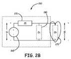
図2Bは、MRIスキャナによって生成されたRF電磁エネルギーから、リード150上で取得されたRFエネルギーを表す、図2Aのリード150に対する簡単化した等価回路260を示す概略図である。図2Bで示すように、回路260の電圧(Vi)265は、MRIスキャナからリード150で取得された等価なエネルギー源を表している。磁気共鳴撮像中は、リード150の長さは、アンテナと同様に機能し、MRIスキャナから体に送られたRFエネルギーを受け取る。図2Bの電圧(Vi)265は、例えば、RFエ
ネルギーからリード150を介して受信され得られた電圧を表すことができる。リード150を介して取得されたRFエネルギーは、例えば、MRIスキャナによって生成された回転するRF磁場から得ることができ、それは、導電性の組織において、回転する磁場ベクトルに対して直角な平面に電場を生成する。リード150の長さに沿ったこれらの電場の接線方向成分は、リード150に結合される。電圧(Vi)265は、したがって、リード150の長さに沿って、接線方向の電場の積分(すなわち、電場の線積分)に等しい。FIG. 2B is a schematic diagram illustrating a simplified
回路260におけるZIパラメータ270は、MRIスキャナのRF周波数においてリード150によって示される等価なインピーダンスを表す。インピーダンス値ZI270は、例えば、1.5テスラのMRIスキャナに対する64MHzのRF周波数で、または3テスラのMRIスキャナに対する128MHzのRF周波数で、リード150によって示される並列インダクタンス、および巻線キャパシタンス当たりのコイル巻数から得られるインダクタンスまたは等価なインピーダンスを表すことができる。リード150のインピーダンスZIは、実数部(すなわち、抵抗)および虚数部(すなわち、リアクタンス)を有する複素量である。
回路260におけるZb275は、リードの接触点における体組織のインピーダンスを表すことができる。Zc280は、次いで、リード150の長さに沿った周囲の体組織へのリード150の容量結合を表すことができ、それは、高周波電流(エネルギー)が、MRIスキャナのRF周波数で周囲の組織へと洩れるようにするための経路を提供することができる。吸収されるエネルギー(ソースVi265で表される)を最小化することは、体組織とのリードの接触点において、体組織へ移送されるエネルギーを低減する。 Zb275 in
図2Bでさらに分かるように、リード150は、MRIスキャナのRF周波数において周囲の組織中への何らかの洩れ量を有する。さらに275で示されるように、心臓160内の周囲の体組織へのリード電極255、257の接触点においてもインピーダンスがある。結果として体組織に加えられる電圧Vbは、以下の式で関係付けられる。 As can be further seen in FIG. 2B, the
Vb=Vi Zbe/(Zbe+ZI)、ただし、Zbe=Zbであり、Zcと並列である。
周囲組織に対して通常接触が行われるリード150の先端部の温度は、275で(すなわち、「Zb」で)放散される電力に部分的に関連しており、それは、次いで、Vbの2乗に関係する。275で放散された電力から生ずる温度上昇を最小化するためには、したがって、リード150のインピーダンスZI(270)も最大化しながら、Vi(265)およびZc(280)を最小化することが望ましい。或る実施形態では、リード150のインピーダンスZI(270)は、MRIスキャナのRF周波数で増加させることができ、それが、接触点275における周囲の体組織へと放散されるエネルギーを低減することを助ける。Vb = Vi Zbe / (Zbe + ZI), where Zbe = Zb and parallel to Zc.
The temperature at the tip of the
以下でさらに詳細に述べる様々な実施形態では、リード150のインピーダンスは、リード150にインダクタンスを加えることによって、かつ/または適切な構成技法によって増加されうる。例えば、様々な実施形態では、リード150のインダクタンスは、電気エネルギーを電極255、257に供給するために使用される導体を選択的に構成することによって増加する。 In various embodiments described in further detail below, the impedance of the
図3は、本発明の1または複数の実施形態に従って使用できる例示的なリード150をさらに詳細に示している。図3で示すように、リード本体200は近位端305を含み、またリード150は、リード本体の近位端305に結合されたコネクタ組立体310、コイル電極255、257、およびペーシング/感知電極として例示的な実施形態で動作す
る先端電極312をさらに含む。PG140(図1を参照のこと)の機能的な要件、および患者の治療の必要性に応じて、リード150の遠位領域250は、さらなる電極を含むことができる。例えば、或る実施形態では、1対のコイル電極255、257を、心臓160に除細動ショックを与えるためのショック電極として機能するように使用することができる。或る実施形態では、リード150は、ペーシング/感知電極としても動作可能であり、かつ先端電極312に加えて、またはそれに代えて含むことのできる、リード150の遠位先端に対して近位にある低電圧(例えば、リング)電極を含むことができる。簡単に言うと、リード150は、本発明の実施形態の範囲に含まれる任意の数の電極構成を組み込むことができる。FIG. 3 illustrates in greater detail an
例示の実施形態では、コネクタ組立体310は、コネクタ本体320および端子ピン325を含む。コネクタ組立体310は、リード本体200に結合され、かつリードをPG140(図1および図2を参照のこと)上のヘッダに機械的かつ電気的に結合するように構成されうる。様々な実施形態では、端子ピン325は、コネクタ本体320から近位方向に延びており、また或る実施形態では、リード本体200を介して、先端電極312へと長手方向に延びる内側導体(図3に示されていない)に結合される。或る実施形態では、端子ピン325は、ガイドワイヤまたは挿入スタイレットを収容するための、内側導体コイルによって画定される管腔とそれを通って連通して延びる開口部を含むことができる。 In the illustrated embodiment, the
様々な実施形態では、先端電極312は、リード150の遠位端における電気的にアクティブな固定らせん体(helix)の形をしている。或る実施形態では、先端電極312は、らせん体が回転するとリード本体に対してらせん体の長手方向移動を容易にする機構によって支持される延長可能/後退可能ならせん体とすることができる。これらの実施形態では、端子ピン325は、コネクタ本体320およびリード本体200に対して回転可能にすることができ、したがって、リード本体200に対する端子ピン325の回転は、内側導体を、次いで、らせん体先端電極をリード本体200に対して回転させ、かつ長手方向に移動させる。延長可能/後退可能な固定らせん体組立体(電気的にアクティブとパッシブの両方で)を提供するための様々な機構および技法は、当業者には知られており、ここでさらに詳細に述べる必要はない。 In various embodiments, the
ペーシング/感知電極(上記で述べた堅い先端電極であれ、図3で示すようなアクティブな固定らせん体であれ)は、エルジロイ、MP35N、タングステン、タンタル、イリジウム、プラチナ、チタン、パラジウム、ステンレス鋼、ならびに任意のこれらの材料の合金など、任意の適切な導電性材料から作ることができる。 The pacing / sensing electrode (whether the rigid tip electrode mentioned above or the active fixed helix as shown in FIG. 3) can be selected from Elgiloy, MP35N, tungsten, tantalum, iridium, platinum, titanium, palladium, stainless steel, As well as any suitable conductive material, such as an alloy of any of these materials.
コイル電極255、257は、除細動治療のために、心臓に比較的高電圧の治療ショックを与えるのに適した任意の構成をとることができる。様々な実施形態では、コイル電極255、257は、前の段落で論じたような、任意の適切な導電性材料から作ることができる。リード150はまた、コイル電極255、257をコネクタ組立体310上の電気的な接点に電気的に接続するリード本体200内の導体(図3に示されていない)を含み、それは、次いで、コイル電極255、257をPG140内の電気的コンポーネントに電気的に結合するように構成される。 The
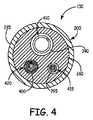
図4では、図3の線4−4に沿ったリード150の横断面図が示されている。図4で示すように、リード本体200は、内側の管状部材380と、内側の管状部材380上に配置され、かつ接着された外側の管状部材385とを含む。管状部材380、385は、シリコーンおよびポリウレタンなどのポリマーおよびそのコポリマーを限定することなく含む、任意の数の絶縁性材料から作られうる。絶縁性材料は、可撓性があり、生体適合性である。さらに示されるように、内側の管状部材380は、複数の管腔390、395、4
00を含み、また導体410、415、および420は、管腔390、395、および400内にそれぞれ配置される。導体410、415、および420のそれぞれは、各管腔390、395、400内で長手方向に延び、かつ電極(例えば、図3の電極312、255、または257)に、さらにコネクタ組立体310の電気的な接点に電気的に結合される。4, a cross-sectional view of the
00, and
或る実施形態では、リード本体200は、別々の同軸の管状部材を含まないが、それに代えて、必要な導体を収容するための1または複数の長手方向管腔を含む単一の管状部材(例えば、部材380)だけを含む。例示のために、内側の管状部材380の3つの管腔390、395、400は、異なる直径を有する状態で示されている。しかし、他の実施形態では、管腔390、395、400の相対的な寸法および/または位置は、図示のものとは変わってもよい。さらに、内側の管状部材380は、リード150の特定の構成に応じて、より多くの、または少ない管腔を含むことができる。例えば、内側の管状部材380は、他のショックコイルおよび/またはペーシング/感知電極に電流を供給するために、リード150内にさらなる導体ワイヤおよび/または電極コイルを収容する多数の管腔を含むことができる。 In some embodiments, the
例示の実施形態では、導体410は、従来の低電圧ペーシング/感知電極、例えば、先端電極312などと共に使用されるような、単層のコイル導体である。或る実施形態では、例えば、コイル導体410は、MRI走査中に存在するような、電磁エネルギーに曝されたとき、比較的高いインピーダンスを有するように構成される。様々なこのような実施形態では、コイル導体410は、例えば、本願明細書にその全体を援用する米国特許出願公開第2009/0198314号で述べられた様々な実施形態に従って構成される。高められたインピーダンスは、リード電極(複数可)で、もしくはその近傍で周囲の体組織中に放散されるエネルギーを低下させるのを助ける。様々な実施形態では、導体410および管腔390は、除外される。 In the illustrated embodiment,
以下でさらに詳細に説明するように、導体415および420は、条件付きで安全なMRIと適合性のあるリード設計を提供するために、ならびに施療中、および長い間続く動作状態下で改良された耐疲労性、および他の機械的特性を提供するために、リード150中に組み込まれる多層の導体組立体である。様々な実施形態では、多層のコイル導体415、420は、刺激/感知リードの本体用として適切な機械的特性を有する、高誘導性であり、高導電性の小径導体を作るように選択的に制御されたコイル特性(例えば、ピッチ、外径、電線太さなど)を有する複数のコイル層を含む。 As described in more detail below,
例示的な実施形態では、コイル導体415は、3層の導体であり、またコイル導体420は、2層の導体である。様々な実施形態では、3を超えるコイル層を使用する多層のコイル導体を使用することができる。様々な実施形態では、単層のコイル導体410は、コイル導体415および/または420と同様の、または同一の多層のコイル導体で置き換えられうる。 In the exemplary embodiment,
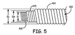
図5は、本発明の1実施形態によるコイル導体420のより詳細な側面図である。図5で示すように、多層のコイル導体420は、外側コイル層422、中間コイル層425、および内側コイル層430を含む3層のコイル導体420である。外側コイル層422は、内側コイル層430の周りに配置された中間コイル層425の周りに配置される。外側、中間、および内側コイル層422、425、430は、コネクタ組立体310と電極255の間で並列な導電性経路を提供するように、少なくともその近位端で(すなわち、コネクタ組立体で、もしくはその近傍で)、ならびにその遠位端で(すなわち、電極255で)互いに並列に、電気的に結合される。様々な実施形態では、コイル層422、425、および430のパラメータは、MRI走査と関連する周波数によって特徴付けられた外
部の交番磁場に曝されたとき、多層のコイル導体420が、約3.0〜3.5オームの最大DC抵抗、および高インピーダンスを有するように構成される。2層のコイル導体415は、図5で示されたコイル導体420と実質的に同様の方法で構成することができ、2つのコイル導体層を含むだけであることが理解されよう。FIG. 5 is a more detailed side view of a
或る実施形態では、コイル導体420の外側層422は、約0.03302センチメートル(0.013インチ)未満のコイル径D0に巻回されうる。或る実施形態では、外側層は、近接させたピッチであり、最大で約0.01016センチメートル(0.004インチ)の電線太さを有する1または複数の電線を有することができる。様々な実施形態によれば、外側層は、リードの所望の用途に応じて存在することも、存在しないこともありうる。例えば、或る場合では、外側層は、多層のコイル導体420の抵抗を変えるために使用されうる。少なくとも1実施形態では、外側層422は、約0.00254センチメートル(0.001インチ)から約0.01016センチメートル(0.004インチ)の電線太さを有することができる。In certain embodiments, the
コイル導体420の中間層425は、近接させたピッチであり、外側コイル層422の内径未満のコイル直径Dmに巻回されうる。或る実施形態では、中間層は、最大で約0.00178センチメートル(0.0007インチ)から約0.00762センチメートル(0.003インチ)の電線太さを有する1または複数の電線を有することができる。
コイル導体420の内側コイル層430は、近接させたピッチであり、中間層425の内径未満のコイル直径Diに巻回されうる。或る実施形態では、内側層は、最大で約0.00178センチメートル(0.0007インチ)から約0.00254センチメートル(0.001インチ)の電線太さを有する1または複数の電線を有することができる。
様々な他の実施形態では、多層のコイル導体420は、リード150に対する動作上の必要性に応じて、各コイル層422、425、430の様々な範囲の寸法、および他のパラメータ(例えば、電線数)を使用する。 In various other embodiments, the
様々な実施形態では、電線の材料は、望ましい電気的かつ機械的特性を示す任意の適切な材料とすることができる。1実施形態では、外側、中間、および/または内側コイル層422、425、430の電線は、MP35Nまたはタンタルで被覆した銀のコア(約40%)を含む引抜き充填管(DFT(登録商標))ワイヤから製作される。他の実施形態では、外側、中間、および/または内側コイル層422、425、430は、MP35Nで被覆したタンタルコアを含むDFTワイヤから製作される。コイル層422、425、430は、同じまたは異なる材料から構成することができ、各コイル層422、425、430は、異なる銀の充填レベルを含むことができる。 In various embodiments, the material of the wire can be any suitable material that exhibits desirable electrical and mechanical properties. In one embodiment, the outer, middle, and / or inner coil layers 422, 425, 430 wires are drawn filled tubes (DFT®) that include a silver core (about 40%) coated with MP35N or tantalum. Made from wire. In other embodiments, the outer, middle, and / or inner coil layers 422, 425, 430 are fabricated from DFT wire that includes a tantalum core coated with MP35N. The coil layers 422, 425, 430 can be composed of the same or different materials, and each
様々な実施形態では、コイル導体420の各層の電線は、同じピッチ方向に巻回される。すなわち、各コイル層の個々の電線は、コイルをその長手方向軸に沿って眺めたとき、右巻きピッチ、または左巻きピッチを有するように巻回される。 In various embodiments, the wires in each layer of the
様々な実施形態では、1または複数のコイル層422、425、430は、その長さに沿って可変のコイルピッチを有しており、それは、外部に加えられる電磁放射(すなわち、MRIの胸部走査による)の影響を低減するために、コイル導体420をデチューンする(detune)ように働く。 In various embodiments, one or more coil layers 422, 425, 430 have a variable coil pitch along their length, which is applied to externally applied electromagnetic radiation (ie, MRI chest scans). In order to reduce the influence of the
様々な実施形態では、個々のコイル層422、425、および430は、MRI状況下でリード150の性能をさらに変えるために、例えば、電線の太さ、ピッチ、および/またはコイル層の直径を変更することによって、それぞれが異なるインダクタンスを示すよ
うに別々に最適化されうる。In various embodiments, the individual coil layers 422, 425, and 430 may change, for example, wire thickness, pitch, and / or coil layer diameter to further change the performance of the
本発明の或る実施形態は、1または複数の隣接するコイル層422、425、または430の間で、1または複数の絶縁層を含む。代替的には、またはさらに、様々な実施形態では、個々の電線またはコイル層422、425、および/または430が個々に絶縁される。望ましい場合、任意の適切な絶縁材料を利用することができる。電線に対する、かつ/またはコイル層間の例示的な絶縁材料は、エチレン・テトラフルオロエチレン(ETFE)、ポリテトラフルオロエチレン(PTFE)、延伸ポリテトラフルオロエチレン(ePTFE)、シリコーン、および前述のもののコポリマーを含む。 Certain embodiments of the present invention include one or more insulating layers between one or more adjacent coil layers 422, 425, or 430. Alternatively or additionally, in various embodiments, the individual wire or
上記で述べたリード150の様々な実施形態は、外部のMRI電磁場に曝された結果生ずるリード導体中の誘起電流を最小化するので有利である。これは、ショック電流をPGからショック電極に送信するために、撚り合わせたケーブル導体を利用する従来のリードシステムとは対照的である。このようなケーブル導体は、抗頻脈治療を施すための優れた電気的性能を提供するが、撚り合わせたケーブル導体はまた、低いインピーダンスを有しており、したがって、MRI走査中に存在するような、交流電磁場に曝されたとき、誘起される電流の生成の影響を受けやすい。本発明の様々な実施形態によれば、リード150は、MRI放射に曝されたとき、除細動リードにおける高電圧のショックコイルにエネルギーを供給するために従来使用される従来の高エネルギーケーブルを使用して経験する温度上昇のほぼ半分の上昇を示す結果が得られる。上記で述べたリード150に対する高インピーダンスの導体構成は、MRI放射の影響を最小化するが、なお、抗頻脈治療用途で使用するのに適した電気的性能を提供する。 The various embodiments of the
さらに、或る実施形態によれば、多層のコイル導体の設計パラメータは、例えば、有効なばね定数、したがって、リード組立体全体の剛性、曲げ剛性などの機械的な特性を制御するために調整されうる。このような調整によって、ユーザは、隣接する(遠位の)ポリマーコンポーネント上の応力(負荷)を最小化し、剪断接着破壊の可能性を最小化し、リードの形を容易に制御し、かつ低電圧および高電圧のリード用途の両方で、組立中の軸方向長さの許容差が積算(stack−up)されることの影響を最小限にすることを可能にする。例えば、様々な実施形態では、ショックコイル255、257(図2Aおよび3を参照のこと)が除外され、またリード150は、先端電極312、およびリード150に沿ってさらなるリング電極など、1または複数の低電圧ペーシング/感知電極だけを含む。このような実施形態では、コイル導体425および/または420などの多層のコイル導体を使用して、薄型の設計で十分な電気的性能を提供し、さらにリード本体200など、隣接する絶縁性コンポーネントに対して、軸方向剛性などの最適な機械的特性も提供することができる。 Further, according to some embodiments, the design parameters of the multi-layer coil conductor are adjusted to control, for example, effective spring constants and thus mechanical properties such as overall lead assembly stiffness, bending stiffness, etc. sell. Such adjustment allows the user to minimize stress (load) on adjacent (distal) polymer components, minimize the possibility of shear bond failure, easily control the shape of the leads, and reduce the voltage In both high voltage lead applications, it is possible to minimize the effects of stack-up axial length tolerance during assembly. For example, in various embodiments,
様々な実施形態では、多層のコイル導体415および/または420は、導体コイルと、隣接する絶縁要素(すなわち、リード本体200のコンポーネント)との間の軸方向剛性の差を低減するまたはなくすために、コイル導体415および/または420の有効なばね定数(単位長さ当たりの力で表される)を制御するように調整されうる。このように、コイル導体のばね定数/軸方向剛性を制御し、かつ最適化することによって、例えば、コイル導体415、420が、リード本体コンポーネントの近位で終了する場合に、ポリマーのリード本体コンポーネントの全体の軸方向強度を維持することができる。さらに、導体と、平行なポリマーのリード本体コンポーネントとの軸方向剛性の大きな差を(すなわち、多層のコイル導体415および/または420を利用することによって)低減するまたはなくすことによって、これらの要素間の剪断力が低減されるので有利である。導体ケーブルに代えて多層のコイル導体415、420を利用することはまた、導体の蛇行をなくす。導体の蛇行は、導体に対する引張り軸方向負荷の縮小および解放により生ずるおそれがある。 In various embodiments,
上記で論じた機械的特性を調整/最適化するために変わる可能性のある例示的な設計パラメータは、限定することなく、導体材料、層の数、巻きの幾何形状、ピッチ、電線の直径、電線数、および他のものを選択することを含むことができる。 Exemplary design parameters that may change to tune / optimize the mechanical properties discussed above include, but are not limited to, conductor material, number of layers, winding geometry, pitch, wire diameter, It may include selecting the number of wires, and others.
上記で述べたコイル導体の構成に加えて、本発明のリード150の様々な実施形態は、任意選択で、他の特徴または技法を組み込んで、MRI放射の影響を最小化することができる。例えば、或る実施形態では、リード150から取得される電磁エネルギー量をさらに低減するように、シールドをリード150に追加することができる。例えば、シールドから得られるエネルギーは、リード150の長さに沿った患者の体に結合することができ、エネルギーがリード先端に結合されることを阻止する。シールド/リードの長さに沿った且つシールドによって遮られたエネルギーが移送されることを、シールド構成に対して抵抗性材料を使用し、且つ抵抗損失としてエネルギーを放散させることによって抑制することもできる。 In addition to the coil conductor configurations described above, various embodiments of the
様々な変更および追加を、本発明の範囲から逸脱することなく、前に論議した例示的な実施形態に行うことができる。例えば、上記で述べた諸実施形態は、特定の特徴について述べているが、本発明の範囲はまた、前述の特徴のすべてを含んでいない、特徴および実施形態の様々な組合せを有する実施形態も含む。したがって、本発明の範囲は、すべてのこのような代替形態、変更形態、および変形形態を、特許請求の範囲に含まれるものとして、そのすべての均等な形態と共に包含することが意図される。 Various changes and additions can be made to the exemplary embodiments discussed above without departing from the scope of the invention. For example, although the embodiments described above describe specific features, the scope of the invention also includes embodiments having various combinations of features and embodiments that do not include all of the features described above. Including. Accordingly, the scope of the invention is intended to embrace all such alternatives, modifications, and variations as if they fall within the scope of the claims, along with all their equivalent forms.
Claims (19)
Translated fromJapanese近位端を含む近位領域と、遠位領域と、前記近位端から前記遠位領域を通って延びる長手方向の本体管腔とを有する可撓性の本体と;
植込み可能な電気的リードを、植込み可能なパルス発生器に機械的かつ電気的に接続するように構成されたコネクタ組立体と;
前記遠位領域で前記可撓性の本体に結合される電極と;
前記コネクタ組立体から少なくとも前記電極へと前記長手方向の本体管腔内で延びる多層のコイル導体と
を備え、
前記多層のコイル導体は、
近接したピッチを有するように巻回された1または複数の電線である第1電線を含む第1のコイル層と;
前記第1のコイル層の周囲に配置された第2のコイル層であって、前記第2のコイル層は、近接したピッチを有するように巻回された1または複数のワイヤである第2電線を含み、前記第2電線は、前記第1電線と同じピッチ方向に巻回される、第2のコイル層と
を含み、
前記第1のコイル層および前記第2のコイル層は、互いに電気的に結合され、
前記第1のコイル層および前記第2のコイル層は、前記コネクタ組立体と前記電極の間で並列な導電性の経路を提供することによって、前記多層のコイル導体が最大で約3から3.5オームのDC抵抗を有するように構成される、植込み可能な電気的リード。Implantable electrical leads,
A flexible body having a proximal region including a proximal end, a distal region, and a longitudinal body lumen extending from the proximal end through the distal region;
A connector assembly configured to mechanically and electrically connect the implantable electrical lead to the implantable pulse generator;
An electrode coupled to the flexible body at the distal region;
A multilayer coil conductor extending from the connector assembly to at least the electrode in the longitudinal body lumen;
The multilayer coil conductor is:
A first coil layer including a first wire that is one or more wires wound to have a close pitch;
A second coil layer disposed around the first coil layer, wherein the second coil layer is one or a plurality of wires wound to have a close pitch. And the second electric wire includes a second coil layer wound in the same pitch direction as the first electric wire,
The first coil layer and the second coil layer are electrically coupled to each other;
The first coil layer and the second coil layer provide parallel conductive paths between the connector assembly and the electrodes, so that the multilayer coil conductors are at most about 3-3. Implantable electrical lead configured to have a DC resistance of 5 ohms.
請求項1記載の植込み可能な電気的リード。The first electric wire and the second electric wire are individually electrically insulated,
The implantable electrical lead of claim 1.
1または複数の前記第2電線は、互いに電気的に絶縁されておらず、
前記リードはさらに、前記第1のコイル層と前記第2のコイル層の間に少なくとも部分的に配置された絶縁材料の層を含む、
請求項1記載の植込み可能な電気的リード。The one or more first electric wires are not electrically insulated from each other;
The one or more second electric wires are not electrically insulated from each other;
The lead further includes a layer of insulating material disposed at least partially between the first coil layer and the second coil layer.
The implantable electrical lead of claim 1.
請求項1記載の植込み可能な電気的リード。The one or more of the first wires and the one or more of the second wires are made from a draw-filled tube (DFT®) wire that includes a silver core and an outer coating of a cobalt-nickel-molybdenum alloy.
The implantable electrical lead of claim 1.
前記第2電線は、最大で約0.00762センチメートル(0.003インチ)の電線太さを有する、
請求項1記載の植込み可能な電気的リード。The first wire has a wire thickness of at most about 0.00254 centimeters (0.001 inch);
The second wire has a wire thickness of at most about 0.00762 centimeters (0.003 inches);
The implantable electrical lead of claim 1.
前記第3のコイル層は、近接したピッチで、かつ前記第1電線および前記第2電線と同じピッチ方向に巻回された1または複数の電線である第3電線を含む、
請求項1記載の植込み可能な電気的リード。The implantable electrical lead further comprises a third coil layer disposed around the second coil layer;
The third coil layer includes a third electric wire that is one or a plurality of electric wires wound at a close pitch and in the same pitch direction as the first electric wire and the second electric wire,
The implantable electrical lead of claim 1.
請求項6記載の植込み可能な電気的リード。The third coil layer has a wire thickness of at most about 0.01016 centimeters;
The implantable electrical lead of claim 6.
請求項7記載の植込み可能な電気的リード。The inductances of the first coil layer, the second coil layer, and the third coil layer are different from each other.
The implantable electrical lead of claim 7.
請求項1記載の植込み可能な電気的リード。The first coil layer and the second coil layer have a configuration of one electric wire, two electric wires, three electric wires, or four electric wires,
The implantable electrical lead of claim 1.
請求項1記載の植込み可能な電気的リード。The first coil layer, including both ends, has a wire thickness between 0.00254 centimeters (0.001 inches) and 0.00508 centimeters (0.002 inches);
The implantable electrical lead of claim 1.
前記第1のコイル層の外径は、0.01016センチメートル(0.004インチ)未満である、
請求項1記載の植込み可能な電気的リード。The first coil layer is formed from 0.00178 centimeter (0.0007 inch) draw-filled tube (DFT®) wire with 1 to 4 wire configurations;
The outer diameter of the first coil layer is less than 0.004 inches;
The implantable electrical lead of claim 1.
請求項11記載の植込み可能な電気的リード。The second coil layer, including both ends, has a wire thickness between 0.00178 centimeters (0.0007 inches) and 0.00762 centimeters (0.003 inches).
The implantable electrical lead of claim 11.
近位端を含む近位領域と、遠位領域と、前記近位端から前記遠位領域を通って延びる長手方向の本体管腔とを有する可撓性の本体と;
植込み可能な医療用リードを、植込み可能なパルス発生器に機械的かつ電気的に接続するように構成されたコネクタ組立体と;
前記遠位領域で前記可撓性の本体に結合される電極と;
前記コネクタ組立体から少なくとも前記電極へと前記長手方向の本体管腔内で延びる多層のコイル導体と
を備え、前記多層のコイル導体は、
外径(OD)と、近接したピッチと、時計方向または反時計方向の内側コイルピッチ方向とを有する内側コイル導体と;
近接したピッチと、前記内側コイルピッチ方向と同じ中間コイルピッチ方向と、前記内側コイル導体の前記外径(OD)よりも大きい内径(ID)とを有する中間コイル導体であって、前記中間コイル導体は、前記内側コイル導体の長さに沿って前記内側コイル導体を半径方向に囲む、中間コイル導体と;
前記中間コイル導体を半径方向に囲む外側コイル導体であって、前記外側コイル導体は、近接したピッチと、前記内側コイルピッチ方向と同じ外側コイルピッチ方向とを有する、外側コイル導体と
を含み、
前記内側コイル導体と、前記中間コイル導体と、前記外側コイル導体は、電気的に並列に結合され、約3.5オームのDC抵抗が得られる、植込み可能な医療用リード。An implantable medical lead,
A flexible body having a proximal region including a proximal end, a distal region, and a longitudinal body lumen extending from the proximal end through the distal region;
A connector assembly configured to mechanically and electrically connect an implantable medical lead to an implantable pulse generator;
An electrode coupled to the flexible body at the distal region;
A multilayer coil conductor extending within the longitudinal body lumen from the connector assembly to at least the electrode, the multilayer coil conductor comprising:
An inner coil conductor having an outer diameter (OD), a close pitch, and a clockwise or counterclockwise inner coil pitch direction;
An intermediate coil conductor having a close pitch, an intermediate coil pitch direction that is the same as the inner coil pitch direction, and an inner diameter (ID) that is greater than the outer diameter (OD) of the inner coil conductor, the intermediate coil conductor An intermediate coil conductor that radially surrounds the inner coil conductor along a length of the inner coil conductor;
An outer coil conductor radially surrounding the intermediate coil conductor, the outer coil conductor including an outer coil conductor having a close pitch and the same outer coil pitch direction as the inner coil pitch direction;
The implantable medical lead, wherein the inner coil conductor, the intermediate coil conductor, and the outer coil conductor are electrically coupled in parallel to provide a DC resistance of about 3.5 ohms.
請求項13記載の植込み可能な医療用リード。The medical lead further includes one or more layers of insulating material surrounding one or more of the inner coil conductor, the intermediate coil conductor, or the outer coil conductor.
14. The implantable medical lead according to claim 13.
請求項13記載の植込み可能な医療用リード。The inner coil conductor, the intermediate coil conductor, or the outer coil conductor has a configuration of 1 to 4 electric wires, and each has a different pitch.
14. The implantable medical lead according to claim 13.
請求項13記載の植込み可能な医療用リード。The inner coil conductor has a wire thickness of 0.00254 centimeters (0.001 inches) or less;
14. The implantable medical lead according to claim 13.
請求項16記載の植込み可能な医療用リード。The inner coil conductor has a 0.00178 centimeter (0.0007 inch) draw with an assembly of 1-4 wires and an outer diameter (OD) less than 0.01016 centimeters (0.004 inch). Formed from a filled tube (DFT®) wire,
The implantable medical lead of claim 16.
請求項17記載の植込み可能な医療用リード。The outer coil conductor, including both ends, has a wire diameter between 0.00178 centimeters (0.0007 inches) and 0.00762 centimeters (0.003 inches).
18. The implantable medical lead according to claim 17.
請求項13記載の植込み可能な医療用リード。Each of the wires of the inner coilconductor layer, the intermediate coilconductor layer, and the outer coilconductor layer are individually insulated.
14. The implantable medical lead according to claim 13.
Applications Claiming Priority (3)
| Application Number | Priority Date | Filing Date | Title |
|---|---|---|---|
| US29155709P | 2009-12-31 | 2009-12-31 | |
| US61/291,557 | 2009-12-31 | ||
| PCT/US2010/055653WO2011081713A1 (en) | 2009-12-31 | 2010-11-05 | Mri conditionally safe lead with multi-layer conductor |
Publications (2)
| Publication Number | Publication Date |
|---|---|
| JP2013516223A JP2013516223A (en) | 2013-05-13 |
| JP5542217B2true JP5542217B2 (en) | 2014-07-09 |
Family
ID=43432139
Family Applications (1)
| Application Number | Title | Priority Date | Filing Date |
|---|---|---|---|
| JP2012547075AExpired - Fee RelatedJP5542217B2 (en) | 2009-12-31 | 2010-11-05 | MRI conditional and safe lead with multilayer conductor |
Country Status (6)
| Country | Link |
|---|---|
| US (2) | US8798767B2 (en) |
| EP (1) | EP2519305B1 (en) |
| JP (1) | JP5542217B2 (en) |
| CN (1) | CN102655908B (en) |
| AU (1) | AU2010337313B2 (en) |
| WO (1) | WO2011081713A1 (en) |
Families Citing this family (44)
| Publication number | Priority date | Publication date | Assignee | Title |
|---|---|---|---|---|
| US7610101B2 (en) | 2006-11-30 | 2009-10-27 | Cardiac Pacemakers, Inc. | RF rejecting lead |
| AU2008335462B2 (en) | 2007-12-06 | 2014-02-20 | Cardiac Pacemakers, Inc. | Implantable lead having a variable coil conductor pitch |
| WO2009100003A1 (en) | 2008-02-06 | 2009-08-13 | Cardiac Pacemakers, Inc. | Lead with mri compatible design features |
| US8103360B2 (en) | 2008-05-09 | 2012-01-24 | Foster Arthur J | Medical lead coil conductor with spacer element |
| US9084883B2 (en) | 2009-03-12 | 2015-07-21 | Cardiac Pacemakers, Inc. | Thin profile conductor assembly for medical device leads |
| ES2547713T3 (en) | 2009-06-26 | 2015-10-08 | Cardiac Pacemakers, Inc. | Bypass of a medical device that includes a single-coil coil with improved torque transmission capacity and reduced RM heating |
| US8825158B2 (en) | 2009-08-25 | 2014-09-02 | Lamda Nu, Llc | Method and apparatus for detection of lead conductor anomalies using dynamic electrical parameters |
| US9254380B2 (en) | 2009-10-19 | 2016-02-09 | Cardiac Pacemakers, Inc. | MRI compatible tachycardia lead |
| US9750944B2 (en) | 2009-12-30 | 2017-09-05 | Cardiac Pacemakers, Inc. | MRI-conditionally safe medical device lead |
| WO2011081713A1 (en) | 2009-12-31 | 2011-07-07 | Cardiac Pacemakers, Inc. | Mri conditionally safe lead with multi-layer conductor |
| US8391994B2 (en) | 2009-12-31 | 2013-03-05 | Cardiac Pacemakers, Inc. | MRI conditionally safe lead with low-profile multi-layer conductor for longitudinal expansion |
| US8825181B2 (en) | 2010-08-30 | 2014-09-02 | Cardiac Pacemakers, Inc. | Lead conductor with pitch and torque control for MRI conditionally safe use |
| EP2476455A1 (en)* | 2011-01-13 | 2012-07-18 | BIOTRONIK SE & Co. KG | Implantable electrode lead |
| CN103083808B (en)* | 2011-10-28 | 2016-04-27 | 清华大学 | Pacing lead and pacemaker |
| CN103083806B (en) | 2011-10-28 | 2016-06-08 | 清华大学 | Pacing lead and pacemaker |
| CN103093865B (en) | 2011-10-28 | 2015-06-03 | 清华大学 | Pacemaker electrode line and pacemaker |
| CN103083807B (en)* | 2011-10-28 | 2016-04-27 | 清华大学 | The preparation method of pacing lead |
| CN103093858B (en) | 2011-10-28 | 2016-10-19 | 清华大学 | Pacemaker lead and pacemaker |
| CN103093859B (en) | 2011-10-28 | 2015-08-26 | 清华大学 | Pacing lead and pacemaker |
| US8666512B2 (en) | 2011-11-04 | 2014-03-04 | Cardiac Pacemakers, Inc. | Implantable medical device lead including inner coil reverse-wound relative to shocking coil |
| CN103957979B (en)* | 2011-11-29 | 2017-09-12 | 皇家飞利浦有限公司 | For the pipe being introduced into subject |
| AU2013249088B2 (en)* | 2012-04-20 | 2015-12-03 | Cardiac Pacemakers, Inc. | Implantable medical device lead including a unifilar coiled cable |
| US9272150B2 (en) | 2012-06-01 | 2016-03-01 | Lambda Nu Technology Llc | Method for detecting and localizing insulation failures of implantable device leads |
| US8954168B2 (en) | 2012-06-01 | 2015-02-10 | Cardiac Pacemakers, Inc. | Implantable device lead including a distal electrode assembly with a coiled component |
| US8812103B2 (en) | 2012-06-01 | 2014-08-19 | Lamda Nu, Llc | Method for detecting and treating insulation lead-to-housing failures |
| JP6069499B2 (en) | 2012-08-31 | 2017-02-01 | カーディアック ペースメイカーズ, インコーポレイテッド | Lead wire with low peak MRI heating |
| US8983623B2 (en) | 2012-10-18 | 2015-03-17 | Cardiac Pacemakers, Inc. | Inductive element for providing MRI compatibility in an implantable medical device lead |
| WO2014074876A1 (en)* | 2012-11-09 | 2014-05-15 | Cardiac Pacemakers, Inc. | Implantable lead having a lumen with a wear-resistant liner |
| US9675799B2 (en) | 2012-12-05 | 2017-06-13 | Lambda Nu Technology Llc | Method and apparatus for implantable cardiac lead integrity analysis |
| US10840005B2 (en) | 2013-01-25 | 2020-11-17 | Vishay Dale Electronics, Llc | Low profile high current composite transformer |
| US10039919B2 (en) | 2013-04-30 | 2018-08-07 | Lambda Nu Technology Llc | Methods and apparatus for detecting and localizing partial conductor failures of implantable device leads |
| US9486624B2 (en) | 2013-06-13 | 2016-11-08 | Lambda Nu Technology Llc | Detection of implantable lead failures by differential EGM analysis |
| US10118031B2 (en) | 2013-06-28 | 2018-11-06 | Lambda Nu Technology Llc | Method and apparatus for implantable cardiac lead integrity analysis |
| WO2015130753A1 (en) | 2014-02-26 | 2015-09-03 | Cardiac Pacemakers, Inc | Construction of an mri-safe tachycardia lead |
| US9636500B2 (en) | 2014-03-25 | 2017-05-02 | Lambda Nu Technology Llc | Active surveillance of implanted medical leads for lead integrity |
| US11511085B2 (en) | 2015-11-18 | 2022-11-29 | Heraeus Deutschland GmbH & Co. KG | Torque coil and method |
| US10252069B1 (en) | 2015-11-19 | 2019-04-09 | Lambda Nu Technology Llc | Micro-charge ICD lead testing method and apparatus |
| EP3442651B1 (en)* | 2016-04-15 | 2022-04-13 | Medtronic, Inc. | Medical device lead assembly with variable pitch coil |
| US11666251B2 (en) | 2016-10-31 | 2023-06-06 | Heraeus Deutschland GmbH & Co. KG | Signal and torque transmitting torque coil |
| US11129980B2 (en) | 2017-03-02 | 2021-09-28 | Saluda Medical Pty Limited | Electrode assembly |
| US10543364B2 (en) | 2017-04-07 | 2020-01-28 | Lambda Nu Technology Llc | Detection of lead electrode dislodgement using cavitary electrogram |
| CN110996788B (en)* | 2017-08-07 | 2023-05-16 | 德普伊新特斯产品公司 | Folded MRI safety coil assembly |
| WO2021062480A1 (en) | 2019-10-04 | 2021-04-08 | Saluda Medical Pty Limited | Lead for an active implantable medical device |
| US11672976B2 (en) | 2019-10-10 | 2023-06-13 | Saluda Medical Pty Limited | Lead for an active implantable medical device with decoy |
Family Cites Families (311)
| Publication number | Priority date | Publication date | Assignee | Title |
|---|---|---|---|---|
| US3614692A (en) | 1970-06-02 | 1971-10-19 | Magnetech Ind Inc | Variable induction device |
| US4135518A (en) | 1976-05-21 | 1979-01-23 | Medtronic, Inc. | Body implantable lead and electrode |
| US4131759A (en) | 1977-08-10 | 1978-12-26 | United States Steel Corporation | Slip sleeve mechanism for a strength tapered caged armored electromechanical cable |
| US4146036A (en) | 1977-10-06 | 1979-03-27 | Medtronic, Inc. | Body-implantable lead with protector for tissue securing means |
| US4350169A (en) | 1979-01-05 | 1982-09-21 | Medtronic, Inc. | Flexible tip stiffening stylet for use with body implantable lead |
| US4209019A (en) | 1979-01-05 | 1980-06-24 | Medtronic, Inc. | Stylet insertion guide and rotation control device for use with body implantable lead |
| US4253462A (en) | 1979-08-09 | 1981-03-03 | Medtronic, Inc. | Stylet |
| US4381013A (en) | 1981-03-19 | 1983-04-26 | Medtronic, Inc. | "J" Stylet wire |
| US4404125A (en) | 1981-10-14 | 1983-09-13 | General Electric Company | Polyphenylene ether resin compositions for EMI electromagnetic interference shielding |
| US4484586A (en) | 1982-05-27 | 1984-11-27 | Berkley & Company, Inc. | Hollow conductive medical tubing |
| GB2126466B (en) | 1982-07-01 | 1986-03-12 | Molins Plc | Conveying and uniting rod-like articles of the tobacco industry |
| US4437474A (en) | 1982-07-16 | 1984-03-20 | Cordis Corporation | Method for making multiconductor coil and the coil made thereby |
| US4493329A (en) | 1982-08-19 | 1985-01-15 | Lynn Crawford | Implantable electrode having different stiffening and curvature maintaining characteristics along its length |
| US4574800A (en) | 1984-12-07 | 1986-03-11 | Cordis Corporation | Implanted lead extractor |
| US4643202A (en) | 1985-04-15 | 1987-02-17 | Cordis Corporation | Multi-material insulation sheath for pacer lead |
| US4649938A (en) | 1985-04-29 | 1987-03-17 | Mcarthur William A | Tissue-stimulating electrode having sealed, low-friction extendable/retractable active fixation means |
| US4869970A (en) | 1986-07-14 | 1989-09-26 | Shipley Company Inc. | Radiation attenuation shielding |
| US5003975A (en) | 1988-04-19 | 1991-04-02 | Siemens-Pacesetter, Inc. | Automatic electrode configuration of an implantable pacemaker |
| US5074313A (en) | 1989-03-20 | 1991-12-24 | Cardiac Pacemakers, Inc. | Porous electrode with enhanced reactive surface |
| US5002067A (en) | 1989-08-23 | 1991-03-26 | Medtronic, Inc. | Medical electrical lead employing improved penetrating electrode |
| US5056516A (en) | 1989-11-02 | 1991-10-15 | Intermedics, Inc. | Implantable endocordial lead with torque-transmitting lanyard |
| US5269319A (en) | 1989-12-08 | 1993-12-14 | Cardiac Pacemakers, Inc. | Unitary intravascular defibrillating catheter with bipolar sensing |
| US5020545A (en) | 1990-01-23 | 1991-06-04 | Siemens-Pacesetter, Inc. | Cardiac lead assembly and method of attaching a cardiac lead assembly |
| US5243911A (en) | 1990-09-18 | 1993-09-14 | Dow Robert L | Attenuator for protecting electronic equipment from undesired exposure to RF energy and/or lightning |
| US5144960A (en) | 1991-03-20 | 1992-09-08 | Medtronic, Inc. | Transvenous defibrillation lead and method of use |
| US5217010A (en) | 1991-05-28 | 1993-06-08 | The Johns Hopkins University | Ecg amplifier and cardiac pacemaker for use during magnetic resonance imaging |
| US5222506A (en) | 1991-07-29 | 1993-06-29 | Medtronic, Inc. | Implantable medical lead with electrical cross-over adaptor |
| US5201865A (en) | 1991-10-28 | 1993-04-13 | Medtronic, Inc. | Medical lead impedance measurement system |
| US5246014A (en) | 1991-11-08 | 1993-09-21 | Medtronic, Inc. | Implantable lead system |
| US5241957A (en) | 1991-11-18 | 1993-09-07 | Medtronic, Inc. | Bipolar temporary pacing lead and connector and permanent bipolar nerve wire |
| US5259395A (en) | 1992-01-15 | 1993-11-09 | Siemens Pacesetter, Inc. | Pacemaker lead with extendable retractable lockable fixing helix |
| US5231996A (en) | 1992-01-28 | 1993-08-03 | Medtronic, Inc. | Removable endocardial lead |
| WO1993017074A1 (en) | 1992-02-24 | 1993-09-02 | Baxter International Inc. | Polymer blends for torque transmitting catheters |
| US5324322A (en) | 1992-04-20 | 1994-06-28 | Case Western Reserve University | Thin film implantable electrode and method of manufacture |
| SE9201745D0 (en) | 1992-06-05 | 1992-06-05 | Siemens Elema Ab | PACEMAKER |
| US5649974A (en) | 1992-07-27 | 1997-07-22 | Angeion Corporation | Low profile defibrillation catheter |
| US5447533A (en) | 1992-09-03 | 1995-09-05 | Pacesetter, Inc. | Implantable stimulation lead having an advanceable therapeutic drug delivery system |
| JPH06205842A (en) | 1992-12-04 | 1994-07-26 | Siemens Ag | Lead assembly for implantable medical device |
| US5330522A (en) | 1992-12-29 | 1994-07-19 | Siemens Pacesetter, Inc. | Ring electrode for a multilumen lead and method of constructing a multilumen lead |
| US5300108A (en) | 1993-01-05 | 1994-04-05 | Telectronics Pacing Systems, Inc. | Active fixation lead with a dual-pitch, free spinning compound screw |
| CA2152604C (en) | 1993-02-01 | 2000-05-09 | Thomas M. Soukup | An implantable electrode |
| US5378234A (en) | 1993-03-15 | 1995-01-03 | Pilot Cardiovascular Systems, Inc. | Coil polymer composite |
| US5354327A (en) | 1993-04-07 | 1994-10-11 | Medtronic, Inc. | Conductor coil with specific ratio of torque to bending stiffness |
| US5476485A (en) | 1993-09-21 | 1995-12-19 | Pacesetter, Inc. | Automatic implantable pulse generator |
| US5439485A (en) | 1993-09-24 | 1995-08-08 | Ventritex, Inc. | Flexible defibrillation electrode of improved construction |
| US5417208A (en) | 1993-10-12 | 1995-05-23 | Arrow International Investment Corp. | Electrode-carrying catheter and method of making same |
| CA2174129C (en) | 1993-10-14 | 2004-03-09 | Sidney D. Fleischman | Electrode elements for forming lesion patterns |
| US5456707A (en) | 1993-10-22 | 1995-10-10 | Vitatron Medical Bv | Pacing lead with improved torsion characteristics |
| JPH07178176A (en) | 1993-12-24 | 1995-07-18 | Terumo Corp | Catheter |
| US5483022A (en) | 1994-04-12 | 1996-01-09 | Ventritex, Inc. | Implantable conductor coil formed from cabled composite wire |
| US5618208A (en) | 1994-06-03 | 1997-04-08 | Siemens Medical Systems, Inc. | Fully insulated, fully shielded electrical connector arrangement |
| US5574249A (en) | 1994-07-18 | 1996-11-12 | Lindsay Audiophile Inc. | High resistivity inner shields for cabinets housing electronic circuitry |
| US5522875A (en) | 1994-07-28 | 1996-06-04 | Medtronic, Inc. | Medical electrical lead system having a torque transfer stylet |
| WO1996006655A1 (en) | 1994-08-29 | 1996-03-07 | Angeion Corporation | Low profile defibrillation catheter |
| SE9403279D0 (en)* | 1994-09-29 | 1994-09-29 | Siemens Elema Ab | The electrode device |
| US5534018A (en) | 1994-11-30 | 1996-07-09 | Medtronic, Inc. | Automatic lead recognition for implantable medical device |
| US5549646A (en) | 1994-12-06 | 1996-08-27 | Pacesetter, Inc. | Periodic electrical lead intergrity testing system and method for implantable cardiac stimulating devices |
| US5522872A (en) | 1994-12-07 | 1996-06-04 | Ventritex, Inc. | Electrode-conductor sleeve joint for cardiac lead |
| US5599576A (en) | 1995-02-06 | 1997-02-04 | Surface Solutions Laboratories, Inc. | Medical apparatus with scratch-resistant coating and method of making same |
| DE69606845T2 (en) | 1995-04-28 | 2000-06-15 | Target Therapeutics, Inc. | High performance catheter with braided element |
| US5584873A (en) | 1995-05-08 | 1996-12-17 | Medtronic, Inc. | Medical lead with compression lumens |
| US5728149A (en) | 1995-12-20 | 1998-03-17 | Medtronic, Inc. | Integral spiral band electrode for transvenous defibrillation leads |
| US5727552A (en) | 1996-01-11 | 1998-03-17 | Medtronic, Inc. | Catheter and electrical lead location system |
| US5727553A (en) | 1996-03-25 | 1998-03-17 | Saad; Saad A. | Catheter with integral electromagnetic location identification device |
| US5927345A (en) | 1996-04-30 | 1999-07-27 | Target Therapeutics, Inc. | Super-elastic alloy braid structure |
| US5824026A (en) | 1996-06-12 | 1998-10-20 | The Spectranetics Corporation | Catheter for delivery of electric energy and a process for manufacturing same |
| US5800496A (en) | 1996-06-24 | 1998-09-01 | Medtronic, Inc. | Medical electrical lead having a crush resistant lead body |
| US5810887A (en) | 1996-08-23 | 1998-09-22 | Rhythm Technologies, Inc. | Temporary catheter |
| US5760341A (en) | 1996-09-10 | 1998-06-02 | Medtronic, Inc. | Conductor cable for biomedical lead |
| US5755742A (en) | 1996-11-05 | 1998-05-26 | Medtronic, Inc. | Cardioversion/defibrillation lead impedance measurement system |
| US5968087A (en) | 1996-12-19 | 1999-10-19 | Medtronic, Inc. | Multi-component lead body for medical electrical leads |
| EP0971767A2 (en) | 1996-12-19 | 2000-01-19 | Medtronic, Inc. | Medical electrical lead |
| US5766227A (en) | 1997-03-04 | 1998-06-16 | Nappholz; Tibor A. | EMI detection in an implantable pacemaker and the like |
| US6038472A (en) | 1997-04-29 | 2000-03-14 | Medtronic, Inc. | Implantable defibrillator and lead system |
| US6078840A (en) | 1997-04-30 | 2000-06-20 | Medtronic, Inc. | Medical electrical lead having improved fixation |
| US5817136A (en) | 1997-05-02 | 1998-10-06 | Pacesetter, Inc. | Rate-responsive pacemaker with minute volume determination and EMI protection |
| US6103636A (en) | 1997-08-20 | 2000-08-15 | Micron Technology, Inc. | Method and apparatus for selective removal of material from wafer alignment marks |
| DE19736449A1 (en) | 1997-08-21 | 1999-02-25 | Gfe Met & Mat Gmbh | Composite |
| US6249708B1 (en) | 1997-08-26 | 2001-06-19 | Angeion Corporation | Fluted channel construction for a multi-conductor catheter lead |
| US5891114A (en) | 1997-09-30 | 1999-04-06 | Target Therapeutics, Inc. | Soft-tip high performance braided catheter |
| US5891179A (en) | 1997-11-20 | 1999-04-06 | Paceseter, Inc. | Method and apparatus for monitoring and displaying lead impedance in real-time for an implantable medical device |
| US5849031A (en) | 1997-12-16 | 1998-12-15 | Medtronic, Inc. | Method and apparatus for termination of tachyarrhythmias |
| US6501994B1 (en) | 1997-12-24 | 2002-12-31 | Cardiac Pacemakers, Inc. | High impedance electrode tip |
| US5957970A (en) | 1998-02-18 | 1999-09-28 | Medtronic, Inc. | Method of fabricating a medical electrical lead |
| US5957966A (en) | 1998-02-18 | 1999-09-28 | Intermedics Inc. | Implantable cardiac lead with multiple shape memory polymer structures |
| US6256541B1 (en) | 1998-04-17 | 2001-07-03 | Cardiac Pacemakers, Inc. | Endocardial lead having defibrillation and sensing electrodes with septal anchoring |
| US6101417A (en) | 1998-05-12 | 2000-08-08 | Pacesetter, Inc. | Implantable electrical device incorporating a magnetoresistive magnetic field sensor |
| US6428537B1 (en) | 1998-05-22 | 2002-08-06 | Scimed Life Systems, Inc. | Electrophysiological treatment methods and apparatus employing high voltage pulse to render tissue temporarily unresponsive |
| JPH11333000A (en) | 1998-05-27 | 1999-12-07 | Cardio Pacing Research Laboratory:Kk | Electrode lead for biological implantation |
| US6134478A (en) | 1998-06-05 | 2000-10-17 | Intermedics Inc. | Method for making cardiac leads with zone insulated electrodes |
| US7345684B2 (en) | 1998-06-25 | 2008-03-18 | Intel Corporation | Perceptually based display |
| US6208881B1 (en) | 1998-10-20 | 2001-03-27 | Micropure Medical, Inc. | Catheter with thin film electrodes and method for making same |
| US6016447A (en) | 1998-10-27 | 2000-01-18 | Medtronic, Inc. | Pacemaker implant recognition |
| US8244370B2 (en) | 2001-04-13 | 2012-08-14 | Greatbatch Ltd. | Band stop filter employing a capacitor and an inductor tank circuit to enhance MRI compatibility of active medical devices |
| US9061139B2 (en) | 1998-11-04 | 2015-06-23 | Greatbatch Ltd. | Implantable lead with a band stop filter having a capacitor in parallel with an inductor embedded in a dielectric body |
| US6141593A (en) | 1998-11-10 | 2000-10-31 | Intermedics Inc. | Cardiac lead with ETEE coated DBS coil |
| US6083216A (en) | 1999-01-05 | 2000-07-04 | Intermedics Inc. | Bent cardiac lead with shape memory torque coil |
| US6317633B1 (en) | 1999-01-19 | 2001-11-13 | Medtronic, Inc. | Implantable lead functional status monitor and method |
| US6721600B2 (en) | 2000-01-19 | 2004-04-13 | Medtronic, Inc. | Implantable lead functional status monitor and method |
| US6259954B1 (en) | 1999-02-18 | 2001-07-10 | Intermedics Inc. | Endocardial difibrillation lead with strain-relief coil connection |
| US6400992B1 (en) | 1999-03-18 | 2002-06-04 | Medtronic, Inc. | Co-extruded, multi-lumen medical lead |
| US6192280B1 (en) | 1999-06-02 | 2001-02-20 | Medtronic, Inc. | Guidewire placed implantable lead with tip seal |
| US6304784B1 (en) | 1999-06-15 | 2001-10-16 | Arizona Board Of Regents, Acting For And On Behalf Of Arizona State University | Flexible probing device and methods for manufacturing the same |
| US6813251B1 (en) | 1999-07-27 | 2004-11-02 | Intel Corporation | Split Transaction protocol for a bus system |
| US6408213B1 (en) | 1999-09-29 | 2002-06-18 | Cardiac Pacemakers, Inc. | Low profile, ventricular, transvenous, epicardial defibrillation lead |
| US6295476B1 (en) | 1999-11-01 | 2001-09-25 | Medtronic, Inc. | Medical lead conductor fracture visualization method and apparatus |
| US6556873B1 (en) | 1999-11-29 | 2003-04-29 | Medtronic, Inc. | Medical electrical lead having variable bending stiffness |
| US6360129B1 (en) | 1999-12-13 | 2002-03-19 | Cardiac Pacemakers, Inc. | Mannitol/hydrogel cap for tissue-insertable connections |
| US6510345B1 (en) | 2000-04-24 | 2003-01-21 | Medtronic, Inc. | System and method of bridging a transreceiver coil of an implantable medical device during non-communication periods |
| US6516230B2 (en) | 2000-04-26 | 2003-02-04 | Medtronic, Inc. | Medical electrical lead with fiber core |
| US7013182B1 (en) | 2000-05-04 | 2006-03-14 | Cardiac Pacemakers, Inc. | Conductive polymer sheath on defibrillator shocking coils |
| US6850803B1 (en) | 2000-06-16 | 2005-02-01 | Medtronic, Inc. | Implantable medical device with a recharging coil magnetic shield |
| US6501991B1 (en) | 2000-06-21 | 2002-12-31 | Medtronic, Inc. | Electrically-isolated multiple conductor lead body |
| US6493591B1 (en) | 2000-07-19 | 2002-12-10 | Medtronic, Inc. | Implantable active fixation lead with guidewire tip |
| US6721604B1 (en) | 2000-07-27 | 2004-04-13 | Micronet Medical, Inc. | Reduced diameter, low resistance medical electrical lead |
| US6456888B1 (en) | 2000-08-18 | 2002-09-24 | Cardiac Pacemakers, Inc. | Geometry for coupling and electrode to a conductor |
| US6564107B1 (en) | 2000-08-21 | 2003-05-13 | Cardiac Pacemakers, Inc. | Coil-less lead system |
| US6866044B2 (en) | 2000-09-18 | 2005-03-15 | Cameron Health, Inc. | Method of insertion and implantation of implantable cardioverter-defibrillator canisters |
| AUPR090300A0 (en) | 2000-10-20 | 2000-11-16 | AMC Technologies Pty Limited | An electrical lead |
| EP1336116A1 (en) | 2000-11-24 | 2003-08-20 | Koninklijke Philips Electronics N.V. | Invasive device provided with a segmented electrical connection conductor |
| US6522920B2 (en) | 2000-12-11 | 2003-02-18 | Pacesetter, Inc. | System and method of protecting transformer-driven switches from external magnetic fields |
| US20030063946A1 (en) | 2000-12-18 | 2003-04-03 | Janet Williams | Disposable lotion applicator |
| US6949929B2 (en) | 2003-06-24 | 2005-09-27 | Biophan Technologies, Inc. | Magnetic resonance imaging interference immune device |
| US6829509B1 (en) | 2001-02-20 | 2004-12-07 | Biophan Technologies, Inc. | Electromagnetic interference immune tissue invasive system |
| US20020116028A1 (en) | 2001-02-20 | 2002-08-22 | Wilson Greatbatch | MRI-compatible pacemaker with pulse carrying photonic catheter providing VOO functionality |
| US20050283167A1 (en) | 2003-08-25 | 2005-12-22 | Biophan Technologies, Inc. | Medical device with an electrically conductive anti-antenna member |
| US6854994B2 (en) | 2001-04-19 | 2005-02-15 | Medtronic, Inc. | Medical electrical lead connector arrangement including anti-rotation means |
| SE0101154D0 (en) | 2001-03-29 | 2001-03-29 | St Jude Medical | An electrically conductive lead and a method of producing such a lead |
| US8000801B2 (en) | 2001-04-13 | 2011-08-16 | Greatbatch Ltd. | System for terminating abandoned implanted leads to minimize heating in high power electromagnetic field environments |
| US8145324B1 (en) | 2001-04-13 | 2012-03-27 | Greatbatch Ltd. | Implantable lead bandstop filter employing an inductive coil with parasitic capacitance to enhance MRI compatibility of active medical devices |
| US6931285B2 (en) | 2001-04-17 | 2005-08-16 | Medtronic, Inc. | Drive shaft seal for a medical electrical lead |
| US7257449B2 (en) | 2001-05-30 | 2007-08-14 | Cardiac Pacemakers, Inc. | Extendable/retractable lead having downsized lead body |
| US6701191B2 (en) | 2001-05-30 | 2004-03-02 | Cardiac Pacemakers, Inc. | Lead having composite tubing |
| US6675049B2 (en) | 2001-07-17 | 2004-01-06 | Medtronic, Inc. | Method and apparatus for automatic implantable medical lead recognition and configuration |
| US20030028231A1 (en) | 2001-08-01 | 2003-02-06 | Cardiac Pacemakers, Inc. | Radiopaque drug collar for implantable endocardial leads |
| US6671554B2 (en) | 2001-09-07 | 2003-12-30 | Medtronic Minimed, Inc. | Electronic lead for a medical implant device, method of making same, and method and apparatus for inserting same |
| US7135978B2 (en) | 2001-09-14 | 2006-11-14 | Calypso Medical Technologies, Inc. | Miniature resonating marker assembly |
| US7904161B2 (en) | 2001-10-22 | 2011-03-08 | Oscor Inc. | Lead adaptor having low resistance conductors and/or encapsulated housing |
| US6944489B2 (en) | 2001-10-31 | 2005-09-13 | Medtronic, Inc. | Method and apparatus for shunting induced currents in an electrical lead |
| US6871091B2 (en) | 2001-10-31 | 2005-03-22 | Medtronic, Inc. | Apparatus and method for shunting induced currents in an electrical lead |
| US6671562B2 (en) | 2001-11-09 | 2003-12-30 | Oscor Inc. | High impedance drug eluting cardiac lead |
| US6978185B2 (en) | 2001-11-09 | 2005-12-20 | Oscor Inc. | Multifilar conductor for cardiac leads |
| US6506972B1 (en) | 2002-01-22 | 2003-01-14 | Nanoset, Llc | Magnetically shielded conductor |
| US6999821B2 (en) | 2002-01-18 | 2006-02-14 | Pacesetter, Inc. | Body implantable lead including one or more conductive polymer electrodes and methods for fabricating same |
| US6906256B1 (en) | 2002-01-22 | 2005-06-14 | Nanoset, Llc | Nanomagnetic shielding assembly |
| US7082328B2 (en) | 2002-01-29 | 2006-07-25 | Medtronic, Inc. | Methods and apparatus for controlling a pacing system in the presence of EMI |
| US20030144720A1 (en) | 2002-01-29 | 2003-07-31 | Villaseca Eduardo H. | Electromagnetic trap for a lead |
| US20030144719A1 (en) | 2002-01-29 | 2003-07-31 | Zeijlemaker Volkert A. | Method and apparatus for shielding wire for MRI resistant electrode systems |
| US20030144718A1 (en) | 2002-01-29 | 2003-07-31 | Zeijlemaker Volkert A. | Method and apparatus for shielding coating for MRI resistant electrode systems |
| EP1469910B1 (en) | 2002-01-29 | 2006-12-06 | Medtronic, Inc. | Conditioning of coupled electromagnetic signals on a lead |
| US7050855B2 (en) | 2002-01-29 | 2006-05-23 | Medtronic, Inc. | Medical implantable system for reducing magnetic resonance effects |
| US6985775B2 (en) | 2002-01-29 | 2006-01-10 | Medtronic, Inc. | Method and apparatus for shunting induced currents in an electrical lead |
| US7127294B1 (en) | 2002-12-18 | 2006-10-24 | Nanoset Llc | Magnetically shielded assembly |
| US20030216800A1 (en) | 2002-04-11 | 2003-11-20 | Medtronic, Inc. | Implantable medical device conductor insulation and process for forming |
| US8396568B2 (en) | 2002-04-11 | 2013-03-12 | Medtronic, Inc. | Medical electrical lead body designs incorporating energy dissipating shunt |
| US6985755B2 (en) | 2002-04-17 | 2006-01-10 | Broadcom Corporation | Reduced power consumption wireless interface device |
| US20030204217A1 (en) | 2002-04-25 | 2003-10-30 | Wilson Greatbatch | MRI-safe cardiac stimulation device |
| US7158837B2 (en) | 2002-07-10 | 2007-01-02 | Oscor Inc. | Low profile cardiac leads |
| US7139613B2 (en) | 2002-09-25 | 2006-11-21 | Medtronic, Inc. | Implantable medical device communication system with pulsed power biasing |
| US7031777B2 (en) | 2002-09-27 | 2006-04-18 | Medtronic, Inc. | Cardiac vein lead with flexible anode and method for forming same |
| US7292894B2 (en) | 2002-09-27 | 2007-11-06 | Medtronic, Inc. | Methods and apparatus for joining small diameter conductors within medical electrical leads |
| US7047083B2 (en) | 2002-09-30 | 2006-05-16 | Medtronic, Inc. | Method and apparatus for identifying lead-related conditions using lead impedance measurements |
| CA2501147A1 (en) | 2002-10-10 | 2004-04-22 | Micro Therapeutics, Inc. | Wire braid-reinforced microcatheter |
| DE10249239A1 (en) | 2002-10-23 | 2004-05-06 | Philips Intellectual Property & Standards Gmbh | Magnetic resonance imaging device with additional electrical equipment |
| US20040088033A1 (en) | 2002-10-31 | 2004-05-06 | Smits Karel F.A.A. | Implantable medical lead designs |
| AU2003278586A1 (en) | 2002-11-06 | 2004-06-07 | Ramot At Tel Aviv University Ltd. | System for and method of positioning cells and determining cellular activity thereof |
| US7130700B2 (en) | 2002-11-19 | 2006-10-31 | Medtronic, Inc. | Multilumen body for an implantable medical device |
| FR2850029B1 (en) | 2003-01-17 | 2005-11-18 | Ela Medical Sa | ACTIVE IMPLANTABLE MEDICAL DEVICE, IN PARTICULAR A CARDIAC STIMULATOR, COMPRISING MEANS FOR DETERMINING THE PRESENCE AND THE TYPE OF PROBE ASSOCIATED WITH IT |
| US6920361B2 (en) | 2003-02-14 | 2005-07-19 | Medtronic, Inc. | Reverse wound electrodes |
| US7182735B2 (en) | 2003-02-26 | 2007-02-27 | Scimed Life Systems, Inc. | Elongated intracorporal medical device |
| US6999818B2 (en) | 2003-05-23 | 2006-02-14 | Greatbatch-Sierra, Inc. | Inductor capacitor EMI filter for human implant applications |
| US7001369B2 (en) | 2003-03-27 | 2006-02-21 | Scimed Life Systems, Inc. | Medical device |
| US20040199069A1 (en) | 2003-04-02 | 2004-10-07 | Connelly Patrick R. | Device and method for preventing magnetic resonance imaging induced damage |
| US20070010702A1 (en) | 2003-04-08 | 2007-01-11 | Xingwu Wang | Medical device with low magnetic susceptibility |
| US7047075B2 (en) | 2003-04-17 | 2006-05-16 | Cardiac Pacemakers, Inc. | Apparatus for actively monitoring device for lead fixation in implantable tissue stimulators |
| JP4235482B2 (en) | 2003-04-22 | 2009-03-11 | オリエンタルモーター株式会社 | Control device for position control motor |
| US20040243210A1 (en) | 2003-05-30 | 2004-12-02 | Morgan Kevin L. | Fixation of a left heart medical lead in the coronary sinus |
| US7242987B2 (en) | 2003-06-19 | 2007-07-10 | Medtronic, Inc. | Medical lead adaptor |
| US7138582B2 (en) | 2003-06-24 | 2006-11-21 | Medtronic, Inc. | Medical electrical lead conductor formed from modified MP35N alloy |
| US7839146B2 (en) | 2003-06-24 | 2010-11-23 | Medtronic, Inc. | Magnetic resonance imaging interference immune device |
| US7388378B2 (en) | 2003-06-24 | 2008-06-17 | Medtronic, Inc. | Magnetic resonance imaging interference immune device |
| US20060105066A1 (en) | 2003-07-22 | 2006-05-18 | Avoca, Inc. | Compounds for altering food intake in humans |
| US6925334B1 (en) | 2003-08-04 | 2005-08-02 | Pacesetter, Inc. | Implantable medical lead having multiple, jointly insulated electrical conductors |
| TWI271023B (en) | 2003-08-21 | 2007-01-11 | Sony Corp | Switching power-supply circuit |
| US20050070972A1 (en) | 2003-09-26 | 2005-03-31 | Wahlstrand Carl D. | Energy shunt for producing an MRI-safe implantable medical device |
| US7953499B2 (en) | 2003-09-30 | 2011-05-31 | Cardiac Pacemakers, Inc. | Drug-eluting electrode |
| US7289851B2 (en) | 2003-12-04 | 2007-10-30 | Medtronic, Inc. | Method and apparatus for identifying lead-related conditions using impedance trends and oversensing criteria |
| EP1711222A4 (en) | 2003-12-19 | 2011-02-09 | Savacor Inc | Digital electrode for cardiac rhythm management |
| US20070027532A1 (en) | 2003-12-22 | 2007-02-01 | Xingwu Wang | Medical device |
| US7232435B2 (en) | 2004-02-06 | 2007-06-19 | Medtronic, Inc. | Delivery of a sympatholytic cardiovascular agent to the central nervous system to counter heart failure and pathologies associated with heart failure |
| US7765005B2 (en) | 2004-02-12 | 2010-07-27 | Greatbatch Ltd. | Apparatus and process for reducing the susceptability of active implantable medical devices to medical procedures such as magnetic resonance imaging |
| US7174220B1 (en) | 2004-03-16 | 2007-02-06 | Pacesetter, Inc. | Construction of a medical electrical lead |
| US9155877B2 (en) | 2004-03-30 | 2015-10-13 | Medtronic, Inc. | Lead electrode for use in an MRI-safe implantable medical device |
| US7877150B2 (en) | 2004-03-30 | 2011-01-25 | Medtronic, Inc. | Lead electrode for use in an MRI-safe implantable medical device |
| US7174219B2 (en) | 2004-03-30 | 2007-02-06 | Medtronic, Inc. | Lead electrode for use in an MRI-safe implantable medical device |
| US7844344B2 (en) | 2004-03-30 | 2010-11-30 | Medtronic, Inc. | MRI-safe implantable lead |
| US7844343B2 (en) | 2004-03-30 | 2010-11-30 | Medtronic, Inc. | MRI-safe implantable medical device |
| US8989840B2 (en) | 2004-03-30 | 2015-03-24 | Medtronic, Inc. | Lead electrode for use in an MRI-safe implantable medical device |
| US20050246007A1 (en) | 2004-04-28 | 2005-11-03 | Medtronic, Inc. | Novel lead body assemblies |
| US7389148B1 (en) | 2004-05-05 | 2008-06-17 | Pacesetter, Inc. | Electrode design for defibrillation and/or sensing capabilities |
| US20060106442A1 (en) | 2004-05-19 | 2006-05-18 | The Board Of Trustees Of The Leland Stanford Junior University | Devices and methods for treating cardiac pathologies |
| US20050267556A1 (en) | 2004-05-28 | 2005-12-01 | Allan Shuros | Drug eluting implants to prevent cardiac apoptosis |
| US7912552B2 (en) | 2004-07-12 | 2011-03-22 | Medtronic, Inc. | Medical electrical device including novel means for reducing high frequency electromagnetic field-induced tissue heating |
| EP1776040A4 (en) | 2004-08-09 | 2012-02-15 | Univ Johns Hopkins | IMPLANTABLE MRI-COMPATIBLE PACING AND ANTENNAS AND ASSOCIATED SYSTEMS AND METHODS |
| US7395116B2 (en) | 2004-08-19 | 2008-07-01 | Medtronic, Inc. | Lead body-to-connector transition zone |
| WO2006023700A2 (en) | 2004-08-20 | 2006-03-02 | Biophan Technologies, Inc. | Magnetic resonance imaging interference immune device |
| US20060041296A1 (en) | 2004-08-23 | 2006-02-23 | Medtronic, Inc. | Novel medical electrode configurations |
| CN1762510A (en) | 2004-09-02 | 2006-04-26 | 巨佰-雪莱公司 | Apparatus and process for reducing the susceptability of active implantable medical devices to medical procedures such as magnetic resonance imaging |
| US20060118758A1 (en) | 2004-09-15 | 2006-06-08 | Xingwu Wang | Material to enable magnetic resonance imaging of implantable medical devices |
| US20060089696A1 (en) | 2004-10-21 | 2006-04-27 | Medtronic, Inc. | Implantable medical lead with reinforced outer jacket |
| US7519432B2 (en) | 2004-10-21 | 2009-04-14 | Medtronic, Inc. | Implantable medical lead with helical reinforcement |
| US7761170B2 (en) | 2004-10-21 | 2010-07-20 | Medtronic, Inc. | Implantable medical lead with axially oriented coiled wire conductors |
| US7964234B2 (en) | 2004-10-28 | 2011-06-21 | Neways, Inc. | High mineral content dietary supplement |
| US7369898B1 (en) | 2004-12-22 | 2008-05-06 | Pacesetter, Inc. | System and method for responding to pulsed gradient magnetic fields using an implantable medical device |
| US8155754B2 (en) | 2005-01-25 | 2012-04-10 | Medtronic, Inc. | Method for fabrication of low-polarization implantable stimulation electrode |
| US8280526B2 (en) | 2005-02-01 | 2012-10-02 | Medtronic, Inc. | Extensible implantable medical lead |
| US8825180B2 (en) | 2005-03-31 | 2014-09-02 | Medtronic, Inc. | Medical electrical lead with co-radial multi-conductor coil |
| US7853332B2 (en) | 2005-04-29 | 2010-12-14 | Medtronic, Inc. | Lead electrode for use in an MRI-safe implantable medical device |
| US8027736B2 (en) | 2005-04-29 | 2011-09-27 | Medtronic, Inc. | Lead electrode for use in an MRI-safe implantable medical device |
| CA2606824C (en) | 2005-05-04 | 2015-11-24 | Surgi-Vision, Inc. | Improved electrical lead for an electronic device such as an implantable device |
| US7571010B2 (en) | 2005-05-06 | 2009-08-04 | Cardiac Pacemakers, Inc. | Cable electrode assembly for a lead terminal and method therefor |
| US7555350B2 (en) | 2005-05-27 | 2009-06-30 | Medtronic, Inc. | Electromagnetic interference immune pacing/defibrillation lead |
| US20060293737A1 (en) | 2005-06-22 | 2006-12-28 | Cardiac Pacemakers, Inc. | Multiple electrode implantable lead |
| CN1905789B (en) | 2005-07-26 | 2011-02-23 | 严立贤 | Electromagnetic wave absorbing thin film structure and manufacturing method thereof |
| TWI309423B (en) | 2005-09-29 | 2009-05-01 | Murata Manufacturing Co | Laminated coil component |
| TW200717549A (en) | 2005-10-14 | 2007-05-01 | Murata Manufacturing Co | Multiplayer coil component |
| CA2623453C (en) | 2005-10-21 | 2016-02-09 | Surgi-Vision, Inc. | Mri-safe high impedance lead systems and related methods |
| US8255054B2 (en) | 2005-11-04 | 2012-08-28 | Kenergy, Inc. | MRI compatible implanted electronic medical device |
| US8233985B2 (en) | 2005-11-04 | 2012-07-31 | Kenergy, Inc. | MRI compatible implanted electronic medical device with power and data communication capability |
| US7630761B2 (en) | 2005-11-04 | 2009-12-08 | Cardiac Pacemakers, Inc. | Method and apparatus for modifying tissue to improve electrical stimulation efficacy |
| US7917213B2 (en) | 2005-11-04 | 2011-03-29 | Kenergy, Inc. | MRI compatible implanted electronic medical lead |
| EP1945297B1 (en) | 2005-11-11 | 2016-08-10 | Greatbatch Ltd. | Tank filters placed in series with the lead wires or circuits of active medical devices to enhance mri compatibility |
| JP4848746B2 (en) | 2005-11-28 | 2011-12-28 | ブラザー工業株式会社 | Discharge timing determination method |
| CA2623616A1 (en) | 2005-11-29 | 2007-06-07 | Surgi-Vision, Inc. | Mri-guided localization and/or lead placement systems, related methods, devices and computer program products |
| US8060214B2 (en) | 2006-01-05 | 2011-11-15 | Cardiac Pacemakers, Inc. | Implantable medical device with inductive coil configurable for mechanical fixation |
| EP1971399A1 (en) | 2006-01-13 | 2008-09-24 | Universität Duisburg-Essen | Stimulation system, in particular a cardiac pacemaker |
| US20070179582A1 (en) | 2006-01-31 | 2007-08-02 | Marshall Mark T | Polymer reinforced coil conductor for torque transmission |
| US9901731B2 (en) | 2006-01-31 | 2018-02-27 | Medtronic, Inc. | Medical electrical lead having improved inductance |
| US7509167B2 (en) | 2006-02-16 | 2009-03-24 | Cardiac Pacemakers, Inc. | MRI detector for implantable medical device |
| WO2007100277A1 (en) | 2006-03-02 | 2007-09-07 | St.Jude Medical Ab | A medical implantable lead and a method for manufacturing of the same |
| US9037257B2 (en) | 2006-04-07 | 2015-05-19 | Medtronic, Inc. | Resonance tuning module for implantable devices and leads |
| EP2067501A3 (en) | 2006-04-07 | 2011-12-21 | Medtronic, Inc. | Resonance circuit for implantable devices and leads |
| US7933662B2 (en) | 2006-04-26 | 2011-04-26 | Marshall Mark T | Medical electrical lead including an inductance augmenter |
| US7689291B2 (en) | 2006-05-01 | 2010-03-30 | Cardiac Pacemakers, Inc. | Lead with fibrous matrix coating and methods related thereto |
| US7821402B2 (en) | 2006-05-05 | 2010-10-26 | Quality Electrodynamics | IC tags/RFID tags for magnetic resonance imaging applications |
| WO2007135600A1 (en) | 2006-05-16 | 2007-11-29 | Koninklijke Philips Electronics, N.V. | Simplified biphasic defirillator circuit with make-only switching |
| US8116862B2 (en) | 2006-06-08 | 2012-02-14 | Greatbatch Ltd. | Tank filters placed in series with the lead wires or circuits of active medical devices to enhance MRI compatibility |
| US9020610B2 (en) | 2006-06-23 | 2015-04-28 | Medtronic, Inc. | Electrode system with shunt electrode |
| US8306633B2 (en) | 2006-06-28 | 2012-11-06 | Cardiac Pacemakers, Inc. | Lead system having a non-stationary to stationary electrical interconnect and method therefor |
| US7559137B2 (en) | 2006-07-17 | 2009-07-14 | Potomac Photonics, Inc. | Method for providing electrically conductive paths in polymer tubing |
| US7917229B2 (en) | 2006-08-31 | 2011-03-29 | Cardiac Pacemakers, Inc. | Lead assembly including a polymer interconnect and methods related thereto |
| WO2008051122A1 (en) | 2006-10-25 | 2008-05-02 | St. Jude Medical Ab | A medical implantable lead |
| US20110288403A1 (en) | 2006-11-09 | 2011-11-24 | Greatbatch Ltd. | Multilayer helical wave filter for mri applications |
| DE102007034990A1 (en) | 2006-11-17 | 2008-06-12 | Biotronik Crm Patent Ag | Electrode catheter for interventional purposes |
| US7610101B2 (en) | 2006-11-30 | 2009-10-27 | Cardiac Pacemakers, Inc. | RF rejecting lead |
| US9314618B2 (en) | 2006-12-06 | 2016-04-19 | Spinal Modulation, Inc. | Implantable flexible circuit leads and methods of use |
| US20080154348A1 (en) | 2006-12-18 | 2008-06-26 | Ergin Atalar | Mri compatible implantable devices |
| US7933652B2 (en) | 2007-01-18 | 2011-04-26 | Medtronic, Inc. | Bi-directional connector assembly for an implantable medical device |
| WO2008115426A1 (en) | 2007-03-19 | 2008-09-25 | Boston Scientific Neuromodulation Corporation | Mri and rf compatible leads and related methods of operating and fabricating leads |
| ES2605170T3 (en)* | 2007-03-19 | 2017-03-13 | Boston Scientific Neuromodulation Corporation | Cable manufacturing procedures and apparatus with conductors and related flexible cable configurations |
| US8103347B2 (en) | 2007-04-25 | 2012-01-24 | Advanced Neuromodulation Systems, Inc. | Implantable pulse generator comprising MRI current limiting windings in header structure |
| US7991484B1 (en) | 2007-05-15 | 2011-08-02 | Pacesetter, Inc. | Active fixation medical lead and related method and system |
| US8121705B2 (en) | 2007-06-27 | 2012-02-21 | Medtronic, Inc. | MRI-safe defibrillator electrodes |
| US20090024197A1 (en) | 2007-07-18 | 2009-01-22 | Cardiac Pacemakers, Inc. | Elution control via geometric features of an implantable substance matrix |
| US8032230B1 (en) | 2007-10-09 | 2011-10-04 | Advanced Neuromodulation Systems, Inc. | Stimulation lead, stimulation system, and method for limiting MRI induced current in a stimulation lead |
| US20090099555A1 (en) | 2007-10-11 | 2009-04-16 | Ingmar Viohl | Reduction of rf induced tissue heating using conductive surface pattern |
| WO2009048652A1 (en) | 2007-10-11 | 2009-04-16 | Rentendo Corporation | Reduction of rf induced tissue heating using discrete winding patterns |
| US20100292744A1 (en) | 2007-11-14 | 2010-11-18 | St. Jude Medical Ab | A method of producing a ring electrode of an implantable lead |
| US8275464B2 (en) | 2007-12-06 | 2012-09-25 | Cardiac Pacemakers, Inc. | Leads with high surface resistance |
| WO2009076169A2 (en) | 2007-12-06 | 2009-06-18 | Cardiac Pacemakers, Inc. | Implantable lead with shielding |
| AU2008335462B2 (en) | 2007-12-06 | 2014-02-20 | Cardiac Pacemakers, Inc. | Implantable lead having a variable coil conductor pitch |
| WO2009100003A1 (en)* | 2008-02-06 | 2009-08-13 | Cardiac Pacemakers, Inc. | Lead with mri compatible design features |
| US8255055B2 (en) | 2008-02-11 | 2012-08-28 | Cardiac Pacemakers, Inc. | MRI shielding in electrodes using AC pacing |
| US7917226B2 (en) | 2008-04-23 | 2011-03-29 | Enteromedics Inc. | Antenna arrangements for implantable therapy device |
| US20090270956A1 (en)* | 2008-04-25 | 2009-10-29 | Pacesetter, Inc. | Implantable medical lead configured for improved mri safety |
| US8103360B2 (en) | 2008-05-09 | 2012-01-24 | Foster Arthur J | Medical lead coil conductor with spacer element |
| US20100106215A1 (en) | 2008-10-23 | 2010-04-29 | Stubbs Scott R | Systems and methods to detect implantable medical device configuaration changes affecting mri conditional safety |
| EP2349453A4 (en) | 2008-10-30 | 2015-07-01 | Greatbatch Ltd | Capacitor and inductor elements physically disposed in series whose lumped parameters are electrically connected in parallel to form a bandstop filter |
| US9399129B2 (en) | 2008-10-30 | 2016-07-26 | Pacesetter, Inc. | MRI compatible implantable medical lead and method of making same |
| US8364281B2 (en) | 2008-11-07 | 2013-01-29 | W. L. Gore & Associates, Inc. | Implantable lead |
| WO2010059348A1 (en) | 2008-11-20 | 2010-05-27 | Cardiac Pacemakers, Inc. | Overmolded components for implantable medical leads and related methods |
| US8285396B2 (en) | 2009-01-05 | 2012-10-09 | Kenergy, Inc. | MRI compatible electrical lead for an implanted electronic medical device |
| US8996126B2 (en) | 2009-02-04 | 2015-03-31 | Greatbatch Ltd. | Composite RF current attenuator for a medical lead |
| US8108054B2 (en) | 2009-02-04 | 2012-01-31 | Pacesetter, Inc. | Active fixation implantable medical lead configured to indicate via fluoroscopy embedment of helical anchor in cardiac tissue |
| US9084883B2 (en) | 2009-03-12 | 2015-07-21 | Cardiac Pacemakers, Inc. | Thin profile conductor assembly for medical device leads |
| WO2010111245A1 (en) | 2009-03-26 | 2010-09-30 | Kenergy, Inc. | Mri compatible implanted lead-electrode interface |
| WO2010114429A1 (en) | 2009-03-31 | 2010-10-07 | St. Jude Medical Ab | A medical implantable lead and a method for manufacturing of such a lead |
| US8670828B2 (en) | 2009-05-26 | 2014-03-11 | Cardiac Pacemakers, Inc. | Method and devices for coupling a lead conductor member to a functional component |
| ES2547713T3 (en) | 2009-06-26 | 2015-10-08 | Cardiac Pacemakers, Inc. | Bypass of a medical device that includes a single-coil coil with improved torque transmission capacity and reduced RM heating |
| US8374704B2 (en) | 2009-09-02 | 2013-02-12 | Cardiac Pacemakers, Inc. | Polyisobutylene urethane, urea and urethane/urea copolymers and medical leads containing the same |
| US8571683B2 (en) | 2009-09-10 | 2013-10-29 | Pacesetter, Inc. | MRI RF rejection module for implantable lead |
| US8538553B2 (en) | 2009-10-06 | 2013-09-17 | Pacesetter, Inc. | MRI compatible implantable lead |
| US8335572B2 (en) | 2009-10-08 | 2012-12-18 | Cardiac Pacemakers, Inc. | Medical device lead including a flared conductive coil |
| WO2011043898A2 (en) | 2009-10-09 | 2011-04-14 | Cardiac Pacemakers, Inc. | Mri compatible medical device lead including transmission line notch filters |
| US9254380B2 (en) | 2009-10-19 | 2016-02-09 | Cardiac Pacemakers, Inc. | MRI compatible tachycardia lead |
| US8306630B2 (en) | 2009-12-30 | 2012-11-06 | Cardiac Pacemakers, Inc. | Apparatus to selectively increase medical device lead inner conductor inductance |
| US8406895B2 (en) | 2009-12-30 | 2013-03-26 | Cardiac Pacemakers, Inc. | Implantable electrical lead including a cooling assembly to dissipate MRI induced electrode heat |
| US9750944B2 (en) | 2009-12-30 | 2017-09-05 | Cardiac Pacemakers, Inc. | MRI-conditionally safe medical device lead |
| JP2013512071A (en) | 2009-12-31 | 2013-04-11 | カーディアック ペースメイカーズ, インコーポレイテッド | MRI safe and multipolar active fixed stimulation lead with colloidal structure |
| US8391994B2 (en) | 2009-12-31 | 2013-03-05 | Cardiac Pacemakers, Inc. | MRI conditionally safe lead with low-profile multi-layer conductor for longitudinal expansion |
| WO2011081713A1 (en) | 2009-12-31 | 2011-07-07 | Cardiac Pacemakers, Inc. | Mri conditionally safe lead with multi-layer conductor |
| WO2011103444A1 (en) | 2010-02-19 | 2011-08-25 | Cardiac Pacemakers, Inc. | Lead including conductors configured for reduced mri-induced currents |
| US20120016451A1 (en) | 2010-07-13 | 2012-01-19 | Roger Struve | Torque enhancement for mri-conditionally safe medical device lead |
| US8825181B2 (en) | 2010-08-30 | 2014-09-02 | Cardiac Pacemakers, Inc. | Lead conductor with pitch and torque control for MRI conditionally safe use |
| WO2012078228A1 (en) | 2010-12-07 | 2012-06-14 | Cardiac Pacemakers, Inc. | Implantable lead including a spark gap to reduce heating in mri environments |
| US8543209B2 (en) | 2011-03-07 | 2013-09-24 | Greatbatch Ltd. | Secondary header for an implantable medical device incorporating an ISO DF4 connector and connector cavity and/or an IS4 connector and connector cavity |
| US8666512B2 (en) | 2011-11-04 | 2014-03-04 | Cardiac Pacemakers, Inc. | Implantable medical device lead including inner coil reverse-wound relative to shocking coil |
| AU2013249088B2 (en) | 2012-04-20 | 2015-12-03 | Cardiac Pacemakers, Inc. | Implantable medical device lead including a unifilar coiled cable |
| US8954168B2 (en) | 2012-06-01 | 2015-02-10 | Cardiac Pacemakers, Inc. | Implantable device lead including a distal electrode assembly with a coiled component |
| JP6069499B2 (en) | 2012-08-31 | 2017-02-01 | カーディアック ペースメイカーズ, インコーポレイテッド | Lead wire with low peak MRI heating |
| US8983623B2 (en) | 2012-10-18 | 2015-03-17 | Cardiac Pacemakers, Inc. | Inductive element for providing MRI compatibility in an implantable medical device lead |
- 2010
- 2010-11-05WOPCT/US2010/055653patent/WO2011081713A1/enactiveApplication Filing
- 2010-11-05JPJP2012547075Apatent/JP5542217B2/ennot_activeExpired - Fee Related
- 2010-11-05AUAU2010337313Apatent/AU2010337313B2/ennot_activeCeased
- 2010-11-05USUS12/940,592patent/US8798767B2/enactiveActive
- 2010-11-05EPEP10778789.7Apatent/EP2519305B1/ennot_activeNot-in-force
- 2010-11-05CNCN201080056719.7Apatent/CN102655908B/ennot_activeExpired - Fee Related
- 2014
- 2014-07-10USUS14/327,662patent/US9199077B2/enactiveActive
Also Published As
| Publication number | Publication date |
|---|---|
| US9199077B2 (en) | 2015-12-01 |
| US20140324139A1 (en) | 2014-10-30 |
| AU2010337313B2 (en) | 2014-04-24 |
| EP2519305A1 (en) | 2012-11-07 |
| AU2010337313A1 (en) | 2012-05-03 |
| US8798767B2 (en) | 2014-08-05 |
| CN102655908A (en) | 2012-09-05 |
| JP2013516223A (en) | 2013-05-13 |
| CN102655908B (en) | 2015-04-22 |
| EP2519305B1 (en) | 2017-07-05 |
| WO2011081713A1 (en) | 2011-07-07 |
| US20110160829A1 (en) | 2011-06-30 |
Similar Documents
| Publication | Publication Date | Title |
|---|---|---|
| JP5542217B2 (en) | MRI conditional and safe lead with multilayer conductor | |
| US9050457B2 (en) | MRI conditionally safe lead with low-profile conductor for longitudinal expansion | |
| US8738150B2 (en) | Lead including conductors configured for reduced MRI-induced currents | |
| CN102655909B (en) | MRI-safe, multipolar active fixation stimulation leads with co-diameter construction | |
| AU2009212697B2 (en) | Lead with MRI compatible design features | |
| AU2010337309B2 (en) | MRI-conditionally safe medical device lead | |
| EP2773422B1 (en) | Implantable medical device lead including inner coil reverse-wound relative to defibrillation coil | |
| JP5905611B2 (en) | Implantable medical device lead with Unifilar coiled cable |
Legal Events
| Date | Code | Title | Description |
|---|---|---|---|
| A977 | Report on retrieval | Free format text:JAPANESE INTERMEDIATE CODE: A971007 Effective date:20130917 | |
| A131 | Notification of reasons for refusal | Free format text:JAPANESE INTERMEDIATE CODE: A131 Effective date:20131001 | |
| A521 | Request for written amendment filed | Free format text:JAPANESE INTERMEDIATE CODE: A523 Effective date:20131225 | |
| TRDD | Decision of grant or rejection written | ||
| A01 | Written decision to grant a patent or to grant a registration (utility model) | Free format text:JAPANESE INTERMEDIATE CODE: A01 Effective date:20140415 | |
| A61 | First payment of annual fees (during grant procedure) | Free format text:JAPANESE INTERMEDIATE CODE: A61 Effective date:20140502 | |
| R150 | Certificate of patent or registration of utility model | Ref document number:5542217 Country of ref document:JP Free format text:JAPANESE INTERMEDIATE CODE: R150 | |
| R250 | Receipt of annual fees | Free format text:JAPANESE INTERMEDIATE CODE: R250 | |
| R250 | Receipt of annual fees | Free format text:JAPANESE INTERMEDIATE CODE: R250 | |
| R250 | Receipt of annual fees | Free format text:JAPANESE INTERMEDIATE CODE: R250 | |
| R250 | Receipt of annual fees | Free format text:JAPANESE INTERMEDIATE CODE: R250 | |
| LAPS | Cancellation because of no payment of annual fees |