JP5540921B2 - Acoustic transducer - Google Patents
Acoustic transducerDownload PDFInfo
- Publication number
- JP5540921B2 JP5540921B2JP2010137899AJP2010137899AJP5540921B2JP 5540921 B2JP5540921 B2JP 5540921B2JP 2010137899 AJP2010137899 AJP 2010137899AJP 2010137899 AJP2010137899 AJP 2010137899AJP 5540921 B2JP5540921 B2JP 5540921B2
- Authority
- JP
- Japan
- Prior art keywords
- diaphragm
- holding frame
- vibration
- conversion device
- coil
- Prior art date
- Legal status (The legal status is an assumption and is not a legal conclusion. Google has not performed a legal analysis and makes no representation as to the accuracy of the status listed.)
- Expired - Fee Related
Links
- 230000001070adhesive effectEffects0.000claimsdescription60
- 239000000853adhesiveSubstances0.000claimsdescription59
- 239000011347resinSubstances0.000claimsdescription27
- 229920005989resinPolymers0.000claimsdescription27
- 238000006243chemical reactionMethods0.000claimsdescription23
- 230000003014reinforcing effectEffects0.000claimsdescription22
- 239000003522acrylic cementSubstances0.000claimsdescription8
- 230000035945sensitivityEffects0.000description15
- 238000007789sealingMethods0.000description9
- 238000003860storageMethods0.000description9
- 239000003795chemical substances by applicationSubstances0.000description8
- NIXOWILDQLNWCW-UHFFFAOYSA-Nacrylic acid groupChemical groupC(C=C)(=O)ONIXOWILDQLNWCW-UHFFFAOYSA-N0.000description7
- 238000005304joiningMethods0.000description7
- 229910052751metalInorganic materials0.000description6
- 239000002184metalSubstances0.000description6
- 239000000565sealantSubstances0.000description5
- 238000004904shorteningMethods0.000description5
- 238000003466weldingMethods0.000description5
- 239000007769metal materialSubstances0.000description4
- 230000000149penetrating effectEffects0.000description4
- 229910052782aluminiumInorganic materials0.000description3
- XAGFODPZIPBFFR-UHFFFAOYSA-NaluminiumChemical compound[Al]XAGFODPZIPBFFR-UHFFFAOYSA-N0.000description3
- 238000005452bendingMethods0.000description3
- 230000006870functionEffects0.000description3
- 238000003780insertionMethods0.000description3
- 230000037431insertionEffects0.000description3
- 238000000034methodMethods0.000description3
- 229910001220stainless steelInorganic materials0.000description3
- 239000010935stainless steelSubstances0.000description3
- 238000004519manufacturing processMethods0.000description2
- 238000005259measurementMethods0.000description2
- 238000005728strengtheningMethods0.000description2
- 239000004820Pressure-sensitive adhesiveSubstances0.000description1
- 238000013459approachMethods0.000description1
- 230000005540biological transmissionEffects0.000description1
- 230000007423decreaseEffects0.000description1
- 230000000593degrading effectEffects0.000description1
- 238000013461designMethods0.000description1
- 238000006073displacement reactionMethods0.000description1
- 239000000463materialSubstances0.000description1
- 150000002739metalsChemical class0.000description1
- 238000005457optimizationMethods0.000description1
- 238000003825pressingMethods0.000description1
- 238000012545processingMethods0.000description1
- 238000005476solderingMethods0.000description1
- 125000006850spacer groupChemical group0.000description1
Images


Classifications
- H—ELECTRICITY
- H04—ELECTRIC COMMUNICATION TECHNIQUE
- H04R—LOUDSPEAKERS, MICROPHONES, GRAMOPHONE PICK-UPS OR LIKE ACOUSTIC ELECTROMECHANICAL TRANSDUCERS; DEAF-AID SETS; PUBLIC ADDRESS SYSTEMS
- H04R11/00—Transducers of moving-armature or moving-core type
- H04R11/02—Loudspeakers
Landscapes
- Physics & Mathematics (AREA)
- Electromagnetism (AREA)
- Engineering & Computer Science (AREA)
- Acoustics & Sound (AREA)
- Signal Processing (AREA)
- Electrostatic, Electromagnetic, Magneto- Strictive, And Variable-Resistance Transducers (AREA)
Description
Translated fromJapanese本発明は音響変換装置についての技術分野に関する。詳しくは、振動板と保持枠の間に形成された隙間に補強部材を設けて音響特性の向上を図る技術分野に関する。 The present invention relates to the technical field of acoustic transducers. Specifically, the present invention relates to a technical field in which a reinforcing member is provided in a gap formed between a diaphragm and a holding frame to improve acoustic characteristics.
ヘッドホーン、イヤホーン、補聴器等の各種の音声出力機器に組み込まれアーマチュアと称される振動子を有し小型のスピーカーとして機能する音響変換装置がある。 There is an acoustic converter that has a vibrator called an armature and functions as a small speaker incorporated in various audio output devices such as a headphone, an earphone, and a hearing aid.
このような音響変換装置においては、アーマチュアを有する駆動ユニットと振動板を有する振動板ユニットとが音声出力孔を有する収納ケースに収納され、アーマチュアの振動部が振動したときに梁部によって振動が振動板に伝達され、伝達された振動が音声として出力される(例えば、特許文献1参照)。 In such an acoustic transducer, a drive unit having an armature and a diaphragm unit having a diaphragm are housed in a housing case having an audio output hole, and when the vibration part of the armature vibrates, vibration is vibrated by the beam part. The vibration transmitted to the plate is output as sound (for example, see Patent Document 1).
振動板ユニットは、駆動ユニットに固定される保持枠と、保持枠の開口を覆う状態で保持枠に貼り付けられた樹脂フィルムと、樹脂フィルムに貼り付けられた状態で保持枠の内側に保持された振動板と、アーマチュアの振動部の振動を振動板に伝達する梁部とを有している。梁部は両端部がそれぞれ振動板の一端部とアーマチュアの振動部とに連結されている。 The diaphragm unit is held inside the holding frame in a state where the diaphragm is attached to the holding frame that is fixed to the drive unit, a resin film that is attached to the holding frame so as to cover the opening of the holding frame. And a beam part for transmitting the vibration of the vibrating part of the armature to the diaphragm. Both ends of the beam portion are connected to one end portion of the diaphragm and the vibrating portion of the armature, respectively.
ところで、振動板ユニットにあっては、音声の出力範囲とされる周波数領域、特に、高周波数領域の音圧のバラツキを抑制して音響特性の向上を図るために、振動板における梁部が連結された側と反対側の端面が保持枠の内面に接していることが望ましい。振動板における梁部が連結された側と反対側の端面が保持枠の内面に接していることにより、当該端面が三次共振を発生するための明確な支点となり、高周波数帯域の音圧のバラツキが抑制される。 By the way, in the diaphragm unit, in order to improve the acoustic characteristics by suppressing the variation of the sound pressure in the frequency range that is the output range of the sound, especially in the high frequency range, the beam part in the diaphragm is connected. It is desirable that the end surface opposite to the formed side is in contact with the inner surface of the holding frame. When the end face of the diaphragm opposite to the side to which the beam part is connected is in contact with the inner surface of the holding frame, the end face becomes a clear fulcrum for generating third-order resonance, resulting in variations in sound pressure in the high frequency band. Is suppressed.
ところが、音響変換装置にあっては、各部材の製造上の部品公差や各部材の組立時における組立公差等により、振動板の端面と保持枠の内面との間に、例えば、0.1mm程度の隙間が生じてしまう。 However, in the acoustic conversion device, due to part tolerance in manufacturing each member, assembly tolerance in assembling each member, etc., for example, about 0.1 mm between the end face of the diaphragm and the inner surface of the holding frame. A gap will occur.
従って、このような隙間の発生により、特に、高周波数帯域の音圧のバラツキが大きくなり安定した音圧を得ることができなくなるおそれがある。 Therefore, the generation of such a gap may cause a variation in sound pressure particularly in a high frequency band, and a stable sound pressure may not be obtained.
そこで、本発明音響変換装置は、上記した問題点を克服し、音声の出力範囲とされる周波数領域、特に、高周波数帯域の音圧のバラツキを抑制して音響特性の向上を図ることを課題とする。 Therefore, the acoustic conversion device of the present invention overcomes the above-described problems and aims to improve acoustic characteristics by suppressing variations in sound pressure in the frequency region, particularly in the high frequency band, which is an audio output range. And
音響変換装置は、上記した課題を解決するために、互いに対向して配置された一対のマグネットと、前記一対のマグネットが取り付けられたヨークと、駆動電流が供給されるコイルと、前記コイルに駆動電流が供給されたときに振動する振動部が設けられ前記振動部が前記コイルを貫通されて前記一対のマグネットの間に配置され前記ヨークに固定されたアーマチュアとを有する駆動ユニットと、開口を有する保持枠と、前記保持枠の開口を覆う状態で前記保持枠に貼り付けられた樹脂フィルムと、前記樹脂フィルムに貼り付けられた状態で前記保持枠の内側に保持された振動板と、両端部がそれぞれ前記振動板と前記アーマチュアの振動部とに連結され前記振動部の振動を前記振動板に伝達する梁部とを有する振動板ユニットとを備え、前記梁部は前記振動板の一端側に連結され、前記振動板の他端と前記保持枠の内面との間に所定の隙間が形成され、前記所定の隙間に補強部材を設け、前記振動板が前記樹脂フィルムと前記補強部材とによって前記保持枠に結合されるようにしたものである。 In order to solve the above-described problem, the acoustic conversion device includes a pair of magnets arranged to face each other, a yoke to which the pair of magnets are attached, a coil to which a drive current is supplied, and a drive to the coil. A drive unit having a vibration unit that vibrates when an electric current is supplied, the vibration unit penetrating the coil and disposed between the pair of magnets and fixed to the yoke; and an opening. A holding frame, a resin film affixed to the holding frame so as to cover the opening of the holding frame, a diaphragm held inside the holding frame affixed to the resin film, and both end portions Each comprising a diaphragm unit coupled to the diaphragm and the vibrating part of the armature and having a beam part for transmitting the vibration of the vibrating part to the diaphragm, The beam portion is connected to one end side of the diaphragm, a predetermined gap is formed between the other end of the diaphragm and the inner surface of the holding frame, a reinforcing member is provided in the predetermined gap, and the diaphragm is The resin film and the reinforcing member are coupled to the holding frame.
従って、振動板の他端と保持枠の内面との間の補強部材が設けられた部分が三次共振を発生するための支点となる。 Therefore, the portion where the reinforcing member is provided between the other end of the diaphragm and the inner surface of the holding frame serves as a fulcrum for generating tertiary resonance.
上記した音響変換装置においては、前記保持枠は前記駆動ユニットに固定されることが望ましい。 In the acoustic transducer described above, it is preferable that the holding frame is fixed to the drive unit.
保持枠が駆動ユニットに固定されることにより、振動等の発生時に保持枠が駆動ユニットに対して位置ずれしない。 By fixing the holding frame to the drive unit, the holding frame does not shift relative to the drive unit when vibration or the like occurs.
上記した音響変換装置においては、前記駆動ユニットと前記振動板ユニットを収納するケース体とカバー体を有し前記振動板に振動が伝達されたときに発生する音声を出力する音声出力孔が形成された収納ユニットを備えることが望ましい。 In the above-described acoustic conversion device, a sound output hole that has a case body and a cover body for housing the drive unit and the diaphragm unit and outputs sound generated when vibration is transmitted to the diaphragm is formed. It is desirable to provide a storage unit.
駆動ユニットと振動板ユニットを収納するケース体とカバー体を有し音声出力孔が形成された収納ユニットを備えることにより、駆動ユニットと振動板ユニットが収納ユニットによって保護される。 By providing a storage unit having a case body and a cover body for storing the drive unit and the diaphragm unit and having an audio output hole, the drive unit and the diaphragm unit are protected by the storage unit.
上記した音響変換装置においては、前記補強部材として非硬化型接着剤を用いることが望ましい。 In the acoustic transducer described above, it is desirable to use a non-curable adhesive as the reinforcing member.
補強部材として非硬化型接着剤を用いることにより、低域感度を落とさずに、高域における感度が向上する。 By using a non-curable adhesive as the reinforcing member, the sensitivity in the high range is improved without degrading the low range sensitivity.
上記した音響変換装置においては、前記非硬化型接着剤としてアクリル系の接着剤を用いることが望ましい。 In the acoustic transducer described above, it is desirable to use an acrylic adhesive as the non-curable adhesive.
非硬化型接着剤としてアクリル系の接着剤を用いることにより、良好な接着強度及び接着作業の短縮化が確保される。 By using an acrylic adhesive as the non-curable adhesive, good adhesive strength and shortening of the bonding work are ensured.
上記した音響変換装置においては、前記補強部材として紫外線硬化型接着剤を用いることが望ましい。 In the acoustic transducer described above, it is desirable to use an ultraviolet curable adhesive as the reinforcing member.
補強部材として紫外線硬化型接着剤を用いることにより、高域における感度が向上する。 By using an ultraviolet curable adhesive as the reinforcing member, the sensitivity at high frequencies is improved.
上記した音響変換装置においては、前記紫外線硬化型接着剤としてアクリル系の接着剤を用いることが望ましい。 In the acoustic transducer described above, it is desirable to use an acrylic adhesive as the ultraviolet curable adhesive.
紫外線硬化型接着剤としてアクリル系の接着剤を用いることにより、高い接着強度及び接着作業の短縮化が確保される。 By using an acrylic adhesive as the ultraviolet curable adhesive, high adhesive strength and shortening of the bonding work are ensured.
本発明音響変換装置は、互いに対向して配置された一対のマグネットと、前記一対のマグネットが取り付けられたヨークと、駆動電流が供給されるコイルと、前記コイルに駆動電流が供給されたときに振動する振動部が設けられ前記振動部が前記コイルを貫通されて前記一対のマグネットの間に配置され前記ヨークに固定されたアーマチュアとを有する駆動ユニットと、開口を有する保持枠と、前記保持枠の開口を覆う状態で前記保持枠に貼り付けられた樹脂フィルムと、前記樹脂フィルムに貼り付けられた状態で前記保持枠の内側に保持された振動板と、両端部がそれぞれ前記振動板と前記アーマチュアの振動部とに連結され前記振動部の振動を前記振動板に伝達する梁部とを有する振動板ユニットとを備え、前記梁部は前記振動板の一端側に連結され、前記振動板の他端と前記保持枠の内面との間に所定の隙間が形成され、前記所定の隙間に補強部材を設け、前記振動板が前記樹脂フィルムと前記補強部材とによって前記保持枠に結合されるようにしている。 The acoustic converter according to the present invention includes a pair of magnets arranged to face each other, a yoke to which the pair of magnets are attached, a coil to which a driving current is supplied, and a driving current that is supplied to the coil A driving unit having a vibrating part that vibrates, the vibrating part penetrating the coil and arranged between the pair of magnets and fixed to the yoke, a holding frame having an opening, and the holding frame A resin film affixed to the holding frame in a state of covering the opening, a diaphragm held inside the holding frame in a state of being affixed to the resin film, and both ends of the diaphragm and the diaphragm, respectively A diaphragm unit coupled to a vibration part of an armature and having a beam part that transmits the vibration of the vibration part to the diaphragm, the beam part being one end of the diaphragm A predetermined gap is formed between the other end of the diaphragm and the inner surface of the holding frame, a reinforcing member is provided in the predetermined gap, and the diaphragm is formed by the resin film and the reinforcing member. It is made to couple | bond with the said holding frame.
従って、音響変換装置における周波数領域、特に、高周波数領域の音圧のバラツキが抑制され、安定した音圧を得ることができ、音響特性の向上を図ることができる。 Therefore, variation in the sound pressure in the frequency range, particularly in the high frequency range in the acoustic transducer is suppressed, a stable sound pressure can be obtained, and the acoustic characteristics can be improved.
請求項3に記載した発明にあっては、前記保持枠は前記駆動ユニットに固定されている。In the invention described in
従って、振動等の発生時に保持枠が駆動ユニットに対して位置ずれしないため、良好な音声の出力状態を確保することができる。 Accordingly, since the holding frame does not shift with respect to the drive unit when vibration or the like occurs, a good sound output state can be ensured.
請求項4に記載した発明にあっては、前記駆動ユニットと前記振動板ユニットを収納するケース体とカバー体を有し前記振動板に振動が伝達されたときに発生する音声を出力する音声出力孔が形成された収納ユニットを備えている。According to afourth aspect of the present invention, there is provided an audio output having a case body and a cover body for housing the drive unit, the diaphragm unit, and outputting a sound generated when vibration is transmitted to the diaphragm. A storage unit having a hole is provided.
従って、駆動ユニットと振動板ユニットが収納ユニットによって保護され、駆動ユニットと振動板ユニットの損傷や破損を防止することができる。 Therefore, the drive unit and the diaphragm unit are protected by the storage unit, and damage and breakage of the drive unit and the diaphragm unit can be prevented.
請求項5に記載した発明にあっては、前記補強部材として非硬化型接着剤を用いている。In the invention described in
従って、低域において感度の向上を図ることができ、音響特性の向上を図ることができる。 Therefore, the sensitivity can be improved in the low frequency range, and the acoustic characteristics can be improved.
請求項6に記載した発明にあっては、前記非硬化型接着剤としてアクリル系の接着剤を用いている。In the invention described in
従って、良好な接着強度及び接着作業の短縮化を確保した上で音響特性の向上を図ることができる。 Therefore, it is possible to improve the acoustic characteristics while ensuring good bonding strength and shortening of the bonding work.
請求項7に記載した発明にあっては、前記補強部材として紫外線硬化型接着剤を用いている。In the invention described in
従って、高域において感度の向上を図ることができ、音響特性の向上を図ることができる。 Therefore, the sensitivity can be improved at high frequencies, and the acoustic characteristics can be improved.
請求項8に記載した発明にあっては、前記紫外線硬化型接着剤としてアクリル系の接着剤を用いている。In the invention described in
従って、良好な接着強度及び接着作業の短縮化を確保した上で音響特性の向上を図ることができる。 Therefore, it is possible to improve the acoustic characteristics while ensuring good bonding strength and shortening of the bonding work.
以下に、本発明の実施の形態を添付図面に従って説明する。 Embodiments of the present invention will be described below with reference to the accompanying drawings.
以下の説明にあっては、音声が出力される方向を前方として前後上下左右の方向を示すものとする。 In the following description, the direction in which sound is output is assumed to be the front, and the front, rear, top, bottom, left, and right directions are indicated.
尚、以下に示す前後上下左右の方向は説明の便宜上のものであり、本発明の実施に関しては、これらの方向に限定されることはない。 In addition, the front and rear, up and down, left and right directions shown below are for convenience of explanation, and the implementation of the present invention is not limited to these directions.
[全体構成]
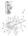
音響変換装置1は駆動ユニット2と振動板ユニット3と収納ユニット4から成る(図1乃至図3参照)。[overall structure]
The
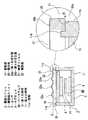
駆動ユニット2は、ヨーク5と一対のマグネット6、6とコイル7と回路基板8とアーマチュア9から成る(図2及び図3参照)。 The
ヨーク5は上下方向を向く平板状の第1の部材10と上方に開口されたコ字状の第2の部材11とが結合されて成る。第2の部材11は上下方向を向く底面部11aと該底面部11aの左右両端部からそれぞれ上方へ突出された側面部11b、11bとから成る。 The
第1の部材10は左右両側面がそれぞれ、例えば、接着等によって第2の部材11の側面部11b、11bにおける内面に取り付けられている。ヨーク5は第1の部材10と第2の部材11が結合されて前後に貫通された角筒状に形成され、前側の開口が作業用開口5aとして形成されている。 The left and right side surfaces of the
マグネット6、6は上下方向において離隔し互いに対向する状態で配置され、対向する側の極が異なる極にされている。上方に位置するマグネット6は第1の部材10の下面に取り付けられ、下方に位置するマグネット6は第2の部材11における底面部11aの上面に取り付けられている。 The
上記のように、ヨーク5は第1の部材10と第2の部材11によって構成されている。 As described above, the
従って、第1の部材10と第2の部材11の底面部11aとの距離を調整することが可能であり、良好な磁気特性を確保するために必要とされるマグネット6、6間の距離(図4に示すL)の最適化を図ることができる。特に、マグネット6、6間の距離Lは、マグネット6、6をヨーク5に取り付けるための接着剤の厚みや、マグネット6、6間に挿入されるアーマチュア9の後述する振動部の厚みに依存するため、マグネット6、6間の距離Lが調整可能とされていることは良好な磁気特性や良好な組立性の確保に極めて有用である。 Therefore, it is possible to adjust the distance between the
また、第1の部材10と第2の部材11を結合する前の状態において、第1の部材10と第2の部材11にそれぞれマグネット6、6を取り付けることが可能である。従って、枠状に一体に形成されたヨークの内部空間にマグネット6、6を挿入して取付作業を行う必要がなく、ヨーク5に対するマグネット6、6の取付作業を簡単かつ高精度で行うことができる。 Further, it is possible to attach the
尚、第1の部材10と第2の部材11の結合作業は、例えば、マグネット6、6間に図示しないスペーサーを挿入して行ったり、また、画像処理によって距離Lを確認することにより行われる。 The
上記には、ヨーク5を平板状の第1の部材10とコ字状の第2の部材11によって構成した例を示したが、ヨークの構成はこれに限られることはなく、例えば、以下のようなヨーク5A、5Bを構成することも可能である(図5及び図6参照)。 In the above, the example in which the
ヨーク5Aは下方に開口されたコ字状の第1の部材10Aと上方に開口されたコ字状の第2の部材11Aとによって構成されている(図5参照)。第1の部材10Aと第2の部材11Aは、例えば、外面側に配置されたアーマチュア9の後述する被固定部(16、16)に取り付けられて上下に離隔して配置されている。ヨーク5Aにあっても、ヨーク5と同様に、第1の部材10Aと第2の部材11Aの位置調整を行うことにより、マグネット6、6間の上下方向における距離の最適化を図ることができる。 The
ヨーク5Bは上下左右に位置する四つの平板状の第1の部材10B、10Bと第2の部材11B、11Bが結合されて成る(図6参照)。第1の部材10B、10Bは上下に離隔して位置され、第2の部材11B、11Bは左右に離隔して位置されている。ヨーク5Bにあっても、第1の部材10B、10B間の位置調整を行うことにより、マグネット6、6間の上下方向における距離の最適化を図ることができる。 The
このようにヨークを構成する部材の数は複数であれば任意であり、複数の部材が上下方向において距離の調整が可能とされることにより、マグネット6、6間の上下方向における距離の最適化を図ることができる。 Thus, the number of members constituting the yoke is arbitrary as long as it is plural, and the distance between the
コイル7は軸方向が前後方向にされた筒状に形成され、前後方向から見て、例えば、長穴状に形成されている(図1及び図3参照)。コイル7は整列巻きにされ、上面及び下面がそれぞれ平面状に形成された被取付面7a、7bとして形成されている。 The
回路基板8はコイル7の被取付面7aに取り付けられている。回路基板8は前後方向における長さがコイル7の前後方向における長さより長くされ、略前半部がコイル7の被取付面7aに取り付けられている。従って、回路基板8の略後半部はコイル7から後方へ突出されている。 The
回路基板8の図示しない一対の接続端子部にはそれぞれコイル7の両端部が接続され、一対の接続端子部にそれぞれコイル7の両端部が接続された状態において、回路基板8がコイル7の被取付面7aに接着等により取り付けられている。コイル7は整列巻きにされ被取付面7aが平面状に形成されているため、コイル7と回路基板8の良好な接合状態を確保することができる。 In a state where both ends of the
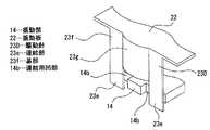
アーマチュア9は磁性金属材料によって各部が一体に形成されて成る。アーマチュア9は上下方向を向くコイル取付部12と該コイル取付部12の後端部から上方へ突出された連結部13と該連結部13の上端部から前方へ突出された振動部14とコイル取付部12の左右両端部からそれぞれ上方へ突出された側壁部15、15と該側壁部15、15の略上半部における前面からそれぞれ前方へ突出された被固定部16、16とが一体に形成されて成る。 Each part of the
振動部14は前後方向における長さがコイル取付部12の前後方向における長さより長くされ、前端がコイル取付部12の前端より前方に位置されている。振動部14の前面の左右方向における中央部には前方に開口された連結用凹部14aが形成されている。 The
側壁部15、15の上面と被固定部16、16の上面とは同一平面とされ、この左右に離隔して位置された同一平面がそれぞれ固定面17、17として形成されている。 The upper surfaces of the
コイル取付部12の上面には、例えば、接着によってコイル7が取り付けられる(図3及び図7参照)。コイル7は整列巻きにされ被取付面7bとされた下面が平面状に形成されているため、コイル取付部12に対するコイル7の良好な接合状態を確保することができる。 The
コイル7がコイル取付部12に取り付けられた状態においては、コイル7に振動部14が貫通され一部がコイル7から前方へ突出された状態とされている。 In a state where the
音響変換装置1にあっては、コイル7が取り付けられるコイル取付部12とコイル7に貫通される振動部14とが、何れもアーマチュア9に設けられている。従って、コイル7に対する振動部14の位置を高い精度で確保することができ、コイル7に対する振動部14の位置精度の向上を図ることができる。 In the
アーマチュア9はコイル取付部12にコイル7が取り付けられた状態において、ヨーク5の側面部11b、11bの外面にそれぞれ被固定部16、16が接着や溶着等によって固定される(図8参照)。 In the state in which the
アーマチュア9のヨーク5に対する固定作業の際に、良好な磁気バランスを確保するために、振動部14とマグネット6、6の位置調整が行われる。特に、音響変換装置1にあっては、ヨーク5が体積の異なる第1の部材10と第2の部材11によって構成されているため、上下方向において磁気バランスが不均衡になる可能性があるが、振動部14とマグネット6、6の位置調整を行うことにより良好な磁気バランスを確保することができる。 When the
振動部14とマグネット6、6の位置調整は、アーマチュア9とヨーク5の位置を調整することにより行う。具体的には、図4に示すように、一方のマグネット6と振動部14の上面との間隔H1及び他方のマグネット6と振動部14の下面との間隔H2の間隔調整やマグネット6、6に対する振動部14の傾き調整等を行う。 The position adjustment of the vibrating
このとき音響変換装置1にあっては、コイル7がアーマチュア9のコイル取付部12に取り付けられているため、コイル7に対する振動部14の位置が変化することがなく、振動部14とマグネット6、6の位置を調整することによりコイル7のマグネット6、6に対する位置が同時に調整される。 At this time, in the
従って、マグネット6,6に対するコイル7を事前に位置調整をする必要がなく、作業性の向上を図ることができる。 Therefore, it is not necessary to adjust the position of the
尚、音響変換装置1においては、ヨーク5が体積の異なる第1の部材10と第2の部材11によって構成されている。従って、例えば、第1の部材10と第2の部材11をそれぞれ異なる厚さに形成する、マグネット6、6をそれぞれ異なる厚さに形成する、マグネット6、6をそれぞれ異なる材料によって形成する、マグネット6、6をそれぞれ異なる磁力にする等の手段によって磁気バランスを調整してもよい。 In the
アーマチュア9がヨーク5に固定された状態においては、ヨーク5の側面部11b、11bの上面がアーマチュア9の固定面17、17より稍上方に位置される(図4参照)。また、振動部14の前端部に形成された連結用凹部14aがマグネット6、6の前端部の真下より稍前方に位置される。 In a state where the
尚、上記には、各部が一体に形成されたアーマチュア9を例として示したが、アーマチュアは磁化される部分である振動部が磁性金属材料によって形成されていればよく、例えば、以下のようなアーマチュア9A、9Bとして構成されていてもよい(図9及び図10参照)。 In the above, the
アーマチュア9Aは、図9に示すように、振動部14を含む第1部材18と被固定部16、16を含む第2の部材19とが接着又は溶着によって結合されることにより構成されている。 As shown in FIG. 9, the
アーマチュア9Bは、図10に示すように、振動部14を含む第1部材18がヨーク5の第2の部材11Aに接着又は溶着によって結合されることにより構成されている。 As shown in FIG. 10, the
このように振動部14を含む第1部材18を他の部分と異なる部材として構成することにより、例えば、磁化される必要のある高価な第1部材18とこれより安価に形成することが可能な他の部分とを各別に形成することができ、製造コストの低減を図ることができる。 By configuring the
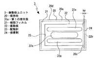
振動板ユニット2は保持枠20と樹脂フィルム21と振動板22と梁部23から成る(図1及び図3参照)。 The
保持枠20は、例えば、金属材料によって縦長の枠状に形成され、左右方向における幅がアーマチュア9の左右方向における幅と略同じにされている。保持枠20は下面が第1の接合面20aとされ上面が第2の接合面20bとされている。 For example, the holding
樹脂フィルム21は大きさが保持枠20の外形と同じにされ、例えば、保持枠20の開口を閉塞するように保持枠20の上面20b上に接着等により貼り付けられている。 The
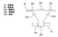
振動板22は厚みの薄い金属材料、例えば、アルミニウム又はステンレスによって外形が保持枠20の内形より一回り小さくされた矩形状に形成されている。振動板22には前後に延び左右に離隔して位置された補強リブ22a、22a、22aが設けられ、該補強リブ22a、22a、22aは上方へ打ち出された形状に形成されている。 The
振動板22は、例えば、下方から樹脂フィルム21に貼り付けられた状態とされている。 For example, the
振動板22の後端22bは保持枠20の後端部における内面20cより僅かに前方に位置され、振動板22の後端22bと保持枠20の後端部における内面20cとの間には隙間Mが形成されている(図11及び図12参照)。隙間Mは振動板22と保持枠20の寸法公差や組付誤差等により生じ、例えば、0.1mm程度である。 The
振動板ユニット3には隙間Mを埋めるようにして接着剤24が塗布されている。従って、振動板22と保持枠20は接着剤24と樹脂フィルム21を介して結合される。接着剤24としては、例えば、アクリル系の非硬化型接着剤やアクリル系の紫外線硬化型接着剤が用いられている。 An adhesive 24 is applied to the
尚、接着剤24は、隙間Mを埋めるとともに、振動板22の樹脂フィルム21に貼り付けられた側と反対側の面に延在されている。即ち、振動板22は樹脂フィルム21により保持枠20に支持されるが、これを補強する補強部材として機能する。 The adhesive 24 fills the gap M and extends on the surface of the
梁部23は振動板22と一体に形成されており、例えば、振動板22の一部が下方へ折り曲げられることにより形成されている。梁部23は、例えば、上下に延びる細幅の板状に形成されている。 The
振動板ユニット3は駆動ユニット2に上方から、例えば、接着又はレーザー溶着によって固定される。振動板ユニット3は保持枠20の第1の接合面20aがアーマチュア9の固定面17、17に接合されることにより固定される。 The
保持枠20の第1の接合面20aは、例えば、レーザー溶着によってアーマチュア9の固定面17、17に接合され、側方からレーザーRが接合部分に照射される(図13参照)。このとき、上記したように、ヨーク5の側面部11b、11bの上面がアーマチュア9の固定面17、17より稍上方に位置されており、レーザーRの照射によって溶融した金属m、m、・・・がヨーク5側へ飛散したときに、飛散した金属m、m、・・・が側面部11b、11bにおける上端部の外面に衝突する。 The first joining
従って、レーザーRの照射によって飛散した金属m、m、・・・の樹脂フィルム21への付着を防止することができ、樹脂フィルム21の破損を防止することができる。このようにヨーク5における側面部11bの上端部は金属m、m、・・・の飛散を防止する壁部11cとして機能し、該壁部11cの外面と保持枠20の内面とは可能な限り近付いて位置することが望ましい。 Therefore, adhesion of the metal m, m,... Scattered by the irradiation of the laser R to the
また、音響変換装置1にあっては、ヨーク5における側面部11bの上面をアーマチュア9の固定面17、17より上方に位置させることにより、樹脂フィルム21の破損を防止することができ、製造コストの高騰を来たすことなく簡単な手段によって樹脂フィルム21の破損を防止することができる。 Further, in the
尚、上記には、ヨーク5に金属m、m、・・・の飛散を防止する壁部11cを設けた例を示したが、例えば、図14に示すように、アーマチュア9の固定面17、17にそれぞれ上方へ突出された壁部17a、17aを設けることも可能である。 In the above, an example in which the
このようにアーマチュア9に壁部17a、17aを設けることにより、ヨーク5の上面とアーマチュア9の固定面17、17との高さを考慮することなく、アーマチュア9をヨーク5に固定することができ、設計の自由度の向上を図った上で樹脂フィルム21の破損を防止することができる。 By providing the
また、アーマチュア9に壁部17a、17aを設けることにより、固定面17、17がヨーク5より前後方向に長くされているため、レーザーRの照射範囲を広くして振動板ユニット2を駆動ユニット2に強固に固定することができる。 Further, by providing the
さらに、図10に示したアーマチュア9Bのように、被固定部16、16を有しない場合には、振動板ユニット3の保持枠20がヨーク5の上面に固定されるが、この場合には、図15に示すように、ヨーク5の側面部11b、11bの上端部にそれぞれ壁部11d、11dを設けることが可能である。 Further, as in the case of the
このようにヨーク5に保持枠20を固定しヨーク5に壁部11d、11dを設けることにより、アーマチュア9の被固定部16、16が存在しない分、音響変換装置1の小型化を図った上で樹脂フィルム21の破損を防止することができる。 In this way, the holding
上記のように、駆動ユニット2の振動板ユニット3への固定時には、梁部23の下端部をアーマチュア9における振動部14の前端部に接着によって取り付ける(図3参照)。梁部23は振動部14に形成された連結用凹部14aに挿入された状態で接着剤25によってアーマチュア9に連結される。 As described above, when the
上記したように、梁部23は振動板22に一体に形成されているため、梁部23の下端部を振動部14に取り付けるだけで梁部23を介して振動板22とアーマチュア9が連結され、振動板22と梁部23とアーマチュア9の連結作業における作業効率の向上を図ることができる。 As described above, since the
また、梁部23が振動板22に一体に形成されているため、梁部23の下端部をアーマチュア9の振動部14に取り付けた状態において梁部23の上端部を振動板22に取り付ける必要がない。従って、梁部23の上端部を振動板22の下面に手探りで取り付ける必要がなく、梁部23の振動板22に対する連結位置のずれ、梁部23の変形、梁部23の振動板22に対する屈曲等が生じることがなく、歩留まりの向上を図ることができる。 Further, since the
さらに、音響変換装置1にあっては、ヨーク5が前後に貫通された角筒状に形成され、前側の開口が作業用開口5aとして形成されているため、作業用開口5aから梁部23の振動部14に対する取付作業を行うことができ、作業性の向上を図ることができる。また、ヨーク5に作業用開口5aが形成されているため、梁部23を振動部14に接着する接着剤25として紫外線硬化型接着剤を用いることができ、梁部23の振動部14への連結作業における作業性の向上を図ることができる。 Furthermore, in the
尚、上記には、梁部23の例として上下に延びる細幅の板状の形状を例として示したが、梁部23の形状は細幅の板状に限られることはなく、例えば、図16乃至図19に示す梁部23A、23B、23C、23Dのように、各種の形状に形成することが可能である。 In the above, a narrow plate-like shape extending up and down is shown as an example of the
梁部23Aは、図16に示すように、下端部が振動部14に連結される細幅の連結部23aとして設けられ、連結部23aの上側の部分が上方へ行くに従って左右方向における幅が大きくなる基部23bとして設けられている。 As shown in FIG. 16, the
このように梁部23Aは上方へ行くに従って左右方向における幅が大きくなる基部23bを有しているため、強度が高く振動部14において発生した振動を振動板22に確実に伝達することができる。 Thus, since the
梁部23Bは、図17に示すように、下端部が振動部14に連結される細幅の連結部23cとして設けられ、連結部23cの上側の部分が連結部23cより左右方向における幅が大きい基部23dとして設けられている。 As shown in FIG. 17, the
このように梁部23Bは連結部23cより幅の広い基部23dを有しているため、強度が高く振動部14において発生した振動を振動板22に確実に伝達することができる。 Thus, since the
梁部23Cは、図18に示すように、下端部が振動部14に連結され左右に離隔して位置された細幅の連結部23e、23eとして設けられ、連結部23e、23eの上側の部分が連結部23e、23eより左右方向における幅が大きい基部23fとして設けられている。梁部23Cは左右に離隔して位置された細幅の連結部23e、23eを有しているため、振動部14には左右に離隔して位置された二つの連結用凹部14b、14bが設けられている。 As shown in FIG. 18, the beam portion 23C is provided as
このように梁部23Cは連結部23e、23eより幅の広い基部23fを有しているため、強度が高く振動部14において発生した振動を振動板22に確実に伝達することができる。また、左右に離隔して位置された連結部23e、23eを有しているため、振動部14との連結状態の安定化を図ることができる。 Thus, since the beam portion 23C has the
梁部23Dは、図19に示すように、梁部23Cに対して基部23fの中央部が前方又は後方へ凸の円弧面状に形成された屈曲部23gとして設けられている。 As shown in FIG. 19, the beam portion 23D is provided as a
このように梁部23Dは円弧面状に形成された屈曲部23gを有しているため、一層強度を高くすることができる。 Thus, since beam part 23D has the bending
尚、梁部23(23A、23B、23C、23D)は振動板22と一体に形成されており、アルミニウム又はステンレスによって形成されている。 The beam portion 23 (23A, 23B, 23C, 23D) is formed integrally with the
振動板22をアルミニウムによって形成することにより軽量化を図ることができる。一方、振動板22をステンレスによって形成することにより強度を高くして振動部14から振動板22への振動の伝達効率の向上を図ることができる。 The weight can be reduced by forming the
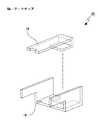
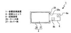
収納ユニット4は上方に開口された箱状のケース体26と下方に開口された浅い箱状のカバー体27とから成る(図1乃至図3参照)。 The
ケース体26には後面部28の上端部に上方に開口された挿通用切欠28aが形成されている。ケース体26の前後両端部における内面側には、それぞれ上方を向く載置用段差面26a、26a、26aが形成されている。 The
カバー体27には前面部29に前後に貫通された音声出力孔29aが形成されている。 The
[音響変換装置の組立方法]
以下に、音響変換装置1の組立方法について説明する(図20乃至図25参照)。[Assembly method of acoustic transducer]
Below, the assembly method of the
先ず、上記したように、ヨーク5、マグネット6、6、コイル7、回路基板8及びアーマチュア9によって駆動ユニット2を組み立て、保持枠20、樹脂フィルム21、振動板22及び梁部23によって振動板ユニット3を組み立てる(図20参照)。 First, as described above, the
次に、上記したように、駆動ユニット2に振動板ユニット3を固定する(図21参照)。駆動ユニット2の振動板ユニット3への固定はアーマチュア9の固定面17、17に保持枠20の第1の接合面20aを接合することにより行う。このとき梁部23の下端部をアーマチュア9における振動部14の前端部に接着剤25によって取り付ける。 Next, as described above, the
次いで、駆動ユニット2と振動板ユニット3をケース体26に上方から収納する(図22参照)。ケース体26に収納された振動板ユニット3は保持枠20の前後両端部がそれぞれケース体26の載置用段差面26a、26a、26aに載置されて位置決めされる。このとき駆動ユニット2の下面とケース体26の底面部の上面との間には所定の隙間が形成される。 Next, the
駆動ユニット2と振動板ユニット3がケース体26に収納された状態においては、保持枠20の第2の接合面20bがケース体26の上端面26bの直ぐ内側において稍下方に位置される(図23参照)。このとき保持枠20の外面20dとケース体26の内面26cとの間に隙間Sが形成されている。 In a state where the
また、駆動ユニット2と振動板ユニット3がケース体26に収納された状態においては、コイル7に取り付けられた回路基板8の略後半部がケース体26の挿通用切欠28aから後方へ突出されている。 In a state where the
次に、保持枠20の第2の接合面20bにシール剤30を装填する(図24参照)。シール剤30は、例えば、接着作用も有している。 Next, the sealing
次いで、カバー体27を第2の接合面20bに装填したシール剤30に上方から押し付けて押し潰す(図25参照)。シール剤30を押し潰すと、該シール剤30が保持枠20の外面20dとケース体26の内面26cとの間の隙間及びカバー体27の外面27aとケース体26の内面26cとの間の隙間に侵入し、隙間Sが封止される。また、シール剤30は保持枠20の第2の接合面20bとカバー体27の下端面27bとの間に残存する他、保持枠20の内側にも侵入し保持枠20とカバー体27との間の隙間が封止される。 Next, the
従って、カバー体27をシール剤30に上方から押し付けて押し潰すことにより、保持枠20とカバー体27とケース体26との間の各隙間が封止され、これらの三者が接着されて結合される。 Therefore, by pressing the
このとき、カバー体27の下面がケース体26の上面より低く、かつ、内側に配置される。 At this time, the lower surface of the
このように音響変換装置1にあっては、カバー体27によって保持枠20を覆いシール剤30を押し潰すだけの一度の作業を行うことにより、保持枠20とカバー体27とケース体26との間の各隙間が封止され、音響変換装置1の組立作業における作業性の向上を図ることができる。 As described above, in the
次いで、ケース体26における挿通用切欠28aの開口縁と回路基板8との間の隙間にシール剤(接着剤)31を塗布して封止及び接着を行う(図26参照)。 Next, a sealing agent (adhesive) 31 is applied to a gap between the opening edge of the
最後に、回路基板8のケース体26から後方へ突出された部分に、コイル7に電源を供給するための接続コードや接続端子を接続する。 Finally, a connection cord or a connection terminal for supplying power to the
音響変換装置1にあっては、上記したように、回路基板8をコイル7に貼り付けて接続しているため、配線の引き回し作業を必要とせず、作業効率の向上を図ることができる。 In the
尚、回路基板8には接続コードや接続端子が接続されるプラス極とマイナス極の一対の端子部8a、8bが設けられており、該端子部8a、8bはそれぞれ回路基板8の表裏に位置されている(図27参照)。 The
このように端子部8a、8bをそれぞれ回路基板8の表裏に設けることにより、接続コードや接続端子の接続時、特に、半田付けによって接続する際の短絡を防止することができる。 Thus, by providing the
また、回路基板8に端子部8a、8bをそれぞれ表裏に設けた状態で前後に離隔して位置させてもよく(図28参照)、端子部8a、8bを表面又は裏面の一方に設けた状態で前後に離隔して位置させてもよい(図29参照)。 In addition, the
このように端子部8a、8bを前後に離隔して位置させた場合にも、接続コードや接続端子の接続時における短絡を防止することができる。 As described above, even when the
尚、上記には、樹脂フィルム21が貼り付けられた保持枠20をケース体26とカバー体27の間に取り付けた例を示したが、保持枠20を設けることなく樹脂フィルム21がケース体26とカバー体27の間に貼り付けられる構成とすることも可能である。 In addition, although the example which attached the holding
[音響特性]
音響変換装置1にあっては、コイル7に電流が供給されると、一対のマグネット6、6間に位置するアーマチュア9の振動部14が磁化され、該振動部14の極性がマグネット6、6に対向する位置において繰り返し変化される。極性が繰り返し変化されることにより振動部14に微少な振動が発生し、発生した振動が梁部23から振動板22に伝達され、伝達された振動が振動板22において増幅されて音声に変換されカバー体27の音声出力孔29aから出力される。[Acoustic characteristics]
In the
このとき、出力される音声の周波数領域において音圧のバラツキを制して音響特性の向上を図るためには、当該周波数領域、特に、高周波数領域に存在する三次共振ピークを明確に出現させることが望ましい。 At this time, in order to control the variation of sound pressure in the frequency region of the output sound and improve the acoustic characteristics, the third resonance peak that exists in the frequency region, particularly in the high frequency region, should appear clearly. Is desirable.
音響変換装置1にあっては、上記したように、振動板22の後端22bが保持枠20の後端部における内面20cより僅かに前方に位置され、振動板22の後端22bと保持枠20の後端部における内面20cとの間の隙間Mが埋められるように接着剤24が塗布されている(図11及び図12参照)。従って、振動板22と保持枠20が接着剤24と樹脂フィルム21を介して結合された状態とされている。 In the
このように振動板22の後端22bと保持枠20の内面20cとの間の隙間Mを埋めるように接着剤24を塗布することにより、接着剤24が塗布された部分が三次共振を発生するための明確な支点(振動支点)Pとなる(図30参照)。従って、音響変換装置1における周波数領域、特に、高周波数領域の音圧のバラツキが抑制され、安定した音圧を得ることができ、音響特性の向上を図ることができる。 In this way, by applying the adhesive 24 so as to fill the gap M between the
以下に、音響特性を測定した結果について説明する(図31及び図32参照)。 The results of measuring the acoustic characteristics will be described below (see FIGS. 31 and 32).
図31及び図32は、横軸に周波数(Hz)を示し、縦軸に感度(dB)を示したグラフ図である。 31 and 32 are graphs showing the frequency (Hz) on the horizontal axis and the sensitivity (dB) on the vertical axis.
図31において、Aは隙間Mを0.14mmとし隙間Mに接着剤を塗布しない状態、Bは隙間Mを0.07mmとし隙間Mに接着剤を塗布しない状態、Cは隙間Mを0.07mmとし隙間Mに接着剤を塗布した状態を示す。Cにおいて用いた接着剤はアクリル系の非硬化型接着剤(感圧型接着剤)であり、粘度が100〜3000mPa・sとされている。 In FIG. 31, A is a state where the gap M is 0.14 mm and no adhesive is applied to the gap M, B is a state where the gap M is 0.07 mm and no adhesive is applied to the gap M, and C is a gap M of 0.07 mm. A state where an adhesive is applied to the gap M is shown. The adhesive used in C is an acrylic non-curable adhesive (pressure-sensitive adhesive), and has a viscosity of 100 to 3000 mPa · s.
図31のAとBの比較により、3000〜4000Hz以下の周波数領域においては感度にほとんど差が見られないが、高周波領域においては隙間Mが大きくなると感度が低下することが解る。 From comparison between A and B in FIG. 31, it is understood that there is almost no difference in sensitivity in the frequency region of 3000 to 4000 Hz or less, but in the high frequency region, the sensitivity decreases as the gap M increases.
また、図31のBとCの比較により、隙間Mが一定の場合に、3000〜4000Hz以下の周波数領域においては接着剤の塗布の有無によっては感度にほとんど差が見られないが、高周波領域においては接着剤の塗布によって感度が高くなることが解る。 Further, by comparing B and C in FIG. 31, when the gap M is constant, in the frequency range of 3000 to 4000 Hz, there is almost no difference in sensitivity depending on whether or not the adhesive is applied. It can be seen that the sensitivity is increased by applying the adhesive.
図32は、隙間Mの値を一定にし隙間Mに塗布する接着剤を変更したときの測定結果である。 FIG. 32 shows measurement results when the value of the gap M is constant and the adhesive applied to the gap M is changed.
図32において、Dは図31のCと同じアクリル系の非硬化型接着剤を隙間Mに塗布した状態、Eは硬度がD(ショアー)75であるアクリル系の紫外線硬化型接着剤を隙間Mに塗布した状態、Fは硬度がD(ショアー)85であるアクリル系の紫外線硬化型接着剤を隙間Mに塗布した状態を示す。Dの非硬化型接着剤の硬度はEの紫外線硬化型の接着剤の硬度より低い。 32, D is a state where the same acrylic non-curable adhesive as C in FIG. 31 is applied to the gap M, and E is an acrylic ultraviolet curable adhesive having a hardness of D (Shore) 75. F indicates a state in which an acrylic ultraviolet curable adhesive having a hardness of D (Shore) 85 is applied to the gap M. The hardness of the non-curing adhesive of D is lower than the hardness of the ultraviolet curing adhesive of E.
図32のA、B、Cの比較により、3000〜4000Hz以下の周波数領域においては硬度の低い接着剤の方が感度が高く、10000Hz以上の周波数領域においては硬度の高い接着剤の方が感度が高くなることが解る。 Comparison of A, B, and C in FIG. 32 shows that the adhesive with lower hardness has a higher sensitivity in the frequency region of 3000 to 4000 Hz or lower, and the adhesive with higher hardness has a higher sensitivity in the frequency region of 10,000 Hz or higher. It turns out that it becomes high.
上記した測定結果より、接着剤24として非硬化型接着剤を用いることにより、低域感度を落とさずに、高域において感度の向上を図ることができ、音響特性の向上を図ることができる。 From the above measurement results, by using a non-curable adhesive as the adhesive 24, it is possible to improve the sensitivity in the high frequency range without reducing the low frequency sensitivity, and to improve the acoustic characteristics.
また、接着剤24として紫外線硬化型接着剤を用いることにより、高域において感度の向上を図ることができ、音響特性の向上を図ることができる。 Further, by using an ultraviolet curable adhesive as the adhesive 24, it is possible to improve the sensitivity at high frequencies and improve the acoustic characteristics.
特に、接着剤24としてアクリル系の紫外線硬化型接着剤を用いることにより、良好な接着強度及び接着作業の短縮化を確保した上で音響特性の向上を図ることができる。 In particular, by using an acrylic ultraviolet curable adhesive as the adhesive 24, it is possible to improve the acoustic characteristics while ensuring good adhesive strength and shortening of the adhesive work.
上記した最良の形態において示した各部の具体的な形状及び構造は、何れも本発明を実施する際の具体化のほんの一例を示したものにすぎず、これらによって本発明の技術的範囲が限定的に解釈されることがあってはならないものである。 The specific shapes and structures of the respective parts shown in the above-described best mode are merely examples of the implementation of the present invention, and the technical scope of the present invention is limited by these. It should not be interpreted in a general way.
1…音響変換装置、2…駆動ユニット、3…振動板ユニット、4…収納ユニット、5…ヨーク、6…マグネット、7…コイル、9…アーマチュア、14…振動部、18a…連結用凹部、20…保持枠、20c…内面、21…樹脂フィルム、22…振動板、22b…後端(他端)、23…梁部、26…ケース体、27…カバー体、5A…ヨーク、5B…ヨーク、9A…アーマチュア、9B…アーマチュア、23A…梁部、23B…梁部、23C…梁部、23D…梁部、24…接着剤(補強部材)、29a…音声出力孔、M…隙間、P…振動支点DESCRIPTION OF
Claims (8)
Translated fromJapanese開口を有する保持枠と、前記保持枠の開口を覆う状態で前記保持枠に貼り付けられた樹脂フィルムと、前記樹脂フィルムに貼り付けられた状態で前記保持枠の内側に保持された振動板と、両端部がそれぞれ前記振動板と前記アーマチュアの振動部とに連結され前記振動部の振動を前記振動板に伝達する梁部とを有する振動板ユニットとを備え、
前記梁部は前記振動板の一端側に連結され、
前記振動板の他端と前記保持枠の内面との間に所定の隙間が形成され、
前記所定の隙間に補強部材を設け、
前記振動板が前記樹脂フィルムと前記補強部材とによって前記保持枠に結合された
音響変換装置。A pair of magnets arranged opposite to each other, a yoke to which the pair of magnets are attached, a coil to which a drive current is supplied, and a vibration unit that vibrates when the drive current is supplied to the coil are provided. A drive unit having an armature that is disposed between the pair of magnets through the coil and is fixed to the yoke;
A holding frame having an opening; a resin film attached to the holding frame in a state of covering the opening of the holding frame; and a diaphragm held inside the holding frame in a state of being attached to the resin film; A vibration plate unit having both ends connected to the vibration plate and the vibration portion of the armature and having beam portions that transmit the vibration of the vibration portion to the vibration plate,
The beam portion is connected to one end side of the diaphragm,
A predetermined gap is formed between the other end of the diaphragm and the inner surface of the holding frame;
A reinforcing member is provided in the predetermined gap,
An acoustic conversion device in which the diaphragm is coupled to the holding frame by the resin film and the reinforcing member.
請求項1に記載の音響変換装置。By providing the reinforcing member in the predetermined gap between the other end of the diaphragm and the inner surface of the holding frame, the third resonance that exists in the frequency region of the sound in which the portion provided with the reinforcing member is output. The acoustic conversion device according to claim 1, wherein the acoustic conversion device isa vibration fulcrum for generating noise .
請求項1又は請求項2に記載の音響変換装置。The acoustic conversion device according toclaim 1, wherein the holding frame is fixed to the drive unit.
請求項1又は請求項2に記載の音響変換装置。And a housing unit having a case body and a cover body for housing the drive unit and the diaphragm unit, and having an audio output hole for outputting sound generated when vibration is transmitted to the diaphragm. The acoustic conversion device according toclaim 1or 2 .
請求項1又は請求項2に記載の音響変換装置。The acoustic conversion device according toclaim 1, wherein a non-curable adhesive is used as the reinforcing member.
請求項5に記載の音響変換装置。The acoustic conversion device according to claim5 , wherein an acrylic adhesive is used as the non-curable adhesive.
請求項1又は請求項2に記載の音響変換装置。The acoustic conversion device according toclaim 1, wherein an ultraviolet curable adhesive is used as the reinforcing member.
請求項7に記載の音響変換装置。The acoustic conversion device according to claim7 , wherein an acrylic adhesive is used as the ultraviolet curable adhesive.
Priority Applications (3)
| Application Number | Priority Date | Filing Date | Title |
|---|---|---|---|
| JP2010137899AJP5540921B2 (en) | 2010-06-17 | 2010-06-17 | Acoustic transducer |
| US13/110,084US8634587B2 (en) | 2010-06-17 | 2011-05-18 | Acoustic conversion device |
| CN201110156304.3ACN102291650B (en) | 2010-06-17 | 2011-06-10 | sound conversion device |
Applications Claiming Priority (1)
| Application Number | Priority Date | Filing Date | Title |
|---|---|---|---|
| JP2010137899AJP5540921B2 (en) | 2010-06-17 | 2010-06-17 | Acoustic transducer |
Publications (2)
| Publication Number | Publication Date |
|---|---|
| JP2012004853A JP2012004853A (en) | 2012-01-05 |
| JP5540921B2true JP5540921B2 (en) | 2014-07-02 |
Family
ID=45328706
Family Applications (1)
| Application Number | Title | Priority Date | Filing Date |
|---|---|---|---|
| JP2010137899AExpired - Fee RelatedJP5540921B2 (en) | 2010-06-17 | 2010-06-17 | Acoustic transducer |
Country Status (3)
| Country | Link |
|---|---|
| US (1) | US8634587B2 (en) |
| JP (1) | JP5540921B2 (en) |
| CN (1) | CN102291650B (en) |
Families Citing this family (19)
| Publication number | Priority date | Publication date | Assignee | Title |
|---|---|---|---|---|
| JP4902784B2 (en)* | 2008-03-31 | 2012-03-21 | 三菱電機エンジニアリング株式会社 | Electromagnetic transducer |
| US20130272564A1 (en)* | 2012-03-16 | 2013-10-17 | Knowles Electronics, Llc | Receiver with a non-uniform shaped housing |
| CN103067836A (en)* | 2012-12-25 | 2013-04-24 | 苏州恒听电子有限公司 | Moving-iron unit with integrate conduction rod and preparation method of integrate conduction rod |
| CN103152675A (en)* | 2013-01-31 | 2013-06-12 | 苏州恒听电子有限公司 | Moving-iron unit with riveting type conduction bar |
| US9137605B2 (en)* | 2013-06-17 | 2015-09-15 | Knowles Electronics, Llc | Formed diaphragm frame for receiver |
| US9432774B2 (en)* | 2014-04-02 | 2016-08-30 | Sonion Nederland B.V. | Transducer with a bent armature |
| US9888322B2 (en) | 2014-12-05 | 2018-02-06 | Knowles Electronics, Llc | Receiver with coil wound on a stationary ferromagnetic core |
| CN104581579A (en)* | 2014-12-31 | 2015-04-29 | 苏州恒听电子有限公司 | Improved small-size receiver |
| CN104581572A (en)* | 2014-12-31 | 2015-04-29 | 苏州恒听电子有限公司 | Novel telephone receiver with anti-collision function and anti-vibration function |
| CN104581581A (en)* | 2014-12-31 | 2015-04-29 | 苏州恒听电子有限公司 | Novel improved small-size telephone receiver |
| CN104581571A (en)* | 2014-12-31 | 2015-04-29 | 苏州恒听电子有限公司 | Telephone receiver with high-loudness sound quality |
| JP6717306B2 (en)* | 2015-07-29 | 2020-07-01 | ソニー株式会社 | Audio output device |
| US10149060B2 (en)* | 2015-11-20 | 2018-12-04 | Aac Acoustic Technologies (Shenzhen) Co., Ltd. | Long stroke speaker |
| CN106714053B (en)* | 2016-11-29 | 2023-01-10 | 深圳倍声声学技术有限公司 | Moving-iron type telephone receiver |
| US10699833B2 (en)* | 2016-12-28 | 2020-06-30 | Sonion Nederland B.V. | Magnet assembly |
| CN106954148B (en)* | 2017-03-20 | 2018-12-14 | 歌尔股份有限公司 | A kind of sounding device and electronic equipment |
| US10229749B2 (en) | 2017-03-31 | 2019-03-12 | Samsung Electronics Co., Ltd. | Nonvolatile memory storage system |
| CN107071666A (en)* | 2017-05-08 | 2017-08-18 | 佛山市川东磁电股份有限公司 | One kind rectilinear movement dibit bistable electromagnetic switch |
| CN120568258B (en)* | 2025-07-30 | 2025-09-30 | 苏州迪倍电子科技有限公司 | Vibrating diaphragm moving iron unit based on magnesium-lithium alloy and multistage stamping forming die |
Family Cites Families (37)
| Publication number | Priority date | Publication date | Assignee | Title |
|---|---|---|---|---|
| US3560667A (en)* | 1968-05-01 | 1971-02-02 | Industrial Research Prod Inc | Transducer having an armature arm split along its length |
| JPS507927B1 (en)* | 1969-05-29 | 1975-03-31 | ||
| US4473722B1 (en)* | 1982-06-07 | 1995-06-20 | Knowles Electronics Co | Electroacoustic transducers |
| JPS6052198A (en)* | 1983-08-31 | 1985-03-25 | Pioneer Electronic Corp | speaker |
| JPH0238558Y2 (en)* | 1984-10-18 | 1990-10-17 | ||
| NL8900613A (en)* | 1989-03-14 | 1990-10-01 | Microtel Bv | ACOUSTIC TRANSDUCER. |
| US5284893A (en)* | 1989-10-13 | 1994-02-08 | Daikin Industries, Ltd. | Coating composition |
| JPH089991Y2 (en)* | 1990-08-31 | 1996-03-21 | 株式会社オーディオテクニカ | Dynamic microphone |
| EP0716800A1 (en)* | 1993-09-01 | 1996-06-19 | Knowles Electronics, Inc. | Receiver for a hearing aid |
| NL1004669C2 (en)* | 1996-12-02 | 1998-06-03 | Microtronic Nederland Bv | Transducer. |
| WO2000003874A1 (en)* | 1998-07-14 | 2000-01-27 | Dai Nippon Printing Co., Ltd. | Decorative material |
| US7706561B2 (en)* | 1999-04-06 | 2010-04-27 | Sonion Nederland B.V. | Electroacoustic transducer with a diaphragm and method for fixing a diaphragm in such transducer |
| DE60017710T2 (en)* | 1999-11-10 | 2005-12-22 | Mitsui Mining & Smelting Co., Ltd. | METHOD FOR PRODUCING A NICKEL POWDER |
| ATE388600T1 (en)* | 2000-01-27 | 2008-03-15 | Nxp Bv | ELECTROACOUSTIC TRANSDUCER WITH MOVABLE COIL AND WITH ELASTIC FASTENING ELEMENTS FOR THE MOVABLE COIL CONNECTION CONTACTS |
| JP4260333B2 (en)* | 2000-03-16 | 2009-04-30 | スター精密株式会社 | Electroacoustic transducer |
| US7817815B2 (en)* | 2000-05-09 | 2010-10-19 | Knowles Electronics, Llc | Armature for a receiver |
| JP2001326995A (en)* | 2000-05-17 | 2001-11-22 | Star Micronics Co Ltd | Electromagnetic-acoustic transducer |
| TW510139B (en)* | 2001-01-26 | 2002-11-11 | Kirk Acoustics As | An electroacoustic transducer and a coil and a magnet circuit therefor |
| US6526153B2 (en)* | 2001-02-08 | 2003-02-25 | Tibbetts Industries, Inc. | Armature assembly for balanced moving armature magnetic transducer and method of locating and adjusting same |
| JP2002300698A (en)* | 2001-04-02 | 2002-10-11 | Star Micronics Co Ltd | Receiver and portable communication apparatus |
| US6727789B2 (en)* | 2001-06-12 | 2004-04-27 | Tibbetts Industries, Inc. | Magnetic transducers of improved resistance to arbitrary mechanical shock |
| US7132597B2 (en)* | 2002-02-26 | 2006-11-07 | Taylor-Listug, Inc. | Transducer for converting between mechanical vibration and electrical signal |
| US6762260B2 (en)* | 2002-03-05 | 2004-07-13 | Dow Global Technologies Inc. | Organoborane amine complex polymerization initiators and polymerizable compositions |
| JP3992275B2 (en)* | 2002-05-16 | 2007-10-17 | オンキヨー株式会社 | Small speaker |
| CN2563877Y (en)* | 2002-07-12 | 2003-07-30 | 天津市大德喷泉科技有限公司 | Moving-iron type momentum transducer |
| PL1627550T3 (en)* | 2003-05-09 | 2010-04-30 | Knowles Electronics Llc | Apparatus and method for generating acoustic energy in a receiver assembly |
| KR100547357B1 (en)* | 2004-03-30 | 2006-01-26 | 삼성전기주식회사 | Speaker for mobile terminal and manufacturing method thereof |
| JP2006041768A (en)* | 2004-07-26 | 2006-02-09 | Rion Co Ltd | Electroacoustic transducer |
| JP4210677B2 (en) | 2005-09-08 | 2009-01-21 | リオン株式会社 | Electroacoustic transducer and hearing aid using the same |
| US7899203B2 (en)* | 2005-09-15 | 2011-03-01 | Sonion Nederland B.V. | Transducers with improved viscous damping |
| JP4735405B2 (en)* | 2005-09-21 | 2011-07-27 | パナソニック株式会社 | Speaker damper and speaker using the same |
| JP4569476B2 (en)* | 2006-01-17 | 2010-10-27 | パナソニック株式会社 | Speaker |
| JP4735306B2 (en)* | 2006-02-09 | 2011-07-27 | パナソニック株式会社 | Speaker |
| EP1962550A3 (en)* | 2007-02-20 | 2009-03-04 | Sonion Nederland B.V. | A moving armature receiver with reduced parasitic coupling |
| US20090074226A1 (en)* | 2007-09-14 | 2009-03-19 | William Chris Eaton | Pcb with embedded speaker assembly |
| US8494209B2 (en)* | 2009-05-11 | 2013-07-23 | Knowles Electronics, Llc | Low axial vibration receiver armature and assembly |
| US20120135225A1 (en)* | 2009-08-18 | 2012-05-31 | Andre Colas | Multi-layer Transdermal Patch |
- 2010
- 2010-06-17JPJP2010137899Apatent/JP5540921B2/ennot_activeExpired - Fee Related
- 2011
- 2011-05-18USUS13/110,084patent/US8634587B2/ennot_activeExpired - Fee Related
- 2011-06-10CNCN201110156304.3Apatent/CN102291650B/ennot_activeExpired - Fee Related
Also Published As
| Publication number | Publication date |
|---|---|
| US20110311091A1 (en) | 2011-12-22 |
| CN102291650A (en) | 2011-12-21 |
| US8634587B2 (en) | 2014-01-21 |
| CN102291650B (en) | 2015-11-04 |
| JP2012004853A (en) | 2012-01-05 |
Similar Documents
| Publication | Publication Date | Title |
|---|---|---|
| JP5540921B2 (en) | Acoustic transducer | |
| JP5540920B2 (en) | Acoustic transducer | |
| JP5447216B2 (en) | Acoustic transducer and method for assembling acoustic transducer | |
| JP5598109B2 (en) | Acoustic transducer | |
| US8526659B2 (en) | Earphone and acoustic transducer | |
| JP6717306B2 (en) | Audio output device | |
| JP6883216B2 (en) | Sound converter and audio output device | |
| JP2006041768A (en) | Electroacoustic transducer | |
| JP4091006B2 (en) | Electroacoustic transducer | |
| JP6014787B1 (en) | Sound generator | |
| JP2006186615A (en) | Electric oscillation transducer | |
| JPWO2004030406A1 (en) | Electroacoustic transducer | |
| CN212344046U (en) | Balanced armature device | |
| JP2019092113A (en) | Sound producing device | |
| US20050279566A1 (en) | Loudspeaker | |
| CN214101762U (en) | speaker | |
| WO2019098181A1 (en) | Sound production device | |
| JP2019193080A (en) | Sound production device |
Legal Events
| Date | Code | Title | Description |
|---|---|---|---|
| A621 | Written request for application examination | Free format text:JAPANESE INTERMEDIATE CODE: A621 Effective date:20130423 | |
| A977 | Report on retrieval | Free format text:JAPANESE INTERMEDIATE CODE: A971007 Effective date:20131225 | |
| A131 | Notification of reasons for refusal | Free format text:JAPANESE INTERMEDIATE CODE: A131 Effective date:20140107 | |
| A521 | Request for written amendment filed | Free format text:JAPANESE INTERMEDIATE CODE: A523 Effective date:20140225 | |
| TRDD | Decision of grant or rejection written | ||
| A01 | Written decision to grant a patent or to grant a registration (utility model) | Free format text:JAPANESE INTERMEDIATE CODE: A01 Effective date:20140408 | |
| A61 | First payment of annual fees (during grant procedure) | Free format text:JAPANESE INTERMEDIATE CODE: A61 Effective date:20140421 | |
| R151 | Written notification of patent or utility model registration | Ref document number:5540921 Country of ref document:JP Free format text:JAPANESE INTERMEDIATE CODE: R151 | |
| R250 | Receipt of annual fees | Free format text:JAPANESE INTERMEDIATE CODE: R250 | |
| R250 | Receipt of annual fees | Free format text:JAPANESE INTERMEDIATE CODE: R250 | |
| R250 | Receipt of annual fees | Free format text:JAPANESE INTERMEDIATE CODE: R250 | |
| R250 | Receipt of annual fees | Free format text:JAPANESE INTERMEDIATE CODE: R250 | |
| LAPS | Cancellation because of no payment of annual fees |