JP5540113B2 - Method of manufacturing an implantable lead with an integral silicone part - Google Patents
Method of manufacturing an implantable lead with an integral silicone partDownload PDFInfo
- Publication number
- JP5540113B2 JP5540113B2JP2012547090AJP2012547090AJP5540113B2JP 5540113 B2JP5540113 B2JP 5540113B2JP 2012547090 AJP2012547090 AJP 2012547090AJP 2012547090 AJP2012547090 AJP 2012547090AJP 5540113 B2JP5540113 B2JP 5540113B2
- Authority
- JP
- Japan
- Prior art keywords
- preform
- lumen
- electrodes
- lead
- outer diameter
- Prior art date
- Legal status (The legal status is an assumption and is not a legal conclusion. Google has not performed a legal analysis and makes no representation as to the accuracy of the status listed.)
- Expired - Fee Related
Links
- 238000004519manufacturing processMethods0.000titleclaimsdescription12
- 229920001296polysiloxanePolymers0.000titledescription33
- 238000000034methodMethods0.000claimsdescription46
- WABPQHHGFIMREM-UHFFFAOYSA-Nlead(0)Chemical compound[Pb]WABPQHHGFIMREM-UHFFFAOYSA-N0.000claimsdescription38
- 238000000465mouldingMethods0.000claimsdescription11
- 229920000642polymerPolymers0.000claimsdescription10
- 239000004944Liquid Silicone RubberSubstances0.000claimsdescription8
- 238000000151depositionMethods0.000claimsdescription8
- 229920002379silicone rubberPolymers0.000claimsdescription8
- 230000008569processEffects0.000claimsdescription5
- 239000004020conductorSubstances0.000description74
- 239000000463materialSubstances0.000description11
- 230000007704transitionEffects0.000description11
- 229920002635polyurethanePolymers0.000description8
- 239000004814polyurethaneSubstances0.000description8
- 238000012986modificationMethods0.000description4
- 230000004048modificationEffects0.000description4
- 230000006835compressionEffects0.000description3
- 238000007906compressionMethods0.000description3
- 239000000853adhesiveSubstances0.000description2
- 230000001070adhesive effectEffects0.000description2
- 238000009413insulationMethods0.000description2
- 230000002093peripheral effectEffects0.000description2
- 238000007792additionMethods0.000description1
- 238000005452bendingMethods0.000description1
- 239000000560biocompatible materialSubstances0.000description1
- 230000007797corrosionEffects0.000description1
- 238000005260corrosionMethods0.000description1
- 230000007423decreaseEffects0.000description1
- 230000009977dual effectEffects0.000description1
- 238000010292electrical insulationMethods0.000description1
- 239000011796hollow space materialSubstances0.000description1
- 238000001746injection mouldingMethods0.000description1
- 230000009467reductionEffects0.000description1
Images


Classifications
- A—HUMAN NECESSITIES
- A61—MEDICAL OR VETERINARY SCIENCE; HYGIENE
- A61N—ELECTROTHERAPY; MAGNETOTHERAPY; RADIATION THERAPY; ULTRASOUND THERAPY
- A61N1/00—Electrotherapy; Circuits therefor
- A61N1/02—Details
- A61N1/04—Electrodes
- A61N1/05—Electrodes for implantation or insertion into the body, e.g. heart electrode
- A61N1/056—Transvascular endocardial electrode systems
- A—HUMAN NECESSITIES
- A61—MEDICAL OR VETERINARY SCIENCE; HYGIENE
- A61N—ELECTROTHERAPY; MAGNETOTHERAPY; RADIATION THERAPY; ULTRASOUND THERAPY
- A61N1/00—Electrotherapy; Circuits therefor
- A61N1/02—Details
- A61N1/04—Electrodes
- A61N1/05—Electrodes for implantation or insertion into the body, e.g. heart electrode
Landscapes
- Health & Medical Sciences (AREA)
- Heart & Thoracic Surgery (AREA)
- Vascular Medicine (AREA)
- Cardiology (AREA)
- Engineering & Computer Science (AREA)
- Biomedical Technology (AREA)
- Nuclear Medicine, Radiotherapy & Molecular Imaging (AREA)
- Radiology & Medical Imaging (AREA)
- Life Sciences & Earth Sciences (AREA)
- Animal Behavior & Ethology (AREA)
- General Health & Medical Sciences (AREA)
- Public Health (AREA)
- Veterinary Medicine (AREA)
- Electrotherapy Devices (AREA)
Description
Translated fromJapanese本発明は、医療用リード線の製造方法に関する。特に、本発明は、医療用リード線への導体および電極の配線を促進する医療用リード線の製造方法に関する。 The present invention relates to a method for manufacturing a medical lead wire. In particular, the present invention relates to a method for manufacturing a medical lead that facilitates the wiring of conductors and electrodes to the medical lead.
通常医療用リード線の先端部は、シリコーン部品を含むことが周知である。先端側のシリコーン部品は、ガイド・カテーテルあるいは他の輸送システムに沿って容易に進行し、導体を相互に且つ環境から隔離させ、導体の腐食を軽減することを支援するように設計される。 It is well known that the tip of a medical lead usually includes a silicone component. The distal silicone component is designed to travel easily along the guide catheter or other delivery system, isolating the conductors from each other and the environment, and helping to reduce conductor corrosion.
公知の初期の先端側のシリコーン設計は、できるだけ多くのシリコーンを使用して形成された。このように先端側のシリコーン部品を形成することにより、モールド成形されたシリコーン部分の外径がリード線上に配線される電極の内径よりはるかに大きい場合に、電極の内側形体とシリコーンによって形成されたリード線の外径部分との間に寸法による衝突が生じ得る。これらの場合において、リード線上に電極を配線すべく、モールド成形されたシリコーンが圧縮および/または延伸され、電極がシリコーンを覆うようにその最終位置に摺動される。 Known early tip silicone designs were formed using as much silicone as possible. By forming the silicone part on the tip side in this way, the inner shape of the electrode and the silicone were formed when the outer diameter of the molded silicone part was much larger than the inner diameter of the electrode wired on the lead wire. Collisions due to dimensions can occur between the outer diameter portions of the lead wires. In these cases, the molded silicone is compressed and / or stretched and the electrode is slid to its final position to cover the silicone in order to wire the electrode on the lead.
例1において、医療用リード線を製造する方法は、リード線本体プリフォームをモールド成形する工程と、複数の電極がプリフォームの長手方向に沿ってそれぞれ対応する複数の異なる位置に配置されるようにプリフォームに複数の電極を摺動させる工程と、リード線本体部分を形成すべくポリマによりプリフォームをオーバーモールド成形する工程とを含む。プリフォームは、基端部、先端部、および基端部と先端部との間を延びる少なくとも1つのルーメンを有する。プリフォームの外径は、複数の異なる位置のそれぞれにおいて異なる。プリフォームの少なくとも1つの非対称領域は非円形の外形を有する断面を有する。オーバーモールド工程により、非対称領域は略円形になる。In Example 1, a method of manufacturing a medical lead wire includes a step of molding a lead body preform, and aplurality of electrodes are disposed at a plurality of different positions corresponding to each other along the longitudinal direction of the preform. to include a step of Ruslidplurality of electrodes to thepreform and the step of over-molding the preform by the polymer to form a lead body portion. The preform has a proximal end, a distal end, and at least one lumen extending between the proximal and distal ends.The outer diameter of the preform is different at each of a plurality of different positions. At least one asymmetric region of the preform has a cross section with a non-circular profile. Due to the overmolding process, the asymmetric region becomes substantially circular.
例2において、例1に係る方法は、プリフォームのモールド成形工程が、プリフォーム内に偏心的なルーメンを形成する工程を含む。
例3において、例1または2に記載の方法は、プリフォームのモールド成形成形工程が、非対称領域にてプリフォーム内に少なくとも1つの溝を形成する工程を含む。In Example 2, the method according to Example 1 includes the step of forming the preform including forming an eccentric lumen in the preform.
In Example 3, the method described in Example 1 or 2 includes the step of molding the preform including forming at least one groove in the preform in the asymmetric region.
例4において、例1乃至3のうちいずれか1つに記載の方法は、プリフォームのモールド成形工程がプリフォームの長手方向に沿って複数の突出部を形成する工程を含む。
例5において、例1乃至4のうちいずれか1つに記載の方法は、突出部のうちの少なくともいくつかが、リード線本体部分の外径と略等しい長さまで径方向に外方に延びる。In Example 4, the method according to any one of Examples 1 to 3 includes a step of forming a preform by forming a plurality of protrusions along the longitudinal direction of the preform.
In Example 5, the method according to any one of Examples 1 to 4, wherein at least some of the protrusions extend radially outward to a length substantially equal to the outer diameter of the lead body portion.
例6において、例1乃至5のうちいずれか1つに記載の方法は、突出部のうちの少なくともいくつかが、リード線本体の外径より大きく径方向外方に延びる。
例7において、マルチルーメンリード線の製造方法は、リード線本体部分の少なくとも一部分の予めモールド成形された基部を提供する工程と、複数の電極が予めモールド成形された基部の長手方向に沿ってそれぞれ対応する複数の異なる位置に配置されるように、且つ予めモールド成形された基部を覆うように複数の電極を摺動させる工程と、実質的に円滑な外径を有するリード線本体部分を形成すべく予めモールド成形された基部にポリマを堆積させる工程とを含む。予めモールド成形された基部の外径は、予めモールド成形された基部の長手方向に沿って変化するとともに、複数の異なる位置のそれぞれにおいて異なる。In Example 6, in the method according to any one of Examples 1 to 5, at least some of the protrusions extend radially outwardly greater than the outer diameter of the lead body.
In Example 7, a method for manufacturing a multi-lumen lead wire includes a step of providing a pre-molded base portion of at least a part of a lead wire main body portion, and aplurality of electrodes along the longitudinal direction of the pre-molded base portion, respectively. to be placed in a corresponding plurality of different positions, astep and Ruslid plurality of electrodes so as to cover the pre-mold molded base, the lead body portion having a substantially smooth outer diameter formed Depositing a polymer on a pre-molded base. The outer diameter ofthe pre-molded base varies along the longitudinal direction of the pre-molded base andis different at each of a plurality of different positions .
例8において、例7に記載の方法は、予めモールド成形された基部が同予め形成された基部内に少なくとも1つの溝を含む。
例9において、例7または8に記載の方法は、予めモールド成形された基部が電極と同じ数の溝を含む。In Example 8, the method described in Example 7 includes a pre-molded base including at least one groove in the pre-formed base.
In Example 9, the method described in Example 7 or 8 includes the same number of grooves in the pre-molded base as the electrodes.
例10において、例7乃至9のうちいずれか1つに記載の方法は、予めモールド成形された基部が同予めモールド成形された基部の長手方向に沿って複数の突出部を含む。
例11において、例7乃至10のうちいずれか1つに記載の方法は、突出部のうちの少なくともいくつかが、リード線本体部分の最も外側の径と略等しい長さまで径方向外方に延びる。In Example 10, the method according to any one of Examples 7 to 9 wherein the pre-molded base includes a plurality of protrusions along the length of the pre-molded base.
In Example 11, the method according to any one of Examples 7 to 10, wherein at least some of the protrusions extend radially outward to a length substantially equal to the outermost diameter of the lead body portion. .
例12において、例7乃至11のうちいずれか1つに記載の方法は、突出部のうちの少なくともいくつかが、リード線本体部分の最も外側の径を超えて径方向外方に延びる。
例13において、例7乃至12のうちいずれか1つに記載の方法は、予めモールド成形された基部上にポリマを堆積させる工程が、予めモールド成形された基部上に液体シリコーンゴムを堆積させる工程を含む。In Example 12, the method according to any one of Examples 7 to 11, wherein at least some of the protrusions extend radially outward beyond the outermost diameter of the lead body portion.
In Example 13, the method according to any one of Examples 7 to 12, wherein the step of depositing the polymer on the pre-molded base is the step of depositing the liquid silicone rubber on the pre-molded base. including.
例14において、マルチルーメンリード線に電極を配線する方法は、リード線本体部分の先端部の少なくとも一部分のプリフォームを提供する工程と、プリフォームの先端部の長手方向に沿って複数の電極を位置決めする工程と、プリフォームを覆うようにシリコーンの層を堆積させる工程とを含む。 In Example 14, a method of wiring electrodes to a multi-lumen lead wire includes a step of providing a preform of at least a part of a tip portion of a lead wire main body portion, and a plurality of electrodes along a longitudinal direction of the tip portion of the preform Positioning and depositing a layer of silicone over the preform.
例15において、例14に記載の方法は、プリフォームが同プリフォーム内に少なくとも1つの溝を含む。
例16において、例14または15に記載の方法は、プリフォームが異なる寸法の3つの溝を含む。In Example 15, the method described in Example 14 includes a preform that includes at least one groove in the preform.
In Example 16, the method described in Example 14 or 15 includes a preform with three grooves of different dimensions.
例17において、例14乃至16のうちいずれか1つに記載の方法は、プリフォームが同プリフォームの長手方向に沿って複数の突出部を含む。
例18において、例14乃至17のうちいずれか1つに記載の方法は、突出部のうちの少なくともいくつかが、リード線本体部分の外径と略等しい長さまで径方向外方に延びる。In Example 17, the method according to any one of Examples 14 to 16, wherein the preform includes a plurality of protrusions along the length of the preform.
In Example 18, the method according to any one of Examples 14-17, wherein at least some of the protrusions extend radially outward to a length substantially equal to the outer diameter of the lead body portion.
例19において、例14乃至18のうちいずれか1つに記載の方法は、突出部のうちの少なくともいくつかが、リード線本体部分の最も外側の径を超えて径方向外方に延びる。
例20において、例14乃至19のうちいずれか1つに記載の方法は、プリフォームがポリウレタンからシリコーンへと変化する移行部を含む。In Example 19, the method according to any one of Examples 14-18, wherein at least some of the protrusions extend radially outward beyond the outermost diameter of the lead body portion.
In Example 20, the method described in any one of Examples 14-19 includes a transition where the preform changes from polyurethane to silicone.
複数の実施例を上述したが、本発明の更なる別例が、後述する詳細な説明により当業者に明白になるであろう。詳細な説明は、本発明の実施例を示す。すなわち、図面および詳細な説明は例示に過ぎないため、これらに限定されるものではない。 While multiple embodiments have been described above, further alternative embodiments of the present invention will become apparent to those skilled in the art from the detailed description that follows. The detailed description shows embodiments of the invention. That is, the drawings and the detailed description are merely examples, and are not limited thereto.
本発明は、様々な変形および別の態様が可能であり、詳細な実施例が図面に例示され、本明細書に詳細に開示される。しかしながら、本発明は開示される所定の実施例に発明を限定するものではない。逆に、本発明は、添付の請求の範囲によって定義される発明の範囲内にある変形、均等物、および別例をすべて包含する。 While the invention is susceptible to various modifications and alternative forms, a detailed example is shown in the drawings and is disclosed in detail herein. However, the invention is not limited to the specific embodiments disclosed. On the contrary, the invention includes all modifications, equivalents, and alternatives falling within the scope of the invention as defined by the appended claims.
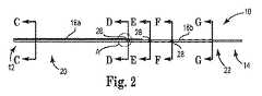
図1および図2は、本発明の、リード線本体プリフォーム10、すなわち予めモールド成形された基部をそれぞれ示す斜視図および側面断面図である。プリフォーム10は、マルチルーメンの医療用リード線の一部を形成する。リード線は、リード線本体、コイル導体、複数の導線および複数の電極を含む。リード線本体は、基端部と先端部を含む可撓性を備えた管状体であり、コイル導体ルーメン、並びに基端部と先端部との間を延びる複数の導線ルーメンを形成する。リード線本体は、リード線の組み立てに好適な任意の可撓性および生体適合性を備えた材料から形成される。様々な実施例において、リード線は、可撓性を備え電気的に絶縁される材料から形成される。一実施例において、リード線本体の基端側の部分は、例えばポリウレタンから形成され、リード線本体の先端側の部分はプリフォーム10を使用して形成され、通常例えばシリコーンから形成される。様々な実施例において、リード線本体のそれぞれのセグメントはその意図した臨床・操作環境にリード本体特性を合わせるように異なる材料から形成される。 FIGS. 1 and 2 are a perspective view and a side sectional view, respectively, showing a lead wire body preform 10 of the present invention, that is, a pre-molded base. The preform 10 forms part of a multi-lumen medical lead. The lead wire includes a lead wire body, a coil conductor, a plurality of conductive wires, and a plurality of electrodes. The lead wire body is a flexible tubular body including a proximal end portion and a distal end portion, and forms a coil conductor lumen and a plurality of conductive wire lumens extending between the proximal end portion and the distal end portion. The lead body is formed from any flexible and biocompatible material suitable for lead assembly. In various embodiments, the lead is formed from a material that is flexible and electrically insulated. In one embodiment, the proximal end portion of the lead wire body is formed from polyurethane, for example, and the distal end portion of the lead wire body is formed using the
本発明のプリフォーム10は、リード線本体の製造性を促進する特別な設計の特徴を含む。一実施例において、プリフォーム10はシリコーンから形成される。他の材料も考えられるが、好適なシリコーンの例は液体シリコーンゴム(LSR)である。例示的な設計の特徴は、その先端側の部分においてコイル導体と環境との間の僅かな壁厚が増加するプリフォーム10の基端側の部分と先端側の部分との間の偏心的なコイル導体ルーメンと、プリフォームの基端側の部分において導体を含み保護するポリウレタンとシリコーンとの移行領域と、プリフォーム10上への電極の配線を促進するように設計される溝と、オーバーモールド成形においてプリフォーム10の移動を防止すべくリード線本体の外径まで、または外径を超えて延びる突出部とを含む。 The
図1および2は、リード線本体への取り付け前、且つオーバーモールド成形される前のプリフォーム10を示す。プリフォーム10は、基端部12および先端部14を含む。プリフォームは、プリフォーム10の基端部12から先端部14に向かって変化する外径(OD)を更に有する。外径は、通常基端部12から先端部14に向かって径が減少し、また、外径は、プリフォーム10の長手方向に沿った位置にて徐々に低減または縮小される。外径の寸法および形状の両者は、基端部12から先端部14に向かって変化する。これらの変化により、電極は、プリフォーム10のシリコーンを低減して変形することによるリード線の製造において、先端部14からプリフォーム10の長手方向に沿った異なる位置までプリフォーム10上を基端側に摺動自在である。プリフォーム10の外径の形状は、プリフォーム10の長手方向に沿った所定の位置に応じて円形または非円形である。プリフォーム10の少なくとも1つの非対称領域は、非円形の外形を有する断面を有する。 1 and 2 show the
一実施例において、プリフォーム10は長さ約4インチ(10.16センチメートル(cm))である。プリフォームの長さは、電極が配置されることを要求される、リード線の先端部からの距離に依存する。従って、4インチ(10.16cm)以外の長さも考えられる。 In one embodiment, the
図示のように、プリフォーム10は、導体を収容するためのコイル導体ルーメン16、第1の導線ルーメン18a、第2の導線ルーメン18b、および第3の導線ルーメン18c(導線ルーメン18a乃至18cを、総称して「導線ルーメン18」と呼ぶ)を更に備える。コイル導体ルーメン16aの第1の部分は、プリフォーム10の基端側の部分20を通過して延び、コイル導体ルーメン16bの第2の部分は、プリフォーム10の先端側の部分22を通過して延びる。一実施例において、コイル導体ルーメン16aの第1の部分の径は約0.035インチ(0.889ミリメートル(mm))であり、コイル導体ルーメン16bの第2の部分の径は約0.028インチ(0.711mm)である。図示の二重部分コイル導体ルーメン16は、その長手方向に沿ってその径が低減または縮小するコイル導体を収容する。このような低減部を含まない他のコイル導体も、ここに開示されるプリフォーム10に収容される。しかしながら、コイル導体ルーメンの他の構成も考えられる(例えばその長手方向に沿って1つの径あるいは2つ以上の異なる径を有するコイル導体ルーメン)。 As shown, the
プリフォーム10は3つの導線ルーメンを含むものとして上述し図示したが、プリフォーム10は本発明の意図した範囲から逸脱することなく任意の数の導線ルーメンを含んでもよい。一実施例において、導線ルーメン18a乃至18cの各々の径は、約0.0105インチ(0.267mm)である。 Although the
図3は、図2のプリフォーム10のAにおける断面を示す拡大図である。図3にて視認されるように、プリフォーム10の基端側の部分20および先端側の部分22におけるコイル導体ルーメン16の第1の部分16aおよび第2の部分16bは、それぞれ相互に対して偏心する。偏心とは、例えば2つのルーメンが同じ中央部を有さないことを意味するか、これに代えて、ルーメン中央部が相互に離間することを意味する。偏心的なコイル導体ルーメン16aおよび16bにより、所定の外径を導体間の最小ウェブ厚、および導体と環境との間の最小壁厚に保持する。特に、偏心的なコイル導体ルーメンの設計により、プリフォーム10の外径およびこれにより得られるリード線本体の外径を小さく保持することができ、コイル導体ルーメン16と外径との間の僅かな壁の幅が増加する。一実施例において、コイル導体ルーメン16aおよび16bが同心であるというよりむしろ偏心的である場合に、僅かな壁は約0.004インチ(0.102mm)分増加する。 FIG. 3 is an enlarged view showing a cross section at A of the
プリフォーム10の機能のうちの1つは、電気的に導体を絶縁し、導体を変形可能とすることにある。偏心的なコイル導体ルーメン設計により付加的に絶縁されることによって、導体間の電気的絶縁を保持することが補助される。導体ルーメン16および18と外径との間の最小の壁厚は、電気的に導体を絶縁することに十分な量のシリコーンとなるように決定される。一実施例において、プリフォーム10は、約0.004インチ(0.102mm)の最小の壁厚を有する。付加的に、コイル導体ルーメン16と環境との間の壁の厚みが増加することにより、リード線本体はより堅固にして且つ長寿命となる。壁幅を増加させることにより、プリフォーム10に導体および電極を配線する工程等の後続する製造工程における損傷の傾向が低減される。 One of the functions of the
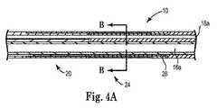
図4Aは図1に示すプリフォーム10の移行領域24におけるプリフォーム10を示す側面断面図である。図4Bは、図4Aに示すプリフォーム10の線B−Bにおける断面図である。移行領域24は、リード線本体の基端側の部分と先端側の部分との間の移行部近傍の、プリフォーム10の基端部12に配置される。リード線本体の基端側の部分および先端側の部分は、個別に形成され、且つ異なる材料から形成される。例えば、リード線本体の基端部は、ポリウレタンから押し出し形成され、リード線本体の先端部は本発明による方法を使用して形成され、シリコーンから形成される。実施例において、シリコーンは液体シリコーンゴム(LSR)である。従って、本発明によるプリフォーム10は、プリフォームの基端部12に、あるいは基端部12の近傍に、ポリウレタン53(外側層)およびシリコーン(後述するマルチルーメン・タブ26を形成する)、並びにポリウレタンとシリコーンとの間に配置される接着剤52から形成される移行領域24を含み、これにより、図1に示すようにリード線本体の基端側の部分と先端側の部分との間に、リード線本体の移行部の材料として導体が設けられる。移行領域24は、リード線本体内に導体およびコイル導体ルーメン16aを含み、これらを環境から保護する。 4A is a side sectional view showing the
移行領域24を形成するために、マルチルーメン・タブ26はプリフォーム10の基端側の部分20に予め形成され、ポリウレタンおよびシリコーンが固定領域接着剤充填物を使用して連結される。コイル導体ルーメン16aの周囲、且つプリフォーム10内のコイル導体ルーメン16aと導線ルーメン18a乃至18cとの間にシリコーンを設けることにより、曲げ疲労強度が補助される。図4Bに視認されるように、シリコーン26は、プリフォーム10の基端側の部分20においてコイル導体ルーメン16全体の周囲に、且つ導線ルーメン18a乃至18c全ての周囲に設けられる。 To form the
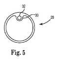
図5は、本発明のプリフォーム10から得られるマルチルーメンの医療用リード線の電極28を示す正面図である。電極28は、電極28が組み込まれるリード線本体の周囲の全てまたは少なくとも一部を包囲するように暴露された導電面を形成するリングの、またはリング状の電極である。通常、電極28は、内径、外径、および内径から延びる突出部30を有する。ルーメン32は突出部30内を通して延び、導線を通過させる寸法に形成される。一実施例において、マルチルーメンの医療用リード線は3つの電極を含むが、他の数の電極も考えられる。一実施例において、電極28はそれぞれ約0.059インチ(1.50mm)の内径を有する。 FIG. 5 is a front view showing a multi-lumen
図6Aは、電極28の基端側の図2に示すプリフォーム10の線C−Cにおける断面図である。線C−Cにおいて、プリフォーム10は、円形状を有し、コイル導体ルーメン16a、第1の導線ルーメン18a、第2の導線ルーメン18b、および第3の導線ルーメン18cを含む。図6Aにおいて視認されるように、導線ルーメン18は、プリフォーム10のコイル導体ルーメン16の上方に配置される。しかしながら、導体ルーメンの他の構成も考えられる。図示の一実施例の断面図において、シリコーンは、導体ルーメン16および18を形成する中空部を除いた断面を有する。 6A is a cross-sectional view of the
図5に示すように、実施において、第1の電極28は、第1の電極28の突出部30内のルーメン32が第1の導線ルーメン18aと並ぶように、プリフォーム10を覆って配線される。同様に、第2および第3の電極28は、各電極の突出部30内のルーメン32が第2および第3の導線ルーメン18bおよび18cとそれぞれ並ぶように、第1の電極の基端側にプリフォーム10を覆って配線される。 As shown in FIG. 5, in practice, the
図6B、図6C、および図6Dは、プリフォーム10の図2に示す線D−D、線E−Eおよび線F−Fにおける断面図である。図6Bは、プリフォーム10の基端部12に最も近接している電極28である第1の電極28の位置におけるプリフォーム10を示す断面図である。図6Cに示すように、線D−Dの先端側において、第1の溝34は、線D−Dの基端側に設けられるプリフォーム10の円形状の外形から区分されることにより得られ、設けられる。図6Cに示すように、第1の溝34は、第1の導線ルーメン18aによって覆われる領域と一致するかこの領域を占める領域を形成する。コイル導体ルーメン16、並びに第2および第3の導線ルーメン18bおよび18cが、プリフォーム10の周囲内になお形成される。図6Cに示すように、第1の溝34により、第1の電極28は、第1の電極28の突出部30がプリフォーム10を実質的に変形または圧縮することなく、線D−Dにおける位置までプリフォーム10に沿って摺動自在である。電極28および導線がプリフォーム10の先端部14からプリフォーム10の基端部12に向かって配線されるため、線D−Dにおいてプリフォーム10は1つの溝をのみ含む必要がある。第1の電極28は、図6Cに示すように、第1の電極28の突出部30が第1の溝34と並ぶようにプリフォーム10上に配線される。この位置において、第1の電極28の突出部30内のルーメン32は、プリフォーム10の第1の導線ルーメン18aと同一線上にある。 6B, 6C, and 6D are cross-sectional views of the
図6Cは、プリフォーム10に沿った第2の電極28の位置におけるプリフォーム10を示す断面図である。線E−Eにおいて、プリフォーム10は第1の溝34、および第2の溝36(図6Dに示す溝36)の両者を含む。図6Dに示す第2の溝36は、第2の導線ルーメン18bによって覆われる領域と一致するか、この領域を占める形状に形成される。コイル導体ルーメン16および第3の導線ルーメン18cは、線E−Eに、あるいは線E−Eの基端側に設けられるプリフォーム10の周囲内になお形成される。第2の電極28がプリフォーム10に沿って第1の電極28より先端側に配置されるため、また、電極28および導線がプリフォーム10の先端部14からプリフォーム10の基端部12に向かって配線されるため、線E−Eより先端側のプリフォーム10は、線D−Dと線E−Eとの間のプリフォーム10より少ない材料を含む。図6Dの第2の溝36により、第2の電極28は、第2の電極28の突出部30内のルーメン32がプリフォーム10の第2の導線ルーメン18bと同一線上にあるように線E−Eにてプリフォーム10に配置可能である。図示の実施例において、第1の導線ルーメン18aは、線E−Eまで先端側に延びない。図示の第1の導線ルーメン18aは、第1の電極28の位置にて、あるいは位置のちょうど先端側にて終端する。 FIG. 6C is a cross-sectional view showing the
図6Dは、プリフォーム10に沿った第3の電極28の位置におけるプリフォーム10を示す断面図である。線F−Fにおいて、プリフォーム10は、第1の溝34、第2の溝36、および第3の溝38(図6Eに点線を用いて示す溝38)を含む。図6Eに示す第3の溝38は、第3の導線ルーメン18cによって覆われる領域と一致するか対応する形状に形成され、更に第1の溝34および第2の溝36によって占められるものではないコイル導体ルーメン16全体の残りの部分を包囲して延びる。第3の電極28がプリフォーム10に沿って2つの第1の電極28より先端側に配置されるため、且つ電極28および導線がプリフォーム10の先端部14からプリフォーム10の基端部12に向かって配線されるため、線F−Fより先端側のプリフォーム10は、線E−Eと線F−Fとの間のプリフォーム10より少ない材料を含む。図6Eに示す第3の溝38により、第3の電極28は、第3の電極28の突出部30内のルーメン32がプリフォーム10の第3の導線ルーメン18cと同一線上にあるように線F−Fにてプリフォーム10に配置可能である。図示の実施例において、第2の導線ルーメン18bは、線F−Fまで先端側に延びない。図示の第2の導線ルーメン18bは、第2の電極28の位置にて、あるいは位置よりちょうど先端側にて終端する。 FIG. 6D is a cross-sectional view showing the
図6Eは、プリフォーム10に沿った第3の電極28の先端側におけるプリフォーム10を示す断面図である。線G−Gにおいて、プリフォーム10は略円形状を有し、コイル導体ルーメン16をのみ形成する。図示の実施例において、第3の導線ルーメン18cは、線G−Gまで先端側に延びない。第3の導線ルーメン18cは、第3の電極28の位置にて、あるいは位置のちょうど先端側にて終端する。図6Eに、第1の溝34、第2の溝36、および第3の溝38が全て例示の目的のためにのみ点線を用いて示される。3つの溝全ての領域は、実際残りのプリフォーム10の周囲の中空の空間であり、コイル導体ルーメン16bを形成または包囲するシリコーンの円形状部分を形成する。 FIG. 6E is a cross-sectional view showing the
図6A乃至6Eにて視認されるように、プリフォーム10は、線C−Cにて、すなわち電極28のいずれもの基端側の、プリフォーム10の基端部12の最も近傍の断面にて、ほとんどの材料を含む。プリフォーム10の基端部12から先端部14に向かって移動するにつれ、付加的なシリコーンは各電極位置(および電極位置の先端側)にてプリフォーム10の外径から取り払われるか設けられないため、プリフォーム10の外径は非円形である。プリフォーム10の材料は、プリフォーム10の先端部14が線G−Gにおいて、プリフォーム10の線C−Cにおける外径より小さな外径を有する中空の円形状に形成されるように、プリフォーム10の基端部12から先端部14に向かって低減される。 As can be seen in FIGS. 6A to 6E, the
電極28および導体がプリフォーム10上に配線されると、略円形の外径を有するリード線本体を形成すべく、液体シリコーンゴムのようなポリマがプリフォーム10上にオーバーモールド成形される。従って、プリフォーム10は、導体ルーメン16および18を全て包囲する十分な量の絶縁体を含むが、プリフォーム10の長手方向に沿って材料が取り払われることにより、電極28は、プリフォーム10を延ばしたり圧縮したりすることなく所定の位置に摺動自在である。図1を再び参照して、上述したように、プリフォーム10を覆うような内側のオーバーモールド成形は、プリフォーム10に沿った所望の位置に電極28を位置決めまたは保持することに、且つ更にリード線本体の先端側の部分22に所望の外形を形成することに使用可能である。オーバーモールド成形は、射出成形によるプレスにおいて、液体シリコーンゴムのようなポリマを使用することに依存する。この工程は、新しく付加されるポリマを硬化するために、プリフォーム10に対して加熱および加圧の両者を行う。 When the
関連する電極とともにプリフォームをオーバーモールド成形するために、電極を備えたプリフォームはモールド・キャビティに載置される。一実施例において、モールド型枠は長尺状をなす円筒形状を有する。プリフォーム10の周囲、およびプリフォーム10とモールド・キャビティの内側表面との間にポリマが注入されるように、モールド・キャビティにおいてプリフォーム10を心出しすることが望ましい。プリフォーム10を心出しすることにより、複製可能な壁厚および予測可能なコイル導体ルーメン位置を備えた完成品のリード線本体の生産が可能となる。 In order to overmold the preform with the associated electrode, the preform with the electrode is placed in a mold cavity. In one embodiment, the mold form has an elongated cylindrical shape. It is desirable to center the
プリフォームを心出しすべく、プリフォーム10は、プリフォーム10の長手方向に沿って複数の突出部40を含み、これらの突出部40はモールド・キャビティの内側表面と接触し、モールド・キャビティの所望の位置にプリフォーム10を保持する。図1に一実施例における突出部(40)を示す。図7は突出部40を示す拡大図である。突出部40はオーバーモールド成形される所望の完成品のリード線本体の外径に略等しい外径を有するように、すなわち完成品のリード線本体の最も外側の径まで径方向に外方に向かって延びる長さを有するように製造される。突出部40は、使用されるモールド型枠内にプリフォーム10を安置するとともに電極配線工程を妨害しないようにプリフォーム10の径の周囲に、あるいは外周面の周囲に配置される。突出部40は矩形の形状を有し、プリフォーム10に沿って長手方向に延びる。しかしながら、突出部40の他の形状および構成も考えられる。 To center the preform, the
突出部40は、プリフォーム10の心出しを保持すべく(モールド・キャビティの内側表面に対する)圧縮を使用する。プリフォーム10がシリコーンによりオーバーモールド成形された後に、同じシリコーンから形成されてもよい突出部40はリード線の先端部の部分に実質的に消失してもよい。 The
図8は、実施例において、プリフォーム10をオーバーモールド成形すべく、突出部40に代えて、モールド・キャビティにプリフォームを心出しすることに使用される心出し突起60および錠剤形の突起70を含むプリフォーム10を示す。心出し突起60は、プリフォーム10の少なくとも一部の周囲に周方向に延びる。すなわち、心出し突起60は、プリフォーム10から径方向に外方に向かって延びる。突出部40と同様に、心出し突起60は、オーバーモールド成形のためにプリフォーム10を所定の位置に保持すべく、モールド・キャビティの内側表面に対する圧縮を使用する。心出し突起60は、単独にて、あるいは錠剤形のこぶ70と組み合わせて使用される。 FIG. 8 shows, in the embodiment, a centering
オーバーモールド成形のために、錠剤形の突起70は、モールド・キャビティの所定の位置にプリフォーム10を保持すべく圧縮ではなく張引を使用してもよい。錠剤形の突起70は、相互に離間してプリフォーム10の残りの部分に取り付けられても残りの部分から延びてもよい。錠剤形の突起70は、錠剤形の突起70を所定の位置に保持すべく調整されるモールド・キャビティの一部(図示しない)に対応するように構成される形状および寸法を有する。 For overmolding, the tablet-shaped
オーバーモールド成形において、錠剤形の突起70は、モールド・キャビティの外部に配置される。ここで使用されるモールド・キャビティは、錠剤形の突起70の少なくとも一部が通過して延びる開口部を含む。これに代えて、モールド・キャビティは、錠剤形の突起70を保持するように設計されてもよい。オーバーモールド成形後に、錠剤形の突起70は、リード線本体の残りから取り払われる。錠剤形の突起70は、単独にて、あるいは心出し突起60と組み合わせて使用される。 In overmolding, the tablet-shaped
図9Aは、プリフォーム10の線I−Iにおける断面図である。断面形状は、突出部40が代わりに使用される場合に、通常図1と同じ形状である。図9Bは、心出し突起60がプリフォーム10の略円形状の中央部の周囲または外周面の周囲の様々な位置に配置され、プリフォーム10から径方向に外方に向かって延びることを示す。心出し突起60の位置は、電極28が先端部からプリフォーム10上に配線されるように選択される。 FIG. 9A is a cross-sectional view of the
図9Bは、一実施例における錠剤形の突起70を更に示す。錠剤形の突起70は、プリフォーム10の一部として形成される。図示の実施例において、錠剤形の突起70の錠剤形の部分72をプリフォーム10の中央部の略円形状の部分11に連結する連結領域71が設けられる。オーバーモールド成形の後に、錠剤形の突起70は、各連結領域71を分離することにより、リード線本体の残りの部分から取り払われる。錠剤形の突起70は、プリフォーム10の残りの部分から構成されるシリコーン、あるいは他の好適な材料を含んでもよい。 FIG. 9B further illustrates a tablet-shaped
図9Cは、別例において心出しハブ60が使用されるプリフォーム10を示す線K−Kにおける断面図である。図示の実施例において、1つの電極28が、断面K−Kの基端側のプリフォームに配置される。従って、図9Cは、電極28が先端部から配線されるように円形の断面の中空部、すなわち溝34を含む。付加的な断面図には示さないが、図6C、図6D、および図6Eに示す溝36および38が、図8のプリフォーム10に2つの付加的な電極28を配線すべく更に設けられる。 FIG. 9C is a cross-sectional view along line KK showing the
オーバーモールド成形において、リード線本体の基端側の部分は、リード線本体を形成すべくプリフォーム10に更に連結される。オーバーモールド成形により、プリフォーム10の非対称領域は略円形になる。 In overmolding, the proximal end portion of the lead wire body is further coupled to the
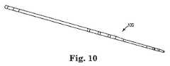
図10は、本発明のプリフォーム10を含む完全に組み立てられたリード線100を示す。プリフォーム10がリード線100を形成すべくオーバーモールド成形されると、プリフォーム10は好適に個別に視認不能である。 FIG. 10 shows a fully assembled
本発明の予めモールド成形された基部、およびリード線の製造方法により、リード線の製造性が促進される。予めモールド成形された基部、すなわちプリフォームは、僅かな壁厚を増加させ、予めモールド成形された基部上に電極を配線することを促進し、オーバーモールド成形において予めモールド成形された基部の移動を防止する。 The premolded base and lead wire manufacturing method of the present invention promotes lead wire manufacturability. The pre-molded base, i.e. the preform, increases the slight wall thickness, facilitates wiring of the electrode on the pre-molded base, and moves the pre-molded base in overmolding. To prevent.
様々な変形および付加が、本発明の範囲から逸脱することなく上述した実施例に応用可能である。例えば、上述した実施例は、所定の特徴を示すが、本発明の範囲は上述した特徴の全てを含んでいるとは限らない特徴および実施例の異なる組み合わせを有する実施例も含む。従って、本発明の範囲は、請求の範囲内に相当する別例、変形および変化の全てと、その均等物の全てを包含するように意図される。 Various modifications and additions can be applied to the above-described embodiments without departing from the scope of the present invention. For example, although the embodiments described above exhibit certain features, the scope of the invention also includes embodiments having different combinations of features and embodiments that do not necessarily include all of the features described above. Accordingly, the scope of the invention is intended to embrace all such alternatives, modifications and variations that fall within the scope of the claims and all equivalents thereof.
付記1. マルチルーメンリード線に電極を配線する方法であって、Appendix 1. A method of wiring an electrode to a multi-lumen lead wire,
リード線本体の先端部の少なくとも一部分のプリフォームを準備する工程と、 Preparing a preform for at least a portion of the tip of the lead wire body;
前記プリフォームの先端部の長手方向に沿って複数の電極を位置決めする工程と、 Positioning a plurality of electrodes along the longitudinal direction of the tip of the preform;
前記プリフォームを覆うようにシリコーンの層を堆積させる工程とを含み、 Depositing a layer of silicone over the preform;
前記プリフォームは同プリフォーム内に少なくとも1つの溝を含むことを特徴とするマルチルーメンリード線に電極を配線する方法。 A method for wiring electrodes to a multi-lumen lead wire, wherein the preform includes at least one groove in the preform.
付記2. 前記プリフォームは異なる寸法の3つの溝を含むことを特徴とする付記1に記載の方法。Appendix 2. The method of claim 1, wherein the preform includes three grooves of different dimensions.
付記3. 前記プリフォームは同プリフォームの長手方向に沿って複数の突出部を含むことを特徴とする付記1または2に記載の方法。Appendix 3. The method according to claim 1 or 2, wherein the preform includes a plurality of protrusions along a longitudinal direction of the preform.
付記4. 前記突出部のうちの少なくともいくつかは、リード線本体部分の外径と等しい長さまで径方向外方に延びることを特徴とする付記3に記載の方法。Appendix 4. The method of claim 3, wherein at least some of the protrusions extend radially outward to a length equal to the outer diameter of the lead body portion.
付記5. 前記突出部のうちの少なくともいくつかは、リード線本体部分の最も外側の径を超えて径方向に外方に延びることを特徴とする付記3に記載の方法。Appendix 5. The method of claim 3, wherein at least some of the protrusions extend radially outward beyond the outermost diameter of the lead body portion.
付記6. 前記プリフォームはポリウレタンからシリコーンへと変化する移行部を含むことを特徴とする付記2乃至5のうちいずれか一つに記載の方法。Appendix 6. 6. The method according to any one of appendices 2 to 5, wherein the preform includes a transition portion that changes from polyurethane to silicone.
Claims (13)
Translated fromJapanese基端部と、先端部と、同基端部および先端部の間を延びる少なくとも1つのルーメンとを備えるリード線本体プリフォームをモールド成形する工程であって、該プリフォームの少なくとも1つの非対称領域は非円形の外形を有する断面を有する、モールド成形する工程と、
複数の電極が前記プリフォームの長手方向に沿ってそれぞれ対応する複数の異なる位置に配置されるように前記プリフォームに前記複数の電極を摺動させる工程であって、前記プリフォームの外径は、前記複数の異なる位置のそれぞれにおいて異なる、前記複数の電極を摺動させる工程と、
リード線本体部分を形成すべくポリマにより前記プリフォームをオーバーモールド成形する工程とを含み、このオーバーモールド成形工程により、前記非対称領域は円形になることを特徴とする医療用リード線の製造方法。A method of manufacturing a medical lead wire,
Molding a lead body preform comprising a proximal end, a distal end, and at least one lumen extending between the proximal end and the distal end,wherein the at least one asymmetric region of the preform Has a cross-section with a non-circular profile, and molding,
A processin which a plurality of electrodes Ruslidethe plurality of electrodes in the preformto be placed in different positions corresponding respectively along the longitudinal direction of thepreform,the outer diameter of the preform Sliding the plurality of electrodes different at each of the plurality of different positions ;
And a step of over-moldingthe preform by the polymer to form a lead body portion, by the over-molding process, the asymmetric region manufacturing method of a medical lead, characterized by comprising a circular.
リード線本体部分の少なくとも一部分の予めモールド成形された基部を準備する工程であって、前記予めモールド成形された基部の外径は該予めモールド成形された基部の長手方向に沿って変化する、前記予めモールド成形された基部を準備する工程と、
複数の電極が前記長手方向に沿ってそれぞれ対応する複数の異なる位置に配置されるように、且つ前記予めモールド成形された基部を覆うように前記複数の電極を摺動させる工程であって、前記予めモールド成形された基部の外径は、前記複数の異なる位置のそれぞれにおいて異なる、前記複数の電極を摺動させる工程と、
円滑な外径を有するリード線本体部分を形成すべく前記予めモールド成形された基部にポリマを堆積させる工程とを含むことを特徴とするマルチルーメンリード線の製造方法。A multi-lumen lead wire manufacturing method,
Comprising the steps of providing at least pre-molded shaped base of a portion of the lead body portion, an outer diameter of the pre-molded base varies along the longitudinal direction of the base that isthe pre-molded,the Preparing a pre-molded base;
As the plurality of electrodes are arranged in a plurality of different positions corresponding respectively along the longitudinal direction, andsaidmethod comprising Ruslidethe plurality of electrodes so as to cover the pre-mold shapedbase, The outer diameter of the pre-molded base is different at each of the plurality of different positions, sliding the plurality of electrodes ; and
Method for producing a multi-lumen lead, characterized in that it comprises depositing a polymer onthe base that has been previously molded to form the lead body portion having a smooth outer diameter.
Applications Claiming Priority (5)
| Application Number | Priority Date | Filing Date | Title |
|---|---|---|---|
| US29110209P | 2009-12-30 | 2009-12-30 | |
| US61/291,102 | 2009-12-30 | ||
| US12/949,638US8728562B2 (en) | 2009-12-30 | 2010-11-18 | Implantable leads with a unitary silicone component |
| US12/949,638 | 2010-11-18 | ||
| PCT/US2010/058982WO2011081778A1 (en) | 2009-12-30 | 2010-12-03 | Implantable leads with a unitary silicone component |
Publications (2)
| Publication Number | Publication Date |
|---|---|
| JP2013516228A JP2013516228A (en) | 2013-05-13 |
| JP5540113B2true JP5540113B2 (en) | 2014-07-02 |
Family
ID=44246936
Family Applications (1)
| Application Number | Title | Priority Date | Filing Date |
|---|---|---|---|
| JP2012547090AExpired - Fee RelatedJP5540113B2 (en) | 2009-12-30 | 2010-12-03 | Method of manufacturing an implantable lead with an integral silicone part |
Country Status (3)
| Country | Link |
|---|---|
| EP (1) | EP2519307B1 (en) |
| JP (1) | JP5540113B2 (en) |
| WO (1) | WO2011081778A1 (en) |
Families Citing this family (1)
| Publication number | Priority date | Publication date | Assignee | Title |
|---|---|---|---|---|
| US11458300B2 (en) | 2018-12-28 | 2022-10-04 | Heraeus Medical Components Llc | Overmolded segmented electrode |
Family Cites Families (10)
| Publication number | Priority date | Publication date | Assignee | Title |
|---|---|---|---|---|
| JPH04208171A (en)* | 1990-08-10 | 1992-07-29 | Kunimori Kagaku:Kk | Manufacture of grip for golf club |
| EP0971767A2 (en)* | 1996-12-19 | 2000-01-19 | Medtronic, Inc. | Medical electrical lead |
| US5921933A (en)* | 1998-08-17 | 1999-07-13 | Medtronic, Inc. | Medical devices with echogenic coatings |
| US6240322B1 (en)* | 1998-11-04 | 2001-05-29 | Cardiac Pacemakers, Inc. | System and apparatus having low profile collapsible tines |
| JP2003056782A (en)* | 2001-08-09 | 2003-02-26 | Nissan Motor Co Ltd | Connection structure of resin connector and resin tube |
| US7234225B2 (en)* | 2003-09-22 | 2007-06-26 | St. Jude Medical, Atrial Fibrillation Division, Inc. | Method for manufacturing medical device having embedded traces and formed electrodes |
| US7221982B2 (en)* | 2004-07-12 | 2007-05-22 | Cardiac Pacemakers, Inc. | Apparatus and method of coating implantable leads |
| US7857809B2 (en)* | 2005-12-30 | 2010-12-28 | Biosense Webster, Inc. | Injection molded irrigated tip electrode and catheter having the same |
| US7917229B2 (en)* | 2006-08-31 | 2011-03-29 | Cardiac Pacemakers, Inc. | Lead assembly including a polymer interconnect and methods related thereto |
| US8849424B2 (en)* | 2008-03-25 | 2014-09-30 | Medtronic, Inc. | Integrated conductive sensor package having conductor bypass, distal electrode, distal adapter and custom molded overlay |
- 2010
- 2010-12-03JPJP2012547090Apatent/JP5540113B2/ennot_activeExpired - Fee Related
- 2010-12-03WOPCT/US2010/058982patent/WO2011081778A1/enactiveApplication Filing
- 2010-12-03EPEP10793371.5Apatent/EP2519307B1/ennot_activeNot-in-force
Also Published As
| Publication number | Publication date |
|---|---|
| EP2519307A1 (en) | 2012-11-07 |
| EP2519307B1 (en) | 2015-09-09 |
| JP2013516228A (en) | 2013-05-13 |
| WO2011081778A1 (en) | 2011-07-07 |
Similar Documents
| Publication | Publication Date | Title |
|---|---|---|
| US5303704A (en) | Medical electrical lead | |
| US8292828B2 (en) | Guide wire for a medical instrument | |
| US8728562B2 (en) | Implantable leads with a unitary silicone component | |
| US20130131642A1 (en) | Guidewire | |
| US9364662B2 (en) | Implantable lead having a lumen with a wear-resistant liner | |
| US20050027340A1 (en) | System and method for providing a medical lead body having dual conductor layers | |
| US20050027339A1 (en) | System and method for providing a medical lead body | |
| JP2017502731A (en) | Soft tip catheter | |
| JP2014520601A (en) | Intact ureteral access sheath | |
| KR102125109B1 (en) | Catheter | |
| US10888341B2 (en) | Balloon catheter | |
| JP2017527366A (en) | Irrigation ablation catheter and method for producing the same | |
| JPWO2019003425A1 (en) | catheter | |
| JP5540113B2 (en) | Method of manufacturing an implantable lead with an integral silicone part | |
| CN111265771B (en) | Electrical conductor and preparation method thereof and implantable biological electrode | |
| CN103143106B (en) | Wire | |
| US20200269010A1 (en) | Tensile-strength-enhancing tube for an implantable electrode lead or a catheter, electrode lead with a tensile-strength-enhancing tube, and catheter with a tensile-strength-enhancing tube | |
| JP7290264B2 (en) | CATHETER TUBE UNIT USED FOR ELECTRODE CATHETER AND MANUFACTURING METHOD THEREOF, CATHETER TUBE AND ELECTRODE CATHETER | |
| JP2019528958A5 (en) | ||
| JP2013093246A (en) | Multielectrode single-head plug and method of manufacturing the same | |
| US9461421B2 (en) | Catheter handle | |
| US9808614B2 (en) | Implantable curved shaping part for externally shaping an implantable electrode line or a catheter | |
| US11992673B2 (en) | Implantable medical devices and methods of manufacture | |
| EP3171931B1 (en) | Methods of shielding implantable medical leads and implantable medical lead extensions | |
| EP4226966A1 (en) | Implantable lead and method for manufacturing the implantable lead |
Legal Events
| Date | Code | Title | Description |
|---|---|---|---|
| A521 | Request for written amendment filed | Free format text:JAPANESE INTERMEDIATE CODE: A523 Effective date:20140217 | |
| TRDD | Decision of grant or rejection written | ||
| A01 | Written decision to grant a patent or to grant a registration (utility model) | Free format text:JAPANESE INTERMEDIATE CODE: A01 Effective date:20140422 | |
| R150 | Certificate of patent or registration of utility model | Ref document number:5540113 Country of ref document:JP Free format text:JAPANESE INTERMEDIATE CODE: R150 | |
| A61 | First payment of annual fees (during grant procedure) | Free format text:JAPANESE INTERMEDIATE CODE: A61 Effective date:20140501 | |
| R250 | Receipt of annual fees | Free format text:JAPANESE INTERMEDIATE CODE: R250 | |
| R250 | Receipt of annual fees | Free format text:JAPANESE INTERMEDIATE CODE: R250 | |
| R250 | Receipt of annual fees | Free format text:JAPANESE INTERMEDIATE CODE: R250 | |
| R250 | Receipt of annual fees | Free format text:JAPANESE INTERMEDIATE CODE: R250 | |
| LAPS | Cancellation because of no payment of annual fees |