JP5538467B2 - Lens unit, light irradiation unit and light irradiation device - Google Patents
Lens unit, light irradiation unit and light irradiation deviceDownload PDFInfo
- Publication number
- JP5538467B2 JP5538467B2JP2012078936AJP2012078936AJP5538467B2JP 5538467 B2JP5538467 B2JP 5538467B2JP 2012078936 AJP2012078936 AJP 2012078936AJP 2012078936 AJP2012078936 AJP 2012078936AJP 5538467 B2JP5538467 B2JP 5538467B2
- Authority
- JP
- Japan
- Prior art keywords
- lens
- light
- irradiation
- lenses
- optical axis
- Prior art date
- Legal status (The legal status is an assumption and is not a legal conclusion. Google has not performed a legal analysis and makes no representation as to the accuracy of the status listed.)
- Active
Links
Images


Classifications
- G—PHYSICS
- G02—OPTICS
- G02B—OPTICAL ELEMENTS, SYSTEMS OR APPARATUS
- G02B13/00—Optical objectives specially designed for the purposes specified below
- G02B13/001—Miniaturised objectives for electronic devices, e.g. portable telephones, webcams, PDAs, small digital cameras
- G02B13/0015—Miniaturised objectives for electronic devices, e.g. portable telephones, webcams, PDAs, small digital cameras characterised by the lens design
- G02B13/002—Miniaturised objectives for electronic devices, e.g. portable telephones, webcams, PDAs, small digital cameras characterised by the lens design having at least one aspherical surface
- G02B13/003—Miniaturised objectives for electronic devices, e.g. portable telephones, webcams, PDAs, small digital cameras characterised by the lens design having at least one aspherical surface having two lenses
- G—PHYSICS
- G02—OPTICS
- G02B—OPTICAL ELEMENTS, SYSTEMS OR APPARATUS
- G02B13/00—Optical objectives specially designed for the purposes specified below
- G02B13/14—Optical objectives specially designed for the purposes specified below for use with infrared or ultraviolet radiation
- G—PHYSICS
- G02—OPTICS
- G02B—OPTICAL ELEMENTS, SYSTEMS OR APPARATUS
- G02B19/00—Condensers, e.g. light collectors or similar non-imaging optics
- G02B19/0033—Condensers, e.g. light collectors or similar non-imaging optics characterised by the use
- G02B19/0047—Condensers, e.g. light collectors or similar non-imaging optics characterised by the use for use with a light source
- G—PHYSICS
- G02—OPTICS
- G02B—OPTICAL ELEMENTS, SYSTEMS OR APPARATUS
- G02B27/00—Optical systems or apparatus not provided for by any of the groups G02B1/00 - G02B26/00, G02B30/00
- G02B27/09—Beam shaping, e.g. changing the cross-sectional area, not otherwise provided for
- G02B27/0927—Systems for changing the beam intensity distribution, e.g. Gaussian to top-hat
- G—PHYSICS
- G03—PHOTOGRAPHY; CINEMATOGRAPHY; ANALOGOUS TECHNIQUES USING WAVES OTHER THAN OPTICAL WAVES; ELECTROGRAPHY; HOLOGRAPHY
- G03B—APPARATUS OR ARRANGEMENTS FOR TAKING PHOTOGRAPHS OR FOR PROJECTING OR VIEWING THEM; APPARATUS OR ARRANGEMENTS EMPLOYING ANALOGOUS TECHNIQUES USING WAVES OTHER THAN OPTICAL WAVES; ACCESSORIES THEREFOR
- G03B17/00—Details of cameras or camera bodies; Accessories therefor
- G03B17/02—Bodies
- G03B17/04—Bodies collapsible, foldable or extensible, e.g. book type
Landscapes
- Physics & Mathematics (AREA)
- General Physics & Mathematics (AREA)
- Optics & Photonics (AREA)
- Health & Medical Sciences (AREA)
- Toxicology (AREA)
- Non-Portable Lighting Devices Or Systems Thereof (AREA)
- Lens Barrels (AREA)
- Lenses (AREA)
- Heating, Cooling, Or Curing Plastics Or The Like In General (AREA)
Description
Translated fromJapaneseこの発明は、照射光の照度分布を細長のライン状に成形するレンズユニット並びに該レンズユニットを備えた光照射ユニット及び光照射装置に関する。 The present invention relates to a lens unit that molds an illuminance distribution of irradiated light into an elongated line, and a light irradiation unit and a light irradiation apparatus including the lens unit.
工業製品のコーティングや光学部品等の組み立て用接着剤として、紫外線硬化型樹脂が用いられている。紫外線硬化型樹脂は、流動性を有するモノマーやオリゴマーが紫外線(紫外光)を吸収して光重合反応を起こし、固体のポリマーに変化する樹脂である。そして、この紫外線硬化型樹脂を硬化させるための光源として紫外線照射装置(以下「UV照射装置」という。)が開発されている。 An ultraviolet curable resin is used as an adhesive for assembling industrial product coatings and optical parts. The ultraviolet curable resin is a resin that changes into a solid polymer by causing a photopolymerization reaction when a monomer or oligomer having fluidity absorbs ultraviolet rays (ultraviolet light). An ultraviolet irradiation device (hereinafter referred to as “UV irradiation device”) has been developed as a light source for curing the ultraviolet curable resin.
UV照射装置としては、高圧水銀ランプや水銀キセノンランプ等を光源とするランプ型照射装置が知られているが、近年、消費電力の削減や装置サイズのコンパクト化の要請から、紫外光を発光可能な発光ダイオード(LED)を光源とするUV照射装置が開発されている(例えば、特許文献1)。 As a UV irradiation device, a lamp type irradiation device using a high-pressure mercury lamp, a mercury xenon lamp, or the like as a light source is known. However, in recent years, UV light can be emitted due to a demand for reduction of power consumption and downsizing of the device A UV irradiation apparatus using a light emitting diode (LED) as a light source has been developed (for example, Patent Document 1).
特許文献1に開示されるUV照射装置は、照射ヘッド内に直列に配置された2枚の球面レンズを備えており、LED光をスポット状に集光する。このようなUV照射装置を使用して液晶パネルの張り合わせ工程のような大面積の接着を行う場合には、隣接する照射ヘッドのスポットの裾同士が重なり合うように複数の照射ヘッドを一列に並べて使用すると効率的に接着剤の硬化を行うことができる。しかしながら、特許文献1のUV照射装置は、球面レンズにより直交2方向に集光される為、照射光のスポットサイズが小さく、多数の照射ヘッドを並べなければならない。 The UV irradiation apparatus disclosed in
また、球面レンズをシリンドリカルレンズに替えることで、シリンドリカルレンズの焦線方向におけるビーム幅の長いライン状の照射光を得ることができるが、ライン方向(ビームの長径方向)において強度(照度)が均一な照射光を得るには、2枚のシリンドリカルレンズの焦線方向を高い精度で合わせる必要がある。従来、シリンドリカルレンズの焦線方向の調整は、複雑な光学的アライメントによって行われていた為、球面レンズからシリンドリカルレンズへの置き換えは、製造コストの大幅な増大を伴った。 In addition, by replacing the spherical lens with a cylindrical lens, it is possible to obtain line-shaped irradiation light with a long beam width in the focal line direction of the cylindrical lens, but the intensity (illuminance) is uniform in the line direction (the long axis direction of the beam). In order to obtain an appropriate irradiation light, it is necessary to align the focal direction of the two cylindrical lenses with high accuracy. Conventionally, adjustment of the focal direction of the cylindrical lens has been performed by complicated optical alignment, so that replacement of the spherical lens with the cylindrical lens has accompanied a significant increase in manufacturing cost.
また、ライン状の照射光を出射する照射ヘッドを複数並べて使用する場合には、照射ヘッドを並べる方向に照射光の長径方向を正確に揃える必要があるが、紫外光は不可視であるため、例えば蛍光板に照射光を当てながら照射ヘッドの向きを調整しなければならず、煩雑な調整作業を必要とした。 In addition, when using a plurality of irradiation heads that emit line-shaped irradiation light, it is necessary to accurately align the major axis direction of the irradiation light in the direction in which the irradiation heads are arranged, but since ultraviolet light is invisible, for example, The direction of the irradiation head had to be adjusted while irradiating the fluorescent plate with the irradiation light, requiring complicated adjustment work.
本発明は、上記の事情に鑑みてなされたものであり、組み立て及び設置が容易な、ライン状の均一な照度分布を有する照射光を出射するレンズユニット、光照射ユニット及び光照射装置を提供することを目的とする。 The present invention has been made in view of the above circumstances, and provides a lens unit, a light irradiation unit, and a light irradiation device that emit irradiation light having a uniform illumination distribution in a line shape that is easy to assemble and install. For the purpose.
上記目的を達成するため、本発明の実施形態に係るレンズユニットは、それぞれ第1面に凸レンズ面が形成されたシリンドリカルレンズである第1及び第2のレンズと、第1及び第2のレンズを、凸レンズ面同士が所定の距離を置いて対向し、且つ各光軸が一致するように保持する鏡筒と、を備え、鏡筒は、第1及び第2のレンズの焦線が光軸に垂直な第1の方向に向くように各レンズの凸レンズ面の先端部と嵌合し、各レンズの回転を規制すると共に各レンズを位置決めする中間鏡筒部を備え、中間鏡筒部の外周面には、光軸を通り、第1の方向又は光軸及び第1の方向に垂直な第2の方向に延びる直線上の少なくとも一箇所にマーカーが形成されていることを特徴とする。In order to achieve the above object, a lens unit according to an embodiment of the present invention includes a first lens and a second lens, which are cylindrical lenses each having a convex lens surface formed on a first surface, and a first lens and a second lens. , convex faces are opposed at a predetermined distance, and and a barrel for holding such that each optical axes coincide, the barrelisfocal line of the first and second lenses to the optical axis An intermediate lens barrel part thatfits with the tip of the convex lens surface of each lens so as to face the first vertical direction, regulates the rotation of each lens and positions each lens, and has an outer peripheral surface of the intermediate lens barrel part Is characterized in that a marker is formed in at least one place on a straight line that passes throughtheoptical axis andextendsin the firstdirection or the second directionperpendicular to theoptical axis and the first direction .
上記の構成によれば、中間鏡筒部の外周面に設けられたマーカーにより、レンズユニットの集光方向を正確に認識することができ、レンズユニットを設置する際の位置決めを正確且つ容易に行うことが可能になる。また、上記の構成によれば、光束が第1の方向(長径方向)に集光されない為、第1の方向のビーム幅を短くすることなく出射光の強度を高めることができる。また、上記の構成によれば、組み立て時に2枚のシリンドリカルレンズの焦線の向きを正確且つ容易に合わせることができる。According to said structure, the marker provided in the outer peripheral surface of the intermediate lens-barrel part can recognize the condensing direction of a lens unit correctly, and positioning at the time of installing a lens unit is performed correctly and easily. It becomes possible. Moreover, according to said structure, since a light beam is not condensed in a1st direction (major axis direction), the intensity | strength of emitted light can be raised, without shortening the beam width of a1st direction. Moreover, according to said structure, the direction of the focal line of two cylindrical lenses can be match | combined correctly and easily at the time of an assembly.
中間鏡筒部が、中間鏡筒部の内周面から中心軸に向かって突出する突出部を有し、突出部には、光軸を通り第1の方向に延びる直線上に、光軸を挟んで一対の切欠部が設けられており、第1及び第2のレンズの凸レンズ面の先端部がそれぞれ一対の切欠部に嵌り込むように構成してもよい。The intermediate lens barrel portion has a protruding portion that protrudes from the inner peripheral surface of the intermediate lens barrel portion toward the central axis, and the protruding portion has an optical axis on a straight line that extends in thefirst direction through the optical axis. a pair of notched portions are provided to sandwich the tip portion of the convex lens surface of the first and second lens may be respectivelyconfigured to fit into a pair of cutout portions.
この構成によれば、各レンズの凸レンズ面を中間鏡筒部の突出部に押し付けながら中心軸の周りに回転させるだけの簡単な作業により、凸レンズ面の先端部が切欠部に嵌り込んで、各レンズの方向を高精度に位置決めすることができる。 According to this configuration, the tip portion of the convex lens surface is fitted into the notch portion by a simple operation of rotating around the central axis while pressing the convex lens surface of each lens against the protruding portion of the intermediate lens barrel portion. The direction of the lens can be positioned with high accuracy.
第1及び第2のレンズが、それぞれ円柱状の側面を有し、中間鏡筒部が、第1及び第2のレンズの外径よりもわずかに内径が広い内周面を有する略円筒状であり、第1及び第2のレンズの凸レンズ面側の少なくとも一部をそれぞれ該中間鏡筒部の中空部内に収容し、突出部が、第1及び第2のレンズの外径よりも狭い内径を有する略円環状に形成されている構成としてもよい。 Each of the first and second lenses has a cylindrical side surface, and the intermediate lens barrel has a substantially cylindrical shape having an inner peripheral surface slightly wider in inner diameter than the outer diameter of the first and second lenses. Yes, at least a part of the first lens and the second lens on the convex lens surface side are respectively accommodated in the hollow portion of the intermediate lens barrel, and the protrusion has an inner diameter narrower than the outer diameter of the first and second lenses. It is good also as a structure currently formed in the substantially annular shape which has.
また、中間鏡筒部の内周面には、光軸を挟んだ第1の方向の両側に、光軸方向の一端より突出部を横断して光軸方向に延びる一対の溝が形成されており、該一対の溝を形成することにより、突出部に一対の切欠部が設けられた構成としてもよい。In addition, a pair of grooves extending in the optical axis direction across one end of the optical axis direction from one end in the optical axis direction are formed on the inner peripheral surface of the intermediate barrel portion on both sides in thefirst direction across the optical axis. In addition, by forming the pair of grooves, the protrusion may be provided with a pair of notches.
上記の構成によれば、切欠部を容易に形成することができる。 According to said structure, a notch part can be formed easily.
また、マーカーが、中間鏡筒部の軸方向に延びるマーカー溝である構成としてもよい。 The marker may be a marker groove extending in the axial direction of the intermediate lens barrel.
上記の構成によれば、例えばマシニングセンタを使用して中間鏡筒部を加工することにより、高い相対位置精度で切欠部とマーカーを形成することができると共に、視認性の良好なマーカーが実現する。 According to the above configuration, for example, by processing the intermediate lens barrel portion using a machining center, the notch portion and the marker can be formed with high relative positional accuracy, and a highly visible marker is realized.
また、第1及び第2のシリンドリカルレンズの外径が同一である構成としてもよい。 Further, the first and second cylindrical lenses may have the same outer diameter.
上記の構成によれば、部品の種類が少なく、また少ない工程で中間鏡筒部を加工することができる為、レンズユニットを低コストで製造することが可能になる。 According to the above configuration, the number of types of parts is small, and the intermediate lens barrel can be processed with a small number of processes, so that the lens unit can be manufactured at a low cost.
本発明の実施形態に係る光照射ユニットは、光源ユニットと、光源ユニットが出射した光束を第2の方向に集光する、上記のレンズユニットと、を備え、第1の方向に長いライン状の照射領域を有する照射光を生成する。A light irradiation unit according to an embodiment of the present invention includes a light source unit and the lens unit that collects a light beam emitted from the light source unit in asecond direction, and has a linear shape that is long in thefirst direction. Irradiation light having an irradiation region is generated.
また、光源ユニットが、二次元配列された複数のLED素子を備えた構成としてもよい。また、光源ユニットが、第1及び第2の方向にそれぞれ平行な二辺を有する矩形状の発光面を備えた構成としてもよい。 Moreover, it is good also as a structure with which the light source unit was provided with several LED element arranged in two dimensions. In addition, the light source unit may include a rectangular light emitting surface having two sides parallel to each of the first and second directions.
上記の構成によれば、シリンドリカルレンズにより一方向のみに集光しても、十分に高い強度の照射光を得ることができる。 According to said structure, even if it condenses only to one direction with a cylindrical lens, sufficiently high intensity | strength irradiation light can be obtained.
本発明の実施形態に係る光照射装置は、上記の光照射ユニットを複数備え、複数の光照射ユニットは、光軸を互いに平行にして第1の方向に所定間隔で並べられており、所定間隔は、光照射ユニットの照射光の照射領域における第1の方向の半値全幅と同じ長さであることを特徴とする。A light irradiation apparatus according to an embodiment of the present invention includes a plurality of the light irradiation units described above, and the plurality of light irradiation units are arranged at predetermined intervals in thefirst direction with the optical axes parallel to each other. Is characterized by having the same length as the full width at half maximum in thefirst direction in the irradiation region of the irradiation light of the light irradiation unit.
上記の構成によれば、第1の方向において照射領域が長く且つ強度が均一な光源が実現する。
According to the above configuration, a light source having a long irradiation area and uniform intensity in thefirst direction is realized.
以上のように、本発明の実施形態の構成によれば、組み立て及び設置が容易な、照射光の照度分布を細長のライン状に成形する照射ヘッド及び該照射ヘッドを備えた光照射装置が実現する。 As described above, according to the configuration of the embodiment of the present invention, an irradiation head that forms an illuminance distribution of irradiation light into an elongated line shape and a light irradiation apparatus including the irradiation head that are easy to assemble and install are realized. To do.
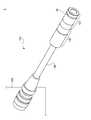
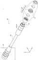
以下、図面を参照しながら、本発明の実施形態に係るUV照射装置1について説明する。図1はUV照射装置1の外観図であり、図2はその分解図である。なお、以下の説明においては、後述するレンズユニット120の光軸方向をX軸方向、後述する平凸シリンドリカルレンズ(第1レンズ20、第2レンズ40)の焦線Fの方向をY軸方向、平凸シリンドリカルレンズの集光方向をZ軸方向と呼ぶ。なお、平凸シリンドリカルレンズは焦線Fの方向(Y軸方向)には屈折力を有さず、焦線Fと垂直な方向(Z軸方向)に屈折力を有している。 Hereinafter, the
本実施形態のUV照射装置1は、箱形の電源ユニット200と、電源ユニット200の正面から延びる細長い本体ユニット100を備えている。また、本体ユニット100は、レンズユニット120、光源ユニット140及びケーブル部160を備えている。ケーブル160は、光源ユニット140に給電するための電力線や光源ユニット140の動作を制御するための信号を送る信号線が金属可撓管によって被覆保護されたものであり、電源ユニット200と本体ユニット100とを接続する。光源ユニット140は、略円筒形状のケーシング141を有し、一端にLED素子142が配置されている。光源ユニット140のケーシング141内にはLED素子142を駆動する駆動回路(不図示)が収容されており、光源ユニット140の他端はケーブル160を介して電源ユニット200に接続されている。また、光源ユニット140の一端には、レンズユニット120が取り付けられている。 The
レンズユニット120は、光源ユニット140のケーシング141と略同一の外径を有する鏡筒121と、鏡筒121内に保持された一対の平凸シリンドリカルレンズ(第1レンズ20、第2レンズ40)を備えている。第1レンズ20と第2レンズ40は、同一の形状及び光学特性を有している。鏡筒121は、光軸方向において3つの部材(光源ユニット140側から順に、入射側鏡筒部10、中間鏡筒部30、出射側鏡筒部50)に分割されている。また、第1レンズ20は入射側鏡筒部10と中間鏡筒部30の間で挟み込まれ、第2レンズ40は中間鏡筒部30と出射側鏡筒部50の間で挟み込まれ、それぞれ鏡筒121内で保持されている。 The
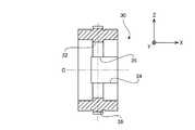
次に、中間鏡筒部30の構成について説明する。図3〜5は、順に中間鏡筒部30の正面図、側面図、及び背面図である。また、図6は、中間鏡筒部30の縦断面図である。中間鏡筒部30は略円筒形状の部材であるが、その内周面のX軸方向中央部には、内側に突出する略環状の突出部32が形成されている。図2に示すように、一対の平凸シリンドリカルレンズである第1レンズ20及び第2レンズ40は、それぞれ凸面(凸レンズ面)を中間鏡筒部30に向けて配置され、凸面側の一部が中間鏡筒部30の中空部内に収容される。図7及び図8は、第1レンズ20及び第2レンズ40の凸面側の一部が中間鏡筒部30の中空部内に挿し込まれた状態を示す図である。具体的には、図7は、第1レンズ20の焦線F20及び第2レンズ40の焦線F40をそれぞれZ軸方向に向けて各レンズを中間鏡筒部30に挿し込んだ状態を示し、図8は、焦線F20及びF40をそれぞれY軸方向に向けて各レンズを中間鏡筒部30に挿し込んだ状態を示す。図8に示す配置が、光源ユニット140の完成時の配置である。Next, the configuration of the
中間鏡筒部30の内周面には、Y軸方向両端部(図3において矢印Rwで示す箇所)に、溝34が形成されている。溝34は、中間鏡筒部30のX軸正方向側の端(図6における右端)から突出部32を越えた位置まで形成されている。その為、突出部32のY軸方向両端部には切欠部35(図5)が設けられている。
図3及び図8に示すように、突出部32における中間鏡筒部30の内径Rn(例えばφ7.5mm)は、第1レンズ20及び第2レンズ40の外径(例えばφ8.2mm)よりも狭く成形されている。また、突出部32が形成されていない箇所における中間鏡筒部30の内径Rw(例えばφ8.2[プラス公差]mm)は、第1レンズ20及び第2レンズ40の外径よりもわずかに広く成形されている。従って、第1レンズ20及び第2レンズ40を中間鏡筒部30の中空部に挿し込んでも、第1レンズ20及び第2レンズ40の凸面の少なくとも一部が突出部32に当接して、それ以上に奥には入らない状態となる。 As shown in FIGS. 3 and 8, the inner diameter Rn (for example, φ7.5 mm) of the
図7に示すように、第1レンズ20及び第2レンズ40を、各焦線F20及びF40を突出部32の溝34が形成されていない方向(例えばZ軸方向)に向けて、中間鏡筒部30の中空部に挿し込むと、第1レンズ20及び第2レンズ40の凸面の頂点Vが突出部32に当接する。この状態で、第1レンズ20及び第2レンズ40を突出部32に押し当てながら、中間鏡筒部30の中心軸Cの周りに回転させて、各焦線F20及びF40の方向を溝34が形成されたY軸方向に合わせると、図8に示すように、突出部32が形成されていない切欠部35に第1レンズ20及び第2レンズ40の凸面の先端部(頂点V及びその近傍の部分)が嵌り込み、これにより第1レンズ20及び第2レンズ40が正しい位置に位置決めされる。すなわち、第1レンズ20と第2レンズ40の光軸C及び焦線F20、F40の方向が略完全に一致する。また、各レンズ20、40の凸面の先端部が切欠部35に嵌り込むことにより、各レンズを中間鏡筒部30に押し込んだ状態では、各レンズは中心軸Cの周りに回転し難くなる。そのため、第1レンズ20及び第2レンズ40の焦線F20及びF40の方向は、それぞれ中間鏡筒部30に対して正しい方向に保たれる。また、溝34のZ軸方向の寸法により、第1レンズ20と第2レンズ40との間隔も正確に設定することができる。As shown in FIG. 7, the
また、中間鏡筒部30の側面におけるZ軸方向両端には、光軸方向に延びるマーカー溝36が高い位置精度で形成されている。ユーザは、本体ユニット100を設置する際に、マーカー溝36の向きによって、本体ユニット100から照射される照射光の長径方向を正確に認識することができるため、UV照射装置1を作動させることなく、本体ユニット100の位置決めを正確かつ容易に行うことができる。 Further,
上記に説明した本実施形態の本体ユニット100をY軸方向に所定間隔で複数並べることにより、長いライン状の照射領域を形成することができる。図9は、複数の本体ユニット100(100A〜D)を備えた照射モジュール1000の外観図である。照射モジュール1000は、Y軸方向に並べられた4個の本体ユニット100A〜Dと、これらを連結する連結ブロック300を備える。連結ブロック300には、X軸方向に貫通する4つの貫通穴310がY軸方向に等間隔で形成されている。各貫通穴310はレンズユニット120の外径よりも僅かに大きな内径を有しており、各貫通穴310には、それぞれ本体ユニット100A〜Dのレンズユニット120が挿し込まれている。また、連結ブロック300には、各貫通穴310の中心軸を通るZ軸上にタップ穴320が貫通している。本体ユニット100A〜Dは、タップ穴320に捩じ込まれた止めねじ(不図示)によって、連結ブロック300に固定されている。また、連結ブロック300の出射側(X軸正方向側)の面には、各貫通穴310の上端からZ軸方向に延びるマーカー溝330が形成されている。 A long line-shaped irradiation region can be formed by arranging a plurality of the
照射モジュール1000は、次のようにして組み立てられる。先ず、連結ブロック300の各貫通穴310に本体ユニット100Aのレンズユニット120を出射側鏡筒部50から入射側鏡筒部10まで(中間鏡筒部30が貫通穴310を通り抜けるまで)挿し込む。このとき、各レンズユニット120からの照射光の照射領域における強度が均一になるように、連結ブロック300の出射側の端面から各レンズユニット120の先端がX軸方向に突出する長さを正確に一致させる。次に、本体ユニット100Aを回転させて、中間鏡筒部30の側面に設けられたマーカー溝36を連結ブロック300の出射側面に形成されたマーカー溝330の位置に合わせ、その状態で止めねじにより本体ユニット100Aを連結ブロック300に固定する。この手順を本体ユニット100B〜Dについても行うことにより、照射モジュール1000が完成する。 The
上述のように、マーカー溝36は、レンズユニット120の光軸(X軸)を通り、焦線方向(Y軸方向)と直交する平面(ZX平面)上に形成されている。また、マーカー溝330は、貫通穴310の中心軸を通り、貫通穴310の配列方向と直交する平面上に形成されている。レンズユニット120は貫通穴310内に略隙間無く収容されるため、レンズユニット120の光軸(X軸)は貫通穴310の中心軸上に配置される。また、本体ユニット100A〜Dを回転させてマーカー溝36をマーカー溝330の位置に合わせることにより、レンズユニット120の焦線方向(Y軸方向)が貫通穴310の配列方向と一致する。従って、4つの本体ユニット100A〜Dから出射するライン状の照明光は、隣接する照明光と裾の部分が重なり合って、Y軸方向に延びる一本のライン状の照明光を形成する。 As described above, the
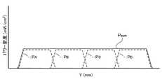
図10は、照射モジュール1000から出射する照明光のY軸方向におけるビームプロファイルを説明するグラフである。図10のグラフの横軸はY軸方向の位置を示し、縦軸は各位置における照射モジュール1000の照射光の強度(照度)を示す。なお、照射光の強度分布(照度分布)は、照射モジュール1000からの距離によって変化する。図10のグラフは、照射モジュール1000の先端から所定の設計距離(例えば28mm)離れた位置における強度を示す。 FIG. 10 is a graph for explaining a beam profile in the Y-axis direction of illumination light emitted from the
図10における実線PSUMは、照射モジュール1000全体のビームプロファイルであり、破線PA〜PDは、それぞれ本体ユニット100A〜Dの単体が照射する光束のビームプロファイルである。本実施形態においては、各本体ユニット100のビームプロファイルのY軸方向における半値全幅に等しい間隔で本体ユニット100A〜DがY軸方向に配列されている。そのため、隣接する各本体ユニット100の照射光の裾の部分が重なり合い、各本体ユニット100の照射光の境界部分においても略平坦なビームプロファイルが得られている。液晶パネルの張り合わせ工程のような広い面積の接着を行う際には、このように、一方向に長く平坦なビームプロファイルを有する紫外線照射光を使用することにより、均質な接着を効率的に行うことが可能になる。The solid lineP SUM in Fig. 10 is a beam profile of the
以上が、本発明の実施形態の一例の説明であるが、本発明は、上記の実施形態の構成に限定されるものではなく、特許請求の範囲の記載によって表現された技術的思想の範囲内において様々な変形が可能である。 The above is the description of an example of the embodiment of the present invention. However, the present invention is not limited to the configuration of the above embodiment, and is within the scope of the technical idea expressed by the description of the scope of claims. Various modifications are possible.
上記の実施形態では、レンズユニット120に凸レンズ面同士を向かい合わせて配置した一対の平凸シリンドリカルレンズが使用されているが、外側のレンズ面の形状は平面に限定されず、例えば外側のレンズ面も凸面にした両凸レンズ(図11(A)を参照)や、外側のレンズ面を凹面にした正の屈折力を有する凹凸レンズを使用した構成(図11(B)を参照)としてもよい。さらに、上記の実施形態では、凸レンズ面同士を向かい合わせて配置したそれぞれのレンズが同一の形状を呈しているが、必ずしも同一形状に限定されず、異形のものを組合せて採用すること(図11(C)を参照)が可能である。 In the above embodiment, a pair of plano-convex cylindrical lenses are used in which the convex lens surfaces are arranged facing each other on the
また、上記の実施形態は光源としてLEDを使用したものであるが、別の種類の光源(例えば、水銀ランプやメタルハライドランプ等の放電ランプや半導体レーザ)を使用することもできる。また、上記の実施形態は、光源ユニットにレンズユニットが直接接続された構成のものであるが、バンドルファイバ等のライトガイドを介して光源ユニットにレンズユニットが接続された構成とすることもできる。 Moreover, although said embodiment uses LED as a light source, another kind of light source (For example, discharge lamps, such as a mercury lamp and a metal halide lamp, and a semiconductor laser) can also be used. In the above-described embodiment, the lens unit is directly connected to the light source unit. However, the lens unit may be connected to the light source unit via a light guide such as a bundle fiber.
また、上記の実施形態は、マーカー溝36が中間鏡筒部30の側面におけるZ軸方向(照射光の長径方向)の両端に形成された構成であるが、片端のみにマーカー溝を形成した構成としてもよい。また、マーカー溝36を中間鏡筒部30の側面におけるY軸方向(照射光の短径方向)の少なくとも一端に形成する構成としてもよい。 In the above-described embodiment, the
1 UV照射装置
10 入射側鏡筒部
20 第1レンズ
30 中間鏡筒部
32 突出部
34 溝
36 マーカー溝
40 第2レンズ
50 出射側鏡筒部
100 本体ユニット
120 レンズユニット
121 鏡筒
140 光源ユニット
141 ケーシング
142 LED素子
160 ケーブル
200 電源ユニット
300 連結ブロック
310 貫通穴
330 マーカー溝
1000 照射モジュール
F20、F40 焦線
Rn 内径(突出部)
Rw 内径(切欠部)DESCRIPTION OF
Rw Inner diameter (notch)
Claims (10)
Translated fromJapaneseそれぞれ第1面に凸レンズ面が形成されたシリンドリカルレンズである第1及び第2のレンズと、
前記第1及び前記第2のレンズを、前記凸レンズ面同士が所定の距離を置いて対向し、且つ各光軸が一致するように保持する鏡筒と、
を備え、
前記鏡筒は、前記第1及び前記第2のレンズの焦線が前記光軸に垂直な第1の方向に向くように各レンズの前記凸レンズ面の先端部と嵌合し、各レンズの回転を規制すると共に各レンズを位置決めする中間鏡筒部を備え、
前記中間鏡筒部の外周面には、前記光軸を通り、前記第1の方向又は前記光軸及び前記第1の方向に垂直な第2の方向に延びる直線上の少なくとも一箇所にマーカーが形成されていることを特徴とするレンズユニット。A lens unit that collects incident light flux and emits illumination light having a linear illumination distribution,
First and second lenses, which are cylindrical lenses each having a convex lens surface formed on the first surface;
A lens barrel that holds the first and second lenses so that the convex lens surfaces face each other at a predetermined distance and the respective optical axes coincide;
With
The lens barrelisfitted to the tip of the convex lens surface of each lens so that the focal lines of the first and second lenses are directed in a first direction perpendicular to the optical axis, and the rotation of each lens And includesan intermediate lens barrelthat positions each lens .
On the outer peripheral surface of the intermediate barrel portion, there is a marker in at least one place on a straight line that passes throughtheoptical axis andextends in the firstdirection ora second directionperpendicular to theoptical axis and the first direction. A lens unit that is formed.
前記突出部には、前記光軸を通り前記第1の方向に延びる直線上に、前記光軸を挟んで一対の切欠部が設けられており、
前記第1及び前記第2のレンズの前記凸レンズ面の先端部がそれぞれ前記一対の切欠部に嵌り込むことを特徴とする請求項1に記載のレンズユニット。The intermediate lens barrel portion has a protrusion protruding from the inner peripheral surface of the intermediate lens barrel portion toward the central axis;
The projecting portion is provided with a pair of notches on the straight line passing through the optical axis and extending in thefirst direction with the optical axis interposed therebetween,
2. The lens unit according to claim 1, wherein tip portions of the convex lens surfaces of the first and second lenses are fitted into the pair of cutout portions, respectively.
前記中間鏡筒部が、前記第1及び前記第2のレンズの外径よりもわずかに内径が広い内周面を有する略円筒状であり、前記第1及び前記第2のレンズの前記凸レンズ面側の少なくとも一部をそれぞれ該中間鏡筒部の中空部内に収容し、
前記突出部が、前記第1及び前記第2のレンズの外径よりも狭い内径を有する略円環状に形成されていることを特徴とする請求項2に記載のレンズユニット。The first and second lenses each have a cylindrical side surface;
The intermediate lens barrel has a substantially cylindrical shape having an inner peripheral surface slightly wider in outer diameter than the outer diameters of the first and second lenses, and the convex lens surfaces of the first and second lenses. Accommodate at least a part of each side in the hollow part of the intermediate lens barrel part,
3. The lens unit according to claim 2, wherein the projecting portion is formed in a substantially annular shape having an inner diameter narrower than outer diameters of the first and second lenses.
前記光源ユニットが出射した光束を前記第2の方向に集光する、請求項1から請求項6のいずれか一項に記載のレンズユニットと、
を備え、前記第1の方向に長いライン状の照射領域を有する照射光を生成する光照射ユニット。A light source unit;
The lens unit according to any one of claims 1 to 6, wherein the light beam emitted from the light source unit is collected in thesecond direction.
A light irradiation unit that generates irradiation light having a linear irradiation region that is long in thefirst direction.
前記複数の光照射ユニットは、前記光軸を互いに平行にして前記第1の方向に所定間隔で並べられており、
前記所定間隔は、前記光照射ユニットの照射光の照射領域における前記第1の方向の半値全幅と同じ長さであることを特徴とする光照射装置。A plurality of light irradiation units according to any one of claims 7 to 9,
The plurality of light irradiation units are arranged at predetermined intervals in thefirst direction with the optical axes parallel to each other.
The said predetermined space | interval is the same length as the full width at half maximum of the said1st direction in the irradiation area | region of the irradiation light of the said light irradiation unit, The light irradiation apparatus characterized by the above-mentioned.
Priority Applications (4)
| Application Number | Priority Date | Filing Date | Title |
|---|---|---|---|
| JP2012078936AJP5538467B2 (en) | 2012-03-30 | 2012-03-30 | Lens unit, light irradiation unit and light irradiation device |
| TW102107631ATWI539196B (en) | 2012-03-30 | 2013-03-05 | A lens unit, a light irradiation unit, and a light irradiation device |
| KR1020130029687AKR101599936B1 (en) | 2012-03-30 | 2013-03-20 | Lens unit, the light irradiation unit, the light irradiation apparatus |
| CN201310109426.6ACN103363442B (en) | 2012-03-30 | 2013-03-29 | Lens unit, light irradiation unit and light irradiation device |
Applications Claiming Priority (1)
| Application Number | Priority Date | Filing Date | Title |
|---|---|---|---|
| JP2012078936AJP5538467B2 (en) | 2012-03-30 | 2012-03-30 | Lens unit, light irradiation unit and light irradiation device |
Publications (2)
| Publication Number | Publication Date |
|---|---|
| JP2013210422A JP2013210422A (en) | 2013-10-10 |
| JP5538467B2true JP5538467B2 (en) | 2014-07-02 |
Family
ID=49365389
Family Applications (1)
| Application Number | Title | Priority Date | Filing Date |
|---|---|---|---|
| JP2012078936AActiveJP5538467B2 (en) | 2012-03-30 | 2012-03-30 | Lens unit, light irradiation unit and light irradiation device |
Country Status (4)
| Country | Link |
|---|---|
| JP (1) | JP5538467B2 (en) |
| KR (1) | KR101599936B1 (en) |
| CN (1) | CN103363442B (en) |
| TW (1) | TWI539196B (en) |
Cited By (1)
| Publication number | Priority date | Publication date | Assignee | Title |
|---|---|---|---|---|
| CN104483816A (en)* | 2014-12-19 | 2015-04-01 | 中国科学院长春光学精密机械与物理研究所 | Type critical illumination system for extreme ultra-violet lithography |
Families Citing this family (3)
| Publication number | Priority date | Publication date | Assignee | Title |
|---|---|---|---|---|
| JP6139450B2 (en)* | 2014-03-27 | 2017-05-31 | Hoya Candeo Optronics株式会社 | Light irradiation unit and light irradiation device |
| JP6125456B2 (en)* | 2014-03-31 | 2017-05-10 | Hoya Candeo Optronics株式会社 | Light irradiation unit |
| KR200490462Y1 (en)* | 2017-09-15 | 2019-11-14 | 이태호 | Projection-typed Luminescent Display Apparatus adaptable for billiard table |
Family Cites Families (11)
| Publication number | Priority date | Publication date | Assignee | Title |
|---|---|---|---|---|
| CN2044353U (en)* | 1988-12-30 | 1989-09-13 | 大连医学院 | Multi-purpose jionter for endoscope camera |
| JP2006139874A (en)* | 2004-11-12 | 2006-06-01 | Konica Minolta Opto Inc | Lens unit and optical pickup device |
| JP2007027295A (en) | 2005-07-14 | 2007-02-01 | Ushio Inc | UV irradiation equipment |
| US7518745B2 (en) | 2005-09-28 | 2009-04-14 | Xerox Corporation | Imaging system with haptic interface |
| JP2008090260A (en)* | 2006-09-07 | 2008-04-17 | Seiko Epson Corp | Ultraviolet irradiation device and optical device manufacturing apparatus |
| JP5121771B2 (en) | 2008-09-19 | 2013-01-16 | 三菱電機株式会社 | Light source unit and image display device |
| JP2010097178A (en)* | 2008-09-22 | 2010-04-30 | Mitsubishi Electric Corp | Light source unit and image display apparatus |
| JP4741017B2 (en)* | 2008-09-22 | 2011-08-03 | 三菱電機株式会社 | Light source unit and image display device |
| JP3151132U (en)* | 2009-03-30 | 2009-06-11 | 扶桑電機工業株式会社 | Line irradiation type ultraviolet irradiation device |
| JP2011175058A (en)* | 2010-02-24 | 2011-09-08 | Kyocera Mita Corp | Optical scanner and image forming apparatus |
| CN102388336A (en)* | 2010-07-20 | 2012-03-21 | 株式会社爱发科 | Light irradiation device |
- 2012
- 2012-03-30JPJP2012078936Apatent/JP5538467B2/enactiveActive
- 2013
- 2013-03-05TWTW102107631Apatent/TWI539196B/enactive
- 2013-03-20KRKR1020130029687Apatent/KR101599936B1/ennot_activeExpired - Fee Related
- 2013-03-29CNCN201310109426.6Apatent/CN103363442B/enactiveActive
Cited By (2)
| Publication number | Priority date | Publication date | Assignee | Title |
|---|---|---|---|---|
| CN104483816A (en)* | 2014-12-19 | 2015-04-01 | 中国科学院长春光学精密机械与物理研究所 | Type critical illumination system for extreme ultra-violet lithography |
| CN104483816B (en)* | 2014-12-19 | 2016-10-26 | 中国科学院长春光学精密机械与物理研究所 | A kind of class critical illumination system for extreme ultraviolet photolithographic |
Also Published As
| Publication number | Publication date |
|---|---|
| TWI539196B (en) | 2016-06-21 |
| KR101599936B1 (en) | 2016-03-04 |
| JP2013210422A (en) | 2013-10-10 |
| KR20130111321A (en) | 2013-10-10 |
| TW201350907A (en) | 2013-12-16 |
| CN103363442B (en) | 2017-07-11 |
| CN103363442A (en) | 2013-10-23 |
Similar Documents
| Publication | Publication Date | Title |
|---|---|---|
| TWI613093B (en) | Light irradiation device | |
| JP5473534B2 (en) | Light source device | |
| JP7438209B2 (en) | Optical units and vehicle lights | |
| CN109690887B (en) | Light output module and LIDAR | |
| WO2014171317A1 (en) | Photoirradiation device | |
| US9857672B2 (en) | Light source unit, lighting apparatus and image projection apparatus | |
| KR20110118815A (en) | LED lighting device | |
| JP5538467B2 (en) | Lens unit, light irradiation unit and light irradiation device | |
| US20080084612A1 (en) | Apparatus for generating a homogeneous angular distribution of laser irradiation | |
| US20150146424A1 (en) | Led lighting device | |
| JP2011060798A (en) | Ultraviolet irradiation device | |
| KR101401238B1 (en) | LED light source apparatus for exposure resist | |
| JP2017122906A (en) | Light irradiating device | |
| CN104104013A (en) | Split type semiconductor laser diode energy beam combination device | |
| KR101831374B1 (en) | Light illuminating apparatus | |
| KR102085955B1 (en) | A lighting device using a led | |
| JP5876740B2 (en) | Lighting device | |
| KR101427109B1 (en) | Optical structure of pattern image projector | |
| KR101987146B1 (en) | Focusing module, LED Light Source Device having Focusing module, and vision inspection apparatus | |
| JP3145280U (en) | Light irradiation device | |
| JP2007042517A (en) | Light irradiation apparatus | |
| JP2006318813A (en) | Light irradiation apparatus having optical component and method of mounting optical component | |
| KR20140119533A (en) | Light source unit and method of manufacturing the same |
Legal Events
| Date | Code | Title | Description |
|---|---|---|---|
| A977 | Report on retrieval | Free format text:JAPANESE INTERMEDIATE CODE: A971007 Effective date:20140115 | |
| A131 | Notification of reasons for refusal | Free format text:JAPANESE INTERMEDIATE CODE: A131 Effective date:20140127 | |
| A977 | Report on retrieval | Free format text:JAPANESE INTERMEDIATE CODE: A971007 Effective date:20140220 | |
| A521 | Request for written amendment filed | Free format text:JAPANESE INTERMEDIATE CODE: A523 Effective date:20140325 | |
| TRDD | Decision of grant or rejection written | ||
| A01 | Written decision to grant a patent or to grant a registration (utility model) | Free format text:JAPANESE INTERMEDIATE CODE: A01 Effective date:20140421 | |
| R150 | Certificate of patent or registration of utility model | Ref document number:5538467 Country of ref document:JP Free format text:JAPANESE INTERMEDIATE CODE: R150 | |
| A61 | First payment of annual fees (during grant procedure) | Free format text:JAPANESE INTERMEDIATE CODE: A61 Effective date:20140428 | |
| R250 | Receipt of annual fees | Free format text:JAPANESE INTERMEDIATE CODE: R250 | |
| R250 | Receipt of annual fees | Free format text:JAPANESE INTERMEDIATE CODE: R250 | |
| R250 | Receipt of annual fees | Free format text:JAPANESE INTERMEDIATE CODE: R250 | |
| S111 | Request for change of ownership or part of ownership | Free format text:JAPANESE INTERMEDIATE CODE: R313111 | |
| R350 | Written notification of registration of transfer | Free format text:JAPANESE INTERMEDIATE CODE: R350 | |
| R250 | Receipt of annual fees | Free format text:JAPANESE INTERMEDIATE CODE: R250 | |
| R250 | Receipt of annual fees | Free format text:JAPANESE INTERMEDIATE CODE: R250 | |
| R250 | Receipt of annual fees | Free format text:JAPANESE INTERMEDIATE CODE: R250 | |
| R250 | Receipt of annual fees | Free format text:JAPANESE INTERMEDIATE CODE: R250 | |
| R250 | Receipt of annual fees | Free format text:JAPANESE INTERMEDIATE CODE: R250 | |
| R250 | Receipt of annual fees | Free format text:JAPANESE INTERMEDIATE CODE: R250 |