JP5536160B2 - Intake control device for internal combustion engine - Google Patents
Intake control device for internal combustion engineDownload PDFInfo
- Publication number
- JP5536160B2 JP5536160B2JP2012192281AJP2012192281AJP5536160B2JP 5536160 B2JP5536160 B2JP 5536160B2JP 2012192281 AJP2012192281 AJP 2012192281AJP 2012192281 AJP2012192281 AJP 2012192281AJP 5536160 B2JP5536160 B2JP 5536160B2
- Authority
- JP
- Japan
- Prior art keywords
- intake air
- air amount
- target
- temporary
- torque
- Prior art date
- Legal status (The legal status is an assumption and is not a legal conclusion. Google has not performed a legal analysis and makes no representation as to the accuracy of the status listed.)
- Expired - Fee Related
Links
Images


Classifications
- F—MECHANICAL ENGINEERING; LIGHTING; HEATING; WEAPONS; BLASTING
- F02—COMBUSTION ENGINES; HOT-GAS OR COMBUSTION-PRODUCT ENGINE PLANTS
- F02D—CONTROLLING COMBUSTION ENGINES
- F02D41/00—Electrical control of supply of combustible mixture or its constituents
- F02D41/0002—Controlling intake air
- F—MECHANICAL ENGINEERING; LIGHTING; HEATING; WEAPONS; BLASTING
- F02—COMBUSTION ENGINES; HOT-GAS OR COMBUSTION-PRODUCT ENGINE PLANTS
- F02D—CONTROLLING COMBUSTION ENGINES
- F02D11/00—Arrangements for, or adaptations to, non-automatic engine control initiation means, e.g. operator initiated
- F02D11/06—Arrangements for, or adaptations to, non-automatic engine control initiation means, e.g. operator initiated characterised by non-mechanical control linkages, e.g. fluid control linkages or by control linkages with power drive or assistance
- F02D11/10—Arrangements for, or adaptations to, non-automatic engine control initiation means, e.g. operator initiated characterised by non-mechanical control linkages, e.g. fluid control linkages or by control linkages with power drive or assistance of the electric type
- F02D11/105—Arrangements for, or adaptations to, non-automatic engine control initiation means, e.g. operator initiated characterised by non-mechanical control linkages, e.g. fluid control linkages or by control linkages with power drive or assistance of the electric type characterised by the function converting demand to actuation, e.g. a map indicating relations between an accelerator pedal position and throttle valve opening or target engine torque
- F—MECHANICAL ENGINEERING; LIGHTING; HEATING; WEAPONS; BLASTING
- F02—COMBUSTION ENGINES; HOT-GAS OR COMBUSTION-PRODUCT ENGINE PLANTS
- F02D—CONTROLLING COMBUSTION ENGINES
- F02D37/00—Non-electrical conjoint control of two or more functions of engines, not otherwise provided for
- F02D37/02—Non-electrical conjoint control of two or more functions of engines, not otherwise provided for one of the functions being ignition
- F—MECHANICAL ENGINEERING; LIGHTING; HEATING; WEAPONS; BLASTING
- F02—COMBUSTION ENGINES; HOT-GAS OR COMBUSTION-PRODUCT ENGINE PLANTS
- F02D—CONTROLLING COMBUSTION ENGINES
- F02D41/00—Electrical control of supply of combustible mixture or its constituents
- F02D41/02—Circuit arrangements for generating control signals
- F02D41/14—Introducing closed-loop corrections
- F02D41/1401—Introducing closed-loop corrections characterised by the control or regulation method
- F02D41/1406—Introducing closed-loop corrections characterised by the control or regulation method with use of a optimisation method, e.g. iteration
- F—MECHANICAL ENGINEERING; LIGHTING; HEATING; WEAPONS; BLASTING
- F02—COMBUSTION ENGINES; HOT-GAS OR COMBUSTION-PRODUCT ENGINE PLANTS
- F02P—IGNITION, OTHER THAN COMPRESSION IGNITION, FOR INTERNAL-COMBUSTION ENGINES; TESTING OF IGNITION TIMING IN COMPRESSION-IGNITION ENGINES
- F02P5/00—Advancing or retarding ignition; Control therefor
- F02P5/04—Advancing or retarding ignition; Control therefor automatically, as a function of the working conditions of the engine or vehicle or of the atmospheric conditions
- F02P5/145—Advancing or retarding ignition; Control therefor automatically, as a function of the working conditions of the engine or vehicle or of the atmospheric conditions using electrical means
- F02P5/15—Digital data processing
- F02P5/152—Digital data processing dependent on pinking
- F—MECHANICAL ENGINEERING; LIGHTING; HEATING; WEAPONS; BLASTING
- F02—COMBUSTION ENGINES; HOT-GAS OR COMBUSTION-PRODUCT ENGINE PLANTS
- F02D—CONTROLLING COMBUSTION ENGINES
- F02D41/00—Electrical control of supply of combustible mixture or its constituents
- F02D41/0002—Controlling intake air
- F02D2041/001—Controlling intake air for engines with variable valve actuation
- F—MECHANICAL ENGINEERING; LIGHTING; HEATING; WEAPONS; BLASTING
- F02—COMBUSTION ENGINES; HOT-GAS OR COMBUSTION-PRODUCT ENGINE PLANTS
- F02D—CONTROLLING COMBUSTION ENGINES
- F02D41/00—Electrical control of supply of combustible mixture or its constituents
- F02D41/0002—Controlling intake air
- F02D2041/0017—Controlling intake air by simultaneous control of throttle and exhaust gas recirculation
- F—MECHANICAL ENGINEERING; LIGHTING; HEATING; WEAPONS; BLASTING
- F02—COMBUSTION ENGINES; HOT-GAS OR COMBUSTION-PRODUCT ENGINE PLANTS
- F02D—CONTROLLING COMBUSTION ENGINES
- F02D2200/00—Input parameters for engine control
- F02D2200/02—Input parameters for engine control the parameters being related to the engine
- F02D2200/10—Parameters related to the engine output, e.g. engine torque or engine speed
- F02D2200/1002—Output torque
- F—MECHANICAL ENGINEERING; LIGHTING; HEATING; WEAPONS; BLASTING
- F02—COMBUSTION ENGINES; HOT-GAS OR COMBUSTION-PRODUCT ENGINE PLANTS
- F02D—CONTROLLING COMBUSTION ENGINES
- F02D41/00—Electrical control of supply of combustible mixture or its constituents
- F02D41/0025—Controlling engines characterised by use of non-liquid fuels, pluralities of fuels, or non-fuel substances added to the combustible mixtures
- F02D41/0047—Controlling exhaust gas recirculation [EGR]
- F02D41/005—Controlling exhaust gas recirculation [EGR] according to engine operating conditions
- F—MECHANICAL ENGINEERING; LIGHTING; HEATING; WEAPONS; BLASTING
- F02—COMBUSTION ENGINES; HOT-GAS OR COMBUSTION-PRODUCT ENGINE PLANTS
- F02D—CONTROLLING COMBUSTION ENGINES
- F02D41/00—Electrical control of supply of combustible mixture or its constituents
- F02D41/02—Circuit arrangements for generating control signals
- F02D41/14—Introducing closed-loop corrections
- Y—GENERAL TAGGING OF NEW TECHNOLOGICAL DEVELOPMENTS; GENERAL TAGGING OF CROSS-SECTIONAL TECHNOLOGIES SPANNING OVER SEVERAL SECTIONS OF THE IPC; TECHNICAL SUBJECTS COVERED BY FORMER USPC CROSS-REFERENCE ART COLLECTIONS [XRACs] AND DIGESTS
- Y02—TECHNOLOGIES OR APPLICATIONS FOR MITIGATION OR ADAPTATION AGAINST CLIMATE CHANGE
- Y02T—CLIMATE CHANGE MITIGATION TECHNOLOGIES RELATED TO TRANSPORTATION
- Y02T10/00—Road transport of goods or passengers
- Y02T10/10—Internal combustion engine [ICE] based vehicles
- Y02T10/40—Engine management systems
Landscapes
- Engineering & Computer Science (AREA)
- Chemical & Material Sciences (AREA)
- Combustion & Propulsion (AREA)
- Mechanical Engineering (AREA)
- General Engineering & Computer Science (AREA)
- Signal Processing (AREA)
- Combined Controls Of Internal Combustion Engines (AREA)
- Electrical Control Of Air Or Fuel Supplied To Internal-Combustion Engine (AREA)
Description
Translated fromJapanese本発明は、目標トルクに応じて目標吸気量を設定し、吸気量を制御する内燃機関の吸気制御装置に関する。 The present invention relates to an intake control device for an internal combustion engine that sets a target intake air amount according to a target torque and controls the intake air amount.
従来の内燃機関の吸気制御装置として、例えば特許文献1に記載されたものが知られている。この吸気制御装置では、内燃機関の目標トルクに応じて、目標吸気量が次のように設定される。まず、目標吸気量の暫定値である仮目標吸気量を初期値に設定する。次に、そのときの内燃機関の運転状態に応じ、この仮目標吸気量の吸気を内燃機関に供給したと仮定したときに設定されると推定される点火時期の推定リタード量を算出する。次に、これらの仮目標吸気量及び推定リタード量の条件の下で、内燃機関から出力されると推定されるトルクを、推定トルクとして算出する。 As a conventional intake control device for an internal combustion engine, for example, one described in
算出された推定トルクと目標トルクとの差が大きい場合には、推定トルクが目標トルクに近づくように、仮目標吸気量を修正する。具体的には、推定トルクが目標トルクよりも大きい場合には、仮目標吸気量を減少させ、逆の場合には、仮目標吸気量を増加させる。修正した仮目標吸気量に基づき、推定リタード量及び推定トルクを再度、算出する。そして、そのような処理を、推定トルクが目標トルクに収束するまで繰り返し行い、収束した時点における仮目標吸気量が、目標トルクを達成する目標吸気量として設定される。また、上記の処理を所定回数、実行しても、推定トルクが目標トルクに収束しない場合には、その時点での仮目標吸気量が目標吸気量として設定される。 When the difference between the calculated estimated torque and the target torque is large, the temporary target intake air amount is corrected so that the estimated torque approaches the target torque. Specifically, when the estimated torque is larger than the target torque, the temporary target intake air amount is decreased, and in the opposite case, the temporary target intake air amount is increased. Based on the corrected temporary target intake air amount, the estimated retard amount and the estimated torque are calculated again. Such processing is repeated until the estimated torque converges to the target torque, and the temporary target intake air amount at the time of convergence is set as the target intake air amount that achieves the target torque. Further, if the estimated torque does not converge to the target torque even after the above process is performed a predetermined number of times, the temporary target intake air amount at that time is set as the target intake air amount.
内燃機関で燃焼する混合気の空燃比が一定値、例えば理論空燃比に制御される場合、通常、内燃機関のトルクは、吸気量が増加するにつれて、増加するという特性を有する。上述した従来の吸気制御装置は、そのようなトルクの出力特性を前提にしている。しかし、例えば、内燃機関が、高圧縮比エンジンで、特に高水温時や高吸気温時など、ノッキングを抑制するための点火時期のリタード量が比較的大きく設定されるような場合には、点火時期のリタードによる燃焼効率の低下により、吸気量が増加しても、内燃機関のトルクが増加しないか又は減少するという事象が生じる。その場合には、1つの目標トルクに対して、それを達成する複数の吸気量の解が存在することになる。 When the air-fuel ratio of the air-fuel mixture combusted in the internal combustion engine is controlled to a constant value, for example, the stoichiometric air-fuel ratio, the torque of the internal combustion engine usually has a characteristic of increasing as the intake air amount increases. The conventional intake control apparatus described above is based on such torque output characteristics. However, for example, when the internal combustion engine is a high compression ratio engine and the retard amount of the ignition timing for suppressing knocking is set to be relatively large, particularly at high water temperature or high intake air temperature, Due to the decrease in combustion efficiency due to the retard of the timing, an event occurs in which the torque of the internal combustion engine does not increase or decreases even when the intake air amount increases. In that case, for one target torque, there are a plurality of intake air amount solutions for achieving the target torque.
これに対し、従来の吸気制御装置では、仮目標吸気量の初期値から出発し、仮目標吸気量の修正と、修正された仮目標吸気量に基づいて推定された推定トルクの目標トルクへの収束状態の確認とを繰り返しながら、目標トルクを達成する吸気量を見出すという手法が採用されている。このため、仮目標吸気量の初期値の設定の仕方などによっては、上記の複数の吸気量の解のうち、より大きな吸気量の解を選択する可能性がある。その場合には、選択されたより大きな吸気量に応じて、トルクの増加に寄与しない余分な燃料が消費されるため、燃費が悪化する。また、例えば、仮目標吸気量がより大きな側の吸気量の解よりも大きな値に設定された場合には、仮目標吸気量がさらに増加側に誤って修正されるなど、仮目標吸気量の修正のハンチングが生じ、推定トルクが目標トルクに良好に収束せず、やはり目標吸気量を適切に設定できないおそれがある。 On the other hand, in the conventional intake control device, starting from the initial value of the temporary target intake air amount, the correction of the temporary target intake air amount and the estimated torque estimated based on the corrected temporary target intake air amount to the target torque are performed. A method of finding the intake air amount that achieves the target torque while repeating the confirmation of the convergence state is adopted. For this reason, depending on how the initial value of the temporary target intake air amount is set, there is a possibility of selecting a larger intake air amount solution from among the plurality of intake air amount solutions. In that case, since the excess fuel which does not contribute to the increase in torque is consumed according to the selected larger intake air amount, the fuel consumption deteriorates. In addition, for example, when the temporary target intake air amount is set to a value larger than the solution of the larger intake air amount, the temporary target intake air amount is further corrected to the increase side and the temporary target intake air amount Correction hunting occurs, the estimated torque does not converge well to the target torque, and the target intake air amount may not be set appropriately.
本発明は、このような課題を解決するためになされたものであり、1つの目標トルクを達成する複数の吸気量が存在する場合においても、そのうちの最小の吸気量を、ハンチングを生じることなく確実に選択し、目標吸気量として設定でき、それにより、燃費を向上させることができる内燃機関の吸気制御装置を提供することを目的とする。 The present invention has been made to solve such a problem, and even when there are a plurality of intake air amounts that achieve one target torque, the minimum intake air amount is not caused to cause hunting. An object of the present invention is to provide an intake control device for an internal combustion engine that can be reliably selected and set as a target intake air amount, thereby improving fuel efficiency.
この目的を達成するために、請求項1に係る発明は、内燃機関3の目標トルクTRQCMDに応じて目標吸気量GAIRCMDを設定し、設定された目標吸気量GAIRCMDに基づいて吸気量GAIRを制御する内燃機関の吸気制御装置であって、内燃機関3の運転状態(実施形態における(以下、本項において同じ)目標吸気カム位相CAINCMD、エンジン回転数NE)に基づいて、燃焼室3dに吸入可能な最大の吸気量を、最大吸気量GAIRMAXとして算出する最大吸気量算出手段(ECU2、図4のステップ3)と、値0から算出された最大吸気量GAIRMAXまでの吸気量の範囲内で、互いに異なる複数の仮吸気量GAIRPRViを設定する仮吸気量設定手段(ECU2、図4のステップ4)と、内燃機関3の運転状態(エンジン回転数NE、エンジン水温TW、吸気温TA、ノッキングの発生状態)に基づいて、設定された複数の仮吸気量GAIRPRViの吸気がそれぞれ燃焼室3dに吸入されたと仮定したときに前記内燃機関から出力されると推定されるトルクを、複数の推定トルクトルクTRQESTiとして算出する推定トルク算出手段(ECU2、図3のステップ6、図4)と、複数の仮吸気量GAIRPRViと算出された複数の推定トルクTRQESTiとの関係である仮吸気量−推定トルク関係を設定する仮吸気量−推定トルク関係設定手段(ECU2、図4、図8〜図11)と、設定された仮吸気量−推定トルク関係から、推定トルクTRQESTが目標トルクTRQCMDに一致又は近似する最小の仮吸気量GAIRPRViを選択し、目標吸気量GAIRCMDとして設定する目標吸気量設定手段(ECU2、図4のステップ7、図12)と、を備えることを特徴とする。 In order to achieve this object, the invention according to claim 1 sets the target intake air amount GAIRCMD according to the target torque TRQCMD of the
この内燃機関の吸気制御装置によれば、内燃機関の目標トルクに応じて、目標吸気量が次のようにして設定される。まず、内燃機関の運転状態に基づいて、燃焼室に吸入可能な最大吸気量を算出するとともに、この最大吸気量の範囲内で複数の仮吸気量を設定する。次に、そのときの内燃機関の運転状態に基づいて、複数の仮吸気量の各々による吸気が燃焼室に吸入されたと仮定したときに内燃機関から出力されると推定される複数の推定トルクをそれぞれ算出するとともに、算出されたこれらの複数の仮吸気量と複数の推定トルクとの関係である仮吸気量−推定トルク関係を設定する。そして、設定された仮吸気量−推定トルク関係から、推定トルクが目標トルクに一致又は近似する最小の仮吸気量を選択し、目標吸気量として設定する。 According to this intake control apparatus for an internal combustion engine, the target intake air amount is set as follows according to the target torque of the internal combustion engine. First, based on the operating state of the internal combustion engine, a maximum intake air amount that can be taken into the combustion chamber is calculated, and a plurality of temporary intake air amounts are set within the range of the maximum intake air amount. Next, based on the operation state of the internal combustion engine at that time, a plurality of estimated torques that are estimated to be output from the internal combustion engine when it is assumed that intake air by each of the plurality of temporary intake air amounts is sucked into the combustion chamber. While calculating each, the temporary intake air amount-estimated torque relationship which is the relationship between these calculated temporary intake air amounts and a plurality of estimated torques is set. Then, from the set temporary intake air amount-estimated torque relationship, the minimum temporary intake air amount at which the estimated torque matches or approximates the target torque is selected and set as the target intake air amount.
以上のように、本発明によれば、最大吸気量の範囲内で設定された複数の仮吸気量と、それらの各仮吸気量の吸気が燃焼室に吸入されたときに内燃機関から出力されると推定される複数の推定トルクとの関係を、仮吸気量−推定トルク関係としてあらかじめ設定し、そのような既定の仮吸気量−推定トルク関係の中から、推定トルクが目標トルクに一致又は近似する最小の仮吸気量を選択し、目標吸気量として設定する。したがって、1つの目標トルクに対し、それを達成する吸気量の複数の解が存在する場合においても、そのうちの最小の吸気量を、ハンチングを生じることなく確実に選択することができる。そして、選択された最小の吸気量を目標吸気量として設定することによって、燃費を向上させることができる。 As described above, according to the present invention, a plurality of temporary intake air amounts set within the range of the maximum intake air amount and the intake air of each of these temporary intake air amounts are output from the internal combustion engine when they are sucked into the combustion chamber. Then, a relationship with a plurality of estimated torques estimated as a temporary intake air amount-estimated torque relationship is set in advance, and the estimated torque matches the target torque from such a predetermined temporary intake air amount-estimated torque relationship or Select the minimum provisional intake air amount to be approximated and set it as the target intake air amount. Therefore, even when there are a plurality of solutions for the intake air amount that achieves one target torque, the minimum intake air amount can be reliably selected without causing hunting. The fuel consumption can be improved by setting the selected minimum intake air amount as the target intake air amount.
請求項2に係る発明は、請求項1に記載の内燃機関の吸気制御装置において、目標吸気量設定手段は、仮吸気量−推定トルク関係に基づき、仮吸気量GAIRPRVの小さい側から順に、推定トルクTRQESTが目標トルクTRQCMDに一致又は近似する仮吸気量GAIRPRVの検索を行う(図12のステップ31〜33)とともに、推定トルクTRQESTが目標トルクTRQCMDに一致又は近似する仮吸気量GAIRPRVが求められた時点で、仮吸気量の検索を終了する(図12のステップ32、34)とともに、求めた仮吸気量GAIRPRVを目標吸気量TRQCMDとして設定すること(図12のステップ34)を特徴とする。 According to a second aspect of the present invention, in the intake control device for an internal combustion engine according to the first aspect, the target intake air amount setting means estimates in order from the side of the temporary intake air amount GAIRPRV that is smaller in order based on the temporary intake air amount-estimated torque relationship. The temporary intake air amount GAIRPRV in which the torque TRQEST matches or approximates the target torque TRQCMD is searched (
この構成によれば、推定トルクが目標トルクに一致又は近似する仮吸気量の検索を、仮吸気量の小さい側から順に実施し、そのような仮吸気量が求められた時点で、その仮吸気量を目標吸気量として設定するので、1つの目標トルクを達成する最小の吸気量を確実に選択することができる。また、仮吸気量が求められた時点でその検索を終了し、それ以上の検索処理は行わないので、演算負荷を軽減することができる。 According to this configuration, the temporary intake air amount in which the estimated torque matches or approximates the target torque is searched in order from the smaller temporary intake air amount, and when such temporary intake air amount is obtained, the temporary intake air amount is calculated. Since the amount is set as the target intake air amount, the minimum intake air amount that achieves one target torque can be reliably selected. Further, since the search is terminated when the temporary intake air amount is obtained and no further search processing is performed, the calculation load can be reduced.
請求項3に係る発明は、請求項1又は2に記載の内燃機関の吸気制御装置において、吸気量を調整するスロットル弁10aの開度(スロットル開度θTH)の仮の目標値である仮目標スロットル開度θTHCMDPRVを、目標吸気量GAIRCMDに応じて算出する仮目標スロットル開度算出手段(ECU2、図16のステップ94)と、算出された仮目標スロットル開度θTHCMDPRVが、スロットル弁10aの開度がそれ以上増加しても内燃機関3のトルクがほとんど増加しなくなる開度であるスロットル弁の有効開度θTHEFF以下のときに、スロットル弁10aの開度の最終的な目標値である目標スロットル開度θTHCMDを仮目標スロットル開度θTHCMDPRVに設定し、仮目標スロットル開度θTHCMDPRVが有効開度θTHEFFよりも大きいときに、目標スロットル開度θTHCMDを有効開度θTHEFFに制限して設定する目標スロットル開度設定手段(ECU2、図16のステップ96〜98)と、をさらに備えることを特徴とする。 According to a third aspect of the present invention, in the intake control device for an internal combustion engine according to the first or second aspect, the temporary target which is a temporary target value of the opening of the
スロットル弁の特性として、上述したような有効開度を有する場合、スロットル弁の開度が有効開度以上に増加しても、内燃機関のトルクはほとんど増加しなくなる。このため、有効開度を超えた範囲で、目標トルクに応じてスロットル弁の開度を制御すると、目標トルクに対してスロットル弁の開度の制御量(変化量)が非常に大きくなるハンチングが生じやすいとともに、そのようなハンチングにより、スロットル弁やその駆動装置の寿命も短くなる。この構成によれば、目標吸気量に応じて算出された仮目標スロットル開度が有効開度を上回ったときに、目標スロットル開度を有効開度に制限して設定するので、有効開度を超えた範囲でのスロットル弁の開度のハンチングを防止できるとともに、スロットル弁及びその駆動装置の寿命を延ばすことができる。 When the throttle valve has an effective opening as described above, the torque of the internal combustion engine hardly increases even if the opening of the throttle valve increases beyond the effective opening. For this reason, if the throttle valve opening is controlled in accordance with the target torque within a range exceeding the effective opening, hunting may occur in which the control amount (change amount) of the throttle valve opening becomes very large with respect to the target torque. In addition to being prone to occur, such hunting also shortens the life of the throttle valve and its drive. According to this configuration, when the temporary target throttle opening calculated according to the target intake air amount exceeds the effective opening, the target throttle opening is limited and set to the effective opening. It is possible to prevent hunting of the opening of the throttle valve in the exceeding range, and to extend the life of the throttle valve and its driving device.
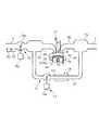
以下、図面を参照しながら、本発明の好ましい実施形態を詳細に説明する。図1は、本発明を適用した内燃機関(以下「エンジン」という)3を示す。このエンジン3は、車両(図示せず)に搭載された、例えば4気筒のガソリンエンジンである。各気筒3a(1つのみ図示)のピストン3bとシリンダヘッド3cとの間には、燃焼室3dが形成されている。 Hereinafter, preferred embodiments of the present invention will be described in detail with reference to the drawings. FIG. 1 shows an internal combustion engine (hereinafter referred to as “engine”) 3 to which the present invention is applied. The
各気筒3aには、吸気コレクタ部6aを有する吸気マニホルド6bを介して、吸気通路6が接続されるとともに、排気コレクタ部7aを有する排気マニホルド7bを介して、排気通路7が接続されている。吸気マニホルド6bには燃料噴射弁4(図2参照)が、シリンダヘッド3cには点火プラグ5(図2参照)が、それぞれ気筒3aごとに設けられている。燃料噴射弁4による燃料の噴射量・噴射時期、及び点火プラグ5の点火時期IGは、後述するECU2からの制御信号によって制御される。 An
また、各気筒3aには、吸気弁8及び排気弁9が設けられている。吸気弁8を駆動する吸気カムシャフト(図示せず)の一端部には、吸気カム位相可変機構15が設けられている。この吸気カム位相可変機構15は、エンジン3のクランクシャフト(図示せず)に対する吸気カムシャフトの相対的な位相(以下「吸気カム位相」という)CAINを無段階に変更するものであり、それにより、吸気弁8の開閉タイミングがクランクシャフトに対して無段階に変更(シフト)される。なお、吸気カム位相CAINは、吸気カム位相可変機構15のコントロールシャフト(図示せず)をVTCアクチュエータ15a(図2参照)で駆動することによって制御され、VTCアクチュエータ15aの動作は、ECU2からの制御信号によって制御される。 Each
吸気通路6の吸気コレクタ部6aよりも上流側には、スロットル弁機構10が設けられている。このスロットル弁機構10は、吸気通路6内に配置されたバタフライ式のスロットル弁10aと、スロットル弁10aを駆動するTHアクチュエータ10bを有する。スロットル弁10aの開度(以下「スロットル開度」という)θTHは、THアクチュエータ10bに供給される電流をECU2で制御することによって制御され、それにより、燃焼室3dに吸入される吸気量(新気量)GAIRが調整される。なお、このエンジン3の通常の運転状態では、燃焼室3dに供給される燃料と空気との混合気の目標空燃比AFCMDが理論空燃比に設定され、ストイキ燃焼が行われるとともに、加速運転時には、目標空燃比AFCMDは理論空燃比よりもリッチ側に制御される。 A
また、エンジン3には、燃焼室3dから排気通路7に排出された排ガスの一部を、EGRガスとして、吸気通路6に還流させるためのEGR装置11が設けられている。EGR装置11は、EGR通路12と、EGR通路12の途中に設けられたEGR弁機構13及びEGRクーラ14などで構成されている。EGR通路12は、排気通路7の排気コレクタ部7aと吸気通路6の吸気コレクタ部6aに接続されている。 Further, the
EGR弁機構13は、EGR通路12内に配置されたポペット式のEGR弁13aと、EGR弁13aを駆動するEGRアクチュエータ13bを有する。EGR弁13aのリフト量(以下「EGR弁開度」という)LEGRは、EGRアクチュエータ13bに供給される電流をECU2で制御することによって制御され、それにより、吸気通路6に還流するEGR量GEGRが調整される。EGRクーラ14は、EGR弁13aの上流側に配置されており、エンジン3の冷却水を利用し、高温のEGRガスを冷却する。 The
エンジン3のクランクシャフトには、クランク角センサ20が設けられている(図2参照)。クランク角センサ20は、クランクシャフトの回転に伴い、所定クランク角(例えば30°)ごとに、パルス信号であるCRK信号をECU2に出力する。ECU2は、このCRK信号に基づき、エンジン3の回転数(以下「エンジン回転数」という)NEを算出する。また、ECU2には、アクセル開度センサ21(図2参照)から、車両のアクセルペダル(図示せず)の操作量(以下「アクセル開度」という)APを表す検出信号が入力される。 A
また、吸気通路6のスロットル10aよりも上流側には、大気圧センサ22及び吸気温センサ23が設けられている。大気圧センサ22は大気圧PAを検出し、吸気温センサ23は吸気通路6を流れる吸気の温度(以下「吸気温」という)TAを検出し、それらの検出信号はECU2に出力される。 An
さらに、エンジン3のシリンダブロック3eには、エンジン3の冷却水の温度(以下「エンジン水温」という)TWを検出する水温センサ24と、ノッキングの発生状態を検出するノックセンサ25が設けられており、それらの検出信号はECU2に出力される。 Further, the
ECU2は、CPU、RAM、ROM及びI/Oインターフェース(いずれも図示せず)などから成るマイクロコンピュータで構成されている。ECU2は、前述した各種のセンサ20〜25の検出信号などに応じて、エンジン3の運転状態を判別するとともに、判別した運転状態に応じて、エンジン3の燃料噴射及び点火時期IGの制御や、吸気量GAIR及びEGR量GEGRを制御する吸気制御などを実行する。 The
本実施形態では、この吸気制御として、アクセル開度APなどに応じてエンジン3の目標トルクTRQCMDを設定するとともに、この目標トルクTRQCMDなどに応じて、目標吸気量GAIRCMD及び目標EGR量GEGRCMDを設定する。また、これらの目標吸気量GAIRCMD及び目標EGR量GEGRCMDにそれぞれ基づいて、スロットル開度θTH及びEGR弁開度LEGRのそれぞれの目標値である目標スロットル開度θTHCMD及び目標EGR弁開度LEGRCMDを設定し、さらにそれらに基づいてスロットル弁10a及びEGR弁13aを駆動することによって、吸気量GAIR及びEGR量GEGRが制御される。 In the present embodiment, as the intake control, the target torque TRQCMD of the
本実施形態では、ECU2が、最大吸気量算出手段、仮吸気量設定手段、推定トルク算出手段、仮吸気量−推定トルク関係設定手段、目標吸気量設定手段、仮目標スロットル開度算出手段、及び目標スロットル開度設定手段に相当する。 In the present embodiment, the
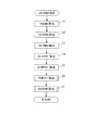
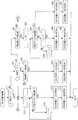
図3は、ECU2で実行される、目標吸気量GAIRCMDの設定処理のメインフローを示す。本処理は、所定時間ごとに繰り返し実行される。 FIG. 3 shows a main flow of the target intake air amount GAIRCMD setting process executed by the
本処理ではまず、ステップ1(「S1」と図示。以下同じ)において、検出されたアクセル開度AP及びエンジン回転数NEに応じ、所定のTRQCMDマップ(図示せず)を検索することによって、エンジン3の目標トルクTRQCMDを算出する。このTRQCMDマップでは、目標トルクTRQCMDは、アクセル開度APにほぼ比例するように設定されている。 In this process, first, in step 1 (illustrated as “S1”, the same applies hereinafter), a predetermined TRQCMD map (not shown) is searched according to the detected accelerator pedal opening AP and engine speed NE, thereby the engine. 3 target torque TRQCMD is calculated. In this TRQCMD map, the target torque TRQCMD is set to be substantially proportional to the accelerator pedal opening AP.
次に、算出された目標トルクTRQCMD及びエンジン回転数NEに応じ、所定のCAINCMDマップ(図示せず)を検索することによって、目標吸気カム位相CAINCMDを算出する(ステップ2)。このCAINCMDマップでは、目標吸気カム位相CAINCMDは、目標トルクTRQCMDが大きいほど、より進角側に設定されている。 Next, a target intake cam phase CAINCMD is calculated by searching a predetermined CAINCMD map (not shown) according to the calculated target torque TRQCMD and engine speed NE (step 2). In this CAINCMD map, the target intake cam phase CAINCMD is set to a more advanced side as the target torque TRQCMD is larger.
次に、算出された目標吸気カム位相CAINCMD及びエンジン回転数NEに応じ、所定のGAIRMAXマップを検索することによって、最大吸気量GAIRMAXを算出する(ステップ3)。この最大吸気量GAIRMAXは、そのときのエンジン3の運転状態において燃焼室3dに吸入することが可能な最大の吸気量に相当する。 Next, the maximum intake air amount GAIRMAX is calculated by searching a predetermined GAIRMAX map according to the calculated target intake cam phase CAINCMD and the engine speed NE (step 3). This maximum intake air amount GAIRMAX corresponds to the maximum intake air amount that can be sucked into the
次に、算出された最大吸気量GAIRMAXを用い、次式(1)によって複数の仮吸気量GAIRPRVi(i=1〜m)を算出する(ステップ4)。
GAIRPRVi=(GAIRMAX/m)×i ・・・(1)
この式(1)から明らかなように、仮吸気量GAIRPRViは、最大吸気量GAIRMAXを等間隔で分割したm個の吸気量によって構成されている。算出された複数の仮吸気量GAIRPRViは、ECU2のRAMの所定の記憶領域に記憶される。Next, using the calculated maximum intake air amount GAIRMAX, a plurality of temporary intake air amounts GAIRPRVi (i = 1 to m) are calculated by the following equation (1) (step 4).
GAIRPRVi = (GAIRMAX / m) × i (1)
As is apparent from the equation (1), the temporary intake air amount GAIRPRVi is composed of m intake air amounts obtained by dividing the maximum intake air amount GAIRMAX at equal intervals. The calculated plurality of provisional intake air amounts GAIRPRVi are stored in a predetermined storage area of the
次に、複数の仮吸気量GAIRPRViの各々、目標吸気カム位相CAINCMD及びエンジン回転数NEに応じ、所定のGEGRPRVマップ(図示せず)を検索することによって、複数の仮EGR量GEGRPRViをそれぞれ算出する(ステップ5)。このGEGRPRVマップは、仮吸気量GAIRPRV、目標吸気カム位相CAINCMD及びエンジン回転数NEに対して最適な燃費が得られるEGR量を、仮EGR量GEGRPRVとして設定したものである。 Next, a plurality of provisional EGR amounts GEGRPRVi are calculated by searching a predetermined GEGRPRV map (not shown) according to each of the plurality of provisional intake air amounts GAIRPRVi, the target intake cam phase CAINCMD and the engine speed NE. (Step 5). This GEGRPRV map is obtained by setting an EGR amount that provides optimum fuel consumption with respect to the temporary intake air amount GAIRPRV, the target intake cam phase CAINCMD, and the engine speed NE as a temporary EGR amount GEGRPRV.
なお、車両が高地条件にあるなどの理由から、EGR弁13aの上流側との差圧を確保するために吸気圧が制限される場合には、仮EGR量GEGRPRViは適宜、減少側に補正される。算出された複数の仮EGR量GEGRPRViは、仮吸気量GAIRPRViに対応させて、RAMの所定の記憶領域に記憶される。 When the intake pressure is limited in order to ensure a differential pressure with the upstream side of the EGR valve 13a because the vehicle is in a high altitude condition, the temporary EGR amount GEGRPRVi is appropriately corrected to the decreasing side. The The plurality of calculated temporary EGR amounts GEGRPRVi are stored in a predetermined storage area of the RAM in correspondence with the temporary intake air amount GAIRPRVi.
次に、複数の仮吸気量GAIRPRViに対応する複数の推定トルクTRQESTiを算出する(ステップ6)。これらの推定トルクTRQESTiは、そのときのエンジン3の運転状態において、仮吸気量GAIRPRViの吸気がそれぞれ燃焼室3dに吸入されたと仮定したときにエンジン3から出力されると推定されるトルクであり、仮吸気量GAIRPRViごとに算出される。図4は、その算出処理のサブルーチンである。 Next, a plurality of estimated torques TRQESTi corresponding to a plurality of temporary intake air amounts GAIRPRVi are calculated (step 6). These estimated torques TRQESTi are torques that are estimated to be output from the
本処理では、まずステップ11において、仮吸気量GAIRPRViを指示するインデックス番号iを「1」にセットする。次に、図3のステップ4及び5でそれぞれ算出された仮吸気量GAIRPRViと仮EGR量GEGRPRViとの和を、仮総ガス量GGASPRViとして算出する(ステップ12)。 In this process, first, in
次に、算出された仮総ガス量GGASPRVi及びエンジン回転数NEに応じ、図6に示すPBAESTマップを検索することによって、推定吸気圧PBAESTiを算出する(ステップ13)。図6のPBAESTマップは、所定のエンジン回転数NEにおける、仮総ガス量GGASPRVと推定吸気圧PBAESTとの関係を示しており、推定吸気圧PBAESTは、仮総ガス量GGASPRVに比例するように設定されている。 Next, the estimated intake pressure PBAESTi is calculated by searching the PBAEST map shown in FIG. 6 according to the calculated provisional total gas amount GGASPPRVi and the engine speed NE (step 13). The PBAEST map in FIG. 6 shows the relationship between the provisional total gas amount GGASPPRV and the estimated intake pressure PBAEST at a predetermined engine speed NE, and the estimated intake pressure PBAEST is set to be proportional to the provisional total gas amount GGASPPRV. Has been.
次に、点火時期IGのMBT(Minimum Spark Advance for Best Torque)からの推定リタード量IGRTDESTiを算出する(ステップ14)。図5は、その算出処理のサブルーチンである。本処理では、まずステップ21において、上記ステップ13で算出された推定吸気圧PBAESTi及びエンジン回転数NEに応じ、所定のIGRTDBASEマップ(図示せず)を検索することによって、推定リタード量の基本値IGRTDBASEiを算出する。このIGRTDBASEマップでは、基本値IGRTDBASEは、推定吸気圧PBAESTが高いほど、ノッキングが発生しやすくなるため、より大きな値に、すなわちより遅角側に設定されている。 Next, an estimated retard amount IGRTDESTi from the ignition timing IG from MBT (Minimum Spark Advance for Best Torque) is calculated (step 14). FIG. 5 is a subroutine for the calculation process. In this process, first, in
次に、検出されたエンジン水温TWに応じて、点火時期IGの水温補正量IGTWを算出する(ステップ22)とともに、検出された吸気温TAに応じて、点火時期IGの吸気温補正量IGTAを算出する(ステップ23)。また、ノックセンサ25で検出されたノッキングの発生状態に応じて、点火時期IGのノック補正量IGKNOCKを算出する(ステップ24)。そして、ステップ21で算出された推定リタード量の基本値IGRTDBASEiに、上記の3つの補正量IGTW、IGTA及びIGKNOCKを加算することによって、点火時期IGの推定リタード量IGRTDESTiを算出し(ステップ25)、本処理を終了する。 Next, a water temperature correction amount IGTW of the ignition timing IG is calculated according to the detected engine water temperature TW (step 22), and an intake air temperature correction amount IGTA of the ignition timing IG is calculated according to the detected intake air temperature TA. Calculate (step 23). Further, a knock correction amount IGKNOCK of the ignition timing IG is calculated according to the knocking occurrence state detected by the knock sensor 25 (step 24). Then, the estimated retard amount IGRTDESTi of the ignition timing IG is calculated by adding the above three correction amounts IGTW, IGTA, and IGKNOCK to the basic value IGRTDBASEi of the estimated retard amount calculated in step 21 (step 25). This process ends.
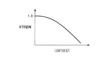
図4に戻り、前記ステップ14に続くステップ15では、算出された推定リタード量IGRTDESTi及びエンジン回転数NEに応じ、図7に示すKTRQDNマップを検索することによって、MBT燃焼時を基準とする推定トルクダウン率KTRQDNiを算出する。図7のPBAESTマップは、所定のエンジン回転数NEにおける、推定リタード量IGRTDESTと推定トルクダウン率KTRQDNとの関係を示しており、推定トルクダウン率KTRQDNは、推定リタード量IGRTDESTが大きいほど、エンジン3の燃焼効率が低下し、出力トルクが低下するため、より小さな値に設定されている。 Returning to FIG. 4, in
次に、仮吸気量GAIRPRVi及び上記の推定トルクダウン率KTRQDNiなどを用い、次式(2)によって、推定トルクTRQESTiを算出する(ステップ16)。
TRQESTi=GAIRPRVi×KTRQDNi×KGATRQ−TRQFR ・・・(2)
ここで、右辺のKGATRQは、ストイキ・MBT燃焼時における、吸気量GAIRをエンジン3の出力トルクに換算するための所定の換算係数であり、TRQFRは、エンジン3でのトルク損失となる所定のフリクションである。Next, the estimated torque TRQESTi is calculated by the following equation (2) using the temporary intake air amount GAIRPRVi and the estimated torque down rate KTRQDNi (step 16).
TRQESTi = GAIRPRVi × KTRQDNi × KGATRQ−TRQFR (2)
Here, KGATRQ on the right side is a predetermined conversion coefficient for converting the intake air amount GAIR into the output torque of the
次に、算出された推定トルクTRQESTiを、仮吸気量GAIRPRViに対応させて、RAMの所定の記憶領域に記憶する(ステップ17)。また、今回のインデックス番号iが仮吸気量GAIRPRViのサンプル数mに等しいか否かを判別する(ステップ18)。この答がNOのときには、ステップ19においてインデックス番号iをインクリメントした後、前記ステップ12に戻り、ステップ12〜17による推定トルクTRQESTiの算出処理を繰り返す。そして、すべての仮吸気量GAIRPRViに対して推定トルクTRQESTiの算出が完了すると、ステップ18の答がYESになるのに応じて、本処理を終了する。 Next, the calculated estimated torque TRQESTi is stored in a predetermined storage area of the RAM in correspondence with the temporary intake air amount GAIRPRVi (step 17). Further, it is determined whether or not the current index number i is equal to the number of samples m of the temporary intake air amount GAIRPRVi (step 18). When the answer is NO, after the index number i is incremented in
以上の算出処理により、すべての仮吸気量GAIRPRViに対し、そのときのエンジン3の運転状態に応じて推定された推定リタード量IGRTDESTiなどを反映した推定トルクTRQESTiがそれぞれ算出され、仮吸気量GAIRPRViに対応して記憶される。これにより、m個の仮吸気量GAIRPRVと推定トルクTRQESTとの組合せから成る、仮吸気量GAIRPRViと推定トルクTRQESTiとの関係(以下「仮吸気量−推定トルク関係」という)が設定される。 With the above calculation processing, the estimated torque TRQESTi reflecting the estimated retard amount IGRTDESTi estimated according to the operating state of the
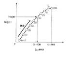
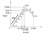
図8〜図11はそれぞれ、上記のように設定された仮吸気量−推定トルク関係をプロットすることによって得られた推定トルク特性線を表しており、互いに異なる4つの特性パターンを示す。図8に示す第1パターンは、仮吸気量GAIRPRVが増加するにつれて、推定トルクTRQESTが単純に増加する通常のパターン(単調増加パターン)である。 8 to 11 show estimated torque characteristic lines obtained by plotting the temporary intake air amount-estimated torque relationship set as described above, and show four different characteristic patterns. The first pattern shown in FIG. 8 is a normal pattern (monotonically increasing pattern) in which the estimated torque TRQEST simply increases as the temporary intake air amount GAIRPRV increases.
図9に示す第2パターンは、仮吸気量GAIRPRVが増加するにつれて、推定トルクTRQESTが極大値まで増加する一方、この極大点PMAXを過ぎた後には、ノッキングの抑制のために推定リタード量IGRTDESTが増大することなどに起因して、推定トルクTRQESTが低下する(落ち込む)パターン(2次曲線パターン)である。 In the second pattern shown in FIG. 9, the estimated torque TRQEST increases to a maximum value as the temporary intake air amount GAIRPRV increases. On the other hand, after the maximum point PMAX is passed, the estimated retard amount IGRTDEST is reduced to suppress knocking. This is a pattern (secondary curve pattern) in which the estimated torque TRQEST decreases (decreases) due to an increase or the like.
図10に示す第3パターンは、第2パターンの変形パターンというべきものであり、第2パターンのような推定トルクTRQESTの明確な極大点が現れず、推定トルクTRQESTが、仮吸気量GAIRPRVの増加に伴って非増加点PNINCまで増加した後、仮吸気量GAIRPRVが増加しても、増加せずにほぼ一定の状態になり、その後に低下するパターンである。 The third pattern shown in FIG. 10 should be a deformation pattern of the second pattern, and no clear maximum point of the estimated torque TRQEST like the second pattern appears, and the estimated torque TRQEST increases the temporary intake air amount GAIRPRV. With this, after increasing to the non-increasing point PNINC, even if the provisional intake air amount GAIRPRV increases, it does not increase but becomes a substantially constant state and then decreases.
また、図11に示す第4パターンは、上記第2パターンと同様に推定トルクTRQESTが極大点PMAXを境として低下した後、推定リタード量IGRTDESTが燃焼を良好に維持するために制限されることなどに起因して、推定トルクTRQESTが再度、増加に転じ、極大点PMAXに等しい再増加点PRINCを超えて増加するパターン(3次曲線パターン)である。 Further, in the fourth pattern shown in FIG. 11, the estimated retard amount IGRTDEST is limited in order to maintain good combustion after the estimated torque TRQEST is lowered at the maximum point PMAX as in the second pattern. Thus, the estimated torque TRQEST starts to increase again and increases beyond the re-increase point PRINC equal to the maximum point PMAX (third-order curve pattern).
図3に戻り、ステップ6に続くステップ7では、設定された仮吸気量−推定トルク関係に基づいて、目標吸気量GAIRCMDを算出し、本処理を終了する。図12はその算出処理のサブルーチンを示す。 Returning to FIG. 3, in
本処理では、まずインデックス番号iを「1」にセットする(ステップ31)とともに、インデックス番号iに対応する推定トルクTRQESTi、すなわちこの場合には推定トルクTRQEST1が、前記ステップ1で設定された目標トルクTRQCMD以上であるか否かを判別する(ステップ32)。この答がNOのときには、インデックス番号iをインクリメントする(ステップ33)とともに、上記ステップ32の判別を繰り返す。このように、ステップ32における推定トルクTRQESTiの判別は、インデックス番号iの小さい側から、すなわち仮吸気量GAIRPRViの小さい側から順に実行される。 In this process, first, the index number i is set to “1” (step 31), and the estimated torque TRQESTi corresponding to the index number i, that is, the estimated torque TRQEST1 in this case, is the target torque set in
そして、ステップ32の答がYESで、推定トルクTRQESTi≧目標トルクTRQCMDの関係が成立したときには、このときの推定トルクTRQESTiに対応する仮吸気量GAIRPRViを選択し、目標吸気量GAIRCMDとして設定する(ステップ34)。また、この仮吸気量GAIRPRViに対応して記憶された仮EGR量GEGRPRViを、目標EGR量GEGRCMDとして設定し(ステップ35)、本処理を終了する。 If the answer to step 32 is YES and the relationship of estimated torque TRQESTi ≧ target torque TRQCMD is established, the temporary intake air amount GAIRPRVi corresponding to the estimated torque TRQESTi at this time is selected and set as the target intake air amount GAIRCMD (step) 34). Further, the temporary EGR amount GEGRPRVi stored in correspondence with the temporary intake air amount GAIRPRVi is set as the target EGR amount GEGRCMD (step 35), and this process is terminated.
以上のように算出された目標吸気量GAIRCMD及び目標EGR量GEGRCMDにそれぞれ基づいて、スロットル開度θTH及びEGR弁開度LEGRの目標値が設定され、さらにそれらに基づいてスロットル弁10a及びEGR弁13aが駆動されることで、吸気量GAIRが目標吸気量GAIRCMDになるように制御され、EGR量GEGRが目標EGR量GEGRCMDになるように制御される。 Based on the target intake air amount GAIRCMD and the target EGR amount GEGRCMD calculated as described above, target values of the throttle opening θTH and the EGR valve opening LEGR are set, and further, based on them, the
以上のように、本実施形態によれば、最大吸気量GAIRMAXを等分割したm個の仮吸気量GAIRPRViと、各仮吸気量GAIRPRViの吸気が燃焼室3dに吸入されたと仮定したときにエンジン3から出力されるm個の推定トルクTRQESTiとの関係を、仮吸気量−推定トルク関係としてあらかじめ設定する。そして、そのような既定の仮吸気量−推定トルク関係に基づき、仮吸気量GAIRPRViの小さい側から順に、推定トルクTRQESTiが目標トルクTRQCMD以上になる仮吸気量GAIRPRViを検索し、目標吸気量QAIRCMDとして設定する(図12のステップ31〜34)。 As described above, according to the present embodiment, it is assumed that the
したがって、1つの目標トルクTRQCMDに対して、それを達成する吸気量の複数の解が存在する場合、例えば推定トルク特性線の特性パターンが図9〜図11に示す第2〜第4パターンの場合においても、推定トルクTRQESTが目標トルクTRQCMDに一致又は近似する最小の仮吸気量GAIRPRVを、ハンチングを生じることなく確実に選択することができる。そして、選択された最小の仮吸気量GAIRPRVを目標吸気量GAIRCMDとして設定するので、燃費を向上させることができる。また、そのような最小の仮吸気量GAIRPRVが求められた時点で、仮吸気量GAIRPRViの検索を終了し、それ以上の検索処理は行わないので、演算負荷を軽減することができる。 Therefore, when there are a plurality of solutions of the intake air amount that achieves one target torque TRQCMD, for example, when the characteristic pattern of the estimated torque characteristic line is the second to fourth patterns shown in FIGS. The minimum provisional intake air amount GAIRPRV at which the estimated torque TRQEST matches or approximates the target torque TRQCMD can be reliably selected without causing hunting. Since the selected minimum provisional intake air amount GAIRPRV is set as the target intake air amount GAIRCMD, fuel efficiency can be improved. Further, when such a minimum provisional intake air amount GAIRPRV is obtained, the search for the provisional intake air amount GAIRPRVi is terminated and no further search processing is performed, so that the calculation load can be reduced.
次に、図13〜図15を参照しながら、本発明の第2実施形態について説明する。本実施形態は、これまでに説明した第1実施形態と比較し、仮吸気量−推定トルク関係を設定するまでの処理は同じであり、この関係に基づく目標吸気量GAIRCMDの算出処理が異なるものである。 Next, a second embodiment of the present invention will be described with reference to FIGS. Compared with the first embodiment described so far, the present embodiment has the same processing until the provisional intake air amount-estimated torque relationship is set, and the calculation processing of the target intake air amount GAIRCMD based on this relationship is different. It is.
図13は、この目標吸気量GAIRCMDの算出処理のメインフローを示す。本処理では、仮吸気量−推定トルク関係を表す推定トルク特性線の特性パターンが、前述した第1〜第4パターンのいずれに該当するかを判定し(ステップ41)、次に、判定された特性パターンに基づいて、目標吸気量GAIRCMDを検索する(ステップ42)。 FIG. 13 shows a main flow of processing for calculating the target intake air amount GAIRCMD. In this process, it is determined whether the characteristic pattern of the estimated torque characteristic line representing the temporary intake air amount-estimated torque relationship corresponds to the first to fourth patterns described above (step 41), and then determined. Based on the characteristic pattern, the target intake air amount GAIRCMD is searched (step 42).
図14は、上記ステップ41で実行される特性パターンの判定処理のサブルーチンを示す。本処理では、まずインデックス番号iを「1」にセットする(ステップ51)とともに、このインデックス番号iに対応する推定トルクTRQESTiよりも、その次位の推定トルクTRQESTi+1が大きいか否かを判別する(ステップ52)。この答がYESのときには、今回のインデックス番号iがサンプル数mから1を減じた値(m−1)に等しいか否かを判別する(ステップ53)。この答がNOのときには、インデックス番号iをインクリメントした(ステップ54)後、前記ステップ52に戻り、上記の判別を繰り返す。 FIG. 14 shows a subroutine of characteristic pattern determination processing executed in step 41 described above. In this process, first, the index number i is set to “1” (step 51), and it is determined whether or not the next estimated torque TRQESTi + 1 is larger than the estimated torque TRQESTi corresponding to the index number i (step 51). Step 52). If the answer is YES, it is determined whether or not the current index number i is equal to a value (m-1) obtained by subtracting 1 from the sample number m (step 53). When the answer is NO, after the index number i is incremented (step 54), the process returns to step 52 and the above determination is repeated.
そして、ステップ52の答がYESのまま、前記ステップ53の答がYES(i=m−1)になったとき、すなわち、隣り合ういずれの2つの仮吸気量GAIRPRVi、GAIRPRVi+1の間においても、推定トルクTRQESTi+1>推定トルクTRQESTiの関係が成立しているときには、推定トルク特性線の特性パターンが図8に示す第1パターンであると判定し、そのことを表すために、特性パターンフラグF_TRQPTを「1」にセットし(ステップ55)、本処理を終了する。 Then, when the answer to step 52 is YES and the answer to step 53 is YES (i = m−1), that is, between any two adjacent temporary intake air amounts GAIRPRVi and GAIRPRVi + 1. When the relationship of torque TRQESTi + 1> estimated torque TRQESTi is established, it is determined that the characteristic pattern of the estimated torque characteristic line is the first pattern shown in FIG. 8, and the characteristic pattern flag F_TRQPT is set to “1” in order to indicate that. "(Step 55), and this process is terminated.
一方、前記ステップ52の答がNOで、推定トルクTRQESTi+1≦推定トルクTRQESTiが成立したときには、このときの推定トルクTRQESTiが、仮吸気量GAIRPRVが増加しても推定トルクTRQESTが増加しなくなる非増加点(第2パターンにおける極大点PMAX、又は第3パターンにおける非増加点PNINC)に相当するとして、このときの推定トルクTRQESTiを制限トルクTRQLMTとして設定する(ステップ56)。また、対応する仮吸気量GAIRPRViを制限吸気量GAIRLMTとして、対応する仮EGR量GEGRPRViを制限EGR量GEGRLMTとして、それぞれ設定する(ステップ57、58)。 On the other hand, when the answer to step 52 is NO and the estimated torque TRQESTi + 1 ≦ the estimated torque TRQESTi is established, the estimated torque TRQESTi at this time does not increase the estimated torque TRQEST even if the temporary intake air amount GAIRPRV increases. Assuming that it corresponds to (maximum point PMAX in the second pattern or non-increase point PNINC in the third pattern), the estimated torque TRQESTi at this time is set as the limit torque TRQLMT (step 56). Further, the corresponding provisional intake air amount GAIRPRVi is set as the restriction intake air amount GAIRLMT, and the corresponding provisional EGR amount GEGRPRVi is set as the restriction EGR amount GEGRLMT (steps 57 and 58).
次に、インデックス番号iをインクリメントした(ステップ59)後、推定トルクTRQESTiが、上記ステップ56で設定された制限トルクTRQLMTよりも大きいか否かを判別する(ステップ60)。この答がNOのときには、インデックス番号iがサンプル数mに等しいか否かを判別する(ステップ61)。この答がNOのときには、ステップ59に戻り、インデックス番号iをインクリメントした後、上記ステップ60の判別を繰り返す。 Next, after the index number i is incremented (step 59), it is determined whether or not the estimated torque TRQESTi is larger than the limit torque TRQLMT set in step 56 (step 60). If the answer is NO, it is determined whether or not the index number i is equal to the sample number m (step 61). If the answer is NO, the process returns to step 59, and after incrementing the index number i, the determination in
そして、ステップ60の答がNOのまま、前記ステップ61の答がYES(i=m)になったとき、すなわち、非増加点よりも大きな仮吸気量GAIRPRVの範囲に、制限トルクTRQLMTを上回る推定トルクTRQESTが存在しないときには、推定トルク特性線の特性パターンが図9又は図10に示す第2又は第3パターンであると判定し、特性パターンフラグF_TRQPTを「2」にセットし(ステップ62)、本処理を終了する。 When the answer to step 60 is NO and the answer to step 61 is YES (i = m), that is, in the range of the temporary intake air amount GAIRPRV larger than the non-increase point, the estimation exceeds the limit torque TRQLMT. When the torque TRQEST does not exist, it is determined that the characteristic pattern of the estimated torque characteristic line is the second or third pattern shown in FIG. 9 or FIG. 10, and the characteristic pattern flag F_TRQPT is set to “2” (step 62). This process ends.
一方、前記ステップ60の答がYESで、推定トルクTRQESTi>制限トルクTRQLMTが成立したときには、推定トルク特性線上に再増加点PRINCが存在し、特性パターンが図11に示す第4パターンであると判定して、このときのインデックス番号iを再増加点番号Nとして記憶する(ステップ63)とともに、特性パターンフラグF_TRQPTを「3」にセットし(ステップ64)、本処理を終了する。 On the other hand, when the answer to step 60 is YES and the estimated torque TRQESTi> the limit torque TRQLMT is established, it is determined that the re-increase point PRINC exists on the estimated torque characteristic line and the characteristic pattern is the fourth pattern shown in FIG. Then, the index number i at this time is stored as the re-increase point number N (step 63), and the characteristic pattern flag F_TRQPT is set to “3” (step 64), and this process ends.
図15は、図13のステップ42で実行される、目標吸気量GAIRCMDの検索処理のサブルーチンを示す。本処理では、まずステップ71において、特性パターンフラグF_TRQPTが「1」であるか否かを判別する。この答がYESで、判定された推定トルク特性線の特性パターンが第1パターンのときには、第1実施形態における図12のステップ31〜35とまったく同じ処理をステップ72〜76において実行することによって、目標吸気量GAIRCMDなどを設定し、本処理を終了する。 FIG. 15 shows a subroutine for the target intake air amount GAIRCMD search process executed in step 42 of FIG. In this process, first, in
すなわち、インデックス番号iを「1」にセットした(ステップ72)後、推定トルクTRQESTiが目標トルクTRQCMD以上であるか否かを判別する(ステップ73)。この答がNOのときには、インデックス番号iをインクリメントする(ステップ74)とともに、ステップ73の判別を繰り返す。そして、その答がYESで、推定トルクTRQESTi≧目標トルクTRQCMDが成立したときに、そのときの仮吸気量GAIRPRViを目標吸気量GAIRCMDとして設定する(ステップ75)とともに、対応する仮EGR量GEGRPRViを目標EGR量GEGRCMDとして設定する(ステップ76)。これにより、第1実施形態と同様、仮吸気量GAIRPRViの検索を、その小さい側から順に行うことによって、目標トルクTRQCMDを達成する最小の仮吸気量GAIRPRViを容易かつ確実に選択し、目標吸気量QAIRCMDとして設定することができる。 That is, after setting the index number i to “1” (step 72), it is determined whether or not the estimated torque TRQESTi is equal to or greater than the target torque TRQCMD (step 73). When the answer is NO, the index number i is incremented (step 74) and the determination at step 73 is repeated. If the answer is YES and the estimated torque TRQESTi ≧ target torque TRQCMD is established, the temporary intake air amount GAIRPRVi at that time is set as the target intake air amount GAIRCMD (step 75), and the corresponding temporary EGR amount GEGRPRVi is set as the target. The EGR amount GEGRCMD is set (step 76). Thus, as in the first embodiment, the temporary intake air amount GAIRPRVi is searched in order from the smallest side, so that the minimum temporary intake air amount GAIRPRVi that achieves the target torque TRQCMD can be easily and reliably selected, and the target intake air amount. It can be set as QAIRCMD.
前記ステップ71の答がNOのときには、特性パターンフラグF_TRQPTが「2」であるか否かを判別する(ステップ77)。この答がYESで、特性パターンが第2又は第3パターンのときには、目標トルクTRQCMDが制限トルクTRQLMTよりも大きいか否かを判別する(ステップ78)。この答がNOで、目標トルクTRQCMD≦制限トルクTRQLMTのときには、前記ステップ72以降に進み、第1パターンの場合と同様、仮吸気量GAIRPRViの検索をその小さい側から順に行い、推定トルクTRQESTi≧目標トルクTRQCMDが成立したときの仮吸気量GAIRPRViを選択し、目標吸気量GAIRCMDとして設定する。 When the answer to step 71 is NO, it is determined whether or not the characteristic pattern flag F_TRQPT is “2” (step 77). If the answer is YES and the characteristic pattern is the second or third pattern, it is determined whether or not the target torque TRQCMD is larger than the limit torque TRQLMT (step 78). If the answer is NO and the target torque TRQCMD ≦ the limit torque TRQLMT, the process proceeds to step 72 and the subsequent steps, and as in the case of the first pattern, the temporary intake air amount GAIRPRVi is searched in order from the smaller side, and the estimated torque TRQESTi ≧ target The provisional intake air amount GAIRPRVi when the torque TRQCMD is established is selected and set as the target intake air amount GAIRCMD.
一方、前記ステップ78の答がYESで、目標トルクTRQCMD>制限トルクTRQLMTのときには、目標吸気量GAIRCMDを、図14のステップ57で設定された制限吸気量GAIRLMTに設定する(ステップ79)とともに、目標EGR量GEGRCMDを、ステップ58で設定された制限EGR量GEGRLMTに設定し(ステップ80)、本処理を終了する。 On the other hand, if the answer to step 78 is YES and the target torque TRQCMD is greater than the limit torque TRQLMT, the target intake air amount GAIRCMD is set to the limit intake air amount GAIRLMT set in
以上のように、特性パターンが第2又は第3パターンの場合において、推定トルクTRQESTの極大点PMAX又は非増加点PNINCに相当する制限トルクTRQLMTを上回る目標トルクTRQCMDが設定されたときには、目標吸気量GAIRCMDは、制限トルクTRQLMTに対応する制限吸気量GAIRLMTに制限される(図9及び図10のかっこ書き)。これにより、目標吸気量GAIRCMDが極大点PMAX又は非増加点PNINCを超えて設定されることがなくなり、エンジン3のトルクの増加に寄与しない余分な燃料の消費を有効に回避できるので、燃費を向上させることができる。 As described above, when the characteristic pattern is the second or third pattern, when the target torque TRQCMD exceeding the limit torque TRQLMT corresponding to the maximum point PMAX or the non-increasing point PNINC of the estimated torque TRQEST is set, the target intake air amount GAIRCMD is limited to a limited intake air amount GAIRLMT corresponding to the limit torque TRQLMT (in parentheses in FIGS. 9 and 10). As a result, the target intake air amount GAIRCMD is not set beyond the maximum point PMAX or the non-increasing point PNINC, and the consumption of excess fuel that does not contribute to the increase in the torque of the
また、特性パターンが極大点PMAXを有する第2パターンの場合には、極大点PMAXを超えて吸気量GAIRを増加させると、燃料が無駄に消費されるだけでなく、エンジン3のトルクが低下するので、上述した制限吸気量GAIRLMTによる目標吸気量GAIRCDの制限によって、エンジン3のトルクの低下を有効に回避でき、ドライバビリティを向上させることができる。 When the characteristic pattern is the second pattern having the maximum point PMAX, increasing the intake air amount GAIR beyond the maximum point PMAX not only wastes fuel but also reduces the torque of the
前記ステップ77の答がNOで、特性パターンが第4パターンのときには、前記ステップ78と同様、目標トルクTRQCMDが制限トルクTRQLMTよりも大きいか否かを判別する(ステップ81)。この答がNOで、目標トルクTRQCMD≦制限トルクTRQLMTのときには、前記ステップ72以降に進み、第1パターンの場合と同様、仮吸気量GAIRPRViの検索をその小さい側から順に行い、推定トルクTRQESTi≧目標トルクTRQCMDが成立したときの仮吸気量GAIRPRViを選択し、目標吸気量GAIRCMDとして設定する。 When the answer to step 77 is NO and the characteristic pattern is the fourth pattern, it is determined whether the target torque TRQCMD is larger than the limit torque TRQLMT, as in step 78 (step 81). If the answer is NO and the target torque TRQCMD ≦ the limit torque TRQLMT, the process proceeds to step 72 and the subsequent steps, and as in the case of the first pattern, the temporary intake air amount GAIRPRVi is searched in order from the smaller side, and the estimated torque TRQESTi ≧ target The provisional intake air amount GAIRPRVi when the torque TRQCMD is established is selected and set as the target intake air amount GAIRCMD.
上記ステップ81の答がYESで、目標トルクTRQCMD>制限トルクTRQLMTのときには、インデックス番号iを図14のステップ63で記憶した再増加点番号Nにセットした(ステップ82)後、推定トルクTRQESTiが目標トルクTRQCMD以上であるか否かを判別する(ステップ83)。この答がNOのときには、インデックス番号iがサンプル数mに等しいか否かを判別し(ステップ84)、その答がNOのときには、インデックス番号iをインクリメントした(ステップ85)後、ステップ83の判別を繰り返す。 If the answer to step 81 is YES and the target torque TRQCMD is greater than the limit torque TRQLMT, the index number i is set to the re-increase point number N stored in step 63 of FIG. 14 (step 82), and then the estimated torque TRQESTi is set to the target It is determined whether or not the torque is TRQCMD or more (step 83). If the answer is NO, it is determined whether or not the index number i is equal to the number of samples m (step 84). If the answer is NO, the index number i is incremented (step 85) and then the determination in
そして、ステップ83の答がYESで、推定トルクTRQESTi≧目標トルクTRQCMDが成立したときには、そのときの仮吸気量GAIRPRViを目標吸気量GAIRCMDとして設定する(ステップ86)とともに、対応する仮EGR量GEGRPRViを目標EGR量GEGRCMDとして設定し(ステップ87)、本処理を終了する。 If the answer to step 83 is YES and the estimated torque TRQESTi ≧ target torque TRQCMD is established, the temporary intake air amount GAIRPRVi at that time is set as the target intake air amount GAIRCMD (step 86), and the corresponding temporary EGR amount GEGRPRVi is set. The target EGR amount GEGRCMD is set (step 87), and this process is terminated.
一方、前記ステップ84の答がYES(i=m)になったとき、すなわち、再増加点PRINCよりも大きな仮吸気量GAIRPRVの範囲に、目標トルクTRQCMD以上の推定トルクTRQESTが存在しないときには、目標吸気量GAIRCMDを、最大吸気量GAIRMAXに相当する仮吸気量GAIRPRVmに設定する(ステップ88)とともに、目標EGR量GEGRCMDを仮EGR量GEGRPRVmに設定し(ステップ89)、本処理を終了する。 On the other hand, when the answer to step 84 is YES (i = m), that is, when there is no estimated torque TRQEST greater than or equal to the target torque TRQCMD in the range of the temporary intake air amount GAIRPRV larger than the reincrease point PRINC. The intake air amount GAIRCMD is set to the temporary intake air amount GAIRPRVm corresponding to the maximum intake air amount GAIRMAX (step 88), and the target EGR amount GEGRCMD is set to the temporary EGR amount GEGRPRVm (step 89), and this process is terminated.
以上のように、特性パターンが第4パターンの場合において、制限トルクTRQLMTを上回る目標トルクTRQCMDが設定されるとともに、再増加点PRINCよりも大きな仮吸気量GAIRPRVの範囲に、目標トルクTRQCMD以上の推定トルクTRQESTが存在するときには、目標吸気量GAIRCMDは、そのときの推定トルクTRQESTiに対応する仮吸気量GAIRPRViに設定される。これにより、目標トルクTRQCMDを達成する最小の仮吸気量GAIRPRViを適切に選択し、目標吸気量QAIRCMDとして設定することができる。 As described above, in the case where the characteristic pattern is the fourth pattern, the target torque TRQCMD exceeding the limit torque TRQLMT is set, and is estimated to be equal to or greater than the target torque TRQCMD within the range of the temporary intake air amount GAIRPRV larger than the reincrease point PRINC. When the torque TRQEST is present, the target intake air amount GAIRCMD is set to the provisional intake air amount GAIRPRVi corresponding to the estimated torque TRQESTi at that time. Thereby, the minimum temporary intake air amount GAIRPRVi that achieves the target torque TRQCMD can be appropriately selected and set as the target intake air amount QAIRCMD.
一方、上記の場合において、目標トルクTRQCMD以上の推定トルクTRQESTが存在しないときには、目標吸気量GAIRCMDを、最大吸気量GAIRMAXに相当する仮吸気量GAIRPRVmに設定する。これにより、車両の運転者の要求に可能な限り応えて、エンジン3から最大限のトルクを出力させることができる。 On the other hand, in the above case, when the estimated torque TRQEST equal to or greater than the target torque TRQCMD does not exist, the target intake air amount GAIRCMD is set to the temporary intake air amount GAIRPRVm corresponding to the maximum intake air amount GAIRMAX. Thereby, the maximum torque can be output from the
次に、図16を参照しながら、目標スロットル開度θTHCMDの設定処理について説明する。本処理は、これまでに説明した第1実施形態(図12)又は第2実施形態(図15)によって設定された目標吸気量GAIRCMDなどに応じて、目標スロットル開度θTHCMDを最終的に設定するものである。 Next, the setting process of the target throttle opening degree θTHCMD will be described with reference to FIG. This process finally sets the target throttle opening θTHCMD according to the target intake air amount GAIRCMD set by the first embodiment (FIG. 12) or the second embodiment (FIG. 15) described so far. Is.
本処理では、まずステップ91において、検出されたアクセル開度APが所定の全開開度APWOにほぼ等しいか否かを判別し、次いで、ステップ92において、エンジン3で燃焼する混合気の目標空燃比AFCMDが理論空燃比よりもリッチ側に設定されているか否かを判別する。これらの答がいずれもYESのときには、目標スロットル開度θTHCMDを所定の全開開度θTHWOに設定し(ステップ93)、本処理を終了する。 In this process, first, in
これにより、アクセル開度APが全開状態にあるときに、運転者の加速要求に応え、エンジン3から最大のトルクを出力させることによって、ドライバビリティを向上させることができる。この場合、目標空燃比AFCMDが理論空燃比よりもリッチ側に設定されることが条件になっていることで、増量された燃料の気化熱による燃焼室内の冷却効果により、ノッキングに対する余裕度が高くなるので、目標スロットル開度θTHCMDを全開開度θTHWOに設定しても、顕著なノッキングが発生するおそれはない。 Accordingly, drivability can be improved by outputting the maximum torque from the
一方、前記ステップ91又は92の答がNOのときには、図12又は図15の処理で設定された目標吸気量GAIRCMD及びエンジン回転数NEに応じ、所定のθTHCMDPRVマップ(図示せず)を検索することによって、スロットル開度θTHの仮の目標値である仮目標スロットル開度θTHCMDPRVを算出する(ステップ94)。 On the other hand, if the answer to step 91 or 92 is NO, a predetermined θTHCMDPRV map (not shown) is searched according to the target intake air amount GAIRCMD and the engine speed NE set in the processing of FIG. 12 or FIG. Thus, a temporary target throttle opening θTHCMDPRV, which is a temporary target value of the throttle opening θTH, is calculated (step 94).
次に、エンジン回転数NEに応じ、所定のθTHEFFマップ(図示せず)を検索することによって、スロットル弁10aの有効開度θTHEFFを算出する(ステップ95)。この有効開度θTHEFFは、スロットル弁10aの開度がそれ以上増加しても、エンジン3のトルクがほとんど増加しなくなる開度であり、例えばスロットル弁10aの全開時のエンジン3のトルクに対して所定の数%だけ低いトルクに相当する開度として定義される。 Next, an effective opening θTHEFF of the
次に、算出した仮目標スロットル開度θTHCMDPRVが有効開度θTHEFF以下であるか否かを判別する(ステップ96)。この答がYESで、θTHCMDPRV≦θTHEFFのときには、目標スロットル開度θTHCMDを仮目標スロットル開度θTHCMDPRVに設定し(ステップ97)、本処理を終了する。 Next, it is determined whether or not the calculated temporary target throttle opening θTHCMDPRV is equal to or smaller than the effective opening θTHEFF (step 96). If the answer is YES and θTHCMDPRV ≦ θTHEFF, the target throttle opening θTHCMD is set to the temporary target throttle opening θTHCMDPRV (step 97), and this process is terminated.
一方、ステップ96の答がNOで、θTHCMDPRV>θTHEFFのときには、目標スロットル開度θTHCMDを有効開度θTHEFFに制限して設定し(ステップ98)、本処理を終了する。これにより、有効開度θTHEFFを超えた範囲でのスロットル開度θTHのハンチングを防止できるとともに、スロットル弁10a及びTHアクチュエータ10bの寿命を延ばすことができる。 On the other hand, if the answer to step 96 is NO and θTHCMDPRV> θTHEFF, the target throttle opening degree θTHCMD is set to be limited to the effective opening degree θTHEFF (step 98), and this process ends. As a result, it is possible to prevent hunting of the throttle opening θTH in the range exceeding the effective opening θTHEFF, and to extend the lifetime of the
なお、本発明は、説明した実施形態に限定されることなく、種々の態様で実施することができる。例えば、実施形態では、目標トルクTRQCMDを達成する最小の仮吸気量GAIRPRVの検索を、仮吸気量GAIRPRViの小さい側から順に行っているが、これに限らず、仮吸気量−推定トルク関係の全体を先に検索し、それらの中から条件を満たす最小の仮吸気量GAIRPRViを選択してもよい。 In addition, this invention can be implemented in various aspects, without being limited to the described embodiment. For example, in the embodiment, the search for the minimum provisional intake air amount GAIRPRV that achieves the target torque TRQCMD is performed in order from the side where the provisional intake air amount GAIRPRVi is small. May be searched first, and the minimum provisional intake air amount GAIRPRVi satisfying the conditions may be selected from among them.
また、仮吸気量GAIRPRViの検索の結果、推定トルクTRQEST≧目標トルクTRQCMDが成立したときの仮吸気量GAIRPRViを、そのまま目標吸気量GAIRCMDとして設定しているが、目標トルクTRQCMDが推定トルクTRQESTiに一致せず、2つの推定トルクTRQESTiの間に位置するときには、それらの補間計算によって仮吸気量GAIRPRVを求めてもよい。また、実施形態では、スロットル弁10aの有効開度θTHEFFを、エンジン回転数NEに応じて設定しているが、これに代えて、一定の所定値に設定してもよい。 As a result of the search for the temporary intake air amount GAIRPRVi, the temporary intake air amount GAIRPRVi when the estimated torque TRQEST ≧ target torque TRQCMD is established is set as the target intake air amount GAIRCMD as it is, but the target torque TRQCMD matches the estimated torque TRQESTi. Instead, when it is located between the two estimated torques TRQESTi, the provisional intake air amount GAIRPRV may be obtained by their interpolation calculation. Further, in the embodiment, the effective opening degree θTHEFF of the
さらに、実施形態における仮吸気量GAIRPRViのサンプル数m(=10)はあくまで例示であり、増減してもよいことはもちろんである。サンプル数mを増やした場合には、目標トルクTRQCMDを達成する最小の仮吸気量GAIRPRViをさらにきめ細かく選択でき、その算出精度を高めることができる。 Furthermore, the sample number m (= 10) of the temporary intake air amount GAIRPRVi in the embodiment is merely an example, and it goes without saying that the number may be increased or decreased. When the number of samples m is increased, the minimum provisional intake air amount GAIRPRVi that achieves the target torque TRQCMD can be selected more finely, and the calculation accuracy can be increased.
また、実施形態に示した、最大吸気量GAIRMAX、推定リタード量IGRTDESTや推定トルクTRQESTなどの各算出手法は、あくまで例示であり、他の適当な手法を採用してもよいことはもちろんである。 Further, the calculation methods such as the maximum intake air amount GAIRMAX, the estimated retard amount IGRTDEST, and the estimated torque TRQEST shown in the embodiment are merely examples, and other appropriate methods may be adopted.
さらに、実施形態は、本発明を車両用のガソリンエンジンに適用した例であるが、本発明は、これに限らず、ガソリンエンジン以外のディーゼルエンジンなどの各種のエンジンに適用することができる。また、車両用以外のエンジン、例えば、クランクシャフトを鉛直に配置した船外機などのような船舶推進機用エンジンにも適用可能である。その他、本発明の趣旨の範囲内で、細部の構成を適宜、変更することが可能である。 Furthermore, although embodiment is an example which applied this invention to the gasoline engine for vehicles, this invention is not restricted to this, It can apply to various engines, such as diesel engines other than a gasoline engine. Further, the present invention can also be applied to engines other than those for vehicles, for example, marine vessel propulsion engines such as outboard motors having a crankshaft arranged vertically. In addition, it is possible to appropriately change the detailed configuration within the scope of the gist of the present invention.
2 ECU(最大吸気量算出手段、仮吸気量設定手段、推定トルク算出手段、仮吸気 量−推定トルク関係設定手段、目標吸気量設定手段、仮目標スロットル 開度算出手段、目標スロットル開度設定手段)
3 エンジン(内燃機関)
3d 燃焼室
10a スロットル弁
NE エンジン回転数(内燃機関の運転状態)
TA 吸気温(内燃機関の運転状態)
TW エンジン水温(内燃機関の運転状態)
CAINCMD 目標吸気カム位相(内燃機関の運転状態)
GAIR 吸気量
TRQCMD 目標トルク
GAIRCMD 目標吸気量
GAIRMAX 最大吸気量
GAIRPRVi 複数の仮吸気量
TRQESTi 複数の推定トルク
θTH スロットル開度(スロットル弁の開度)
θTHCMDPRV 仮目標スロットル開度
θTHEFF 有効開度
θTHCMD 目標スロットル開度2 ECU (maximum intake air amount calculating means, temporary intake air amount setting means, estimated torque calculating means, temporary intake air amount-estimated torque relationship setting means, target intake air amount setting means, temporary target throttle opening degree calculating means, target throttle opening degree setting means )
3 Engine (Internal combustion engine)
NE engine speed (operating condition of internal combustion engine)
TA Intake temperature (internal combustion engine operating condition)
TW engine water temperature (operating condition of internal combustion engine)
CAINCMD target intake cam phase (operating state of internal combustion engine)
GAIR Intake Amount TRQCMD Target Torque GAIRCMD Target Intake Amount GAIRMAX Maximum Intake Amount GAIRPRVi Multiple Temporary Intakes TRQESTi Multiple Estimated Torques
θTH Throttle opening (throttle valve opening)
θTHCMDPRV Temporary target throttle opening θTHEFF Effective opening θTHCMD Target throttle opening
Claims (3)
Translated fromJapanese前記内燃機関の運転状態に基づいて、前記燃焼室に吸入可能な最大の吸気量を、最大吸気量として算出する最大吸気量算出手段と、
値0から前記算出された最大吸気量までの吸気量の範囲内で、互いに異なる複数の仮吸気量を設定する仮吸気量設定手段と、
前記内燃機関の運転状態に基づいて、前記設定された複数の仮吸気量の吸気がそれぞれ燃焼室に吸入されたと仮定したときに前記内燃機関から出力されると推定されるトルクを、複数の推定トルクとして算出する推定トルク算出手段と、
前記複数の仮吸気量と前記算出された複数の推定トルクとの関係である仮吸気量−推定トルク関係を設定する仮吸気量−推定トルク関係設定手段と、
当該設定された仮吸気量−推定トルク関係から、前記推定トルクが前記目標トルクに一致又は近似する最小の仮吸気量を選択し、前記目標吸気量として設定する目標吸気量設定手段と、
を備えることを特徴とする内燃機関の吸気制御装置。An intake control device for an internal combustion engine that sets a target intake air amount according to a target torque of the internal combustion engine and controls the intake air amount based on the set target intake air amount,
Maximum intake air amount calculating means for calculating, as a maximum intake air amount, the maximum intake air amount that can be sucked into the combustion chamber based on the operating state of the internal combustion engine;
Temporary intake air amount setting means for setting a plurality of different temporary intake air amounts within a range of intake air amount from a value of 0 to the calculated maximum intake air amount;
Based on the operating state of the internal combustion engine, a plurality of estimated torques that are estimated to be output from the internal combustion engine when it is assumed that intake air of the set plurality of temporary intake air amounts are respectively drawn into the combustion chamber Estimated torque calculating means for calculating as torque;
A temporary intake air amount-estimated torque relationship setting means for setting a temporary intake air amount-estimated torque relationship which is a relationship between the plurality of temporary intake air amounts and the calculated plurality of estimated torques;
A target intake air amount setting means for selecting a minimum temporary intake air amount in which the estimated torque matches or approximates the target torque from the set temporary intake air amount-estimated torque relationship, and setting the target intake air amount as the target intake air amount;
An intake control device for an internal combustion engine, comprising:
当該算出された仮目標スロットル開度が、前記スロットル弁の開度がそれ以上増加しても前記内燃機関のトルクがほとんど増加しなくなる開度である前記スロットル弁の有効開度以下のときに、前記スロットル弁の開度の最終的な目標値である目標スロットル開度を前記仮目標スロットル開度に設定し、前記仮目標スロットル開度が前記有効開度よりも大きいときに、前記目標スロットル開度を前記有効開度に制限して設定する目標スロットル開度設定手段と、をさらに備えることを特徴とする、請求項1又は2に記載の内燃機関の吸気制御装置。A temporary target throttle opening calculating means for calculating a temporary target throttle opening, which is a temporary target value of the throttle valve opening for adjusting the intake air amount, according to the target intake air amount;
When the calculated temporary target throttle opening is equal to or less than the effective opening of the throttle valve, which is an opening at which the torque of the internal combustion engine hardly increases even when the opening of the throttle valve is further increased, A target throttle opening that is a final target value of the throttle valve opening is set to the temporary target throttle opening, and the target throttle opening is established when the temporary target throttle opening is larger than the effective opening. The intake control device for an internal combustion engine according to claim 1 or 2, further comprising target throttle opening setting means for setting a degree by limiting the degree to the effective opening.
Priority Applications (3)
| Application Number | Priority Date | Filing Date | Title |
|---|---|---|---|
| JP2012192281AJP5536160B2 (en) | 2012-08-31 | 2012-08-31 | Intake control device for internal combustion engine |
| US13/964,367US9284897B2 (en) | 2012-08-31 | 2013-08-12 | Intake control system for internal combustion engine |
| DE102013217195.1ADE102013217195A1 (en) | 2012-08-31 | 2013-08-28 | Inlet control system for internal combustion engine |
Applications Claiming Priority (1)
| Application Number | Priority Date | Filing Date | Title |
|---|---|---|---|
| JP2012192281AJP5536160B2 (en) | 2012-08-31 | 2012-08-31 | Intake control device for internal combustion engine |
Publications (2)
| Publication Number | Publication Date |
|---|---|
| JP2014047736A JP2014047736A (en) | 2014-03-17 |
| JP5536160B2true JP5536160B2 (en) | 2014-07-02 |
Family
ID=50098709
Family Applications (1)
| Application Number | Title | Priority Date | Filing Date |
|---|---|---|---|
| JP2012192281AExpired - Fee RelatedJP5536160B2 (en) | 2012-08-31 | 2012-08-31 | Intake control device for internal combustion engine |
Country Status (3)
| Country | Link |
|---|---|
| US (1) | US9284897B2 (en) |
| JP (1) | JP5536160B2 (en) |
| DE (1) | DE102013217195A1 (en) |
Families Citing this family (8)
| Publication number | Priority date | Publication date | Assignee | Title |
|---|---|---|---|---|
| JP5925641B2 (en)* | 2012-08-31 | 2016-05-25 | 本田技研工業株式会社 | Intake control device for internal combustion engine |
| JP5564543B2 (en)* | 2012-09-25 | 2014-07-30 | 本田技研工業株式会社 | Control device for internal combustion engine |
| JP6008884B2 (en)* | 2014-01-29 | 2016-10-19 | 本田技研工業株式会社 | Pump loss calculation device for internal combustion engine |
| JP6287963B2 (en)* | 2015-06-05 | 2018-03-07 | トヨタ自動車株式会社 | Internal combustion engine |
| NL2015384B1 (en)* | 2015-09-01 | 2017-03-27 | Daf Trucks Nv | System and method for detecting and counteracting diesel engine runaway. |
| JP6489376B2 (en)* | 2016-03-30 | 2019-03-27 | マツダ株式会社 | Engine control device |
| JP7380367B2 (en)* | 2020-03-24 | 2023-11-15 | トヨタ自動車株式会社 | engine control device |
| CN117647966B (en)* | 2023-11-17 | 2025-03-07 | 东风商用车有限公司 | A gas engine air system control parameter calibration method and a gas engine control method |
Family Cites Families (13)
| Publication number | Priority date | Publication date | Assignee | Title |
|---|---|---|---|---|
| JP2924246B2 (en)* | 1991-03-28 | 1999-07-26 | 三菱自動車工業株式会社 | Output control device for internal combustion engine |
| JPH11182299A (en) | 1997-12-15 | 1999-07-06 | Nissan Motor Co Ltd | Engine torque control device |
| JP3876609B2 (en)* | 2000-10-31 | 2007-02-07 | トヨタ自動車株式会社 | Idle rotation control device for internal combustion engine |
| JP4656984B2 (en)* | 2005-04-04 | 2011-03-23 | 本田技研工業株式会社 | Control device for internal combustion engine |
| JP2007218132A (en)* | 2006-02-15 | 2007-08-30 | Toyota Motor Corp | Control device for internal combustion engine |
| JP4335249B2 (en)* | 2006-12-04 | 2009-09-30 | 三菱電機株式会社 | Control device for internal combustion engine |
| JP4947012B2 (en)* | 2008-08-26 | 2012-06-06 | トヨタ自動車株式会社 | Control device for internal combustion engine |
| JP2010112214A (en)* | 2008-11-05 | 2010-05-20 | Toyota Motor Corp | Control device of internal combustion engine |
| JP4832542B2 (en) | 2009-03-18 | 2011-12-07 | 本田技研工業株式会社 | Control device for internal combustion engine |
| JP5043165B2 (en) | 2010-08-27 | 2012-10-10 | 本田技研工業株式会社 | Control device for internal combustion engine |
| JP5287818B2 (en)* | 2010-10-01 | 2013-09-11 | 三菱自動車工業株式会社 | Engine control device |
| JP5191523B2 (en)* | 2010-11-05 | 2013-05-08 | ヤマハ発動機株式会社 | Engine control device and engine control method for saddle riding type vehicle |
| JP5564543B2 (en)* | 2012-09-25 | 2014-07-30 | 本田技研工業株式会社 | Control device for internal combustion engine |
- 2012
- 2012-08-31JPJP2012192281Apatent/JP5536160B2/ennot_activeExpired - Fee Related
- 2013
- 2013-08-12USUS13/964,367patent/US9284897B2/ennot_activeExpired - Fee Related
- 2013-08-28DEDE102013217195.1Apatent/DE102013217195A1/ennot_activeCeased
Also Published As
| Publication number | Publication date |
|---|---|
| JP2014047736A (en) | 2014-03-17 |
| US9284897B2 (en) | 2016-03-15 |
| US20140060485A1 (en) | 2014-03-06 |
| DE102013217195A1 (en) | 2014-03-06 |
Similar Documents
| Publication | Publication Date | Title |
|---|---|---|
| JP5564543B2 (en) | Control device for internal combustion engine | |
| JP5536160B2 (en) | Intake control device for internal combustion engine | |
| JP5103459B2 (en) | Engine control device | |
| US9109528B2 (en) | Control system for internal combustion engine | |
| JP5433091B2 (en) | Control device for internal combustion engine | |
| US20090017987A1 (en) | Control Method and Control Device for Engine | |
| JP2008064032A (en) | Control device for internal combustion engine, control method, program for realizing the method, and recording medium recording the program | |
| US10550778B2 (en) | Control device for internal combustion engine | |
| US9322346B2 (en) | Ignition control device for internal combustion engine | |
| WO2014002189A1 (en) | Internal combustion engine control device | |
| US20190170071A1 (en) | Controller of internal combustion engine | |
| JP5925641B2 (en) | Intake control device for internal combustion engine | |
| JP5364636B2 (en) | Control device for internal combustion engine | |
| US20040163623A1 (en) | Ignition timing control apparatus for internal combustion engine | |
| JP7586313B2 (en) | EXHAUST RECIRCULATION CONTROL METHOD AND CONTROL DEVICE FOR INTERNAL COMBUSTION ENGINE | |
| JP5303349B2 (en) | EGR control device for internal combustion engine | |
| JP6432548B2 (en) | Engine control device | |
| JP2011144721A (en) | Ignition timing control device of internal combustion engine | |
| JP3738805B2 (en) | Control device for internal combustion engine | |
| JP6979315B2 (en) | Engine control unit | |
| JP2006307763A (en) | Knocking control device for internal combustion engine |
Legal Events
| Date | Code | Title | Description |
|---|---|---|---|
| TRDD | Decision of grant or rejection written | ||
| A01 | Written decision to grant a patent or to grant a registration (utility model) | Free format text:JAPANESE INTERMEDIATE CODE: A01 Effective date:20140401 | |
| A61 | First payment of annual fees (during grant procedure) | Free format text:JAPANESE INTERMEDIATE CODE: A61 Effective date:20140423 | |
| R150 | Certificate of patent or registration of utility model | Ref document number:5536160 Country of ref document:JP Free format text:JAPANESE INTERMEDIATE CODE: R150 | |
| LAPS | Cancellation because of no payment of annual fees |