JP5535061B2 - Compact scanning fiber device - Google Patents
Compact scanning fiber deviceDownload PDFInfo
- Publication number
- JP5535061B2 JP5535061B2JP2010502065AJP2010502065AJP5535061B2JP 5535061 B2JP5535061 B2JP 5535061B2JP 2010502065 AJP2010502065 AJP 2010502065AJP 2010502065 AJP2010502065 AJP 2010502065AJP 5535061 B2JP5535061 B2JP 5535061B2
- Authority
- JP
- Japan
- Prior art keywords
- actuator tube
- free end
- optical fiber
- end portion
- tube
- Prior art date
- Legal status (The legal status is an assumption and is not a legal conclusion. Google has not performed a legal analysis and makes no representation as to the accuracy of the status listed.)
- Active
Links
Images


Classifications
- A—HUMAN NECESSITIES
- A61—MEDICAL OR VETERINARY SCIENCE; HYGIENE
- A61B—DIAGNOSIS; SURGERY; IDENTIFICATION
- A61B1/00—Instruments for performing medical examinations of the interior of cavities or tubes of the body by visual or photographical inspection, e.g. endoscopes; Illuminating arrangements therefor
- A61B1/04—Instruments for performing medical examinations of the interior of cavities or tubes of the body by visual or photographical inspection, e.g. endoscopes; Illuminating arrangements therefor combined with photographic or television appliances
- A—HUMAN NECESSITIES
- A61—MEDICAL OR VETERINARY SCIENCE; HYGIENE
- A61B—DIAGNOSIS; SURGERY; IDENTIFICATION
- A61B1/00—Instruments for performing medical examinations of the interior of cavities or tubes of the body by visual or photographical inspection, e.g. endoscopes; Illuminating arrangements therefor
- A61B1/00064—Constructional details of the endoscope body
- A61B1/00071—Insertion part of the endoscope body
- A61B1/0008—Insertion part of the endoscope body characterised by distal tip features
- A—HUMAN NECESSITIES
- A61—MEDICAL OR VETERINARY SCIENCE; HYGIENE
- A61B—DIAGNOSIS; SURGERY; IDENTIFICATION
- A61B1/00—Instruments for performing medical examinations of the interior of cavities or tubes of the body by visual or photographical inspection, e.g. endoscopes; Illuminating arrangements therefor
- A61B1/00163—Optical arrangements
- A61B1/00165—Optical arrangements with light-conductive means, e.g. fibre optics
- A—HUMAN NECESSITIES
- A61—MEDICAL OR VETERINARY SCIENCE; HYGIENE
- A61B—DIAGNOSIS; SURGERY; IDENTIFICATION
- A61B1/00—Instruments for performing medical examinations of the interior of cavities or tubes of the body by visual or photographical inspection, e.g. endoscopes; Illuminating arrangements therefor
- A61B1/00163—Optical arrangements
- A61B1/00172—Optical arrangements with means for scanning
- A—HUMAN NECESSITIES
- A61—MEDICAL OR VETERINARY SCIENCE; HYGIENE
- A61B—DIAGNOSIS; SURGERY; IDENTIFICATION
- A61B1/00—Instruments for performing medical examinations of the interior of cavities or tubes of the body by visual or photographical inspection, e.g. endoscopes; Illuminating arrangements therefor
- A61B1/00163—Optical arrangements
- A61B1/00174—Optical arrangements characterised by the viewing angles
- A61B1/00183—Optical arrangements characterised by the viewing angles for variable viewing angles
- A—HUMAN NECESSITIES
- A61—MEDICAL OR VETERINARY SCIENCE; HYGIENE
- A61B—DIAGNOSIS; SURGERY; IDENTIFICATION
- A61B5/00—Measuring for diagnostic purposes; Identification of persons
- A61B5/0059—Measuring for diagnostic purposes; Identification of persons using light, e.g. diagnosis by transillumination, diascopy, fluorescence
- A61B5/0062—Arrangements for scanning
- G—PHYSICS
- G02—OPTICS
- G02B—OPTICAL ELEMENTS, SYSTEMS OR APPARATUS
- G02B23/00—Telescopes, e.g. binoculars; Periscopes; Instruments for viewing the inside of hollow bodies; Viewfinders; Optical aiming or sighting devices
- G02B23/24—Instruments or systems for viewing the inside of hollow bodies, e.g. fibrescopes
- G02B23/2476—Non-optical details, e.g. housings, mountings, supports
- G—PHYSICS
- G02—OPTICS
- G02B—OPTICAL ELEMENTS, SYSTEMS OR APPARATUS
- G02B23/00—Telescopes, e.g. binoculars; Periscopes; Instruments for viewing the inside of hollow bodies; Viewfinders; Optical aiming or sighting devices
- G02B23/24—Instruments or systems for viewing the inside of hollow bodies, e.g. fibrescopes
- G02B23/26—Instruments or systems for viewing the inside of hollow bodies, e.g. fibrescopes using light guides
- G—PHYSICS
- G02—OPTICS
- G02B—OPTICAL ELEMENTS, SYSTEMS OR APPARATUS
- G02B26/00—Optical devices or arrangements for the control of light using movable or deformable optical elements
- G02B26/08—Optical devices or arrangements for the control of light using movable or deformable optical elements for controlling the direction of light
- G02B26/10—Scanning systems
- G02B26/103—Scanning systems having movable or deformable optical fibres, light guides or waveguides as scanning elements
- A—HUMAN NECESSITIES
- A61—MEDICAL OR VETERINARY SCIENCE; HYGIENE
- A61B—DIAGNOSIS; SURGERY; IDENTIFICATION
- A61B5/00—Measuring for diagnostic purposes; Identification of persons
- A61B5/0059—Measuring for diagnostic purposes; Identification of persons using light, e.g. diagnosis by transillumination, diascopy, fluorescence
- A61B5/0082—Measuring for diagnostic purposes; Identification of persons using light, e.g. diagnosis by transillumination, diascopy, fluorescence adapted for particular medical purposes
- A61B5/0084—Measuring for diagnostic purposes; Identification of persons using light, e.g. diagnosis by transillumination, diascopy, fluorescence adapted for particular medical purposes for introduction into the body, e.g. by catheters
Landscapes
- Health & Medical Sciences (AREA)
- Life Sciences & Earth Sciences (AREA)
- Physics & Mathematics (AREA)
- Surgery (AREA)
- Optics & Photonics (AREA)
- Biomedical Technology (AREA)
- Veterinary Medicine (AREA)
- Biophysics (AREA)
- Pathology (AREA)
- Engineering & Computer Science (AREA)
- Nuclear Medicine, Radiotherapy & Molecular Imaging (AREA)
- Heart & Thoracic Surgery (AREA)
- Medical Informatics (AREA)
- Molecular Biology (AREA)
- Radiology & Medical Imaging (AREA)
- Animal Behavior & Ethology (AREA)
- General Health & Medical Sciences (AREA)
- Public Health (AREA)
- General Physics & Mathematics (AREA)
- Astronomy & Astrophysics (AREA)
- Mechanical Optical Scanning Systems (AREA)
- Endoscopes (AREA)
- Instruments For Viewing The Inside Of Hollow Bodies (AREA)
Description
Translated fromJapanese本発明の実施形態は、走査型ファイバ・デバイスに関する。具体的には、本発明の実施形態は、光ファイバのカンチレバー自由端部分の少なくとも一部分がアクチュエータ・チューブ内に配置される走査型ファイバ・デバイスに関し、並びにこのような走査型ファイバ・デバイスの製造及び使用方法に関する。 Embodiments of the invention relate to scanning fiber devices. In particular, embodiments of the present invention relate to scanning fiber devices in which at least a portion of the cantilever free end portion of an optical fiber is disposed within an actuator tube, and the manufacture and manufacture of such scanning fiber devices. Regarding usage.
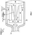
図1は、既知の走査型ファイバ・デバイス100の側断面図である。走査型ファイバ・デバイスはハウジング102を含む。ハウジング内には、圧電チューブ104が収められ、取付けカラー106によってハウジングに取り付けられる。光ファイバ108の一部分は、圧電チューブを通して挿入される。光ファイバのカンチレバー自由端部分110は、ハウジング内にあり、圧電チューブの遠位端に取り付けられる。カンチレバー自由端部分は可撓性であり、振動又は移動させることができる。圧電チューブはその上に電極112を有する。ワイヤ114が電極に電気的に結合される。電極を駆動して、光ファイバのカンチレバー自由端部分を1次元又は2次元的に振動又は別様に移動させるか又は走査することができる。 FIG. 1 is a cross-sectional side view of a known
断続線を用いて、光ファイバの自由端部分が移動できることを示す。光ファイバの移動により、関心領域の画像を取得することができる。例えば、走査型ファイバ・デバイスは、随意的なレンズ系を介して、走査パターン内の領域にわたって照射スポットを走査することができる。例えば、1つ又はそれ以上の光ファイバ又は光検知器により、後方散乱光を時系列で捕捉することができる。 It shows that the free end portion of the optical fiber can be moved using the interrupted line. An image of the region of interest can be acquired by moving the optical fiber. For example, a scanning fiber device can scan the illumination spot over an area in the scan pattern via an optional lens system. For example, backscattered light can be captured in time series by one or more optical fibers or photodetectors.
図示した走査型ファイバ・デバイスにおいては、光ファイバのカンチレバー自由端部分は、圧電チューブの端部に取り付けられることに注意されたい。カンチレバー自由端部分を圧電チューブの端部に取り付けることは、ハウジングの長さを特定の実施に望まれるよりも長くする必要があり得るという潜在的な欠点を有する可能性がある。具体的には、ハウジングの長さは、圧電チューブの長さ(L1)に光ファイバのカンチレバー自由端部分の長さ(L2)を加えた和よりも長くする必要がある可能性がある。これは、部分的には、圧電チューブの長さと光ファイバのカンチレバー自由端部分の長さがエンドツーエンドで一直線に並べられ、実質的に重ならないためである。 Note that in the illustrated scanning fiber device, the cantilever free end portion of the optical fiber is attached to the end of the piezoelectric tube. Attaching the cantilever free end portion to the end of the piezoelectric tube may have the potential disadvantage that the length of the housing may need to be longer than desired for a particular implementation. Specifically, the length of the housing may need to be longer than the sum of the length (L1) of the piezoelectric tube plus the length (L2) of the cantilever free end of the optical fiber. This is because, in part, the length of the piezoelectric tube and the length of the optical fiber cantilever free end are aligned end-to-end and do not substantially overlap.
一般に、ハウジングは、内部のコンポーネントに対して十分な機械的保護を与えるように比較的硬くする。特定の走査型ファイバ・デバイスの場合、例えば、操作性及び/又は窮屈な領域へのデバイスの挿入を容易にするために、遠位端の硬いハウジングの長さを短くする選択肢を有することが有益であり得る。 In general, the housing is relatively stiff to provide sufficient mechanical protection for the internal components. For certain scanning fiber devices, it is beneficial to have the option of reducing the length of the rigid housing at the distal end, for example, to facilitate handling and / or ease of insertion of the device into a tight area It can be.
本発明は、以下の説明及び本発明の実施形態を示すために用いられる添付の図面を参照することによって、最も良く理解することができる。 The invention can best be understood by referring to the following description and accompanying drawings that are used to illustrate embodiments of the invention.
以下の説明において、多くの特定の細部が示される。しかしながら、本発明の実施形態はこれらの特定の細部を用いずに実施できることが理解される。他の例では、周知の回路、構造体及び技術は、この説明の理解を不明瞭にしないように詳細には示されていない。 In the following description, numerous specific details are set forth. However, it is understood that embodiments of the invention may be practiced without these specific details. In other instances, well-known circuits, structures and techniques have not been shown in detail in order not to obscure the understanding of this description.
図2は、本発明の実施形態による、例示的な走査型ファイバ・デバイス220の側断面図である。走査型ファイバ・デバイスは、アクチュエータ・チューブ225、及び光ファイバ235のカンチレバー自由端部分230を含む。光ファイバのカンチレバー自由端部分は、アクチュエータ・チューブに結合された取付け端240、及びアクチュエータ・チューブによって動かされる自由端又は先端部245を有する。図示したように、本発明の実施形態においては、光ファイバのカンチレバー自由端部分の長さの少なくとも一部分は、アクチュエータ・チューブ内に配置され、アクチュエータ・チューブ内で振動又は移動することができる。この特定の例示的な走査型ファイバ・デバイスに示したように、本発明の実施形態においては、光ファイバのカンチレバー自由端部分の長さの実質的に全てをアクチュエータ・チューブ内に配置することができるが、このことは必須ではない。 FIG. 2 is a cross-sectional side view of an exemplary
本発明の種々の実施形態において、走査型ファイバ・デバイスは、走査型ファイバ内視鏡、走査型ファイバ・ボロスコープ、走査型ファイバ顕微鏡、又は他のタイプの走査型ファイバ・スコープ、走査型ファイバ・バーコード・リーダー、走査型ファイバ画像表示デバイス、又は当技術分野で既知の他の走査型ファイバ画像取得及び/又は表示デバイスの形態をとることができる。周知のように、内視鏡は、患者に挿入され、身体の管腔又は腔の内部を調べ、或いは別様に患者の内部を調べるのに用いることができる器具又はデバイスである。通常、用語「内部の」が省略され、「スコープ」と組み合された身体の管腔又は腔が、特定のタイプの器具を指すのに用いられる。適切なタイプの走査型ファイバ内視鏡の例には、それらに限定されないが、気管支鏡、結腸鏡、胃鏡、十二指腸鏡、S状結腸鏡、押込み直腸鏡、総胆管鏡、膀胱鏡、子宮鏡、喉頭鏡、鼻喉頭鏡、胸腔鏡、尿管鏡、関節鏡、腹腔鏡、腎臓鏡、耳鏡、鼻腔鏡、及びボロスコープが含まれる。内視鏡は、本明細書においては単に「スコープ」と呼ぶこともできる。 In various embodiments of the present invention, the scanning fiber device comprises a scanning fiber endoscope, a scanning fiber boroscope, a scanning fiber microscope, or other type of scanning fiber scope, scanning fiber scope. It can take the form of a bar code reader, a scanning fiber image display device, or other scanning fiber image acquisition and / or display device known in the art. As is well known, an endoscope is an instrument or device that can be inserted into a patient and used to examine the interior of a body lumen or cavity, or otherwise to examine the interior of a patient. Usually, the term “internal” is omitted, and a body lumen or cavity combined with a “scope” is used to refer to a particular type of instrument. Examples of suitable types of scanning fiber endoscopes include, but are not limited to, bronchoscopes, colonoscopes, gastroscopes, duodenoscopes, sigmoidoscopes, push-in rectoscopes, cholangioscopes, cystoscopes, hysteroscopes Laryngoscope, nasopharyngeal mirror, thoracoscope, ureteroscope, arthroscope, laparoscope, nephroscope, otoscope, nasal scope, and boroscope. An endoscope can also be simply referred to herein as a “scope”.
走査型ファイバ・デバイスはまた、ハウジング250を有する。ハウジングは、筐体の材料又はデバイスを表すことができる。前述のように、幾つかの実施において、ハウジングは、例えば、内部のコンポーネントに対して十分な機械的保護を与えるために、比較的硬くする傾向があり得る。例えば、患者に挿入される内視鏡又は他のデバイスの場合のような幾つかの実施においては、ハウジングを密封することができるが、これは、他の実施においては必要ではない。 The scanning fiber device also has a
ハウジング内には、アクチュエータ・チューブ225が配置される。アクチュエータ・チューブは、本明細書においては、一般には電気的な印加信号に応答して、後述の光ファイバのカンチレバー自由端部分を作動又は移動させることができる広い意味でのチューブであると解釈されたい。このチューブは、内部に光ファイバの少なくとも一部分を有する中空の一般には細長い本体とすることができる。一般に、このチューブは円形の断面を有することができるが、楕円形又は多角形の断面も場合によっては適切である。幾つかの実施形態において、このチューブは円筒形とすることができるが、他の実施形態においては、テーパ型或いは円錐形とすることができる。 An
本発明の実施形態において、アクチュエータ・チューブは、トランスデューサ・チューブを含むことができる。適切なトランスデューサ・チューブの例には、それらに限定されないが、圧電チューブ、電気活性ポリマー(EAP)チューブ、及び、光ファイバのカンチレバー自由端部分を作動又は移動させることができる他のトランスヂューサ材料のチューブが含まれる。適切なアクチュエータ・チューブの別の例は、必ずしもトランスデューサ型ではないが、例えば、1つ又はそれ以上の微小電気機械システム(MEMS)によって、或いは別の作動又はトランスデューサ型材料若しくはデバイスによって、或いは印加電界によってのように、他のコンポーネントによって作動させることができる材料のチューブである。適切な圧電チューブの例は、それらに限定されないが、ニュージャージー州、フェアフィールド所在のMorgan Technical Ceramics Sales、カナダ、オンタリオ州、コリングズウッド所在のSensor Technology Ltd.及びマサチューセッツ州、オーバーン所在のPI(Physik Instrumente)L.P.を含む幾つかの供給元から市販されている。 In embodiments of the invention, the actuator tube can include a transducer tube. Examples of suitable transducer tubes include, but are not limited to, piezoelectric tubes, electroactive polymer (EAP) tubes, and other transducer materials that can actuate or move the cantilever free end portion of an optical fiber. Tube is included. Other examples of suitable actuator tubes are not necessarily transducer-type, but are for example by one or more microelectromechanical systems (MEMS), or by another actuation or transducer-type material or device, or by an applied electric field Is a tube of material that can be actuated by other components. Examples of suitable piezoelectric tubes include, but are not limited to, Morgan Technical Ceramics Sales, Fairfield, New Jersey, and Sensor Technology Ltd., Collingswood, Ontario, Canada. And PI (Physik Instrument) L., Auburn, Massachusetts. P. Are commercially available from several sources including:
ハウジング内にはまた、光ファイバ235のカンチレバー自由端部分230が配置される。カンチレバー自由端部分は、取付け近位端240と、自由遠位端又は先端部245とを有する。光ファイバの自由遠位端又は先端部は、物理的に結合されておらず、アクチュエータ・チューブによって自由に動かされる。 Also disposed within the housing is a cantilever
「近位」という用語は、本明細書においては、走査型ファイバ・デバイスの図示されていない通常の部分255に最も近くなるデバイス又はそのコンポーネントの側(図の左側)を指すのに用いられる。例として、内視鏡の場合は、通常の部分は、光源及びアクチュエータ・チューブ用駆動電子回路を有するベース・ステーションへのケーブル及びコネクタを含むことができる。代替的に、別の例として、光源及び駆動電子回路並びに他の隋意的な通常のコンポーネントは、ハウジング内に直接組み込むことができる。「遠位」という用語は、本明細書においては、画像が取得され又は表示される表面に最も近くなるデバイス又はそのコンポーネントの側(図の右側)を指すのに用いられる。 The term “proximal” is used herein to refer to the side of the device or its component that is closest to the normal portion 255 (not shown) of the scanning fiber device (left side of the figure). By way of example, in the case of an endoscope, a typical part may include a cable and connector to a base station having a light source and drive electronics for an actuator tube. Alternatively, as another example, the light source and drive electronics and other arbitrary conventional components can be incorporated directly into the housing. The term “distal” is used herein to refer to the side of the device or its component that is closest to the surface from which an image is acquired or displayed (the right side of the figure).
取付け近位端は、アクチュエータ・チューブに物理的に結合される。図示したように、1つ又はそれ以上の実施形態において、取付け近位端は、アクチュエータ・チューブの近位端又は近位部分と物理的に結合させることができる。この物理的結合は、取付け端をアクチュエータ・チューブの近位端又は近位部分に、それらが一緒に動くように固着又は堅固に固定させる助けとなり得る。取付け端は、図示したように取付け端の右に水平方向に突き出るカンチレバー自由端部分を支持する。 The proximal proximal end is physically coupled to the actuator tube. As shown, in one or more embodiments, the attachment proximal end can be physically coupled to the proximal end or proximal portion of the actuator tube. This physical coupling can help to fix or firmly fix the attachment end to the proximal end or portion of the actuator tube so that they move together. The mounting end supports a cantilever free end portion that projects horizontally to the right of the mounting end as shown.
1つ又はそれ以上の実施形態において、取付け端は、随意的に1つ又はそれ以上の介在するコンポーネント260を介してアクチュエータ・チューブに物理的に結合することができるが、このことは必須ではない。例えば、リング型プラグを用いて、取付け端をアクチュエータ・チューブに物理的に結合することができる。リング型プラグは、光ファイバを内部に挿入する中央の穴を有することができる。随意的に、接着剤を用いて、穴の中に光ファイバを付着させることができる。別の例としては、接着剤のビードのみを用いて、取付け端をアクチュエータ・チューブに結合することができる。代替的に、アクチュエータ・チューブは、光ファイバを内部に挿入する穴を有する閉鎖端を有することができる。必要であれば、随意の接着剤を用いて、アクチュエータ・チューブの閉鎖端において穴の中に光ファイバを付着させることができる。 In one or more embodiments, the attachment end can be physically coupled to the actuator tube, optionally via one or
明瞭に図示したように、光ファイバのカンチレバー自由端部分230の長さの少なくとも一部分は、アクチュエータ・チューブ225の内部に配置される。図示したように、本発明の実施形態においては、カンチレバー自由端部分の長さの実質的に全て(その自由遠位端又は先端部を含む)をアクチュエータ・チューブ内に配置することができるが、このことは必須ではない。本明細書において用いられるように、カンチレバー自由端部分の長さの実質的に全てがアクチュエータ・チューブ内に配置されるのは、カンチレバー自由端部分の長さの少なくとも95%がアクチュエータ・チューブ内に配置されるときである。 As clearly shown, at least a portion of the length of the cantilever
この構成において、アクチュエータ・チューブの長さと、アクチュエータ・チューブ内に配置された光ファイバのカンチレバー自由端部分の長さは、重なるか又は同延である。これは、図1の構成とは対照的であり、図1では、カンチレバー自由端部分の実質的に全てが、圧電チューブの外部にあり、圧電チューブの長さとカンチレバー自由端部分の全体の長さとが、エンドツーエンドで一直線に並ぶので重ならない。光ファイバのカンチレバー自由端部分の少なくとも一部分をアクチュエータ・チューブ内に配置することの潜在的な利点は、ハウジングの長さを、アクチュエータ・チューブの長さにカンチレバー自由端部分の長さを加えた和よりも長くする必要がないことである。むしろ、ハウジングの長さは、随意に及び場合により有意に短くすることができる。具体的には、ハウジングの長さは、アクチュエータ・チューブ内に配置された光ファイバのカンチレバー自由端部分の長さに近づく長さまで短くすることができる。前述のように、特定の走査型ファイバ内視鏡及び特定の他の走査型ファイバ・デバイスの場合には、例えば、デバイスの操作性及び/又は窮屈な領域内への挿入を容易にするために、遠位端におけるハウジングの長さを短くすることは有利となり得る。 In this configuration, the length of the actuator tube and the length of the free end portion of the cantilever of the optical fiber disposed in the actuator tube are overlapped or coextensive. This is in contrast to the configuration of FIG. 1, in which substantially all of the cantilever free end portion is external to the piezoelectric tube, and the length of the piezoelectric tube and the total length of the cantilever free end portion are However, they do not overlap because they are lined up end-to-end. The potential advantage of placing at least a portion of the optical fiber cantilever free end within the actuator tube is that the length of the housing is the length of the actuator tube plus the length of the cantilever free end. There is no need to make it longer. Rather, the length of the housing can be optionally and significantly shortened. Specifically, the length of the housing can be reduced to a length approaching the length of the cantilever free end portion of the optical fiber disposed in the actuator tube. As described above, in the case of certain scanning fiber endoscopes and certain other scanning fiber devices, for example, to facilitate device operability and / or insertion into tight areas It can be advantageous to reduce the length of the housing at the distal end.
ハウジングのサイズ及び形状は走査型ファイバ・デバイスがとる特定の形態に応じて相当に変わり得るので、本発明の実施形態は何れかの特定のサイズ及び形状には限定されないことを認識されたい。幾つかの実施形態においては、ハウジングの長さを短くして、光ファイバのカンチレバー自由端部分の少なくとも一部をアクチュエータ・チューブ内に配置することの利点を利用することができるのは事実であるが、他の実施形態においては、ハウジングの長さを短くする必要性又は利点がない可能性がある。光ファイバのカンチレバー自由端部分の少なくとも一部分をアクチュエータ・チューブ内に配置すると、ハウジングの長さを短くすることの他に、他の潜在的な利益、例えば、カンチレバー自由端部分の良好な断熱、カンチレバー自由端部分を取り付けるのに用いられる接着剤の良好な断熱、カンチレバー自由端部分の良好な機械的保護、又はカンチレバー自由端部分の良好な作動、などがもたらされる可能性がある。 It should be appreciated that embodiments of the present invention are not limited to any particular size and shape, since the size and shape of the housing can vary considerably depending on the particular configuration that the scanning fiber device takes. In some embodiments, it is true that the advantage of having the housing length reduced to place at least a portion of the free end of the cantilever of the optical fiber within the actuator tube can be utilized. However, in other embodiments, there may not be a need or advantage to shorten the length of the housing. In addition to reducing the length of the housing, placing at least a portion of the optical fiber cantilever free end portion within the actuator tube has other potential benefits, such as good thermal insulation of the cantilever free end portion, cantilever Good insulation of the adhesive used to attach the free end portion, good mechanical protection of the cantilever free end portion, or good actuation of the cantilever free end portion, etc. can result.
再度、図2を参照すると、アクチュエータ・チューブは、ハウジングに物理的に結合される。本発明の1つ又はそれ以上の実施形態において、アクチュエータ・チューブは、1つ又はそれ以上の介在するデバイス又はコンポーネント265によってハウジングに結合させることができる。例えば、本発明の実施形態において、取付けカラーを用いて、アクチュエータ・チューブをハウジングに結合させることができる。取付けカラーは、例えば、金属、セラミック、ガラス、又はプラスチックのリングのようなリングを含むことができる。摩擦、接着剤、はんだ付け、溶融ガラス接合、又は当技術分野で既知の他の留め具を用いて、アクチュエータ・チューブをカラーに、及び/又はカラーをハウジングに結合させることができる。別の選択肢として、アクチュエータ・チューブは、取付けカラーの代わりにリップ又はリッジを有することができ、随意に、摩擦、接着剤、はんだ付け、溶融ガラス接合、又は当技術分野で既知の他の留め具を用いて、リップ又はリッジをハウジングに結合させることができる。 Referring again to FIG. 2, the actuator tube is physically coupled to the housing. In one or more embodiments of the invention, the actuator tube can be coupled to the housing by one or more intervening devices or
図示したように、アクチュエータ・チューブは、その遠位端又は遠位部分においてハウジングに物理的に結合させることができる。アクチュエータ・チューブの遠位端又は遠位部分は、光ファイバの自由端又は先端部に最も近く、取付け端から最も遠い。アクチュエータ・チューブの遠位端又は部分をハウジングに結合すると、取付け端が結合されているアクチュエータ・チューブの近位端又は部分は、最大の変位又は移動をすることが可能となり得る。このことは、光ファイバのカンチレバー自由端部分を移動又は振動させるのに必要な電圧又はエネルギー量を減少させるのに役立ち得る。走査型ファイバ・デバイスは、1つ又はそれ以上のワイヤ、トレース、又は他の導電性経路267を含むことができ、この導電性経路がアクチュエータ・チューブに電気的に結合された遠位端を有して電気信号をアクチュエータ・チューブに供給し、アクチュエータ・チューブに光ファイバのカンチレバー自由端部分を移動させる。 As shown, the actuator tube can be physically coupled to the housing at its distal end or portion. The distal end or distal portion of the actuator tube is closest to the free end or tip of the optical fiber and furthest from the mounting end. When the distal end or portion of the actuator tube is coupled to the housing, the proximal end or portion of the actuator tube to which the mounting end is coupled may be capable of maximum displacement or movement. This can help reduce the amount of voltage or energy required to move or vibrate the cantilever free end portion of the optical fiber. The scanning fiber device may include one or more wires, traces, or other
再度、図2を参照すると、ハウジングは、光ファイバのカンチレバー自由端部分を通して方向付けられる光の光路内に透明部分268を含む。一般に、透明部分は1つ又はそれ以上のレンズ(例えば、レンズ系)を含んで、自由遠位端又は先端部を通して方向付けられる光を合焦する助けとなり得るが、本発明の範囲は、それに限定されない。 Referring again to FIG. 2, the housing includes a
画像取得デバイスの場合、光は、表面の画像を取得するのに用いることができるビーム又は照射スポットとして自由遠位端又は先端部から放射することができる。このような画像取得デバイスに対して、本発明の1つ又はそれ以上の実施形態においては、1つ又はそれ以上の光ファイバ(図示せず)を、図示した光ファイバと概ね位置合せして、ハウジングの外側の周囲に取り付けることができる。この1つ又はそれ以上の光ファイバは、表面からの後方散乱光を捕捉し、この後方散乱光を通常のコンポーネント255内の1つ又はそれ以上の光検出器に伝達することができる。代替的に、1つ又はそれ以上の光検出器を遠位端に含めて後方散乱光を検出することができる。 In the case of an image acquisition device, light can be emitted from the free distal end or tip as a beam or illumination spot that can be used to acquire an image of the surface. For such an image acquisition device, in one or more embodiments of the invention, one or more optical fibers (not shown) are generally aligned with the illustrated optical fibers, It can be mounted around the outside of the housing. The one or more optical fibers can capture backscattered light from the surface and transmit this backscattered light to one or more photodetectors in the
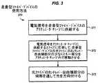
図3は、本発明の実施形態による、走査型ファイバ・デバイスの使用方法370のブロック・フロー図である。ブロック371において、例えば、前述の1つ又はそれ以上の導電性経路を介して、電気信号を走査型ファイバ・デバイスのアクチュエータ・チューブに供給することができる。 FIG. 3 is a block flow diagram of a
電気信号をアクチュエータ・チューブに供給するのに応答して、アクチュエータ・チューブは、カンチレバー自由端部分を作動又は移動させることができる。ブロック372において、光ファイバのカンチレバー自由端部分の少なくとも一部分は、アクチュエータ・チューブ内で振動又は別様に移動することができる。例として、図2において断続線を用いて、光ファイバのカンチレバー自由端部分がアクチュエータ・チューブ内で移動できることを示し、その移動の結果として光ファイバのカンチレバー自由端部分の可能な交互の位置を示す。 In response to supplying an electrical signal to the actuator tube, the actuator tube can actuate or move the cantilever free end portion. At
本発明の実施形態において、光ファイバのカンチレバー自由端部分は、アクチュエータ・チューブによって2次元の走査パターンで移動させることができる。適切な走査パターンは、それらに限定されないが、楕円、円、螺旋、プロペラ・パターン、及びこれらの組合せのような放射状走査パターン、並びに、ラスタ走査パターン、リサジュー走査パターン、及びこれらの組合せのような非放射状パターンを含む。図4は、本発明の実施形態による、適切な螺旋走査パターンの一例を示す。螺旋走査パターンは、走査中に光ファイバの自由遠位先端部が辿る種々異なる位置、及び/又は走査型ビーム・デバイスの場合には、走査中に自由遠位先端部の端部から放射されるビーム又は照射スポットの表面上の位置を表すことができる。1つの点を用いて瞬間的な時間の位置を示す。 In embodiments of the invention, the cantilever free end portion of the optical fiber can be moved in a two-dimensional scanning pattern by an actuator tube. Suitable scan patterns include, but are not limited to, radial scan patterns such as ellipses, circles, spirals, propeller patterns, and combinations thereof, and raster scan patterns, Lissajous scan patterns, and combinations thereof. Includes non-radial patterns. FIG. 4 shows an example of a suitable helical scan pattern according to an embodiment of the present invention. The helical scan pattern is emitted from different positions followed by the free distal tip of the optical fiber during scanning and / or in the case of a scanning beam device from the end of the free distal tip during scanning. The position on the surface of the beam or illumination spot can be represented. One point is used to indicate the instantaneous time position.
光ファイバは種々の周波数で振動又は移動させることができるが、本発明の実施形態においては、光ファイバは、その機械的又は振動的共振周波数(又はその高調波)のうちの1つの近くで、或いはその機械的又は振動的共振周波数(又はその高調波)のうちの1つのQ値内で振動又は移動させることができる。図5は、本発明の実施形態による、光ファイバをその共振周波数のQ値内で振動又は移動させて、機械的な増幅を得ることを示す。周波数がx軸にプロットされ、これに対する変位がy軸にプロットされる。説明図において、変位は、光ファイバの最大変位が共振周波数で起る相対的にガウス型の周波数依存性を有するように示される。実際には、このようなガウス型依存性からの著しいずれがあり得るが、変位は、依然として典型的には共振周波数でピークに達する。曲線の幅に対する曲線の高さの比が、所謂共振系の「Q値」である。共振周波数のQ値内で光ファイバを振動又は移動させることは、走査を実行するのに必要なエネルギーを減少させ、及び/又は同じ駆動信号に対してより大きな変位を可能にするのに役立ち得る。 Although an optical fiber can be vibrated or moved at various frequencies, in embodiments of the present invention, an optical fiber can be near one of its mechanical or vibrational resonant frequencies (or its harmonics) Alternatively, it can be oscillated or moved within one Q value of its mechanical or vibrational resonance frequency (or its harmonic). FIG. 5 shows that an optical fiber is vibrated or moved within the Q value of its resonant frequency to obtain mechanical amplification according to an embodiment of the present invention. The frequency is plotted on the x-axis and the displacement relative to this is plotted on the y-axis. In the illustration, the displacement is shown to have a relatively Gaussian frequency dependence where the maximum displacement of the optical fiber occurs at the resonant frequency. In practice, there can be a significant deviation from such a Gaussian dependence, but the displacement still typically peaks at the resonant frequency. The ratio of the height of the curve to the width of the curve is the so-called “Q value” of the resonance system. Vibrating or moving the optical fiber within the Q value of the resonant frequency can help reduce the energy required to perform the scan and / or allow greater displacement for the same drive signal. .
光ファイバの移動を用いて画像を構成することができる。ブロック373において、走査中に光ファイバのカンチレバー自由端部分を振動又は移動させながら、光を、光ファイバのカンチレバー自由端部分の自由遠位端を通して方向付けることができる。画像の構成は、ある表面上に画像を表示すること及び/又は表面の画像を取得することを含むことができる。表面上に画像を表示又は形成する際には、光ファイバの端部から放射された光を、走査中にピクセル位置に応じて調整し、レンズ系を通して所望の画像を表面上に形成することができる。表面の画像を取得する際には、走査型ファイバ・デバイスは、レンズ系を通して走査内の表面にわたって照射スポットを走査することができる。後方散乱光は、例えば、1つ又はそれ以上の光ファイバ又はフォト検出器によって時系列で捕捉することができる。 Images can be constructed using optical fiber movement. At
再度、図2を参照すると、断続線で示すように、第1の共振モードで振動するとき、自由遠位端又は先端部は、最大の変位を有することができる。所望の走査ズーム又は大きさを達成するために、自由遠位端又は先端部のある特定量の変位が必要となる可能性がある。この所望の走査ズーム又は大きさを達成するために、カンチレバー自由端部分は、ある特定の最小の長さを有する必要があり得る。図1の構成を用いる場合には、カンチレバー自由端部分とアクチュエータ・チューブの組み立てられた状態での長さは、一般にそれら個々の長さの各々の和よりも大きい。しかしながら、図2の構成を用いる場合には、所望の走査ズーム又は大きさを達成するのに必要な光ファイバの最小の長さの少なくとも一部分又は全てをアクチュエータ・チューブ内で振動させることができ、アクチュエータ・チューブと長さを同延にすることができる。有利なことに、この後者の構成は、同じレベルの走査ズーム又は大きさ(例えば、自由遠位端又は先端部の同じ変位量)を、カンチレバー自由端部分とアクチュエータ・チューブの組み立てられた状態での著しく短い長さ及び/又は著しく短いハウジングによって達成することを可能にすることができる。さらに、光ファイバのカンチレバー自由端部分は、代替的に、第2の共振モードで振動させることができ、このモードは、一般に、所望の走査ズーム又は大きさを得るのに必要な最小の長さを大きくして、図2の構成をさらにより有利なものにする。 Referring again to FIG. 2, the free distal end or tip can have the greatest displacement when oscillating in the first resonance mode, as shown by the interrupted line. A certain amount of displacement of the free distal end or tip may be required to achieve the desired scanning zoom or size. In order to achieve this desired scanning zoom or size, the cantilever free end portion may need to have a certain minimum length. When the configuration of FIG. 1 is used, the assembled length of the cantilever free end and the actuator tube is generally greater than the sum of their respective lengths. However, when using the configuration of FIG. 2, at least a portion or all of the minimum length of optical fiber required to achieve the desired scanning zoom or size can be vibrated in the actuator tube; The length can be the same as that of the actuator tube. Advantageously, this latter configuration provides the same level of scanning zoom or magnitude (eg, the same amount of displacement at the free distal end or tip), with the cantilever free end portion and the actuator tube assembled. Can be achieved with a significantly shorter length and / or a significantly shorter housing. Furthermore, the cantilever free end portion of the optical fiber can alternatively be oscillated in a second resonant mode, which is generally the minimum length necessary to obtain the desired scanning zoom or size. To make the configuration of FIG. 2 even more advantageous.
ここで、光ファイバのカンチレバー自由端部分の実質的に全てがアクチュエータ・チューブ内に配置され、第1の共振モードで振動する場合(自由遠位端又は先端部が最大の変位を有する場合)には、アクチュエータ・チューブの内径は、所望の走査ズーム又は大きさに対して、自由遠位端又は先端部の全変位又は振れを収容するのに十分大きくする必要があり得る。しかしながら、本発明の実施形態においては、光ファイバのカンチレバー自由端部分の遠位端部分は、自由遠位端部又は先端部を含むが、アクチュエータ・チューブの遠位端を越えて延びることができる。 Here, when substantially all of the cantilever free end portion of the optical fiber is disposed within the actuator tube and vibrates in the first resonance mode (when the free distal end or tip has the maximum displacement). The inner diameter of the actuator tube may need to be large enough to accommodate the total displacement or deflection of the free distal end or tip for the desired scanning zoom or size. However, in embodiments of the present invention, the distal end portion of the optical fiber cantilever free end portion includes a free distal end or tip, but can extend beyond the distal end of the actuator tube. .
図6は、別の例示的な走査型ファイバ・デバイス620の側断面図であり、本発明の実施形態による、光ファイバ635のカンチレバー自由端部分630の自由遠位端部分676がアクチュエータ・チューブ625の端部を越えて延びている。この走査型ファイバ・デバイスは、ハウジング650、アクチュエータ・チューブ625、光ファイバ635のカンチレバー自由端部分630、リング型プラグ又は他の物理的結合デバイス若しくはコンポーネント660、取付けカラー又は他の物理的結合デバイス若しくはコンポーネント665、1つ又はそれ以上の導電性経路667、及びハウジングの透明部分668を含む。光ファイバのカンチレバー自由端部分は、取付け端640、及び自由遠位端又は先端部645を有する。特に指定のない限り、これらのコンポーネントは、随意的に、図2の走査型ファイバ・デバイス220の対応するコンポーネントの特徴の幾つか又は全てを有することができる。特定の概念を不明瞭にするのを避けるために、以下の説明は、主にこの例示的な走査型ファイバ・デバイス620の種々の及び/又は付加的な構造体及び特徴に重点を置く。 FIG. 6 is a cross-sectional side view of another exemplary
図示したように、本発明の実施形態において、光ファイバのカンチレバー自由端部分の長さの近位部分675は、アクチュエータ・チューブ内に配置することができ、アクチュエータ・チューブ内で振動又は移動することができる。図示したデバイスにおいては、カンチレバー自由端部分の半分より僅かに大きい部分がアクチュエータ・チューブ内に配置されるが、このことは必須ではない。代替的な実施形態においては、カンチレバー自由端部分のより大きな又はより小さな部分をアクチュエータ・チューブ内に配置することができる。例えば、本発明の種々の実施形態において、カンチレバー自由端部分の長さの、少なくとも10分の1、少なくとも4分の1、又は少なくとも2分の1であるが、実質的に全てではない部分をアクチュエータ・チューブ内に配置することができる。前述のように、カンチレバー自由端部分の長さの少なくとも一部分をアクチュエータ・チューブ内に配置することは、組み立てられた状態でアクチュエータ・チューブにカンチレバー自由端部分を加えた全長を減らすのに役立つことになる。 As shown, in an embodiment of the present invention, the
さらに図示したように、本発明の実施形態において、光ファイバのカンチレバー自由端部分の遠位端部分676は、アクチュエータ・チューブ625の遠位端を越えて延びることができる。同様に、自由遠位端又は先端部645は、アクチュエータ・チューブを超えて延びることができる。 As further illustrated, in an embodiment of the present invention, the
アクチュエータ・チューブを超えて遠位端部分を延ばすと、随意的かつ可能的に、アクチュエータ・チューブの直径を減らすことが可能になり得る。断続線を用いて、光ファイバのカンチレバー自由端部分の移動の結果としての可能な交互位置を示す。図示したように、近位部分は、アクチュエータ・チューブ内で振動又は移動することができ、一方、自由遠位端又は先端部を含む遠位端部分は、アクチュエータ・チューブの外で振動又は移動することができる。第1の共振モードにおいて、自由遠位端又は先端部の移動は、アクチュエータ・チューブの内径又は他の断面寸法(ID)より大きい範囲又は長さ(L)で移動又は振らせることができることに留意されたい。アクチュエータ・チューブの内径又は断面寸法は、自由遠位端又は先端部の全振れ又は変位を収容するのに十分に大きくする必要はない。このように、遠位端部分がアクチュエータ・チューブを超えて延びることを可能にすると、随意的かつ可能的に、より小さい直径又は断面のアクチュエータ・チューブを用いることが可能になり、このことは、デバイス寸法を減少させ、及び/又は所与の走査ズーム又は大きさに対してより低い電圧を用いてファイバを走査することを可能にするのに役立ち得る。 Extending the distal end portion beyond the actuator tube may optionally and possibly reduce the diameter of the actuator tube. Intermittent lines are used to show possible alternate positions as a result of movement of the free end of the cantilever of the optical fiber. As shown, the proximal portion can oscillate or move within the actuator tube, while the distal end portion including the free distal end or tip oscillates or moves outside the actuator tube. be able to. Note that in the first resonant mode, the movement of the free distal end or tip can be moved or swung in a range or length (L) greater than the inner diameter or other cross-sectional dimension (ID) of the actuator tube. I want to be. The inner diameter or cross-sectional dimension of the actuator tube need not be large enough to accommodate the full deflection or displacement of the free distal end or tip. Thus, allowing the distal end portion to extend beyond the actuator tube can optionally and possibly use a smaller diameter or cross-section actuator tube, It may help to reduce device dimensions and / or allow scanning of the fiber using a lower voltage for a given scan zoom or size.
より小さい直径のアクチュエータ・チューブは、より大きい直径のアクチュエータ・チューブよりも、同じ駆動電圧に対してより大きな変位を生じることが容易であり、このことは、アクチュエータ・チューブを駆動するのに用いられる電子回路を単純化することを容易にし得る。しかしながら、光ファイバのカンチレバー自由端部分の少なくとも一部分を円筒型アクチュエータ・チューブ内で振動又は移動させる場合には、円筒型アクチュエータ・チューブの直径又は他の断面寸法は、光ファイバのカンチレバー自由端部分の一部分の振動又は運動を内部に収容するのに十分大きくする必要があり得る。このことは、円筒型アクチュエータ・チューブの直径又は他の断面寸法を望ましい大きさよりも大きくする可能性がある。本発明の1つ又はそれ以上の実施形態において、随意的に、テーパ型アクチュエータ・チューブを用いて、取付け近位端においてより小さい直径又は断面寸法を与え、同じ駆動電圧に対してより大きなファイバ変位をもたらし、そして、自由遠位端においてより大きい直径又は断面寸法を与え、ファイバ移動のためのより広いスペースをもたらすことができる。 A smaller diameter actuator tube is easier to produce a larger displacement for the same drive voltage than a larger diameter actuator tube, which is used to drive the actuator tube It can facilitate simplifying the electronic circuit. However, if at least a portion of the optical fiber cantilever free end portion is vibrated or moved within the cylindrical actuator tube, the diameter or other cross-sectional dimensions of the cylindrical actuator tube may be the same as the cantilever free end portion of the optical fiber. It may need to be large enough to accommodate a portion of the vibration or movement inside. This can cause the diameter or other cross-sectional dimensions of the cylindrical actuator tube to be larger than desired. In one or more embodiments of the present invention, optionally, a tapered actuator tube is used to provide a smaller diameter or cross-sectional dimension at the mounting proximal end, resulting in greater fiber displacement for the same drive voltage. And can provide a larger diameter or cross-sectional dimension at the free distal end, resulting in a wider space for fiber movement.
図7は、本発明の実施形態による、テーパ型アクチュエータ・チューブ725を有する、例示的な走査型ファイバ・デバイス720の側断面図である。この走査型ファイバ・デバイスは、ハウジング750、テーパ型アクチュエータ・チューブ725、光ファイバ735のカンチレバー自由端部分730、接着剤のビード又は他の物理的結合デバイス若しくはコンポーネント760、取付けカラー又は他の物理的結合デバイス若しくはコンポーネント765、1つ又はそれ以上の導電性経路767、及びハウジングの透明部分768を含む。光ファイバのカンチレバー自由端部分は、取付け端740及び自由遠位端又は先端部745を有する。特に指定のない限り、これらのコンポーネントは、随意的に、図2に示した走査型ファイバ・デバイス220の、対応して命名されたコンポーネントの特徴の幾つか又は全てを有することができる。特定の概念を不明瞭にすることを避けるために、以下の説明は、主に例示的な走査型ファイバ・デバイス720の種々の及び/又は付加的な構造及び特徴に重点を置く。 FIG. 7 is a cross-sectional side view of an exemplary
テーパ型アクチュエータ・チューブはテーパ加工され、直径又は断面が一端部に向かって次第に小さくなる。具体的には、図に見られるように、テーパ型アクチュエータ・チューブは、直径又は断面が右の遠位側から左の近位側に向って次第に小さくなる。例として、テーパ型圧電チューブは、成形又は微細機械加工によって作ることができる。 The tapered actuator tube is tapered and the diameter or cross section gradually decreases toward one end. Specifically, as seen in the figure, the tapered actuator tube gradually decreases in diameter or cross-section from the right distal side to the left proximal side. As an example, a tapered piezoelectric tube can be made by molding or micromachining.
テーパ型アクチュエータ・チューブは、第1の内径又は他の断面寸法(ID1)を遠位端で有し、第2の内径又は他の内側断面寸法(ID2)を近位端で有する。第1及び第2の内径は、実質的に異なるものとすることができる。本明細書において用いられる第1及び第2の直径は、それらが10%より大きく異なる場合に実質的に異なるものとすることができる。具体的には、光ファイバのカンチレバー自由端部分の移動がより大きな遠位端における第1の内径は、光ファイバのカンチレバー自由端部分が取り付けられる近位端における第2の内径よりも大きくすることができる。 The tapered actuator tube has a first inner diameter or other cross-sectional dimension (ID1) at the distal end and a second inner diameter or other inner cross-sectional dimension (ID2) at the proximal end. The first and second inner diameters can be substantially different. The first and second diameters used herein can be substantially different if they differ by more than 10%. Specifically, the first inner diameter at the distal end where the movement of the cantilever free end portion of the optical fiber is larger should be larger than the second inner diameter at the proximal end where the cantilever free end portion of the optical fiber is attached. Can do.
第1及び第2の内径は、様々な量だけ異なるものとすることができる。典型的には、遠位端における第1の内径は、近位端における第2の内径より約10%乃至1000%大きくすることができる。一般に、第1の内径は、第2の内径より約50%乃至500%大きくすることができる。特定の実施形態において、第1の内径は、第2の内径よりより約50%乃至300%大きくすることができる。1つの特定の実施形態において、第1の内径は、第2の内径の約2倍の大きさにすることができる。 The first and second inner diameters can differ by various amounts. Typically, the first inner diameter at the distal end can be about 10% to 1000% greater than the second inner diameter at the proximal end. In general, the first inner diameter can be about 50% to 500% larger than the second inner diameter. In certain embodiments, the first inner diameter can be about 50% to 300% greater than the second inner diameter. In one particular embodiment, the first inner diameter can be about twice as large as the second inner diameter.
一般に、テーパ型アクチュエータ・チューブは、切頭中空円錐形状を有することができるが、このことは必須ではない。切頭楕円ベースの中空円錐又は切頭多角形ベースのピラミッドも、場合によっては適切である。 In general, a tapered actuator tube can have a truncated hollow cone shape, but this is not essential. A truncated elliptical-based hollow cone or truncated polygon-based pyramid is also suitable in some cases.
テーパ型アクチュエータ・チューブの別の可能性のある利点は、光ファイバのカンチレバー自由端部分の物理的結合又は取付けにあり得る。テーパ型アクチュエータ・チューブの近位端における相対的に小さい内径又は他の断面寸法は、接着剤によるアクチュエータ・チューブと取付け端の物理的結合を容易にするのに役立ち得る。相対的に小さい内径又は断面はまた、アクチュエータ・チューブの開口部内での光ファイバの正確なセンタリングを容易にするのに役立ち得る。 Another possible advantage of the tapered actuator tube may be in the physical coupling or attachment of the free end portion of the optical fiber cantilever. A relatively small inner diameter or other cross-sectional dimension at the proximal end of the tapered actuator tube can help facilitate the physical coupling of the actuator tube and the mounting end by an adhesive. A relatively small inner diameter or cross section can also help to facilitate precise centering of the optical fiber within the opening of the actuator tube.
走査型ファイバ・デバイスの図示した例においては、光ファイバのカンチレバー自由端部分の実質的に全て(その自由遠位端又は先端部を含む)が、テーパ型アクチュエータ・チューブ内に配置されるが、このことは必須ではない。しかしながら、代替的な実施形態においては、光ファイバのカンチレバー自由端部分の遠位端部分は、前述のように、テーパ型アクチュエータ・チューブの遠位端を越えて延びることができることを認識されたい。 In the illustrated example of a scanning fiber device, substantially all of the cantilever free end portion of the optical fiber (including its free distal end or tip) is disposed within the tapered actuator tube, This is not essential. However, it will be appreciated that in alternative embodiments, the distal end portion of the optical fiber cantilever free end portion may extend beyond the distal end of the tapered actuator tube, as described above.
本説明及び特許請求の範囲において、「結合された」及び「接続された」という用語並びにそれらの派生語が用いられる。特に指定のない限り、これらの用語は、互いに同義語として意図されたものではない。むしろ、「接続された」とは、2つ又はそれ以上の要素が互いに直接物理的又は電気的に接触することを示すために用いることができる。「結合された」とは、2つ又はそれ以上の要素が直接物理的又は電気的に接触することを意味することができる。しかしながら、「結合された」はまた、2つ又はそれ以上の要素が互いに直接に接触しないが、それでもなお互いに物理的、電気的又は光学的に協働する又は相互作用することを意味することもできる。例えば、光ファイバのカンチレバー自由端部分は、リング型プラグ及び/又は接着剤、或いは他の介在するデバイス及び/又はコンポーネントによってアクチュエータ・チューブと結合することができる。 In this description and in the claims, the terms “coupled” and “connected” and their derivatives are used. Unless otherwise specified, these terms are not intended as synonyms for each other. Rather, “connected” can be used to indicate that two or more elements are in direct physical or electrical contact with each other. “Coupled” may mean that two or more elements are in direct physical or electrical contact. However, “coupled” also means that two or more elements do not directly contact each other, but still physically or electrically cooperate or interact with each other. You can also. For example, the cantilever free end portion of the optical fiber can be coupled to the actuator tube by a ring-type plug and / or adhesive, or other intervening device and / or component.
本説明及び特許請求の範囲において、特に指定のない限り、「走査型ファイバ・デバイス」における「走査型」という用語等は、デバイスが使用中であるか、又は現在走査プロセス中であることを、特に指定のない限り意味するものではない。むしろ、この「走査型」という用語は、単にデバイスが走査する機能を有することを意味する。 In this description and in the claims, unless otherwise specified, the term “scanning fiber” in “scanning fiber device” means that the device is in use or is currently in the scanning process, It does not mean unless otherwise specified. Rather, the term “scanning” simply means that the device has the ability to scan.
上の説明においては、説明の目的で、本発明の実施形態の完全な理解を与えるために多数の特定の細部を示した。説明された特定の実施形態は、本発明を限定するために与えられるものではなく、それを例示するために与えられるものである。これらの特定の細部の幾つかを用いずに実施形態を実施することができる。さらに、例えば、実施形態のコンポーネントの、サイズ、形状、構成、形態、機能、材料及び動作方法、並びに組立て及び使用方法に対するような修正を、本明細書で開示された実施形態に加えることができる。図面に示され、本明細書において説明されたのと等価な全ての関係が、本発明の実施形態の中に含まれる。本発明の範囲は、以上に与えられた特定の実施例によってではなく、以下の特許請求の範囲によって定められる。さらに、適切と考えられる場合には、参照符号の末尾部分を図面の間で繰返して、随意に同じ特性を有することができる対応する又は類似の要素を示した。 In the above description, for the purposes of explanation, numerous specific details are set forth in order to provide a thorough understanding of the embodiments of the invention. The particular embodiments described are not given to limit the invention but to illustrate it. Embodiments can be practiced without some of these specific details. Further, modifications such as, for example, the size, shape, configuration, form, function, material and operation method, and assembly and use method of the components of the embodiment can be made to the embodiments disclosed herein. . All relationships equivalent to those shown in the drawings and described herein are included in the embodiments of the present invention. The scope of the present invention is defined by the following claims rather than by the specific examples given above. In addition, where considered appropriate, the tail portions of the reference signs have been repeated among the drawings to indicate corresponding or similar elements that may optionally have the same characteristics.
また本明細書全体にわたる、例えば、「1つの実施形態」、「一実施形態」又は「1つ又はそれ以上の実施形態」に対する言及は、特定の特徴を本発明の実施に含めることができることを意味することを認識されたい。同様に、本開示を簡素化し、本発明の種々の態様の理解を助ける目的で、本説明において、場合により種々の特徴が、単一の実施形態、図面、又はその説明に集められていることを認識されたい。しかしながら、この開示の方法は、本発明が各々の請求項において明白に記述されるよりも多くの特徴を必要とするという意図を反映するものと解釈すべきではない。むしろ、以下の特許請求の範囲が記述するように、本発明の態様は、単一の開示された実施形態の特徴の全てよりは少ない中にあり得る。従って、「発明を実施するための形態」に続く特許請求の範囲は、本明細書では「発明を実施するための形態」に明白に組み入れられ、各々の請求項は、本発明の別々の実施形態としてそれ自体で成立するものである。 Also, throughout this specification, for example, reference to “an embodiment,” “one embodiment,” or “one or more embodiments” means that certain features can be included in the practice of the invention. Recognize what it means. Similarly, for the purpose of simplifying the present disclosure and assisting in understanding various aspects of the present invention, various features are sometimes collected in the description into a single embodiment, drawing, or description thereof, in the description. I want to be recognized. This method of disclosure, however, should not be interpreted as reflecting an intention that the invention requires more features than are expressly recited in each claim. Rather, as the following claims describe, aspects of the invention may be in less than all of the features of a single disclosed embodiment. Thus, the claims following the “DETAILED DESCRIPTION OF THE INVENTION” are expressly incorporated herein by reference to “Modes for Carrying Out the Invention”, and each claim is a separate implementation of the present invention. It is established by itself as a form.
100:走査型ファイバ・デバイス
102:ハウジング
104:圧電チューブ
106:取付けカラー
108:光ファイバ
110:カンチレバー自由端部分
112:電極
114:ワイヤ
220、620、720:走査型ファイバ・デバイス
225、625、725:アクチュエータ・チューブ
230、630、730:カンチレバー自由端部分
235、635、735:光ファイバ
240、640、740:取付け端
245、645、745:自由遠位端又は先端部
250、650、750:ハウジング
255:通常の部分
260:介在コンポーネント
267、667、767:導電性経路
265、665、765:取付けカラー
268、668、768:ハウジングの透明部分
370:方法
660:リング型プラグ
675:近位部分
676:自由遠位端部分
760:接着剤のビード100: scanning fiber device 102: housing 104: piezoelectric tube 106: mounting collar 108: optical fiber 110: cantilever free end portion 112: electrode 114:
Claims (8)
Translated fromJapanese該ハウジング内に配置されるアクチュエータ・チューブと、
前記アクチュエータ・チューブに結合された取付け端と該アクチュエータ・チューブによって動かされる自由端とを有する、光ファイバのカンチレバー自由端部分と、
を備え、
前記光ファイバの前記カンチレバー自由端部分の長さの少なくとも一部分が、前記アクチュエータ・チューブ内に配置され、
前記アクチュエータ・チューブは前記光ファイバとともに延びており、該光ファイバを2次元で移動できるようにしている、
ことを特徴とする走査型ファイバ・デバイス。A housing;
An actuator tube disposed within the housing;
An optical fiber cantilever free end portion having a mounting end coupled to the actuator tube and a free end moved by the actuator tube;
With
At least a portion of the length of the cantilever free end portion of the optical fiber is disposed within the actuator tube;
The actuator tube extends with the optical fiber, allowing the optical fiber to move in two dimensions;
A scanning fiber device characterized by the above.
Applications Claiming Priority (3)
| Application Number | Priority Date | Filing Date | Title |
|---|---|---|---|
| US11/784,488US7583872B2 (en) | 2007-04-05 | 2007-04-05 | Compact scanning fiber device |
| US11/784,488 | 2007-04-05 | ||
| PCT/US2007/015574WO2008123859A1 (en) | 2007-04-05 | 2007-07-06 | Compact scanning fiber device |
Publications (2)
| Publication Number | Publication Date |
|---|---|
| JP2010523198A JP2010523198A (en) | 2010-07-15 |
| JP5535061B2true JP5535061B2 (en) | 2014-07-02 |
Family
ID=39015848
Family Applications (1)
| Application Number | Title | Priority Date | Filing Date |
|---|---|---|---|
| JP2010502065AActiveJP5535061B2 (en) | 2007-04-05 | 2007-07-06 | Compact scanning fiber device |
Country Status (4)
| Country | Link |
|---|---|
| US (1) | US7583872B2 (en) |
| EP (1) | EP2134236B1 (en) |
| JP (1) | JP5535061B2 (en) |
| WO (1) | WO2008123859A1 (en) |
Families Citing this family (105)
| Publication number | Priority date | Publication date | Assignee | Title |
|---|---|---|---|---|
| US7102758B2 (en) | 2003-05-06 | 2006-09-05 | Duke University | Fourier domain low-coherence interferometry for light scattering spectroscopy apparatus and method |
| US8537366B2 (en) | 2005-10-11 | 2013-09-17 | Duke University | Systems and methods for endoscopic angle-resolved low coherence interferometry |
| CA2967964A1 (en)* | 2005-10-11 | 2007-04-19 | Duke University | Systems and method for endoscopic angle-resolved low coherence interferometry |
| CN103815860A (en)* | 2006-07-21 | 2014-05-28 | 昂科斯科公司 | Protective probe tip, particularly for use on fiber-optic probe used in endoscopic application |
| US9125552B2 (en)* | 2007-07-31 | 2015-09-08 | Ethicon Endo-Surgery, Inc. | Optical scanning module and means for attaching the module to medical instruments for introducing the module into the anatomy |
| US20090073456A1 (en)* | 2007-09-13 | 2009-03-19 | Duke University | Apparatuses, systems, and methods for low-coherence interferometry (lci) |
| AU2009204187B2 (en)* | 2008-01-08 | 2015-02-05 | Oncoscope, Inc. | Systems and methods for tissue examination, diagnostic, treatment, and/or monitoring |
| US8696695B2 (en) | 2009-04-28 | 2014-04-15 | Avinger, Inc. | Guidewire positioning catheter |
| US9788790B2 (en) | 2009-05-28 | 2017-10-17 | Avinger, Inc. | Optical coherence tomography for biological imaging |
| US9125562B2 (en) | 2009-07-01 | 2015-09-08 | Avinger, Inc. | Catheter-based off-axis optical coherence tomography imaging system |
| US8062316B2 (en) | 2008-04-23 | 2011-11-22 | Avinger, Inc. | Catheter system and method for boring through blocked vascular passages |
| JP2010097083A (en)* | 2008-10-17 | 2010-04-30 | Hoya Corp | Optical fiber scanner and endoscope device |
| JP5210823B2 (en)* | 2008-11-19 | 2013-06-12 | Hoya株式会社 | Optical scanning endoscope, optical scanning endoscope processor, and optical scanning endoscope apparatus |
| JP2010253155A (en)* | 2009-04-28 | 2010-11-11 | Fujifilm Corp | Endoscope system, endoscope, and endoscope driving method |
| JP2010253156A (en)* | 2009-04-28 | 2010-11-11 | Fujifilm Corp | Endoscope system, endoscope, and endoscope driving method |
| JP2010284369A (en)* | 2009-06-12 | 2010-12-24 | Fujifilm Corp | Endoscope system, endoscope, and endoscope driving method |
| WO2011003006A2 (en) | 2009-07-01 | 2011-01-06 | Avinger, Inc. | Atherectomy catheter with laterally-displaceable tip |
| WO2011072068A2 (en) | 2009-12-08 | 2011-06-16 | Avinger, Inc. | Devices and methods for predicting and preventing restenosis |
| WO2011091369A1 (en) | 2010-01-22 | 2011-07-28 | Duke University | Multiple window processing schemes for spectroscopic optical coherence tomography (oct) and fourier domain low coherence interferometry |
| US9823127B2 (en) | 2010-01-22 | 2017-11-21 | Duke University | Systems and methods for deep spectroscopic imaging of biological samples with use of an interferometer and spectrometer |
| EP2380482A1 (en)* | 2010-04-21 | 2011-10-26 | Koninklijke Philips Electronics N.V. | Extending image information |
| US9345510B2 (en) | 2010-07-01 | 2016-05-24 | Avinger, Inc. | Atherectomy catheters with longitudinally displaceable drive shafts |
| WO2014039096A1 (en) | 2012-09-06 | 2014-03-13 | Avinger, Inc. | Re-entry stylet for catheter |
| US11382653B2 (en) | 2010-07-01 | 2022-07-12 | Avinger, Inc. | Atherectomy catheter |
| US10548478B2 (en) | 2010-07-01 | 2020-02-04 | Avinger, Inc. | Balloon atherectomy catheters with imaging |
| US8503837B2 (en)* | 2011-03-01 | 2013-08-06 | The United States Of America As Represented By The Secretary Of The Army | Compact fiber optic positioner with wide frequency bandwidth |
| US8900126B2 (en) | 2011-03-23 | 2014-12-02 | United Sciences, Llc | Optical scanning device |
| EP2691038B1 (en) | 2011-03-28 | 2016-07-20 | Avinger, Inc. | Occlusion-crossing devices, imaging, and atherectomy devices |
| US9949754B2 (en) | 2011-03-28 | 2018-04-24 | Avinger, Inc. | Occlusion-crossing devices |
| EP2708021B1 (en) | 2011-05-12 | 2019-07-10 | DePuy Synthes Products, Inc. | Image sensor with tolerance optimizing interconnects |
| US9572571B2 (en) | 2011-09-09 | 2017-02-21 | Endogastric Solutions, Inc. | Methods and devices for manipulating and fastening tissue |
| US20130066338A1 (en) | 2011-09-09 | 2013-03-14 | Richard Romley | Methods and devices for manipulating and fastening tissue |
| EP3653151A1 (en) | 2011-10-17 | 2020-05-20 | Avinger, Inc. | Atherectomy catheters and non-contact actuation mechanism for catheters |
| JPWO2013069382A1 (en)* | 2011-11-09 | 2015-04-02 | オリンパス株式会社 | Endoscope |
| US9345406B2 (en) | 2011-11-11 | 2016-05-24 | Avinger, Inc. | Occlusion-crossing devices, atherectomy devices, and imaging |
| JP2013158445A (en)* | 2012-02-03 | 2013-08-19 | Hoya Corp | Scanning probe, scanning observation system, integrated endoscope, and integrated endoscopic system |
| EP3611556B1 (en)* | 2012-02-16 | 2020-11-18 | University Of Washington Through Its Center For Commercialization | Extended depth of focus for high-resolution image scanning |
| US8900125B2 (en) | 2012-03-12 | 2014-12-02 | United Sciences, Llc | Otoscanning with 3D modeling |
| US9557156B2 (en) | 2012-05-14 | 2017-01-31 | Avinger, Inc. | Optical coherence tomography with graded index fiber for biological imaging |
| WO2013172970A1 (en) | 2012-05-14 | 2013-11-21 | Avinger, Inc. | Atherectomy catheters with imaging |
| EP2849660B1 (en) | 2012-05-14 | 2021-08-25 | Avinger, Inc. | Atherectomy catheter drive assemblies |
| EP2730212A4 (en)* | 2012-06-28 | 2015-04-15 | Olympus Medical Systems Corp | SCANNING ENDOSCOPE AND METHOD FOR MANUFACTURING SCANNING ENDOSCOPE |
| US9462234B2 (en) | 2012-07-26 | 2016-10-04 | DePuy Synthes Products, Inc. | Camera system with minimal area monolithic CMOS image sensor |
| MX389501B (en) | 2012-07-26 | 2025-03-20 | Depuy Synthes Products Inc | CONTINUOUS VIDEO IN A LIGHT-POOR ENVIRONMENT |
| MX346174B (en) | 2012-07-26 | 2017-03-10 | Depuy Synthes Products Inc | YCBCR PULSED LIGHTING SCHEME IN A DEFICIENT LIGHT ENVIRONMENT. |
| US11284916B2 (en) | 2012-09-06 | 2022-03-29 | Avinger, Inc. | Atherectomy catheters and occlusion crossing devices |
| US9498247B2 (en) | 2014-02-06 | 2016-11-22 | Avinger, Inc. | Atherectomy catheters and occlusion crossing devices |
| CN103889309A (en)* | 2012-09-13 | 2014-06-25 | 奥林巴斯医疗株式会社 | Endoscopic system |
| JP6057743B2 (en)* | 2013-01-29 | 2017-01-11 | オリンパス株式会社 | Optical scanning device |
| SG11201505461PA (en) | 2013-02-04 | 2015-08-28 | Helen Of Troy Ltd | Otoscope |
| MX363569B (en) | 2013-02-04 | 2019-03-27 | Helen Of Troy Ltd | Ear inspection device and method of determining a condition of a subject's ear. |
| EP2787333B1 (en)* | 2013-04-05 | 2018-02-14 | Helen of Troy Limited | Ear inspection device and method of determining a condition of a subject's ear |
| HK1219856A1 (en) | 2013-02-04 | 2017-04-21 | Helen Of Troy Limited | Otoscope |
| EP2950696B1 (en) | 2013-02-04 | 2020-04-29 | Helen of Troy Limited | Method for identifying objects in a subject's ear |
| CN105228514B (en) | 2013-03-15 | 2019-01-22 | 阿维格公司 | Optical Pressure Sensor Assembly |
| CA2906975A1 (en) | 2013-03-15 | 2014-09-18 | Olive Medical Corporation | Minimize image sensor i/o and conductor counts in endoscope applications |
| WO2014143064A1 (en) | 2013-03-15 | 2014-09-18 | Avinger, Inc. | Chronic total occlusion crossing devices with imaging |
| WO2014144947A1 (en) | 2013-03-15 | 2014-09-18 | Olive Medical Corporation | Super resolution and color motion artifact correction in a pulsed color imaging system |
| CA2906821A1 (en) | 2013-03-15 | 2014-09-18 | Olive Medical Corporation | Scope sensing in a light controlled environment |
| BR112015022987A2 (en) | 2013-03-15 | 2017-07-18 | Olive Medical Corp | integrated prism trocar visualization for use with angled endoscope |
| US11096717B2 (en) | 2013-03-15 | 2021-08-24 | Avinger, Inc. | Tissue collection device for catheter |
| EP2967285B1 (en) | 2013-03-15 | 2023-08-16 | DePuy Synthes Products, Inc. | Image sensor synchronization without input clock and data transmission clock |
| WO2014145249A1 (en) | 2013-03-15 | 2014-09-18 | Olive Medical Corporation | Controlling the integral light energy of a laser pulse |
| CN103263246A (en)* | 2013-04-26 | 2013-08-28 | 广州宝胆医疗器械科技有限公司 | Percutaneous transhepatic choledochoscope system |
| EP3019096B1 (en) | 2013-07-08 | 2023-07-05 | Avinger, Inc. | System for identification of elastic lamina to guide interventional therapy |
| JP6129050B2 (en)* | 2013-10-08 | 2017-05-17 | オリンパス株式会社 | Optical fiber scanner, illumination device and observation device |
| JP6226730B2 (en)* | 2013-12-11 | 2017-11-08 | オリンパス株式会社 | Optical scanning device and optical scanning observation device |
| US10470656B2 (en)* | 2013-12-20 | 2019-11-12 | Novartis Ag | Imaging probes and associated devices, systems, and methods utilizing electroactive polymer actuators |
| MX2016010141A (en) | 2014-02-06 | 2017-04-06 | Avinger Inc | Atherectomy catheters and occlusion crossing devices. |
| JP6345946B2 (en)* | 2014-02-26 | 2018-06-20 | オリンパス株式会社 | Optical fiber scanner, illumination device and observation device |
| WO2015143453A1 (en) | 2014-03-21 | 2015-09-24 | Olive Medical Corporation | Card edge connector for an imaging sensor |
| JP6289253B2 (en)* | 2014-05-02 | 2018-03-07 | オリンパス株式会社 | Optical fiber scanning device and optical scanning endoscope |
| WO2015182137A1 (en)* | 2014-05-27 | 2015-12-03 | オリンパス株式会社 | Optical scanning-type endoscope device |
| JP6309356B2 (en)* | 2014-06-10 | 2018-04-11 | オリンパス株式会社 | Optical fiber scanner, illumination device and observation device |
| US10357277B2 (en) | 2014-07-08 | 2019-07-23 | Avinger, Inc. | High speed chronic total occlusion crossing devices |
| WO2016075777A1 (en) | 2014-11-12 | 2016-05-19 | オリンパス株式会社 | Optical fiber scanner, illumination device, and observation apparatus |
| JP6435349B2 (en)* | 2015-02-06 | 2018-12-05 | オリンパス株式会社 | Optical fiber scanner and scanning endoscope apparatus |
| US10568520B2 (en) | 2015-07-13 | 2020-02-25 | Avinger, Inc. | Micro-molded anamorphic reflector lens for image guided therapeutic/diagnostic catheters |
| JP6927986B2 (en) | 2016-01-25 | 2021-09-01 | アビンガー・インコーポレイテッドAvinger, Inc. | OCT imaging catheter with delay compensation |
| EP3435892B1 (en) | 2016-04-01 | 2024-04-03 | Avinger, Inc. | Atherectomy catheter with serrated cutter |
| US11344327B2 (en) | 2016-06-03 | 2022-05-31 | Avinger, Inc. | Catheter device with detachable distal end |
| WO2018006041A1 (en) | 2016-06-30 | 2018-01-04 | Avinger, Inc. | Atherectomy catheter with shapeable distal tip |
| DE102016010448B4 (en) | 2016-08-30 | 2024-01-11 | Blickfeld GmbH | Fiber-based laser scanner |
| WO2018057935A1 (en)* | 2016-09-22 | 2018-03-29 | Arizona Board Of Regents On Behalf Of The University Of Arizona | Dithered fiber-bundle imager and high-resolution imaging method |
| AU2017382871A1 (en)* | 2016-12-22 | 2019-06-13 | Magic Leap, Inc. | Methods and systems for fabrication of shaped fiber elements for scanning fiber displays |
| WO2018122916A1 (en)* | 2016-12-26 | 2018-07-05 | オリンパス株式会社 | Optical fiber scanning device and endoscope |
| WO2018161260A1 (en) | 2017-03-07 | 2018-09-13 | Goertek Inc. | Laser projection device and laser projection system |
| CA3053990A1 (en)* | 2017-03-15 | 2018-09-20 | Magic Leap, Inc. | Techniques for improving a fiber scanning system |
| CN115202035A (en) | 2017-04-04 | 2022-10-18 | 奇跃公司 | Anamorphic mode actuation for increased field of view fiber scanner |
| CN110212083B (en)* | 2018-02-28 | 2024-05-28 | 成都理想境界科技有限公司 | Piezoelectric device, optical fiber scanning driver, optical fiber scanning device and projection device |
| US12167867B2 (en) | 2018-04-19 | 2024-12-17 | Avinger, Inc. | Occlusion-crossing devices |
| WO2020006008A1 (en) | 2018-06-26 | 2020-01-02 | Magic Leap, Inc. | Raster scanned projector with microelectromechanical system scanner |
| WO2020006011A1 (en)* | 2018-06-26 | 2020-01-02 | Magic Leap, Inc. | Hybrid optical fiber mems scanner |
| KR102224891B1 (en)* | 2018-11-29 | 2021-03-09 | 재단법인대구경북과학기술원 | Fiber Scanning System |
| KR102260138B1 (en) | 2019-07-05 | 2021-06-03 | 그린스펙(주) | Optical Fiber Probe |
| US12279812B2 (en)* | 2019-08-05 | 2025-04-22 | Gyrus Acmi, Inc. | Laser fiber varying lateral position and intensity |
| CN114746033B (en) | 2019-10-18 | 2025-01-10 | 阿维格公司 | Blocking crossing device |
| US12385733B2 (en) | 2020-01-30 | 2025-08-12 | Soham Inc. | Synchronizing an optical coherence tomography system |
| US11047671B1 (en) | 2020-01-30 | 2021-06-29 | Veravanti Inc. | Forward looking RGB/optical coherence tomography duplex imager |
| US11307367B2 (en)* | 2020-08-17 | 2022-04-19 | X Development Llc | Method of precision beam collimation using fiber-optic circulator and wavelength tunable source |
| CN114384690A (en)* | 2020-10-21 | 2022-04-22 | 成都理想境界科技有限公司 | Optical fiber packaging structure of an optical fiber scanner |
| CN114384693A (en)* | 2020-10-21 | 2022-04-22 | 成都理想境界科技有限公司 | Scanning actuator and optical fiber scanner |
| EP4604865A2 (en) | 2022-10-20 | 2025-08-27 | Femtovox Incorporated | Apparatus and techniques for surgical laser delivery |
| KR20240131634A (en) | 2023-02-24 | 2024-09-02 | 젠어뷰 주식회사 | Optical fiber scanner |
| KR20240131633A (en) | 2023-02-24 | 2024-09-02 | 젠어뷰 주식회사 | (method and apparatus for optical fiber scanner |
Family Cites Families (116)
| Publication number | Priority date | Publication date | Assignee | Title |
|---|---|---|---|---|
| US3470320A (en)* | 1962-09-13 | 1969-09-30 | Ibm | Fibre deflection means |
| US3644725A (en)* | 1969-09-11 | 1972-02-22 | Robert L Lochridge Jr | Light display apparatus |
| US4206495A (en)* | 1978-04-24 | 1980-06-03 | Mccaslin Robert E | Optical fiber light display |
| US4264208A (en)* | 1978-10-25 | 1981-04-28 | Semperit Aktiengesellschaft | Method and apparatus for measuring the surface of an object |
| US4234788A (en)* | 1979-04-06 | 1980-11-18 | General Dynamics Corporation, Pomona Division | Electrostatic fiber optic scanning device |
| DE2936463A1 (en) | 1979-09-10 | 1981-03-19 | Siemens AG, 1000 Berlin und 8000 München | DEVICE FOR GENERATING MOVING LIGHT BEAMS |
| US4770185A (en)* | 1983-02-14 | 1988-09-13 | The Board Of Regents Of The University Of Washington | Method and apparatus for endoscopic blood flow detection by the use of ultrasonic energy |
| DE3447721A1 (en) | 1984-12-21 | 1986-06-26 | Messerschmitt-Bölkow-Blohm GmbH, 8012 Ottobrunn | DEVICE FOR PROVIDING A STORAGE AND / OR PRESENCE SIGNAL FOR A SATELLITE TO BE ALIGNED TO EARTH |
| JPS62224331A (en)* | 1985-10-15 | 1987-10-02 | 住友電気工業株式会社 | Image observation apparatus |
| JPS62247232A (en)* | 1986-04-21 | 1987-10-28 | Agency Of Ind Science & Technol | Fluorescence measuring apparatus |
| US4872458A (en)* | 1986-09-16 | 1989-10-10 | Olympus Optical Co., Ltd. | Thermotherapy apparatus |
| GB8626812D0 (en)* | 1986-11-10 | 1986-12-10 | Sira Ltd | Surface inspection |
| JPS63122421A (en)* | 1986-11-12 | 1988-05-26 | 株式会社東芝 | endoscope equipment |
| US4743283A (en)* | 1987-01-13 | 1988-05-10 | Itt Corporation | Alternating current arc for lensing system and method of using same |
| US4782228A (en) | 1987-01-16 | 1988-11-01 | Honeywell Inc. | High efficiency optical scanner with multiplexing means |
| US4831370A (en)* | 1988-01-05 | 1989-05-16 | Honeywell Inc. | Vibrating fiber optic display having a resonant ribbon driver |
| US5172685A (en) | 1988-05-27 | 1992-12-22 | The University Of Connecticut | Endoscope and video laser camera system therefor |
| DE69026780T2 (en)* | 1989-09-22 | 1996-11-07 | Fuji Photo Film Co Ltd | Scanning microscope and scanning mechanism therefor |
| US5168149A (en)* | 1989-10-30 | 1992-12-01 | Symbol Technologies, Inc. | Scan pattern generators for bar code symbol readers |
| JP3034898B2 (en)* | 1990-04-04 | 2000-04-17 | オリンパス光学工業株式会社 | Endoscope device |
| JP3479069B2 (en) | 1991-04-29 | 2003-12-15 | マサチューセッツ・インステチュート・オブ・テクノロジー | Method and apparatus for optical imaging and measurement |
| CA2112560A1 (en) | 1991-06-26 | 1993-01-07 | Shahriar Ghaffari | Lights-pumped high power medical system |
| US5360968A (en) | 1992-01-17 | 1994-11-01 | Eastman Kodak Company | "Consensus sync" data-sampling systems and methods |
| US5315383A (en)* | 1992-02-27 | 1994-05-24 | Olympus Optical Co., Ltd. | Endoscope system |
| US5361314A (en)* | 1992-09-04 | 1994-11-01 | The Regents Of The University Of Michigan | Micro optical fiber light source and sensor and method of fabrication thereof |
| US5596339A (en)* | 1992-10-22 | 1997-01-21 | University Of Washington | Virtual retinal display with fiber optic point source |
| US5455669A (en)* | 1992-12-08 | 1995-10-03 | Erwin Sick Gmbh Optik-Elektronik | Laser range finding apparatus |
| US5454807A (en)* | 1993-05-14 | 1995-10-03 | Boston Scientific Corporation | Medical treatment of deeply seated tissue using optical radiation |
| US6814714B1 (en)* | 1993-06-15 | 2004-11-09 | Storz Endoskop Gmbh | Instrument that can be inserted into the human body |
| US5892528A (en)* | 1994-05-27 | 1999-04-06 | Seiko Epson Corporation | Water-soluble ink for ink jet type recording and ink jet type recording apparatus using same |
| US5557444A (en)* | 1994-10-26 | 1996-09-17 | University Of Washington | Miniature optical scanner for a two axis scanning system |
| US5695491A (en) | 1994-11-22 | 1997-12-09 | Washington Research Foundation | Endoscopic accessory and containment system |
| JPH08211313A (en)* | 1995-02-04 | 1996-08-20 | Horiba Ltd | Light beam scanner |
| JPH0961132A (en)* | 1995-08-28 | 1997-03-07 | Olympus Optical Co Ltd | Three-dimensional-shape measuring apparatus |
| AU7598996A (en) | 1995-10-25 | 1997-05-15 | University Of Washington | Surface plasmon resonance probe systems based on a folded planar lightpipe |
| US5822486A (en) | 1995-11-02 | 1998-10-13 | General Scanning, Inc. | Scanned remote imaging method and system and method of determining optimum design characteristics of a filter for use therein |
| JP3290586B2 (en)* | 1996-03-13 | 2002-06-10 | セイコーインスツルメンツ株式会社 | Scanning near-field optical microscope |
| US5701132A (en) | 1996-03-29 | 1997-12-23 | University Of Washington | Virtual retinal display with expanded exit pupil |
| US5694237A (en)* | 1996-09-25 | 1997-12-02 | University Of Washington | Position detection of mechanical resonant scanner mirror |
| DE19640495C2 (en)* | 1996-10-01 | 1999-12-16 | Leica Microsystems | Device for confocal surface measurement |
| US5982528A (en) | 1998-01-20 | 1999-11-09 | University Of Washington | Optical scanner having piezoelectric drive |
| US6049407A (en)* | 1997-05-05 | 2000-04-11 | University Of Washington | Piezoelectric scanner |
| US6204832B1 (en)* | 1997-05-07 | 2001-03-20 | University Of Washington | Image display with lens array scanning relative to light source array |
| US6046720A (en)* | 1997-05-07 | 2000-04-04 | University Of Washington | Point source scanning apparatus and method |
| US5939709A (en)* | 1997-06-19 | 1999-08-17 | Ghislain; Lucien P. | Scanning probe optical microscope using a solid immersion lens |
| US6069698A (en)* | 1997-08-28 | 2000-05-30 | Olympus Optical Co., Ltd. | Optical imaging apparatus which radiates a low coherence light beam onto a test object, receives optical information from light scattered by the object, and constructs therefrom a cross-sectional image of the object |
| US6422994B1 (en)* | 1997-09-24 | 2002-07-23 | Olympus Optical Co., Ltd. | Fluorescent diagnostic system and method providing color discrimination enhancement |
| US5995264A (en) | 1998-01-20 | 1999-11-30 | University Of Washington | Counter balanced optical scanner |
| US5982555A (en) | 1998-01-20 | 1999-11-09 | University Of Washington | Virtual retinal display with eye tracking |
| US6097353A (en)* | 1998-01-20 | 2000-08-01 | University Of Washington | Augmented retinal display with view tracking and data positioning |
| US6154321A (en) | 1998-01-20 | 2000-11-28 | University Of Washington | Virtual retinal display with eye tracking |
| US5913591A (en)* | 1998-01-20 | 1999-06-22 | University Of Washington | Augmented imaging using a silhouette to improve contrast |
| RU2148378C1 (en) | 1998-03-06 | 2000-05-10 | Геликонов Валентин Михайлович | Device for performing optic coherent tomography, optic fiber scanning device and method for diagnosing biological tissue in vivo |
| JPH11282684A (en)* | 1998-03-27 | 1999-10-15 | Canon Inc | Image processing apparatus, control method for image processing apparatus, and storage medium |
| US6462770B1 (en)* | 1998-04-20 | 2002-10-08 | Xillix Technologies Corp. | Imaging system with automatic gain control for reflectance and fluorescence endoscopy |
| US5903397A (en)* | 1998-05-04 | 1999-05-11 | University Of Washington | Display with multi-surface eyepiece |
| US6441359B1 (en)* | 1998-10-20 | 2002-08-27 | The Board Of Trustees Of The Leland Stanford Junior University | Near field optical scanning system employing microfabricated solid immersion lens |
| US6191761B1 (en) | 1998-11-09 | 2001-02-20 | University Of Washington | Method and apparatus for determining optical distance |
| US6281862B1 (en)* | 1998-11-09 | 2001-08-28 | University Of Washington | Scanned beam display with adjustable accommodation |
| CA2356623C (en)* | 1998-12-23 | 2005-10-18 | Medispectra, Inc. | Systems and methods for optical examination of samples |
| US6317548B1 (en) | 1999-03-11 | 2001-11-13 | Hughes Electronics Corporation | Temperature and optical length control of optical fibers and optical waveguide devices |
| US6563105B2 (en)* | 1999-06-08 | 2003-05-13 | University Of Washington | Image acquisition with depth enhancement |
| US6294775B1 (en)* | 1999-06-08 | 2001-09-25 | University Of Washington | Miniature image acquistion system using a scanning resonant waveguide |
| US6291819B1 (en)* | 1999-09-09 | 2001-09-18 | International Business Machines Corporation | Method of calibrating an electron beam system for lithography |
| JP2001174744A (en)* | 1999-10-06 | 2001-06-29 | Olympus Optical Co Ltd | Optical scanning probe device |
| WO2001074266A1 (en) | 2000-03-30 | 2001-10-11 | The Board Of Trustees Of The Leland Stanford Junior University | Apparatus and method for calibrating an endoscope |
| US6517478B2 (en) | 2000-03-30 | 2003-02-11 | Cbyon, Inc. | Apparatus and method for calibrating an endoscope |
| US20030132291A1 (en)* | 2002-01-11 | 2003-07-17 | Metrologic Instruments, Inc. | Point of sale (POS) station having bar code reading system with integrated internet-enabled customer-kiosk terminal |
| US7555333B2 (en)* | 2000-06-19 | 2009-06-30 | University Of Washington | Integrated optical scanning image acquisition and display |
| US6975898B2 (en) | 2000-06-19 | 2005-12-13 | University Of Washington | Medical imaging, diagnosis, and therapy using a scanning single optical fiber system |
| US6581445B1 (en)* | 2000-06-29 | 2003-06-24 | Sandia Corporation | Distributed fiber optic moisture intrusion sensing system |
| US6967725B2 (en)* | 2000-10-13 | 2005-11-22 | Lucent Technologies Inc. | System and method for optical scanning |
| US6845190B1 (en)* | 2000-11-27 | 2005-01-18 | University Of Washington | Control of an optical fiber scanner |
| US6856712B2 (en)* | 2000-11-27 | 2005-02-15 | University Of Washington | Micro-fabricated optical waveguide for use in scanning fiber displays and scanned fiber image acquisition |
| US7616986B2 (en) | 2001-05-07 | 2009-11-10 | University Of Washington | Optical fiber scanner for performing multimodal optical imaging |
| JP2003028791A (en) | 2001-05-09 | 2003-01-29 | Olympus Optical Co Ltd | Optical imaging device |
| US6832025B2 (en) | 2001-07-02 | 2004-12-14 | Jds Uniphase Corporation | Fiber bragg grating fabrication method |
| US6809866B2 (en)* | 2001-08-03 | 2004-10-26 | Olympus Corporation | Optical imaging apparatus |
| JP4142586B2 (en) | 2001-12-14 | 2008-09-03 | モンテリス メディカル インコーポレイティド | Thermotherapy and probe therefor |
| US6850673B2 (en)* | 2002-03-07 | 2005-02-01 | Johnston, Ii Richard Fendall | Light source for fiber optics |
| JP3616817B2 (en)* | 2002-03-08 | 2005-02-02 | 独立行政法人産業技術総合研究所 | Fiber optic light source |
| US7811825B2 (en)* | 2002-04-19 | 2010-10-12 | University Of Washington | System and method for processing specimens and images for optical tomography |
| US20050085708A1 (en)* | 2002-04-19 | 2005-04-21 | University Of Washington | System and method for preparation of cells for 3D image acquisition |
| EP1497580B1 (en)* | 2002-04-23 | 2006-11-08 | Teleflex GFI Control Systems L.P. | Pressure relief device |
| AU2002951841A0 (en)* | 2002-09-30 | 2002-10-24 | Swinburne University Of Technology | Apparatus |
| US6867753B2 (en)* | 2002-10-28 | 2005-03-15 | University Of Washington | Virtual image registration in augmented display field |
| AU2003277951A1 (en) | 2002-10-30 | 2004-05-25 | Optiscan Pty Ltd | Scanning method and apparatus |
| WO2004068218A2 (en) | 2003-01-24 | 2004-08-12 | University Of Washington | Optical beam scanning system for compact image display or image acquisition |
| WO2004085956A2 (en)* | 2003-03-24 | 2004-10-07 | D3D, L.P. | Laser digitizer system for dental applications |
| JP4264711B2 (en) | 2003-04-22 | 2009-05-20 | ブラザー工業株式会社 | Image reading device |
| US7448995B2 (en)* | 2003-06-23 | 2008-11-11 | Microvision, Inc. | Scanning endoscope |
| IL162740A (en)* | 2003-06-26 | 2010-06-16 | Given Imaging Ltd | Device, method and system for reduced transmission imaging |
| US20050027164A1 (en)* | 2003-07-29 | 2005-02-03 | Scimed Life Systems, Inc. | Vision catheter |
| US20050027163A1 (en) | 2003-07-29 | 2005-02-03 | Scimed Life Systems, Inc. | Vision catheter |
| US7901348B2 (en)* | 2003-12-12 | 2011-03-08 | University Of Washington | Catheterscope 3D guidance and interface system |
| FR2864631B1 (en)* | 2003-12-31 | 2006-04-14 | Mauna Kea Technologies | METHOD AND SYSTEM FOR SUPER-RESOLUTION OF CONFOCAL IMAGES ACQUIRED THROUGH AN IMAGE GUIDE, AND DEVICE USED FOR IMPLEMENTING SUCH A METHOD |
| US7529003B2 (en)* | 2004-02-06 | 2009-05-05 | Canon Kabushiki Kaisha | Image scanning device and its control method |
| US7233710B2 (en) | 2004-03-01 | 2007-06-19 | University Of Washington | Polymer based electro-optic scanner for image acquisition and display |
| US7298938B2 (en)* | 2004-10-01 | 2007-11-20 | University Of Washington | Configuration memory for a scanning beam device |
| EP1805779A4 (en) | 2004-10-01 | 2009-07-01 | Univ Washington | REMAPPING METHODS FOR REDUCING DISTORTIONS IN IMAGES |
| JP2008514344A (en) | 2004-10-01 | 2008-05-08 | ユニバーシティ・オブ・ワシントン | Configuration memory for scanning beam devices |
| US8929688B2 (en)* | 2004-10-01 | 2015-01-06 | University Of Washington | Remapping methods to reduce distortions in images |
| US7471450B2 (en)* | 2004-10-06 | 2008-12-30 | Northeastern University | Confocal reflectance microscope system with dual rotating wedge scanner assembly |
| US7159782B2 (en)* | 2004-12-23 | 2007-01-09 | University Of Washington | Methods of driving a scanning beam device to achieve high frame rates |
| EP1851673B1 (en) | 2004-12-23 | 2016-11-02 | University of Washington | Methods of driving a scanning beam device to achieve high frame rates |
| US20060156021A1 (en)* | 2005-01-10 | 2006-07-13 | Microsoft Corporation | Method and apparatus for providing permission information in a security authorization mechanism |
| US7189961B2 (en) | 2005-02-23 | 2007-03-13 | University Of Washington | Scanning beam device with detector assembly |
| US7530948B2 (en)* | 2005-02-28 | 2009-05-12 | University Of Washington | Tethered capsule endoscope for Barrett's Esophagus screening |
| US20060226231A1 (en) | 2005-03-29 | 2006-10-12 | University Of Washington | Methods and systems for creating sequential color images |
| WO2006104489A1 (en) | 2005-03-29 | 2006-10-05 | University Of Washington | Methods and systems for creating sequential color images |
| JP4772357B2 (en) | 2005-03-31 | 2011-09-14 | オリンパスメディカルシステムズ株式会社 | Light source device and imaging device |
| WO2006124800A2 (en) | 2005-05-12 | 2006-11-23 | Lucid, Inc. | Confocal scanning microscope having optical and scanning systems which provide a handheld imaging head |
| US7312879B2 (en)* | 2005-08-23 | 2007-12-25 | University Of Washington | Distance determination in a scanned beam image capture device |
| WO2007033326A2 (en) | 2005-09-14 | 2007-03-22 | Welch Allyn, Inc. | Medical apparatus comprising and adaptive lens |
| US7547277B2 (en) | 2005-12-15 | 2009-06-16 | Microvision, Inc. | Method and apparatus for calibrating an endoscope system |
| US7680373B2 (en) | 2006-09-13 | 2010-03-16 | University Of Washington | Temperature adjustment in scanning beam devices |
- 2007
- 2007-04-05USUS11/784,488patent/US7583872B2/enactiveActive
- 2007-07-06WOPCT/US2007/015574patent/WO2008123859A1/enactiveApplication Filing
- 2007-07-06EPEP07810242.3Apatent/EP2134236B1/enactiveActive
- 2007-07-06JPJP2010502065Apatent/JP5535061B2/enactiveActive
Also Published As
| Publication number | Publication date |
|---|---|
| WO2008123859A1 (en) | 2008-10-16 |
| EP2134236A1 (en) | 2009-12-23 |
| US20080249369A1 (en) | 2008-10-09 |
| JP2010523198A (en) | 2010-07-15 |
| EP2134236B1 (en) | 2017-01-18 |
| US7583872B2 (en) | 2009-09-01 |
Similar Documents
| Publication | Publication Date | Title |
|---|---|---|
| JP5535061B2 (en) | Compact scanning fiber device | |
| JP5043182B2 (en) | Driving a scanning fiber device with a variable frequency drive signal | |
| JP2010527688A (en) | Scanning beam device with different image acquisition modes | |
| JP2010534862A (en) | Operation of optical fiber by piezoelectric actuator and detection of voltage generated by piezoelectric actuator | |
| JP2013180078A (en) | Optical scanning endoscope | |
| JP6438221B2 (en) | Optical scanning actuator and optical scanning device | |
| JP2011505190A (en) | Noise reduction in images acquired by scanning beam devices. | |
| US9874739B2 (en) | Optical fiber scanner, illumination apparatus, and observation apparatus | |
| JP5617057B2 (en) | Endoscope device | |
| CN104053394A (en) | Endoscopic and therapeutic devices | |
| CN113784653B (en) | Single-axis confocal endoscope based on ultra-compact microsystem | |
| JP2001327460A (en) | Endoscope device | |
| JP2015139537A (en) | Optical scanning endoscope | |
| KR102224891B1 (en) | Fiber Scanning System | |
| JP5993531B1 (en) | Scanning endoscope | |
| JP6033501B1 (en) | Scanning endoscope | |
| KR102260138B1 (en) | Optical Fiber Probe | |
| JP2013190488A (en) | Optical unit and endoscope | |
| US9877640B2 (en) | Scanning endoscope having propagation portion with light absorbing portion or light reflecting portion on distal end face thereof | |
| CN213690107U (en) | Optical fiber packaging structure of optical fiber scanner | |
| JP2015128548A (en) | Optical scanning endoscope | |
| JP6072397B1 (en) | Scanning endoscope device | |
| WO2017158924A1 (en) | Scanning type endoscope | |
| JP3188382U (en) | Endoscope | |
| JP2015112307A (en) | Optical scanning type endoscope and endoscope system including optical scanning type endoscope |
Legal Events
| Date | Code | Title | Description |
|---|---|---|---|
| A621 | Written request for application examination | Free format text:JAPANESE INTERMEDIATE CODE: A621 Effective date:20100511 | |
| A977 | Report on retrieval | Free format text:JAPANESE INTERMEDIATE CODE: A971007 Effective date:20120518 | |
| A131 | Notification of reasons for refusal | Free format text:JAPANESE INTERMEDIATE CODE: A131 Effective date:20120528 | |
| A601 | Written request for extension of time | Free format text:JAPANESE INTERMEDIATE CODE: A601 Effective date:20120828 | |
| A602 | Written permission of extension of time | Free format text:JAPANESE INTERMEDIATE CODE: A602 Effective date:20120904 | |
| A521 | Request for written amendment filed | Free format text:JAPANESE INTERMEDIATE CODE: A523 Effective date:20121128 | |
| A131 | Notification of reasons for refusal | Free format text:JAPANESE INTERMEDIATE CODE: A131 Effective date:20130513 | |
| A601 | Written request for extension of time | Free format text:JAPANESE INTERMEDIATE CODE: A601 Effective date:20130813 | |
| A602 | Written permission of extension of time | Free format text:JAPANESE INTERMEDIATE CODE: A602 Effective date:20130820 | |
| A521 | Request for written amendment filed | Free format text:JAPANESE INTERMEDIATE CODE: A523 Effective date:20131113 | |
| A131 | Notification of reasons for refusal | Free format text:JAPANESE INTERMEDIATE CODE: A131 Effective date:20140203 | |
| A521 | Request for written amendment filed | Free format text:JAPANESE INTERMEDIATE CODE: A523 Effective date:20140213 | |
| TRDD | Decision of grant or rejection written | ||
| A01 | Written decision to grant a patent or to grant a registration (utility model) | Free format text:JAPANESE INTERMEDIATE CODE: A01 Effective date:20140324 | |
| A61 | First payment of annual fees (during grant procedure) | Free format text:JAPANESE INTERMEDIATE CODE: A61 Effective date:20140422 | |
| R150 | Certificate of patent or registration of utility model | Ref document number:5535061 Country of ref document:JP Free format text:JAPANESE INTERMEDIATE CODE: R150 | |
| R250 | Receipt of annual fees | Free format text:JAPANESE INTERMEDIATE CODE: R250 | |
| R250 | Receipt of annual fees | Free format text:JAPANESE INTERMEDIATE CODE: R250 | |
| R250 | Receipt of annual fees | Free format text:JAPANESE INTERMEDIATE CODE: R250 | |
| R250 | Receipt of annual fees | Free format text:JAPANESE INTERMEDIATE CODE: R250 | |
| R250 | Receipt of annual fees | Free format text:JAPANESE INTERMEDIATE CODE: R250 | |
| R250 | Receipt of annual fees | Free format text:JAPANESE INTERMEDIATE CODE: R250 | |
| R250 | Receipt of annual fees | Free format text:JAPANESE INTERMEDIATE CODE: R250 | |
| R250 | Receipt of annual fees | Free format text:JAPANESE INTERMEDIATE CODE: R250 | |
| R250 | Receipt of annual fees | Free format text:JAPANESE INTERMEDIATE CODE: R250 |