JP5534337B2 - Disc motor and electric working machine - Google Patents
Disc motor and electric working machineDownload PDFInfo
- Publication number
- JP5534337B2 JP5534337B2JP2010221955AJP2010221955AJP5534337B2JP 5534337 B2JP5534337 B2JP 5534337B2JP 2010221955 AJP2010221955 AJP 2010221955AJP 2010221955 AJP2010221955 AJP 2010221955AJP 5534337 B2JP5534337 B2JP 5534337B2
- Authority
- JP
- Japan
- Prior art keywords
- coil
- disk
- disk motor
- partial
- output shaft
- Prior art date
- Legal status (The legal status is an assumption and is not a legal conclusion. Google has not performed a legal analysis and makes no representation as to the accuracy of the status listed.)
- Expired - Fee Related
Links
Images


Classifications
- H—ELECTRICITY
- H02—GENERATION; CONVERSION OR DISTRIBUTION OF ELECTRIC POWER
- H02K—DYNAMO-ELECTRIC MACHINES
- H02K3/00—Details of windings
- H02K3/04—Windings characterised by the conductor shape, form or construction, e.g. with bar conductors
- H02K3/26—Windings characterised by the conductor shape, form or construction, e.g. with bar conductors consisting of printed conductors
- H—ELECTRICITY
- H02—GENERATION; CONVERSION OR DISTRIBUTION OF ELECTRIC POWER
- H02K—DYNAMO-ELECTRIC MACHINES
- H02K23/00—DC commutator motors or generators having mechanical commutator; Universal AC/DC commutator motors
- H02K23/26—DC commutator motors or generators having mechanical commutator; Universal AC/DC commutator motors characterised by the armature windings
- H—ELECTRICITY
- H02—GENERATION; CONVERSION OR DISTRIBUTION OF ELECTRIC POWER
- H02K—DYNAMO-ELECTRIC MACHINES
- H02K23/00—DC commutator motors or generators having mechanical commutator; Universal AC/DC commutator motors
- H02K23/54—Disc armature motors or generators
- H—ELECTRICITY
- H02—GENERATION; CONVERSION OR DISTRIBUTION OF ELECTRIC POWER
- H02K—DYNAMO-ELECTRIC MACHINES
- H02K7/00—Arrangements for handling mechanical energy structurally associated with dynamo-electric machines, e.g. structural association with mechanical driving motors or auxiliary dynamo-electric machines
- H02K7/14—Structural association with mechanical loads, e.g. with hand-held machine tools or fans
- H02K7/145—Hand-held machine tool
Landscapes
- Engineering & Computer Science (AREA)
- Power Engineering (AREA)
- Windings For Motors And Generators (AREA)
- Dc Machiner (AREA)
- Permanent Magnet Type Synchronous Machine (AREA)
Description
Translated fromJapanese本発明はディスクモータ及びディスクモータを搭載した電動作業機に関する。 The present invention relates to a disk motor and an electric working machine equipped with the disk motor.
従来のディスクモータは、出力軸と、出力軸に固定され略円板状であってコイルパターンが印刷されたコイルディスクと、コイルパターンと接続される整流子と、コイルパターンに対向するように配置される磁石と、整流子に電流を供給するためのブラシとから主に構成される(例えば、特許文献1参照)。 A conventional disk motor is arranged so as to face an output shaft, a coil disk fixed to the output shaft and having a substantially disc shape and printed with a coil pattern, a commutator connected to the coil pattern, and the coil pattern. And a brush for supplying current to the commutator (for example, see Patent Document 1).
ディスクモータの回転数は、ブラシから供給される電圧、ディスクモータの電流、コイルディスクのコイルパターン、磁石の磁束、ブラシの数(極数)等により決定される。ブラシから供給される電圧及びディスクモータの電流が一定である場合には、コイルディスクのコイルパターン、磁石の磁束、ブラシの数を変更することによりディスクモータを所望の回転数に設定することが可能となる。 The rotational speed of the disk motor is determined by the voltage supplied from the brush, the current of the disk motor, the coil pattern of the coil disk, the magnetic flux of the magnet, the number of brushes (number of poles), and the like. If the voltage supplied from the brush and the current of the disk motor are constant, the disk motor can be set to the desired number of revolutions by changing the coil pattern of the coil disk, the magnetic flux of the magnet, and the number of brushes. It becomes.
従来、複数のコイルディスクを積層しているディスクモータにおいて所望の回転数に設定したい場合には、複数のコイルディスク上における全層のコイルパターンを変更していた。 Conventionally, when it is desired to set a desired number of revolutions in a disk motor in which a plurality of coil disks are stacked, the coil patterns of all layers on the plurality of coil disks have been changed.
しかし、全層のコイルディスク上におけるコイルパターンを変更してしまうと回転数の変化量も大きい。例えば、全層でコイルの周回数を増加させる(磁束を通過するコイルの本数を倍増させる)ことにより回転数を変化させることができる。しかし、この場合ではディスクモータの回転数が大幅に減少していたため、ディスクモータの回転数を微調整することができなかった。コイルパターンの変更によって所望の回転数に設定することは困難となっていたため、ディスクモータの設計の自由度が限られていた。 However, if the coil pattern on the coil disk of all layers is changed, the amount of change in the rotational speed is also large. For example, the number of revolutions can be changed by increasing the number of coil turns in all layers (doubling the number of coils passing through the magnetic flux). However, in this case, since the rotational speed of the disk motor has been greatly reduced, the rotational speed of the disk motor could not be finely adjusted. Since it has been difficult to set a desired rotational speed by changing the coil pattern, the degree of freedom in designing the disk motor has been limited.
そこで本発明は、ディスクモータの設計の自由度を向上させたディスクモータ及びディスクモータを搭載した電動作業機を提供しようとするものである。 Accordingly, the present invention is intended to provide a disk motor that improves the degree of freedom of design of the disk motor and an electric working machine equipped with the disk motor.
本発明は、出力軸と、略円板状であって、前記出力軸に同軸的に固定され、前記出力軸の回転中心から半径方向外方に放射状に延びる複数の部分コイルが接続されたことにより構成されるコイルが設けられた少なくとも2層からなるコイルディスクと、前記コイルに電流を供給する電流供給部と、前記コイルに対向するように配置される磁石と、を有し、前記コイルディスクのうちの一の層に形成された第1部分コイルの総数と他の層に形成された第2部分コイルの総数とは互いに異なることを特徴とするディスクモータを提供している。 According to the present invention, the output shaft and a substantially disc shape, which are coaxially fixed to the output shaft and connected to a plurality of partial coils extending radially outward from the rotation center of the output shaft. A coil disk comprising at least two layers provided with a coil constituted by: a current supply part for supplying a current to the coil; and a magnet arranged to face the coil, the coil disk The total number of first partial coils formed on one of the layers and the total number of second partial coils formed on the other layer are different from each other.
このような構成によると、第1部分コイルの総数と第2部分コイル総数とが互いに異なることにより、磁石上を通過する部分コイルを自在に調整することができる。これにより、ディスクモータの回転数の微調整が可能となり、ディスクモータの設計の自由度を向上させることができる。 According to such a configuration, the total number of first partial coils and the total number of second partial coils are different from each other, whereby the partial coils passing over the magnet can be freely adjusted. As a result, the rotational speed of the disk motor can be finely adjusted, and the degree of freedom in designing the disk motor can be improved.
また、前記第1部分コイルの幅と前記第2部分コイルの幅とは互いに異なることが好ましい。 The width of the first partial coil and the width of the second partial coil are preferably different from each other.
また、前記第1部分コイルの総数は前記第2部分コイルの総数よりも少なく、前記第1部分コイルの幅は前記第2部分コイルの幅よりも広いことが好ましい。 Preferably, the total number of the first partial coils is smaller than the total number of the second partial coils, and the width of the first partial coil is wider than the width of the second partial coil.
このような構成によると、第1部分コイルは第2部分コイルよりも幅が広いため、第1部分コイルは抵抗が少なくなるとともに放熱性に優れることにより、ディスクモータの出力を上げることが可能となる。 According to such a configuration, since the first partial coil is wider than the second partial coil, the first partial coil has low resistance and excellent heat dissipation, thereby increasing the output of the disk motor. Become.
また、前記コイルディスクは少なくとも2枚から構成され、前記出力軸と直交する面である表面と裏面とを有し、前記表面及び前記裏面が前記層を構成し、前記部分コイルは前記表面と前記裏面の少なくともいずれか一方に形成されていることが好ましい。 Further, the coil disk is composed of at least two sheets, and has a front surface and a back surface that are surfaces orthogonal to the output shaft, the front surface and the back surface constitute the layer, and the partial coil includes the front surface and the front surface. It is preferably formed on at least one of the back surfaces.
また、前記コイルディスクは少なくとも2枚から構成され、前記コイルディスクを重ね合わせた状態でそれぞれの前記部分コイルが前記出力軸と直交し且つ前記出力軸の中心を通る軸線に対して軸対称になるように構成されていることが好ましい。 Further, the coil disk is composed of at least two sheets, and the partial coils are axially symmetric with respect to an axis that is orthogonal to the output shaft and passes through the center of the output shaft when the coil disks are overlapped. It is preferable that it is comprised.
このような構成によると、部分コイルは出力軸と直交する方向に延びる軸線に対して軸対称になるようにコイルディスク上に配置されているため、コイルディスク全体の重量バランスの均一化が可能となり、ディスクモータ動作時の振動などを防止することができる。さらに、ディスクモータのバランス調整等の作業が容易になる。 According to such a configuration, the partial coils are arranged on the coil disk so as to be axially symmetric with respect to an axis extending in a direction orthogonal to the output axis, so that the weight balance of the entire coil disk can be made uniform. In addition, vibration during operation of the disk motor can be prevented. Furthermore, operations such as adjusting the balance of the disk motor are facilitated.
本発明の別の観点では、上述の特徴を有するディスクモータを備えた電動作業機を提供している。 In another aspect of the present invention, an electric working machine including a disk motor having the above-described characteristics is provided.
このような構成によると、電動作業機の特性に合ったディスクモータを備える電動作業機を実現することができる。 According to such a configuration, it is possible to realize an electric working machine including a disk motor that matches the characteristics of the electric working machine.
本発明によれば、ディスクモータの設計の自由度を向上させたディスクモータ及びディスクモータを搭載した電動作業機を提供することができる。 ADVANTAGE OF THE INVENTION According to this invention, the electric working machine carrying a disk motor and the disk motor which improved the freedom degree of design of a disk motor can be provided.
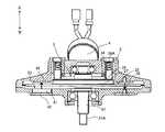
以下、本発明の第1の実施の形態の電動作業機の一例である刈払機1を図1から11を参照して説明する。刈払機1は、ヘッドハウジング2と、ディスクモータ3(図2)と、パイプ部4と、ハンドル部5と、電源部6とから主に構成されており、ヘッドハウジング2に装着される刈刃7で刈払い作業を行う電動作業機である。 Hereinafter, the
ディスクモータ3は、ヘッドハウジング2内に収容されており、出力軸31と、ロータ32と、ステータ33と、ブラシ34とから構成されている。出力軸31は、ヘッドハウジング2に回転可能に支承されている。図2に示すように、出力軸の延出方向を上下方向と定義する。出力軸31の下方側端部には雄ネジ31Aが形成されており、図示せぬ留め具によって刈刃7が固定される。 The disk motor 3 is accommodated in the
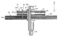
図2及び3に示すように、ロータ32は、図示せぬ整流子が設けられた整流子基板35と、コイル部36と、フランジ37と、絶縁板38と、絶縁シート39と、を有する。整流子基板35は、略円板形状であってその軸芯と出力軸31の軸芯とが一致するように出力軸31に同軸的に固定されている。整流子基板35の中心には、出力軸31が挿入される挿入孔35aが形成され、中心から所定距離離間した位置にはピン40が挿入されるピン孔35bが形成されている。整流子基板35、コイル部36、フランジ37、絶縁板38、及び絶縁シート39は、ピン40によって貫通されると共に互いに接着されている。 As shown in FIGS. 2 and 3, the
コイル部36は、略円板状の4枚のコイルディスク36Aを積層しそれらを接着することにより構成されている。より詳細には、コイル部36は、図4から6に示す一のコイルディスク36A3枚と図7から10に示す他のコイルディスク36A1枚とを積層することにより構成されている。コイルディスク36Aは、出力軸31と直交する面である上面と下面とを有し、それぞれの面は平板状のコイル36Bが設けられる層を構成している(図5)。つまり、コイル部36は4枚8層のコイルディスク36Aから構成されている。詳細な構成は後述する。 The
フランジ37は、出力軸31に同軸的に固定されており、略円筒形状の円筒部37Aと、略円板形状の円板部37Bとから構成されている(図3)。円板部37Bは円筒部37Aから半径方向外方に突出するように設けられており、絶縁板38によって上下方向から挟まれている。円板部37Bはロータ32の強度を上げるために設けられていて、各部材を貫通することにより整流子基板35と各コイル36Bとを電気的に接続するピン40がピン40外周とフランジ37との間に絶縁層を有して貫通している。絶縁シート39は、各コイルディスク36A間及び円板部37Bと絶縁板38との間に設けられている。 The
ステータ33は、磁石41と、ヨーク42とから構成されている(図2)。磁石41は、ヘッドハウジング2に支持され、コイル36Bの後述する直線部36Eと対向する位置に貫通孔36aを中心として円周状且つ、隣接する磁石41とは極が異なるように配置されている(図10の点線)。ヨーク42は、ヘッドハウジング2に支持され、磁石41の磁力を強化するために磁石41の周囲に配置されている。磁石41から発生する磁束は、図2の矢印で示す上下方向にコイル部36を通過する。ブラシ34からコイル部36に電流が供給されている場合は、コイルディスク36A上に磁束の方向と直交するように設けられたコイル36Bに電流が流れることにより、コイル部36に出力軸31を中心とする円周方向にトルクが発生し、ロータ32が回転する。 The
図2に示すように、ブラシ34は、出力軸31を中心に対極に2つ設けられていて、ヘッドハウジング2に支持されている。ブラシ34は、下面が整流子基板35上の図示せぬ整流子と当接するようにバネ34Aによって整流子基板35側(下側)に付勢されている。 As shown in FIG. 2, two
図1に示すように、パイプ部4は、ヘッドハウジング2と電源部6とを接続しており、ヘッドハウジング2と電源部6との間にハンドル部5が配置されている。 As shown in FIG. 1, the
ハンドル部5には、一対の腕部を有するアーム51と、アーム51の一対の腕の先端に配置されたハンドル52と、一方のハンドル52に設けられ、ディスクモータ3の出力調整を行うスロットル53とを有している。 The
電源部6には、電源たるバッテリー61が着脱可能に設けられている。パイプ部4の内部には配線が挿通され、電源部6によりバッテリー61から供給される電力が配線を介してブラシ34に接続されている。 A
刈刃7は、略円板状に構成され、その周縁に鋸歯が形成され、円板状の略中央部分に出力軸31に装着される図示せぬ孔が形成されている。 The
作業者は、スロットル53を操作することによりバッテリー61からコイル36Bに供給する電力を調整することができる。これにより、ディスクモータ3が回転し、その回転力が出力軸31に伝達され刈刃7が回転する。このときのディスクモータ3の回転数については後述するものとする。 The operator can adjust the power supplied from the
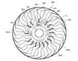
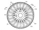
次に図4から11を用いて、コイル部36の詳細な構成について説明する。コイル部36を構成する4枚のコイルディスク36Aのうちの3枚を構成する一のコイルディスク36Aを図4から6に示す。コイルディスク36Aの中心には、出力軸31の軸方向に貫通し出力軸31が挿通される貫通孔36aが形成されている。コイルディスク36Aの上面(図4)及び下面(図5)には、コイル36Bが貫通孔36aを中心に半径方向外方に放射状に延びている。コイル36Bは、一端部36Fを一端とし他端部36Gを他端とする連続する1本のコイルである。コイルディスク36Aの下面にはそれぞれ2つの一端部36F及び他端部36Gが設けられていることから、一のコイルディスク36Aは2本の連続したコイル36Bから構成されている。 Next, the detailed structure of the
図4及び5中のコイル36Bであって、点線で囲まれた領域を部分コイルAと定義する。コイルディスク36Aの上面には、20個の部分コイルAが設けられている。また、コイルディスク36Aの下面にも、20個の部分コイルAが設けられている。このような部分コイルAの配置によって、コイルディスク36Aのコイルパターンが形成される。部分コイルA領域内のコイル36Bは、半径方向内方の内方接続部36Cと、半径方向外方の外方接続部36Dと、内方接続部36Cと外方接続部36Dとを繋ぎ半径方向に直線状に延びる直線部36Eとから構成される。直線部36Eは、本発明の部分コイルに相当し、部分コイルAを構成する直線部36Eが第1部分コイルに相当する。部分コイルA領域内のコイル36Bは、内方接続部36C及び外方接続部36Dにて反対面のコイル36Bと接続している。図6は、コイルディスク36Aを構成する連続した2本のコイル36Bのうちの1本のみを示した図である。上面のコイル36Bを実線で示し、下面のコイル36Bを点線で示す。上面のコイル36Bの内方接続部36Cと下面のコイル36Bの内方接続部36Cとが重なり合っている箇所が上面のコイル36Bと下面のコイル36Bとの接続箇所であり、同様に上面のコイル36Bの外方接続部36Dと下面のコイル36Bの外方接続部36Dとが重なり合っている箇所が上面のコイル36Bと下面のコイル36Bとの接続箇所である。コイルディスク36A上のコイル36Bは、一端部36Fを一端として上面と下面とを交互に行き来してコイルディスク36Aを円周方向に1周した後、他端である他端部36Gに至る。 A region surrounded by a dotted line in the
貫通孔36aの周囲には、貫通孔36aを中心として90°毎に領域36a1、36a2、36a3、36a4が規定されており、各領域36a1、36a2、36a3、36a4には4つ並んだ接続孔36bがそれぞれ形成されている。4つ並んだ接続孔36bのうちの2つの接続孔36bには、一端部36F及び他端部36Gが接続されピン40が挿通される。これにより、一端部36F及び他端部36Gは、ピン40を介して他のコイルディスク36Aと電気的に接続されている。 Around the through
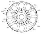
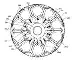
4枚のコイルディスク36Aのうちの残りの1枚を構成する他のコイルディスク36Aを図7から9に示す。一のコイルディスク36A上のコイル36Bの配置と他のコイルディスク36Aのコイル36Bの配置とは略同一であるため、差異点のみ以下に述べる。コイルディスク36A上に部分コイルBを定義する。部分コイルBを構成する直線部36Eは、本発明の第2部分コイルに相当する。他のコイルディスク36A上のコイル36Bは、一のコイルディスク36A上のコイル36Bと比較すると幅が狭く、部分コイルBの領域内におけるコイル36Bの本数が多い(本実施の形態では2本)。図9に示すように、他のコイルディスク36A上のコイル36Bの一端部36Fは、コイルディスク36Aを2周した後に他端部36Gに至っている。図7上には、2つの一端部36F及び他端部36Gが設けられていることから、2本の連続したコイル36Bがコイルディスク36Aを2周している。 7 to 9 show another
ディスクモータ3の回転数は、電源部6からコイル36Bに供給される電圧、ディスクモータ3の電流、磁石41の磁束、ブラシ34の数(極数)、部分コイルA、Bなどによって決定される。なお、本実施の形態における部分コイルとは、磁石41から発生する磁束に対して、直交するように配置されるコイルの纏りのことである。 The number of revolutions of the disk motor 3 is determined by the voltage supplied from the power source 6 to the
本実施の形態は、様々なコイルパターンによってディスクモータ3の回転数をより細かいレンジで調整しようとするものである。ここで、仮想的に図4,5に示す一のコイルディスク36Aを4枚積層することにより8層から構成されるディスクモータ(以下、第1ディスクモータと呼ぶ)と、図6,7に示す他のコイルディスク36Aを4枚積層することにより8層から構成されるディスクモータ(以下、第2ディスクモータと呼ぶ)とを比較する。第1及び第2ディスクモータにおける全導体数は、磁石41上における直線部36Eの数と比例関係にある。具体的には、第1ディスクモータの一のコイルディスク36Aの上面(図4)の全部分コイルA内の直線部36Eの数は20個であり、下面(図5)において直線部36Eの数は20個であるため、1枚当たりのコイルディスク36Aの全導体数は、40(20+20)となる。第1ディスクモータは一のコイルディスク36Aを4枚積層させているため、全導体数は160(40×4)となる。第2ディスクモータの他のコイルディスク36Aは、上面(図6)の全部分コイルA内の直線部36Eの数は40個であり、下面(図7)における直線部36Eの数も40個であって、他のコイルディスクを4枚積層させていることから、第2ディスクモータにおける全導体数は320(80×4)となる。 In the present embodiment, the number of rotations of the disk motor 3 is adjusted in a finer range by various coil patterns. Here, a disk motor (hereinafter referred to as a first disk motor) constituted by eight layers by virtually stacking four
一般的にモータの回転数は磁束を横切る全導体数(磁石41から発生する磁束に直交するように配置される直線部36Eの数(コイル36Bの巻き数、部分コイルAの個数))に反比例するため、第2ディスクモータの回転数N2は第1ディスクモータの回転数N1の半分になる。In general, the rotational speed of the motor is inversely proportional to the total number of conductors crossing the magnetic flux (the number of
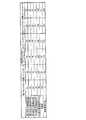
次に、図11を用いて、第1ディスクモータと、第2ディスクモータと、第1の実施の形態のディスクモータ3と、コイルパターン(コイル36Bの巻き数)を変更した第3ディスクモータから第5ディスクモータと、における回転数を比較する。各ディスクモータは、4枚8層のコイルディスクから構成されている。図11では、第1ディスクモータの回転数を100としたときの各ディスクモータにおける回転数及び第1ディスクモータに対する回転数減少率を示す。 Next, referring to FIG. 11, from the first disk motor, the second disk motor, the disk motor 3 according to the first embodiment, and the third disk motor in which the coil pattern (the number of turns of the
上述したように第2ディスクモータでは、全8層の直線部36Eの数が第1ディスクモータの倍となるため、第2ディスクモータの回転数は50となり、回転数減少率は50%となる。従来は、第2ディスクモータのように全層における部分コイルAを変更することによりディスクモータ3の回転数の調整を行っていた。 As described above, in the second disk motor, the number of
第3ディスクモータは、従来の方法によってディスクモータの回転数を変更した場合の他の一例である。第3ディスクモータは、コイルディスク36Aにおいて2本のコイル36Bを3周させたコイルディスク36Aを4枚積層させたものである。第3ディスクモータの回転数は約33となり、回転数減少率は約67%となる。このように、従来の方法によると全層のコイルパターンを変更していたため回転数の微調整が困難であった。 The third disk motor is another example when the rotational speed of the disk motor is changed by a conventional method. The third disk motor is formed by stacking four
本実施の形態のディスクモータ3では、第1から3枚目(1から6層目)の直線部36Eの数は40であり、第4枚目(7及び8層目)のみ直線部36Eの数が80となっているため、全層の直線部36Eの合計は200となる。従って、本実施の形態のディスクモータ3の回転数は80となり、回転数減少率は20%となる。そのため、従来のディスクモータの回転数の変更方法と比べて回転数減少率が低くなり、ディスクモータ3の回転数の微調整が可能となる。 In the disk motor 3 of the present embodiment, the number of first to third (first to sixth)
第4ディスクモータは、本実施の形態における一のコイルディスク36A2枚と他のコイルディスク36A2枚とを積層したディスクモータである。第4ディスクモータの場合は、回転数は約67となり、回転数減少率は約33%となる。第5ディスクモータは、本実施の形態における一のコイルディスク36A1枚と他のコイルディスク36A3枚とを積層したディスクモータである。第5ディスクモータの場合は、回転数は約57となり、回転数減少率は約43%となる。第4ディスクモータ及び第5ディスクモータについても本実施の形態と同様の効果を得ることができる。 The fourth disk motor is a disk motor in which one coil disk 36A2 and another coil disk 36A2 in the present embodiment are stacked. In the case of the fourth disk motor, the rotational speed is about 67, and the rotational speed reduction rate is about 33%. The fifth disk motor is a disk motor in which one coil disk 36A1 and another coil disk 36A3 in the present embodiment are stacked. In the case of the fifth disk motor, the rotational speed is about 57, and the rotational speed reduction rate is about 43%. The same effects as in the present embodiment can be obtained for the fourth disk motor and the fifth disk motor.
また、本実施の形態では、コイル部36はコイルディスク36Aを4枚積層した状態で、出力軸31と直交しコイル部36の中心を通る中心軸E(図5)に対して軸対称となるように構成されている。より詳細には、1枚目のコイルディスク36Aでは一端部36F及び他端部36Gは領域36a1、36a2に接続されていて、2枚目のコイルディスク36Aでは一端部36F及び他端部36Gは領域36a2、36a3に接続されていて、3枚目のコイルディスク36Aでは一端部36F及び他端部36Gは領域36a3、36a4に接続されていて、4枚目のコイルディスク36Aでは一端部36F及び他端部36Gは領域36a4、36a1に接続されている。 Further, in the present embodiment, the
図4に示す部分コイルAのうち、内方接続部36Cが他の部分コイルAの内方接続部36Cと直接接続しているもの(以下、直接接続部36Hという)が領域36a1、36a4の直近に設けられている。これについても同様に、1枚目のコイルディスク36Aでは直接接続部36Hは領域36a4、36a1の近傍に位置し、2枚目のコイルディスク36Aでは直接接続部36Hは領域36a1、36a2の近傍に位置し、3枚目のコイルディスク36Aでは直接接続部36Hは領域36a2、36a3の近傍に位置し、4枚目のコイルディスク36Aでは直接接続部36Hは領域36a3、36a4の近傍に位置している。一端部36F、他端部36G、及び直接接続部36H以外の部分コイルAの形状は同一であることから、コイル部36は、コイルディスク36Aが4枚積層された状態で中心軸Eに対して軸対称になるように構成されている。これにより、コイルディスク36Aにおける重量バランスが均等となり、ディスクモータ3動作時の振動などを防止することができる。 Among the partial coils A shown in FIG. 4, the one in which the
本実施の形態によるディスクモータを搭載した電動作業機では、一のコイルディスク36Aの部分コイルAの本数と他のコイルディスク36Aの部分コイルBの本数を互いに異ならせることにより、磁石41上を通過する部分コイルを自在に調整することができる。これにより、ディスクモータ3の回転数の微調整が可能となり、ディスクモータ3の設計の自由度を向上させることができる。 In the electric working machine equipped with the disk motor according to the present embodiment, the number of the partial coils A of one
また、本実施の形態によるディスクモータを搭載した電動作業機では、部分コイルAは部分コイルBよりも幅が広いため、部分コイルAを構成するコイル36Bは抵抗が少なくなるとともに放熱性に優れることにより、ディスクモータ3の出力を上げることが可能となる。 Moreover, in the electric working machine equipped with the disk motor according to the present embodiment, the partial coil A is wider than the partial coil B, so that the
次に、本発明の第2の実施の形態のディスクモータ103について図12から14に基づいて説明する。第2の実施の形態では、コイルディスク136A上の部分コイルが第1の実施の形態のディスクモータ3と異なるため、以下、差異点についてのみ説明する。 Next, a disk motor 103 according to a second embodiment of the present invention will be described with reference to FIGS. In the second embodiment, since the partial coil on the
コイルディスク136A上には、連続する2本のコイル136Bが設けられていて、それぞれのコイル136Bは一端部136F、136F´と他端部136G、136G´とを有する。また、コイルディスク136Aには、部分コイルCと部分コイルDとが規定されていて、第1の実施の形態と同様に貫通孔136a及び接続孔136bが形成される。 Two
部分コイルCと部分コイルDは、コイルディスク136Aの円周方向に交互に配置される。部分コイルC及びD内の領域のコイル136Bは、半径方向内方の内方接続部136Cと、半径方向外方の外方接続部136Dと、内方接続部136Cと外方接続部136Dとを繋ぎ半径方向に直線状に延びる直線部136Eとから構成される。上面のコイル136Bと下面のコイル136Bとは、内方接続部136C及び外方接続部136Dで互いに接続されている。 The partial coil C and the partial coil D are alternately arranged in the circumferential direction of the
部分コイルCではコイル136Bの本数が1本であり、部分コイルDではコイル136Bの本数が2本である。これは、図13に示す2つの一端部136F、136F´のうち、複数の部分コイルCにより構成されるコイル136Bの一端部136F´はコイルディスク136Aを2周した後に他端部136G´に至っていて、複数の部分コイルDにより構成されるコイル136Bの一端部136Fはコイルディスク136Aを1周した後に他端部136Gに至っているからである。これにより、部分コイルC内のコイル136Bの幅は、部分コイルD内のコイル136Bの幅の約2倍となっている。このような構成によると、コイルディスク136Aの上面における直線部136Eの数は30個となり、下面における直線部の数も30個となるため、コイルディスク136A上の全直線部の数は60個となる。 In the partial coil C, the number of
図14に、第2の実施の形態のコイルディスク136Aを用いた第6ディスクモータ、第7ディスクモータの回転数と、第1ディスクモータの回転数と、を比較した表を示す。 FIG. 14 shows a table comparing the rotation speeds of the sixth and seventh disk motors using the
第6ディスクモータは、第1の実施の形態における一のコイルディスク36A3枚と第2の実施の形態のコイルディスク136A1枚とを積層したディスクモータである。第6ディスクモータの場合は、回転数は約89となり、回転数減少率は約11%となる。第7ディスクモータは、第1の実施の形態における一のコイルディスク36A1枚と第2の実施の形態のコイルディスク136A3枚とを積層したディスクモータである。第7ディスクモータの場合は、回転数は約73となり、回転数減少率は約27%となる。このように、第2の実施の形態のコイルディスク136Aを用いることで、ディスクモータ103の回転数をより詳細に調整することが可能となる。 The sixth disk motor is a disk motor in which three
本実施の形態によるディスクモータでは、1枚のコイルディスク136A上における部分コイルCの本数と部分コイルDの本数とを互いに異ならせることにより、磁石41上を通過する部分コイルを自在に調整することができる。これにより、第1の実施の形態のディスクモータ3と比較すると、ディスクモータ103の回転数の更なる微調整が可能となり、ディスクモータ103の設計の自由度を大幅に向上させることができる。また、部分コイルDは部分コイルCよりも幅が広いため、部分コイルDを構成するコイル36Bは抵抗が少なくなるとともに放熱性に優れることにより、ディスクモータ3の出力を上げることが可能となる。 In the disk motor according to the present embodiment, the number of partial coils C and the number of partial coils D on one
上述したような構成によると、部分コイルCと部分コイルDとが互いに隣接するように交互に配置されていることにより、コイルディスク136A全体の重量バランスの均一化が可能となり、ディスクモータ103動作時の振動などを防止することができる。さらに、ディスクモータ103のバランス調整等の作業が容易になる。 According to the configuration as described above, the partial coils C and the partial coils D are alternately arranged so as to be adjacent to each other, whereby the weight balance of the
本発明によるディスクモータ及び電動作業機は上述した実施の形態に限定されず、たとえば特許請求の範囲に記載された発明の要旨の範囲内で種々の変更が可能である。 The disk motor and the electric working machine according to the present invention are not limited to the above-described embodiments, and various modifications are possible within the scope of the gist of the invention described in the claims, for example.
本実施の形態では、コイル部36は4枚のコイルディスク36A、136Aによって構成されたが、コイルディスクの枚数及び層数はこれに限られない。コイルディスク1枚でコイル部を構成してもよく、4枚以上のコイルディスクを積層してもよい。また、コイル36Bは、コイルディスク36A、136Aの両面に設けられていたが、上面又は下面の一方の面にのみ設けてもよい。これにより、コイルディスク36A、136A上の直線部36E、136Eの数をさらに減らすことができるため、ディスクモータ3、103の回転数をより詳細に調整することが可能となる。 In the present embodiment, the
また、第1の実施の形態ではコイル部36を構成する複数のコイルディスク36Aのうち一のコイルディスク36Aではコイル36Bを1周させ、他のコイルディスク36Aではコイル36Bを2周させたが、コイルの周回数はこれに限られない。一のコイルディスク36Aの周回数と他のコイルディスク36Aの周回数とが異なっていれば本発明の効果を得ることができる。 In the first embodiment, among the plurality of
また、第2の実施の形態では、コイルディスク36A上の一のコイル36Bは1周であって、他のコイルは2周であったが、コイルの周回数はこれに限られない。同一のコイルディスク36Aで一のコイル36Bと他のコイル36Bの周回数が異なっていれば本発明の効果を得ることができる。 In the second embodiment, one
また、本実施の形態では、コイルディスク36Aは2本の連続したコイル36Bにより構成されたが、コイル36Bの本数はこれに限られない。コイルディスク36Aを3本の連続したコイルで構成しても良く、またそれ以上の本数のコイルで構成してもよい。 In the present embodiment, the
また、本実施の形態の部分コイルA,B,C,Dは、貫通孔36a、136aを中心として半径方向に放射状に設けられていたがこの形状に限られない。 Further, the partial coils A, B, C, and D of the present embodiment are provided radially in the radial direction with the through
また、本実施の形態では、電動作業機の一例として刈払機1を用いたが、ディスクモータを搭載した電動工具であればこれに限られない。例えば、ディスクモータを搭載したベルトサンダーやロータリバンドソーなどの電動工具に適用しても良い。 In the present embodiment, the
1・・刈払機 2・・ヘッドハウジング 3,103・・ディスクモータ 4・・パイプ部 5・・ハンドル部 6・・電源部 7・・刈刃 31・・出力軸 32・・ロータ 33・・ステータ 34・・ブラシ 35・・整流子基板 36・・コイル部 36A、136A・・コイルディスク 36B、136B・・コイル 37・・フランジ 38・・絶縁板 39・・絶縁シート 41・・磁石 42・・ヨーク A、B、C、D・・部分コイル1..
Claims (6)
Translated fromJapanese略円板状であって、前記出力軸に同軸的に固定され、前記出力軸の回転中心から半径方向外方に放射状に延びる複数の部分コイルが接続されたことにより構成されるコイルが設けられた少なくとも2層からなるコイルディスクと、
前記コイルに電流を供給する電流供給部と、
前記コイルに対向するように配置される磁石と、を有し、
前記コイルディスクのうちの一の層に形成された第1部分コイルの総数と他の層に形成された第2部分コイルの総数とは互いに異なることを特徴とするディスクモータ。An output shaft;
A substantially disk-shaped coil is provided which is coaxially fixed to the output shaft and is configured by connecting a plurality of partial coils extending radially outward from the rotation center of the output shaft. A coil disk comprising at least two layers;
A current supply for supplying current to the coil;
A magnet arranged to face the coil,
The disk motor according to claim 1, wherein the total number of first partial coils formed on one layer of the coil disk is different from the total number of second partial coils formed on another layer.
Priority Applications (4)
| Application Number | Priority Date | Filing Date | Title |
|---|---|---|---|
| JP2010221955AJP5534337B2 (en) | 2010-09-30 | 2010-09-30 | Disc motor and electric working machine |
| DE102011113815ADE102011113815A1 (en) | 2010-09-30 | 2011-09-14 | DISK RUNNING ENGINE AND ELECTRICAL WORKING MACHINE EQUIPPED WITH THIS |
| CN201110276181.7ACN102447330B (en) | 2010-09-30 | 2011-09-16 | Disc-type electric motor and the electric working machine being equipped with this disc-type electric motor |
| US13/237,201US8823242B2 (en) | 2010-09-30 | 2011-09-20 | Disc motor and electric working machine equipped with disc motor |
Applications Claiming Priority (1)
| Application Number | Priority Date | Filing Date | Title |
|---|---|---|---|
| JP2010221955AJP5534337B2 (en) | 2010-09-30 | 2010-09-30 | Disc motor and electric working machine |
Publications (2)
| Publication Number | Publication Date |
|---|---|
| JP2012080631A JP2012080631A (en) | 2012-04-19 |
| JP5534337B2true JP5534337B2 (en) | 2014-06-25 |
Family
ID=45832743
Family Applications (1)
| Application Number | Title | Priority Date | Filing Date |
|---|---|---|---|
| JP2010221955AExpired - Fee RelatedJP5534337B2 (en) | 2010-09-30 | 2010-09-30 | Disc motor and electric working machine |
Country Status (4)
| Country | Link |
|---|---|
| US (1) | US8823242B2 (en) |
| JP (1) | JP5534337B2 (en) |
| CN (1) | CN102447330B (en) |
| DE (1) | DE102011113815A1 (en) |
Families Citing this family (8)
| Publication number | Priority date | Publication date | Assignee | Title |
|---|---|---|---|---|
| US8193781B2 (en)* | 2009-09-04 | 2012-06-05 | Apple Inc. | Harnessing power through electromagnetic induction utilizing printed coils |
| JP5751444B2 (en)* | 2011-04-26 | 2015-07-22 | 日立工機株式会社 | Disc motor and electric working machine |
| CN111697732B (en)* | 2013-06-27 | 2023-03-24 | 卢万天主教大学 | Winding for a rotating electrical machine and method for designing such a winding |
| WO2015111579A1 (en)* | 2014-01-21 | 2015-07-30 | 株式会社羽野製作所 | Power generation device, armature structure for power generation device, and method for manufacturing armature |
| US10277084B1 (en) | 2016-10-19 | 2019-04-30 | Waymo Llc | Planar rotary transformer |
| US10530209B2 (en)* | 2016-10-28 | 2020-01-07 | Waymo Llc | Devices and methods for driving a rotary platform |
| US10135310B2 (en)* | 2017-01-11 | 2018-11-20 | Infinitum Electric Inc. | System and apparatus for modular axial field rotary energy device |
| WO2019044900A1 (en)* | 2017-08-29 | 2019-03-07 | 株式会社ExH | Electric power transmission system, and manufacturing method for electric power transmission system |
Family Cites Families (15)
| Publication number | Priority date | Publication date | Assignee | Title |
|---|---|---|---|---|
| JPS5866849U (en)* | 1981-10-29 | 1983-05-07 | 株式会社リコー | Rotating disc armature |
| JPH01126142A (en)* | 1987-11-06 | 1989-05-18 | Sony Corp | Motor coil |
| DE3821050A1 (en)* | 1988-06-22 | 1989-12-28 | Thomson Brandt Gmbh | TACHOGENERATOR |
| JPH11136990A (en)* | 1997-10-31 | 1999-05-21 | Matsushita Electric Ind Co Ltd | Rotary magnetic disc drive |
| US6040650A (en)* | 1998-06-30 | 2000-03-21 | Rao; Dantam K. | Stator with coplanar tapered conductors |
| US7112910B2 (en) | 2001-06-26 | 2006-09-26 | Rotys Inc. | Brushless DC electric motor |
| GB2378046A (en)* | 2001-07-18 | 2003-01-29 | Turbo Genset Company Ltd | Cooling flow in discoid stator windings |
| JP3636700B2 (en) | 2002-04-01 | 2005-04-06 | 公明 岩谷 | Rotor structure |
| JP2006081269A (en)* | 2004-09-08 | 2006-03-23 | Matsushita Electric Ind Co Ltd | Multilayer coil and motor using the same |
| US8058762B2 (en)* | 2005-01-19 | 2011-11-15 | Daikin Industries, Ltd. | Rotor, axial gap type motor, method of driving motor, and compressor |
| DE102006012215A1 (en)* | 2006-03-16 | 2007-09-20 | Mtu Aero Engines Gmbh | Transverse flux machine and turbomachinery with such Transversalflussmaschie |
| US7375449B2 (en)* | 2006-08-17 | 2008-05-20 | Butterfield Paul D | Optimized modular electrical machine using permanent magnets |
| JP4940187B2 (en)* | 2008-06-24 | 2012-05-30 | 公明 岩谷 | Coil device |
| US8193678B2 (en)* | 2009-09-07 | 2012-06-05 | Sunonwealth Electric Machine Industry Co., Ltd. | Coil unit for motor stator |
| CN102055267B (en)* | 2009-11-09 | 2012-12-12 | 台达电子工业股份有限公司 | Fan and three-phase motor thereof |
- 2010
- 2010-09-30JPJP2010221955Apatent/JP5534337B2/ennot_activeExpired - Fee Related
- 2011
- 2011-09-14DEDE102011113815Apatent/DE102011113815A1/ennot_activeCeased
- 2011-09-16CNCN201110276181.7Apatent/CN102447330B/ennot_activeExpired - Fee Related
- 2011-09-20USUS13/237,201patent/US8823242B2/enactiveActive
Also Published As
| Publication number | Publication date |
|---|---|
| CN102447330A (en) | 2012-05-09 |
| DE102011113815A1 (en) | 2012-04-05 |
| JP2012080631A (en) | 2012-04-19 |
| CN102447330B (en) | 2015-08-12 |
| US20120080974A1 (en) | 2012-04-05 |
| US8823242B2 (en) | 2014-09-02 |
Similar Documents
| Publication | Publication Date | Title |
|---|---|---|
| JP5534337B2 (en) | Disc motor and electric working machine | |
| JP5880817B2 (en) | Disk motor and electric working machine equipped with the same | |
| US9570952B2 (en) | Disk motor, electric working machine including disk motor and method for manufacturing disk motor | |
| TWI514726B (en) | A manufacturing method of a coupling device and a coupling device | |
| JP5817964B2 (en) | Disk motor and electric working machine equipped with the same | |
| JP5534338B2 (en) | Disc motor and electric working machine | |
| JP2012161136A (en) | Disk motor and electric working machine | |
| JP5751444B2 (en) | Disc motor and electric working machine | |
| JP5651940B2 (en) | Electric motor and work machine | |
| JP5790936B2 (en) | DISK MOTOR, ELECTRIC WORKING MACHINE HAVING THE SAME, AND DISK MOTOR BALANCE ADJUSTING METHOD | |
| US12176754B2 (en) | Electric machine and magnetic field portion | |
| JP2013099009A (en) | Disc motor and electric working machine including the same | |
| JP5854185B2 (en) | Disk motor and electric working machine equipped with the same | |
| JP5794417B2 (en) | Disk motor and electric working machine equipped with the same | |
| JP2013017312A (en) | Disk motor and electric operating machine having the same | |
| JP5737499B2 (en) | DISK MOTOR, ELECTRIC WORKING MACHINE HAVING THE SAME, AND DISK MOTOR MANUFACTURING METHOD | |
| JP2022065731A (en) | Motor and work machine | |
| JP5904321B2 (en) | Disk motor and electric working machine equipped with the same | |
| JP2017158421A (en) | Brushless motor stator and brushless motor |
Legal Events
| Date | Code | Title | Description |
|---|---|---|---|
| A621 | Written request for application examination | Free format text:JAPANESE INTERMEDIATE CODE: A621 Effective date:20130401 | |
| A977 | Report on retrieval | Free format text:JAPANESE INTERMEDIATE CODE: A971007 Effective date:20140312 | |
| TRDD | Decision of grant or rejection written | ||
| A01 | Written decision to grant a patent or to grant a registration (utility model) | Free format text:JAPANESE INTERMEDIATE CODE: A01 Effective date:20140403 | |
| R150 | Certificate of patent or registration of utility model | Ref document number:5534337 Country of ref document:JP Free format text:JAPANESE INTERMEDIATE CODE: R150 | |
| A61 | First payment of annual fees (during grant procedure) | Free format text:JAPANESE INTERMEDIATE CODE: A61 Effective date:20140416 | |
| S533 | Written request for registration of change of name | Free format text:JAPANESE INTERMEDIATE CODE: R313533 | |
| R350 | Written notification of registration of transfer | Free format text:JAPANESE INTERMEDIATE CODE: R350 | |
| LAPS | Cancellation because of no payment of annual fees |