JP5534327B2 - Electric tool - Google Patents
Electric toolDownload PDFInfo
- Publication number
- JP5534327B2 JP5534327B2JP2010115152AJP2010115152AJP5534327B2JP 5534327 B2JP5534327 B2JP 5534327B2JP 2010115152 AJP2010115152 AJP 2010115152AJP 2010115152 AJP2010115152 AJP 2010115152AJP 5534327 B2JP5534327 B2JP 5534327B2
- Authority
- JP
- Japan
- Prior art keywords
- motor
- load
- increase rate
- unit
- control
- Prior art date
- Legal status (The legal status is an assumption and is not a legal conclusion. Google has not performed a legal analysis and makes no representation as to the accuracy of the status listed.)
- Expired - Fee Related
Links
Images


Classifications
- B—PERFORMING OPERATIONS; TRANSPORTING
- B25—HAND TOOLS; PORTABLE POWER-DRIVEN TOOLS; MANIPULATORS
- B25F—COMBINATION OR MULTI-PURPOSE TOOLS NOT OTHERWISE PROVIDED FOR; DETAILS OR COMPONENTS OF PORTABLE POWER-DRIVEN TOOLS NOT PARTICULARLY RELATED TO THE OPERATIONS PERFORMED AND NOT OTHERWISE PROVIDED FOR
- B25F5/00—Details or components of portable power-driven tools not particularly related to the operations performed and not otherwise provided for
Landscapes
- Engineering & Computer Science (AREA)
- Mechanical Engineering (AREA)
- Portable Power Tools In General (AREA)
- Control Of Motors That Do Not Use Commutators (AREA)
- Details Of Spanners, Wrenches, And Screw Drivers And Accessories (AREA)
Description
Translated fromJapanese本発明は、電動工具に関し、特に、ソフトスタート制御を行う電動工具に関する。 The present invention relates to a power tool, and more particularly to a power tool that performs soft start control.
モータを備えた装置においては、モータの起動時に、モータの回転数に対するモータへの印加電圧の大きさに応じた起動電流が発生する。多大な起動電流が発生すると温度上昇に伴うモータや回路部の焼損が生じる虞があるため、モータの起動時にモータへ印加する電圧を徐々に増加させるソフトスタート制御を行う電動工具が知られている(例えば、特許文献1参照)。 In an apparatus equipped with a motor, when the motor is started, a starting current is generated according to the magnitude of the voltage applied to the motor with respect to the rotational speed of the motor. Electric tools that perform soft start control that gradually increases the voltage applied to the motor at the time of motor startup are known because there is a risk of burning the motor and the circuit part due to temperature rise when a large startup current is generated (For example, refer to Patent Document 1).
上記したように、起動電流の大きさは、モータの回転数に対するモータへの印加電圧に依存しているため、一般には、負荷が小さい場合には小さな起動電流が発生し、負荷が大きい場合には大きな起動電流が発生することとなる。従って、小ネジのような小さな負荷の場合には、多大な起動電流が発生する虞は少ない。 As described above, since the magnitude of the starting current depends on the voltage applied to the motor with respect to the number of rotations of the motor, generally, a small starting current is generated when the load is small, and when the load is large. A large starting current is generated. Therefore, in the case of a small load such as a small screw, there is little possibility that a large starting current is generated.
しかしながら、特許文献1に記載の電動工具では、負荷が小さい場合でも、モータへ印加する電圧を一定の増加率で徐々に増加させているため、モータの起動に必要以上の時間がかかると同時に、トリガ操作に対するモータへの電力供給の追従性が悪くなってしまう。特に、トリガのオン・オフの繰り返しにより小ネジを締結するような場合には、ユーザにとって非常に使用感の悪いものとなってしまう。一方で、特許文献1に記載の電動工具では、負荷が想定以上の大きさであった場合には、ソフトスタート制御を行っても多大な起動電流が発生してしまい、温度上昇に伴うモータや回路部の焼損が生じる虞がある。 However, in the electric power tool described in Patent Document 1, since the voltage applied to the motor is gradually increased at a constant increase rate even when the load is small, it takes more time than necessary to start the motor. The followability of the power supply to the motor with respect to the trigger operation is deteriorated. In particular, when the small screw is fastened by repeating the on / off of the trigger, the feeling of use is very bad for the user. On the other hand, in the electric power tool described in Patent Document 1, when the load is larger than expected, a great start-up current is generated even if soft start control is performed, There is a possibility that the circuit portion may be burned out.
本発明は、斯かる実情に鑑み、負荷の大きさに応じた適切なソフトスタート制御を行うことの可能な電動工具を提供しようとするものである。 In view of such circumstances, the present invention intends to provide an electric tool capable of performing appropriate soft start control according to the magnitude of a load.
上記課題を解決するために、本発明は、モータと、前記モータに電圧を印加する電圧印加部と、前記電圧印加部から前記モータへの電力供給の開始を指示するトリガと、前記トリガからの指示に応じて、前記モータに印加される電力が目標値に達するまで、所定の増加率で前記モータに前記電圧を印加するように前記電圧印加部を制御する制御部と、を備えた電動工具であって、前記モータにかかる負荷の大きさを検出する負荷検出部を更に備え、前記制御部は、前記負荷の大きさに応じて前記所定の増加率を変更することを特徴とする電動工具を提供している。 In order to solve the above problems, the present invention relates to a motor, a voltage application unit that applies a voltage to the motor, a trigger that instructs the start of power supply from the voltage application unit to the motor, And a control unit that controls the voltage application unit to apply the voltage to the motor at a predetermined increase rate until the electric power applied to the motor reaches a target value in accordance with an instruction. The power tool further includes a load detection unit that detects a magnitude of the load applied to the motor, and the control unit changes the predetermined increase rate according to the magnitude of the load. Is provided.
このような構成によれば、負荷の大きさに応じてモータに印加される電圧の増加率を変更するので、負荷の大きさに応じた適切なソフトスタート制御を行うことが可能となる。 According to such a configuration, since the rate of increase of the voltage applied to the motor is changed according to the size of the load, it is possible to perform appropriate soft start control according to the size of the load.
また、前記制御部は、前記負荷の大きさが所定の閾値以下の場合に前記増加率を上げることが好ましい。 Moreover, it is preferable that the said control part raises the said increase rate, when the magnitude | size of the said load is below a predetermined threshold value.
このような構成によれば、負荷の大きさが所定の閾値以下の場合、すなわち、軽負荷の場合には増加率を上げるので、モータに供給する電力を目標値まで増加させるための時間を短縮することが可能となる。更に、モータを停止状態から高速回転まで短時間で加速することができるので、トリガ操作に対するモータへの電力供給の追従性を大幅に改善することが可能となる。 According to such a configuration, when the load is below a predetermined threshold, that is, when the load is light, the increase rate is increased, so the time for increasing the power supplied to the motor to the target value is shortened. It becomes possible to do. Furthermore, since the motor can be accelerated in a short time from the stopped state to the high speed rotation, it is possible to greatly improve the followability of the power supply to the motor with respect to the trigger operation.
また、前記モータの回転数又は前記モータに流れる電流を検出する回転数・電流検出部を更に備え、前記制御部は、前記モータへの電力の供給開始から所定時間経過後における前記回転数又は前記電流が所定の閾値に達した場合に前記所定の増加率を変更することが好ましい。 The motor further includes a rotation speed / current detection unit that detects a rotation speed of the motor or a current flowing through the motor, and the control unit is configured to detect the rotation speed or the power after a predetermined time has elapsed from the start of power supply to the motor. The predetermined increase rate is preferably changed when the current reaches a predetermined threshold.
このような構成によれば、回転数又は電流を検出することにより、容易に負荷の大きさを判断することが可能となる。 According to such a configuration, the magnitude of the load can be easily determined by detecting the rotation speed or the current.
また、前記制御部は、前記閾値を複数設定可能であり、前記回転数又は前記電流が各閾値に達する毎に前記増加率を変更することが好ましい。 Moreover, the said control part can set two or more said threshold values, It is preferable to change the said increase rate, whenever the said rotation speed or the said current reaches each threshold value.
このような構成によれば、負荷の大きさに応じたより適切なソフトスタート制御を行うことが可能となる。 According to such a configuration, it is possible to perform more appropriate soft start control according to the magnitude of the load.
また、前記モータへの電力供給のオン・オフを切り替えるスイッチを更に有し、前記制御部は、PWM制御により前記スイッチを制御することが好ましい。Further, it is preferable that a switch forswitching on / off of power supply to the motor is further provided, and the control unit controls the switch by PWM control.
また、前記モータへの電力供給のオン・オフを切り替えるスイッチを更に有し、前記制御部は、サイリスタ位相制御により前記スイッチを制御することが好ましい。
Further, it is preferable that a switch forswitching on / off of power supply to the motor is further provided, and the control unit controls the switch by thyristor phase control.
本発明の電動工具によれば、負荷の大きさに応じた適切なソフトスタート制御を行うことが可能となる。 According to the electric tool of the present invention, it is possible to perform appropriate soft start control according to the magnitude of the load.
以下、本発明の実施の形態を図1〜図8を参照して説明する。なお、図中において、同一の機能を有する部材には同一の符号を付し、その繰り返しの説明は省略する。 Hereinafter, embodiments of the present invention will be described with reference to FIGS. In the drawings, members having the same function are denoted by the same reference numerals, and repeated description thereof is omitted.
図1は、本実施の形態に係る電動工具としてのドライバドリル1の一部断面図である。本実施の形態では、図1に示すように、紙面上側を上側、紙面下側を下側、紙面右側を前側、紙面左側を後側、紙面奥側を左側、紙面手前側を右側として説明する。 FIG. 1 is a partial cross-sectional view of a driver drill 1 as an electric tool according to the present embodiment. In the present embodiment, as shown in FIG. 1, the upper side of the page is the upper side, the lower side of the page is the lower side, the right side of the page is the front side, the left side of the page is the rear side, the back side of the page is the left side, and the front side of the page is the right side. .
ドライバドリル1は、電池パック2と、ハウジング3と、チャック4と、を備えている。 The driver drill 1 includes a
電池パック2は、複数の二次電池を備えており、ハウジング3と接続されることによりハウジング3側へ電力供給可能となる。本実施の形態では、定格出力電圧3.6Vのリチウムイオン電池が4個直列に接続されているものとする。なお、二次電池として、ニッケルカドミウム電池やニッケル水素電池を用いることもできるが、ニッケルカドミウム電池やニッケル水素電池と比較して約3倍のエネルギー密度を持ち、小形軽量であるという点で、リチウムイオン電池を用いることが好ましい。また、電池パック2の代わりに、商用電源からハウジング3側へ電力を供給する構成であってもよい。 The
ハウジング3は、合成樹脂材料によって一体的に成型されたハンドルハウジング部5及び胴体ハウジング部6から構成されている。 The housing 3 includes a
ハンドルハウジング部5は、その下端部に電池パック2を着脱可能であり、また、ハンドルハウジング部5内には、制御回路部51及びトリガ部52が設けられている。 The
胴体ハウジング部6は、その後端部に吸気口61が形成されており、また、胴体ハウジング部6内には、後側から順にインバータ回路部62と、モータ63と、防塵カバー64と、冷却用ファン65と、正逆切替レバー66と、減速機構部67と、クラッチ機構部68と、スピンドル69と、が配置されている。 The fuselage housing part 6 has an
制御回路部51は、インバータ回路部62を制御するためのものであって、ハンドルハウジング部5内の下端部に前後左右方向に延在するように配置されている。 The
トリガ部52は、ハンドルハウジング部5の上端付近から突出し、バネによって付勢されたトリガ操作部52aを備えており、トリガ部52は、トリガ操作部52aが押し込まれた量に応じた電力供給の目標値を示す目標値信号を制御回路部51に出力する。制御回路部51は、目標値信号に基づき、インバータ回路部62を駆動するためのPWM駆動信号を生成する。制御回路部51によるPWM駆動信号の生成については後述する。 The
インバータ回路部62は、円板状の回路基板上に絶縁ゲート・バイポーラ・トランジスタ(IGBT)からなるスイッチング素子Q1〜Q6(図3参照)を備えており、スイッチング素子Q1〜Q6のゲートは、制御回路部51(後述する制御信号出力回路518)に、コレクタ又はエミッタは、モータ63(後述するテータ巻線63b)にそれぞれ接続されている。インバータ回路部62は、制御回路部51から出力されたPWM駆動信号に基づいてスイッチング素子Q1〜Q6をオン・オフすることにより、電池パック2から供給された直流電圧を交流電圧に変換してモータ63に出力するが、詳細は後述する。なお、本実施の形態では、スイッチング素子Q1〜Q6として、絶縁ゲート・バイポーラ・トランジスタ(IGBT)を用いているが、電界効果トランジスタ(MOSFET)等を用いてもよい。 The
次に、図2を用いてモータ63の構成について説明する。図2は、図1のII−II断面図である。本実施の形態では、モータ63として、内部磁石配置形の3相ブラシレス直流モータを用いており、モータ63は、ステータ63aと、三相(U、V、W)のステータ巻線63bと、ロータ63cと、を備えている。 Next, the configuration of the
ステータ63aは、円筒状の外形を有しており、円筒部63dと、及び円筒部63dから半径方向内側に向かって延出する6つのティース部63eと、を備えている。 The
三相(U、V、W)のステータ巻線63bは、互いにスター結線されており、また、各相(U、V、W)のステータ巻線63b(U、V、W)は、樹脂材料からなる絶縁層63f(図1参照)を介して対向する2つのティース部63eに巻回されている。ロータ63cは、ティース部63eの半径方向内側に配置されており、出力軸63gと、永久磁石63hと、を備えている。永久磁石63hは、出力軸63gの軸方向に延びるN極及びS極の磁石が回転方向に90度毎に交互に配置された構成となっている。 The three-phase (U, V, W) stator winding 63b is star-connected to each other, and each phase (U, V, W) stator winding 63b (U, V, W) is made of resin material. It is wound around the two
ロータ63cの近傍には、3つのホールIC63i−63kが回転方向に60度毎に配置されており、ホールIC63i−63kは、電磁結合方式により永久磁石63hからの磁力を検出し、回転位置検出信号を出力する。なお、ホールIC63i−63kを備えずに、フィルタを通してステータ巻線63bの誘起電力(逆起電力)を論理信号として取出すことにより回転位置を検出するセンサレス方式を採用することも可能である。 In the vicinity of the
図1に戻って全体構成の説明を続ける。図1に示すように、ステータ63aの後端部は、インバータ回路部62の円板状の回路基板によって全面的に覆われており、前端部は、防塵カバー64によって覆われている。このように、インバータ回路部62、ステータ63a、及び、防塵カバー64は、協働してロータ63cを閉塞又は密封する防塵構造(密閉構造)を形成しており、これにより、ロータ63cへの粉塵の侵入を防止している。 Returning to FIG. 1, description of the entire configuration will be continued. As shown in FIG. 1, the rear end portion of the
また、ハンドルハウジング部5と胴体ハウジング部6とは、モータ63の回転出力軸63gを通る鉛直面で左右に2分割可能に構成されており、胴体ハウジング部6には、複数のステータ保持部(図示せず)が形成されている。組み立て時には、ステータ63aがステータ保持部に保持されるように、左右いずれか一方のハンドルハウジング部5及び胴体ハウジング部6(以下、ハウジング部材)にモータ63等を組み込んだ後に他方のハウジング部材を重ね、ネジ締め等で双方のハウジング部材を締結させる。 Further, the
モータ63の前端部側には回転出力軸63gと同軸上に冷却用ファン65が設けられている。胴体ハウジング部6の冷却用ファン65近傍には、図示しない排気口が形成されており、胴体ハウジング部6の後端部側には吸気口61が形成されている。この吸気口61から排気口に至る通路が流通路Pを形成しており、流通路Pを空気が通過することにより、スイッチング素子Q1〜Q6及びステータ巻線63bの温度上昇を抑制している。また、スイッチング素子Q1〜Q6の発熱が大きくなった場合には、冷却用ファン55から流通路Pに冷却用空気を送り出すことで、スイッチング素子Q1〜Q6を強制的に冷却することも可能である。 On the front end side of the
減速機構部67は、モータ63の回転出力軸63gから出力された回転力(回転数)を減速させるためのものであって、例えば、周知の2段の遊星歯車減速機構(図示せず)から構成されている。 The
クラッチ機構部68は、減速機構部67の出力軸とスピンドル69とを結合させる一方で結合の解除も行うものであって、モード切替及びトルク設定のためのダイヤル68aを備えている。本実施の形態では、ダイヤル68aを回転させることにより、ドライバモード及びドリルモードのいずれかを選択することができ、更に、ドライバモードの中では、被加工部材からスピンドル69にかかる負荷の許容値(滑り出しトルク)を10段階に設定することが可能である。 The
ドライバモードが選択されている場合に、設定された滑り出しトルク以上の負荷がスピンドル69にかかると、クラッチ機構部68は、減速機構部67の出力軸とスピンドル69との結合を解除する。これにより、減速機構部67の出力軸(モータ63)は空転することとなり、過大な負荷によるモータ63のロックが防止される。 When the driver mode is selected and the load applied to the
一方、ドリルモードが選択されている場合には、スピンドル69にかかる負荷が過大となっても、クラッチ機構部68は、減速機構部67の出力軸とスピンドル69との結合を解除しない。従って、ドリルモードでは、負荷が過大となった場合には、スピンドル69に保持された先端工具はロックされることになり、これに伴い、モータ63もロックされることとなる。なお、クラッチ機構部68の代わりに、通常のインパクト機構を設けてもよい。 On the other hand, when the drill mode is selected, the
スピンドル69には、ドライバ又はドリルの先端工具(図示せず)を着脱自在に保持するチャック4が装着されており、チャック4に先端工具を装着することで、先端工具に回転力を供給することが可能となる。 The
また、胴体ハウジング部6の中間部からは、モータ63(ロータ63c)の回転方向を切り替えるための正逆切替レバー66が突出しており、設定された回転方向に応じた回転方向信号を出力する。 Further, a forward /
次に、図3を用いて、上述した制御回路部51、インバータ回路部62、及び、モータ63の回路構成について説明する。図3は、制御回路部51、インバータ回路部62、及び、モータ63の回路図である。 Next, the circuit configurations of the
制御回路部51は、電流検出回路511と、スイッチ操作検出回路512と、印加電圧設定回路513と、回転子位置検出回路514と、回転数検出回路515と、回転方向設定回路516と、演算部517と、制御信号出力回路518と、を備えている。 The
電流検出回路511は、モータ63(ステータ巻線63b)に流れる電流を検出し、演算部517へ出力する。スイッチ操作検出回路512は、トリガ部52の押込の有無を検出し、演算部517へ出力する。印加電圧設定回路513は、トリガ部52から出力された目標値信号に応じて、インバータ回路部62のスイッチング素子Q1〜Q6を駆動するためのPWM駆動信号のPWMデューティを設定し、演算部517へ出力する。 The
回転子位置検出回路514は、ホールIC63i−63kから出力された回転位置検出信号に基づいてロータ63cの回転位置を検出し、演算部517へ出力する。回転数検出回路515は、ホールIC63i−63kから出力された回転位置検出信号の時間間隔からモータ63の回転数を検出し、演算部517へ出力する。回転方向設定回路516は、正逆切替レバー66から出力された回転方向信号に応じてモータ63(ロータ63c)の回転方向を設定し、演算部517へ出力する。 The rotor
ここで、図4を用いて、回転数検出回路515によるモータ63の回転数の検出について説明する。図4は、モータ63の回転時にホールIC63i−63kから出力される回転位置検出信号の出力波形の一例を示す図である。 Here, the detection of the rotation speed of the
回転数検出回路515は、ホールIC63i−63kから出力された回転位置検出信号の立ち上がりエッジと立ち下がりエッジの時間間隔からモータ63の回転数を検出する。 The rotation
詳細には、回転位置検出信号は、ホールIC63i−63kが、一の永久磁石63hの回転方向における一端に対向した時に立ち上がり、他端に対向した時に立ち下がるが、本実施の形態においては、ホールIC63i−63kは回転方向に60度毎に配置されており、永久磁石63hはN極とS極とが90度毎に交互に配置されているため、ロータ63cが30度回転する毎に、回転位置検出信号の立ち上がり又は立ち下がりが生じることとなる。立ち上がりエッジと立ち下がりエッジ間の時間間隔Ta(msec)は、モータ63が30度回転数するのに要する時間であるから、N(rpm)=(1000/(Ta(msec)×12))×60の式より、モータ63の回転数N(rpm)を求めることができる。 More specifically, the rotation position detection signal rises when the
演算部517は、スイッチ操作検出回路512、印加電圧設定回路513、及び、回転数検出回路515からの出力に基づいてPWM駆動信号H4〜H6を生成し、回転子位置検出回路514、及び、回転方向設定回路516からの出力に基づいて出力切替信号H1〜H3を生成する。詳細には、演算部517は、スイッチ操作検出回路512がトリガ部52の押込を検出すると、印加電圧設定回路513からの出力に基づいてPWMデューティの目標値を決定し、回転数検出回路515からの出力に基づいて後述するPWMデューティの増加率を決定する。 The
制御信号出力回路518は、演算部517で生成された出力切替信号H1〜H3及びPWM駆動信号H4〜H6をインバータ回路部62に出力する。詳細には、PWM駆動信号H4〜H6を負電源側のスイッチング素子Q4〜Q6に出力し、出力切替信号H1〜H3を正電源側のスイッチング素子Q1〜Q3に出力する。 The control
インバータ回路部62は、PWM駆動信号H4〜H6に基づき、トリガ操作部52aの押込量に対応する電圧(PWMデューティの目標値)を出力し、出力切替信号H1〜H3に基づき、上記電圧を出力するステータ巻線63b(U、V、W)を決定する。これにより、三相のステータ巻線63b(U、V、W)に電気角120度の三相交流電圧Vu、Vv、Vwが順に印加されることとなる。なお、PWM駆動信号H4〜H6をスイッチング素子Q1〜Q3に出力し、出力切替信号H1〜H3をスイッチング素子Q4〜Q6に出力する構成であってもよい。 The
また、演算部517は、モータ63の回転を停止させる際には、負電源側のスイッチング素子Q4〜Q6をオンさせ、かつ、正電源側のスイッチング素子Q1〜Q3をオフさせるためのブレーキ信号を生成する。単に正電源側のスイッチング素子Q1〜Q3をオフさせただけでは、モータ63は慣性により回転を続けるが、負電源側のスイッチング素子Q4〜Q6をオンさせることにより、ステータ巻線63bが短絡し、電流経路が形成される。この電流経路において、モータ63の慣性による回転の運動エネルギーは電気エネルギーに変換されて発散されることとなり(短絡制動)、モータ63の慣性による回転にブレーキがかけられる。 In addition, when the rotation of the
以上で説明したように、ドライバドリル1は、通常時のモータ63の回転数を制御するが、本実施の形態では、更に、トリガ部52が押し込まれた際(モータ63の起動時)に、モータ63にかかる負荷の大きさに応じたソフトスタート制御を行う。以下で、図5〜図8を用いて、本実施の形態によるソフトスタート制御について説明する。 As described above, the driver drill 1 controls the rotation speed of the
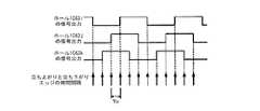
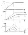
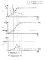
図5は、従来のソフトスタート制御について説明する図であり、図6は、負荷が小さい場合(軽負荷時)の本実施の形態によるソフトスタート制御について説明する図であり、図7は、負荷が大きい場合(重負荷時)の本実施の形態によるソフトスタート制御について説明する図である。各図において、(a)は、PWMデューティの変化を時間毎に表した図であり、(b)は、モータの回転数の変化を時間毎に表した図であり、(c)は、モータに流れる電流の変化を時間毎に表した図である。 FIG. 5 is a diagram for explaining the conventional soft start control, FIG. 6 is a diagram for explaining the soft start control according to the present embodiment when the load is small (light load), and FIG. It is a figure explaining the soft start control by this Embodiment when it is large (at the time of heavy load). In each figure, (a) is a diagram showing changes in PWM duty for each time, (b) is a diagram showing changes in the rotational speed of the motor for each time, and (c) is a motor. It is the figure which represented the change of the electric current which flows into every time.
ソフトスタート制御とは、モータの起動時に多大な起動電流が発生することを防止するためにPWMデューティを目標値まで徐々に増加させる制御である。起動電流の大きさは、モータの回転数に対するモータへの印加電圧の大きさに依存しているので、一般には、起動電流は、PWMデューティが目標値に達した時点で最大となる。本実施の形態では、PWMデューティの目標値が100%の場合を想定して説明するが、他の目標値の場合でも同様に考えることが可能である。また、目標値の設定方法も複数考えられ、例えば、トリガ部52が少しでも押し込まれれば目標値を100%に設定するように構成することも可能である。 The soft start control is a control for gradually increasing the PWM duty to a target value in order to prevent a large starting current from being generated when the motor is started. Since the magnitude of the starting current depends on the magnitude of the voltage applied to the motor with respect to the number of rotations of the motor, in general, the starting current becomes maximum when the PWM duty reaches the target value. In the present embodiment, the case where the target value of PWM duty is 100% will be described. However, the same can be considered for other target values. A plurality of target value setting methods are also conceivable. For example, if the
図5に示すように、従来のソフトスタート制御では、PWMデューティを一定の増加率で増加させるため、多大な起動電流が発生する虞の少ない小さな負荷の場合には、モータの起動に必要以上の時間がかかると同時に、トリガ操作に対するモータへの電力供給の追従性が悪くなってしまう。特に、トリガのオン・オフの繰り返しにより小ネジを締結するような場合には、ユーザにとって非常に使用感の悪いものとなってしまう。一方で、負荷が想定以上の大きさであった場合には、ソフトスタート制御を行っても多大な起動電流(過電流)が発生してしまい、温度上昇に伴うモータやインバータ回路等の熱損が生じる虞がある。 As shown in FIG. 5, in the conventional soft start control, the PWM duty is increased at a constant increase rate. Therefore, in the case of a small load that is unlikely to generate a large starting current, it is more than necessary for starting the motor. At the same time, followability of power supply to the motor with respect to the trigger operation is deteriorated. In particular, when the small screw is fastened by repeating the on / off of the trigger, the feeling of use is very bad for the user. On the other hand, if the load is larger than expected, a large start-up current (overcurrent) will occur even if soft start control is performed, resulting in heat loss of the motor, inverter circuit, etc. due to temperature rise. May occur.
そこで、本実施の形態によるソフトスタート制御では、負荷の大きさに応じてPWMデューティの増加率を変更する。具体的には、図6に示すように、PWMデューティの増加率Daでソフトスタート制御を開始し、PWMデューティが100%に達する前にモータ63の回転数が閾値Nthを超えた場合には、軽負荷であると判断して増加率をDaより大きいDbに変更する。本実施の形態では、従来の増加率Dcを0.5%/msecに想定した上で、増加率Daを0.3%/msecに、増加率Dbを1.2%/msecに、閾値Nthを4000rpmに設定している。これにより、PWMデューティを目標値まで増加させるための起動時間を短縮することができる。更に、トリガ部52のオン・オフの繰り返しにより小ネジを締結するような場合であっても、モータ63を停止状態から高速回転まで短時間で加速することができるので、トリガ部52の操作に対するモータ63への電力供給の追従性を大幅に改善することが可能となる。 Therefore, in the soft start control according to the present embodiment, the PWM duty increase rate is changed in accordance with the magnitude of the load. Specifically, as shown in FIG. 6, when the soft start control is started at the PWM duty increase rate Da, and the rotational speed of the
一方、PWMデューティが100%に達するまでにモータ63の回転数が閾値Nthを超えなかった場合には、重負荷であると判断して増加率を変更しない。これにより、低速回転中のモータ63に大きな電圧が印加されて多大な起動電流が発生することを防止することができる。特に、本実施の形態では、増加率Daは、従来のソフトスタート制御における増加率Dcよりも小さな値に設定されているため、図7に示すように、過電流領域に達するような多大な起動電流を発生させることなくソフトスタート制御を終了させることができ、これにより、温度上昇に伴うモータやインバータ回路等の熱損の発生を防止し、製品の信頼性を向上させることが可能となる。 On the other hand, if the rotational speed of the
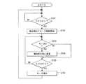
次に、図8のフローチャートを用いて、ソフトスタート制御時の制御回路部51の動作について説明する。本フローチャートは、ドライバドリル1の電源がオンされたことを契機に開始される。 Next, the operation of the
まず、トリガ部52がオンされたか否かを判別する(S101)。トリガ部52がオンされた場合には(S101:YES)、PWMデューティの増加率Daでモータ63の起動を開始させた後(S102)、モータ63の回転数Nが閾値Nthを超えたか否かを判別する(S103)。閾値Nthを超えていた場合には(S103:YES)、増加率をDbに変更した後(S104)、トリガ部52がオフされたか否かを判別する(S105)。一方、閾値Nthを超えてない場合には(S103:NO)、そのまま、S105に進み、トリガ部52がオフされたか否かを判別する。トリガ部52がオフされていなかった場合には(S105:NO)、S103に戻り、再び、モータの回転数Nが閾値Nthを超えたか否かを判別する。一方、トリガ部52がオフされていた場合には(S105:YES)、モータ63の起動を停止させた後(S106)、S101に戻り、再び、トリガ部52がオンされたか否かを判別する。 First, it is determined whether or not the
上記したように、本実施の形態によるドライバドリル1は、モータの起動時にモータへ印加する電圧の増加率を、モータ63の回転数(モータ63にかかる負荷の大きさ)に応じて変更するので、負荷の大きさに応じた適切なソフトスタート制御を行うことが可能となる。 As described above, the driver drill 1 according to the present embodiment changes the rate of increase of the voltage applied to the motor at the time of starting the motor according to the number of rotations of the motor 63 (the magnitude of the load applied to the motor 63). Thus, it is possible to perform appropriate soft start control according to the magnitude of the load.
次に、閾値Nth並びに増加率Da及びDbの決定方法について説明する。本実施の形態では、閾値Nth及び増加率Daは、想定される最大の重負荷作業を行うことによって決定され、増加率Dbは、想定される最小の軽負荷作業を行うことによって決定される。具体的には、増加率Daは、最大の重負荷作業時に起動電流が過電流領域を超えないような値に決定される。閾値Nthは、増加率Daが切り替わらないように、PWMデューティが100%まで増加した瞬間の回転数よりも大きい値に決定される。増加率Dbは、回転数が閾値Nthに達して増加率が増加率Daから切り替わった場合に起動電流が過電流領域を超えないような値に決定される。 Next, a method for determining the threshold value Nth and the increase rates Da and Db will be described. In the present embodiment, the threshold value Nth and the increase rate Da are determined by performing an assumed maximum heavy load operation, and the increase rate Db is determined by performing an assumed minimum light load operation. Specifically, the increase rate Da is determined to be a value such that the starting current does not exceed the overcurrent region during the maximum heavy load operation. The threshold value Nth is determined to be larger than the rotational speed at the moment when the PWM duty is increased to 100% so that the increase rate Da is not switched. The increase rate Db is determined to a value such that the starting current does not exceed the overcurrent region when the rotation speed reaches the threshold value Nth and the increase rate is switched from the increase rate Da.
なお、本発明による電動工具は、上述した実施の形態に限定されず、特許請求の範囲に記載された範囲で種々の変形や改良が可能である。 In addition, the electric tool by this invention is not limited to embodiment mentioned above, A various deformation | transformation and improvement are possible in the range described in the claim.
例えば、上記実施の形態では、閾値Nthを1つだけ設定していたが、2以上の閾値を設定し、PWMデューティの増加率を複数段階で変更してもよい。また、ソフトスタート制御中の所定時間経過後にモータ63の回転数が所定値まで上がらなかった場合には、想定以上の重負荷であると判断し、増加率を下げてもよい。これにより、製品の信頼性をより向上させることが可能となる。 For example, in the above embodiment, only one threshold value Nth is set, but two or more threshold values may be set and the PWM duty increase rate may be changed in a plurality of stages. In addition, when the rotation speed of the
また、上記実施の形態では、回転数を用いて負荷を判断したが、電流検出回路511によって検出されたモータ63に流れる電流を用いてもよい。 In the above embodiment, the load is determined using the rotation speed, but the current flowing through the
また、上記実施の形態では、本発明の電動工具としてドライバドリル1を用いた例を示したが、インパクトドライバ、ハンマドリル等の他の電動工具を用いてもよい。
であっても良い。Moreover, in the said embodiment, although the example using the driver drill 1 was shown as an electric tool of this invention, you may use other electric tools, such as an impact driver and a hammer drill.
It may be.
また、上記実施の形態では、本発明のモータとして、PWM制御により回転数が制御されるブラシレス直流モータ63を用いたが、サイリスタ位相制御によりトライアックの通電角が制御されるユニバーサルモータを用いてもよい。 In the above embodiment, the
また、上記実施の形態では、本発明の制御部による制御として、PWM制御を用いたが、PAM制御等を用いてもよい。 Moreover, in the said embodiment, although PWM control was used as control by the control part of this invention, you may use PAM control etc.
1 ドライバドリル
2 電池パック
51 制御回路部
52 トリガ部
61 吸気口
62 インバータ回路部
63 モータ
63i−k ホールIC
Q1-Q6 スイッチング素子
DESCRIPTION OF SYMBOLS 1
Q1-Q6 switching element
Claims (6)
Translated fromJapanese前記モータに電圧を印加する電圧印加部と、
前記電圧印加部から前記モータへの電圧印加の開始を指示するトリガと、
前記トリガからの指示に応じて、前記モータに印加される電圧が目標値に達するまで、所定の増加率で前記モータに前記電圧を印加するように前記電圧印加部を制御する制御部と、
を備えた電動工具であって、
前記モータにかかる負荷の大きさを検出する負荷検出部を更に備え、
前記制御部は、前記負荷の大きさに応じて前記所定の増加率を変更することを特徴とする電動工具。A motor,
A voltage application unit for applying a voltage to the motor;
A trigger for instructing the start of voltage application from the voltage application unit to the motor;
In response to an instruction from the trigger, a control unit that controls the voltage application unit to apply the voltage to the motor at a predetermined increase rate until the voltage applied to the motor reaches a target value;
An electric tool comprising
A load detection unit for detecting a load applied to the motor;
The said control part changes the said predetermined increase rate according to the magnitude | size of the said load, The electric tool characterized by the above-mentioned.
前記制御部は、前記モータへの電力の供給開始から所定時間経過後における前記回転数又は前記電流が所定の閾値に達した場合に前記所定の増加率を変更することを特徴とする請求項1に記載の電動工具。A rotation number / current detection unit for detecting a rotation number of the motor or a current flowing through the motor;
The control unit changes the predetermined increase rate when the rotation speed or the current after a predetermined time elapses after the start of supply of electric power to the motor reaches a predetermined threshold value. The electric tool as described in.
前記制御部は、PWM制御により前記スイッチを制御することを特徴とする請求項1に記載の電動工具。A switch for switching on / off power supply to the motor;
The electric power tool according to claim 1, wherein the control unit controls the switch by PWM control.
前記制御部は、サイリスタ位相制御により前記スイッチを制御することを特徴とする請求項1に記載の電動工具。A switch for switching on / off power supply to the motor;
The power tool according to claim 1, wherein the control unit controls the switch by thyristor phase control.
Priority Applications (3)
| Application Number | Priority Date | Filing Date | Title |
|---|---|---|---|
| JP2010115152AJP5534327B2 (en) | 2010-05-19 | 2010-05-19 | Electric tool |
| US13/109,860US8931576B2 (en) | 2010-05-19 | 2011-05-17 | Power tool for performing soft-start control appropriated for motor load |
| CN201110135415.6ACN102248522B (en) | 2010-05-19 | 2011-05-19 | Power tool |
Applications Claiming Priority (1)
| Application Number | Priority Date | Filing Date | Title |
|---|---|---|---|
| JP2010115152AJP5534327B2 (en) | 2010-05-19 | 2010-05-19 | Electric tool |
Publications (2)
| Publication Number | Publication Date |
|---|---|
| JP2011240441A JP2011240441A (en) | 2011-12-01 |
| JP5534327B2true JP5534327B2 (en) | 2014-06-25 |
Family
ID=44971510
Family Applications (1)
| Application Number | Title | Priority Date | Filing Date |
|---|---|---|---|
| JP2010115152AExpired - Fee RelatedJP5534327B2 (en) | 2010-05-19 | 2010-05-19 | Electric tool |
Country Status (3)
| Country | Link |
|---|---|
| US (1) | US8931576B2 (en) |
| JP (1) | JP5534327B2 (en) |
| CN (1) | CN102248522B (en) |
Families Citing this family (478)
| Publication number | Priority date | Publication date | Assignee | Title |
|---|---|---|---|---|
| US20070084897A1 (en) | 2003-05-20 | 2007-04-19 | Shelton Frederick E Iv | Articulating surgical stapling instrument incorporating a two-piece e-beam firing mechanism |
| US9060770B2 (en) | 2003-05-20 | 2015-06-23 | Ethicon Endo-Surgery, Inc. | Robotically-driven surgical instrument with E-beam driver |
| US11890012B2 (en) | 2004-07-28 | 2024-02-06 | Cilag Gmbh International | Staple cartridge comprising cartridge body and attached support |
| US11998198B2 (en) | 2004-07-28 | 2024-06-04 | Cilag Gmbh International | Surgical stapling instrument incorporating a two-piece E-beam firing mechanism |
| US9072535B2 (en) | 2011-05-27 | 2015-07-07 | Ethicon Endo-Surgery, Inc. | Surgical stapling instruments with rotatable staple deployment arrangements |
| US8215531B2 (en) | 2004-07-28 | 2012-07-10 | Ethicon Endo-Surgery, Inc. | Surgical stapling instrument having a medical substance dispenser |
| US10159482B2 (en) | 2005-08-31 | 2018-12-25 | Ethicon Llc | Fastener cartridge assembly comprising a fixed anvil and different staple heights |
| US7669746B2 (en) | 2005-08-31 | 2010-03-02 | Ethicon Endo-Surgery, Inc. | Staple cartridges for forming staples having differing formed staple heights |
| US7934630B2 (en) | 2005-08-31 | 2011-05-03 | Ethicon Endo-Surgery, Inc. | Staple cartridges for forming staples having differing formed staple heights |
| US11246590B2 (en) | 2005-08-31 | 2022-02-15 | Cilag Gmbh International | Staple cartridge including staple drivers having different unfired heights |
| US11484312B2 (en) | 2005-08-31 | 2022-11-01 | Cilag Gmbh International | Staple cartridge comprising a staple driver arrangement |
| US9237891B2 (en) | 2005-08-31 | 2016-01-19 | Ethicon Endo-Surgery, Inc. | Robotically-controlled surgical stapling devices that produce formed staples having different lengths |
| US20070106317A1 (en) | 2005-11-09 | 2007-05-10 | Shelton Frederick E Iv | Hydraulically and electrically actuated articulation joints for surgical instruments |
| US20120292367A1 (en) | 2006-01-31 | 2012-11-22 | Ethicon Endo-Surgery, Inc. | Robotically-controlled end effector |
| US11224427B2 (en) | 2006-01-31 | 2022-01-18 | Cilag Gmbh International | Surgical stapling system including a console and retraction assembly |
| US20110295295A1 (en) | 2006-01-31 | 2011-12-01 | Ethicon Endo-Surgery, Inc. | Robotically-controlled surgical instrument having recording capabilities |
| US7845537B2 (en) | 2006-01-31 | 2010-12-07 | Ethicon Endo-Surgery, Inc. | Surgical instrument having recording capabilities |
| US11793518B2 (en) | 2006-01-31 | 2023-10-24 | Cilag Gmbh International | Powered surgical instruments with firing system lockout arrangements |
| US8820603B2 (en) | 2006-01-31 | 2014-09-02 | Ethicon Endo-Surgery, Inc. | Accessing data stored in a memory of a surgical instrument |
| US20110024477A1 (en) | 2009-02-06 | 2011-02-03 | Hall Steven G | Driven Surgical Stapler Improvements |
| US11278279B2 (en) | 2006-01-31 | 2022-03-22 | Cilag Gmbh International | Surgical instrument assembly |
| US7753904B2 (en) | 2006-01-31 | 2010-07-13 | Ethicon Endo-Surgery, Inc. | Endoscopic surgical instrument with a handle that can articulate with respect to the shaft |
| US8186555B2 (en) | 2006-01-31 | 2012-05-29 | Ethicon Endo-Surgery, Inc. | Motor-driven surgical cutting and fastening instrument with mechanical closure system |
| US8708213B2 (en) | 2006-01-31 | 2014-04-29 | Ethicon Endo-Surgery, Inc. | Surgical instrument having a feedback system |
| US8992422B2 (en) | 2006-03-23 | 2015-03-31 | Ethicon Endo-Surgery, Inc. | Robotically-controlled endoscopic accessory channel |
| US8322455B2 (en) | 2006-06-27 | 2012-12-04 | Ethicon Endo-Surgery, Inc. | Manually driven surgical cutting and fastening instrument |
| US10568652B2 (en) | 2006-09-29 | 2020-02-25 | Ethicon Llc | Surgical staples having attached drivers of different heights and stapling instruments for deploying the same |
| US7506791B2 (en) | 2006-09-29 | 2009-03-24 | Ethicon Endo-Surgery, Inc. | Surgical stapling instrument with mechanical mechanism for limiting maximum tissue compression |
| US11980366B2 (en) | 2006-10-03 | 2024-05-14 | Cilag Gmbh International | Surgical instrument |
| US8632535B2 (en) | 2007-01-10 | 2014-01-21 | Ethicon Endo-Surgery, Inc. | Interlock and surgical instrument including same |
| US11291441B2 (en) | 2007-01-10 | 2022-04-05 | Cilag Gmbh International | Surgical instrument with wireless communication between control unit and remote sensor |
| US8684253B2 (en) | 2007-01-10 | 2014-04-01 | Ethicon Endo-Surgery, Inc. | Surgical instrument with wireless communication between a control unit of a robotic system and remote sensor |
| US8652120B2 (en) | 2007-01-10 | 2014-02-18 | Ethicon Endo-Surgery, Inc. | Surgical instrument with wireless communication between control unit and sensor transponders |
| US11039836B2 (en) | 2007-01-11 | 2021-06-22 | Cilag Gmbh International | Staple cartridge for use with a surgical stapling instrument |
| US20080169333A1 (en) | 2007-01-11 | 2008-07-17 | Shelton Frederick E | Surgical stapler end effector with tapered distal end |
| US7673782B2 (en) | 2007-03-15 | 2010-03-09 | Ethicon Endo-Surgery, Inc. | Surgical stapling instrument having a releasable buttress material |
| US8893946B2 (en) | 2007-03-28 | 2014-11-25 | Ethicon Endo-Surgery, Inc. | Laparoscopic tissue thickness and clamp load measuring devices |
| US11564682B2 (en) | 2007-06-04 | 2023-01-31 | Cilag Gmbh International | Surgical stapler device |
| US8931682B2 (en) | 2007-06-04 | 2015-01-13 | Ethicon Endo-Surgery, Inc. | Robotically-controlled shaft based rotary drive systems for surgical instruments |
| US7753245B2 (en) | 2007-06-22 | 2010-07-13 | Ethicon Endo-Surgery, Inc. | Surgical stapling instruments |
| US11849941B2 (en) | 2007-06-29 | 2023-12-26 | Cilag Gmbh International | Staple cartridge having staple cavities extending at a transverse angle relative to a longitudinal cartridge axis |
| US9179912B2 (en) | 2008-02-14 | 2015-11-10 | Ethicon Endo-Surgery, Inc. | Robotically-controlled motorized surgical cutting and fastening instrument |
| US8758391B2 (en) | 2008-02-14 | 2014-06-24 | Ethicon Endo-Surgery, Inc. | Interchangeable tools for surgical instruments |
| US8573465B2 (en) | 2008-02-14 | 2013-11-05 | Ethicon Endo-Surgery, Inc. | Robotically-controlled surgical end effector system with rotary actuated closure systems |
| US11986183B2 (en) | 2008-02-14 | 2024-05-21 | Cilag Gmbh International | Surgical cutting and fastening instrument comprising a plurality of sensors to measure an electrical parameter |
| US7819298B2 (en) | 2008-02-14 | 2010-10-26 | Ethicon Endo-Surgery, Inc. | Surgical stapling apparatus with control features operable with one hand |
| JP5410110B2 (en) | 2008-02-14 | 2014-02-05 | エシコン・エンド−サージェリィ・インコーポレイテッド | Surgical cutting / fixing instrument with RF electrode |
| US8636736B2 (en) | 2008-02-14 | 2014-01-28 | Ethicon Endo-Surgery, Inc. | Motorized surgical cutting and fastening instrument |
| US7866527B2 (en) | 2008-02-14 | 2011-01-11 | Ethicon Endo-Surgery, Inc. | Surgical stapling apparatus with interlockable firing system |
| US9585657B2 (en) | 2008-02-15 | 2017-03-07 | Ethicon Endo-Surgery, Llc | Actuator for releasing a layer of material from a surgical end effector |
| US11272927B2 (en) | 2008-02-15 | 2022-03-15 | Cilag Gmbh International | Layer arrangements for surgical staple cartridges |
| US9386983B2 (en) | 2008-09-23 | 2016-07-12 | Ethicon Endo-Surgery, Llc | Robotically-controlled motorized surgical instrument |
| US9005230B2 (en) | 2008-09-23 | 2015-04-14 | Ethicon Endo-Surgery, Inc. | Motorized surgical instrument |
| US8210411B2 (en) | 2008-09-23 | 2012-07-03 | Ethicon Endo-Surgery, Inc. | Motor-driven surgical cutting instrument |
| US11648005B2 (en) | 2008-09-23 | 2023-05-16 | Cilag Gmbh International | Robotically-controlled motorized surgical instrument with an end effector |
| US8608045B2 (en) | 2008-10-10 | 2013-12-17 | Ethicon Endo-Sugery, Inc. | Powered surgical cutting and stapling apparatus with manually retractable firing system |
| US8686675B2 (en)* | 2009-01-19 | 2014-04-01 | Hitachi Koki Co., Ltd. | Power tool |
| US8517239B2 (en) | 2009-02-05 | 2013-08-27 | Ethicon Endo-Surgery, Inc. | Surgical stapling instrument comprising a magnetic element driver |
| US8444036B2 (en) | 2009-02-06 | 2013-05-21 | Ethicon Endo-Surgery, Inc. | Motor driven surgical fastener device with mechanisms for adjusting a tissue gap within the end effector |
| RU2525225C2 (en) | 2009-02-06 | 2014-08-10 | Этикон Эндо-Серджери, Инк. | Improvement of drive surgical suturing instrument |
| US8220688B2 (en) | 2009-12-24 | 2012-07-17 | Ethicon Endo-Surgery, Inc. | Motor-driven surgical cutting instrument with electric actuator directional control assembly |
| US8851354B2 (en) | 2009-12-24 | 2014-10-07 | Ethicon Endo-Surgery, Inc. | Surgical cutting instrument that analyzes tissue thickness |
| US9950417B2 (en)* | 2010-03-31 | 2018-04-24 | Hitachi Koki Co., Ltd. | Power tool |
| US8783543B2 (en) | 2010-07-30 | 2014-07-22 | Ethicon Endo-Surgery, Inc. | Tissue acquisition arrangements and methods for surgical stapling devices |
| US11298125B2 (en) | 2010-09-30 | 2022-04-12 | Cilag Gmbh International | Tissue stapler having a thickness compensator |
| US10945731B2 (en) | 2010-09-30 | 2021-03-16 | Ethicon Llc | Tissue thickness compensator comprising controlled release and expansion |
| US9016542B2 (en) | 2010-09-30 | 2015-04-28 | Ethicon Endo-Surgery, Inc. | Staple cartridge comprising compressible distortion resistant components |
| US9364233B2 (en) | 2010-09-30 | 2016-06-14 | Ethicon Endo-Surgery, Llc | Tissue thickness compensators for circular surgical staplers |
| US11925354B2 (en) | 2010-09-30 | 2024-03-12 | Cilag Gmbh International | Staple cartridge comprising staples positioned within a compressible portion thereof |
| US12213666B2 (en) | 2010-09-30 | 2025-02-04 | Cilag Gmbh International | Tissue thickness compensator comprising layers |
| US9788834B2 (en) | 2010-09-30 | 2017-10-17 | Ethicon Llc | Layer comprising deployable attachment members |
| US9629814B2 (en) | 2010-09-30 | 2017-04-25 | Ethicon Endo-Surgery, Llc | Tissue thickness compensator configured to redistribute compressive forces |
| US9351730B2 (en) | 2011-04-29 | 2016-05-31 | Ethicon Endo-Surgery, Llc | Tissue thickness compensator comprising channels |
| US11812965B2 (en) | 2010-09-30 | 2023-11-14 | Cilag Gmbh International | Layer of material for a surgical end effector |
| US9386988B2 (en) | 2010-09-30 | 2016-07-12 | Ethicon End-Surgery, LLC | Retainer assembly including a tissue thickness compensator |
| US9232941B2 (en) | 2010-09-30 | 2016-01-12 | Ethicon Endo-Surgery, Inc. | Tissue thickness compensator comprising a reservoir |
| US8695866B2 (en) | 2010-10-01 | 2014-04-15 | Ethicon Endo-Surgery, Inc. | Surgical instrument having a power control circuit |
| AU2012250197B2 (en) | 2011-04-29 | 2017-08-10 | Ethicon Endo-Surgery, Inc. | Staple cartridge comprising staples positioned within a compressible portion thereof |
| US11207064B2 (en) | 2011-05-27 | 2021-12-28 | Cilag Gmbh International | Automated end effector component reloading system for use with a robotic system |
| JP5814151B2 (en) | 2012-02-09 | 2015-11-17 | 株式会社マキタ | Electric tool |
| US9044230B2 (en) | 2012-02-13 | 2015-06-02 | Ethicon Endo-Surgery, Inc. | Surgical cutting and fastening instrument with apparatus for determining cartridge and firing motion status |
| CN103312139B (en) | 2012-03-09 | 2016-05-11 | 台达电子工业股份有限公司 | A starting device and control method for a grid-connected inverter |
| JP5891410B2 (en)* | 2012-03-13 | 2016-03-23 | パナソニックIpマネジメント株式会社 | Electric tool |
| JP2013202702A (en)* | 2012-03-27 | 2013-10-07 | Hitachi Koki Co Ltd | Power tool |
| MX358135B (en) | 2012-03-28 | 2018-08-06 | Ethicon Endo Surgery Inc | Tissue thickness compensator comprising a plurality of layers. |
| BR112014024098B1 (en) | 2012-03-28 | 2021-05-25 | Ethicon Endo-Surgery, Inc. | staple cartridge |
| JP6224070B2 (en) | 2012-03-28 | 2017-11-01 | エシコン・エンド−サージェリィ・インコーポレイテッドEthicon Endo−Surgery,Inc. | Retainer assembly including tissue thickness compensator |
| JP5824419B2 (en)* | 2012-06-05 | 2015-11-25 | 株式会社マキタ | Electric tool |
| US9101358B2 (en) | 2012-06-15 | 2015-08-11 | Ethicon Endo-Surgery, Inc. | Articulatable surgical instrument comprising a firing drive |
| US20140001231A1 (en) | 2012-06-28 | 2014-01-02 | Ethicon Endo-Surgery, Inc. | Firing system lockout arrangements for surgical instruments |
| JP6290201B2 (en) | 2012-06-28 | 2018-03-07 | エシコン・エンド−サージェリィ・インコーポレイテッドEthicon Endo−Surgery,Inc. | Lockout for empty clip cartridge |
| BR112014032776B1 (en) | 2012-06-28 | 2021-09-08 | Ethicon Endo-Surgery, Inc | SURGICAL INSTRUMENT SYSTEM AND SURGICAL KIT FOR USE WITH A SURGICAL INSTRUMENT SYSTEM |
| US9289256B2 (en) | 2012-06-28 | 2016-03-22 | Ethicon Endo-Surgery, Llc | Surgical end effectors having angled tissue-contacting surfaces |
| US20140005718A1 (en) | 2012-06-28 | 2014-01-02 | Ethicon Endo-Surgery, Inc. | Multi-functional powered surgical device with external dissection features |
| US11278284B2 (en) | 2012-06-28 | 2022-03-22 | Cilag Gmbh International | Rotary drive arrangements for surgical instruments |
| US9408606B2 (en) | 2012-06-28 | 2016-08-09 | Ethicon Endo-Surgery, Llc | Robotically powered surgical device with manually-actuatable reversing system |
| US9282974B2 (en) | 2012-06-28 | 2016-03-15 | Ethicon Endo-Surgery, Llc | Empty clip cartridge lockout |
| US12383267B2 (en) | 2012-06-28 | 2025-08-12 | Cilag Gmbh International | Robotically powered surgical device with manually-actuatable reversing system |
| DE102012214975A1 (en)* | 2012-08-23 | 2014-02-27 | Hilti Aktiengesellschaft | Method and device for controlling an electric motor of a hand tool machine |
| JP5958817B2 (en)* | 2012-09-07 | 2016-08-02 | パナソニックIpマネジメント株式会社 | Electric tool |
| JP2014091167A (en)* | 2012-10-31 | 2014-05-19 | Hitachi Koki Co Ltd | Electric power tool |
| EP2926952A4 (en)* | 2012-11-29 | 2016-08-03 | Hitachi Koki Kk | PERCUSSION TOOL |
| JP6085488B2 (en)* | 2013-01-28 | 2017-02-22 | 株式会社マキタ | Electric tool |
| BR112015021082B1 (en) | 2013-03-01 | 2022-05-10 | Ethicon Endo-Surgery, Inc | surgical instrument |
| RU2672520C2 (en) | 2013-03-01 | 2018-11-15 | Этикон Эндо-Серджери, Инк. | Hingedly turnable surgical instruments with conducting ways for signal transfer |
| US9808244B2 (en) | 2013-03-14 | 2017-11-07 | Ethicon Llc | Sensor arrangements for absolute positioning system for surgical instruments |
| US9629629B2 (en) | 2013-03-14 | 2017-04-25 | Ethicon Endo-Surgey, LLC | Control systems for surgical instruments |
| BR112015026109B1 (en) | 2013-04-16 | 2022-02-22 | Ethicon Endo-Surgery, Inc | surgical instrument |
| US9826976B2 (en) | 2013-04-16 | 2017-11-28 | Ethicon Llc | Motor driven surgical instruments with lockable dual drive shafts |
| JP2015009316A (en)* | 2013-06-28 | 2015-01-19 | 株式会社マキタ | Electric tool |
| JP6154242B2 (en)* | 2013-08-07 | 2017-06-28 | 株式会社マキタ | Electric machinery / equipment |
| JP6090576B2 (en)* | 2013-08-19 | 2017-03-08 | 日立工機株式会社 | Electric tool |
| MX369362B (en) | 2013-08-23 | 2019-11-06 | Ethicon Endo Surgery Llc | Firing member retraction devices for powered surgical instruments. |
| US9775609B2 (en) | 2013-08-23 | 2017-10-03 | Ethicon Llc | Tamper proof circuit for surgical instrument battery pack |
| JP6187815B2 (en) | 2013-09-25 | 2017-08-30 | パナソニックIpマネジメント株式会社 | Electric tool |
| JP6090581B2 (en)* | 2013-09-28 | 2017-03-08 | 日立工機株式会社 | Electric tool |
| US9724795B2 (en)* | 2013-11-07 | 2017-08-08 | Apex Brands, Inc. | Tooling system with visual identification of attached component |
| JP2015123546A (en)* | 2013-12-26 | 2015-07-06 | 日立工機株式会社 | Electric tool |
| US9962161B2 (en) | 2014-02-12 | 2018-05-08 | Ethicon Llc | Deliverable surgical instrument |
| JP6462004B2 (en) | 2014-02-24 | 2019-01-30 | エシコン エルエルシー | Fastening system with launcher lockout |
| US10004497B2 (en) | 2014-03-26 | 2018-06-26 | Ethicon Llc | Interface systems for use with surgical instruments |
| BR112016021943B1 (en) | 2014-03-26 | 2022-06-14 | Ethicon Endo-Surgery, Llc | SURGICAL INSTRUMENT FOR USE BY AN OPERATOR IN A SURGICAL PROCEDURE |
| US20150272580A1 (en) | 2014-03-26 | 2015-10-01 | Ethicon Endo-Surgery, Inc. | Verification of number of battery exchanges/procedure count |
| US12232723B2 (en) | 2014-03-26 | 2025-02-25 | Cilag Gmbh International | Systems and methods for controlling a segmented circuit |
| US10013049B2 (en) | 2014-03-26 | 2018-07-03 | Ethicon Llc | Power management through sleep options of segmented circuit and wake up control |
| JP6128037B2 (en)* | 2014-03-28 | 2017-05-17 | 日立工機株式会社 | Electric tool |
| CN106456159B (en) | 2014-04-16 | 2019-03-08 | 伊西康内外科有限责任公司 | Fastener Cartridge Assembly and Nail Retainer Cover Arrangement |
| US10327764B2 (en) | 2014-09-26 | 2019-06-25 | Ethicon Llc | Method for creating a flexible staple line |
| BR112016023825B1 (en) | 2014-04-16 | 2022-08-02 | Ethicon Endo-Surgery, Llc | STAPLE CARTRIDGE FOR USE WITH A SURGICAL STAPLER AND STAPLE CARTRIDGE FOR USE WITH A SURGICAL INSTRUMENT |
| US20150297225A1 (en) | 2014-04-16 | 2015-10-22 | Ethicon Endo-Surgery, Inc. | Fastener cartridges including extensions having different configurations |
| US10470768B2 (en) | 2014-04-16 | 2019-11-12 | Ethicon Llc | Fastener cartridge including a layer attached thereto |
| CN106456176B (en) | 2014-04-16 | 2019-06-28 | 伊西康内外科有限责任公司 | Fastener Cartridge Including Extensions With Different Configurations |
| EP2947765B1 (en) | 2014-05-20 | 2020-08-26 | Black & Decker Inc. | Electronic braking for a universal motor in a power tool |
| US11311294B2 (en) | 2014-09-05 | 2022-04-26 | Cilag Gmbh International | Powered medical device including measurement of closure state of jaws |
| US10135242B2 (en) | 2014-09-05 | 2018-11-20 | Ethicon Llc | Smart cartridge wake up operation and data retention |
| BR112017004361B1 (en) | 2014-09-05 | 2023-04-11 | Ethicon Llc | ELECTRONIC SYSTEM FOR A SURGICAL INSTRUMENT |
| US10105142B2 (en) | 2014-09-18 | 2018-10-23 | Ethicon Llc | Surgical stapler with plurality of cutting elements |
| US11523821B2 (en) | 2014-09-26 | 2022-12-13 | Cilag Gmbh International | Method for creating a flexible staple line |
| CN107427300B (en) | 2014-09-26 | 2020-12-04 | 伊西康有限责任公司 | Surgical suture buttresses and auxiliary materials |
| US10076325B2 (en) | 2014-10-13 | 2018-09-18 | Ethicon Llc | Surgical stapling apparatus comprising a tissue stop |
| US9924944B2 (en) | 2014-10-16 | 2018-03-27 | Ethicon Llc | Staple cartridge comprising an adjunct material |
| JP6690115B2 (en)* | 2014-10-28 | 2020-04-28 | 工機ホールディングス株式会社 | Electric tool |
| US11141153B2 (en) | 2014-10-29 | 2021-10-12 | Cilag Gmbh International | Staple cartridges comprising driver arrangements |
| US10517594B2 (en) | 2014-10-29 | 2019-12-31 | Ethicon Llc | Cartridge assemblies for surgical staplers |
| US9844376B2 (en) | 2014-11-06 | 2017-12-19 | Ethicon Llc | Staple cartridge comprising a releasable adjunct material |
| JP6414603B2 (en)* | 2014-11-28 | 2018-10-31 | 工機ホールディングス株式会社 | Electric tool |
| US10736636B2 (en) | 2014-12-10 | 2020-08-11 | Ethicon Llc | Articulatable surgical instrument system |
| US10085748B2 (en) | 2014-12-18 | 2018-10-02 | Ethicon Llc | Locking arrangements for detachable shaft assemblies with articulatable surgical end effectors |
| US10188385B2 (en) | 2014-12-18 | 2019-01-29 | Ethicon Llc | Surgical instrument system comprising lockable systems |
| MX389118B (en) | 2014-12-18 | 2025-03-20 | Ethicon Llc | SURGICAL INSTRUMENT WITH AN ANVIL THAT CAN BE SELECTIVELY MOVED ON A DISCRETE, NON-MOBILE AXIS RELATIVE TO A STAPLE CARTRIDGE. |
| US9943309B2 (en) | 2014-12-18 | 2018-04-17 | Ethicon Llc | Surgical instruments with articulatable end effectors and movable firing beam support arrangements |
| US9844375B2 (en) | 2014-12-18 | 2017-12-19 | Ethicon Llc | Drive arrangements for articulatable surgical instruments |
| EP3235119B1 (en) | 2014-12-18 | 2021-10-13 | Black & Decker Inc. | Control scheme to increase power output of a power tool using conduction band and advance angle |
| JP6460354B2 (en)* | 2014-12-18 | 2019-01-30 | 工機ホールディングス株式会社 | Electric tool |
| US9844374B2 (en) | 2014-12-18 | 2017-12-19 | Ethicon Llc | Surgical instrument systems comprising an articulatable end effector and means for adjusting the firing stroke of a firing member |
| US9987000B2 (en) | 2014-12-18 | 2018-06-05 | Ethicon Llc | Surgical instrument assembly comprising a flexible articulation system |
| US10180463B2 (en) | 2015-02-27 | 2019-01-15 | Ethicon Llc | Surgical apparatus configured to assess whether a performance parameter of the surgical apparatus is within an acceptable performance band |
| US10159483B2 (en) | 2015-02-27 | 2018-12-25 | Ethicon Llc | Surgical apparatus configured to track an end-of-life parameter |
| US11154301B2 (en) | 2015-02-27 | 2021-10-26 | Cilag Gmbh International | Modular stapling assembly |
| US10548504B2 (en) | 2015-03-06 | 2020-02-04 | Ethicon Llc | Overlaid multi sensor radio frequency (RF) electrode system to measure tissue compression |
| JP2020121162A (en) | 2015-03-06 | 2020-08-13 | エシコン エルエルシーEthicon LLC | Time dependent evaluation of sensor data to determine stability element, creep element and viscoelastic element of measurement |
| US9901342B2 (en) | 2015-03-06 | 2018-02-27 | Ethicon Endo-Surgery, Llc | Signal and power communication system positioned on a rotatable shaft |
| US9993248B2 (en) | 2015-03-06 | 2018-06-12 | Ethicon Endo-Surgery, Llc | Smart sensors with local signal processing |
| US10617412B2 (en) | 2015-03-06 | 2020-04-14 | Ethicon Llc | System for detecting the mis-insertion of a staple cartridge into a surgical stapler |
| US10245033B2 (en) | 2015-03-06 | 2019-04-02 | Ethicon Llc | Surgical instrument comprising a lockable battery housing |
| US10687806B2 (en) | 2015-03-06 | 2020-06-23 | Ethicon Llc | Adaptive tissue compression techniques to adjust closure rates for multiple tissue types |
| US9808246B2 (en) | 2015-03-06 | 2017-11-07 | Ethicon Endo-Surgery, Llc | Method of operating a powered surgical instrument |
| US9924961B2 (en) | 2015-03-06 | 2018-03-27 | Ethicon Endo-Surgery, Llc | Interactive feedback system for powered surgical instruments |
| US10441279B2 (en)* | 2015-03-06 | 2019-10-15 | Ethicon Llc | Multiple level thresholds to modify operation of powered surgical instruments |
| US10433844B2 (en) | 2015-03-31 | 2019-10-08 | Ethicon Llc | Surgical instrument with selectively disengageable threaded drive systems |
| US11260517B2 (en) | 2015-06-05 | 2022-03-01 | Ingersoll-Rand Industrial U.S., Inc. | Power tool housings |
| WO2016196918A1 (en) | 2015-06-05 | 2016-12-08 | Ingersoll-Rand Company | Power tool user interfaces |
| WO2016196984A1 (en)* | 2015-06-05 | 2016-12-08 | Ingersoll-Rand Company | Power tools with user-selectable operational modes |
| WO2016196979A1 (en) | 2015-06-05 | 2016-12-08 | Ingersoll-Rand Company | Impact tools with ring gear alignment features |
| US10835249B2 (en) | 2015-08-17 | 2020-11-17 | Ethicon Llc | Implantable layers for a surgical instrument |
| US10238386B2 (en) | 2015-09-23 | 2019-03-26 | Ethicon Llc | Surgical stapler having motor control based on an electrical parameter related to a motor current |
| US10327769B2 (en) | 2015-09-23 | 2019-06-25 | Ethicon Llc | Surgical stapler having motor control based on a drive system component |
| US10105139B2 (en) | 2015-09-23 | 2018-10-23 | Ethicon Llc | Surgical stapler having downstream current-based motor control |
| US10363036B2 (en) | 2015-09-23 | 2019-07-30 | Ethicon Llc | Surgical stapler having force-based motor control |
| US10299878B2 (en) | 2015-09-25 | 2019-05-28 | Ethicon Llc | Implantable adjunct systems for determining adjunct skew |
| US10980539B2 (en) | 2015-09-30 | 2021-04-20 | Ethicon Llc | Implantable adjunct comprising bonded layers |
| JP6513006B2 (en)* | 2015-09-30 | 2019-05-15 | 株式会社マキタ | Motor control device |
| US10433846B2 (en) | 2015-09-30 | 2019-10-08 | Ethicon Llc | Compressible adjunct with crossing spacer fibers |
| US10478188B2 (en) | 2015-09-30 | 2019-11-19 | Ethicon Llc | Implantable layer comprising a constricted configuration |
| US11890015B2 (en) | 2015-09-30 | 2024-02-06 | Cilag Gmbh International | Compressible adjunct with crossing spacer fibers |
| EP3370924B1 (en) | 2015-11-02 | 2021-05-05 | Black & Decker Inc. | Reducing noise and lowering harmonics in power tools using conduction band control schemes |
| DE102015226087A1 (en)* | 2015-12-18 | 2017-06-22 | Robert Bosch Gmbh | Hand tool with adjustable direction of rotation |
| US10368865B2 (en) | 2015-12-30 | 2019-08-06 | Ethicon Llc | Mechanisms for compensating for drivetrain failure in powered surgical instruments |
| US10265068B2 (en) | 2015-12-30 | 2019-04-23 | Ethicon Llc | Surgical instruments with separable motors and motor control circuits |
| US10292704B2 (en) | 2015-12-30 | 2019-05-21 | Ethicon Llc | Mechanisms for compensating for battery pack failure in powered surgical instruments |
| CN108778651B (en) | 2016-02-03 | 2021-06-18 | 米沃奇电动工具公司 | System and method for configuring a reciprocating saw |
| BR112018016098B1 (en) | 2016-02-09 | 2023-02-23 | Ethicon Llc | SURGICAL INSTRUMENT |
| US11213293B2 (en) | 2016-02-09 | 2022-01-04 | Cilag Gmbh International | Articulatable surgical instruments with single articulation link arrangements |
| US10413291B2 (en) | 2016-02-09 | 2019-09-17 | Ethicon Llc | Surgical instrument articulation mechanism with slotted secondary constraint |
| US10448948B2 (en) | 2016-02-12 | 2019-10-22 | Ethicon Llc | Mechanisms for compensating for drivetrain failure in powered surgical instruments |
| US10258331B2 (en) | 2016-02-12 | 2019-04-16 | Ethicon Llc | Mechanisms for compensating for drivetrain failure in powered surgical instruments |
| EP3292959B1 (en) | 2016-02-12 | 2021-06-16 | Black & Decker Inc. | Electronic braking for a power tool having a brushless motor |
| US11224426B2 (en) | 2016-02-12 | 2022-01-18 | Cilag Gmbh International | Mechanisms for compensating for drivetrain failure in powered surgical instruments |
| US10617413B2 (en) | 2016-04-01 | 2020-04-14 | Ethicon Llc | Closure system arrangements for surgical cutting and stapling devices with separate and distinct firing shafts |
| US10413297B2 (en) | 2016-04-01 | 2019-09-17 | Ethicon Llc | Surgical stapling system configured to apply annular rows of staples having different heights |
| DE102016106557A1 (en) | 2016-04-11 | 2017-10-12 | Festool Gmbh | Hand machine tool with a drive motor |
| US10492783B2 (en) | 2016-04-15 | 2019-12-03 | Ethicon, Llc | Surgical instrument with improved stop/start control during a firing motion |
| US10357247B2 (en) | 2016-04-15 | 2019-07-23 | Ethicon Llc | Surgical instrument with multiple program responses during a firing motion |
| US10335145B2 (en) | 2016-04-15 | 2019-07-02 | Ethicon Llc | Modular surgical instrument with configurable operating mode |
| US11179150B2 (en) | 2016-04-15 | 2021-11-23 | Cilag Gmbh International | Systems and methods for controlling a surgical stapling and cutting instrument |
| US10405859B2 (en) | 2016-04-15 | 2019-09-10 | Ethicon Llc | Surgical instrument with adjustable stop/start control during a firing motion |
| US10456137B2 (en) | 2016-04-15 | 2019-10-29 | Ethicon Llc | Staple formation detection mechanisms |
| US10828028B2 (en) | 2016-04-15 | 2020-11-10 | Ethicon Llc | Surgical instrument with multiple program responses during a firing motion |
| US11607239B2 (en) | 2016-04-15 | 2023-03-21 | Cilag Gmbh International | Systems and methods for controlling a surgical stapling and cutting instrument |
| US10426467B2 (en) | 2016-04-15 | 2019-10-01 | Ethicon Llc | Surgical instrument with detection sensors |
| US10363037B2 (en) | 2016-04-18 | 2019-07-30 | Ethicon Llc | Surgical instrument system comprising a magnetic lockout |
| US11317917B2 (en) | 2016-04-18 | 2022-05-03 | Cilag Gmbh International | Surgical stapling system comprising a lockable firing assembly |
| US20170296173A1 (en) | 2016-04-18 | 2017-10-19 | Ethicon Endo-Surgery, Llc | Method for operating a surgical instrument |
| US10680494B2 (en)* | 2016-06-24 | 2020-06-09 | Black & Decker Inc. | Control scheme for power tool having a brushless motor |
| US10500000B2 (en) | 2016-08-16 | 2019-12-10 | Ethicon Llc | Surgical tool with manual control of end effector jaws |
| JP6752092B2 (en)* | 2016-09-13 | 2020-09-09 | 株式会社ミツトヨ | Roundness measuring machine |
| US10898186B2 (en) | 2016-12-21 | 2021-01-26 | Ethicon Llc | Staple forming pocket arrangements comprising primary sidewalls and pocket sidewalls |
| MX2019007295A (en) | 2016-12-21 | 2019-10-15 | Ethicon Llc | Surgical instrument system comprising an end effector lockout and a firing assembly lockout. |
| US10980536B2 (en) | 2016-12-21 | 2021-04-20 | Ethicon Llc | No-cartridge and spent cartridge lockout arrangements for surgical staplers |
| US10758229B2 (en) | 2016-12-21 | 2020-09-01 | Ethicon Llc | Surgical instrument comprising improved jaw control |
| JP2020501815A (en) | 2016-12-21 | 2020-01-23 | エシコン エルエルシーEthicon LLC | Surgical stapling system |
| US10568625B2 (en) | 2016-12-21 | 2020-02-25 | Ethicon Llc | Staple cartridges and arrangements of staples and staple cavities therein |
| US10485543B2 (en) | 2016-12-21 | 2019-11-26 | Ethicon Llc | Anvil having a knife slot width |
| US10582928B2 (en) | 2016-12-21 | 2020-03-10 | Ethicon Llc | Articulation lock arrangements for locking an end effector in an articulated position in response to actuation of a jaw closure system |
| US10542982B2 (en) | 2016-12-21 | 2020-01-28 | Ethicon Llc | Shaft assembly comprising first and second articulation lockouts |
| US10973516B2 (en) | 2016-12-21 | 2021-04-13 | Ethicon Llc | Surgical end effectors and adaptable firing members therefor |
| US10426471B2 (en) | 2016-12-21 | 2019-10-01 | Ethicon Llc | Surgical instrument with multiple failure response modes |
| CN110087565A (en) | 2016-12-21 | 2019-08-02 | 爱惜康有限责任公司 | Surgical stapling system |
| US20180168625A1 (en) | 2016-12-21 | 2018-06-21 | Ethicon Endo-Surgery, Llc | Surgical stapling instruments with smart staple cartridges |
| JP7010957B2 (en) | 2016-12-21 | 2022-01-26 | エシコン エルエルシー | Shaft assembly with lockout |
| US20180168615A1 (en) | 2016-12-21 | 2018-06-21 | Ethicon Endo-Surgery, Llc | Method of deforming staples from two different types of staple cartridges with the same surgical stapling instrument |
| US11134942B2 (en) | 2016-12-21 | 2021-10-05 | Cilag Gmbh International | Surgical stapling instruments and staple-forming anvils |
| US11419606B2 (en) | 2016-12-21 | 2022-08-23 | Cilag Gmbh International | Shaft assembly comprising a clutch configured to adapt the output of a rotary firing member to two different systems |
| US10813638B2 (en) | 2016-12-21 | 2020-10-27 | Ethicon Llc | Surgical end effectors with expandable tissue stop arrangements |
| US11090048B2 (en) | 2016-12-21 | 2021-08-17 | Cilag Gmbh International | Method for resetting a fuse of a surgical instrument shaft |
| JP7010956B2 (en) | 2016-12-21 | 2022-01-26 | エシコン エルエルシー | How to staple tissue |
| JP6983893B2 (en) | 2016-12-21 | 2021-12-17 | エシコン エルエルシーEthicon LLC | Lockout configuration for surgical end effectors and replaceable tool assemblies |
| US10695055B2 (en) | 2016-12-21 | 2020-06-30 | Ethicon Llc | Firing assembly comprising a lockout |
| CN108613324A (en)* | 2017-01-25 | 2018-10-02 | 珠海格力电器股份有限公司 | Motor load matching state detection system and method and air conditioner |
| EP3612353B1 (en)* | 2017-04-19 | 2022-06-08 | Atlas Copco Industrial Technique AB | Electric pulse tool |
| USD879809S1 (en) | 2017-06-20 | 2020-03-31 | Ethicon Llc | Display panel with changeable graphical user interface |
| USD879808S1 (en) | 2017-06-20 | 2020-03-31 | Ethicon Llc | Display panel with graphical user interface |
| US10888321B2 (en) | 2017-06-20 | 2021-01-12 | Ethicon Llc | Systems and methods for controlling velocity of a displacement member of a surgical stapling and cutting instrument |
| US10390841B2 (en) | 2017-06-20 | 2019-08-27 | Ethicon Llc | Control of motor velocity of a surgical stapling and cutting instrument based on angle of articulation |
| US11090046B2 (en) | 2017-06-20 | 2021-08-17 | Cilag Gmbh International | Systems and methods for controlling displacement member motion of a surgical stapling and cutting instrument |
| US10881396B2 (en) | 2017-06-20 | 2021-01-05 | Ethicon Llc | Surgical instrument with variable duration trigger arrangement |
| US10646220B2 (en) | 2017-06-20 | 2020-05-12 | Ethicon Llc | Systems and methods for controlling displacement member velocity for a surgical instrument |
| US10327767B2 (en) | 2017-06-20 | 2019-06-25 | Ethicon Llc | Control of motor velocity of a surgical stapling and cutting instrument based on angle of articulation |
| US11653914B2 (en) | 2017-06-20 | 2023-05-23 | Cilag Gmbh International | Systems and methods for controlling motor velocity of a surgical stapling and cutting instrument according to articulation angle of end effector |
| US11382638B2 (en) | 2017-06-20 | 2022-07-12 | Cilag Gmbh International | Closed loop feedback control of motor velocity of a surgical stapling and cutting instrument based on measured time over a specified displacement distance |
| US11517325B2 (en) | 2017-06-20 | 2022-12-06 | Cilag Gmbh International | Closed loop feedback control of motor velocity of a surgical stapling and cutting instrument based on measured displacement distance traveled over a specified time interval |
| US11071554B2 (en) | 2017-06-20 | 2021-07-27 | Cilag Gmbh International | Closed loop feedback control of motor velocity of a surgical stapling and cutting instrument based on magnitude of velocity error measurements |
| US10813639B2 (en) | 2017-06-20 | 2020-10-27 | Ethicon Llc | Closed loop feedback control of motor velocity of a surgical stapling and cutting instrument based on system conditions |
| USD890784S1 (en) | 2017-06-20 | 2020-07-21 | Ethicon Llc | Display panel with changeable graphical user interface |
| US10779820B2 (en) | 2017-06-20 | 2020-09-22 | Ethicon Llc | Systems and methods for controlling motor speed according to user input for a surgical instrument |
| US10881399B2 (en) | 2017-06-20 | 2021-01-05 | Ethicon Llc | Techniques for adaptive control of motor velocity of a surgical stapling and cutting instrument |
| US10368864B2 (en) | 2017-06-20 | 2019-08-06 | Ethicon Llc | Systems and methods for controlling displaying motor velocity for a surgical instrument |
| US10624633B2 (en) | 2017-06-20 | 2020-04-21 | Ethicon Llc | Systems and methods for controlling motor velocity of a surgical stapling and cutting instrument |
| US10307170B2 (en) | 2017-06-20 | 2019-06-04 | Ethicon Llc | Method for closed loop control of motor velocity of a surgical stapling and cutting instrument |
| US10980537B2 (en) | 2017-06-20 | 2021-04-20 | Ethicon Llc | Closed loop feedback control of motor velocity of a surgical stapling and cutting instrument based on measured time over a specified number of shaft rotations |
| US10856869B2 (en) | 2017-06-27 | 2020-12-08 | Ethicon Llc | Surgical anvil arrangements |
| US11090049B2 (en) | 2017-06-27 | 2021-08-17 | Cilag Gmbh International | Staple forming pocket arrangements |
| US11324503B2 (en) | 2017-06-27 | 2022-05-10 | Cilag Gmbh International | Surgical firing member arrangements |
| US11266405B2 (en) | 2017-06-27 | 2022-03-08 | Cilag Gmbh International | Surgical anvil manufacturing methods |
| US10993716B2 (en) | 2017-06-27 | 2021-05-04 | Ethicon Llc | Surgical anvil arrangements |
| US10772629B2 (en) | 2017-06-27 | 2020-09-15 | Ethicon Llc | Surgical anvil arrangements |
| US11564686B2 (en) | 2017-06-28 | 2023-01-31 | Cilag Gmbh International | Surgical shaft assemblies with flexible interfaces |
| EP3420947B1 (en) | 2017-06-28 | 2022-05-25 | Cilag GmbH International | Surgical instrument comprising selectively actuatable rotatable couplers |
| US10716614B2 (en) | 2017-06-28 | 2020-07-21 | Ethicon Llc | Surgical shaft assemblies with slip ring assemblies with increased contact pressure |
| USD906355S1 (en) | 2017-06-28 | 2020-12-29 | Ethicon Llc | Display screen or portion thereof with a graphical user interface for a surgical instrument |
| US11259805B2 (en) | 2017-06-28 | 2022-03-01 | Cilag Gmbh International | Surgical instrument comprising firing member supports |
| USD854151S1 (en) | 2017-06-28 | 2019-07-16 | Ethicon Llc | Surgical instrument shaft |
| US10758232B2 (en) | 2017-06-28 | 2020-09-01 | Ethicon Llc | Surgical instrument with positive jaw opening features |
| US10765427B2 (en) | 2017-06-28 | 2020-09-08 | Ethicon Llc | Method for articulating a surgical instrument |
| US10211586B2 (en) | 2017-06-28 | 2019-02-19 | Ethicon Llc | Surgical shaft assemblies with watertight housings |
| US10903685B2 (en) | 2017-06-28 | 2021-01-26 | Ethicon Llc | Surgical shaft assemblies with slip ring assemblies forming capacitive channels |
| US11246592B2 (en) | 2017-06-28 | 2022-02-15 | Cilag Gmbh International | Surgical instrument comprising an articulation system lockable to a frame |
| US11484310B2 (en) | 2017-06-28 | 2022-11-01 | Cilag Gmbh International | Surgical instrument comprising a shaft including a closure tube profile |
| USD851762S1 (en) | 2017-06-28 | 2019-06-18 | Ethicon Llc | Anvil |
| USD869655S1 (en) | 2017-06-28 | 2019-12-10 | Ethicon Llc | Surgical fastener cartridge |
| US11007022B2 (en) | 2017-06-29 | 2021-05-18 | Ethicon Llc | Closed loop velocity control techniques based on sensed tissue parameters for robotic surgical instrument |
| US10398434B2 (en) | 2017-06-29 | 2019-09-03 | Ethicon Llc | Closed loop velocity control of closure member for robotic surgical instrument |
| US10932772B2 (en) | 2017-06-29 | 2021-03-02 | Ethicon Llc | Methods for closed loop velocity control for robotic surgical instrument |
| US10898183B2 (en) | 2017-06-29 | 2021-01-26 | Ethicon Llc | Robotic surgical instrument with closed loop feedback techniques for advancement of closure member during firing |
| US10258418B2 (en) | 2017-06-29 | 2019-04-16 | Ethicon Llc | System for controlling articulation forces |
| US11944300B2 (en) | 2017-08-03 | 2024-04-02 | Cilag Gmbh International | Method for operating a surgical system bailout |
| US11471155B2 (en) | 2017-08-03 | 2022-10-18 | Cilag Gmbh International | Surgical system bailout |
| US11304695B2 (en) | 2017-08-03 | 2022-04-19 | Cilag Gmbh International | Surgical system shaft interconnection |
| US11974742B2 (en) | 2017-08-03 | 2024-05-07 | Cilag Gmbh International | Surgical system comprising an articulation bailout |
| JP6901346B2 (en) | 2017-08-09 | 2021-07-14 | 株式会社マキタ | Electric work machine |
| JP6916060B2 (en)* | 2017-08-09 | 2021-08-11 | 株式会社マキタ | Electric work machine |
| US10796471B2 (en) | 2017-09-29 | 2020-10-06 | Ethicon Llc | Systems and methods of displaying a knife position for a surgical instrument |
| US10765429B2 (en) | 2017-09-29 | 2020-09-08 | Ethicon Llc | Systems and methods for providing alerts according to the operational state of a surgical instrument |
| US10729501B2 (en) | 2017-09-29 | 2020-08-04 | Ethicon Llc | Systems and methods for language selection of a surgical instrument |
| USD907647S1 (en) | 2017-09-29 | 2021-01-12 | Ethicon Llc | Display screen or portion thereof with animated graphical user interface |
| US10743872B2 (en) | 2017-09-29 | 2020-08-18 | Ethicon Llc | System and methods for controlling a display of a surgical instrument |
| USD907648S1 (en) | 2017-09-29 | 2021-01-12 | Ethicon Llc | Display screen or portion thereof with animated graphical user interface |
| US11399829B2 (en) | 2017-09-29 | 2022-08-02 | Cilag Gmbh International | Systems and methods of initiating a power shutdown mode for a surgical instrument |
| USD917500S1 (en) | 2017-09-29 | 2021-04-27 | Ethicon Llc | Display screen or portion thereof with graphical user interface |
| US11134944B2 (en) | 2017-10-30 | 2021-10-05 | Cilag Gmbh International | Surgical stapler knife motion controls |
| US11090075B2 (en) | 2017-10-30 | 2021-08-17 | Cilag Gmbh International | Articulation features for surgical end effector |
| US10842490B2 (en) | 2017-10-31 | 2020-11-24 | Ethicon Llc | Cartridge body design with force reduction based on firing completion |
| US10779903B2 (en) | 2017-10-31 | 2020-09-22 | Ethicon Llc | Positive shaft rotation lock activated by jaw closure |
| KR101936646B1 (en) | 2017-11-13 | 2019-01-11 | 계양전기 주식회사 | Power Tool with Quiescent Current Blocking Structure |
| CN109842326B (en)* | 2017-11-24 | 2020-12-01 | 南京德朔实业有限公司 | Angle grinder and electric tool |
| US10966718B2 (en) | 2017-12-15 | 2021-04-06 | Ethicon Llc | Dynamic clamping assemblies with improved wear characteristics for use in connection with electromechanical surgical instruments |
| US10743875B2 (en) | 2017-12-15 | 2020-08-18 | Ethicon Llc | Surgical end effectors with jaw stiffener arrangements configured to permit monitoring of firing member |
| US10869666B2 (en) | 2017-12-15 | 2020-12-22 | Ethicon Llc | Adapters with control systems for controlling multiple motors of an electromechanical surgical instrument |
| US10828033B2 (en) | 2017-12-15 | 2020-11-10 | Ethicon Llc | Handheld electromechanical surgical instruments with improved motor control arrangements for positioning components of an adapter coupled thereto |
| US10687813B2 (en) | 2017-12-15 | 2020-06-23 | Ethicon Llc | Adapters with firing stroke sensing arrangements for use in connection with electromechanical surgical instruments |
| US11197670B2 (en) | 2017-12-15 | 2021-12-14 | Cilag Gmbh International | Surgical end effectors with pivotal jaws configured to touch at their respective distal ends when fully closed |
| US11071543B2 (en) | 2017-12-15 | 2021-07-27 | Cilag Gmbh International | Surgical end effectors with clamping assemblies configured to increase jaw aperture ranges |
| US11006955B2 (en) | 2017-12-15 | 2021-05-18 | Ethicon Llc | End effectors with positive jaw opening features for use with adapters for electromechanical surgical instruments |
| US10779825B2 (en) | 2017-12-15 | 2020-09-22 | Ethicon Llc | Adapters with end effector position sensing and control arrangements for use in connection with electromechanical surgical instruments |
| US11033267B2 (en) | 2017-12-15 | 2021-06-15 | Ethicon Llc | Systems and methods of controlling a clamping member firing rate of a surgical instrument |
| US10743874B2 (en) | 2017-12-15 | 2020-08-18 | Ethicon Llc | Sealed adapters for use with electromechanical surgical instruments |
| US10779826B2 (en) | 2017-12-15 | 2020-09-22 | Ethicon Llc | Methods of operating surgical end effectors |
| US10729509B2 (en) | 2017-12-19 | 2020-08-04 | Ethicon Llc | Surgical instrument comprising closure and firing locking mechanism |
| US10835330B2 (en) | 2017-12-19 | 2020-11-17 | Ethicon Llc | Method for determining the position of a rotatable jaw of a surgical instrument attachment assembly |
| USD910847S1 (en) | 2017-12-19 | 2021-02-16 | Ethicon Llc | Surgical instrument assembly |
| US11045270B2 (en) | 2017-12-19 | 2021-06-29 | Cilag Gmbh International | Robotic attachment comprising exterior drive actuator |
| US11020112B2 (en) | 2017-12-19 | 2021-06-01 | Ethicon Llc | Surgical tools configured for interchangeable use with different controller interfaces |
| US10716565B2 (en) | 2017-12-19 | 2020-07-21 | Ethicon Llc | Surgical instruments with dual articulation drivers |
| US12336705B2 (en) | 2017-12-21 | 2025-06-24 | Cilag Gmbh International | Continuous use self-propelled stapling instrument |
| US11311290B2 (en) | 2017-12-21 | 2022-04-26 | Cilag Gmbh International | Surgical instrument comprising an end effector dampener |
| US11179151B2 (en) | 2017-12-21 | 2021-11-23 | Cilag Gmbh International | Surgical instrument comprising a display |
| US11129680B2 (en) | 2017-12-21 | 2021-09-28 | Cilag Gmbh International | Surgical instrument comprising a projector |
| US11076853B2 (en) | 2017-12-21 | 2021-08-03 | Cilag Gmbh International | Systems and methods of displaying a knife position during transection for a surgical instrument |
| CN213646135U (en) | 2018-03-16 | 2021-07-09 | 米沃奇电动工具公司 | Blade clamp and reciprocating electric tool |
| USD887806S1 (en) | 2018-04-03 | 2020-06-23 | Milwaukee Electric Tool Corporation | Jigsaw |
| US11014176B2 (en) | 2018-04-03 | 2021-05-25 | Milwaukee Electric Tool Corporation | Jigsaw |
| US20200054321A1 (en) | 2018-08-20 | 2020-02-20 | Ethicon Llc | Surgical instruments with progressive jaw closure arrangements |
| US10779821B2 (en) | 2018-08-20 | 2020-09-22 | Ethicon Llc | Surgical stapler anvils with tissue stop features configured to avoid tissue pinch |
| US10842492B2 (en) | 2018-08-20 | 2020-11-24 | Ethicon Llc | Powered articulatable surgical instruments with clutching and locking arrangements for linking an articulation drive system to a firing drive system |
| US11039834B2 (en) | 2018-08-20 | 2021-06-22 | Cilag Gmbh International | Surgical stapler anvils with staple directing protrusions and tissue stability features |
| US11253256B2 (en) | 2018-08-20 | 2022-02-22 | Cilag Gmbh International | Articulatable motor powered surgical instruments with dedicated articulation motor arrangements |
| USD914878S1 (en) | 2018-08-20 | 2021-03-30 | Ethicon Llc | Surgical instrument anvil |
| US11324501B2 (en) | 2018-08-20 | 2022-05-10 | Cilag Gmbh International | Surgical stapling devices with improved closure members |
| US11083458B2 (en) | 2018-08-20 | 2021-08-10 | Cilag Gmbh International | Powered surgical instruments with clutching arrangements to convert linear drive motions to rotary drive motions |
| US10912559B2 (en) | 2018-08-20 | 2021-02-09 | Ethicon Llc | Reinforced deformable anvil tip for surgical stapler anvil |
| US11207065B2 (en) | 2018-08-20 | 2021-12-28 | Cilag Gmbh International | Method for fabricating surgical stapler anvils |
| US11045192B2 (en) | 2018-08-20 | 2021-06-29 | Cilag Gmbh International | Fabricating techniques for surgical stapler anvils |
| US10856870B2 (en) | 2018-08-20 | 2020-12-08 | Ethicon Llc | Switching arrangements for motor powered articulatable surgical instruments |
| US11291440B2 (en) | 2018-08-20 | 2022-04-05 | Cilag Gmbh International | Method for operating a powered articulatable surgical instrument |
| US11172929B2 (en) | 2019-03-25 | 2021-11-16 | Cilag Gmbh International | Articulation drive arrangements for surgical systems |
| US11696761B2 (en) | 2019-03-25 | 2023-07-11 | Cilag Gmbh International | Firing drive arrangements for surgical systems |
| US11147551B2 (en) | 2019-03-25 | 2021-10-19 | Cilag Gmbh International | Firing drive arrangements for surgical systems |
| US11147553B2 (en) | 2019-03-25 | 2021-10-19 | Cilag Gmbh International | Firing drive arrangements for surgical systems |
| CN111756296B (en)* | 2019-03-29 | 2022-06-17 | 安川电机(中国)有限公司 | Frequency converter and control method of output voltage thereof, and control method of vacuum system |
| JP7531171B2 (en)* | 2019-04-09 | 2024-08-09 | パナソニックIpマネジメント株式会社 | Power tools |
| US11903581B2 (en) | 2019-04-30 | 2024-02-20 | Cilag Gmbh International | Methods for stapling tissue using a surgical instrument |
| US11426251B2 (en) | 2019-04-30 | 2022-08-30 | Cilag Gmbh International | Articulation directional lights on a surgical instrument |
| US11452528B2 (en) | 2019-04-30 | 2022-09-27 | Cilag Gmbh International | Articulation actuators for a surgical instrument |
| US11253254B2 (en) | 2019-04-30 | 2022-02-22 | Cilag Gmbh International | Shaft rotation actuator on a surgical instrument |
| US11648009B2 (en) | 2019-04-30 | 2023-05-16 | Cilag Gmbh International | Rotatable jaw tip for a surgical instrument |
| US11432816B2 (en) | 2019-04-30 | 2022-09-06 | Cilag Gmbh International | Articulation pin for a surgical instrument |
| US11471157B2 (en) | 2019-04-30 | 2022-10-18 | Cilag Gmbh International | Articulation control mapping for a surgical instrument |
| US11298132B2 (en) | 2019-06-28 | 2022-04-12 | Cilag GmbH Inlernational | Staple cartridge including a honeycomb extension |
| US11291451B2 (en) | 2019-06-28 | 2022-04-05 | Cilag Gmbh International | Surgical instrument with battery compatibility verification functionality |
| US11771419B2 (en) | 2019-06-28 | 2023-10-03 | Cilag Gmbh International | Packaging for a replaceable component of a surgical stapling system |
| US11627959B2 (en) | 2019-06-28 | 2023-04-18 | Cilag Gmbh International | Surgical instruments including manual and powered system lockouts |
| US11660163B2 (en) | 2019-06-28 | 2023-05-30 | Cilag Gmbh International | Surgical system with RFID tags for updating motor assembly parameters |
| US12004740B2 (en) | 2019-06-28 | 2024-06-11 | Cilag Gmbh International | Surgical stapling system having an information decryption protocol |
| US11241235B2 (en) | 2019-06-28 | 2022-02-08 | Cilag Gmbh International | Method of using multiple RFID chips with a surgical assembly |
| US11219455B2 (en) | 2019-06-28 | 2022-01-11 | Cilag Gmbh International | Surgical instrument including a lockout key |
| US11259803B2 (en) | 2019-06-28 | 2022-03-01 | Cilag Gmbh International | Surgical stapling system having an information encryption protocol |
| US11523822B2 (en) | 2019-06-28 | 2022-12-13 | Cilag Gmbh International | Battery pack including a circuit interrupter |
| US11426167B2 (en) | 2019-06-28 | 2022-08-30 | Cilag Gmbh International | Mechanisms for proper anvil attachment surgical stapling head assembly |
| US11478241B2 (en) | 2019-06-28 | 2022-10-25 | Cilag Gmbh International | Staple cartridge including projections |
| US11684434B2 (en) | 2019-06-28 | 2023-06-27 | Cilag Gmbh International | Surgical RFID assemblies for instrument operational setting control |
| US11553971B2 (en) | 2019-06-28 | 2023-01-17 | Cilag Gmbh International | Surgical RFID assemblies for display and communication |
| US11246678B2 (en) | 2019-06-28 | 2022-02-15 | Cilag Gmbh International | Surgical stapling system having a frangible RFID tag |
| US11224497B2 (en) | 2019-06-28 | 2022-01-18 | Cilag Gmbh International | Surgical systems with multiple RFID tags |
| US11638587B2 (en) | 2019-06-28 | 2023-05-02 | Cilag Gmbh International | RFID identification systems for surgical instruments |
| US11298127B2 (en) | 2019-06-28 | 2022-04-12 | Cilag GmbH Interational | Surgical stapling system having a lockout mechanism for an incompatible cartridge |
| US11051807B2 (en) | 2019-06-28 | 2021-07-06 | Cilag Gmbh International | Packaging assembly including a particulate trap |
| US11497492B2 (en) | 2019-06-28 | 2022-11-15 | Cilag Gmbh International | Surgical instrument including an articulation lock |
| US11399837B2 (en) | 2019-06-28 | 2022-08-02 | Cilag Gmbh International | Mechanisms for motor control adjustments of a motorized surgical instrument |
| US11376098B2 (en) | 2019-06-28 | 2022-07-05 | Cilag Gmbh International | Surgical instrument system comprising an RFID system |
| US11464601B2 (en) | 2019-06-28 | 2022-10-11 | Cilag Gmbh International | Surgical instrument comprising an RFID system for tracking a movable component |
| EP3806273A1 (en) | 2019-10-11 | 2021-04-14 | Black & Decker Inc. | Power tool receiving different capacity batttery packs |
| US11607219B2 (en) | 2019-12-19 | 2023-03-21 | Cilag Gmbh International | Staple cartridge comprising a detachable tissue cutting knife |
| US11911032B2 (en) | 2019-12-19 | 2024-02-27 | Cilag Gmbh International | Staple cartridge comprising a seating cam |
| US11529137B2 (en) | 2019-12-19 | 2022-12-20 | Cilag Gmbh International | Staple cartridge comprising driver retention members |
| US11931033B2 (en) | 2019-12-19 | 2024-03-19 | Cilag Gmbh International | Staple cartridge comprising a latch lockout |
| US11844520B2 (en) | 2019-12-19 | 2023-12-19 | Cilag Gmbh International | Staple cartridge comprising driver retention members |
| US11464512B2 (en) | 2019-12-19 | 2022-10-11 | Cilag Gmbh International | Staple cartridge comprising a curved deck surface |
| US11701111B2 (en) | 2019-12-19 | 2023-07-18 | Cilag Gmbh International | Method for operating a surgical stapling instrument |
| US11576672B2 (en) | 2019-12-19 | 2023-02-14 | Cilag Gmbh International | Surgical instrument comprising a closure system including a closure member and an opening member driven by a drive screw |
| US11234698B2 (en) | 2019-12-19 | 2022-02-01 | Cilag Gmbh International | Stapling system comprising a clamp lockout and a firing lockout |
| US11559304B2 (en) | 2019-12-19 | 2023-01-24 | Cilag Gmbh International | Surgical instrument comprising a rapid closure mechanism |
| US11446029B2 (en) | 2019-12-19 | 2022-09-20 | Cilag Gmbh International | Staple cartridge comprising projections extending from a curved deck surface |
| US11291447B2 (en) | 2019-12-19 | 2022-04-05 | Cilag Gmbh International | Stapling instrument comprising independent jaw closing and staple firing systems |
| US11504122B2 (en) | 2019-12-19 | 2022-11-22 | Cilag Gmbh International | Surgical instrument comprising a nested firing member |
| US12035913B2 (en) | 2019-12-19 | 2024-07-16 | Cilag Gmbh International | Staple cartridge comprising a deployable knife |
| US11304696B2 (en) | 2019-12-19 | 2022-04-19 | Cilag Gmbh International | Surgical instrument comprising a powered articulation system |
| US11529139B2 (en) | 2019-12-19 | 2022-12-20 | Cilag Gmbh International | Motor driven surgical instrument |
| USD975278S1 (en) | 2020-06-02 | 2023-01-10 | Cilag Gmbh International | Staple cartridge |
| USD966512S1 (en) | 2020-06-02 | 2022-10-11 | Cilag Gmbh International | Staple cartridge |
| USD975850S1 (en) | 2020-06-02 | 2023-01-17 | Cilag Gmbh International | Staple cartridge |
| USD974560S1 (en) | 2020-06-02 | 2023-01-03 | Cilag Gmbh International | Staple cartridge |
| USD975851S1 (en) | 2020-06-02 | 2023-01-17 | Cilag Gmbh International | Staple cartridge |
| USD967421S1 (en) | 2020-06-02 | 2022-10-18 | Cilag Gmbh International | Staple cartridge |
| USD976401S1 (en) | 2020-06-02 | 2023-01-24 | Cilag Gmbh International | Staple cartridge |
| US11871925B2 (en) | 2020-07-28 | 2024-01-16 | Cilag Gmbh International | Surgical instruments with dual spherical articulation joint arrangements |
| US12053175B2 (en) | 2020-10-29 | 2024-08-06 | Cilag Gmbh International | Surgical instrument comprising a stowed closure actuator stop |
| USD1013170S1 (en) | 2020-10-29 | 2024-01-30 | Cilag Gmbh International | Surgical instrument assembly |
| US11534259B2 (en) | 2020-10-29 | 2022-12-27 | Cilag Gmbh International | Surgical instrument comprising an articulation indicator |
| US11844518B2 (en) | 2020-10-29 | 2023-12-19 | Cilag Gmbh International | Method for operating a surgical instrument |
| US11717289B2 (en) | 2020-10-29 | 2023-08-08 | Cilag Gmbh International | Surgical instrument comprising an indicator which indicates that an articulation drive is actuatable |
| US11617577B2 (en) | 2020-10-29 | 2023-04-04 | Cilag Gmbh International | Surgical instrument comprising a sensor configured to sense whether an articulation drive of the surgical instrument is actuatable |
| US11931025B2 (en) | 2020-10-29 | 2024-03-19 | Cilag Gmbh International | Surgical instrument comprising a releasable closure drive lock |
| USD980425S1 (en) | 2020-10-29 | 2023-03-07 | Cilag Gmbh International | Surgical instrument assembly |
| US11517390B2 (en) | 2020-10-29 | 2022-12-06 | Cilag Gmbh International | Surgical instrument comprising a limited travel switch |
| US11452526B2 (en) | 2020-10-29 | 2022-09-27 | Cilag Gmbh International | Surgical instrument comprising a staged voltage regulation start-up system |
| US11779330B2 (en) | 2020-10-29 | 2023-10-10 | Cilag Gmbh International | Surgical instrument comprising a jaw alignment system |
| US11896217B2 (en) | 2020-10-29 | 2024-02-13 | Cilag Gmbh International | Surgical instrument comprising an articulation lock |
| US11653920B2 (en) | 2020-12-02 | 2023-05-23 | Cilag Gmbh International | Powered surgical instruments with communication interfaces through sterile barrier |
| US11744581B2 (en) | 2020-12-02 | 2023-09-05 | Cilag Gmbh International | Powered surgical instruments with multi-phase tissue treatment |
| US11653915B2 (en) | 2020-12-02 | 2023-05-23 | Cilag Gmbh International | Surgical instruments with sled location detection and adjustment features |
| US11737751B2 (en) | 2020-12-02 | 2023-08-29 | Cilag Gmbh International | Devices and methods of managing energy dissipated within sterile barriers of surgical instrument housings |
| US11890010B2 (en) | 2020-12-02 | 2024-02-06 | Cllag GmbH International | Dual-sided reinforced reload for surgical instruments |
| US11849943B2 (en) | 2020-12-02 | 2023-12-26 | Cilag Gmbh International | Surgical instrument with cartridge release mechanisms |
| US11678882B2 (en) | 2020-12-02 | 2023-06-20 | Cilag Gmbh International | Surgical instruments with interactive features to remedy incidental sled movements |
| US11944296B2 (en) | 2020-12-02 | 2024-04-02 | Cilag Gmbh International | Powered surgical instruments with external connectors |
| US11627960B2 (en) | 2020-12-02 | 2023-04-18 | Cilag Gmbh International | Powered surgical instruments with smart reload with separately attachable exteriorly mounted wiring connections |
| EP4008477A1 (en) | 2020-12-04 | 2022-06-08 | Hilti Aktiengesellschaft | Machine tool with air cooling and method for cooling components of a machine tool |
| US11744583B2 (en) | 2021-02-26 | 2023-09-05 | Cilag Gmbh International | Distal communication array to tune frequency of RF systems |
| US11812964B2 (en) | 2021-02-26 | 2023-11-14 | Cilag Gmbh International | Staple cartridge comprising a power management circuit |
| US11723657B2 (en) | 2021-02-26 | 2023-08-15 | Cilag Gmbh International | Adjustable communication based on available bandwidth and power capacity |
| US11730473B2 (en) | 2021-02-26 | 2023-08-22 | Cilag Gmbh International | Monitoring of manufacturing life-cycle |
| US11751869B2 (en) | 2021-02-26 | 2023-09-12 | Cilag Gmbh International | Monitoring of multiple sensors over time to detect moving characteristics of tissue |
| US11696757B2 (en) | 2021-02-26 | 2023-07-11 | Cilag Gmbh International | Monitoring of internal systems to detect and track cartridge motion status |
| US11701113B2 (en) | 2021-02-26 | 2023-07-18 | Cilag Gmbh International | Stapling instrument comprising a separate power antenna and a data transfer antenna |
| US11980362B2 (en) | 2021-02-26 | 2024-05-14 | Cilag Gmbh International | Surgical instrument system comprising a power transfer coil |
| US11925349B2 (en) | 2021-02-26 | 2024-03-12 | Cilag Gmbh International | Adjustment to transfer parameters to improve available power |
| US11749877B2 (en) | 2021-02-26 | 2023-09-05 | Cilag Gmbh International | Stapling instrument comprising a signal antenna |
| US11950779B2 (en) | 2021-02-26 | 2024-04-09 | Cilag Gmbh International | Method of powering and communicating with a staple cartridge |
| US11950777B2 (en) | 2021-02-26 | 2024-04-09 | Cilag Gmbh International | Staple cartridge comprising an information access control system |
| US12108951B2 (en) | 2021-02-26 | 2024-10-08 | Cilag Gmbh International | Staple cartridge comprising a sensing array and a temperature control system |
| US11793514B2 (en) | 2021-02-26 | 2023-10-24 | Cilag Gmbh International | Staple cartridge comprising sensor array which may be embedded in cartridge body |
| US12324580B2 (en) | 2021-02-26 | 2025-06-10 | Cilag Gmbh International | Method of powering and communicating with a staple cartridge |
| US11806011B2 (en) | 2021-03-22 | 2023-11-07 | Cilag Gmbh International | Stapling instrument comprising tissue compression systems |
| US11826012B2 (en) | 2021-03-22 | 2023-11-28 | Cilag Gmbh International | Stapling instrument comprising a pulsed motor-driven firing rack |
| US11826042B2 (en) | 2021-03-22 | 2023-11-28 | Cilag Gmbh International | Surgical instrument comprising a firing drive including a selectable leverage mechanism |
| US11723658B2 (en) | 2021-03-22 | 2023-08-15 | Cilag Gmbh International | Staple cartridge comprising a firing lockout |
| US11737749B2 (en) | 2021-03-22 | 2023-08-29 | Cilag Gmbh International | Surgical stapling instrument comprising a retraction system |
| US11759202B2 (en) | 2021-03-22 | 2023-09-19 | Cilag Gmbh International | Staple cartridge comprising an implantable layer |
| US11717291B2 (en) | 2021-03-22 | 2023-08-08 | Cilag Gmbh International | Staple cartridge comprising staples configured to apply different tissue compression |
| US11857183B2 (en) | 2021-03-24 | 2024-01-02 | Cilag Gmbh International | Stapling assembly components having metal substrates and plastic bodies |
| US11786243B2 (en) | 2021-03-24 | 2023-10-17 | Cilag Gmbh International | Firing members having flexible portions for adapting to a load during a surgical firing stroke |
| US11896218B2 (en) | 2021-03-24 | 2024-02-13 | Cilag Gmbh International | Method of using a powered stapling device |
| US11849945B2 (en) | 2021-03-24 | 2023-12-26 | Cilag Gmbh International | Rotary-driven surgical stapling assembly comprising eccentrically driven firing member |
| US11896219B2 (en) | 2021-03-24 | 2024-02-13 | Cilag Gmbh International | Mating features between drivers and underside of a cartridge deck |
| US11944336B2 (en) | 2021-03-24 | 2024-04-02 | Cilag Gmbh International | Joint arrangements for multi-planar alignment and support of operational drive shafts in articulatable surgical instruments |
| US11832816B2 (en) | 2021-03-24 | 2023-12-05 | Cilag Gmbh International | Surgical stapling assembly comprising nonplanar staples and planar staples |
| US11744603B2 (en) | 2021-03-24 | 2023-09-05 | Cilag Gmbh International | Multi-axis pivot joints for surgical instruments and methods for manufacturing same |
| US11849944B2 (en) | 2021-03-24 | 2023-12-26 | Cilag Gmbh International | Drivers for fastener cartridge assemblies having rotary drive screws |
| US11903582B2 (en) | 2021-03-24 | 2024-02-20 | Cilag Gmbh International | Leveraging surfaces for cartridge installation |
| US11786239B2 (en) | 2021-03-24 | 2023-10-17 | Cilag Gmbh International | Surgical instrument articulation joint arrangements comprising multiple moving linkage features |
| US11793516B2 (en) | 2021-03-24 | 2023-10-24 | Cilag Gmbh International | Surgical staple cartridge comprising longitudinal support beam |
| US12102323B2 (en) | 2021-03-24 | 2024-10-01 | Cilag Gmbh International | Rotary-driven surgical stapling assembly comprising a floatable component |
| US11826047B2 (en) | 2021-05-28 | 2023-11-28 | Cilag Gmbh International | Stapling instrument comprising jaw mounts |
| US11957337B2 (en) | 2021-10-18 | 2024-04-16 | Cilag Gmbh International | Surgical stapling assembly with offset ramped drive surfaces |
| US11980363B2 (en) | 2021-10-18 | 2024-05-14 | Cilag Gmbh International | Row-to-row staple array variations |
| US11877745B2 (en) | 2021-10-18 | 2024-01-23 | Cilag Gmbh International | Surgical stapling assembly having longitudinally-repeating staple leg clusters |
| US12239317B2 (en) | 2021-10-18 | 2025-03-04 | Cilag Gmbh International | Anvil comprising an arrangement of forming pockets proximal to tissue stop |
| US12089841B2 (en) | 2021-10-28 | 2024-09-17 | Cilag CmbH International | Staple cartridge identification systems |
| US12432790B2 (en) | 2021-10-28 | 2025-09-30 | Cilag Gmbh International | Method and device for transmitting UART communications over a security short range wireless communication |
| US11937816B2 (en) | 2021-10-28 | 2024-03-26 | Cilag Gmbh International | Electrical lead arrangements for surgical instruments |
| CN114035624B (en)* | 2021-11-22 | 2023-06-23 | 北京卫星环境工程研究所 | A control method for slow start of electric tools for space on-orbit maintenance |
| CN114285333B (en)* | 2021-12-23 | 2024-04-02 | 浙江欣兴工具股份有限公司 | Automatic feeding magnetic base drilling machine control circuit |
| CN114337401B (en)* | 2021-12-23 | 2023-06-16 | 常州泽明自动化设备有限公司 | Start-stop control method and system for tracked vehicle and drive controller |
| US12375022B2 (en) | 2022-08-04 | 2025-07-29 | Milwaukee Electric Tool Corporation | Power tool including current-based field weakening |
| JP2024059272A (en) | 2022-10-18 | 2024-05-01 | 株式会社マキタ | Power tool and control method of motor in power tool |
| US20240139916A1 (en)* | 2022-11-01 | 2024-05-02 | Milwaukee Electric Tool Corporation | Impact tool including an electronic clutch |
| CN116604507A (en)* | 2023-04-18 | 2023-08-18 | 临安振发工具有限公司 | Electric maintenance tool for vehicle |
| US20250242483A1 (en)* | 2024-01-25 | 2025-07-31 | Milwaukee Electric Tool Corporation | Reciprocating impact tool with motor control |
Family Cites Families (18)
| Publication number | Priority date | Publication date | Assignee | Title |
|---|---|---|---|---|
| JPS52109695A (en)* | 1976-03-12 | 1977-09-14 | Hitachi Koki Kk | Control device in fastening tool |
| DE2811302C2 (en) | 1978-03-15 | 1984-11-15 | Jurij Petrovič Kuznecov | Device for regulating the speed of a multi-phase asynchronous slip ring motor |
| US5014793A (en)* | 1989-04-10 | 1991-05-14 | Measurement Specialties, Inc. | Variable speed DC motor controller apparatus particularly adapted for control of portable-power tools |
| JPH077986A (en)* | 1993-06-17 | 1995-01-10 | Omron Corp | Method and device for controlling motor |
| US5440215A (en)* | 1993-07-06 | 1995-08-08 | Black & Decker Inc. | Electrical power tool having a motor control circuit for increasing the effective torque output of the power tool |
| JP3633220B2 (en)* | 1997-07-18 | 2005-03-30 | 日立工機株式会社 | Rotational speed control device and electric tool |
| US6696814B2 (en)* | 2001-07-09 | 2004-02-24 | Tyco Electronics Corporation | Microprocessor for controlling the speed and frequency of a motor shaft in a power tool |
| JP2003159669A (en) | 2001-11-22 | 2003-06-03 | Ryobi Ltd | Power tool |
| JP4010239B2 (en) | 2002-12-11 | 2007-11-21 | 日立工機株式会社 | Rotational speed control device |
| JP2005137134A (en)* | 2003-10-30 | 2005-05-26 | Matsushita Electric Works Ltd | Power tool |
| EP1901891B1 (en) | 2005-07-11 | 2016-09-28 | Black & Decker Inc. | Soft start for electric motor of a power tool |
| CN201001026Y (en) | 2007-01-15 | 2008-01-02 | 常州市正峰电器有限公司 | Device for controlling power tool |
| JP5217222B2 (en)* | 2007-04-18 | 2013-06-19 | マックス株式会社 | Electric tool |
| JP5242974B2 (en) | 2007-08-24 | 2013-07-24 | 株式会社マキタ | Electric tool |
| CN102935637B (en) | 2007-08-29 | 2016-02-17 | 苏州宝时得电动工具有限公司 | Speed change tool |
| CN101217252B (en) | 2008-01-04 | 2010-09-01 | 华中科技大学 | A soft start circuit for PDM DC-DC switching power supply |
| CN201222872Y (en) | 2008-07-23 | 2009-04-22 | 上海沃施园艺用品制造有限公司 | Frequency-conversion electric lawn trimmer |
| CN101572522B (en) | 2009-03-02 | 2011-10-19 | 卞光辉 | Fool type self-learning motor soft on-off control device |
- 2010
- 2010-05-19JPJP2010115152Apatent/JP5534327B2/ennot_activeExpired - Fee Related
- 2011
- 2011-05-17USUS13/109,860patent/US8931576B2/ennot_activeExpired - Fee Related
- 2011-05-19CNCN201110135415.6Apatent/CN102248522B/ennot_activeExpired - Fee Related
Also Published As
| Publication number | Publication date |
|---|---|
| CN102248522A (en) | 2011-11-23 |
| US20110284256A1 (en) | 2011-11-24 |
| CN102248522B (en) | 2014-10-15 |
| US8931576B2 (en) | 2015-01-13 |
| JP2011240441A (en) | 2011-12-01 |
Similar Documents
| Publication | Publication Date | Title |
|---|---|---|
| JP5534327B2 (en) | Electric tool | |
| JP5182562B2 (en) | Electric tool | |
| JP5408535B2 (en) | Electric tool | |
| EP3292959B1 (en) | Electronic braking for a power tool having a brushless motor | |
| JP5942500B2 (en) | Electric tool | |
| US20200180125A1 (en) | Impact tool and method of controlling impact tool | |
| JP6032289B2 (en) | Impact tools | |
| JP5376392B2 (en) | Electric tool | |
| JP6090581B2 (en) | Electric tool | |
| JP5648469B2 (en) | Electric tool | |
| JP5418821B2 (en) | Electric tool | |
| JP5408416B2 (en) | Electric tool | |
| US20160111984A1 (en) | Power tool | |
| JP2013111734A (en) | Electric tool | |
| JP5381390B2 (en) | Electric tool | |
| JP2004066413A (en) | Impact tightening power tool | |
| JP2019033649A (en) | Electric tool | |
| JP2004023823A (en) | Controller of brushless dc motor | |
| JP2004048829A (en) | Brushless dc motor | |
| JP2004015986A (en) | Control device of motor | |
| JP2015009289A (en) | Electric tool | |
| JP2023055529A (en) | Electric tool |
Legal Events
| Date | Code | Title | Description |
|---|---|---|---|
| A621 | Written request for application examination | Free format text:JAPANESE INTERMEDIATE CODE: A621 Effective date:20130219 | |
| A977 | Report on retrieval | Free format text:JAPANESE INTERMEDIATE CODE: A971007 Effective date:20131219 | |
| A131 | Notification of reasons for refusal | Free format text:JAPANESE INTERMEDIATE CODE: A131 Effective date:20140106 | |
| A521 | Written amendment | Free format text:JAPANESE INTERMEDIATE CODE: A523 Effective date:20140305 | |
| TRDD | Decision of grant or rejection written | ||
| A01 | Written decision to grant a patent or to grant a registration (utility model) | Free format text:JAPANESE INTERMEDIATE CODE: A01 Effective date:20140403 | |
| R150 | Certificate of patent or registration of utility model | Ref document number:5534327 Country of ref document:JP Free format text:JAPANESE INTERMEDIATE CODE: R150 | |
| A61 | First payment of annual fees (during grant procedure) | Free format text:JAPANESE INTERMEDIATE CODE: A61 Effective date:20140416 | |
| LAPS | Cancellation because of no payment of annual fees |