JP5533776B2 - Pair of flange and flanged hexagon bolt combination - Google Patents
Pair of flange and flanged hexagon bolt combinationDownload PDFInfo
- Publication number
- JP5533776B2 JP5533776B2JP2011098266AJP2011098266AJP5533776B2JP 5533776 B2JP5533776 B2JP 5533776B2JP 2011098266 AJP2011098266 AJP 2011098266AJP 2011098266 AJP2011098266 AJP 2011098266AJP 5533776 B2JP5533776 B2JP 5533776B2
- Authority
- JP
- Japan
- Prior art keywords
- flange
- bolt
- pair
- flanged
- shaft
- Prior art date
- Legal status (The legal status is an assumption and is not a legal conclusion. Google has not performed a legal analysis and makes no representation as to the accuracy of the status listed.)
- Active
Links
Images


Classifications
- F—MECHANICAL ENGINEERING; LIGHTING; HEATING; WEAPONS; BLASTING
- F16—ENGINEERING ELEMENTS AND UNITS; GENERAL MEASURES FOR PRODUCING AND MAINTAINING EFFECTIVE FUNCTIONING OF MACHINES OR INSTALLATIONS; THERMAL INSULATION IN GENERAL
- F16B—DEVICES FOR FASTENING OR SECURING CONSTRUCTIONAL ELEMENTS OR MACHINE PARTS TOGETHER, e.g. NAILS, BOLTS, CIRCLIPS, CLAMPS, CLIPS OR WEDGES; JOINTS OR JOINTING
- F16B39/00—Locking of screws, bolts or nuts
- F16B39/22—Locking of screws, bolts or nuts in which the locking takes place during screwing down or tightening
- F16B39/28—Locking of screws, bolts or nuts in which the locking takes place during screwing down or tightening by special members on, or shape of, the nut or bolt
- F16B39/282—Locking by means of special shape of work-engaging surfaces, e.g. notched or toothed nuts
- F—MECHANICAL ENGINEERING; LIGHTING; HEATING; WEAPONS; BLASTING
- F16—ENGINEERING ELEMENTS AND UNITS; GENERAL MEASURES FOR PRODUCING AND MAINTAINING EFFECTIVE FUNCTIONING OF MACHINES OR INSTALLATIONS; THERMAL INSULATION IN GENERAL
- F16D—COUPLINGS FOR TRANSMITTING ROTATION; CLUTCHES; BRAKES
- F16D3/00—Yielding couplings, i.e. with means permitting movement between the connected parts during the drive
- F16D3/16—Universal joints in which flexibility is produced by means of pivots or sliding or rolling connecting parts
- F16D3/26—Hooke's joints or other joints with an equivalent intermediate member to which each coupling part is pivotally or slidably connected
- F16D3/38—Hooke's joints or other joints with an equivalent intermediate member to which each coupling part is pivotally or slidably connected with a single intermediate member with trunnions or bearings arranged on two axes perpendicular to one another
- F16D3/382—Hooke's joints or other joints with an equivalent intermediate member to which each coupling part is pivotally or slidably connected with a single intermediate member with trunnions or bearings arranged on two axes perpendicular to one another constructional details of other than the intermediate member
- F16D3/387—Fork construction; Mounting of fork on shaft; Adapting shaft for mounting of fork
Landscapes
- Engineering & Computer Science (AREA)
- General Engineering & Computer Science (AREA)
- Mechanical Engineering (AREA)
- Steering Controls (AREA)
Description
Translated fromJapanese 本発明は、一対のフランジ部とフランジ付き六角ボルト組合せ体、特にステアリングシャフトの回転を伝達する軸同士を連結する自在継手を軸に締め付けるための一対のフランジ部とフランジ付き六角ボルト組合せ体に関する。
The present invention includesa pair of flanges and flanged hex boltcombinations thereof, particularly toa pair of flanges and flanged hex boltcombination body for fastening the universal joint connecting the shaft to each other for transmitting rotation of the steering shaft axis.
車両の前輪を操舵するステアリング装置では、ステアリングホイールの操作で回転するステアリングシャフトの動きを、自在継手を介してステアリングギヤの入力軸に伝達している。 In a steering device that steers the front wheels of a vehicle, the movement of a steering shaft that is rotated by the operation of a steering wheel is transmitted to an input shaft of a steering gear through a universal joint.
ステアリングホイールの動きはステアリングコラム内に回転自在に設けたステアリングシャフトおよび中間シャフトを介してステアリングギアに伝達され、ステアリングギアによって車輪の方向を操舵する。通常、ステアリングシャフトとステアリングギアの入力軸とは互いに同一直線上に設けることが出来ない。 The movement of the steering wheel is transmitted to the steering gear via a steering shaft and an intermediate shaft that are rotatably provided in the steering column, and the direction of the wheel is steered by the steering gear. Normally, the steering shaft and the input shaft of the steering gear cannot be provided on the same straight line.
このため従来から、ステアリングシャフトとステアリングギアへの入力軸との間に中間シャフトを設け、この中間シャフトの端部とステアリングシャフト、および、中間シャフトの端部とステアリングギアの入力軸の端部とを、自在継手を介して結合し、同一直線上に存在しないステアリングシャフトと入力軸との間での動力伝達が行えるようにしている。 For this reason, conventionally, an intermediate shaft is provided between the steering shaft and the input shaft to the steering gear, the end of the intermediate shaft and the steering shaft, and the end of the intermediate shaft and the end of the input shaft of the steering gear. Are coupled via a universal joint so that power can be transmitted between the steering shaft and the input shaft that do not exist on the same straight line.
中間シャフトを自在継手に結合するために、自在継手のヨークには中間シャフトを挿入するための円筒状の結合筒部が形成され、この結合筒部には、結合筒部から接線方向に延びる左右一対のフランジ部が形成されていて、フランジ部の間にはスリット(切り割り)が形成されている。中間シャフトと自在継手との結合剛性を大きくするために、フランジ部のボルト孔に挿入したボルトを強く締め付けると、フランジ部が弾性変形してスリットの溝幅が狭まり、中間シャフトを結合筒部に強く締付けて固定することができる。 In order to couple the intermediate shaft to the universal joint, a cylindrical coupling cylinder part for inserting the intermediate shaft is formed in the universal joint yoke, and the coupling cylinder part includes left and right extending tangentially from the coupling cylinder part. A pair of flange portions are formed, and slits (cuts) are formed between the flange portions. In order to increase the coupling rigidity between the intermediate shaft and the universal joint, if the bolt inserted into the bolt hole of the flange portion is tightened strongly, the flange portion is elastically deformed and the slit groove width is narrowed, and the intermediate shaft is connected to the coupling cylinder portion. It can be firmly tightened and fixed.
しかし、ボルトを強く締め付けると、ボルト頭部の座面が当接するフランジ部の座面が、ボルト頭部の座面に対して傾斜する。そのため、ボルト頭部の座面とフランジ部の座面が片当たりした状態で締付けが行われ、ボルト頭部の座面とフランジ部の座面との間の摩擦面が減少する。その結果、車両の運転中に自在継手にトルクが加わると、フランジ部と接触している座面が弾性変形して、ボルト頭部の座面に外力が作用し、ボルトに意図されない回転が生じることがある。そのため、特許文献1から特許文献3に示すように、ボルト頭部の座面に凸部を形成して、凸部をフランジ部の座面に食い込ませ、ボルトの回り止めをする方法が採用されている。 However, when the bolt is tightened strongly, the seating surface of the flange portion with which the seating surface of the bolt head abuts is inclined with respect to the seating surface of the bolt head. Therefore, tightening is performed in a state where the seat surface of the bolt head and the seat surface of the flange portion are in contact with each other, and the friction surface between the seat surface of the bolt head portion and the seat surface of the flange portion is reduced. As a result, when torque is applied to the universal joint during operation of the vehicle, the seat surface in contact with the flange portion is elastically deformed, and external force acts on the seat surface of the bolt head, causing unintended rotation of the bolt. Sometimes. Therefore, as shown in Patent Document 1 to Patent Document 3, a method is adopted in which a convex portion is formed on the seat surface of the bolt head, the convex portion is bitten into the seat surface of the flange portion, and the bolt is prevented from rotating. ing.
特許文献1から特許文献3に示すボルトは、ボルト頭部の座面に、ボルト頭部の座面から突出する凸部を形成して、フランジ部の座面に凸部を食い込ませている。従って、凸部がフランジ部の座面に食い込む時の抵抗が加わるため、ボルトを自在継手に締付ける時のトルクの変動が大きく、ボルトの締付け軸力を適切な大きで締め付けることが難しくなる。また、フランジ部の座面に凸部が食い込んでフランジ部の座面が傷つくため、自在継手の再利用が難しくなる恐れがある。 In the bolts shown in Patent Document 1 to Patent Document 3, a convex portion protruding from the seat surface of the bolt head is formed on the seat surface of the bolt head, and the convex portion is bitten into the seat surface of the flange portion. Therefore, since resistance when the convex portion bites into the seating surface of the flange portion is added, torque fluctuation when the bolt is tightened to the universal joint is large, and it is difficult to tighten the bolt tightening axial force with an appropriate magnitude. Moreover, since the convex part bites into the seating surface of the flange portion and the seating surface of the flange portion is damaged, there is a possibility that it is difficult to reuse the universal joint.
本発明は、安定した締付け軸力でボルトを締め付けることができるとともに、締付け後のボルトの回り止めをすることが可能な一対のフランジ部とフランジ付き六角ボルト組合せ体を提供することを課題とする。
It is an object of the present invention to provide acombination of apair of flange portions and a hexagon bolt witha flange capable of tightening a bolt with a stable tightening axial force and capable of preventing rotation of the bolt after tightening. .
上記課題は以下の手段によって解決される。すなわち、第1番目の発明は、切り割りを挟んで形成された一対のフランジ部と、一端に雄ねじが形成されて他端に円盤状フランジ付きの六角頭が形成されたフランジ付き六角ボルトと、上記フランジ付き六角ボルトを上記切り割りを挟んで形成された一対のフランジ部の一方に形成されたボルト孔に挿通し、他方に形成された雌ねじにねじ込んで上記一対のフランジ部の締め付けを行うための、一対のフランジ部とフランジ付き六角ボルト組合せ体であって、上記フランジ付き六角ボルトは、上記円盤状フランジの座面の外周に環状に形成されて、凸部の高さが円盤状フランジの座面から突出しない高さに形成された凹凸部を有し、上記フランジ付き六角ボルトによる上記一対のフランジ部の締め付けでは、上記凹凸部と上記円盤状フランジの座面は上記一対のフランジ部の平坦な座面に接触し、上記フランジ付き六角ボルトのさらなる締め付けで上記凹凸部が上記一対のフランジ部の一方の座面が上記円盤状フランジの座面に対して傾斜して上記一方の座面に食い込んで上記フランジ付き六角ボルトを回り止めすることを特徴とする一対のフランジ部とフランジ付き六角ボルト組合せ体である。
The above problem is solved by the following means. That is, the first invention isa pair of flange portions formed with a slit, a hexagon head bolt with a flange formed with a male screw at one end and a hexagon head with a disk-like flange atthe other end,the flanged hex boltinserted through the bolt hole formed in one of the pair of flange portions formed by sandwichingthe cut-split,for performing clampingof the pair of flange portions Nde threaded into a female screw formed in the otherA pair of flange portions and flanged hexagon bolts, wherein the flanged hexagon bolts are annularly formed on the outer periphery of the seat surface of the disc-shaped flange, and the height of the convex portion is the seat of the disc-shaped flange. A concave and convex portion formed at a height that does not protrude from the surface, and when the pair of flange portions are tightened by the hexagon bolt with the flange, the concave and convex portion and the disc-shaped flange are The seat surface is in contact with the flat seating surface of the pair of flange portions,one of the seating surface of the uneven portion is the pair of flange portions in a further tightening of the flanged hexbolt the seating face of the disc-shaped flangeapair of flanges and flanged hex boltcombinationbodyinclined, characterized in that detent the flanged hex bolt bite into one of the seating surfaceabove for.
第2番目の発明は、第1番目の発明の一対のフランジ部とフランジ付き六角ボルト組合せ体において、上記凹凸部が三角形に形成されていることを特徴とする一対のフランジ部とフランジ付き六角ボルト組合せ体である。
According to a second aspect of the present invention, there is provided apair of flange portions and a hexagon boltwith flanges, wherein the concave and convex portions are formed in a triangle in thepair of flange portions and the hexagon boltswith flanges of the first invention.It is a combination .
第3番目の発明は、第1番目の発明の一対のフランジ部とフランジ付き六角ボルト組合せ体において、上記凹凸部が台形に形成されていることを特徴とする一対のフランジ部とフランジ付き六角ボルト組合せ体である。
Third invention, in thepair of flanges and flanged hex boltcombination of the first aspect,a pair of flanges, characterized in that the uneven portion is formed in a trapezoidalflanged hex boltIt is a combination .
本発明のフランジ付き六角ボルトは、一端に雄ねじが形成され、他端に円盤状フランジ付きの六角頭が形成されたフランジ付き六角ボルトにおいて、円盤状フランジの座面の外周に環状に形成され、凸部の高さが円盤状フランジの座面から突出しない高さに形成された凹凸部を有している。 The flanged hexagonal bolt of the present invention is a flanged hexagonal bolt formed with a male screw at one end and a hexagonal head with a discoid flange at the other end. The convex part has an uneven part formed so that the height of the convex part does not protrude from the seating surface of the disk-shaped flange.
従って、締付けの途中では締付けトルクの変動が小さく、ボルトの締付け軸力が安定し、締付けが完了すると、円盤状フランジの凹凸部がフランジ部の座面に食い込み、締付け後のボルトの回り止めをすることができる。 Therefore, during tightening, fluctuations in tightening torque are small, the tightening axial force of the bolt is stable, and when tightening is complete, the concave and convex portions of the disk-shaped flange bite into the seating surface of the flange portion, preventing the bolt from rotating after tightening. can do.
以下、図面に基づいて本発明の実施例1から実施例2を説明する。 Hereinafter, Example 1 to Example 2 of the present invention will be described with reference to the drawings.
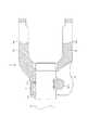
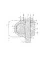
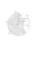
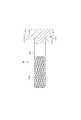
図1は本発明の実施例1のフランジ付き六角ボルトを有する自在継手を備えたステアリング装置の全体側面図、図2は本発明の実施例1のフランジ付き六角ボルトを有する自在継手の拡大正面図である。図3はボルトを強く締め付ける前の状態を示す図2のA−A断面図、図4は図3のB−B断面図である。図5はボルトを強く締め付けた後の状態を示す図2のA−A断面図である。 1 is an overall side view of a steering apparatus having a universal joint having a flanged hexagon bolt according to a first embodiment of the present invention, and FIG. 2 is an enlarged front view of the universal joint having a flanged hexagon bolt according to a first embodiment of the present invention. It is. 3 is a cross-sectional view taken along the line AA in FIG. 2 showing a state before the bolt is strongly tightened, and FIG. 4 is a cross-sectional view taken along the line BB in FIG. FIG. 5 is a cross-sectional view taken along line AA of FIG. 2 showing a state after the bolt is strongly tightened.
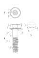
図6は図5のボルトのフランジと六角頭を断面した状態を示す断面図、図7は図6のP部拡大断面図である。図8(a)は本発明の実施例1のボルトを示す正面図、図8(b)は図8(a)のC−C断面図、図8(c)は図8(a)のQ部拡大断面図である。図9は本発明の実施例1のボルトのフランジと六角頭を断面した状態を示す一部断面正面図である。 6 is a cross-sectional view showing a state in which the flange and the hexagon head of the bolt of FIG. 5 are cut, and FIG. 7 is an enlarged cross-sectional view of a P portion of FIG. 8A is a front view showing the bolt of Example 1 of the present invention, FIG. 8B is a cross-sectional view taken along the line C-C in FIG. 8A, and FIG. 8C is Q in FIG. 8A. FIG. FIG. 9 is a partial cross-sectional front view showing a state in which the flange and the hexagon head of the bolt according to the first embodiment of the present invention are cut.
図1に示すように、本発明の実施例1のフランジ付き六角ボルトを有する自在継手備えたステアリング装置は、車体後方側(図1の右側)にステアリングホイール11を装着可能なステアリングシャフト12と、このステアリングシャフト12を挿通したステアリングコラム13と、このステアリングシャフト12に補助トルクを付与する為のアシスト装置(操舵補助部)20と、このステアリングシャフト12の車体前方側(図1の左側)に、図示しないラック/ピニオン機構を介して連結されたステアリングギヤ30とを備える。 As shown in FIG. 1, a steering device having a universal joint having a hexagon bolt with a flange according to the first embodiment of the present invention includes a
ステアリングシャフト12は、雌ステアリングシャフト12Aと雄ステアリングシャフト12Bとを、回転トルクを伝達可能に、かつ軸方向に関して相対移動可能にスプライン嵌合している。従って、上記雌ステアリングシャフト12Aと雄ステアリングシャフト12Bとは、衝突時に、このスプライン嵌合部が相対移動して、全長を縮めることができる。 The
また、上記ステアリングシャフト12を挿通した筒状のステアリングコラム13は、アウターコラム13Aとインナーコラム13Bとをテレスコピック移動可能に組み合わせている。そのため、ステアリングコラム13は、衝突時に軸方向の衝撃が加わった場合に、この衝撃によるエネルギを吸収しつつ全長が縮まる、所謂コラプシブル構造としている。 The
そして、上記インナーコラム13Bの車体前方側端部を、ギヤハウジング21の車体後方側端部に圧入嵌合して固定している。また、上記雄ステアリングシャフト12Bの車体前方側端部を、このギヤハウジング21の内側に通し、アシスト装置20の図示しない入力軸の車体後方側端部に連結している。 The vehicle body front side end portion of the
ステアリングコラム13は、その中間部を支持ブラケット14により、ダッシュボードの下面等、車体18の一部に支承している。また、この支持ブラケット14と車体18との間に、図示しない係止部を設けて、この支持ブラケット14に車体前方側に向かう方向の衝撃が加わった場合に、この支持ブラケット14が上記係止部から外れ、車体前方側に移動するようにしている。 The
また、上記ギヤハウジング21の上端部も、上記車体18の一部に支承している。また、本実施例の場合には、チルト機構及びテレスコピック機構を設けることにより、上記ステアリングホイール11の車体前後方向位置、及び、高さ位置の調節を自在としている。このようなチルト機構及びテレスコピック機構は、従来から周知であり、本発明の特徴部分でもない為、詳しい説明は省略する。 The upper end portion of the
上記ギヤハウジング21の車体前方側端面から突出した出力軸23は、自在継手(上側自在継手)41を介して、中間シャフト15の後端部に連結している。また、この中間シャフト15の前端部に、別の自在継手(下側自在継手)42を介して、ステアリングギヤ30のピニオン軸(以下軸と呼ぶ)6を連結している。中間シャフト15は、雄中間シャフト(雄シャフト)15Aの車体前方側に、雌中間シャフト(雌シャフト)15Bの車体後方側が外嵌し、回転トルクを伝達可能に、かつ、軸方向に関して相対移動可能に嵌合している。 The
図示しないピニオンが、軸6の下端(車体前方側端部)に形成されている。また、図示しないラックが、このピニオンに噛み合っており、ステアリングホイール11の回転が、タイロッド31を移動させて、図示しない車輪を操舵する。 A pinion (not shown) is formed at the lower end (front end of the vehicle body) of the
アシスト装置20のギヤハウジング21には、電動モータ26のケース261が固定され、この電動モータ26の図示しない回転軸にウォームが結合されている。出力軸23には図示しないウォームホイールが取り付けられ、このウォームホイールに電動モータ26の回転軸のウォームが噛合っている。 A
また、出力軸23の中間部の周囲には、図示しないトルクセンサが設けられている。上記ステアリングホイール11からステアリングシャフト12に加えられるトルクの方向と大きさを、トルクセンサで検出し、この検出値に応じて、電動モータ26を駆動し、ウォームとウォームホイールから成る減速機構を介して、出力軸23に、所定の方向に所定の大きさで補助トルクを発生させる。補助トルクを発生させるアシスト装置は、電動式に限定されるものではなく、油圧式のアシスト装置でもよい。 A torque sensor (not shown) is provided around the intermediate portion of the
図2から図7は、本発明の実施例1のフランジ付き六角ボルトを有する自在継手を示し、図1の自在継手42の一方のヨーク7と軸6との結合部に適用した例を示す。本発明のフランジ付き六角ボルトを有する自在継手は、図1の自在継手41と雄中間シャフト15Aとの結合部や、自在継手41と出力軸23との結合部に適用してもよい。 FIGS. 2 to 7 show a universal joint having a flanged hexagon bolt according to the first embodiment of the present invention, and shows an example in which the
図2から図7は、本発明の実施例1のフランジ付き六角ボルトを有する自在継手42を構成する一対のヨーク7、7のうちの一方のヨーク7と、軸6との結合部を示している。ヨーク7の左側には略円筒状の結合筒部71が形成され、この結合筒部71の内周面に形成された雌セレーション711に、図2、図4の左側から、結合筒部71の軸方向に平行に軸6を挿入する。そして、軸6の外周面に形成された雄セレーション61を、雌セレーション711にセレーション係合させて、回転トルクを伝達可能に構成している。 FIGS. 2 to 7 show a joint portion between one of the pair of
ヨーク7の右側には、結合筒部71と一体に設けられた一対の結合アーム部76、76が形成され、この結合アーム部76、76には、十字軸77を軸支するための軸受け孔761、761が形成されている。 A pair of
ヨーク7の結合筒部71には、結合筒部71から接線方向に延びた左右一対のフランジ部72A、72Bが形成されている。フランジ部72A、72Bの間には、雌セレーション711に連通するスリット(切り割り)73が形成されている。スリット73は、結合筒部71の軸方向の全長にわたって形成されている。 The
一対のフランジ部72A、72Bのうちの一方(図3の右側)のフランジ部72Aには、図8に示すボルト(フランジ付き六角ボルト)81を挿入するためのボルト孔74が形成され、他方のフランジ部72Bには、雌ねじ75が形成されている。雌ねじ75はボルト孔74と同心状に形成されている。 A
雌ねじ75には、ボルト81のボルト軸部811の左側に形成された雄ねじ812がねじ込まれる。また、フランジ部72Aには、ボルト孔74の開口部側(図3の右側)に平坦な座面741が形成されている。図8に示すように、ボルト軸部811の右側には、円盤状フランジ813が付いた六角頭814が形成されている。円盤状フランジ813の直径は、六角頭814の対角距離よりも大きく形成されて、座面の面積を大きくしている。 A
円盤状フランジ813の座面815には、平坦な座面815の外周に、凹凸部816が環状に形成されている。凹凸部816は円盤状フランジ813の外周縁817まで形成されている。また、凹凸部816は三角形に形成され、凸部の高さが円盤状フランジ813の座面815から突出しない高さに形成されている。凹凸部816は環状形状をしているため、ボルト81を成形する時に、パンチとダイスを使用した圧造によって、同時に成形し易い形状をしている。 On the
図3に示すように、ボルト81を締め付けると、円盤状フランジ813の平坦な座面815がフランジ部72Aの平坦な座面741と面で接触する。凹凸部816の凸部の高さが、円盤状フランジ813の座面815から突出しない高さに形成されているため、凹凸部816がフランジ部72Aの座面741に食い込むことはない。従って、ここまでは、凹凸部816の無いボルトと同一で、締付けトルクの変動が小さく、ボルトの締付け軸力が安定する。 As shown in FIG. 3, when the
図5から図7に示すように、ボルト81を更に締め付けると、フランジ部72Aの座面741が傾斜し、円盤状フランジ813の凹凸部816がフランジ部72Aの座面741の傾斜根元部(図5から図7の上部)に食い込み始める。凹凸部816は三角形に形成されているため、三角形の角が座面741に食い込んで、ボルト81の回り止めを効果的に行うことができる。ボルト81の締め付が完了すると、ボルト81の円盤状フランジ813の座面815に対して、フランジ部72Aの座面741が角度αだけ傾斜し、円盤状フランジ813の凹凸部816がフランジ部72Aの座面741に食い込む。 As shown in FIGS. 5 to 7, when the
従って、締付けの途中では締付けトルクの変動が小さく、締付けが完了すると、円盤状フランジ813の凹凸部816がフランジ部72Aの座面741に食い込み、締付け後のボルト81の回り止めをすることができる。本発明の実施例1では、締付けが完了する直前に、凹凸部816がフランジ部72Aの座面741に食い込むため、フランジ部72Aの座面741の傷が最小に抑えられ、自在継手の再利用が可能となる。 Accordingly, the fluctuation of the tightening torque is small during the tightening, and when the tightening is completed, the
ヨーク7の材質としては、冷間圧延鋼板(SPCC、SPCD)、機械構造用炭素鋼鋼材(SC)、鋳鉄(FC)等が使用される。ボルト81の材質としては、炭素鋼などのSC材、冷間圧造用炭素鋼線(SWCH)等が使用され、ヨーク7よりも硬度の高い材質を使用して、凹凸部816の食い込みを容易にし、ボルト81の回り止めの効果を大きくすることが好ましい。 As the material of the
次に本発明の実施例2について説明する。図10(a)は本発明の実施例2のボルトを示す正面図、図10(b)は図10(a)のD−D断面図、図10(c)は図10(a)のR部拡大断面図である。以下の説明では、上記実施例1と異なる構造部分についてのみ説明し、重複する説明は省略する。また、同一部品には同一番号を付して説明する。 Next, a second embodiment of the present invention will be described. 10A is a front view showing a bolt according to the second embodiment of the present invention, FIG. 10B is a cross-sectional view taken along the line DD in FIG. 10A, and FIG. 10C is an R in FIG. 10A. FIG. In the following description, only structural parts different from those of the first embodiment will be described, and redundant description will be omitted. Further, the same parts will be described with the same numbers.
実施例2は、円盤状フランジ813の凹凸部の形状を変更した例である。すなわち、図10に示すように、実施例2のボルト81は実施例1と同様に、ボルト81のボルト軸部811の左側には雄ねじ812が形成され、ボルト軸部811の右側には、円盤状フランジ813が付いた六角頭814が形成されている。円盤状フランジ813の直径は、六角頭814の対角距離よりも大きく形成されて、座面の面積を大きくしている。 Example 2 is an example in which the shape of the uneven portion of the disk-shaped
円盤状フランジ813の座面815には、平坦な座面815の外周に、凹凸部818が環状に形成されている。凹凸部818は円盤状フランジ813の外周縁817まで形成されている。実施例2では、凹凸部818は台形に形成され、凸部の高さが円盤状フランジ813の座面815から突出しない高さに形成されている。凹凸部818は環状形状をしているため、ボルト81を成形する時に、パンチとダイスを使用した圧造によって、同時に成形し易い形状をしている。 On the
実施例2では、凹凸部818が台形に形成され、凸部の先端がエッジになっていない。従って、ボルト81を締め付けて、凹凸部818をフランジ部72Aの座面741の傾斜根元部に食い込ませた時に、実施例1の三角形と比較して、フランジ部72Aの座面741の傷が小さく抑えられ、実施例1よりも自在継手の再利用が可能となる。 In Example 2, the
本発明の実施例2においても、締付けの途中では締付けトルクの変動が小さく、締付けが完了すると、円盤状フランジ813の凹凸部818がフランジ部72Aの座面741に食い込み、締付け後のボルト81の回り止めをすることができる。 Also in the second embodiment of the present invention, the fluctuation of the tightening torque is small during the tightening, and when the tightening is completed, the
上記実施例では、略円筒状の結合筒部71が形成されたヨークに本発明を適用した例について説明したが、略コの字断面の結合筒部を有するヨークに本発明を適用してもよい。また、上記実施例では、フランジ部72A、72Bの一方に雌ねじを形成し、ボルト軸部811の雄ねじ812をこの雌ねじにねじ込んで、フランジ部72A、72Bを締め付けるねじ込みボルト方式に本発明を適用した例について説明した。他の例として、ヨークのフランジ部72A、72Bの両方にボルト孔(バカ孔)を形成し、ボルトとナットでフランジ部72A、72Bを挟んで締め付ける通しボルト方式に本発明を適用してもよい。 In the above embodiment, the example in which the present invention is applied to the yoke in which the substantially cylindrical
11 ステアリングホイール
12 ステアリングシャフト
12A 雌ステアリングシャフト
12B 雄ステアリングシャフト
13 ステアリングコラム
13A アウターコラム
13B インナーコラム
14 支持ブラケット
15 中間シャフト
15A 雄中間シャフト
15B 雌中間シャフト
18 車体
20 アシスト装置
21 ギヤハウジング
23 出力軸
26 電動モータ
261 ケース
30 ステアリングギヤ
31 タイロッド
41 自在継手(上側自在継手)
42 自在継手(下側自在継手)
6 軸(ピニオン軸)
61 雄セレーション
7 ヨーク
71 結合筒部
711 雌セレーション
72A フランジ部
72B フランジ部
73 スリット(切り割り)
74 ボルト孔
741 座面
75 雌ねじ
76 結合アーム部
761 軸受け孔
77 十字軸
81 ボルト
811 ボルト軸部
812 雄ねじ
813 円盤状フランジ
814 六角頭
815 座面
816 凹凸部
817 外周縁
818 凹凸部DESCRIPTION OF SYMBOLS 11
42 Universal joint (lower universal joint)
6 axis (pinion axis)
61
74
Claims (3)
Translated fromJapanese上記フランジ付き六角ボルトは、上記円盤状フランジの座面の外周に環状に形成されて、凸部の高さが円盤状フランジの座面から突出しない高さに形成された凹凸部を有し、
上記フランジ付き六角ボルトによる上記一対のフランジ部の締め付けでは、上記凹凸部と上記円盤状フランジの座面は上記一対のフランジ部の平坦な座面に接触し、上記フランジ付き六角ボルトのさらなる締め付けで上記凹凸部が上記一対のフランジ部の一方の座面が上記円盤状フランジの座面に対して傾斜して上記一方の座面に食い込んで上記フランジ付き六角ボルトを回り止めすること
を特徴とする一対のフランジ部とフランジ付き六角ボルト組合せ体。Acrossa pair of flange portions formed to sandwich the cut-split, and flanged hex bolt hex head of the discoidal flange is formed male screwis formed at the other end at one end,the flanged hex boltthe cut-split ininserted into the bolt hole formed in one of the pair of flange portions formed,Nde threaded into a female screw formed onthe otherfor performing the tighteningof the pair of flangeportions, hexagonal witha pair of flange portions and the flange A boltcombination,
The flanged hexagon bolt is formed in an annular shape on the outer periphery of the seat surface of the disc-shaped flange, and has an uneven portion formed so that the height of the convex portion does not protrude from the seat surface of the disc-shaped flange,
In the tightening of the pair of flange portions with the flanged hexagon bolts, the concave and convex portions and the seat surface of the disk-shaped flange are in contact with the flat seating surfaces of the pair of flange portions. The concave and convex portions are configured such thatone seating surface of the pair of flange portions isinclined with respect to the seating surface of the disk-shaped flange and bites into the one seating surface to prevent the flanged hexagon bolt from rotating.Combination of apair of flanges and flanged hexagon bolts.
上記凹凸部が三角形に形成されていること
を特徴とする一対のフランジ部とフランジ付き六角ボルト組合せ体。Inthe pair of flanges and flanged hex boltcombination as described in claim 1,
Acombination of apair of flange portions and a hexagon bolt witha flange, wherein the concave and convex portions are formed in a triangular shape.
上記凹凸部が台形に形成されていること
を特徴とする一対のフランジ部とフランジ付き六角ボルト組合せ体。Inthe pair of flanges and flanged hex boltcombination as described in claim 1,
Acombination of apair of flange portions and a hexagon bolt witha flange, wherein the uneven portion is formed in a trapezoidal shape.
Priority Applications (4)
| Application Number | Priority Date | Filing Date | Title |
|---|---|---|---|
| JP2011098266AJP5533776B2 (en) | 2011-04-26 | 2011-04-26 | Pair of flange and flanged hexagon bolt combination |
| CN201120530768.1UCN202579584U (en) | 2011-04-26 | 2011-12-16 | Hexagon bolt with flange |
| US13/362,519US20120275878A1 (en) | 2011-04-26 | 2012-01-31 | Flanged Hexagon Head Bolt |
| EP12153446AEP2518339A1 (en) | 2011-04-26 | 2012-02-01 | Flanged hexagon head bolt |
Applications Claiming Priority (1)
| Application Number | Priority Date | Filing Date | Title |
|---|---|---|---|
| JP2011098266AJP5533776B2 (en) | 2011-04-26 | 2011-04-26 | Pair of flange and flanged hexagon bolt combination |
Publications (2)
| Publication Number | Publication Date |
|---|---|
| JP2012229749A JP2012229749A (en) | 2012-11-22 |
| JP5533776B2true JP5533776B2 (en) | 2014-06-25 |
Family
ID=45554539
Family Applications (1)
| Application Number | Title | Priority Date | Filing Date |
|---|---|---|---|
| JP2011098266AActiveJP5533776B2 (en) | 2011-04-26 | 2011-04-26 | Pair of flange and flanged hexagon bolt combination |
Country Status (4)
| Country | Link |
|---|---|
| US (1) | US20120275878A1 (en) |
| EP (1) | EP2518339A1 (en) |
| JP (1) | JP5533776B2 (en) |
| CN (1) | CN202579584U (en) |
Families Citing this family (1)
| Publication number | Priority date | Publication date | Assignee | Title |
|---|---|---|---|---|
| US12427872B2 (en)* | 2022-11-02 | 2025-09-30 | Ford Global Technologies, Llc | Traction battery pack coating clearing feature and coating clearing method |
Family Cites Families (39)
| Publication number | Priority date | Publication date | Assignee | Title |
|---|---|---|---|---|
| US2931411A (en)* | 1956-06-08 | 1960-04-05 | Thomas D Keehan | Screw fastener |
| BE572004A (en)* | 1958-06-18 | |||
| GB1050351A (en)* | 1959-05-06 | |||
| US3245449A (en)* | 1964-04-09 | 1966-04-12 | Nat Lock Co | Speaker mounting screw |
| US3752203A (en)* | 1971-07-28 | 1973-08-14 | Hill Fastener Corp | Lock-screw fasteners |
| DE7731901U1 (en)* | 1977-10-15 | 1978-03-09 | Fa. Richard Bergner, 8540 Schwabach | Self-locking head screw or nut |
| US4223711A (en)* | 1978-07-03 | 1980-09-23 | Russell, Burdsall & Ward Corporation | Self-locking fastener |
| US4220188A (en)* | 1978-07-10 | 1980-09-02 | Russell, Burdsall & Ward Corporation | Locking fastener |
| US4310272A (en)* | 1980-01-18 | 1982-01-12 | Textron Inc. | Threaded fastener and structural joint attained therewith |
| US4518294A (en)* | 1982-03-18 | 1985-05-21 | Illinois Tool Works Inc. | Rotary fastener |
| US4498825A (en)* | 1982-09-27 | 1985-02-12 | Russell, Burdsall & Ward Corporation | Load indicating flange |
| US4842463A (en)* | 1984-12-10 | 1989-06-27 | Sps Technologies, Inc. | Vibration resistant fasteners |
| US4812095A (en)* | 1987-02-24 | 1989-03-14 | Emhart Industries, Inc. | Threaded fastener |
| US4930960A (en)* | 1988-05-13 | 1990-06-05 | Slater Electric Inc. | Mounting arrangement for electrical wiring devices having non-metallic mounting strap |
| JP2534772B2 (en)* | 1989-07-07 | 1996-09-18 | 日本精工株式会社 | Universal joint yoke manufacturing method |
| JP2508575Y2 (en)* | 1990-04-12 | 1996-08-28 | 日本精工株式会社 | Universal joint yoke |
| US5297890A (en)* | 1992-02-20 | 1994-03-29 | Simpson Strong-Tie Company, Inc. | Wood-to-pipe connection |
| US5356253A (en)* | 1992-04-29 | 1994-10-18 | Whitesell Neil L | Sheet metal screw |
| US5403111A (en)* | 1993-07-09 | 1995-04-04 | The Torrington Company | Yoke clamp |
| US5580180A (en)* | 1995-05-01 | 1996-12-03 | The Torrington Company | One-piece stamped clamp yoke |
| US5628578A (en)* | 1995-07-28 | 1997-05-13 | Dana Corporation | Alternate pinch bolt yoke construction |
| DE19615191C5 (en)* | 1996-04-17 | 2006-02-09 | Sfs Intec Holding Ag | Screw and method for torque limited mounting of metal and / or plastic profiles or plates on a substructure |
| JP2000062622A (en)* | 1998-08-21 | 2000-02-29 | Toyoda Gosei Co Ltd | Steering wheel |
| US7014386B1 (en)* | 1998-01-15 | 2006-03-21 | Wayne-Dalton Corp. | Screw connection of components to sheet material and method of effecting connection |
| US6908270B1 (en)* | 1999-07-12 | 2005-06-21 | Iwata Bolt Kabushiki Kaisha | Self-locking bolt |
| JP2001234917A (en)* | 2000-02-23 | 2001-08-31 | Iwata Bolt Kk | Self-locking bolt |
| DE10001857A1 (en)* | 2000-01-18 | 2001-07-19 | Schatz Gmbh | Screw, nut or washer for screw connection has annular contact surface, protuberance surrounded by grooves |
| JP2002155920A (en)* | 2000-11-16 | 2002-05-31 | Ebara Corp | Nut tightening and fixing structure |
| US8092131B2 (en)* | 2001-07-19 | 2012-01-10 | Whitesell International Corporation | Clinch spacer and method of attaching the same to a panel |
| DE10138222A1 (en)* | 2001-08-03 | 2003-02-13 | Hilti Ag | screw head |
| USD482957S1 (en)* | 2002-11-12 | 2003-12-02 | The Peelle Company | Self-tapping bolt |
| JP3095134U (en)* | 2003-01-08 | 2003-07-25 | イワタボルト株式会社 | Detent bolt |
| CN100376811C (en)* | 2004-02-27 | 2008-03-26 | 刘玉恩 | Method of locking fastening device with screw thread and equipment |
| US7306418B2 (en)* | 2004-09-27 | 2007-12-11 | General Motors Corporation | Deforming member and captive fastener retaining method |
| US20090200435A1 (en)* | 2005-02-14 | 2009-08-13 | Duggan Daniel C | Hanger rod stiffening clip |
| TWM296931U (en)* | 2006-03-24 | 2006-09-01 | Chiou-Yue Wang | Screw |
| JP2008208923A (en)* | 2007-02-27 | 2008-09-11 | Mazda Motor Corp | Yoke shaft joint structure |
| US20110064540A1 (en)* | 2009-09-17 | 2011-03-17 | Mirco Walther | Screw having underside cutters and pockets |
| KR20110048279A (en)* | 2009-11-02 | 2011-05-11 | 현대자동차주식회사 | Panel fastening bolt and panel fastening method using the same |
- 2011
- 2011-04-26JPJP2011098266Apatent/JP5533776B2/enactiveActive
- 2011-12-16CNCN201120530768.1Upatent/CN202579584U/ennot_activeExpired - Lifetime
- 2012
- 2012-01-31USUS13/362,519patent/US20120275878A1/ennot_activeAbandoned
- 2012-02-01EPEP12153446Apatent/EP2518339A1/ennot_activeWithdrawn
Also Published As
| Publication number | Publication date |
|---|---|
| US20120275878A1 (en) | 2012-11-01 |
| JP2012229749A (en) | 2012-11-22 |
| EP2518339A1 (en) | 2012-10-31 |
| CN202579584U (en) | 2012-12-05 |
Similar Documents
| Publication | Publication Date | Title |
|---|---|---|
| JP2008030499A (en) | Wheel steering device | |
| JP4968114B2 (en) | Universal joint | |
| JP5088387B2 (en) | Cross shaft type universal joint | |
| JP5176349B2 (en) | Steering device | |
| JP6471552B2 (en) | Retaining ring and worm reducer | |
| JP5273129B2 (en) | Joint and shaft connection structure | |
| JP5533776B2 (en) | Pair of flange and flanged hexagon bolt combination | |
| JP6471478B2 (en) | Torque transmission unit | |
| JP2012021594A (en) | Joint structure of male shaft and female shaft | |
| JP4899728B2 (en) | Column-type electric power steering device | |
| JP2008303980A (en) | Fitting | |
| JP6464560B2 (en) | Universal joint and steering apparatus including the universal joint | |
| JP2009204030A (en) | Screw fastening mechanism | |
| JP5152033B2 (en) | Universal joint and processing method thereof | |
| JP5218434B2 (en) | Universal joint | |
| JP2015110988A (en) | Joint-shaft coupling structure | |
| JP5141160B2 (en) | Joint structure of yoke and rotating shaft in steering device | |
| JP5370201B2 (en) | Universal joint yoke | |
| JP5120294B2 (en) | Universal joint and processing method thereof | |
| JP5445660B2 (en) | Steering device | |
| JP6596958B2 (en) | Universal joint and steering apparatus including the universal joint | |
| JP5024401B2 (en) | Universal joint | |
| JP2009222148A (en) | Joint | |
| JP5636828B2 (en) | Universal joint and processing method thereof | |
| JP2017136903A (en) | Rack shaft for steering device and manufacturing method thereof |
Legal Events
| Date | Code | Title | Description |
|---|---|---|---|
| A977 | Report on retrieval | Free format text:JAPANESE INTERMEDIATE CODE: A971007 Effective date:20130411 | |
| A131 | Notification of reasons for refusal | Free format text:JAPANESE INTERMEDIATE CODE: A131 Effective date:20130416 | |
| A521 | Request for written amendment filed | Free format text:JAPANESE INTERMEDIATE CODE: A523 Effective date:20130513 | |
| A131 | Notification of reasons for refusal | Free format text:JAPANESE INTERMEDIATE CODE: A131 Effective date:20131203 | |
| A521 | Request for written amendment filed | Free format text:JAPANESE INTERMEDIATE CODE: A523 Effective date:20140115 | |
| TRDD | Decision of grant or rejection written | ||
| A01 | Written decision to grant a patent or to grant a registration (utility model) | Free format text:JAPANESE INTERMEDIATE CODE: A01 Effective date:20140401 | |
| R150 | Certificate of patent or registration of utility model | Ref document number:5533776 Country of ref document:JP Free format text:JAPANESE INTERMEDIATE CODE: R150 | |
| A61 | First payment of annual fees (during grant procedure) | Free format text:JAPANESE INTERMEDIATE CODE: A61 Effective date:20140414 | |
| R250 | Receipt of annual fees | Free format text:JAPANESE INTERMEDIATE CODE: R250 |