JP5533727B2 - Work picking system - Google Patents
Work picking systemDownload PDFInfo
- Publication number
- JP5533727B2 JP5533727B2JP2011033086AJP2011033086AJP5533727B2JP 5533727 B2JP5533727 B2JP 5533727B2JP 2011033086 AJP2011033086 AJP 2011033086AJP 2011033086 AJP2011033086 AJP 2011033086AJP 5533727 B2JP5533727 B2JP 5533727B2
- Authority
- JP
- Japan
- Prior art keywords
- workpiece
- unit
- axis
- hand
- gripping
- Prior art date
- Legal status (The legal status is an assumption and is not a legal conclusion. Google has not performed a legal analysis and makes no representation as to the accuracy of the status listed.)
- Active
Links
Images


Classifications
- B—PERFORMING OPERATIONS; TRANSPORTING
- B25—HAND TOOLS; PORTABLE POWER-DRIVEN TOOLS; MANIPULATORS
- B25J—MANIPULATORS; CHAMBERS PROVIDED WITH MANIPULATION DEVICES
- B25J13/00—Controls for manipulators
- B25J13/08—Controls for manipulators by means of sensing devices, e.g. viewing or touching devices
- B—PERFORMING OPERATIONS; TRANSPORTING
- B25—HAND TOOLS; PORTABLE POWER-DRIVEN TOOLS; MANIPULATORS
- B25J—MANIPULATORS; CHAMBERS PROVIDED WITH MANIPULATION DEVICES
- B25J15/00—Gripping heads and other end effectors
- B25J15/0004—Gripping heads and other end effectors with provision for adjusting the gripped object in the hand
- B—PERFORMING OPERATIONS; TRANSPORTING
- B25—HAND TOOLS; PORTABLE POWER-DRIVEN TOOLS; MANIPULATORS
- B25J—MANIPULATORS; CHAMBERS PROVIDED WITH MANIPULATION DEVICES
- B25J15/00—Gripping heads and other end effectors
- B25J15/0028—Gripping heads and other end effectors with movable, e.g. pivoting gripping jaw surfaces
- B—PERFORMING OPERATIONS; TRANSPORTING
- B25—HAND TOOLS; PORTABLE POWER-DRIVEN TOOLS; MANIPULATORS
- B25J—MANIPULATORS; CHAMBERS PROVIDED WITH MANIPULATION DEVICES
- B25J9/00—Programme-controlled manipulators
- B25J9/16—Programme controls
- B25J9/1612—Programme controls characterised by the hand, wrist, grip control
- B—PERFORMING OPERATIONS; TRANSPORTING
- B25—HAND TOOLS; PORTABLE POWER-DRIVEN TOOLS; MANIPULATORS
- B25J—MANIPULATORS; CHAMBERS PROVIDED WITH MANIPULATION DEVICES
- B25J9/00—Programme-controlled manipulators
- B25J9/16—Programme controls
- B25J9/1679—Programme controls characterised by the tasks executed
- B25J9/1682—Dual arm manipulator; Coordination of several manipulators
- B—PERFORMING OPERATIONS; TRANSPORTING
- B25—HAND TOOLS; PORTABLE POWER-DRIVEN TOOLS; MANIPULATORS
- B25J—MANIPULATORS; CHAMBERS PROVIDED WITH MANIPULATION DEVICES
- B25J9/00—Programme-controlled manipulators
- B25J9/16—Programme controls
- B25J9/1694—Programme controls characterised by use of sensors other than normal servo-feedback from position, speed or acceleration sensors, perception control, multi-sensor controlled systems, sensor fusion
- B25J9/1697—Vision controlled systems
- G—PHYSICS
- G05—CONTROLLING; REGULATING
- G05B—CONTROL OR REGULATING SYSTEMS IN GENERAL; FUNCTIONAL ELEMENTS OF SUCH SYSTEMS; MONITORING OR TESTING ARRANGEMENTS FOR SUCH SYSTEMS OR ELEMENTS
- G05B2219/00—Program-control systems
- G05B2219/30—Nc systems
- G05B2219/39—Robotics, robotics to robotics hand
- G05B2219/39465—Two fingers each with 2-DOF
- G—PHYSICS
- G05—CONTROLLING; REGULATING
- G05B—CONTROL OR REGULATING SYSTEMS IN GENERAL; FUNCTIONAL ELEMENTS OF SUCH SYSTEMS; MONITORING OR TESTING ARRANGEMENTS FOR SUCH SYSTEMS OR ELEMENTS
- G05B2219/00—Program-control systems
- G05B2219/30—Nc systems
- G05B2219/39—Robotics, robotics to robotics hand
- G05B2219/39476—Orient hand relative to object
- G—PHYSICS
- G05—CONTROLLING; REGULATING
- G05B—CONTROL OR REGULATING SYSTEMS IN GENERAL; FUNCTIONAL ELEMENTS OF SUCH SYSTEMS; MONITORING OR TESTING ARRANGEMENTS FOR SUCH SYSTEMS OR ELEMENTS
- G05B2219/00—Program-control systems
- G05B2219/30—Nc systems
- G05B2219/39—Robotics, robotics to robotics hand
- G05B2219/39488—Each finger gets 1-DOF, one more movement, translation or rotation
- G—PHYSICS
- G05—CONTROLLING; REGULATING
- G05B—CONTROL OR REGULATING SYSTEMS IN GENERAL; FUNCTIONAL ELEMENTS OF SUCH SYSTEMS; MONITORING OR TESTING ARRANGEMENTS FOR SUCH SYSTEMS OR ELEMENTS
- G05B2219/00—Program-control systems
- G05B2219/30—Nc systems
- G05B2219/39—Robotics, robotics to robotics hand
- G05B2219/39543—Recognize object and plan hand shapes in grasping movements
- G—PHYSICS
- G05—CONTROLLING; REGULATING
- G05B—CONTROL OR REGULATING SYSTEMS IN GENERAL; FUNCTIONAL ELEMENTS OF SUCH SYSTEMS; MONITORING OR TESTING ARRANGEMENTS FOR SUCH SYSTEMS OR ELEMENTS
- G05B2219/00—Program-control systems
- G05B2219/30—Nc systems
- G05B2219/40—Robotics, robotics mapping to robotics vision
- G05B2219/40053—Pick 3-D object from pile of objects
Landscapes
- Engineering & Computer Science (AREA)
- Robotics (AREA)
- Mechanical Engineering (AREA)
- Human Computer Interaction (AREA)
- Health & Medical Sciences (AREA)
- General Health & Medical Sciences (AREA)
- Orthopedic Medicine & Surgery (AREA)
- Manipulator (AREA)
Description
Translated fromJapanese本発明は、ワークピッキングシステムに関する。 The present invention relates to a work picking system.
従来、乱雑に重なり合って置かれたワークを、多軸ロボットの終端可動部に設けられたハンドによって把持して移動させる動作、すなわち、ピック動作を行うワークピッキングシステムが知られている。 2. Description of the Related Art Conventionally, there is known a work picking system that performs an operation of gripping and moving a workpiece placed in a messy manner with a hand provided on a terminal movable portion of a multi-axis robot, that is, a pick operation.
かかるワークピッキングシステムでは、ワークのそれぞれの位置を2次元計測器や、3次元計測器を用いて計測することによって次に把持するワークを決定し、決定したワークを把持するように多軸ロボットへ指示する。そして、多軸ロボットは、把持したワークを所定の位置へ移載する(たとえば、特許文献1参照)。 In such a workpiece picking system, a workpiece to be gripped next is determined by measuring each position of the workpiece using a two-dimensional measuring instrument or a three-dimensional measuring instrument, and the multi-axis robot is held so as to grip the determined workpiece. Instruct. Then, the multi-axis robot transfers the gripped work to a predetermined position (for example, see Patent Document 1).
しかしながら、上記した従来のワークピッキングシステムでは、ハンドによって把持されるワークの把持姿勢がばらつくという問題があった。このため、従来のワークピッキングシステムでは、ピック動作につづく動作を行いにくかった。 However, the conventional work picking system described above has a problem that the gripping posture of the work gripped by the hand varies. For this reason, in the conventional work picking system, it is difficult to perform the operation following the pick operation.
たとえば、ハンドによって把持されたワークの把持姿勢がバラバラである場合、ワークを所定の姿勢へ変更するためには、ハンド自体の姿勢を変更する必要があるので多軸ロボットの動作が複雑化してしまう。 For example, when the gripping posture of the workpiece gripped by the hand is different, it is necessary to change the posture of the hand itself in order to change the workpiece to a predetermined posture, which complicates the operation of the multi-axis robot. .
開示の技術は、上記に鑑みてなされたものであって、把持対象となるワークの姿勢に関わらず、ワークの把持姿勢を一定に保つことができるワークピッキングシステムを提供することを目的とする。 The disclosed technology has been made in view of the above, and an object of the present invention is to provide a workpiece picking system capable of keeping a workpiece gripping posture constant regardless of the posture of a workpiece to be gripped.
本願の開示するワークピッキングシステムは、第1および第2の多軸ロボットを双腕とし、鉛直向きと略平行な旋回軸まわりに旋回する胴部を有する双腕ロボットと、前記第1の多軸ロボットの終端可動部に設けられ、把持爪の間隔を変更する機構および前記把持爪の先端向きを変更する機構を含むハンドと、前記双腕ロボットから独立して固定され、前記第2の多軸ロボットによって把持された容器内にバラ積みされたワークの3次元形状を上方から計測する3次元計測部と、前記3次元計測部によって計測された前記3次元形状に基づいて前記ワークの姿勢を算出する算出部と、前記算出部によって算出された前記ワークの姿勢および前記終端可動部の回転軸の方向に基づいて前記把持爪の先端向きを決定する決定部と、前記3次元計測部と前記容器との距離が前記第1の多軸ロボットの作業スペースを確保した距離よりも小さい状態で前記3次元計測部による計測が完了した場合に、前記双腕ロボットに対し、前記旋回軸まわりの旋回によって前記容器を前記第1の多軸ロボットの作業スペースが確保される位置へ位置付かせる動作を指示した後に、前記終端可動部の回転軸の向きおよび前記決定部によって決定された前記把持爪の先端向きを保持しつつ前記ワークを把持する動作を指示する指示部とを備える。The work picking system disclosed in the present application includes a first arm and a second multi-axis robot as dual arms, and a double-arm robot having a trunk that rotates around a rotation axis substantially parallel to the vertical direction, and the first multi-axis robot. provided at the end movable part of the robot, the hand, including a mechanism for changing the mechanism to change the spacing of the gripping claws and forward-facing of the gripping clawsis fixed independently of the double-arm robot, the second polyaxial orientation of the workpiece based on the three-dimensional shape of roses stacked been workpiecegripped container by the robot andthree-dimensional measurement unitthat be measured from above, the three-dimensional shape measured by the three-dimensional measuring unit a calculation unit for calculating a, a determination unit for determining a front end facing the gripping claws on the basis of the direction of the axis of rotation of the posture and the end movable part of the workpiece calculated by the calculation section,the three-dimensional measurement Wherein when the measurement by the three-dimensional measurement unitwith a smaller state than the distance distance to ensure a working space of the first multi-axis robot of the container is completed, the relative double-armrobot, before Symbol pivotaxis After instructing the operation of positioning the container toa position where the work space of the first multi-axis robot is secured by turning around, the direction of the rotation axis of the terminal movable unit and the determination unit determined by the determination unit An instruction unit for instructing an operation of gripping the workpiece while holding the tip of the gripping claw.
本願の開示するワークピッキングシステムの一つの態様によれば、把持対象となるワークの姿勢に関わらず、ワークの把持姿勢を一定に保ったピック動作を行うことができる。 According to one aspect of the workpiece picking system disclosed in the present application, it is possible to perform a picking operation in which the gripping posture of the workpiece is kept constant regardless of the posture of the workpiece to be gripped.
以下、添付図面を参照して、本願の開示するワークピッキングシステムの実施例を詳細に説明する。なお、以下に示す各実施例における例示で本発明が限定されるものではない。 Hereinafter, embodiments of a work picking system disclosed in the present application will be described in detail with reference to the accompanying drawings. In addition, this invention is not limited by the illustration in each Example shown below.
また、以下では、3次元計測器を多軸ロボットとは別に固定して設けた場合の実施例を実施例1として、3次元計測器を多軸ロボットに設けた場合の実施例を実施例2として、それぞれ説明する。 In the following, an embodiment in which the three-dimensional measuring instrument is provided separately from the multi-axis robot is referred to as an embodiment 1, and an embodiment in which the three-dimensional measuring instrument is provided in the multi-axis robot is described as an embodiment 2. Each will be described.
まず、実施例1に係るワークピッキング方法について、図1を用いて説明する。図1は、実施例1に係るワークピッキング方法の説明図である。なお、以下では、把持対象となるワーク100が「ボルト」である場合について説明するが、ワーク100の種別はこれに限定されない。たとえば、ワーク100は、ナットや電子部品であってもよい。 First, the work picking method according to the first embodiment will be described with reference to FIG. FIG. 1 is an explanatory diagram of a work picking method according to the first embodiment. In the following, a case where the
また、図1では、3次元計測器による計測方向が、鉛直下向き(以下、「鉛直方向」と記載する)である場合について示している。そして、図1では、説明をわかりやすくする観点から、直交座標系であるxy座標系を水平面上に設け、ワーク100の基準軸(ここでは、ボルトの軸心を結んだ軸)を水平面へ投影した線をy軸としている。 FIG. 1 shows a case where the measurement direction by the three-dimensional measuring instrument is vertically downward (hereinafter referred to as “vertical direction”). In FIG. 1, an xy coordinate system, which is an orthogonal coordinate system, is provided on a horizontal plane for easy understanding of the explanation, and a reference axis (here, an axis connecting bolt axes) is projected onto the horizontal plane. The drawn line is the y-axis.
図1に示すように、実施例1に係るワークピッキング方法では、多軸ロボットの終端可動部(図1に示す「アーム」参照)に設けられた「ハンド」によってワーク100を把持して移動させる動作(ピック動作)を行う。 As shown in FIG. 1, in the work picking method according to the first embodiment, the
ここで、「ハンド」は、先端向きを変更可能な1対の把持爪を備えており、ピッキングするワーク100の姿勢に応じて把持爪の先端向きを適宜変更することによって、把持爪とワーク100の相対姿勢を一定に保つ。 Here, the “hand” includes a pair of gripping claws whose tip orientation can be changed, and the gripping claws and the
なお、1対の把持爪は、図1に示す軸AXp(以下、「ピック軸AXp」と記載する)まわりに回転することによって、把持爪の先端向きを任意の向きへ変更する。また、ハンドが取り付けられたアームは、図1に示す軸AXtまわりに回転するが、軸AXtは、鉛直方向と略平行な姿勢を保つように制御される。 Note that the pair of grip claws rotate about the axis AXp (hereinafter referred to as “pick axis AXp”) shown in FIG. 1 to change the tip direction of the grip claws to an arbitrary direction. Further, the arm to which the hand is attached rotates around the axis AXt shown in FIG. 1, but the axis AXt is controlled so as to maintain a posture substantially parallel to the vertical direction.
すなわち、実施例1に係るワークピッキング方法では、多軸ロボットの終端可動部の回転軸を鉛直方向と略平行に保ちつつ、ハンドの把持爪の先端向きがワーク100の基準軸となす角を一定(たとえば、90度)にしたピック動作を行う。 In other words, in the workpiece picking method according to the first embodiment, the angle between the tip direction of the gripping claw of the hand and the reference axis of the
したがって、実施例1に係るワークピッキング方法によれば、把持爪に対するワーク100の姿勢を各ピック動作にわたって一定に保つことができるので、把持したワーク100に関する次の作業(たとえば、ボルトの軸を穴に挿入する作業)が行いやすい。 Therefore, according to the work picking method according to the first embodiment, the posture of the
また、実施例1に係るワークピッキング方法によれば、ハンドが設けられたアームの回転軸の向きを鉛直方向と略平行に保つことができるので、アームと障害物(たとえば、ワーク100をバラ積みした容器)との接触が発生しにくい。 In addition, according to the work picking method according to the first embodiment, the direction of the rotation axis of the arm provided with the hand can be kept substantially parallel to the vertical direction, so that the arm and the obstacle (for example, the
以下、実施例1に係るワークピッキング方法の手順について説明する。図1に示すように、実施例1に係るワークピッキング方法では、バラ積みされたワーク100を3次元計測し、ピック対象となるワーク100を決定するとともに、ワーク100の位置および姿勢を取得する(図1の(a)参照)。ここで、ワーク100の基準軸と水平面とのなす角度が、図1に示すように「θ」であるとする。 Hereinafter, the procedure of the work picking method according to the first embodiment will be described. As shown in FIG. 1, in the workpiece picking method according to the first embodiment, the
この場合、実施例1に係るワークピッキング方法では、ピック軸AXpが、図1に示すx軸と略平行になるように、アームを軸AXtまわりに回転させる(図1の(b1)参照)。また、実施例に係るワークピッキング方法では、ワーク100の姿勢に応じて把持爪をピック軸AXpまわりに回転させる(図1の(b2)参照)。 In this case, in the work picking method according to the first embodiment, the arm is rotated around the axis AXt so that the pick axis AXp is substantially parallel to the x axis shown in FIG. 1 (see (b1) in FIG. 1). In the work picking method according to the embodiment, the gripping claw is rotated around the pick axis AXp according to the posture of the work 100 (see (b2) in FIG. 1).
ここで、図1に示すように、把持爪の先端向きとアームの回転軸である軸AXtとのなす角を上記した「θ」と等しくすれば、把持爪の先端向きとワーク100の基準軸とを直交させることができる。 Here, as shown in FIG. 1, if the angle formed between the tip direction of the gripping claw and the axis AXt that is the rotation axis of the arm is equal to the above-mentioned “θ”, the tip direction of the gripping claw and the reference axis of the
なお、図1では、把持爪の先端向きとワーク100の基準軸とが直交するピック動作を例示したが、把持爪の先端向きとワーク100の基準軸とが所定の角度αとなるようにピック動作を行うこととしてもよい。この場合、把持爪の先端向きと軸AXtとのなす角が「θ+α」あるいは「θ−α」となるように、把持爪をピック軸AXpまわりに回転させることとすればよい。 1 illustrates a pick operation in which the tip direction of the gripping claw and the reference axis of the
ここで、図1に示した(b1)および(b2)の手順の実行順序に関しては、どちらの手順から実行してもよく、かかる2つの手順を並行して実行することとしてもよい。 Here, regarding the execution order of the procedures (b1) and (b2) shown in FIG. 1, the procedure may be executed from either procedure, or the two procedures may be executed in parallel.
このように、実施例1に係るワークピッキング方法では、把持爪の先端向きをワーク100の姿勢に応じて適宜調整したうえで、1対の把持爪間の間隔を狭める把持動作によってワーク100を把持する(図1の(c)参照)。 As described above, in the work picking method according to the first embodiment, the tip of the gripping claw is appropriately adjusted according to the posture of the
次に、実施例1に係るワークピッキングシステム1について説明する。図2は、実施例1に係るワークピッキングシステム1のブロック図である。図2に示すように、ワークピッキングシステム1は、3次元計測部10と、ハンド20と、ロボット30と制御装置40とを備える。なお、ハンド20は、図1に示した「ピック軸付きハンド」を指す。 Next, the work picking system 1 according to the first embodiment will be described. FIG. 2 is a block diagram of the work picking system 1 according to the first embodiment. As shown in FIG. 2, the work picking system 1 includes a three-
また、制御装置40は、制御部41と、記憶部42とを備えており、制御部41は、3次元情報取得部41aと、ワーク姿勢算出部41bと、把持爪向き決定部41cと、指示部41dとをさらに備える。そして、記憶部42は、3次元情報42aと、ワーク情報42bとを記憶する。 The
なお、図2では、ハンド20とロボット30とを独立した構成要素として記載したが、ロボット30にハンド20を含め、制御装置40の指示部41dがハンド20に対する指示についてもロボット30へ指示することとしてもよい。また、図2では、1つの制御装置40を示したが、制御装置40を複数の独立した装置としたうえで、各装置が相互に通信するように構成してもよい。 In FIG. 2, the
3次元計測部10は、ワーク100の3次元形状を計測するデバイス(3次元計測器)である。この3次元計測部10としては、たとえば、レーザスリット光を用いたスキャン動作によって、物体の3次元形状の取得を行う計測ユニットを用いることができる。 The three-
ハンド20は、図1に示したように、先端向きを適宜調整可能な1対の把持爪で把持動作を行うピック軸付きハンドである。なお、ハンドの具体的な構成例については、図6を用いて後述する。ロボット30は、たとえば、7軸の多軸ロボットであり、終端可動部には、上記したハンド20が設けられる。すなわち、ロボット30は、ハンドなどのエンドエフェクタを交換可能な汎用ロボットである。 As shown in FIG. 1, the
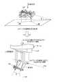
ここで、実施例1に係るワークピッキングシステム1の配置例について図3を、実施例1に係るロボット30の各軸について図4を、それぞれ用いて説明しておく。図3は、実施例1に係るワークピッキングシステム1の配置図である。図3に示すように、3次元計測部10は、鉛直方向(鉛直下向き)側が計測領域となるように、スタンド11(支持部)を介して固定される。 Here, an arrangement example of the work picking system 1 according to the first embodiment will be described with reference to FIG. 3, and each axis of the
また、図3に示すように、ロボット30は、右アーム30aと、左アーム30bとを双腕とする、いわゆる双腕ロボットである。ここで、右アーム30aおよび左アーム30bは、それぞれが、多軸ロボット(図3では7軸ロボット)であり、左アーム30bのエンドエフェクタとして、上記したハンド20(ピック軸付きハンド)が設けられる。 As shown in FIG. 3, the
なお、右アーム30aには、所定のエンドエフェクタが設けられ、ワーク100がバラ積みされた容器200を把持する。このように、ロボット30は、右アーム30aで把持した容器200から、左アーム30bに設けられたハンド20でワーク100をつまみ出す動作を行う。 The
なお、ロボット30は、右アーム30aおよび左アーム30bが設けられた胴部30cを、床面などに固定される支持部30dに対して水平面に沿って旋回させる機構を有している。 Note that the
図4は、7軸ロボットにおける各軸の説明図である。なお、図4に示す各関節の回転軸の向きは、円で示した関節については紙面と垂直であり、矩形で示した関節については紙面と平行である。なお、図4には、各関節の回転向きを両矢印で示している。また、図3に示した右アーム30aおよび左アーム30bのそれぞれを、図4に示した7軸ロボットとすることができる。 FIG. 4 is an explanatory diagram of each axis in the seven-axis robot. The direction of the rotation axis of each joint shown in FIG. 4 is perpendicular to the paper surface for the joint indicated by a circle, and is parallel to the paper surface for the joint indicated by a rectangle. In FIG. 4, the rotation direction of each joint is indicated by a double arrow. Further, each of the
図4に示すように、各関節の回転軸は、設置基準面から順に、軸AXs、軸AXl、軸AXe、軸AXu、軸AXr、軸AXbおよび軸AXtである。そして、軸AXtは、7軸ロボットの終端可動部の回転軸に相当し、終端可動部にはエンドエフェクタが設けられる。なお、右アーム30aおよび左アーム30bの軸構成は、図4に例示した構成に限られない。 As shown in FIG. 4, the rotation axes of the joints are an axis AXs, an axis AX1, an axis AXe, an axis AXu, an axis AXr, an axis AXb, and an axis AXt in order from the installation reference plane. The axis AXt corresponds to the rotation axis of the terminal movable part of the seven-axis robot, and the terminal movable part is provided with an end effector. The shaft configurations of the
ここで、実施例1に係るハンド20(図3参照)が設けられた左アーム30b(図3参照)は、軸AXtを鉛直方向と略平行に保持した状態でハンド20によるピック動作を実行する。 Here, the
図2の説明に戻り、制御装置40について説明する。制御部41は、制御装置40の全体制御を行う。3次元情報取得部41aは、3次元計測部10から計測データを受け取り、受け取った計測データを、3次元情報42aとして記憶部42へ記憶させる。ここで、3次元情報42aは、1つまたは複数のワーク100の3次元形状を示す情報である。 Returning to the description of FIG. 2, the
ワーク姿勢算出部41bは、3次元情報42aおよびワーク情報42bに基づいてピック動作の対象となるワーク100の姿勢を算出する処理を行う。ここで、ワーク情報42bは、ワーク100の3次元形状や被把持部位を定義した情報である。 The workpiece
なお、「被把持部位」としては、たとえば、ワーク100がボルトである場合には、ボルトの頭部近傍の軸が定義される。このように、ボルトの頭部近傍の軸を被把持部位とするのは、ボルトをバラ積みした状態では、頭部近傍付近に空隙が生じやすいためである。 For example, when the
ワーク姿勢算出部41bは、ワーク情報42bを用いたマッチング処理を行うことによって、3次元情報42aからワーク100を検出する。そして、ワーク姿勢算出部41bは、検出したワーク100の中から次にピッキングするワーク100を決定し、決定したワーク100の姿勢を算出する。なお、ワーク姿勢算出部41bは、ワーク100における被把持部位の位置も併せて算出する。 The workpiece
そして、把持爪向き決定部41cは、ワーク姿勢算出部41bによって算出されたワーク100の姿勢に基づき、ハンド20における把持爪の先端向きを決定する。また、把持爪向き決定部41cは、決定した先端向きを、指示部41dに対して通知する。 Then, the gripping claw
ここで、ハンド20(ピック軸付きハンド)の模式構成について、図5を用いて説明しておく。図5は、ハンド20の模式構成を示す図である。なお、図5の(A)には、ハンド20の模式構成を、図5の(B)には、把持爪の先端向きを変更した様子を、同じく(C)には、ワーク100における基準軸101と把持爪の先端向きとの関係を、それぞれ示している。 Here, a schematic configuration of the hand 20 (hand with a pick shaft) will be described with reference to FIG. FIG. 5 is a diagram illustrating a schematic configuration of the
図5の(A)に示すように、ハンド20は、スライダ軸21に沿って移動可能なスライダ21aおよびスライダ21bをそれぞれ含んだ1対の移動部22を備える。そして、移動部22には、関節23経由で把持爪24がそれぞれ取り付けられる。なお、把持爪24の先端は、点24aである。 As shown in FIG. 5A, the
ここで、1対の移動部22が、スライダ軸21に沿ってお互いに接近する向きへ移動する動作によって、1対の把持爪24がワーク100を挟み込み、お互いに遠ざかる向きへ移動する動作によって、1対の把持爪24で挟み込んだワーク100を解放する。 Here, by the operation in which the pair of moving
また、図5の(A)に示すように、把持爪24は、関節23を支点として、両矢印で示した向きに回転する。なお、2つの関節23を結んだ線は、上記したピック軸AXpである。また、図5の(A)には、移動部22および把持爪24が1つの直線上にある状態、すなわち、把持爪24の基準姿勢を示している。 Further, as shown in FIG. 5A, the
図5の(B)には、図5の(A)に示した基準姿勢から、1対の把持爪24をピック軸AXpまわりに所定角度だけ回転させた状態を例示している。ここで、ピック軸AXpと、2つの点24a(把持爪24の各先端)とを含んだ平面を平面50とし、平面50の法線を法線51とする。 FIG. 5B illustrates a state in which the pair of
この場合、図5の(C)に示したように、ハンド20がワーク100を把持する際には、法線51と、ワーク100の基準軸101とが略平行となるように、把持爪24の先端向きを調整する。このようにすることで、把持爪24の向きが、ワーク100の基準軸101と略直交した状態で、ワーク100を把持することが可能となる。 In this case, as shown in FIG. 5C, when the
なお、図5の(C)には、把持爪24の向きと、ワーク100の基準軸101とを略直交させる場合を示したが、把持爪24の向きと、ワーク100の基準軸101とのなす角については、任意の角度とすることができる。 5C shows a case where the orientation of the
図2の説明に戻り、制御装置40の説明をつづける。指示部41dは、把持爪向き決定部41cによって決定された把持爪向きをハンド20に対して指示する。また、指示部41dは、ピック動作に伴うハンド20の移動をロボット30に対して指示する。 Returning to the description of FIG. 2, the description of the
ここで、指示部41dは、ハンド20が取り付けられた終端可動部の回転軸(図1の軸AXt参照)が、鉛直方向と略平行となる姿勢を保持するように、ロボット30に対して指示する。また、指示部41dは、3次元計測部10に対する計測開始指示を適宜行うが、計測開始指示のタイミングについては、図8を用いて後述する。 Here, the
記憶部42は、ハードディスクドライブや不揮発性メモリといった記憶デバイスであり、3次元情報42aおよびワーク情報42bを記憶する。なお、3次元情報42aおよびワーク情報42bの内容については、既に説明したので、ここでの説明を省略する。 The
なお、図2では、制御装置40を1つの装置として説明したが、制御装置40を複数の独立した装置として構成することとしてもよい。たとえば、3次元計測部10を制御する計測制御装置と、ハンド20およびロボット30を制御するロボット制御装置と、計測制御装置およびロボット制御装置を統括する統括制御装置とが相互に通信する構成をとってもよい。 In FIG. 2, the
次に、ハンド20(ピック軸付きハンド)の構成例について図6を用いて説明する。図6は、ハンド20の構成例を示す図である。なお、図6の(A)には、左アーム30b(図3参照)に取り付けられた状態のハンド20を、図6の(B)には、ハンド20の構成例を、それぞれ示している。 Next, a configuration example of the hand 20 (hand with a pick shaft) will be described with reference to FIG. FIG. 6 is a diagram illustrating a configuration example of the
図6の(A)に示すように、左アーム30bの終端可動部31には、ハンド20が取り付けられる。また、ハンド20における上記したピック軸AXpは、終端可動部31の回転軸である軸AXtと略直交する。 As shown in FIG. 6A, the
図6の(B)に示すように、ハンド20は、把持爪24の開閉に用いられる第1のサーボモータ61aと、把持爪24の先端向きの変更に用いられる第2のサーボモータ62aとを備える。また、ハンド20は、1対の移動部22と、1対の把持爪24とを備える。 As shown in FIG. 6B, the
第1のサーボモータ61aによる駆動力は、伝達機構61b経由で、左右ネジシャフト21へ伝達される。ここで、左右ネジシャフト21の一端側と他端側には、それぞれ逆向きのネジ(左右ネジ)が形成されている。 The driving force by the
また、1対の移動部22には、左右ネジシャフト21を貫通させる穴に、それぞれ同方向のネジが形成されている。したがって、1対の移動部22は、左右ネジシャフト21の回転に伴い、左右ネジシャフト21に沿ってそれぞれ逆方向へ移動する。 Further, in the pair of moving
また、第2のサーボモータ62aによる駆動力は、伝達機構62b経由で、図示しないスプラインシャフトへ伝達される。そして、スプラインシャフトの回転に伴って作動するリンク機構62dは、把持爪24にピック軸AXpにて連結された円板23を回転させる。これにより、把持爪24は、ピック軸AXpまわりに回転し、把持爪24の先端向きが変更される。 The driving force by the
このように、1対の把持爪24の間隔および先端向きは、それぞれ、サーボモータによって変更されるので、ワーク100を適切な姿勢、かつ、適切な把持力で把持することができる。また、ワーク100の被把持部位における厚み(たとえば、ボルトの軸径)を取得することができる。 As described above, since the distance between the pair of
次に、ハンド20(ピック軸付きハンド)によるピック動作について図7を用いて説明する。図7は、ハンド20によるピック動作の例を示す図である。なお、図7の(A)には、ワーク100を把持した把持爪24の動作例を、図7の(B)には、容器200と把持爪24との位置関係を、それぞれ示している。 Next, a picking operation by the hand 20 (hand with a pick shaft) will be described with reference to FIG. FIG. 7 is a diagram illustrating an example of a pick operation by the
また、図7の(A)および(B)では、説明を簡略化する観点から、ピック軸AXpが紙面と垂直となるように図示している。 7A and 7B, the pick axis AXp is illustrated to be perpendicular to the paper surface from the viewpoint of simplifying the description.
図7の(A)に示すように、終端可動部31の回転軸である軸AXtを、鉛直方向と略平行としたうえで、把持爪24は、ワーク100の基準軸101と直交する姿勢でワーク100を把持する。したがって、ワーク100を把持した把持爪24の先端向きを、軸AXtと略平行になるように変更すれば、ワーク100の基準軸101は、軸AXtと略直交する。 As shown in FIG. 7A, the
このように、ハンド20によれば、さまざまな姿勢でバラ積みされたワーク100であっても、終端可動部31の姿勢を保ったまま、ワーク100を一定の把持姿勢で把持することができる。さらに、ハンド20によれば、終端可動部31の姿勢を保ったまま、把持後のワーク100の姿勢を一定の姿勢(たとえば、水平状態)へ変更することができる。 As described above, according to the
また、図7の(B)に示すように、ハンド20によれば、左アーム30b(図3参照)ならびにハンド20を容器200に接触させることなく、容器200の壁面付近に位置するワーク100をつまみ出すことが可能となる。 Further, as shown in FIG. 7B, according to the
たとえば、図7の(B)における左側壁面近くのワーク100を把持する場合には、位置71にハンド20を位置付けたうえで、把持爪24の先端側が左側壁面に近づくように、把持爪24の先端向きを変更する。また、図7の(B)における右側壁面近くのワーク100を把持する場合には、位置72にハンド20を位置付けたうえで、把持爪24の先端側が右側壁面に近づくように、把持爪24の先端向きを変更する。 For example, when gripping the
次に、制御装置40の指示部41dによって行われる指示の例について、図8を用いて説明する。図8は、計測位置およびピック位置を示す図である。なお、図8の(A)には、計測位置およびピック位置を鉛直線上に配置する場合を、図8の(B)には、計測位置およびピック位置を水平線上に配置する場合を、それぞれ示している。また、図8には、3次元計測部10による計測向き81を示している。 Next, an example of an instruction given by the
図8の(A)に示すように、指示部41dは、容器200を把持した右アーム30aに対し、3次元計測部10の計測範囲に設けられた計測位置82に、容器200を位置付けるように指示する。 As shown in FIG. 8A, the
つづいて、指示部41dは、3次元計測部10に対して計測開始指示を行う。そして、3次元計測部10による計測が完了したならば、指示部41dは、右アーム30aに対し、容器200を鉛直方向(鉛直下向き)へ移動させてピック位置83へ位置付けるように指示する。 Subsequently, the
ここで、計測位置82に対応する距離hs(3次元計測部10から容器200の基準位置までの距離)は、ピック位置83に対応する距離hpよりも小さい。これは、3次元計測部10による計測精度が確保される距離で計測を行いつつ、ピック動作を行う左アーム30bの作業スペースを確保するためである。 Here, the distance hs corresponding to the measurement position 82 (the distance from the three-
また、計測位置82の鉛直方向(鉛直下向き)にピック位置83を設けるのは、容器200内のワーク100の位置ずれを防止するためである。 In addition, the
また、図8の(B)に示すように、計測位置82にて3次元計測部10による計測が完了した容器200を、水平向きに移動させてピック位置84あるいはピック位置85へ位置付けることとしてもよい。この場合、指示部41dは、図3に示した胴部30cを旋回させるようにロボット30に対して指示する。 Further, as shown in FIG. 8B, the
このように、水平向きに容器200を移動させることによっても、ピック動作を行う左アーム30bの作業スペースを確保することができる。 Thus, the work space of the
次に、実施例1に係るワークピッキングシステム1が実行する処理手順について図9を用いて説明する。図9は、実施例1に係るワークピッキングシステム1が実行する処理手順を示すフローチャートである。なお、図9における「右ハンド」は、図3における右アーム30aに設けられたハンドを、「左ハンド」は、図3における左アーム30bに設けられたハンド20(ピック軸付きハンド)を、それぞれ指す。 Next, a processing procedure executed by the work picking system 1 according to the first embodiment will be described with reference to FIG. FIG. 9 is a flowchart illustrating a processing procedure executed by the work picking system 1 according to the first embodiment. 9, the “right hand” indicates the hand provided on the
図9に示すように、指示部41dは、右ハンドにて容器200を測定位置へ位置付けるように指示する(ステップS101)。また、指示部41dは、3次元計測部10に対して3次元計測を実行するように指示する(ステップS102)。 As shown in FIG. 9, the
つづいて、ワーク姿勢算出部41bは、把持可能なワーク100があるか否かを判定する(ステップS103)。そして、把持可能なワーク100がある場合には(ステップS103,Yes)、把持爪向き決定部41cは、ワーク姿勢に基づいてハンド20における把持爪の先端向きを決定する(ステップS104)。 Subsequently, the workpiece
そして、指示部41dは、右ハンドにて容器200をピック位置へ位置付けるように指示し(ステップS105)、左ハンド(ハンド20)にてワーク100を把持するように指示する(ステップS106)。つづいて、指示部41dは、左ハンドにてワーク100を移載するように指示し(ステップS107)、所要ワークの移載が完了したか否かを判定する(ステップ108)。 Then, the
そして、所要ワークの移載が完了した場合には(ステップS108,Yes)、処理を終了する。一方、所要ワークの移載が完了していない場合には(ステップS108,No)、ステップS101以降の処理を繰り返す。なお、「所要ワーク」とは、たとえば、移載すべきワーク100の種別ごとの総数のことを指す。 If the transfer of the required workpiece is completed (step S108, Yes), the process is terminated. On the other hand, when the transfer of the required workpiece has not been completed (No at Step S108), the processes after Step S101 are repeated. The “required work” refers to, for example, the total number for each type of
ところで、ステップS103において把持可能なワーク100がないと判定された場合には(ステップS103,No)、容器200内の残ワーク(ワーク100の個数や総重量)が、規定値未満であるか否かを判定する(ステップS109)。そして、残ワークが規定値未満である場合には(ステップS109,Yes)、エラー報知を行ったうえで(ステップS110)、処理を終了する。 By the way, when it is determined that there is no
一方、ステップS109の判定条件を満たさなかった場合には(ステップS109,No)、指示部41dは、右ハンドにて容器200を揺動させるように指示し(ステップS111)、ステップS102以降の処理を繰り返す。なお、容器200を揺動させることで、容器200内のワーク100の位置がずれるため、把持可能なワーク100を増やすことができる。 On the other hand, when the determination condition of step S109 is not satisfied (step S109, No), the
なお、図9に示した、左ハンドによるワーク100の移載(ステップS107)と、右ハンドによる容器200の測定位置への移動(ステップS101)とを並行して行うこととしてもよい。 Note that the transfer of the
上述したように、実施例1に係るワークピッキングシステムは、把持対象であるワークの3次元形状を計測する3次元計測部と、多軸ロボットの終端可動部に設けられ、把持爪の間隔を変更する機構および把持爪の先端向きを変更する機構を含むハンドとを備える。また、実施例1に係るワークピッキングシステムは、3次元計測部によって計測された3次元形状に基づいてワークの姿勢を算出する算出部と、算出部によって算出されたワークの姿勢および終端可動部の回転軸の方向に基づいて把持爪の先端向きを決定する決定部とを備える。さらに、実施例1に係るワークピッキングシステムは、終端可動部の回転軸の向きおよび決定部によって決定された把持爪の先端向きを保持しつつワークを把持する動作を指示する指示部を備える。 As described above, the workpiece picking system according to the first embodiment is provided in the three-dimensional measurement unit that measures the three-dimensional shape of the workpiece to be gripped and the terminal movable unit of the multi-axis robot, and changes the interval between the gripping claws. And a hand including a mechanism for changing the tip direction of the gripping claw. In addition, the workpiece picking system according to the first embodiment includes a calculation unit that calculates the posture of the workpiece based on the three-dimensional shape measured by the three-dimensional measurement unit, the workpiece posture calculated by the calculation unit, and the terminal movable unit. And a determining unit that determines the tip direction of the gripping claw based on the direction of the rotation axis. Furthermore, the workpiece picking system according to the first embodiment includes an instruction unit that instructs an operation of gripping the workpiece while maintaining the direction of the rotation axis of the terminal movable unit and the tip direction of the gripping claw determined by the determination unit.
したがって、実施例1に係るワークピッキングシステムによれば、把持対象となるワークの姿勢に関わらず、ハンド自体の姿勢を変えることなくワークの把持姿勢を一定に保つことができる。 Therefore, according to the workpiece picking system according to the first embodiment, the workpiece gripping posture can be kept constant without changing the posture of the hand itself regardless of the posture of the workpiece to be gripped.
ところで、上述した実施例1では、3次元計測部を多軸ロボットとは別に固定して設けた場合について説明したが、3次元計測器を多軸ロボットに設けることとしてもよい。そこで、以下に示す実施例2では、3次元計測器を多軸ロボットに設けた場合について説明する。 In the first embodiment, the case where the three-dimensional measuring unit is provided separately from the multi-axis robot has been described. However, the three-dimensional measuring device may be provided in the multi-axis robot. In the second embodiment described below, a case where a three-dimensional measuring instrument is provided in a multi-axis robot will be described.
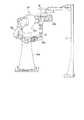
図10は、実施例2に係る3次元計測部10の配置を示す図である。なお、図10は、図6の(A)に対応しており、3次元計測部10が左アーム30bの終端可動部31に設けられている点以外は、図6の(A)と同様であるので、以下では、両者に共通する説明を省略する。 FIG. 10 is a diagram illustrating an arrangement of the three-
図10に示すように、3次元計測部10は、ハンド20が取り付けられた終端可動部31に設けられる。ここで、3次元計測部10は、ハンド20とともに軸AXtまわりに回転する部位に設けてもよいし、軸AXtまわりに回転しない部位に設けてもよい。 As shown in FIG. 10, the three-
また、図10に示すように、3次元計測部10は、計測向き81がハンド20の先端側を向くように終端可動部31に固定される。このように、ハンド20を備えた多軸ロボットに3次元計測部10を設けることで、ピック動作に関連するロボット30の動作をさらに簡略化することができる。 As shown in FIG. 10, the three-
また、3次元計測部10の計測範囲が狭い場合であっても、ワーク100を計測範囲に入れることが容易となる。 Further, even when the measurement range of the three-
次に、実施例2に係るワークピッキングシステム1が実行する処理手順について図11を用いて説明する。図11は、実施例2に係るワークピッキングシステム1が実行する処理手順を示すフローチャートである。なお、図11における「右ハンド」および「左ハンド」は、図9の説明と同様であるが、「左ハンド」には、図10に示したように3次元計測部10が設けられているものとする。 Next, a processing procedure executed by the work picking system 1 according to the second embodiment will be described with reference to FIG. FIG. 11 is a flowchart illustrating a processing procedure executed by the work picking system 1 according to the second embodiment. The “right hand” and the “left hand” in FIG. 11 are the same as those in FIG. 9, but the “left hand” is provided with the three-
図11に示すように、指示部41dは、右ハンドにて容器200をピック位置へ位置付けるように指示する(ステップS201)。また、指示部41dは、左ハンドに設けられた3次元計測部10に対して3次元計測を実行するように指示する(ステップS202)。 As shown in FIG. 11, the
つづいて、ワーク姿勢算出部41bは、把持可能なワーク100があるか否かを判定する(ステップS203)。そして、把持可能なワーク100がある場合には(ステップS203,Yes)、把持爪向き決定部41cは、ワーク姿勢に基づいてハンド20における把持爪の先端向きを決定する(ステップS204)。 Subsequently, the workpiece
そして、指示部41dは、左ハンド(ハンド20)にてワーク100を把持するように指示する(ステップS205)。つづいて、指示部41dは、左ハンドにてワーク100を移載するように指示し(ステップS206)、所要ワークの移載が完了したか否かを判定する(ステップ207)。 Then, the
そして、所要ワークの移載が完了した場合には(ステップS207,Yes)、処理を終了する。一方、所要ワークの移載が完了していない場合には(ステップS207,No)、ステップS201以降の処理を繰り返す。 If the transfer of the required workpiece is completed (step S207, Yes), the process is terminated. On the other hand, if the transfer of the required workpiece has not been completed (No at Step S207), the processes after Step S201 are repeated.
ところで、ステップS203において把持可能なワークがないと判定された場合には(ステップS203,No)、容器200内の残ワーク(ワーク100の個数や総重量)が規定値未満であるか否かを判定する(ステップS208)。そして、残ワークが規定値未満である場合には(ステップS208,Yes)、エラー報知を行ったうえで(ステップS209)、処理を終了する。 By the way, when it is determined in step S203 that there is no work that can be gripped (No in step S203), it is determined whether or not the remaining work (the number and the total weight of the work 100) in the
一方、ステップS209の判定条件を満たさなかった場合には(ステップS209,No)、指示部41dは、右ハンドにて容器200を揺動させるように指示し(ステップS210)、ステップS202以降の処理を繰り返す。 On the other hand, when the determination condition of step S209 is not satisfied (step S209, No), the
このように、実施例2に係るワークピッキングシステムは、先端向きを変更可能な把持爪を有するハンドが取り付けられた多軸ロボットに対して3次元計測部を設けたので、多軸ロボットによるピック動作を簡略化することができる。また、3次元計測部の計測範囲の広狭に関わらず、ワークの姿勢を確実に計測することができる。 As described above, since the work picking system according to the second embodiment is provided with the three-dimensional measuring unit for the multi-axis robot to which the hand having the gripping claw capable of changing the tip direction is attached, the pick operation by the multi-axis robot is performed. Can be simplified. In addition, the posture of the workpiece can be reliably measured regardless of the measurement range of the three-dimensional measurement unit.
なお、上述した各実施例では、双腕ロボットの右腕で容器を把持し、容器内のワークを左腕でつまみ出す場合について説明したが、左腕で容器を把持して右腕でピック動作を行ってもよい。また、ピック軸を備えたハンドが取り付けられた片腕ロボットでピック動作を行うこととしてもよい。 In each of the above-described embodiments, the case has been described in which the container is gripped by the right arm of the dual-arm robot and the workpiece in the container is picked up by the left arm. . Moreover, it is good also as performing a pick operation | movement with the one arm robot to which the hand provided with the pick axis | shaft was attached.
また、上述した各実施例では、容器内の残ワークが規定値未満となった場合に、容器を揺動させる場合について説明したが、3次元計測部による計測を省略しつつピック動作を連続して行うこととしてもよい。また、容器内に把持可能なワークが複数ある場合に、3次元計測部による計測を省略しつつピック動作を連続して行うこととしてもよい。 Further, in each of the above-described embodiments, the case has been described in which the container is swung when the remaining work in the container becomes less than the specified value. It may be done. Moreover, when there are a plurality of work pieces that can be held in the container, the picking operation may be continuously performed while omitting the measurement by the three-dimensional measurement unit.
また、上述した各実施例では、1対の把持爪を備えたハンドによるピック動作を例示したが、2対以上の把持爪を備えたハンド、すなわち、複数のピック軸を備えたハンドでピック動作を行うこととしてもよい。また、1つのピック軸について3つ以上の把持爪を設けたハンドでピック動作を行うこととしてもよい。 Further, in each of the above-described embodiments, the picking operation by a hand having a pair of gripping claws is illustrated, but the picking operation is performed by a hand having two or more pairs of gripping claws, that is, a hand having a plurality of pick axes. It is good also as performing. Moreover, it is good also as performing pick operation with the hand which provided the 3 or more holding nail | claw about one pick axis | shaft.
なお、上記した制御装置は、たとえば、コンピュータで構成することができる。この場合、制御部は、CPU(Central Processing Unit)であり、記憶部は、メモリである。また、制御部の各機能は、あらかじめ作成されたプログラムを制御部へロードして実行させることによって実現することができる。 Note that the control device described above can be configured by a computer, for example. In this case, the control unit is a CPU (Central Processing Unit), and the storage unit is a memory. Each function of the control unit can be realized by loading a program created in advance into the control unit and executing the program.
さらなる効果や変形例は、当業者によって容易に導き出すことができる。このため、本発明のより広範な態様は、以上のように表しかつ記述した特定の詳細および代表的な実施例に限定されるものではない。したがって、添付の特許請求の範囲およびその均等物によって定義される総括的な発明の概念の精神または範囲から逸脱することなく、様々な変更が可能である。 Further effects and modifications can be easily derived by those skilled in the art. Thus, the broader aspects of the present invention are not limited to the specific details and representative examples shown and described above. Accordingly, various modifications can be made without departing from the spirit or scope of the general inventive concept as defined by the appended claims and their equivalents.
1 ワークピッキングシステム
10 3次元計測部
20 ハンド(ピック軸付きハンド)
30 ロボット
40 制御装置
41 制御部
41a 3次元情報取得部
41b ワーク姿勢算出部
41c 把持爪向き決定部
41d 指示部
42 記憶部
42a 3次元情報
42b ワーク情報1
DESCRIPTION OF
Claims (5)
Translated fromJapanese前記第1の多軸ロボットの終端可動部に設けられ、把持爪の間隔を変更する機構および前記把持爪の先端向きを変更する機構を含むハンドと、
前記双腕ロボットから独立して固定され、前記第2の多軸ロボットによって把持された容器内にバラ積みされたワークの3次元形状を上方から計測する3次元計測部と、
前記3次元計測部によって計測された前記3次元形状に基づいて前記ワークの姿勢を算出する算出部と、
前記算出部によって算出された前記ワークの姿勢および前記終端可動部の回転軸の方向に基づいて前記把持爪の先端向きを決定する決定部と、
前記3次元計測部と前記容器との距離が前記第1の多軸ロボットの作業スペースを確保した距離よりも小さい状態で前記3次元計測部による計測が完了した場合に、前記双腕ロボットに対し、前記旋回軸まわりの旋回によって前記容器を前記第1の多軸ロボットの作業スペースが確保される位置へ位置付かせる動作を指示した後に、前記終端可動部の回転軸の向きおよび前記決定部によって決定された前記把持爪の先端向きを保持しつつ前記ワークを把持する動作を指示する指示部と
を備えることを特徴とするワークピッキングシステム。A double-arm robot having a first arm and a second multi-axis robot as double arms, and having a trunk portion that rotates around a rotation axis substantially parallel to the vertical direction;
A hand that is provided at a terminal movable portion of the first multi-axis robot and includes a mechanism for changing a gap between gripping claws and a mechanism for changing a tip direction of the gripping claws;
Said dual-arm is fixed independently of the robot, thethree-dimensional measuring unityou measure the three-dimensional shape of roses stacked been workpiecegripped container from above by a second multi-axis robot,
A calculation unit that calculates the posture of the workpiece based on the three-dimensional shape measured by the three-dimensional measurement unit;
A determination unit that determines the tip direction of the gripping claw based on the posture of the workpiece calculated by the calculation unit and the direction of the rotation axis of the terminal movable unit;
When the measurement by the three-dimensional measuring unit is completed in astate where the distance between the three-dimensional measuring unit and the container is smaller than the distance that secures the work space of the first multi-axis robot,, after instructing the operation to adhere positionto a position where the working space of the said containerfirst multi-axis robot is ensured by turning aroundbefore Symbol pivot axis orientation and the determination of the rotation axis of the end movable portion A work picking system comprising: an instruction unit for instructing an operation of gripping the work while holding a tip direction of the gripping nail determined by the step.
前記把持爪の支点間を結ぶ回転軸および前記把持爪の先端を含む面の法線方向が、前記ワークにおける基準軸と所定の角度をなすように前記把持爪の先端向きを決定することを特徴とする請求項1に記載のワークピッキングシステム。The determination unit
The tip direction of the gripping claw is determined such that a normal direction of a surface including a rotation axis connecting the supporting points of the gripping claw and a tip of the gripping claw forms a predetermined angle with a reference axis of the workpiece. The work picking system according to claim 1.
ボルトであり、
前記決定部は、
前記法線方向が前記ボルトにおける軸線方向と略並行となるように前記把持爪の先端向きを決定することを特徴とする請求項2に記載のワークピッキングシステム。The workpiece is
Bolt,
The determination unit
The workpiece picking system according to claim 2, wherein the tip direction of the gripping claw is determined so that the normal direction is substantially parallel to an axial direction of the bolt.
前記算出部が前記ワークの姿勢の算出に失敗した場合に、前記容器を揺する動作を前記第2の多軸ロボットに対して指示することを特徴とする請求項1、2または3に記載のワークピッキングシステム。The instruction unit includes:
The workpiece according to claim 1, 2, or 3, wherein when the calculation unit fails to calculate the posture of the workpiece, the second multi-axis robot is instructed to move the container. Picking system.
前記容器内のワークの残量が所定の閾値以下である場合に、前記3次元計測部によるあらたな計測を指示することなく、前記第1の多軸ロボットによる前記ワークのピック動作を指示することを特徴とする請求項1〜4のいずれか一つに記載のワークピッキングシステム。The instruction unit includes:
Instructing the pick operation of the workpiece by the first multi-axis robot without instructing a new measurement by the three-dimensional measurement unit when the remaining amount of the workpiece in the container is equal to or less than a predetermined threshold. The work picking system according to any one of claims 1 to 4.
Priority Applications (4)
| Application Number | Priority Date | Filing Date | Title |
|---|---|---|---|
| JP2011033086AJP5533727B2 (en) | 2011-02-18 | 2011-02-18 | Work picking system |
| US13/313,012US8948904B2 (en) | 2011-02-18 | 2011-12-07 | Work picking system |
| EP11193769.4AEP2489482A3 (en) | 2011-02-18 | 2011-12-15 | Work Picking System |
| CN201110436049.8ACN102642201B (en) | 2011-02-18 | 2011-12-22 | Work picking system |
Applications Claiming Priority (1)
| Application Number | Priority Date | Filing Date | Title |
|---|---|---|---|
| JP2011033086AJP5533727B2 (en) | 2011-02-18 | 2011-02-18 | Work picking system |
Publications (2)
| Publication Number | Publication Date |
|---|---|
| JP2012171027A JP2012171027A (en) | 2012-09-10 |
| JP5533727B2true JP5533727B2 (en) | 2014-06-25 |
Family
ID=45540744
Family Applications (1)
| Application Number | Title | Priority Date | Filing Date |
|---|---|---|---|
| JP2011033086AActiveJP5533727B2 (en) | 2011-02-18 | 2011-02-18 | Work picking system |
Country Status (4)
| Country | Link |
|---|---|
| US (1) | US8948904B2 (en) |
| EP (1) | EP2489482A3 (en) |
| JP (1) | JP5533727B2 (en) |
| CN (1) | CN102642201B (en) |
Families Citing this family (22)
| Publication number | Priority date | Publication date | Assignee | Title |
|---|---|---|---|---|
| DE102013013114A1 (en)* | 2012-08-17 | 2014-02-20 | Liebherr-Verzahntechnik Gmbh | Device for the automated removal of workpieces arranged in a container |
| US9391042B2 (en)* | 2012-12-14 | 2016-07-12 | Apple Inc. | Micro device transfer system with pivot mount |
| JP5765355B2 (en) | 2013-03-18 | 2015-08-19 | 株式会社安川電機 | Robot picking system and workpiece manufacturing method |
| JP6364856B2 (en)* | 2014-03-25 | 2018-08-01 | セイコーエプソン株式会社 | robot |
| JP6088563B2 (en)* | 2015-02-10 | 2017-03-01 | ファナック株式会社 | Work picking robot system having position and orientation conversion operation function, and work picking method |
| US9950863B2 (en) | 2015-02-25 | 2018-04-24 | Dematic Corp. | Automated order fulfillment system and method |
| JP6529302B2 (en)* | 2015-03-24 | 2019-06-12 | キヤノン株式会社 | INFORMATION PROCESSING APPARATUS, INFORMATION PROCESSING METHOD, AND PROGRAM |
| WO2017017710A1 (en)* | 2015-07-30 | 2017-02-02 | 川崎重工業株式会社 | Robot and control method therefor |
| JP2017035757A (en)* | 2015-08-11 | 2017-02-16 | ファナック株式会社 | Machining system with machine tool and robot attaching/detaching workpiece |
| JP2017181228A (en)* | 2016-03-30 | 2017-10-05 | キヤノン株式会社 | Measurement device, measurement method and manufacturing method of article |
| CN106915258B (en)* | 2017-01-18 | 2020-10-23 | 上海蔚来汽车有限公司 | Support bracket, picking workpiece and vehicle instrument panel |
| JP6438512B2 (en)* | 2017-03-13 | 2018-12-12 | ファナック株式会社 | ROBOT SYSTEM, MEASUREMENT DATA PROCESSING DEVICE, AND MEASUREMENT DATA PROCESSING METHOD FOR TAKE OUT WORK WITH MEASUREMENT DATA CORRECTED BY MACHINE LEARN |
| JP6859771B2 (en)* | 2017-03-16 | 2021-04-14 | トヨタ自動車株式会社 | Parts supply equipment |
| CN109108979A (en)* | 2018-09-14 | 2019-01-01 | 广东人励智能工程有限公司 | A kind of system and method for realizing servo drive control based on industrial robot |
| JP6858901B1 (en)* | 2020-03-30 | 2021-04-14 | 川田テクノロジーズ株式会社 | Hand for work robot |
| JP2022072563A (en)* | 2020-10-30 | 2022-05-17 | 日立Astemo株式会社 | Gripping device and visual inspection method |
| CN112847375B (en)* | 2021-01-22 | 2022-04-26 | 熵智科技(深圳)有限公司 | Workpiece grabbing method and device, computer equipment and storage medium |
| JP7725246B2 (en)* | 2021-06-04 | 2025-08-19 | 株式会社東芝 | Handling system, transport system, control device, program, and handling method |
| JP2023131485A (en)* | 2022-03-09 | 2023-09-22 | 株式会社日立製作所 | Picking device, and picking method |
| EP4400458A4 (en)* | 2022-11-30 | 2025-01-15 | Contemporary Amperex Technology (Hong Kong) Limited | PICKUP TOOL |
| CN219009183U (en)* | 2022-11-30 | 2023-05-12 | 宁德时代新能源科技股份有限公司 | Pick-up tool |
| CN116216305B (en)* | 2022-12-29 | 2023-11-07 | 长园视觉科技(珠海)有限公司 | Feeding and discharging control method, controller, feeding and discharging equipment and storage medium |
Family Cites Families (35)
| Publication number | Priority date | Publication date | Assignee | Title |
|---|---|---|---|---|
| US3888362A (en)* | 1973-05-31 | 1975-06-10 | Nasa | Cooperative multiaxis sensor for teleoperation of article manipulating apparatus |
| US4017721A (en)* | 1974-05-16 | 1977-04-12 | The Bendix Corporation | Method and apparatus for determining the position of a body |
| US4412293A (en)* | 1981-03-30 | 1983-10-25 | Kelley Robert B | Robot system which acquires cylindrical workpieces from bins |
| JPS61296409A (en)* | 1985-06-25 | 1986-12-27 | Fanuc Ltd | Robot control system |
| JP3064348B2 (en)* | 1990-08-02 | 2000-07-12 | 豊田工機株式会社 | Robot controller |
| JPH04109815U (en)* | 1991-02-28 | 1992-09-24 | ダイキン工業株式会社 | parts supply device |
| GB2261069B (en)* | 1991-10-30 | 1995-11-01 | Nippon Denso Co | High speed picking system for stacked parts |
| JPH10329065A (en)* | 1997-05-30 | 1998-12-15 | Matsushita Electric Ind Co Ltd | Compensation method for robot misalignment |
| JPH11300670A (en)* | 1998-04-21 | 1999-11-02 | Fanuc Ltd | Article picking-up device |
| JP3215086B2 (en)* | 1998-07-09 | 2001-10-02 | ファナック株式会社 | Robot controller |
| WO2000057129A1 (en)* | 1999-03-19 | 2000-09-28 | Matsushita Electric Works, Ltd. | Three-dimensional object recognition method and pin picking system using the method |
| JP3300682B2 (en)* | 1999-04-08 | 2002-07-08 | ファナック株式会社 | Robot device with image processing function |
| JP3865703B2 (en)* | 2002-10-25 | 2007-01-10 | ファナック株式会社 | Article conveying system and conveying method |
| JP2004160567A (en) | 2002-11-11 | 2004-06-10 | Fanuc Ltd | Article taking-out device |
| JP3805310B2 (en) | 2003-01-30 | 2006-08-02 | ファナック株式会社 | Work take-out device |
| JP3930490B2 (en)* | 2004-04-23 | 2007-06-13 | ファナック株式会社 | Article take-out device |
| CN101870112B (en)* | 2006-01-13 | 2011-09-28 | 松下电器产业株式会社 | Device for controlling robot arm |
| JP4087874B2 (en)* | 2006-02-01 | 2008-05-21 | ファナック株式会社 | Work picking device |
| JP4199264B2 (en)* | 2006-05-29 | 2008-12-17 | ファナック株式会社 | Work picking apparatus and method |
| US7313464B1 (en)* | 2006-09-05 | 2007-12-25 | Adept Technology Inc. | Bin-picking system for randomly positioned objects |
| JP4226623B2 (en)* | 2006-09-29 | 2009-02-18 | ファナック株式会社 | Work picking device |
| US20080181485A1 (en)* | 2006-12-15 | 2008-07-31 | Beis Jeffrey S | System and method of identifying objects |
| JP4309439B2 (en)* | 2007-03-30 | 2009-08-05 | ファナック株式会社 | Object take-out device |
| JP2009050987A (en)* | 2007-08-29 | 2009-03-12 | Toshiba Corp | Robot and control method thereof |
| US7983487B2 (en)* | 2007-11-07 | 2011-07-19 | Mitsubishi Electric Research Laboratories, Inc. | Method and system for locating and picking objects using active illumination |
| WO2009111575A2 (en) | 2008-03-05 | 2009-09-11 | Sri International | Substrates for silicon solar cells and methods of producing the same |
| JP4565023B2 (en)* | 2008-07-04 | 2010-10-20 | ファナック株式会社 | Article take-out device |
| JP5265296B2 (en)* | 2008-10-10 | 2013-08-14 | 本田技研工業株式会社 | Work removal method |
| US8559699B2 (en)* | 2008-10-10 | 2013-10-15 | Roboticvisiontech Llc | Methods and apparatus to facilitate operations in image based systems |
| JP5201411B2 (en) | 2008-11-21 | 2013-06-05 | 株式会社Ihi | Bulk picking device and control method thereof |
| JP5458274B2 (en)* | 2009-02-09 | 2014-04-02 | 本田技研工業株式会社 | Gripping position calculation device and gripping position calculation method |
| JP5293442B2 (en)* | 2009-06-18 | 2013-09-18 | 株式会社安川電機 | Robot system and article juxtaposition method |
| JP5333344B2 (en)* | 2009-06-19 | 2013-11-06 | 株式会社安川電機 | Shape detection apparatus and robot system |
| JP5402697B2 (en)* | 2009-10-26 | 2014-01-29 | 株式会社安川電機 | Robot apparatus, work picking system and work picking method |
| JP5489000B2 (en) | 2010-08-31 | 2014-05-14 | 株式会社安川電機 | Working device and component picking system |
- 2011
- 2011-02-18JPJP2011033086Apatent/JP5533727B2/enactiveActive
- 2011-12-07USUS13/313,012patent/US8948904B2/ennot_activeExpired - Fee Related
- 2011-12-15EPEP11193769.4Apatent/EP2489482A3/ennot_activeWithdrawn
- 2011-12-22CNCN201110436049.8Apatent/CN102642201B/ennot_activeExpired - Fee Related
Also Published As
| Publication number | Publication date |
|---|---|
| US20120215350A1 (en) | 2012-08-23 |
| JP2012171027A (en) | 2012-09-10 |
| CN102642201A (en) | 2012-08-22 |
| US8948904B2 (en) | 2015-02-03 |
| EP2489482A3 (en) | 2014-11-19 |
| EP2489482A2 (en) | 2012-08-22 |
| CN102642201B (en) | 2015-04-22 |
Similar Documents
| Publication | Publication Date | Title |
|---|---|---|
| JP5533727B2 (en) | Work picking system | |
| CN104044143B (en) | Robot system, bearing calibration and machined object manufacture method | |
| JP6484213B2 (en) | Robot system including a plurality of robots, robot control apparatus, and robot control method | |
| US10195744B2 (en) | Control device, robot, and robot system | |
| US20150127141A1 (en) | Robot, control device, robot system and robot control method | |
| CN104044131A (en) | Robot System, Calibration Method, And Method For Producing To-be-processed Material | |
| JP5250858B2 (en) | Multiple robot collision detection method and robot apparatus | |
| US10377043B2 (en) | Robot control apparatus, robot, and robot system | |
| JP2018176388A (en) | Calibration device | |
| US20200298417A1 (en) | Device, method and program for estimating weight and position of gravity center of load by using robot | |
| JP2015203567A (en) | Measuring system | |
| JP2019188514A (en) | Device, method, and program for estimating weight and centroid position of load using robot | |
| CN111037553B (en) | control device | |
| JP2014240106A (en) | Robot, robot control device, and driving method of robot | |
| JP6011089B2 (en) | Robot system and robot control apparatus and method | |
| JP7396829B2 (en) | Device, robot control device, robot system, and method for setting robot coordinate system | |
| JP4640499B2 (en) | Grip control device | |
| JP2015085499A (en) | Robot, robot system, control apparatus and control method | |
| JP2016209936A (en) | Robot apparatus, robot control method, program, and recording medium | |
| JP2017127932A (en) | Robot device, method for controlling robot, method for manufacturing component, program and recording medium | |
| KR102582430B1 (en) | A method and apparatus for controlling a robot using feedback from a laser tracker | |
| JP5353718B2 (en) | Control device, robot, robot system, and robot tracking control method | |
| JP2005335010A (en) | Grip control device | |
| US20210146542A1 (en) | Control method for robot system | |
| JP2016120534A (en) | Positioning system and welding system |
Legal Events
| Date | Code | Title | Description |
|---|---|---|---|
| A621 | Written request for application examination | Free format text:JAPANESE INTERMEDIATE CODE: A621 Effective date:20121227 | |
| A977 | Report on retrieval | Free format text:JAPANESE INTERMEDIATE CODE: A971007 Effective date:20130424 | |
| A131 | Notification of reasons for refusal | Free format text:JAPANESE INTERMEDIATE CODE: A131 Effective date:20130507 | |
| A02 | Decision of refusal | Free format text:JAPANESE INTERMEDIATE CODE: A02 Effective date:20131015 | |
| A521 | Request for written amendment filed | Free format text:JAPANESE INTERMEDIATE CODE: A523 Effective date:20131101 | |
| A911 | Transfer to examiner for re-examination before appeal (zenchi) | Free format text:JAPANESE INTERMEDIATE CODE: A911 Effective date:20131216 | |
| A131 | Notification of reasons for refusal | Free format text:JAPANESE INTERMEDIATE CODE: A131 Effective date:20140304 | |
| A521 | Request for written amendment filed | Free format text:JAPANESE INTERMEDIATE CODE: A523 Effective date:20140313 | |
| TRDD | Decision of grant or rejection written | ||
| A01 | Written decision to grant a patent or to grant a registration (utility model) | Free format text:JAPANESE INTERMEDIATE CODE: A01 Effective date:20140401 | |
| R150 | Certificate of patent or registration of utility model | Ref document number:5533727 Country of ref document:JP Free format text:JAPANESE INTERMEDIATE CODE: R150 | |
| A61 | First payment of annual fees (during grant procedure) | Free format text:JAPANESE INTERMEDIATE CODE: A61 Effective date:20140414 | |
| R250 | Receipt of annual fees | Free format text:JAPANESE INTERMEDIATE CODE: R250 |