JP5532295B2 - Motor control device and vehicle steering device - Google Patents
Motor control device and vehicle steering deviceDownload PDFInfo
- Publication number
- JP5532295B2 JP5532295B2JP2009258962AJP2009258962AJP5532295B2JP 5532295 B2JP5532295 B2JP 5532295B2JP 2009258962 AJP2009258962 AJP 2009258962AJP 2009258962 AJP2009258962 AJP 2009258962AJP 5532295 B2JP5532295 B2JP 5532295B2
- Authority
- JP
- Japan
- Prior art keywords
- torque
- control
- steering
- angle
- motor
- Prior art date
- Legal status (The legal status is an assumption and is not a legal conclusion. Google has not performed a legal analysis and makes no representation as to the accuracy of the status listed.)
- Expired - Fee Related
Links
Images


Classifications
- B—PERFORMING OPERATIONS; TRANSPORTING
- B62—LAND VEHICLES FOR TRAVELLING OTHERWISE THAN ON RAILS
- B62D—MOTOR VEHICLES; TRAILERS
- B62D5/00—Power-assisted or power-driven steering
- B62D5/04—Power-assisted or power-driven steering electrical, e.g. using an electric servo-motor connected to, or forming part of, the steering gear
- B62D5/0457—Power-assisted or power-driven steering electrical, e.g. using an electric servo-motor connected to, or forming part of, the steering gear characterised by control features of the drive means as such
- B62D5/046—Controlling the motor
- B62D5/0463—Controlling the motor calculating assisting torque from the motor based on driver input
- Y—GENERAL TAGGING OF NEW TECHNOLOGICAL DEVELOPMENTS; GENERAL TAGGING OF CROSS-SECTIONAL TECHNOLOGIES SPANNING OVER SEVERAL SECTIONS OF THE IPC; TECHNICAL SUBJECTS COVERED BY FORMER USPC CROSS-REFERENCE ART COLLECTIONS [XRACs] AND DIGESTS
- Y10—TECHNICAL SUBJECTS COVERED BY FORMER USPC
- Y10S—TECHNICAL SUBJECTS COVERED BY FORMER USPC CROSS-REFERENCE ART COLLECTIONS [XRACs] AND DIGESTS
- Y10S901/00—Robots
- Y10S901/30—End effector
- Y10S901/41—Tool
- Y10S901/42—Welding
Landscapes
- Engineering & Computer Science (AREA)
- Chemical & Material Sciences (AREA)
- Combustion & Propulsion (AREA)
- Transportation (AREA)
- Mechanical Engineering (AREA)
- Steering Control In Accordance With Driving Conditions (AREA)
- Power Steering Mechanism (AREA)
- Control Of Motors That Do Not Use Commutators (AREA)
- Control Of Ac Motors In General (AREA)
Description
Translated fromJapaneseこの発明は、ブラシレスモータを駆動するためのモータ制御装置およびそれを備えた車両用操舵装置に関する。車両用操舵装置の一例は、電動パワーステアリング装置である。 The present invention relates to a motor control apparatus for driving a brushless motor and a vehicle steering apparatus including the motor control apparatus. An example of a vehicle steering device is an electric power steering device.
ブラシレスモータを駆動制御するためのモータ制御装置は、一般に、ロータの回転角を検出するための回転角センサの出力に応じてモータ電流の供給を制御するように構成されている。回転角センサとしては、一般的には、ロータ回転角(電気角)に対応した正弦波信号および余弦波信号を出力するレゾルバが用いられる。しかし、レゾルバは、高価であり、配線数が多く、また、設置スペースも大きい。そのため、ブラシレスモータを備えた装置のコスト削減および小型化が阻害されるという課題がある。 A motor control device for driving and controlling a brushless motor is generally configured to control the supply of motor current in accordance with the output of a rotation angle sensor for detecting the rotation angle of the rotor. As the rotation angle sensor, a resolver that outputs a sine wave signal and a cosine wave signal corresponding to the rotor rotation angle (electrical angle) is generally used. However, the resolver is expensive, has a large number of wires, and has a large installation space. Therefore, there exists a subject that the cost reduction and size reduction of an apparatus provided with the brushless motor are inhibited.
そこで、回転角センサを用いることなくブラシレスモータを駆動するセンサレス駆動方式が提案されている。センサレス駆動方式は、ロータの回転に伴う誘起電圧を推定することによって、磁極の位相(ロータの電気角)を推定する方式である。ロータ停止時および極低速回転時には、磁極の位相を推定できないので、別の方式で磁極の位相が推定される。具体的には、ステータに対してセンシング信号を注入し、このセンシング信号に対するモータの応答が検出される。このモータ応答に基づいて、ロータ回転位置が推定される。 Therefore, a sensorless driving method for driving a brushless motor without using a rotation angle sensor has been proposed. The sensorless driving method is a method for estimating the phase of the magnetic pole (electrical angle of the rotor) by estimating the induced voltage accompanying the rotation of the rotor. Since the phase of the magnetic pole cannot be estimated when the rotor is stopped and when rotating at a very low speed, the phase of the magnetic pole is estimated by another method. Specifically, a sensing signal is injected into the stator, and a motor response to the sensing signal is detected. Based on this motor response, the rotor rotational position is estimated.
上記のセンサレス駆動方式は、誘起電圧やセンシング信号を用いてロータの回転位置を推定し、その推定によって得られた回転位置に基づいてモータを制御するものである。しかし、この駆動方式は、いずれの用途にも適しているわけではなく、たとえば、車両の舵取り機構に操舵補助力を与える電動パワーステアリング装置その他の車両用操舵装置の駆動源として用いられるブラシレスモータの制御に適用するための手法は未だ確立されていない。そのため、別の方式によるセンサレス制御の実現が望まれている。 The above sensorless driving method estimates the rotational position of the rotor using an induced voltage or a sensing signal, and controls the motor based on the rotational position obtained by the estimation. However, this drive system is not suitable for any use. For example, a brushless motor used as a drive source of an electric power steering apparatus or other vehicle steering apparatus that applies a steering assist force to a steering mechanism of a vehicle. A method for applying to control has not been established yet. Therefore, realization of sensorless control by another method is desired.
そこで、この発明の目的は、回転角センサを用いない新たな制御方式でモータを制御することができるモータ制御装置およびそれを備えた車両用操舵装置を提供することである。 SUMMARY OF THE INVENTION An object of the present invention is to provide a motor control device that can control a motor by a new control method that does not use a rotation angle sensor, and a vehicle steering device that includes the motor control device.
上記の目的を達成するための請求項1記載の発明は、ロータ(50)と、このロータに対向するステータ(55)とを備え、車両の舵取り機構(2)に駆動力を付与するためのモータ(3)を制御するためのモータ制御装置(5)であって、前記車両の操向のために操作される操作部材(10)に加えられる操舵トルク(TL)を検出するためのトルク検出手段(1)と、前記トルク検出手段によって検出される操舵トルクに基づいて制御用トルク(T)を演算する制御用トルク演算手段(40)と、操舵トルクの目標値としての指示操舵トルク(T*)を設定する指示トルク設定手段(21)と、制御上の回転角である制御角(θC)に従う回転座標系の軸電流値(Iγ*)で前記モータを駆動する電流駆動手段(30,32〜36)と、前記指示トルク設定手段によって設定される指示操舵トルクと前記制御用トルク演算手段によって演算される制御用トルクとのトルク偏差に応じて加算角を演算する加算角演算手段(22,23)と、所定の演算周期毎に、前記加算角演算手段によって演算された加算角を制御角の前回値に加算することによって、制御角の今回値を求める制御角演算手段(26)とを含み、前記トルク検出手段によって検出される操舵トルクをTL、第1の所定値をa(a>0)、前記第1の所定値aより大きな第2の所定値をb(b>0)とすると、前記制御用トルク演算手段は、次式(A)に基づいて、制御用トルクTを演算するものである、モータ制御装置である。
−a≦TL≦aのときT=0,
a<TL<bのときT={b/(b−a)}・TL−{ab/(b−a)},
−b<TL<−aのときT={b/(b−a)}・TL+{ab/(b−a)}…(A)
なお、括弧内の英数字は後述の実施形態における対応構成要素等を表すが、むろん、この発明の範囲は当該実施形態に限定されない。以下、この項において同じ。The invention described in
−0 ≦ TL≦ a, T = 0,
When a <TL<b, T = {b / (b−a)} · TL− {ab / (b−a)},
When -b <TL<-a, T = {b / (ba)}.TL+ {ab / (ba)} (A)
In addition, although the alphanumeric characters in parentheses represent corresponding components in the embodiments described later, of course, the scope of the present invention is not limited to the embodiments. The same applies hereinafter.
この構成によれば、制御角に従う回転座標系(γδ座標系。以下「仮想回転座標系」といい、この仮想回転座標系の座標軸を「仮想軸」という。)の軸電流値(以下「仮想軸電流値」という。)によってモータが駆動される一方で、制御角は、演算周期毎に加算角を加算することによって更新される。これにより、制御角を更新しながら、すなわち、仮想回転座標系の座標軸(仮想軸)を更新しながら、仮想軸電流値でモータを駆動することによって、必要なトルクを発生させることができる。こうして、回転角センサを用いることなく、モータから適切なトルクを発生させることができる。 According to this configuration, the axis current value (hereinafter referred to as “virtual axis”) of the rotational coordinate system (γδ coordinate system, hereinafter referred to as “virtual rotational coordinate system”, which is referred to as “virtual axis”) according to the control angle. While the motor is driven by the "shaft current value"), the control angle is updated by adding the addition angle every calculation cycle. Thus, the necessary torque can be generated by driving the motor with the virtual axis current value while updating the control angle, that is, while updating the coordinate axis (virtual axis) of the virtual rotation coordinate system. Thus, an appropriate torque can be generated from the motor without using a rotation angle sensor.
さらに、この発明では、操舵トルクがトルク演算手段によって検出され、操舵トルクに基づいて、制御用トルクが制御用トルク演算手段によって演算される。また、操舵トルクの目標値としての指示操舵トルクが、指示トルク設定手段によって設定される。そして、加算角演算手段は、指示トルク設定手段によって設定される指示操舵トルクと、制御用トルク演算手段によって演算される制御用トルクとの偏差に基づいて、加算角を演算する。Further, in the present invention, thesteering torque is detected by the torque calculation means, and the control torque is calculated by the control torque calculation means based onthe steering torque. Also,the commandsteering torqueas the target value of thesteering torque is set by the command torque setting means. The addition angle calculation means calculates the addition angle based on the deviation between the commandsteering torque set by the command torque setting means and the control torque calculated by the control torque calculation means.
加算角演算手段は、たとえば、制御用トルクを指示操舵トルクに一致させるべく、加算角を演算するように動作する。これにより、指示操舵トルクに応じた操舵トルクが車両の舵取り機構に加えられる状態となるように、モータトルクが制御(フィードバック制御)される。モータトルクは、ロータの磁極方向に従う回転座標系(dq座標系)の座標軸と前記仮想軸とのずれ量である負荷角に対応する。負荷角は、制御角とロータ角との差で表される。モータトルクの制御は、負荷角を調整することによって達成され、この負荷角の調整が加算角を制御することによって達成される。The addition angle calculation means operates so as to calculate the addition angle, for example, so that the control torque matches the commandsteering torque. Thus, asthe steeringtorque corresponding to the commandsteering torqueis in a state applied to thesteering mechanism of the vehicle, the motor torque is controlled (feedback control). The motor torque corresponds to a load angle that is a deviation amount between the coordinate axis of the rotating coordinate system (dq coordinate system) according to the magnetic pole direction of the rotor and the virtual axis. The load angle is represented by the difference between the control angle and the rotor angle. Control of the motor torque is achieved by adjusting the load angle, and this adjustment of the load angle is achieved by controlling the addition angle.
この発明によれば、制御用トルク演算手段は、トルク検出手段によって検出される操舵トルクに基づいて制御用トルクを演算する。この演算された制御用トルクが、モータの制御のために用いられる。したがって、トルク検出手段によって検出される操舵トルクが加算角演算のためにそのまま用いられると、モータトルクの制御上、何らかの不都合が生じるような場合に、加算角演算のために用いられる制御用トルクを、トルク検出手段によって検出される操舵トルクとは異なる値に設定することができる。これにより、前記不都合を回避または抑制することが可能となる。According to this invention, the control torque calculation means calculates the control torque based on thesteering torquedetected by the torque detection means . The calculated control torque is used for controlling the motor. Therefore, if thesteering torquedetected by the torque detection means is used as it is for the addition angle calculation, the control torque used for the addition angle calculation is used in the case where some inconvenience occurs in the control of the motor torque. Thesteering torquedetected by the torque detection means can be set to a different value. Thereby, it becomes possible to avoid or suppress the inconvenience.
また、この発明では、操舵トルクTLが所定値−a以上でかつ所定値a以下であるときには、制御用トルク演算手段によって演算される制御用トルクTは零となる。また、操舵トルクTLが所定値aより大きくかつ所定値bより小さいときには、制御用トルク演算手段によって演算される制御用トルクTは、操舵トルクTLが所定値aから大きくなるにしたがって、零付近から滑らかに(線型に)大きくなる。In the present invention , when thesteering torqueTL is not less than the predetermined value −a and not more than the predetermined value a, the control torque T calculated by the control torque calculating means is zero. Further, when thesteering torqueTL is larger than the predetermined value a and smaller than the predetermined value b, the control torque T calculated by the control torque calculating means becomes zero as thesteering torqueTL increases from the predetermined value a. It grows smoothly (linearly) from the vicinity.
また、操舵トルクTLが所定値−bより大きくかつ所定値−aより小さいときには、制御用トルク演算手段によって演算される制御用トルクTは、操舵トルクTLが所定値−aから小さくなるにしたがって、零付近から滑らかに(線型に)小さくなる。
この発明によれば、操舵トルクTLが所定値−a以上でかつ所定値a以下の範囲内にある場合に、加算角の演算に用いられる制御用トルクを零に設定することができる。したがって、操舵トルクTLが、所定値−a以上でかつ所定値a以下の範囲内において変動することにより、モータトルクの制御上、何らかの不都合が発生するような場合には、そのような不都合を回避または抑制することができるようになる。具体的には、操舵トルクTLが誤差を含む場合に、TL=0付近で、当該誤差の影響がモータ制御に及ぶことを回避できる。Further, when thesteering torqueTL is larger than the predetermined value −b and smaller than the predetermined value −a, the control torque T calculated by the control torque calculating means is such that thesteering torqueTL becomes smaller than the predetermined value −a. Therefore, it becomes small smoothly (linearly) from near zero.
According to the present invention, when thesteering torqueTL is equal to or larger than the predetermined value −a and equal to or smaller than the predetermined value a, the control torque used for calculating the addition angle can be set to zero. Therefore, when thesteering torqueTL fluctuates within a range of the predetermined value −a or more and the predetermined value a or less and some inconvenience occurs in the control of the motor torque, such inconvenience is generated. It can be avoided or suppressed. Specifically, when thesteering torque TL includes an error, the influence of the error on the motor control can be avoided in the vicinity of TL = 0.
また、操舵トルクTLが所定値aより大きくかつ所定値bより小さいときには、制御用トルクTは、操舵トルクTLが所定値aより大きくなるにしたがって、零付近から滑らかに大きくなり、操舵トルクTLが所定値−bより大きくかつ所定値−aより小さいときには、制御用トルクTは、操舵トルクTLが所定値−aから小さくなるにしたがって、零付近から滑らかに小さくなる。したがって、操舵トルクTLが所定値aまたは所定値−aを跨いで変化した場合でも、制御用トルクTが滑らかに変化するため、モータトルクを滑らかに変化させることができる。Further, when thesteering torque TL is smaller than the larger and the predetermined value b than the predetermined value a, the control torque T accordingsteering torque TL becomes greater than the predetermined value a, it smoothly increases from near zero,the steering torque WhenTL is larger than the predetermined value −b and smaller than the predetermined value −a, the control torque T smoothly decreases from near zero as thesteering torqueTL decreases from the predetermined value −a. Therefore, even when thesteering torqueTL changes over the predetermined value a or the predetermined value −a, the control torque T changes smoothly, so that the motor torque can be changed smoothly.
請求項2記載の発明は、ロータ(50)と、このロータに対向するステータ(55)とを備え、車両の舵取り機構(2)に駆動力を付与するためのモータ(3)を制御するためのモータ制御装置(5)であって、前記車両の操向のために操作される操作部材(10)に加えられる操舵トルク(TL)を検出するためのトルク検出手段(1)と、前記トルク検出手段によって検出される操舵トルクに基づいて制御用トルク(T)を演算する制御用トルク演算手段(40)と、操舵トルクの目標値としての指示操舵トルク(T*)を設定する指示トルク設定手段(21)と、制御上の回転角である制御角(θC)に従う回転座標系の軸電流値(Iγ*)で前記モータを駆動する電流駆動手段(30,32〜36)と、前記指示トルク設定手段によって設定される指示操舵トルクと前記制御用トルク演算手段によって演算される制御用トルクとのトルク偏差に応じて加算角を演算する加算角演算手段(22,23)と、所定の演算周期毎に、前記加算角演算手段によって演算された加算角を制御角の前回値に加算することによって、制御角の今回値を求める制御角演算手段(26)とを含み、前記制御用トルク演算手段は、前記トルク検出手段によって検出される操舵トルクの絶対値が所定値以下の範囲内であるときには、制御用トルクを零に設定する手段を含む、モータ制御装置である。
この発明によれば、操舵トルクの絶対値が所定値以下の範囲内にある場合に、加算角の演算に用いられる制御用トルクを零に設定することができる。したがって、操舵トルクTLの絶対値が、所定値以下の範囲内において変動することにより、モータトルクの制御上、何らかの不都合が発生するような場合には、そのような不都合を回避または抑制することができるようになる。具体的には、操舵トルクTLが誤差を含む場合に、TL=0付近で、当該誤差の影響がモータ制御に及ぶことを回避できる。The invention according to
According tothis invention, may be the absolute value of thesteering torque when in a range more than a predetermined value is set to zero control torque used in the calculation of the addition angle. Therefore, in the case where some inconvenience occurs in the control of the motor torque due to the absolute value of thesteering torqueTL being fluctuated within a predetermined value or less, such inconvenience is avoided or suppressed. Will be able to. Specifically, when thesteering torque TL includes an error, the influence of the error on the motor control can be avoided in the vicinity of TL = 0.
請求項3記載の発明は、車両の舵取り機構(2)に駆動力を付与するモータ(3)と、前記モータを制御する請求項1または2に記載のモータ制御装置とを含む、車両用操舵装置である。この発明によれば、操舵トルクが加算角演算のためにそのまま用いられると、モータトルクの制御上、何らかの不都合が生じるような場合に、このような不都合を回避または抑制することが可能となる車両用操舵装置が得られる。The invention according to
請求項1または請求項2記載の発明によれば、指示操舵トルクが設定され、この指示操舵トルクと制御用トルクとの偏差に応じて前記加算角が演算される。これにより、制御用トルクが当該指示操舵トルクとなるように加算角が定められ、それに応じた制御角が定められることになる。したがって、指示操舵トルクを適切に定めておくことによって、モータから適切な駆動力を発生させて、これを舵取り機構に付与することができる。すなわち、ロータの磁極方向に従う回転座標系(dq座標系)の座標軸と前記仮想軸とのずれ量(負荷角)が指示操舵トルクに応じた値に導かれる。その結果、適切なトルクがモータから発生され、運転者の操舵意図に応じた駆動力を舵取り機構に付与できる。According tothe invention of
たとえば、請求項1または2の特徴を採るとすれば、トルク検出手段が出力する検出トルクTLに誤差が含まれているときに、検出トルクTL=0の付近において、モータ制御に対する誤差の影響を排除できる。そのため、運転者の操舵意図に従う制御が可能となり、良好な操舵感が得られる。さらに、請求項1の特徴が採られるときには、制御トルクが不連続となることを回避できるから、一層すぐれた操舵感を実現できる。For example, if the feature of
前記モータ制御装置または前記車両用操舵装置は、前記操作部材の操舵角を検出する操舵角検出手段(4)をさらに含み、前記指示トルク設定手段は、前記操舵角検出手段によって検出される操舵角に応じて指示操舵トルクを設定するものであることが好ましい。この構成によれば、操作部材の操舵角に応じて指示操舵トルクが設定されるので、操舵角に応じた適切なトルクをモータから発生させることができ、運転者が操作部材に加える操舵トルクを操舵角に応じた値へと導くことができる。これにより、良好な操舵感を得ることができる。 The motor control device or the vehicle steering device further includes steering angle detection means (4) for detecting a steering angle of the operation member, and the command torque setting means is a steering angle detected by the steering angle detection means. It is preferable that the command steering torque is set according to the above. According to this configuration, since the instruction steering torque is set according to the steering angle of the operation member, an appropriate torque according to the steering angle can be generated from the motor, and the steering torque applied to the operation member by the driver can be increased. The value can be derived according to the steering angle. Thereby, a favorable steering feeling can be obtained.
この場合、前記指示トルク設定手段は、たとえば、前記操舵角検出手段によって検出される操舵角の絶対値が大きくなるにしたがって、指示操舵トルクの絶対値が大きくなるように、指示操舵トルクを設定するものであってもよい。この場合、さらに、前記指示トルク設定手段は、前記操舵角検出手段によって検出される操舵角が零のとき、すなわち、操作部材(たとえば、ステアリングホイール)が中立位置にあるときに、指示操舵トルクを零に設定するものであってもよい。 In this case, for example, the command torque setting unit sets the command steering torque so that the absolute value of the command steering torque increases as the absolute value of the steering angle detected by the steering angle detection unit increases. It may be a thing. In this case, the command torque setting means further outputs the command steering torque when the steering angle detected by the steering angle detection means is zero, that is, when the operating member (for example, the steering wheel) is in the neutral position. It may be set to zero.
このような場合において、操作部材の中立位置付近で操作部材から運転者が手を放すと、実際の操舵トルクは零となるが、操舵トルク検出手段によって検出される検出操舵トルクに誤差があると、検出操舵トルクは零にならない。この誤差を含む検出操舵トルクがそのまま加算角を演算するために用いられたとすると、指示操舵トルクと検出操舵トルクとの偏差が零にならないため、制御角が変動し、モータトルク(アシストトルク)が変動する。その結果、操作部材をその中立位置付近で手放し状態にすると、意図しない操舵力が舵取り機構に与えられ、いわゆるセルフステアが生じるおそれがある。 In such a case, when the driver releases his hand near the neutral position of the operating member, the actual steering torque becomes zero, but there is an error in the detected steering torque detected by the steering torque detecting means. The detected steering torque does not become zero. If the detected steering torque including this error is used as it is to calculate the addition angle, the deviation between the command steering torque and the detected steering torque does not become zero, so the control angle varies, and the motor torque (assist torque) becomes fluctuate. As a result, when the operating member is released in the vicinity of the neutral position, an unintended steering force is applied to the steering mechanism, and so-called self-steering may occur.
そこで、たとえば、請求項1または2の発明のように、検出操舵トルクの絶対値が所定値以下の範囲内であるときには、前記制御用トルク演算手段によって、制御用検出操舵トルクを零に設定することにより、セルフステアを回避できる。すなわち、操作部材をその中立位置付近で手放し状態にした場合、検出操舵トルクは零にならなくても、制御用検出操舵トルクを零にすることができる。これにより、指示操舵トルクと制御用検出操舵トルクとの偏差が零になるから、制御角が変化しなくなる。これにより、セルフステアを防止できる。Therefore, for example, when the absolute value of the detected steering torque is within a predetermined value or less as in thefirst orsecond aspect of the invention, the control detected steering torque is set to zero by the control torque calculating means. Therefore, self-steer can be avoided. That is, when the operating member is released in the vicinity of its neutral position, the detected steering torque for control can be made zero even if the detected steering torque does not become zero. As a result, the deviation between the command steering torque and the control detection steering torque becomes zero, so that the control angle does not change. Thereby, self-steer can be prevented.
前記指示トルク設定手段は、前記車両の車速を検出する車速検出手段(6)によって検出される当該車速に応じて指示操舵トルクを設定するものであってもよい。この構成によれば、車速に応じて指示操舵トルクが設定されるので、いわゆる車速感応制御を行うことができる。その結果、良好な操舵感を実現できる。たとえば、車速が大きいほど、すなわち、高速走行時ほど指示操舵トルクを小さく設定することより、すぐれた操舵感が得られる。 The command torque setting means may set the command steering torque according to the vehicle speed detected by the vehicle speed detection means (6) for detecting the vehicle speed of the vehicle. According to this configuration, since the command steering torque is set according to the vehicle speed, so-called vehicle speed sensitive control can be performed. As a result, a good steering feeling can be realized. For example, an excellent steering feeling can be obtained by setting the command steering torque to be smaller as the vehicle speed is higher, that is, at higher speeds.
以下では、この発明の実施の形態を、添付図面を参照して詳細に説明する。
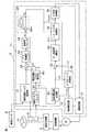
図1は、この発明の一実施形態に係るモータ制御装置を適用した電動パワーステアリング装置(車両用操舵装置の一例)の電気的構成を説明するためのブロック図である。この電動パワーステアリング装置は、車両を操向するための操作部材としてのステアリングホイール10に加えられる操舵トルクTを検出するトルクセンサ1と、車両の舵取り機構2に減速機構7を介して操舵補助力を与えるモータ3(ブラシレスモータ)と、ステアリングホイール10の回転角である操舵角を検出する舵角センサ4と、モータ3を駆動制御するモータ制御装置5と、当該電動パワーステアリング装置が搭載された車両の速度を検出する車速センサ6とを備えている。舵角センサ4は、ステアリングホイール10の中立位置(基準位置)からのステアリングホイール10の正逆両方向の回転量(回転角)を検出するものであり、中立位置から右方向への回転量を正の値として出力し、中立位置から左方向への回転量を負の値として出力する。Hereinafter, embodiments of the present invention will be described in detail with reference to the accompanying drawings.
FIG. 1 is a block diagram for explaining an electrical configuration of an electric power steering device (an example of a vehicle steering device) to which a motor control device according to an embodiment of the present invention is applied. This electric power steering apparatus includes a
モータ制御装置5は、トルクセンサ1が検出する操舵トルク、舵角センサ4が検出する操舵角および車速センサ6が検出する車速に応じてモータ3を駆動することによって、操舵状況および車速に応じた適切な操舵補助を実現する。
モータ3は、この実施形態では、三相ブラシレスモータであり、図2に図解的に示すように、界磁としてのロータ50と、このロータ50に対向するステータ55に配置されたU相、V相およびW相のステータ巻線51,52,53とを備えている。モータ3は、ロータの外部にステータを対向配置したインナーロータ型のものであってもよいし、筒状のロータの内部にステータを対向配置したアウターロータ型のものであってもよい。The motor control device 5 drives the
In this embodiment, the
各相のステータ巻線51,52,53の方向にU軸、V軸およびW軸をとった三相固定座標(UVW座標系)が定義される。また、ロータ50の磁極方向にd軸(磁極軸)をとり、ロータ50の回転平面内においてd軸と直角な方向にq軸(トルク軸)をとった二相回転座標系(dq座標系。実回転座標系)が定義される。dq座標系は、ロータ50とともに回転する回転座標系である。dq座標系では、q軸電流のみがロータ50のトルク発生に寄与するので、d軸電流を零とし、q軸電流を所望のトルクに応じて制御すればよい。ロータ50の回転角(ロータ角)θMは、U軸に対するd軸の回転角である。dq座標系は、ロータ角θMに従う実回転座標系である。このロータ角θMを用いることによって、UVW座標系とdq座標系との間での座標変換を行うことができる。Three-phase fixed coordinates (UVW coordinate system) are defined in which the U, V, and W axes are taken in the direction of the
一方、この実施形態では、制御上の回転角を表す制御角θCが導入される。制御角θCは、U軸に対する仮想的な回転角である。この制御角θCに対応する仮想的な軸をγ軸とし、このγ軸に対して90°進んだ軸をδ軸として、仮想二相回転座標系(γδ座標系。仮想回転座標系)を定義する。制御角θCがロータ角θMに等しいとき、仮想回転座標系であるγδ座標系と実回転座標系であるdq座標系とが一致する。すなわち、仮想軸としてのγ軸は実軸としてのd軸と一致し、仮想軸としてのδ軸は実軸としてのq軸と一致する。γδ座標系は、制御角θCに従う仮想回転座標系である。UVW座標系とγδ座標系との座標変換は、制御角θCを用いて行うことができる。On the other hand, in this embodiment, a control angle θC representing a control rotation angle is introduced. The control angle θC is a virtual rotation angle with respect to the U axis. A virtual axis corresponding to the control angle θC is a γ axis, and an axis advanced by 90 ° with respect to the γ axis is a δ axis, and a virtual two-phase rotational coordinate system (γδ coordinate system, virtual rotational coordinate system) is defined. Define. When the control angle θC is equal to the rotor angle θM , the γδ coordinate system, which is a virtual rotation coordinate system, matches the dq coordinate system, which is an actual rotation coordinate system. That is, the γ-axis as the virtual axis matches the d-axis as the real axis, and the δ-axis as the virtual axis matches the q-axis as the real axis. γδ coordinate system is an imaginary rotating coordinate system that rotates in accordance with the control angle thetaC. Coordinate conversion between the UVW coordinate system and the γδ coordinate system can be performed using the control angle θC.
制御角θCとロータ角θMとの差を負荷角θL(=θC−θM)と定義する。
制御角θCに従ってγ軸電流Iγをモータ3に供給すると、このγ軸電流Iγのq軸成分(q軸への正射影)がロータ50のトルク発生に寄与するq軸電流Iqとなる。すなわち、γ軸電流Iγとq軸電流Iqとの間に、次式(1)の関係が成立する。
Iq=Iγ・sinθL …(1)
再び図1を参照する。モータ制御装置5は、マイクロコンピュータ11と、このマイクロコンピュータ11によって制御され、モータ3に電力を供給する駆動回路(インバータ回路)12と、モータ3の各相のステータ巻線に流れる電流を検出する電流検出部13とを備えている。A difference between the control angle θC and the rotor angle θM is defined as a load angle θL (= θC −θM ).
When the γ-axis current Iγ is supplied to the
Iq = Iγ · sin θL (1)
Refer to FIG. 1 again. The motor control device 5 detects a current flowing in a
電流検出部13は、モータ3の各相のステータ巻線51,52,53に流れる相電流IU,IV,IW(以下、総称するときには「三相検出電流IUVW」という。)を検出する。これらは、UVW座標系における各座標軸方向の電流値である。
マイクロコンピュータ11は、CPUおよびメモリ(ROMおよびRAMなど)を備えており、所定のプログラムを実行することによって、複数の機能処理部として機能するようになっている。この複数の機能処理部には、操舵トルクリミッタ20と、指示操舵トルク設定部21と、トルク偏差演算部22と、PI(比例積分)制御部23と、加算角リミッタ24と、制御角演算部26と、指示電流値生成部30と、電流偏差演算部32と、PI制御部33と、γδ/UVW変換部34と、PWM(Pulse Width Modulation)制御部35と、UVW/γδ変換部36と、検出操舵トルク補正部40とが含まれている。The
The
指示操舵トルク設定部21は、舵角センサ4によって検出される操舵角と、車速センサ6によって検出される車速とに基づいて、指示操舵トルクT*を設定する。たとえば、図4に示すように、操舵角が正の値(右方向へ操舵した状態)のとき指示操舵トルクT*は正の値(右方向へのトルク)に設定され、操舵角が負の値(左方向へ操舵した状態)のとき指示操舵トルクT*は負の値(左方向へのトルク)に設定される。そして、操舵角の絶対値が大きくなるに従って、その絶対値が大きくなるように(図4の例では非線型に大きくなるように)指示操舵トルクT*が設定される。ただし、所定の上限値(正の値。たとえば、+6Nm)および下限値(負の値。たとえば−6Nm)の範囲内で指示操舵トルクT*の設定が行われる。また、指示操舵トルクT*は、車速が大きいほど、その絶対値が小さくなるように設定される。すなわち、車速感応制御が行われる。The command steering
操舵トルクリミッタ20は、トルクセンサ1の出力を所定の上限飽和値+Tmax(+Tmax>0。たとえば+Tmax=7Nm)と下限飽和値−Tmax(−Tmax<0。たとえば−Tmax=−7Nm)との間に制限する。具体的には、操舵トルクリミッタ20は、図5に示すように、上限飽和値+Tmaxと下限飽和値−Tmaxの間では、トルクセンサ1の検出操舵トルクTをそのまま出力する。また、操舵トルクリミッタ20は、トルクセンサ1の検出操舵トルクTが上限飽和値+Tmax以上であれば、上限飽和値+Tmaxを出力する。そして、操舵トルクリミッタ20は、トルクセンサ1の検出操舵トルクTが下限飽和値−Tmax以下であれば、下限飽和値−Tmaxを出力する。飽和値+Tmaxおよび−Tmaxは、トルクセンサ1の出力信号が安定な領域(信頼性のある領域)の境界を画定するものである。つまり、トルクセンサ1の出力信号は、上限飽和値Tmaxを超える区間、および下限飽和値−Tmaxを下回る区間では不安定であり、実際の操舵トルクに対応しなくなる。換言すれば、飽和値+Tmax,−Tmaxは、トルクセンサ1の出力特性に応じて定められる。トルクセンサ1によって検出され、操舵トルクリミッタ20による制限処理を受けた操舵トルクを、「検出操舵トルクTL」ということにする。The
検出操舵トルク補正部40は、操舵トルクリミッタ20によって得られる検出操舵トルクTLに基づいて、制御用検出操舵トルクを演算する制御用トルク演算手段である。言い換えれば、検出操舵トルク補正部40は、検出操舵トルクTLを補正することによって、制御用検出操舵トルク(以下、単に「検出操舵トルクT」という)を生成する。具体的には、検出操舵トルク補正部40は、図6に示すように、検出操舵トルクTLの絶対値|TL|が所定値a(a>0)以下であるとき(|TL|≦a)には、検出操舵トルクを0に補正する。そして、検出操舵トルク補正部40は、検出操舵トルクTLの絶対値|TL|が所定値aより大きいとき(|TL|>a)には、検出操舵トルクTLをそのまま出力する。所定値aは、たとえば、0.3〜0.5[Nm]の範囲内の値に設定される。検出操舵トルク補正部40による補正後の検出操舵トルクTは次式(2)で表される。The detected steering
if |TL|≦a, then T=0,
if |TL|>a, then T=TL …(2)
トルク偏差演算部22は、指示操舵トルク設定部21によって設定される指示操舵トルクT*と、トルクセンサ1によって検出され、操舵トルクリミッタ20による制限処理および検出操舵トルク補正部40による補正処理を受けた検出操舵トルクTとの偏差(トルク偏差)ΔT(=T*−T)を求める。PI制御部23は、このトルク偏差ΔTに対するPI演算を行う。すなわち、トルク偏差演算部22およびPI制御部23によって、検出操舵トルクTを指示操舵トルクT*に導くためのトルクフィードバック制御手段が構成されている。PI制御部23は、トルク偏差ΔTに対するPI演算を行うことで、制御角θCに対する加算角αを演算する。したがって、前記トルクフィードバック制御手段は、加算角αを演算する加算角演算手段を構成している。if | TL | ≦ a, then T = 0,
if | TL |> a, then T = TL (2)
The torque
加算角リミッタ24は、PI制御部23によって求められた加算角αに対して制限を加える。より具体的には、加算角リミッタ24は、所定の上限値UL(正の値)と下限値LL(負の値)との間の値に加算角αを制限する。上限値ULおよび下限値LLは、所定の制限値ωmax(ωmax>0。たとえばωmaxの既定値=45度)に基づいて定められる。この所定の制限値ωmaxの既定値は、たとえば、最大操舵角速度に基づいて定められる。最大操舵角速度とは、ステアリングホイール10の操舵角速度として想定され得る最大値であり、たとえば、800deg/sec程度である。The
最大操舵角速度のときのロータ50の電気角の変化速度(電気角での角速度。最大ロータ角速度)は、次式(3)のとおり、最大操舵角速度と、減速機構7の減速比と、ロータ50の極対数との積で与えられる。極対数とは、ロータ50が有する磁極対(N極とS極との対)の個数である。
最大ロータ角速度=最大操舵角速度×減速比×極対数 …(3)
制御角θCの演算間(演算周期)におけるロータ50の電気角変化量の最大値(ロータ角変化量最大値)は、次式(4)のとおり、最大ロータ角速度に演算周期を乗じた値となる。The change speed of the electrical angle of the
Maximum rotor angular speed = Maximum steering angular speed x Reduction ratio x Number of pole pairs (3)
The maximum value of the electrical angle change amount of the rotor 50 (the maximum value of the rotor angle change amount) during the calculation (control cycle) of the control angle θC is a value obtained by multiplying the maximum rotor angular velocity by the calculation cycle as shown in the following equation (4). It becomes.
ロータ角変化量最大値=最大ロータ角速度×演算周期
=最大操舵角速度×減速比×極対数×演算周期 …(4)
このロータ角変化量最大値が一演算周期間で許容される制御角θCの最大変化量である。そこで、前記ロータ角変化量最大値を制限値ωmaxの既定値とすればよい。この制限値ωmaxを用いて、加算角αの上限値ULおよび下限値LLは、それぞれ次式(5)(6)で表すことができる。Maximum value of rotor angle change = Maximum rotor angular speed x Calculation cycle
= Maximum steering angular velocity x reduction ratio x number of pole pairs x calculation cycle (4)
The rotor angle variation maximum value is the maximum variation of the control angle thetaC that is permitted within one calculation cycle. Therefore, the maximum value of the rotor angle change may be set as a predetermined value of the limit value ωmax . Using the limit value ωmax , the upper limit value UL and the lower limit value LL of the addition angle α can be expressed by the following equations (5) and (6), respectively.
UL=+ωmax …(5)
LL=−ωmax …(6)
加算角リミッタ24による制限処理後の加算角αが、制御角演算部26の加算器26Aにおいて、制御角θCの前回値θC(n-1)(nは今演算周期の番号)に加算される(Z−1は信号の前回値を表す)。ただし、制御角θCの初期値は予め定められた値(たとえば零)である。UL = + ωmax (5)
LL = −ωmax (6)
The addition angle α after the limit processing by the
制御角演算部26は、制御角θCの前回値θC(n-1)に加算角リミッタ24から与えられる加算角αを加算する加算器26Aを含む。すなわち、制御角演算部26は、所定の演算周期毎に制御角θCを演算する。そして、前演算周期における制御角θCを前回値θC(n-1)とし、これを用いて今演算周期における制御角θCである今回値θC(n)を求める。
指示電流値生成部30は、制御上の回転角である前記制御角θCに対応する仮想回転座標系であるγδ座標系の座標軸(仮想軸)に流すべき電流値を指示電流値として生成するものである。具体的には、γ軸指示電流値Iγ*およびδ軸指示電流値Iδ*(以下、これらを総称するときには「二相指示電流値Iγδ*」という。)を生成する。指示電流値生成部30は、γ軸指示電流値Iγ*を有意値とする一方で、δ軸指示電流値Iδ*を零とする。より具体的には、指示電流値生成部30は、トルクセンサ1によって検出され、操舵トルクリミッタ20による制限処理を受けた検出操舵トルクTLに基づいてγ軸指示電流値Iγ*を設定する。The control
The command current
検出操舵トルクTLに対するγ軸指示電流値Iγ*の設定例は、図7に示されている。検出操舵トルクTLが零付近の範囲Lでは、γ軸指示電流値Iγ*は小さい値に設定される。そして、γ軸指示電流値Iγ*は、検出操舵トルクTLが零付近の範囲Lの外側の領域で急峻に立ち上がり、所定のトルク以上でほぼ一定値となるように設定される。これにより、運転者がステアリングホイール10を操作していないときには、γ軸指示電流値Iγ*が低減され、不必要な電力消費が抑制される。A setting example of the γ-axis command current value Iγ* with respect to the detected steering torqueTL is shown in FIG. In the rangeL where the detected steering torqueTL is near zero, the γ-axis command current value Iγ* is set to a small value. The γ-axis command current value Iγ* is set so that the detected steering torqueTL rises steeply in a region outside the range L near zero and becomes a substantially constant value above a predetermined torque. Thus, when the driver is not operating the
電流偏差演算部32は、指示電流値生成部30によって生成されたγ軸指示電流値Iγ*に対するγ軸検出電流Iγの偏差Iγ*−Iγと、δ軸指示電流値Iδ*(=0)に対するδ軸検出電流Iδの偏差Iδ*−Iδとを演算する。γ軸検出電流Iγおよびδ軸検出電流Iδは、UVW/γδ変換部36から偏差演算部32に与えられるようになっている。The current
UVW/γδ変換部36は、電流検出部13によって検出されるUVW座標系の三相検出電流IUVW(U相検出電流IU、V相検出電流IVおよびW相検出電流IW)をγδ座標系の二相検出電流IγおよびIδ(以下総称するときには「二相検出電流Iγδ」という。)に変換する。これらが電流偏差演算部32に与えられるようになっている。UVW/γδ変換部36における座標変換には、制御角演算部26で演算される制御角θCが用いられる。The UVW /
PI制御部33は、電流偏差演算部32によって演算された電流偏差に対するPI演算を行うことにより、モータ3に印加すべき二相指示電圧Vγδ*(γ軸指示電圧Vγ*およびδ軸指示電圧Vδ*)を生成する。この二相指示電圧Vγδ*が、γδ/UVW変換部34に与えられる。
γδ/UVW変換部34は、二相指示電圧Vγδ*に対して座標変換演算を行うことによって、三相指示電圧VUVW*を生成する。三相指示電圧VUVW*は、U相指示電圧VU*、V相指示電圧VV*およびW相指示電圧VW*からなる。この三相指示電圧VUVW*は、PWM制御部35に与えられる。The
The γδ /
PWM制御部35は、U相指示電圧VU*、V相指示電圧VV*およびW相指示電圧VW*にそれぞれ対応するデューティのU相PWM制御信号、V相PWM制御信号およびW相PWM制御信号を生成し、駆動回路12に供給する。
駆動回路12は、U相、V相およびW相に対応した三相インバータ回路からなる。このインバータ回路を構成するパワー素子がPWM制御部35から与えられるPWM制御信号によって制御されることにより、三相指示電圧VUVW*に相当する電圧がモータ3の各相のステータ巻線51,52、53に印加されることになる。The
The
電流偏差演算部32およびPI制御部33は、電流フィードバック制御手段を構成している。この電流フィードバック制御手段の働きによって、モータ3に流れるモータ電流が、指示電流値生成部30によって設定された二相指示電流値Iγδ*に近づくように制御される。
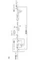
図3は、前記電動パワーステアリング装置の制御ブロック図である。ただし、説明を簡単にするために、加算角リミッタ24の機能は省略してある。The current
FIG. 3 is a control block diagram of the electric power steering apparatus. However, for the sake of simplicity, the function of the
指示操舵トルクT*と検出操舵トルクTとの偏差(トルク偏差)ΔTに対するPI制御(KPは比例係数、KIは積分係数、1/sは積分演算子である。)によって、加算角αが生成される。この加算角αが制御角θCの前回値θC(n-1)に対して加算されることによって、制御角θCの今回値θC(n)=θC(n-1)+αが求められる。このとき、制御角θCとロータ50の実際のロータ角θMとの偏差が負荷角θL=θC−θMとなる。Command steering torque T* and the deviation (torque deviation) of the detected steering torque T PI control for the [Delta] T (KP is a proportionality coefficient, KI is an integration coefficient, 1 / s is an integration operator.) By the addition angle α Is generated. It is obtained by adding the addition the addition angle alpha control angle theta previous value ofC θ C (n-1) , the current value of the control angleθ C θ C (n) = θ C (n-1) + α is Desired. At this time, the deviation between the control angle θC and the actual rotor angle θM of the
したがって、制御角θCに従うγδ座標系(仮想回転座標系)のγ軸(仮想軸)にγ軸指示電流値Iγ*に従ってγ軸電流Iγが供給されると、q軸電流Iq=IγsinθLとなる。このq軸電流Iqがロータ50の発生トルクに寄与する。すなわち、モータ3のトルク定数KTをq軸電流Iq(=IγsinθL)に乗じた値が、アシストトルクTA(=KT・IγsinθL)として、減速機構7を介して、舵取り機構2に伝達される。このアシストトルクTAを舵取り機構2からの負荷トルクTLから減じた値が、運転者がステアリングホイール10に与えるべき操舵トルクTである。この操舵トルクTがフィードバックされることによって、この操舵トルクTを指示操舵トルクT*に導くように系が動作する。つまり、検出操舵トルクTを指示操舵トルクT*に一致させるべく、加算角αが求められ、それに応じて制御角θCが制御される。Accordingly, when the γ-axis current Iγ is supplied according to the γ-axis command current value Iγ* to the γ-axis (virtual axis) of the γδ coordinate system (virtual rotation coordinate system) according to the control angle θC , the q-axis current Iq = Iγ sinθL This q-axis current Iq contributes to the torque generated by the
このように制御上の仮想軸であるγ軸に電流を流す一方で、指示操舵トルクT*と検出操舵トルクTとの偏差ΔTに応じて求められる加算角αで制御角θCを更新していくことにより、負荷角θLが変化し、この負荷角θLに応じたトルクがモータ3から発生するようになっている。これにより、操舵角および車速に基づいて設定される指示操舵トルクT*に応じたトルクをモータ3から発生させることができるので、操舵角および車速に対応した適切な操舵補助力を舵取り機構2に与えることができる。すなわち、操舵角の絶対値が大きいほど操舵トルクが大きく、かつ、車速が大きいほど操舵トルクが小さくなるように、操舵補助制御が実行される。In this way, while a current is passed through the γ axis, which is a virtual axis for control, the control angle θC is updated with the addition angle α obtained according to the deviation ΔT between the command steering torque T* and the detected steering torque T. by going, the load angle thetaL is changed, the torque corresponding to the load angle thetaL is adapted to generate from the
このようにして、回転角センサを用いることなくモータ3を適切に制御して、適切な操舵補助を行うことができる電動パワーステアリング装置を実現できる。これにより、構成を簡単にすることができ、コストの削減を図ることができる。
図8は、加算角リミッタ24の働きを説明するためのフローチャートである。加算角リミッタ24は、PI制御部23によって求められた加算角αを上限値ULと比較し(ステップS1)、加算角αが上限値ULを超えている場合(ステップS1:YES)には、上限値ULを加算角αに代入する(ステップS2)。したがって、制御角θCに対して上限値UL(=+ωmax)が加算されることになる。In this way, an electric power steering apparatus that can appropriately control the
FIG. 8 is a flowchart for explaining the operation of the
PI制御部23によって求められた加算角αが上限値UL以下であれば(ステップS1:NO)、加算角リミッタ24は、さらに、その加算角αを下限値LLと比較する(ステップS3)。そして、その加算角αが下限値未満であれば(ステップS3:YES)、下限値LLを加算角αに代入する(ステップS4)。したがって、制御角θCに対して下限値LL(=−ωmax)が加算されることになる。If the addition angle α obtained by the
PI制御部23によって求められた加算角αが下限値LL以上上限値UL以下(ステップS3:NO)であれば、その加算角αがそのまま制御角θCへの加算のために用いられる。
このようにして、加算角αを上限値ULと下限値LLとの間に制限することができるので、制御の安定化を図ることができる。より具体的には、電流不足時や制御開始時に制御不安定状態(アシスト力が不安定な状態)が発生しても、この状態から安定な制御状態への遷移を促すことができる。The addition angle α obtained or lower than the lower limit LL or the upper limit UL by the PI control unit 23: if (step S3 NO), the addition angle α is used as is added to the control angle thetaC.
In this way, the addition angle α can be limited between the upper limit value UL and the lower limit value LL, so that the control can be stabilized. More specifically, even if a control unstable state (a state where the assist force is unstable) occurs when the current is insufficient or the control is started, the transition from this state to the stable control state can be promoted.
前記実施形態では、検出操舵トルク補正部40が備えられている。検出操舵トルク補正部40は、検出操舵トルクTLの絶対値|TL|が所定値a以下であるとき(|TL|≦a)には、検出操舵トルクを0に補正し、検出操舵トルクTLの絶対値|TL|が所定値aより大きいとき(|TL|>a)には、検出操舵トルクTLをそのまま出力する。
このような検出操舵トルク補正部40が備えられていない場合には、次のような問題が発生するおそれがある。ステアリングホイール10が中立位置にある場合には、舵角センサ4によって検出される検出操舵角が0となるため、指示操舵トルク設定部21によって設定される指示操舵トルクT*は、図4に示すように、0[Nm]となる。一方、ステアリングホイール10の中立位置付近でステアリングホイール10から運転者が手を放すと、トルクセンサ1によって検出される操舵トルクに誤差が含まれていると、トルクセンサ1によって検出される操舵トルクは0[Nm]にならない。したがって、トルク偏差演算部22によって演算されるトルク偏差ΔTが0にならないから、制御角θCが変動する。そうすると、モータ3のトルク(アシストトルク)が変化するので、舵取り機構2に操舵力が与えられる。In the embodiment, the detected steering
If such a detected steering
つまり、検出操舵トルク補正部40が備えられていない場合には、ステアリングホイール10をその中立位置付近で手放し状態にすると、舵取り機構2によって舵取り車輪が転舵する、セルフステアが生じるおそれがある。
前記実施形態では、ステアリングホイール10をその中立位置付近で手放し状態にした場合、トルクセンサ1によって検出される検出操舵トルクは0[Nm]にならなくても、検出操舵トルク補正部40によって、トルクセンサ1によって検出された検出操舵トルクが0[Nm]に補正される。これにより、トルク偏差演算部22によって演算されるトルク偏差ΔTが0となるから、制御角θCが変化しなくなる。したがって、この実施形態によれば、ステアリングホイール10をその中立位置付近で手放し状態にした場合に、セルフステアが生じることを防止できる。That is, when the detected steering
In the above-described embodiment, when the
前記検出操舵トルク補正部40では、図6に示すように、トルクリミッタ20から出力される検出操舵トルクTLが、所定値aまたは所定値−aを跨いで変化するときには、検出操舵トルク補正部40から出力される検出操舵トルクTが急峻に変化する。そうすると、操舵トルクも急峻に変動するので、操舵感が悪化するおそれがある。
そこで、検出操舵トルク補正部40として、図9に示すような、入出力特性を有するものを用いるようにしてもよい。具体的には、この検出操舵トルク補正部40は、検出操舵トルクTLの絶対値|TL|が第1の所定値a(a>0)以下であるとき(|TL|≦a)には、検出操舵トルクTLを0に補正する。また、検出操舵トルク補正部40は、検出操舵トルクTLが第1の所定値aより大きくかつ第1の所定値aより大きな第2の所定値b(b>0)より小さいときには(a<TL<b)には、検出操舵トルクTLが所定値aより大きくなるにしたがって、その出力値Tが零付近から滑らかに大きくなるように(図9の例では線型に変化するように)、検出操舵トルクTLを補正する。また、検出操舵トルク補正部40は、検出操舵トルクTLが第2の所定値b以上の場合には、検出操舵トルクTLをそのまま出力する。As shown in FIG. 6, when the detected steering torqueTL output from the
Therefore, a detection steering
また、検出操舵トルク補正部40は、検出操舵トルクTLが所定値−aより小さくかつ所定値−bより大きいときには(−b<TL<−a)には、検出操舵トルクTLが所定値−aより小さくなるにしたがって、その出力値Tが零付近から滑らかに小さくなるように(図9の例では線型に変化するように)、検出操舵トルクTLを補正する。また、検出操舵トルク補正部40は、検出操舵トルクTLが所定値−b以下の場合には、検出操舵トルクTLをそのまま出力する。Further, the detected steering
第1の所定値aは、たとえば、0.3〜0.5[Nm]の範囲内の値に設定される。第2の所定値bは、たとえば、トルクセンサ1が検出可能な最大トルク(トルクセンサ1の出力が飽和する直前の最大トルク)と同じ値またはそれより小さな値に設定される。より具体的には、第2の所定値bは、前述した上限飽和値+Tmax(図5参照)と同じ値またはそれより小さな値に設定されてもよい。The first predetermined value a is set to a value within the range of 0.3 to 0.5 [Nm], for example. For example, the second predetermined value b is set to a value equal to or smaller than the maximum torque that can be detected by the torque sensor 1 (the maximum torque immediately before the output of the
つまり、検出操舵トルク補正部40は、次式(7-1)〜(7-5)に基づいて、検出操舵トルクTを演算する。ただし、第2の所定値bを上限飽和値に等しく定めたときには、式(7-3)および(7-5)による補正は、不要となる。
if −a≦TL≦a, then T=0 …(7-1)
if a<TL<b, then T={b/(b−a)}・TL−{ab/(b−a)}…(7-2)
if TL≧b, then T=TL…(7-3)
if −b<TL<−a, then T={b/(b−a)}・TL+{ab/(b−a)}…(7-4)
if TL≦−b, then T=TL…(7-5)
具体的には、前記式(7-1)〜(7-5)に基づいて、図9に示すような入出力特性に対応するマップが予め作成されており、検出操舵トルク補正部40は、このマップに基づいて、検出操舵トルクを補正する。このような検出操舵トルク補正部40を用いた場合には、トルクリミッタ20から出力される検出操舵トルクTLが、所定値aまたは所定値−aを跨いで変化したときでも、検出操舵トルク補正部40によって演算される検出操舵トルクTは滑らかに変化するので、操舵感が向上する。That is, the detected steering
if −a ≦ TL ≦ a, then T = 0 (7-1)
if a <TL <b, then T = {b / (b−a)} · TL − {ab / (b−a)} (7-2)
if TL ≧ b, then T = TL (7-3)
if -b <TL <-a, then T = {b / (ba)}.TL + {ab / (ba)} (7-4)
if TL ≦ −b, then T = TL (7-5)
Specifically, a map corresponding to the input / output characteristics as shown in FIG. 9 is created in advance based on the equations (7-1) to (7-5), and the detected steering
なお、図9の例では、検出操舵トルクTLが第1の所定値aより大きくかつ第2の所定値bより小さいとき(a<TL<b)または検出操舵トルクTLが所定値−aより小さくかつ所定値−bより大きいとき(−b<TL<−a)には、検出操舵トルク補正部40の入出力特性は、検出操舵トルクTLの絶対値が大きくなるにしたがって、その出力値Tの絶対値が零付近から線型に滑らかに大きくなるように変化しているが、零付近から非線型に滑らかに大きくなるように変化するような特性であってもよい。In the example of FIG. 9, when the detected steering torqueTL is larger than the first predetermined value a and smaller than the second predetermined value b (a <TL <b), or the detected steering torqueTL is a predetermined value −. When the value is smaller than a and larger than the predetermined value −b (−b <TL <−a), the input / output characteristics of the detected steering
以上、この発明の一実施形態について説明したが、この発明はさらに他の形態で実施することもできる。たとえば、前述の実施形態では、PI制御部23によって加算角αを求めているが、PI制御部23に代えて、PID(比例・積分・微分)演算部を用いて加算角αを求める構成とすることもできる。
また、前述の実施形態では、回転角センサを備えずに、専らセンサレス制御によってモータ3を駆動する構成について説明したが、レゾルバ等の回転角センサを備え、この回転角センサの故障時に前述のようなセンサレス制御を行う構成としてもよい。これにより、回転角センサの故障時にもモータ3の駆動を継続できるから、操舵補助を継続できる。As mentioned above, although one Embodiment of this invention was described, this invention can also be implemented with another form. For example, in the above-described embodiment, the addition angle α is obtained by the
In the above-described embodiment, the configuration in which the
この場合、回転角センサを用いるときには、指示電流値生成部30において、操舵トルクおよび車速に応じて、所定のアシスト特性に従ってδ軸指示電流値Iδ*を発生させるようにすればよい。
さらに、前述の実施形態では、電動パワーステアリング装置にこの発明が適用された例について説明したが、この発明は、電動ポンプ式油圧パワーステアリング装置のためのモータの制御や、パワーステアリング装置以外にも、ステア・バイ・ワイヤ(SBW)システム、可変ギヤレシオ(VGR)ステアリングシステムその他の車両用操舵装置に備えられたブラシレスモータの制御のために用いることができる。むろん、車両用操舵装置に限らず、他の用途のモータの制御のためにも本発明のモータ制御装置を適用できる。In this case, when the rotation angle sensor is used, the command current
Further, in the above-described embodiment, the example in which the present invention is applied to the electric power steering apparatus has been described. However, the present invention is not limited to the motor control for the electric pump type hydraulic power steering apparatus or the power steering apparatus. It can be used for control of a brushless motor provided in a steer-by-wire (SBW) system, a variable gear ratio (VGR) steering system and other vehicle steering devices. Of course, the motor control device of the present invention can be applied not only to the vehicle steering device but also to control a motor for other purposes.
その他、特許請求の範囲に記載された事項の範囲で種々の設計変更を施すことが可能である。
この明細書からはさらに以下のような特徴が抽出され得る。なお、括弧内の英数字は前述の実施形態等における対応構成要素等を示す。
1.ロータ(50)と、このロータに対向するステータ(55)とを備えたモータ(3)を制御するためのモータ制御装置(5)であって、制御上の回転角である制御角(θC)に従う回転座標系の軸電流値(Iγ*)で前記モータを駆動する電流駆動手段(30,32〜36)と、前記制御角に加算すべき加算角を演算する加算角演算手段(22,23)と、所定の演算周期毎に、前記加算角演算手段によって演算された加算角を制御角の前回値に加算することによって、制御角の今回値を求める制御角演算手段(26)と、前記モータによって駆動される駆動対象(2)に加えられる、モータトルク以外のトルク(TL)に基づいて制御用トルク(T)を演算する制御用トルク演算手段(40)と、前記駆動対象に作用されるべき指示トルク(T*:モータトルク以外のトルクの指示値)を設定する指示トルク設定手段(21)とを含み、前記加算角演算手段は、前記指示トルク設定手段によって設定される指示トルクと、前記制御用トルク演算手段によって演算される制御用トルクとの偏差に基づいて、加算角を演算するものである、モータ制御装置。
この構成によれば、制御角に従う回転座標系(γδ座標系。以下「仮想回転座標系」といい、この仮想回転座標系の座標軸を「仮想軸」という。)の軸電流値(以下「仮想軸電流値」という。)によってモータが駆動される一方で、制御角は、演算周期毎に加算角を加算することによって更新される。これにより、制御角を更新しながら、すなわち、仮想回転座標系の座標軸(仮想軸)を更新しながら、仮想軸電流値でモータを駆動することによって、必要なトルクを発生させることができる。こうして、回転角センサを用いることなく、モータから適切なトルクを発生させることができる。
さらに、この構成では、駆動対象に加えられる、モータトルク以外のトルクに基づいて、制御用トルクが制御用トルク演算手段によって演算される。また、駆動対象に作用されるべき指示トルクが、指示トルク設定手段によって設定される。そして、加算角演算手段は、指示トルク設定手段によって設定される指示トルクと、制御用トルク演算手段によって演算される制御用トルクとの偏差に基づいて、加算角を演算する。
加算角演算手段は、たとえば、制御用トルクを指示トルクに一致させるべく、加算角を演算するように動作する。これにより、指示トルクに応じたトルク(モータトルク以外のトルク)が駆動対象に加えられる状態となるように、モータトルクが制御(フィードバック制御)される。モータトルクは、ロータの磁極方向に従う回転座標系(dq座標系)の座標軸と前記仮想軸とのずれ量である負荷角に対応する。負荷角は、制御角とロータ角との差で表される。モータトルクの制御は、負荷角を調整することによって達成され、この負荷角の調整が加算角を制御することによって達成される。
この構成によれば、制御用トルク演算手段は、モータトルク以外のトルクに基づいて制御用トルクを演算する。この演算された制御用トルクが、モータの制御のために用いられる。したがって、モータトルク以外のトルクが加算角演算のためにそのまま用いられると、モータトルクの制御上、何らかの不都合が生じるような場合に、加算角演算のために用いられる制御用トルクを、モータトルク以外のトルクとは異なる値に設定することができる。これにより、前記不都合を回避または抑制することが可能となる。
2.前記制御用トルク演算手段に入力される前記モータトルク以外のトルクをTL、第1の所定値をa(a>0)、前記第1の所定値aより大きな第2の所定値をb(b>0)とすると、前記制御用トルク演算手段は、次式(A)に基づいて、制御用トルクTを演算するものである、前記1.に記載のモータ制御装置。
−a≦TL≦aのときT=0,
a<TL<bのときT={b/(b−a)}・TL−{ab/(b−a)},
−b<TL<−aのときT={b/(b−a)}・TL+{ab/(b−a)}…(A)
この構成では、モータトルク以外のトルクTLが所定値−a以上でかつ所定値a以下であるときには、制御用トルク演算手段によって演算される制御用トルクTは零となる。また、モータトルク以外のトルクTLが所定値aより大きくかつ所定値bより小さいときには、制御用トルク演算手段によって演算される制御用トルクTは、モータトルク以外のトルクTLが所定値aから大きくなるにしたがって、零付近から滑らかに(線型に)大きくなる。
また、モータトルク以外のトルクTLが所定値−bより大きくかつ所定値−aより小さいときには、制御用トルク演算手段によって演算される制御用トルクTは、モータトルク以外のトルクTLが所定値−aから小さくなるにしたがって、零付近から滑らかに(線型に)小さくなる。
この構成によれば、モータトルク以外のトルクTLが所定値−a以上でかつ所定値a以下の範囲内にある場合に、加算角の演算に用いられる制御用トルクを零に設定することができる。したがって、モータトルク以外のトルクTLが、所定値−a以上でかつ所定値a以下の範囲内において変動することにより、モータトルクの制御上、何らかの不都合が発生するような場合には、そのような不都合を回避または抑制することができるようになる。具体的には、モータトルク以外のトルクTLが誤差を含む場合に、TL=0付近で、当該誤差の影響がモータ制御に及ぶことを回避できる。
また、モータトルク以外のトルクTLが所定値aより大きくかつ所定値bより小さいときには、制御用トルクTは、トルクTLが所定値aより大きくなるにしたがって、零付近から滑らかに大きくなり、トルクTLが所定値−bより大きくかつ所定値−aより小さいときには、制御用トルクTは、トルクTLが所定値−aから小さくなるにしたがって、零付近から滑らかに小さくなる。したがって、モータトルク以外のトルクTLが所定値aまたは所定値−aを跨いで変化した場合でも、制御用トルクTが滑らかに変化するため、モータトルクを滑らかに変化させることができる。
3.前記制御用トルク演算手段は、前記モータトルク以外のトルクの絶対値が所定値以下の範囲内であるときには、制御用トルクを零に設定する手段を含む、前記1.に記載のモータ制御装置。この構成によれば、モータトルク以外のトルクの絶対値が所定値以下の範囲内にある場合に、加算角の演算に用いられる制御用トルクを零に設定することができる。したがって、モータトルク以外のトルクTLの絶対値が、所定値以下の範囲内において変動することにより、モータトルクの制御上、何らかの不都合が発生するような場合には、そのような不都合を回避または抑制することができるようになる。具体的には、モータトルク以外のトルクTLが誤差を含む場合に、TL=0付近で、当該誤差の影響がモータ制御に及ぶことを回避できる。
4.車両の舵取り機構(2)に駆動力を付与するモータ(3)と、前記モータを制御する前記1.〜前記3.のいずれかに記載のモータ制御装置とを含む、車両用操舵装置。この構成によれば、モータトルク以外のトルクが加算角演算のためにそのまま用いられると、モータトルクの制御上、何らかの不都合が生じるような場合に、このような不都合を回避または抑制することが可能となる車両用操舵装置が得られる。
前記モータ制御装置は、たとえば、前記モータトルク以外のトルクを検出するためのトルク検出手段(1)をさらに含み、前記制御用トルク演算手段は、前記トルク検出手段によって検出されるトルクに基づいて、制御用トルクを演算するものであってもよい。
前記モータは、車両の舵取り機構(2)に駆動力を付与するものであってもよい。この場合に、前記トルク検出手段は、前記車両の操向のために操作される操作部材(10)に加えられる操舵トルクを検出するものであってもよい。また、前記制御用トルク演算手段は、トルク検出手段によって検出される検出操舵トルクに基づいて、制御用検出操舵トルクを演算するものであってもよい。また、前記指示トルク設定手段は、操舵トルクの目標値としての指示操舵トルクを設定するものであってもよい。そして、前記加算角演算手段は、前記指示トルク設定手段によって設定される指示操舵トルクと前記制御用トルク演算手段によって演算される制御用検出操舵トルクとの偏差に応じて前記加算角を演算するものであってもよい。
この構成によれば、指示操舵トルクが設定され、この指示操舵トルクと制御用検出操舵トルクとの偏差に応じて前記加算角が演算される。これにより、制御用検出操舵トルクが当該指示操舵トルクとなるように加算角が定められ、それに応じた制御角が定められることになる。したがって、指示操舵トルクを適切に定めておくことによって、モータから適切な駆動力を発生させて、これを舵取り機構に付与することができる。すなわち、ロータの磁極方向に従う回転座標系(dq座標系)の座標軸と前記仮想軸とのずれ量(負荷角)が指示操舵トルクに応じた値に導かれる。その結果、適切なトルクがモータから発生され、運転者の操舵意図に応じた駆動力を舵取り機構に付与できる。
たとえば、前記2.または前記3.の特徴を採るとすれば、トルク検出手段が出力する検出トルクTLに誤差が含まれているときに、検出トルクTL=0の付近において、モータ制御に対する誤差の影響を排除できる。そのため、運転者の操舵意図に従う制御が可能となり、良好な操舵感が得られる。さらに、前記2.の特徴が採られるときには、制御トルクが不連続となることを回避できるから、一層すぐれた操舵感を実現できる。
前記モータ制御装置または前記車両用操舵装置は、前記操作部材の操舵角を検出する操舵角検出手段(4)をさらに含み、前記指示トルク設定手段は、前記操舵角検出手段によって検出される操舵角に応じて指示操舵トルクを設定するものであることが好ましい。この構成によれば、操作部材の操舵角に応じて指示操舵トルクが設定されるので、操舵角に応じた適切なトルクをモータから発生させることができ、運転者が操作部材に加える操舵トルクを操舵角に応じた値へと導くことができる。これにより、良好な操舵感を得ることができる。
この場合、前記指示トルク設定手段は、たとえば、前記操舵角検出手段によって検出される操舵角の絶対値が大きくなるにしたがって、指示操舵トルクの絶対値が大きくなるように、指示操舵トルクを設定するものであってもよい。この場合、さらに、前記指示トルク設定手段は、前記操舵角検出手段によって検出される操舵角が零のとき、すなわち、操作部材(たとえば、ステアリングホイール)が中立位置にあるときに、指示操舵トルクを零に設定するものであってもよい。
このような場合において、操作部材の中立位置付近で操作部材から運転者が手を放すと、実際の操舵トルクは零となるが、操舵トルク検出手段によって検出される検出操舵トルクに誤差があると、検出操舵トルクは零にならない。この誤差を含む検出操舵トルクがそのまま加算角を演算するために用いられたとすると、指示操舵トルクと検出操舵トルクとの偏差が零にならないため、制御角が変動し、モータトルク(アシストトルク)が変動する。その結果、操作部材をその中立位置付近で手放し状態にすると、意図しない操舵力が舵取り機構に与えられ、いわゆるセルフステアが生じるおそれがある。
そこで、たとえば、前記2.または前記3.のモータ制御装置のように、検出操舵トルクの絶対値が所定値以下の範囲内であるときには、前記制御用トルク演算手段によって、制御用検出操舵トルクを零に設定することにより、セルフステアを回避できる。すなわち、操作部材をその中立位置付近で手放し状態にした場合、検出操舵トルクは零にならなくても、制御用検出操舵トルクを零にすることができる。これにより、指示操舵トルクと制御用検出操舵トルクとの偏差が零になるから、制御角が変化しなくなる。これにより、セルフステアを防止できる。
前記指示トルク設定手段は、前記車両の車速を検出する車速検出手段(6)によって検出される当該車速に応じて指示操舵トルクを設定するものであってもよい。この構成によれば、車速に応じて指示操舵トルクが設定されるので、いわゆる車速感応制御を行うことができる。その結果、良好な操舵感を実現できる。たとえば、車速が大きいほど、すなわち、高速走行時ほど指示操舵トルクを小さく設定することより、すぐれた操舵感が得られる。In addition, various design changes can be made within the scope of matters described in the claims.
The following features can be further extracted from this specification. The alphanumeric characters in parentheses indicate the corresponding components in the above-described embodiment.
1. A motor control device (5) for controlling a motor (3) including a rotor (50) and a stator (55) facing the rotor, the control angle (θC) being a control rotation angle) According to the rotational coordinate system (Iγ*) of therotating coordinate system andcurrent drive means (30, 32-36) for driving the motor, and addition angle calculation means (22) for calculating the addition angle to be added to the control angle. , 23), and control angle calculation means (26) for obtaining the current value of the control angle by adding the addition angle calculated by the addition angle calculation means to the previous value of the control angle at every predetermined calculation cycle.A control torque calculating means (40) for calculating a control torque (T) based ona torque (TL)other than the motor torque applied to the drive target (2) driven by the motor;and the drive target Instructions to be acted uponClick:and a command torque setting means for setting a(T *instruction value of the torque other than the motor torque) (21), the addition angle calculation unit includes a command torque set by the command torque setting unit, the control A motor control device that calculates the addition angle based on a deviation from the control torque calculated by the torque calculation means.
According to this configuration, the axis current value (hereinafter “virtual axis”) of the rotating coordinate system (γδ coordinate system, hereinafter referred to as “virtual rotating coordinate system”, the coordinate axis of this virtual rotating coordinate system being referred to as “virtual axis”) according to the control angle. While the motor is driven by the "shaft current value"), the control angle is updated by adding the addition angle every calculation cycle. Thus, the necessary torque can be generated by driving the motor with the virtual axis current value while updating the control angle, that is, while updating the coordinate axis (virtual axis) of the virtual rotation coordinate system. Thus, an appropriate torque can be generated from the motor without using a rotation angle sensor.
Further, in this configuration, the control torque is calculated by the control torque calculation means based on torque other than the motor torque applied to the drive target. Further, the command torque to be applied to the drive target is set by the command torque setting means. The addition angle calculation means calculates the addition angle based on a deviation between the instruction torque set by the instruction torque setting means and the control torque calculated by the control torque calculation means.
The addition angle calculation means operates so as to calculate the addition angle, for example, so that the control torque matches the command torque. Thereby, the motor torque is controlled (feedback control) so that a torque (torque other than the motor torque) corresponding to the command torque is applied to the drive target. The motor torque corresponds to a load angle that is a deviation amount between the coordinate axis of the rotating coordinate system (dq coordinate system) according to the magnetic pole direction of the rotor and the virtual axis. The load angle is represented by the difference between the control angle and the rotor angle. Control of the motor torque is achieved by adjusting the load angle, and this adjustment of the load angle is achieved by controlling the addition angle.
According to this configuration, the control torque calculation means calculates the control torque based on torque other than the motor torque. The calculated control torque is used for controlling the motor. Therefore, if any torque other than the motor torque is used as it is for the addition angle calculation, the control torque used for the addition angle calculation other than the motor torque is used when there is some inconvenience in controlling the motor torque. The torque can be set to a different value. Thereby, it becomes possible to avoid or suppress the inconvenience.
2. Torque other than the motor torque input to the control torque calculation means is TL, the first predetermined value is a (a> 0), and the second predetermined value larger than the first predetermined value a is b ( b> 0), the control torque calculation means calculates the control torque T based on the following equation (A). The motor control device described in 1.
−0 ≦ TL≦ a, T = 0,
When a <TL<b, T = {b / (b−a)} · TL− {ab / (b−a)},
When -b <TL<-a, T = {b / (ba)}.TL+ {ab / (ba)} (A)
In this configuration, when the torqueTLother than the motor torque is notless than the predetermined value −a and not more than the predetermined value a, the control torque T calculated by the control torque calculating means is zero. Further, when the torqueTLother than the motor torqueis larger than the predetermined value a and smaller than the predetermined value b, the control torque T calculated by the control torque calculating means is such that the torqueTLother than the motor torque isfrom the predetermined value a. As it grows larger, it grows smoothly (linearly) from near zero.
Further, when the torqueTLother than the motor torqueis larger than the predetermined value −b and smaller than the predetermined value −a, the control torque T calculated by the control torque calculating means is such that the torqueTLother than the motor torqueis a predetermined value. As the value decreases from −a, the value decreases smoothly (linearly) from near zero.
According to this configuration, when the torqueTLother than the motor torqueis in a range not less than the predetermined value −a and not more than the predetermined value a, the control torque used for calculating the addition angle can be set to zero. it can. Therefore, when a torqueTLother than the motor torquefluctuates within a range not less than the predetermined value −a and not more than the predetermined value a, if any inconvenience occurs in the control of the motor torque, such This makes it possible to avoid or suppress such inconveniences. Specifically, when the torque TLother than the motor torqueincludes anerror, the influence of the error on the motor control can be avoided nearTL= 0.
When the torqueTLother than the motor torqueis larger than the predetermined value a and smaller than the predetermined value b, the control torque Tincreases smoothly from near zero asthe torqueTLbecomes larger than the predetermined value a. When the torqueTLis greater than the predetermined value −b and smaller than the predetermined value −a, the control torque Tsmoothly decreases from near zero asthe torqueTLdecreases from the predetermined value −a. Therefore, even when the torqueTLother than the motor torquechanges across the predetermined value a or the predetermined value −a, the control torque T changes smoothly, so that the motor torque can be changed smoothly.
3. The control torque calculating means includes means for setting the control torque to zero when the absolute value of torque other than the motor torque is within a predetermined value or less. The motor control device described in 1. According to this configuration, when the absolute value of torque other than the motor torque is within a predetermined value or less, the control torque used for calculating the addition angle can be set to zero. Therefore,if any inconvenience occurs in the control of the motor torque due to fluctuations in the absolute valueof the torqueTLother than the motor torquewithin a predetermined value or less, such inconvenience is avoided or It becomes possible to suppress. Specifically, when the torque TLother than the motor torqueincludes anerror, the influence of the error on the motor control can be avoided nearTL= 0.
4). A motor (3) for applying a driving force to the steering mechanism (2) of the vehicle, and the 1. controlling the motor. ~ 3. A vehicle steering apparatus including the motor control apparatus according to any one of the above. According to this configuration, if a torque other than the motor torque is used as it is for the addition angle calculation, it is possible to avoid or suppress such an inconvenience when some inconvenience occurs in the control of the motor torque. The vehicle steering device is obtained.
The motor control device further includes, for example, torque detection means (1) for detecting torque other than the motor torque, and the control torque calculation means is based on the torque detected by the torque detection means, A control torque may be calculated.
The motor may provide a driving force to the steering mechanism (2) of the vehicle. In this case, the torque detection means may detect a steering torque applied to the operation member (10) operated for steering the vehicle. The control torque calculating means may calculate the control detected steering torque based on the detected steering torque detected by the torque detecting means. The command torque setting means may set command steering torque as a target value of steering torque. The addition angle calculation means calculates the addition angle according to a deviation between the command steering torque set by the command torque setting means and the control detection steering torque calculated by the control torque calculation means. It may be.
According to this configuration, the command steering torque is set, and the addition angle is calculated according to the deviation between the command steering torque and the control detection steering torque. As a result, the addition angle is determined so that the detected steering torque for control becomes the command steering torque, and the control angle corresponding to that is determined. Therefore, by appropriately determining the instruction steering torque, it is possible to generate an appropriate driving force from the motor and apply it to the steering mechanism. That is, the deviation (load angle) between the coordinate axis of the rotating coordinate system (dq coordinate system) and the virtual axis according to the magnetic pole direction of the rotor is led to a value corresponding to the command steering torque. As a result, an appropriate torque is generated from the motor, and a driving force according to the driver's steering intention can be applied to the steering mechanism.
For example, 2. Or 3. When the detected torque TLoutput from the torque detecting meansincludesan error, the influence of the error on the motor control can be eliminated in the vicinity of thedetected torque TL= 0. Therefore, control according to the driver's steering intention is possible, and a good steering feeling can be obtained. Further, in the above 2. When the above feature is adopted, it is possible to avoid the control torque becoming discontinuous, so that it is possible to realize a better steering feeling.
The motor control device or the vehicle steering device further includes steering angle detection means (4) for detecting a steering angle of the operation member, and the command torque setting means is a steering angle detected by the steering angle detection means. It is preferable that the command steering torque is set according to the above. According to this configuration, since the instruction steering torque is set according to the steering angle of the operation member, an appropriate torque according to the steering angle can be generated from the motor, and the steering torque applied to the operation member by the driver can be increased. The value can be derived according to the steering angle. Thereby, a favorable steering feeling can be obtained.
In this case, for example, the command torque setting unit sets the command steering torque so that the absolute value of the command steering torque increases as the absolute value of the steering angle detected by the steering angle detection unit increases. It may be a thing. In this case, the command torque setting means further outputs the command steering torque when the steering angle detected by the steering angle detection means is zero, that is, when the operating member (for example, the steering wheel) is in the neutral position. It may be set to zero.
In such a case, when the driver releases his hand near the neutral position of the operating member, the actual steering torque becomes zero, but there is an error in the detected steering torque detected by the steering torque detecting means. The detected steering torque does not become zero. If the detected steering torque including this error is used as it is to calculate the addition angle, the deviation between the command steering torque and the detected steering torque does not become zero, so the control angle fluctuates and the motor torque (assist torque) becomes fluctuate. As a result, when the operating member is released in the vicinity of the neutral position, an unintended steering force is applied to the steering mechanism, and so-called self-steering may occur.
Therefore, for example, as described in 2. above. Or 3. When the absolute value of the detected steering torque is in a range equal to or less than a predetermined value as in the motor control device of the above, the control detected steering torque is set to zero by the control torque calculating means, thereby avoiding self-steering. it can. That is, when the operating member is released in the vicinity of its neutral position, the detected steering torque for control can be made zero even if the detected steering torque does not become zero. As a result, the deviation between the command steering torque and the control detection steering torque becomes zero, so that the control angle does not change. Thereby, self-steer can be prevented.
The command torque setting means may set the command steering torque according to the vehicle speed detected by the vehicle speed detection means (6) for detecting the vehicle speed of the vehicle. According to this configuration, since the command steering torque is set according to the vehicle speed, so-called vehicle speed sensitive control can be performed. As a result, a good steering feeling can be realized. For example, an excellent steering feeling can be obtained by setting the command steering torque to be smaller as the vehicle speed is higher, that is, at higher speeds.
1…トルクセンサ、3…モータ、5…モータ制御装置、10…ステアリングホイール、11…マイクロコンピュータ、23…PI制御部、26…制御角演算部、50…ロータ、51,52,53…ステータ巻線、55…ステータ DESCRIPTION OF
Claims (3)
Translated fromJapanese前記車両の操向のために操作される操作部材に加えられる操舵トルクを検出するためのトルク検出手段と、
前記トルク検出手段によって検出される操舵トルクに基づいて制御用トルクを演算する制御用トルク演算手段と、
操舵トルクの目標値としての指示操舵トルクを設定する指示トルク設定手段と、
制御上の回転角である制御角に従う回転座標系の軸電流値で前記モータを駆動する電流駆動手段と、
前記指示トルク設定手段によって設定される指示操舵トルクと前記制御用トルク演算手段によって演算される制御用トルクとのトルク偏差に応じて加算角を演算する加算角演算手段と、
所定の演算周期毎に、前記加算角演算手段によって演算された加算角を制御角の前回値に加算することによって、制御角の今回値を求める制御角演算手段とを含み、
前記トルク検出手段によって検出される操舵トルクをTL、第1の所定値をa(a>0)、前記第1の所定値aより大きな第2の所定値をb(b>0)とすると、前記制御用トルク演算手段は、次式(A)に基づいて、制御用トルクTを演算するものである、モータ制御装置。
−a≦TL≦aのときT=0,
a<TL<bのときT={b/(b−a)}・TL−{ab/(b−a)},
−b<TL<−aのときT={b/(b−a)}・TL+{ab/(b−a)}…(A)A motor control device for controlling a motor for providing adriving force to a steering mechanism of a vehicle, comprising a rotor and a stator facing the rotor,
Torque detecting means for detecting a steering torque applied to an operating member operated for steering the vehicle;
Control torque calculating means for calculating control torque based on the steering torque detected by the torque detecting means;
Command torque setting means for setting command steering torque as a target value of steering torque;
Current driving means for driving the motor with an axial current value of a rotating coordinate system according to a control angle that is a control rotation angle;
An addition angle calculation means for calculating an addition angleaccording to a torque deviation between thecommand steering torque set by the command torque setting means and the control torque calculatedby the control torque calculation means;
Control angle calculation meansfor obtaining the current value of the control angle by adding the addition angle calculated by the addition angle calculation means to the previous value of the control angle for each predetermined calculation cycle,
If the steering torque detected by the torque detecting means is TL, the first predetermined value is a (a> 0), and the second predetermined value larger than the first predetermined value a is b (b> 0). The control torque calculating means calculates a control torque T based on the following equation (A) .
−0 ≦ TL≦ a, T = 0,
When a <TL<b, T = {b / (b−a)} · TL− {ab / (b−a)},
When -b <TL<-a, T = {b / (ba)}.TL+ {ab / (ba)} (A)
前記車両の操向のために操作される操作部材に加えられる操舵トルクを検出するためのトルク検出手段と、
前記トルク検出手段によって検出される操舵トルクに基づいて制御用トルクを演算する制御用トルク演算手段と、
操舵トルクの目標値としての指示操舵トルクを設定する指示トルク設定手段と、
制御上の回転角である制御角に従う回転座標系の軸電流値で前記モータを駆動する電流駆動手段と、
前記指示トルク設定手段によって設定される指示操舵トルクと前記制御用トルク演算手段によって演算される制御用トルクとのトルク偏差に応じて加算角を演算する加算角演算手段と、
所定の演算周期毎に、前記加算角演算手段によって演算された加算角を制御角の前回値に加算することによって、制御角の今回値を求める制御角演算手段とを含み、
前記制御用トルク演算手段は、前記トルク検出手段によって検出される操舵トルクの絶対値が所定値以下の範囲内であるときには、制御用トルクを零に設定する手段を含む、モータ制御装置。A motor control device for controlling a motor for providing a driving force to a steering mechanism of a vehicle, comprising a rotor and a stator facing the rotor,
Torque detecting means for detecting a steering torque applied to an operating member operated for steering the vehicle;
Control torque calculating means for calculating control torque based on the steering torque detected by the torque detecting means;
Command torque setting means for setting command steering torque as a target value of steering torque;
Current driving means for driving the motor with an axial current value of a rotating coordinate system according to a control angle that is a control rotation angle;
An addition angle calculation means for calculating an addition angle according to a torque deviation between the command steering torque set by the command torque setting means and the control torque calculated by the control torque calculation means;
Control angle calculation means for obtaining the current value of the control angle by adding the addition angle calculated by the addition angle calculation means to the previous value of the control angle for each predetermined calculation cycle,
It said control torque calculating means, when the absolute value of the steering torque detected by said torque detecting means is within the predetermined value or less, includes a means for setting a control torque to zero, motors control device.
前記モータを制御する請求項1または2に記載のモータ制御装置とを含む、車両用操舵装置。A motor for applying a driving force to the steering mechanism of the vehicle;
A vehicle steering apparatus comprising: the motor control apparatus according to claim 1, which controls the motor .
Priority Applications (3)
| Application Number | Priority Date | Filing Date | Title |
|---|---|---|---|
| JP2009258962AJP5532295B2 (en) | 2009-11-12 | 2009-11-12 | Motor control device and vehicle steering device |
| EP10190867.1AEP2323250B1 (en) | 2009-11-12 | 2010-11-11 | Motor control unit and vehicle steering system |
| US12/945,101US8855858B2 (en) | 2009-11-12 | 2010-11-12 | Motor control unit and vehicle steering system |
Applications Claiming Priority (1)
| Application Number | Priority Date | Filing Date | Title |
|---|---|---|---|
| JP2009258962AJP5532295B2 (en) | 2009-11-12 | 2009-11-12 | Motor control device and vehicle steering device |
Publications (2)
| Publication Number | Publication Date |
|---|---|
| JP2011109733A JP2011109733A (en) | 2011-06-02 |
| JP5532295B2true JP5532295B2 (en) | 2014-06-25 |
Family
ID=43726599
Family Applications (1)
| Application Number | Title | Priority Date | Filing Date |
|---|---|---|---|
| JP2009258962AExpired - Fee RelatedJP5532295B2 (en) | 2009-11-12 | 2009-11-12 | Motor control device and vehicle steering device |
Country Status (3)
| Country | Link |
|---|---|
| US (1) | US8855858B2 (en) |
| EP (1) | EP2323250B1 (en) |
| JP (1) | JP5532295B2 (en) |
Families Citing this family (13)
| Publication number | Priority date | Publication date | Assignee | Title |
|---|---|---|---|---|
| EP2591942B1 (en)* | 2011-11-11 | 2015-02-25 | Volvo Car Corporation | Arrangement and method for safeguarding driver attentiveness |
| EP3135562B1 (en)* | 2014-04-25 | 2019-04-24 | Mitsubishi Electric Corporation | Steering control device and steering-assisting torque control method thereof |
| JP2016215906A (en)* | 2015-05-22 | 2016-12-22 | 株式会社ジェイテクト | Steering support device |
| FR3037671B1 (en)* | 2015-06-19 | 2017-06-16 | Jtekt Europe Sas | USING A PHASE ADVANCE FILTER TO SEPARATE THE SPRING ADJUSTMENT FROM THE STEERING WHEEL ADJUSTING THE STABILITY OF AN ASSISTED STEERING CONTROL |
| GB2549328A (en)* | 2016-04-15 | 2017-10-18 | Jaguar Land Rover Ltd | Vehicle steering system |
| JP6809093B2 (en)* | 2016-09-29 | 2021-01-06 | 株式会社デンソー | Motor control device and electric power steering device using it |
| CN108336938B (en)* | 2017-01-19 | 2021-10-22 | 德昌电机(深圳)有限公司 | Pressure control device, system and method |
| CN110729933B (en)* | 2018-07-17 | 2021-06-08 | 中车株洲电力机车研究所有限公司 | Asynchronous modulation-based alternating current motor torque control method and system |
| JP7247508B2 (en)* | 2018-09-28 | 2023-03-29 | 日本電産株式会社 | Steering control device and power steering device |
| JP2020090168A (en)* | 2018-12-05 | 2020-06-11 | 株式会社デンソー | Electric power steering device |
| JP7488632B2 (en)* | 2019-02-14 | 2024-05-22 | 日立Astemo株式会社 | Steering control device |
| CN114248831B (en)* | 2020-09-25 | 2024-06-07 | 本田技研工业株式会社 | Electric power steering apparatus |
| CN113545929B (en)* | 2021-07-01 | 2023-02-03 | 浙江益恒悦医疗科技有限公司 | Control method and device of intelligent walking aid, intelligent walking aid and controller |
Family Cites Families (54)
| Publication number | Priority date | Publication date | Assignee | Title |
|---|---|---|---|---|
| JPH0243699A (en) | 1988-08-04 | 1990-02-14 | Toppan Printing Co Ltd | Receiver |
| JPH04161085A (en) | 1990-10-22 | 1992-06-04 | Canon Inc | How to control a synchronous motor |
| US5513720A (en) | 1991-01-23 | 1996-05-07 | Mitsubishi Jidosha Kogyo Kabushiki Kaisha | Power steering apparatus for vehicle |
| JPH06305436A (en) | 1993-04-26 | 1994-11-01 | Toyota Motor Corp | Motor-driven power steering device |
| US5568389A (en)* | 1994-03-11 | 1996-10-22 | Trw Inc. | Method and apparatus for controlling an electric assist steering system |
| JPH08253157A (en)* | 1995-03-20 | 1996-10-01 | Nippondenso Co Ltd | Motor-driven power steering device |
| JP3525275B2 (en) | 1996-02-23 | 2004-05-10 | 光洋精工株式会社 | Electric power steering device |
| JP3764536B2 (en)* | 1996-09-04 | 2006-04-12 | 本田技研工業株式会社 | Electric power steering device |
| JP3640120B2 (en) | 1997-02-27 | 2005-04-20 | 富士電機機器制御株式会社 | Control device for synchronous motor |
| JP3390333B2 (en)* | 1997-08-27 | 2003-03-24 | 本田技研工業株式会社 | Electric power steering device |
| JP3746377B2 (en)* | 1998-07-24 | 2006-02-15 | トヨタ自動車株式会社 | AC motor drive control device |
| JP2001037281A (en) | 1999-05-18 | 2001-02-09 | Matsushita Electric Ind Co Ltd | Motor torque control device |
| WO2000074228A1 (en) | 1999-05-28 | 2000-12-07 | Kabushiki Kaisha Yaskawa Denki | Speed control method for synchronous motor and constant identifying method |
| JP3774599B2 (en) | 1999-10-07 | 2006-05-17 | 株式会社ジェイテクト | Electric power steering device |
| JP3409753B2 (en)* | 1999-10-29 | 2003-05-26 | トヨタ自動車株式会社 | Electric power steering device for vehicles |
| JP3411878B2 (en) | 2000-03-06 | 2003-06-03 | 株式会社日立製作所 | Method for estimating rotor position of synchronous motor, control method without position sensor, and control device |
| JP4248739B2 (en) | 2000-08-30 | 2009-04-02 | 三菱電機株式会社 | Electric power steering control device and control method thereof |
| JP3755424B2 (en)* | 2001-05-31 | 2006-03-15 | トヨタ自動車株式会社 | AC motor drive control device |
| JP3867518B2 (en)* | 2001-06-06 | 2007-01-10 | 株式会社日立製作所 | Sensorless control system for synchronous motor |
| JP4826868B2 (en) | 2001-08-06 | 2011-11-30 | 株式会社ジェイテクト | Power steering device |
| JP3894286B2 (en) | 2001-10-15 | 2007-03-14 | 富士電機システムズ株式会社 | Control device for permanent magnet synchronous motor |
| JP3868287B2 (en) | 2001-12-21 | 2007-01-17 | 株式会社ジェイテクト | Vehicle steering device |
| JP2003191856A (en)* | 2001-12-26 | 2003-07-09 | Koyo Seiko Co Ltd | Electric power steering device |
| JP4391719B2 (en) | 2002-03-20 | 2009-12-24 | トヨタ自動車株式会社 | Motor temperature estimation device and motor control device |
| US6995679B2 (en) | 2002-04-30 | 2006-02-07 | International Rectifier Corporation | Electronically controlled power steering system for vehicle and method and system for motor control |
| JP4230276B2 (en) | 2003-05-19 | 2009-02-25 | 本田技研工業株式会社 | Brushless DC motor control device |
| JP4556500B2 (en) | 2004-06-04 | 2010-10-06 | 株式会社アドヴィックス | Automatic steering control device for vehicle |
| JP4441909B2 (en) | 2004-10-25 | 2010-03-31 | 株式会社デンソー | Vehicle control device |
| JP4294573B2 (en) | 2004-11-02 | 2009-07-15 | 本田技研工業株式会社 | Steering device |
| JP4589093B2 (en) | 2004-12-10 | 2010-12-01 | 日立オートモティブシステムズ株式会社 | Synchronous motor driving apparatus and method |
| JP2006256482A (en)* | 2005-03-17 | 2006-09-28 | Toyota Motor Corp | Vehicle steering device |
| JP4367383B2 (en) | 2005-07-08 | 2009-11-18 | トヨタ自動車株式会社 | Vehicle steering assist device |
| JP4425193B2 (en) | 2005-08-16 | 2010-03-03 | 三洋電機株式会社 | Motor position sensorless control device |
| JP4716118B2 (en) | 2006-03-29 | 2011-07-06 | 株式会社ジェイテクト | Motor control device |
| JP5028863B2 (en) | 2006-05-25 | 2012-09-19 | 日本精工株式会社 | Control device for electric power steering device |
| US20090240389A1 (en) | 2006-05-31 | 2009-09-24 | Nsk Ltd | Electric power steering apparatus |
| JP4959233B2 (en) | 2006-06-13 | 2012-06-20 | 富士重工業株式会社 | Vehicle steering control device |
| JP2008024196A (en) | 2006-07-24 | 2008-02-07 | Nsk Ltd | Control device for electric power steering device |
| JP4329792B2 (en) | 2006-08-10 | 2009-09-09 | トヨタ自動車株式会社 | Electric power steering device |
| JP4419997B2 (en) | 2006-08-28 | 2010-02-24 | トヨタ自動車株式会社 | Electric power steering device |
| JP5012258B2 (en)* | 2006-09-07 | 2012-08-29 | 日本精工株式会社 | Electric power steering device |
| JP5151128B2 (en) | 2006-11-30 | 2013-02-27 | 日本精工株式会社 | Electric steering device |
| JP5250979B2 (en)* | 2007-02-07 | 2013-07-31 | 日本精工株式会社 | Control device for electric power steering device |
| JP5104239B2 (en) | 2007-11-13 | 2012-12-19 | 富士電機株式会社 | Control device for permanent magnet type synchronous motor |
| JP5435252B2 (en) | 2008-01-30 | 2014-03-05 | 株式会社ジェイテクト | Vehicle steering system |
| JP4605250B2 (en) | 2008-05-14 | 2011-01-05 | トヨタ自動車株式会社 | Vehicle steering device |
| WO2009145270A1 (en) | 2008-05-28 | 2009-12-03 | 本田技研工業株式会社 | Motor control device, and electric steering device |
| JP5534292B2 (en)* | 2008-06-30 | 2014-06-25 | 株式会社ジェイテクト | Vehicle steering system |
| JP5217794B2 (en) | 2008-08-29 | 2013-06-19 | 株式会社ジェイテクト | Electric power steering device |
| JP2010095075A (en) | 2008-10-15 | 2010-04-30 | Jtekt Corp | Vehicle steering apparatus |
| JP5408469B2 (en) | 2009-01-30 | 2014-02-05 | 株式会社ジェイテクト | Motor control device |
| JP5376215B2 (en) | 2009-01-30 | 2013-12-25 | 株式会社ジェイテクト | Motor control device |
| US9995507B2 (en) | 2009-04-15 | 2018-06-12 | Richard Norman | Systems for cost-effective concentration and utilization of solar energy |
| JP2011010379A (en) | 2009-06-23 | 2011-01-13 | Jtekt Corp | Motor control device and electric power steering device |
- 2009
- 2009-11-12JPJP2009258962Apatent/JP5532295B2/ennot_activeExpired - Fee Related
- 2010
- 2010-11-11EPEP10190867.1Apatent/EP2323250B1/ennot_activeNot-in-force
- 2010-11-12USUS12/945,101patent/US8855858B2/ennot_activeExpired - Fee Related
Also Published As
| Publication number | Publication date |
|---|---|
| EP2323250A3 (en) | 2016-05-25 |
| EP2323250B1 (en) | 2017-04-26 |
| US8855858B2 (en) | 2014-10-07 |
| US20110112724A1 (en) | 2011-05-12 |
| EP2323250A2 (en) | 2011-05-18 |
| JP2011109733A (en) | 2011-06-02 |
Similar Documents
| Publication | Publication Date | Title |
|---|---|---|
| JP5532295B2 (en) | Motor control device and vehicle steering device | |
| JP5440846B2 (en) | Motor control device and vehicle steering device | |
| JP5561516B2 (en) | Motor control device and vehicle steering device | |
| JP5692569B2 (en) | Vehicle steering system | |
| JP5534292B2 (en) | Vehicle steering system | |
| JP5614583B2 (en) | Motor control device and vehicle steering device | |
| JP5408469B2 (en) | Motor control device | |
| JP5495018B2 (en) | Motor control device | |
| JP2010095075A (en) | Vehicle steering apparatus | |
| JP5495020B2 (en) | Motor control device and vehicle steering device | |
| JP5376213B2 (en) | Motor control device | |
| JP5273465B2 (en) | Motor control device | |
| JP2010098810A (en) | Motor control device | |
| JP5440845B2 (en) | Motor control device and vehicle steering device | |
| JP5561515B2 (en) | Motor control device | |
| JP5532292B2 (en) | Vehicle steering system | |
| JP2010208592A (en) | Vehicular steering device | |
| JP5495021B2 (en) | Motor control device and vehicle steering device | |
| JP5545465B2 (en) | Motor control device and vehicle steering device | |
| JP2010178547A (en) | Motor control device | |
| JP5751442B2 (en) | Motor control device and vehicle steering device | |
| JP5408475B2 (en) | Vehicle steering system | |
| JP2010213547A (en) | Motor control device | |
| JP2010213550A (en) | Motor control apparatus | |
| JP5333839B2 (en) | Motor control device |
Legal Events
| Date | Code | Title | Description |
|---|---|---|---|
| A621 | Written request for application examination | Free format text:JAPANESE INTERMEDIATE CODE: A621 Effective date:20121025 | |
| A131 | Notification of reasons for refusal | Free format text:JAPANESE INTERMEDIATE CODE: A131 Effective date:20131128 | |
| A977 | Report on retrieval | Free format text:JAPANESE INTERMEDIATE CODE: A971007 Effective date:20131129 | |
| A521 | Request for written amendment filed | Free format text:JAPANESE INTERMEDIATE CODE: A523 Effective date:20140122 | |
| TRDD | Decision of grant or rejection written | ||
| A01 | Written decision to grant a patent or to grant a registration (utility model) | Free format text:JAPANESE INTERMEDIATE CODE: A01 Effective date:20140327 | |
| A61 | First payment of annual fees (during grant procedure) | Free format text:JAPANESE INTERMEDIATE CODE: A61 Effective date:20140409 | |
| R150 | Certificate of patent or registration of utility model | Ref document number:5532295 Country of ref document:JP Free format text:JAPANESE INTERMEDIATE CODE: R150 | |
| LAPS | Cancellation because of no payment of annual fees |