JP5532266B2 - Fluid dispenser - Google Patents
Fluid dispenserDownload PDFInfo
- Publication number
- JP5532266B2 JP5532266B2JP2011528413AJP2011528413AJP5532266B2JP 5532266 B2JP5532266 B2JP 5532266B2JP 2011528413 AJP2011528413 AJP 2011528413AJP 2011528413 AJP2011528413 AJP 2011528413AJP 5532266 B2JP5532266 B2JP 5532266B2
- Authority
- JP
- Japan
- Prior art keywords
- dispenser
- container
- fluid
- fluid dispenser
- liquid
- Prior art date
- Legal status (The legal status is an assumption and is not a legal conclusion. Google has not performed a legal analysis and makes no representation as to the accuracy of the status listed.)
- Expired - Fee Related
Links
- 239000012530fluidSubstances0.000titleclaimsdescription46
- 239000012528membraneSubstances0.000claimsdescription30
- 239000007921spraySubstances0.000claimsdescription28
- 239000007788liquidSubstances0.000claimsdescription18
- 239000003380propellantSubstances0.000claimsdescription10
- 239000006260foamSubstances0.000claimsdescription9
- 239000002304perfumeSubstances0.000claimsdescription8
- 239000000443aerosolSubstances0.000claimsdescription6
- 239000006210lotionSubstances0.000claimsdescription3
- 239000012510hollow fiberSubstances0.000description12
- 239000000047productSubstances0.000description12
- -1atomizersSubstances0.000description8
- 239000000463materialSubstances0.000description6
- 239000000499gelSubstances0.000description5
- 230000000694effectsEffects0.000description4
- 239000000203mixtureSubstances0.000description4
- 229920000036polyvinylpyrrolidonePolymers0.000description4
- 239000001267polyvinylpyrrolidoneSubstances0.000description4
- 235000013855polyvinylpyrrolidoneNutrition0.000description4
- 239000004695Polyether sulfoneSubstances0.000description3
- 239000003595mistSubstances0.000description3
- 229920006393polyether sulfonePolymers0.000description3
- 239000011148porous materialSubstances0.000description3
- 239000002033PVDF binderSubstances0.000description2
- 239000004479aerosol dispenserSubstances0.000description2
- 230000001166anti-perspirative effectEffects0.000description2
- 239000003213antiperspirantSubstances0.000description2
- 229920002678cellulosePolymers0.000description2
- 239000001913celluloseSubstances0.000description2
- 229920002301cellulose acetatePolymers0.000description2
- 229920001577copolymerPolymers0.000description2
- 239000002781deodorant agentSubstances0.000description2
- 239000002917insecticideSubstances0.000description2
- 239000003973paintSubstances0.000description2
- 239000004033plasticSubstances0.000description2
- 229920003023plasticPolymers0.000description2
- 229920002492poly(sulfone)Polymers0.000description2
- 229920002239polyacrylonitrilePolymers0.000description2
- 229920002981polyvinylidene fluoridePolymers0.000description2
- 238000007789sealingMethods0.000description2
- 238000003466weldingMethods0.000description2
- OKTJSMMVPCPJKN-UHFFFAOYSA-NCarbonChemical compound[C]OKTJSMMVPCPJKN-UHFFFAOYSA-N0.000description1
- ZAMOUSCENKQFHK-UHFFFAOYSA-NChlorine atomChemical compound[Cl]ZAMOUSCENKQFHK-UHFFFAOYSA-N0.000description1
- CBENFWSGALASAD-UHFFFAOYSA-NOzoneChemical compound[O-][O+]=OCBENFWSGALASAD-UHFFFAOYSA-N0.000description1
- 229920012266Poly(ether sulfone) PESPolymers0.000description1
- 239000004952PolyamideSubstances0.000description1
- 239000004642PolyimideSubstances0.000description1
- 239000004743PolypropyleneSubstances0.000description1
- 238000000889atomisationMethods0.000description1
- 239000000919ceramicSubstances0.000description1
- 229910052801chlorineInorganic materials0.000description1
- 239000000460chlorineSubstances0.000description1
- 239000002131composite materialSubstances0.000description1
- 238000002788crimpingMethods0.000description1
- 239000011521glassSubstances0.000description1
- 239000004009herbicideSubstances0.000description1
- 239000002184metalSubstances0.000description1
- 150000004767nitridesChemical class0.000description1
- 239000007800oxidant agentSubstances0.000description1
- 239000000123paperSubstances0.000description1
- 239000012466permeateSubstances0.000description1
- 239000000575pesticideSubstances0.000description1
- 229920002647polyamidePolymers0.000description1
- 229920000515polycarbonatePolymers0.000description1
- 239000004417polycarbonateSubstances0.000description1
- 229920001721polyimidePolymers0.000description1
- 229920001155polypropylenePolymers0.000description1
- 229920001343polytetrafluoroethylenePolymers0.000description1
- 239000004810polytetrafluoroethyleneSubstances0.000description1
- 239000000126substanceSubstances0.000description1
- 229920002554vinyl polymerPolymers0.000description1
Images


Classifications
- B—PERFORMING OPERATIONS; TRANSPORTING
- B65—CONVEYING; PACKING; STORING; HANDLING THIN OR FILAMENTARY MATERIAL
- B65D—CONTAINERS FOR STORAGE OR TRANSPORT OF ARTICLES OR MATERIALS, e.g. BAGS, BARRELS, BOTTLES, BOXES, CANS, CARTONS, CRATES, DRUMS, JARS, TANKS, HOPPERS, FORWARDING CONTAINERS; ACCESSORIES, CLOSURES, OR FITTINGS THEREFOR; PACKAGING ELEMENTS; PACKAGES
- B65D1/00—Rigid or semi-rigid containers having bodies formed in one piece, e.g. by casting metallic material, by moulding plastics, by blowing vitreous material, by throwing ceramic material, by moulding pulped fibrous material or by deep-drawing operations performed on sheet material
- B65D1/02—Bottles or similar containers with necks or like restricted apertures, designed for pouring contents
- B65D1/0223—Bottles or similar containers with necks or like restricted apertures, designed for pouring contents characterised by shape
- B65D1/0292—Foldable bottles
- B—PERFORMING OPERATIONS; TRANSPORTING
- B05—SPRAYING OR ATOMISING IN GENERAL; APPLYING FLUENT MATERIALS TO SURFACES, IN GENERAL
- B05B—SPRAYING APPARATUS; ATOMISING APPARATUS; NOZZLES
- B05B11/00—Single-unit hand-held apparatus in which flow of contents is produced by the muscular force of the operator at the moment of use
- B05B11/01—Single-unit hand-held apparatus in which flow of contents is produced by the muscular force of the operator at the moment of use characterised by the means producing the flow
- B05B11/02—Membranes or pistons acting on the contents inside the container, e.g. follower pistons
- B05B11/026—Membranes separating the content remaining in the container from the atmospheric air to compensate underpressure inside the container
- B—PERFORMING OPERATIONS; TRANSPORTING
- B05—SPRAYING OR ATOMISING IN GENERAL; APPLYING FLUENT MATERIALS TO SURFACES, IN GENERAL
- B05B—SPRAYING APPARATUS; ATOMISING APPARATUS; NOZZLES
- B05B15/00—Details of spraying plant or spraying apparatus not otherwise provided for; Accessories
- B05B15/30—Dip tubes
- B—PERFORMING OPERATIONS; TRANSPORTING
- B65—CONVEYING; PACKING; STORING; HANDLING THIN OR FILAMENTARY MATERIAL
- B65D—CONTAINERS FOR STORAGE OR TRANSPORT OF ARTICLES OR MATERIALS, e.g. BAGS, BARRELS, BOTTLES, BOXES, CANS, CARTONS, CRATES, DRUMS, JARS, TANKS, HOPPERS, FORWARDING CONTAINERS; ACCESSORIES, CLOSURES, OR FITTINGS THEREFOR; PACKAGING ELEMENTS; PACKAGES
- B65D83/00—Containers or packages with special means for dispensing contents
- B65D83/14—Containers for dispensing liquid or semi-liquid contents by internal gaseous pressure, i.e. aerosol containers comprising propellant
- B65D83/32—Dip-tubes
- B—PERFORMING OPERATIONS; TRANSPORTING
- B05—SPRAYING OR ATOMISING IN GENERAL; APPLYING FLUENT MATERIALS TO SURFACES, IN GENERAL
- B05B—SPRAYING APPARATUS; ATOMISING APPARATUS; NOZZLES
- B05B11/00—Single-unit hand-held apparatus in which flow of contents is produced by the muscular force of the operator at the moment of use
- B05B11/01—Single-unit hand-held apparatus in which flow of contents is produced by the muscular force of the operator at the moment of use characterised by the means producing the flow
- B05B11/10—Pump arrangements for transferring the contents from the container to a pump chamber by a sucking effect and forcing the contents out through the dispensing nozzle
- B05B11/1042—Components or details
- B05B11/1052—Actuation means
- B05B11/1056—Actuation means comprising rotatable or articulated levers
- B05B11/1057—Triggers, i.e. actuation means consisting of a single lever having one end rotating or pivoting around an axis or a hinge fixedly attached to the container, and another end directly actuated by the user
Landscapes
- Engineering & Computer Science (AREA)
- Mechanical Engineering (AREA)
- Chemical & Material Sciences (AREA)
- Dispersion Chemistry (AREA)
- Ceramic Engineering (AREA)
- Containers And Packaging Bodies Having A Special Means To Remove Contents (AREA)
Description
Translated fromJapaneseスプレーディスペンサーは、台所用製品、香水、デオドラント製品、および制汗剤、スプレー式塗料、アトマイザー、吸入器、整髪製品、液体/泡状/ジェル状製品、農薬、除草剤、および殺虫剤を含む数多くの異なる用途に利用されている。もちろん他の用途も数多くある。 Spray dispensers are numerous including kitchen products, perfumes, deodorant products, and antiperspirants, spray paints, atomizers, inhalers, hair styling products, liquid / foam / gel products, pesticides, herbicides, and insecticides It is used for different purposes. There are of course many other uses.
従来のスプレーディスペンサーは、標準的な「ディップチューブ」により流体を抽出することに関して2つの不便な設計上の欠点がある。つまり、概してディスペンサー本体の向きに関らない作動ができないこと、そして、内容物全体を出すことが実質的に不可能であることである。これら2つの基本的な問題は、スプレーディスペンサーが発明された当初から存在していた。 Conventional spray dispensers have two inconvenient design disadvantages with respect to extracting fluid through a standard “dip tube”. That is, it is generally impossible to operate regardless of the orientation of the dispenser body, and it is virtually impossible to dispense the entire contents. These two basic problems have existed since the invent of the spray dispenser.
本発明では、流体ディスペンサーの標準的なディップチューブを、液体を気体よりも優先して通過させる中空の繊維メンブレンに置き換える。圧力差の影響を受けて、中空の繊維メンブレンの全部分に接触している全液体が、メンブレンの壁沿いにメンブレンの長さ方向に内部を伝いディスペンサーヘッドまで到達する。 In the present invention, the standard dip tube of the fluid dispenser is replaced with a hollow fiber membrane that allows liquid to pass in preference to gas. Under the influence of the pressure difference, all the liquid in contact with the entire part of the hollow fiber membrane travels along the membrane wall along the length of the membrane and reaches the dispenser head.
流体ディスペンサーは必要な圧力差を生じさせる目的に、自己加圧式であっても、あるいは、ディスペンサーヘッドを利用しても、あるいは、ディスペンサーの本体に加えられる外部圧力を利用してもよい。 The fluid dispenser may be self-pressurized, may utilize a dispenser head, or may utilize an external pressure applied to the dispenser body for the purpose of creating the required pressure differential.
当技術分野で知られている通常のディスペンサーヘッドは、トリガースプレー、アトマイザー、エアロゾルスプレー、香水スプレー、ローションポンプ、吸入器、泡ポンプ、およびマイクロスクリューポンプを含む。 Conventional dispenser heads known in the art include trigger sprays, atomizers, aerosol sprays, perfume sprays, lotion pumps, inhalers, foam pumps, and micro screw pumps.
流体ディスペンサーヘッドは、流体をスプレー、ストリーム、泡、細かい霧、またはジェル形状で放出することができる。 The fluid dispenser head can release fluid in the form of a spray, stream, foam, fine mist, or gel.
本発明の数例を、添付図面を参照しながら以下で詳述する。 Several examples of the invention are described in detail below with reference to the accompanying drawings.
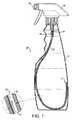
図1は、本発明における流体ディスペンサー10の一例を示す。流体ディスペンサー10は、従来のトリガースプレー式のディスペンサーヘッド12に嵌合された中空のプラスチックボトル11を有する。流体ディスペンサー10は、一定の長さの中空のメンブレンから形成されたディップチューブ13を含み、この中空のメンブレンは、トリガースプレーヘッド12の流体ポート15に連結されてトリガースプレーヘッド12の出口16と連通可能な開口端14と、ボトル11の本体内の閉端17とを有する。 FIG. 1 shows an example of a fluid dispenser 10 according to the present invention. The fluid dispenser 10 has a hollow plastic bottle 11 fitted to a conventional trigger spray dispenser head 12. The fluid dispenser 10 includes a
トリガースプレー12が手動で駆動されると、ディップチューブ13の壁18に沿って圧力差が生じ、ディップチューブの面の全部分と接触しているボトル内の全液体がディップチューブ13の壁18を透過して、内部ボア19沿いに出口16へ向かう。この流体ディスペンサーは、このようにして実質的にどの向きでも作動することができ、ボトルの内容物全体を実質的に放出することができるという効果を奏する。 When the trigger spray 12 is driven manually, a pressure difference is created along the wall 18 of the
製造業者に対して、従来のコンテナで見られるコンテナの寿命が尽きたときに製品がコンテナ内に残ってしまうことの埋め合わせのためにコンテナ内により多くの製品および推進剤を導入するよう法律で課している国においては、内容物全体を実質的に放出することができるようになることで利点が生じるであろう。例えば、330mlの量の製品が入っていると記載されているコンテナは実際には350mlを含みうるので、従来のディップチューブでは通常20ml程度がコンテナ内に残ることとなる。 The law requires manufacturers to introduce more products and propellants into the container to make up for the product remaining in the container when the lifetime of the container found in conventional containers is exhausted. In those countries, it would be advantageous to be able to release the entire contents substantially. For example, a container that is described as containing 330 ml of product can actually contain 350 ml, so a conventional dip tube will usually leave about 20 ml in the container.
本発明によるディップチューブ13としての利用に適した中空の繊維メンブレンは市場で入手可能であり、Norit(www.norit.com)のX−flow(登録商標))などを利用することができる。 A hollow fiber membrane suitable for use as the
好適なディップチューブの細孔径は、0.01ミクロンから250ミクロンの範囲である。ディップチューブの正確な細孔径、壁厚、長さ、形状および構成、内部ボア、色、および透明度は、放出対象の流体、および/または、利用される推進剤、放出された後の流体の性質(つまり、泡の堅さ、生成される霧の細かさ、噴霧化される度合い、製品への推進剤の混合、コンテナ本体の性質(例えばサイズ、形状、および色))に従って選択することができる。 Suitable dip tube pore sizes range from 0.01 microns to 250 microns. The exact pore size, wall thickness, length, shape and configuration of the dip tube, the internal bore, color, and transparency are the properties of the fluid to be released and / or the propellant utilized, the fluid after being released (Ie, the firmness of the foam, the fineness of the mist produced, the degree of atomization, the mixing of the propellant into the product, the nature of the container body (eg size, shape and color)) .
ディップチューブの外径は、ディスペンサーヘッドの流体ポートおよびその他の接続部の内径および外径に従って選択されてよい。 The outer diameter of the dip tube may be selected according to the inner and outer diameters of the fluid port and other connections of the dispenser head.
ディップチューブを形成する際に利用される中空の繊維メンブレンは、一端を熱封止/溶接、圧着、接着、化学的封止、および超音波または高周波溶接により閉じることができる。 The hollow fiber membrane utilized in forming the dip tube can be closed at one end by heat sealing / welding, crimping, bonding, chemical sealing, and ultrasonic or high frequency welding.
ディップチューブの中空の繊維メンブレンは、ポリテトラフルオロエチレン、ポリアミド、ポリイミド、ポリスルフォン、ポリエーテルスルフォン、ポリフッ化ビニリデン、ポリプロピレン、ポリ窒化ビニル、ポリビニルピロリドン、ポリカーボネート、ポリアクリロニトリル、セルロース、酢酸セルロース、およびその混合物、混成物、および共重合体からなる群から選択された材料を含むと好適である。 The hollow fiber membrane of the dip tube is made of polytetrafluoroethylene, polyamide, polyimide, polysulfone, polyethersulfone, polyvinylidene fluoride, polypropylene, polyvinyl nitride, polyvinylpyrrolidone, polycarbonate, polyacrylonitrile, cellulose, cellulose acetate, and its It is preferred to include a material selected from the group consisting of mixtures, hybrids, and copolymers.
ディップチューブの中空繊維メンブレンの好適な材料は、ポリスルフォン、ポリエーテルスルフォン、ポリフッ化ビニリデン、ポリビニルピロリデン、ポリアクリロニトリル、セルロース、酢酸セルロース、およびその混合物、混成物、および共重合体からなる群から選択される。 Suitable materials for the hollow fiber membrane of the dip tube are from the group consisting of polysulfone, polyethersulfone, polyvinylidene fluoride, polyvinylpyrrolidene, polyacrylonitrile, cellulose, cellulose acetate, and mixtures, hybrids, and copolymers thereof. Selected.
特に好適な中空の繊維メンブレン材料は、ポリエーテルスルフォンおよびポリビニルピロリドンの混成物からなる。ポリエーテルスルフォン(PES)およびポリビニルピロリドン(PVP)の混成物は、酸化剤に対する耐性が高く(塩素に対して>250,000ppm時間の耐性を有し、過マンガンおよびオゾンにも耐性を有する)、幅広いpH範囲に耐えることができ、親水性が高い。 A particularly suitable hollow fiber membrane material consists of a mixture of polyethersulfone and polyvinylpyrrolidone. A mixture of polyethersulfone (PES) and polyvinylpyrrolidone (PVP) is highly resistant to oxidants (> 250,000 ppm hour resistant to chlorine and resistant to permanganese and ozone), It can withstand a wide pH range and has high hydrophilicity.
ディップチューブは好適には、少なくとも500Paの最小作動圧力差で作動する。高圧システムでは、作動圧力差が1000kPaになる場合もある。 The dip tube preferably operates with a minimum operating pressure differential of at least 500 Pa. In a high pressure system, the operating pressure difference may be 1000 kPa.
図2は、本発明による流体ディスペンサー20の別の例を示す。本例では、コンテナは、従来のエアロゾルプッシュボタンスプレーヘッド22を有する従来のエアロゾルスプレーキャニスター21であるが、エアロゾルディスペンサーヘッドの流体ポート24に連結されて出口25と連通可能な開口端と、スプレーキャニスターの本体内の閉端とを有し、中空の繊維メンブレンから形成されるディップチューブ23を有する。 FIG. 2 shows another example of a
スプレーキャニスター21は、自己加圧式であり、放出する流体に加えて適切な推進剤を含む。推進剤は、圧力差を生じ、プッシュボタンが手動で駆動されると、ディップチューブ23の面の全部分と接触しているボトル内の全液体がディップチューブの壁を透過して、内部ボア沿いに出口25へ向かう。このスプレーキャニスターは、実質的にどの向きでも作動することができ、キャニスターの内容物全体を実質的に放出することができるという効果を奏する。利用する推進剤が液化ガスである場合には、推進剤は液体の状態で放出される。 The
図3は、本発明の流体ディスペンサー30のまた別の例を示す。本例では、コンテナ31は、従来のプッシュボタンアトマイザーヘッド32を有する従来の香水ボトルであるが、アトマイザーヘッドの流体ポート34に連結されて出口35と連通可能な開口端と、ボトルの本体内の閉端とを有し、中空の繊維メンブレンから形成されるディップチューブ33を有する。 FIG. 3 shows yet another example of a fluid dispenser 30 of the present invention. In this example, the
プッシュボタンが手動で駆動されると、ディップチューブ33の壁に沿って圧力差が生じる。ディップチューブ33の面の全部分と接触しているボトル31内の全液体がディップチューブ33の壁を透過して、内部ボア沿いに出口35へ向かう。この香水ボトルは、実質的にどの向きでも作動することができ、ボトルの内容物全体を実質的に放出することができるという効果を奏する。 When the push button is driven manually, a pressure difference is produced along the wall of the
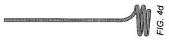
図1から図3の例に示すディップチューブは、各コンテナの対向する双側壁および基部に接触して、なるべくコンテナ内の液体が、コンテナの向きに関らずディップチューブに実質的に常に接触するよう配置されている。しかしながら他の構成もまた可能である。コンテナ内のディップチューブの構成もまた、コンテナの形状および放出対象の内容物に応じて選択可能である。図4A、図4B、図4C、図4D、図4Eは、利用可能であることが予想される様々なディップチューブの構成の数例を示している。 The dip tube shown in the example of FIGS. 1 to 3 is in contact with the opposite side walls and the base of each container, so that the liquid in the container is in contact with the dip tube substantially always regardless of the orientation of the container. It is arranged as follows. However, other configurations are also possible. The configuration of the dip tube in the container can also be selected depending on the shape of the container and the contents to be discharged. 4A, 4B, 4C, 4D, and 4E show several examples of various dip tube configurations that are expected to be available.
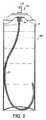
図5Aおよび図5Bは、本発明における流体ディスペンサー50のさらなる例を示す。コンテナ51の側壁は、折り畳み式で折り畳まれている。図5Aは流体ディスペンサーが直立しているときの構成を示し、図5Bは、流体ディスペンサーが折り畳まれているときの構成を示す。折り畳み式の設計は、コンテナが通常、ある国あるいは場所で製造され、配送された後で内容物を充填されることが多いことから、コンテナの格納および発送時の体積を減少させる目的に特に好適である。 5A and 5B show a further example of a
この例のコンテナ51は、従来のプッシュボタンスプレーヘッド52を有するが、中空の繊維メンブレンから形成された折り畳み式の螺旋形状のディップチューブ53を有する。中空の繊維メンブレンからなるディップチューブ53は、出口55と連通可能なようにエアロゾルディスペンサーヘッドの流体ポート54に連結された開口端56と、コンテナ51の本体内の閉端57とを有する。本例では、ディップチューブ53の閉端57は、コンテナ51の床部に取り付けられて、コンテナの側壁が伸ばされる際にコイル状態から伸ばされる。 The
コンテナおよびディップチューブは、コンテナの形状および側壁の形成に利用される材料に応じて、折り畳まれた際の体積を最小化させることのできる他の折り畳み可能な構成とすることもできる。 The container and dip tube may be other foldable configurations that can minimize the volume when folded, depending on the shape of the container and the material utilized to form the sidewalls.
本発明の流体ディスペンサーは、多くの異なる流体(ジェルおよび泡を含む)を放出する用途に幅広く利用可能である。 The fluid dispenser of the present invention is widely available for applications that release many different fluids (including gels and foams).
流体ディスペンサーの幅広い用途としては、台所用製品、香水、デオドラント製品、および制汗剤、スプレー式塗料、整髪製品、液体/泡状/ジェル状製品、および殺虫剤が挙げられる。もちろん他にも数多くある。 A wide range of uses for fluid dispensers include kitchen products, perfumes, deodorant products, and antiperspirants, spray paints, hair styling products, liquid / foam / gel products, and insecticides. Of course there are many others.
当技術分野で知られている通常のディスペンサーヘッドは、トリガースプレー、アトマイザー、エアロゾルスプレー、香水スプレー、ローションポンプ、泡ポンプ、吸入器、およびマイクロスクリューポンプを含む。これらのうち任意のものが上述した中空の繊維メンブレンからなるディップチューブとともに利用されることで、本発明の効果を奏することが可能である。ディスペンサーヘッドは、流体をスプレー、ストリーム、泡、細かい霧、またはジェル形状で放出することができる。 Conventional dispenser heads known in the art include trigger sprays, atomizers, aerosol sprays, perfume sprays, lotion pumps, foam pumps, inhalers, and micro screw pumps. By using any of these together with the dip tube made of the hollow fiber membrane described above, the effects of the present invention can be achieved. The dispenser head can release fluid in the form of a spray, stream, foam, fine mist, or gel.
適切なコンテナには、プラスチック、ガラス、金属、セラミックス、紙、または合成物からなるものが含まれる。好適な実施形態の一部におけるコンテナには、可撓性の壁が設けられており、従って手で握った際に、流体を中空のメンブレンからなるディップチューブの壁を強制的に透過させて、対応するディスペンサーヘッドの出口へと流すのに足る圧力差が生じさせることができるようなものもある。 Suitable containers include those made of plastic, glass, metal, ceramics, paper, or composite. The container in some of the preferred embodiments is provided with a flexible wall so that when gripped by hand, the fluid is forced through the wall of the dip tube consisting of a hollow membrane, Some are capable of producing a pressure differential sufficient to flow to the outlet of the corresponding dispenser head.
上述した例においては、1つのディップチューブのみが提供されていたが、好適な実施形態の一部では、2以上の数のディップチューブを提供してもよい。これらディップチューブは、同じ材料特性および性能を有するものであってよい。またこれらディップチューブは、細孔のサイズ、壁厚、剛性、形状、材料、結合位置および長さ等を異ならせることにより、それぞれ異なる性能を有するよう製造することもできる。 In the example described above, only one dip tube was provided, but in some preferred embodiments, more than two dip tubes may be provided. These dip tubes may have the same material properties and performance. These dip tubes can also be manufactured to have different performances by varying the size, wall thickness, rigidity, shape, material, bonding position, length, etc. of the pores.
ディップチューブは、ディスペンサーヘッドに直接結合させることも(例示してきたように)、あるいは、別のチューブ(another length of tubing)を介することでディスペンサーヘッドに間接的に連結することもできる。 The dip tube can be coupled directly to the dispenser head (as illustrated) or indirectly connected to the dispenser head via another length of tubing.
Claims (14)
Translated fromJapanese液体用のコンテナと、
前記コンテナに嵌合され、流体出口を有するディスペンサーヘッドと、
一定の長さの中空のメンブレンから形成されたディップチューブと
を備え、
前記中空のメンブレンは、前記流体出口と連通するよう前記ディスペンサーヘッドと連結された開口端と、前記コンテナ内の閉端とを有し、
前記中空のメンブレンは、液体を気体よりも優先して通過させ、前記ディスペンサーヘッドが駆動されたときに、前記メンブレンの壁に沿って生じる圧力差のもとで、液体が前記液体コンテナから前記ディップチューブの壁を透過して前記流体出口へと向かう
流体ディスペンサー。A fluid dispenser,
A container for liquid,
A dispenser head fitted into the container and having a fluid outlet;
A dip tube formed from a hollow membrane of a certain length, and
The hollow membrane has an open end connected to the dispenser head to communicate with the fluid outlet, and a closed end in the container;
The hollow membrane allows liquid to pass preferentially over gas and causes liquid to dip from the liquid container under pressure differences that occur along the membrane wall when the dispenser head is driven. A fluid dispenser that passes through the wall of the tube and travels toward the fluid outlet.
Applications Claiming Priority (3)
| Application Number | Priority Date | Filing Date | Title |
|---|---|---|---|
| US12/240,664US8091741B2 (en) | 2006-09-25 | 2008-09-29 | Fluid dispenser |
| US12/240,664 | 2008-09-29 | ||
| PCT/GB2009/002261WO2010034983A1 (en) | 2008-09-29 | 2009-09-22 | A fluid dispenser |
Publications (2)
| Publication Number | Publication Date |
|---|---|
| JP2012504079A JP2012504079A (en) | 2012-02-16 |
| JP5532266B2true JP5532266B2 (en) | 2014-06-25 |
Family
ID=41482453
Family Applications (1)
| Application Number | Title | Priority Date | Filing Date |
|---|---|---|---|
| JP2011528413AExpired - Fee RelatedJP5532266B2 (en) | 2008-09-29 | 2009-09-22 | Fluid dispenser |
Country Status (6)
| Country | Link |
|---|---|
| US (1) | US8091741B2 (en) |
| EP (1) | EP2342146B1 (en) |
| JP (1) | JP5532266B2 (en) |
| CN (1) | CN102164831B (en) |
| AU (1) | AU2009295702B2 (en) |
| WO (1) | WO2010034983A1 (en) |
Families Citing this family (30)
| Publication number | Priority date | Publication date | Assignee | Title |
|---|---|---|---|---|
| US20090008414A1 (en)* | 2005-02-18 | 2009-01-08 | Michael Tinsley | Sure Shot |
| GB2443608B (en)* | 2006-09-25 | 2008-11-12 | Michael Pritchard | A water purifying device |
| CN101885923B (en)* | 2009-05-13 | 2014-04-23 | 鸿富锦精密工业(深圳)有限公司 | Conductive foam and method of use thereof |
| EP2455126B2 (en) | 2010-11-15 | 2023-06-14 | F. Hoffmann-La Roche AG | Container for storing medical or pharmaceutical liquids |
| US9701430B2 (en) | 2011-05-16 | 2017-07-11 | The Procter & Gamble Company | Components for aerosol dispenser |
| JP5793371B2 (en)* | 2011-08-23 | 2015-10-14 | 株式会社初田製作所 | Fire extinguisher storage container and fire extinguisher equipped with the same |
| US9498554B2 (en) | 2012-07-24 | 2016-11-22 | S.C. Johnson & Son, Inc. | Dispensing device |
| AR091887A1 (en) | 2012-07-24 | 2015-03-11 | Johnson & Son Inc S C | VOLATILE MATERIAL DISPENSING SYSTEM |
| USD730505S1 (en) | 2012-07-24 | 2015-05-26 | S.C. Johnson & Son, Inc. | Dispensing device |
| US10694747B2 (en) | 2012-11-21 | 2020-06-30 | S. C. Johnson & Son, Inc. | Dispenser comprising only one single hinge |
| US9227211B2 (en)* | 2013-02-06 | 2016-01-05 | Elizabeth M Sammons | Spray dispenser and method for using |
| HUE027578T2 (en)* | 2013-06-03 | 2016-10-28 | Dentsply Ih Ab | Cylindrical collapsible container |
| JP2015002921A (en)* | 2013-06-21 | 2015-01-08 | パナソニックIpマネジメント株式会社 | Oral cleaning device |
| JP5850207B2 (en)* | 2013-12-20 | 2016-02-03 | 大日本印刷株式会社 | Chemical container, chemical nozzle, liquid filling method, and liquid discharging method |
| US9527095B2 (en)* | 2014-06-03 | 2016-12-27 | Solomon L. Kim | Pumping nozzle including suction tube having multiple openings, and pump type container using the same |
| US9604238B2 (en)* | 2014-07-03 | 2017-03-28 | Stephen F. C. Geldard | Multiple input dip tube |
| USD782606S1 (en) | 2015-07-02 | 2017-03-28 | Flambeau, Inc. | Bait container |
| WO2017064621A1 (en)* | 2015-10-13 | 2017-04-20 | Airopack Technology Group Ag | Fluid dispenser |
| US10144021B2 (en) | 2015-12-11 | 2018-12-04 | Michael Tinsley | Container with improved liquid dispensing ability |
| WO2017156438A1 (en)* | 2016-03-10 | 2017-09-14 | Ecolab Usa Inc. | Measured dosing and spray bottle for multi-use applications and associated method of using |
| JP2017210251A (en)* | 2016-05-24 | 2017-11-30 | 株式会社三谷バルブ | Metering valve device and aerosol sprayer container using the same |
| US10207061B2 (en)* | 2016-08-25 | 2019-02-19 | Michelle Vidal | Multi-chambered dispenser for the topical application of infused fluid |
| US11161661B2 (en) | 2017-09-13 | 2021-11-02 | The Procter & Gamble Company | Aerosol dispenser with valve anti-removal feature |
| WO2019084054A1 (en)* | 2017-10-27 | 2019-05-02 | Ozone Clean Technologies, Inc. | Portable water treatment system using ozone |
| WO2019094980A1 (en)* | 2017-11-13 | 2019-05-16 | Ozone Clean Technologies, Inc. | Water treatment system using ozone |
| GB202005499D0 (en)* | 2020-04-15 | 2020-05-27 | Pritchard Spray Ip Ltd | An aerosol dispenser |
| FR3113909B1 (en)* | 2020-09-10 | 2022-08-26 | Commissariat Energie Atomique | KIT FOR ANALYSIS AND MONITORING OF A PARAMETER, BY MEANS OF A MOBILE SENSOR, OF A CHEMICAL OR BIOCHEMICAL OR BIOLOGICAL REACTION IN A REACTION CHAMBER |
| US11535415B2 (en) | 2021-03-16 | 2022-12-27 | Berlin Packaging, Llc | Compressible and expandable bottle |
| USD998472S1 (en) | 2021-03-17 | 2023-09-12 | Berlin Packaging, Llc | Expandable bottle |
| GB2631709A (en) | 2023-07-10 | 2025-01-15 | Athos Medical Tech Ltd | Liquid metering dispensing apparatus and method of metering thereof |
Family Cites Families (26)
| Publication number | Priority date | Publication date | Assignee | Title |
|---|---|---|---|---|
| US2681252A (en)* | 1951-01-17 | 1954-06-15 | Bridgeport Brass Co | Spray device |
| BE623486A (en)* | 1961-10-18 | |||
| US3184118A (en)* | 1963-06-14 | 1965-05-18 | Bernz O Matic Corp | Aerosol spray container |
| US3209954A (en)* | 1963-11-07 | 1965-10-05 | Bernz O Matic Corp | Aerosol spray container and filter |
| US3785537A (en)* | 1970-12-03 | 1974-01-15 | V Appleby | Dispenser for immiscible liquids |
| US3788521A (en)* | 1972-07-10 | 1974-01-29 | Laauwe Robert H | Aerosol package |
| US4142652A (en)* | 1977-09-02 | 1979-03-06 | Warner-Lambert Company | Aerosol metering |
| US4398654A (en)* | 1978-12-26 | 1983-08-16 | American Cyanamid Company | Aerosol dispensing system |
| US4418846A (en)* | 1980-01-04 | 1983-12-06 | American Cyanamid Company | Aerosol dispensing system |
| US4530450A (en)* | 1983-02-07 | 1985-07-23 | American Cyanamid Co. | Aerosol dispensing system |
| JPH0755286B2 (en)* | 1988-04-21 | 1995-06-14 | トーメー産業株式会社 | Simple liquid purification device |
| JP2781432B2 (en)* | 1989-12-01 | 1998-07-30 | 日本ミリポア株式会社 | Filter structure for liquid container with pump |
| JP2888902B2 (en) | 1990-03-03 | 1999-05-10 | トーメー産業株式会社 | Attachment for simple liquid purification |
| FR2687643B1 (en)* | 1992-02-24 | 1995-04-28 | Oreal | FLUID DISPENSER CONTAINER. |
| DE4231826A1 (en)* | 1992-09-23 | 1994-03-24 | Wunsch Eckart | Device for atomizing liquids |
| JPH08133358A (en)* | 1994-11-04 | 1996-05-28 | Masayuki Hayashi | Variable capacity spray container |
| US5552046A (en) | 1995-01-23 | 1996-09-03 | Johnston; Arthur W. | Multi-stage microbiological water filter |
| CN1122540C (en)* | 1995-06-07 | 2003-10-01 | 亚历山大·乔治·布赖恩·奥尼尔 | Patient controlled drug delivery device |
| US5875933A (en)* | 1996-03-18 | 1999-03-02 | Ellion; M. Edmund | Invertible spray dispensing container |
| US5897032A (en)* | 1996-03-18 | 1999-04-27 | Ellion; M. Edmund | Invertible spray dispensing container |
| US5934519A (en)* | 1997-11-17 | 1999-08-10 | Kim; Hee Soo | Weighted dip tube |
| US6379544B1 (en) | 2000-12-19 | 2002-04-30 | Han-Ming Chen | Portable device for supplying filtered water |
| US6820769B2 (en)* | 2003-03-12 | 2004-11-23 | Continental Afa Dispensing Company | Child proof connection for remote trigger sprayer and bottle container |
| JP2006027650A (en)* | 2004-07-15 | 2006-02-02 | Yukihiro Hirose | Bag |
| WO2006021966A1 (en) | 2004-08-24 | 2006-03-02 | Mon Chatrath | Improvement in or relating to personal filter bottle |
| GB2443608B (en)* | 2006-09-25 | 2008-11-12 | Michael Pritchard | A water purifying device |
- 2008
- 2008-09-29USUS12/240,664patent/US8091741B2/ennot_activeExpired - Fee Related
- 2009
- 2009-09-22EPEP09740915.5Apatent/EP2342146B1/ennot_activeNot-in-force
- 2009-09-22CNCN200980138257.0Apatent/CN102164831B/ennot_activeExpired - Fee Related
- 2009-09-22WOPCT/GB2009/002261patent/WO2010034983A1/enactiveApplication Filing
- 2009-09-22JPJP2011528413Apatent/JP5532266B2/ennot_activeExpired - Fee Related
- 2009-09-22AUAU2009295702Apatent/AU2009295702B2/ennot_activeCeased
Also Published As
| Publication number | Publication date |
|---|---|
| CN102164831A (en) | 2011-08-24 |
| AU2009295702A1 (en) | 2010-04-01 |
| AU2009295702B2 (en) | 2014-06-12 |
| US8091741B2 (en) | 2012-01-10 |
| JP2012504079A (en) | 2012-02-16 |
| CN102164831B (en) | 2014-05-07 |
| HK1159580A1 (en) | 2012-08-03 |
| EP2342146B1 (en) | 2014-05-21 |
| WO2010034983A1 (en) | 2010-04-01 |
| EP2342146A1 (en) | 2011-07-13 |
| US20090071983A1 (en) | 2009-03-19 |
Similar Documents
| Publication | Publication Date | Title |
|---|---|---|
| JP5532266B2 (en) | Fluid dispenser | |
| EP2855029B1 (en) | A foam dispenser | |
| US6056213A (en) | Modular system for atomizing a liquid | |
| US20150166252A1 (en) | Compressed Gas Dispensers | |
| US20130068797A1 (en) | Manual pump type fluid dispenser | |
| TW201020030A (en) | Handheld dispensers for personal use | |
| US20160263602A1 (en) | Pressure multiplying aerosol pump | |
| JP2009545433A (en) | Nozzle and dispenser including nozzle | |
| US7735754B2 (en) | Flat atomizer pump | |
| US20240091800A1 (en) | Spray dispenser | |
| HK1159580B (en) | A fluid dispenser | |
| US20150166251A1 (en) | Compressed Gas Dispensers | |
| US20240001382A1 (en) | Spray dispenser | |
| HK1220662B (en) | A foam dispenser | |
| EP1917106A1 (en) | A nozzle and a dispenser having such a nozzle | |
| HK1202483B (en) | A foam dispenser |
Legal Events
| Date | Code | Title | Description |
|---|---|---|---|
| A621 | Written request for application examination | Free format text:JAPANESE INTERMEDIATE CODE: A621 Effective date:20120319 | |
| A521 | Request for written amendment filed | Free format text:JAPANESE INTERMEDIATE CODE: A523 Effective date:20130430 | |
| A977 | Report on retrieval | Free format text:JAPANESE INTERMEDIATE CODE: A971007 Effective date:20130822 | |
| A131 | Notification of reasons for refusal | Free format text:JAPANESE INTERMEDIATE CODE: A131 Effective date:20130903 | |
| TRDD | Decision of grant or rejection written | ||
| A01 | Written decision to grant a patent or to grant a registration (utility model) | Free format text:JAPANESE INTERMEDIATE CODE: A01 Effective date:20140401 | |
| A61 | First payment of annual fees (during grant procedure) | Free format text:JAPANESE INTERMEDIATE CODE: A61 Effective date:20140408 | |
| R150 | Certificate of patent or registration of utility model | Ref document number:5532266 Country of ref document:JP Free format text:JAPANESE INTERMEDIATE CODE: R150 | |
| S111 | Request for change of ownership or part of ownership | Free format text:JAPANESE INTERMEDIATE CODE: R313113 | |
| S531 | Written request for registration of change of domicile | Free format text:JAPANESE INTERMEDIATE CODE: R313531 | |
| R350 | Written notification of registration of transfer | Free format text:JAPANESE INTERMEDIATE CODE: R350 | |
| R250 | Receipt of annual fees | Free format text:JAPANESE INTERMEDIATE CODE: R250 | |
| R250 | Receipt of annual fees | Free format text:JAPANESE INTERMEDIATE CODE: R250 | |
| R250 | Receipt of annual fees | Free format text:JAPANESE INTERMEDIATE CODE: R250 | |
| R250 | Receipt of annual fees | Free format text:JAPANESE INTERMEDIATE CODE: R250 | |
| R250 | Receipt of annual fees | Free format text:JAPANESE INTERMEDIATE CODE: R250 | |
| R250 | Receipt of annual fees | Free format text:JAPANESE INTERMEDIATE CODE: R250 | |
| LAPS | Cancellation because of no payment of annual fees |