JP5529174B2 - Water server - Google Patents
Water serverDownload PDFInfo
- Publication number
- JP5529174B2 JP5529174B2JP2012001291AJP2012001291AJP5529174B2JP 5529174 B2JP5529174 B2JP 5529174B2JP 2012001291 AJP2012001291 AJP 2012001291AJP 2012001291 AJP2012001291 AJP 2012001291AJP 5529174 B2JP5529174 B2JP 5529174B2
- Authority
- JP
- Japan
- Prior art keywords
- water
- cold water
- water tank
- baffle
- transfer
- Prior art date
- Legal status (The legal status is an assumption and is not a legal conclusion. Google has not performed a legal analysis and makes no representation as to the accuracy of the status listed.)
- Active
Links
Images


Classifications
- B—PERFORMING OPERATIONS; TRANSPORTING
- B67—OPENING, CLOSING OR CLEANING BOTTLES, JARS OR SIMILAR CONTAINERS; LIQUID HANDLING
- B67D—DISPENSING, DELIVERING OR TRANSFERRING LIQUIDS, NOT OTHERWISE PROVIDED FOR
- B67D3/00—Apparatus or devices for controlling flow of liquids under gravity from storage containers for dispensing purposes
- B67D3/0009—Apparatus or devices for controlling flow of liquids under gravity from storage containers for dispensing purposes provided with cooling arrangements
- B—PERFORMING OPERATIONS; TRANSPORTING
- B67—OPENING, CLOSING OR CLEANING BOTTLES, JARS OR SIMILAR CONTAINERS; LIQUID HANDLING
- B67D—DISPENSING, DELIVERING OR TRANSFERRING LIQUIDS, NOT OTHERWISE PROVIDED FOR
- B67D3/00—Apparatus or devices for controlling flow of liquids under gravity from storage containers for dispensing purposes
- B67D3/0022—Apparatus or devices for controlling flow of liquids under gravity from storage containers for dispensing purposes provided with heating arrangements
- B—PERFORMING OPERATIONS; TRANSPORTING
- B67—OPENING, CLOSING OR CLEANING BOTTLES, JARS OR SIMILAR CONTAINERS; LIQUID HANDLING
- B67D—DISPENSING, DELIVERING OR TRANSFERRING LIQUIDS, NOT OTHERWISE PROVIDED FOR
- B67D3/00—Apparatus or devices for controlling flow of liquids under gravity from storage containers for dispensing purposes
- B67D3/0025—Apparatus or devices for controlling flow of liquids under gravity from storage containers for dispensing purposes provided with dispensing valves actuated by the receptacle to be filled
- B—PERFORMING OPERATIONS; TRANSPORTING
- B67—OPENING, CLOSING OR CLEANING BOTTLES, JARS OR SIMILAR CONTAINERS; LIQUID HANDLING
- B67D—DISPENSING, DELIVERING OR TRANSFERRING LIQUIDS, NOT OTHERWISE PROVIDED FOR
- B67D3/00—Apparatus or devices for controlling flow of liquids under gravity from storage containers for dispensing purposes
- B67D3/0038—Apparatus or devices for controlling flow of liquids under gravity from storage containers for dispensing purposes the liquid being stored in an intermediate container prior to dispensing
- B—PERFORMING OPERATIONS; TRANSPORTING
- B67—OPENING, CLOSING OR CLEANING BOTTLES, JARS OR SIMILAR CONTAINERS; LIQUID HANDLING
- B67D—DISPENSING, DELIVERING OR TRANSFERRING LIQUIDS, NOT OTHERWISE PROVIDED FOR
- B67D3/00—Apparatus or devices for controlling flow of liquids under gravity from storage containers for dispensing purposes
- B67D3/0058—Details
- B67D3/0061—Details of liquid containers, e.g. filling, emptying, closing or opening means
Landscapes
- Engineering & Computer Science (AREA)
- Mechanical Engineering (AREA)
- Devices For Dispensing Beverages (AREA)
Description
Translated fromJapaneseこの発明は、タンク内の貯留水を冷やして飲料用に供給し得るウォーターサーバーに関する。 The present invention relates to a water server capable of cooling stored water in a tank and supplying it for drinks.
この種のウォーターサーバーは、貯留水を冷却する冷水タンク内の水量が減ると、自動的に水導入路からタンク内に水が送られ、冷水タンクに付設の熱交換器でタンク内の貯留水を冷却し、ユーザのレバー操作やコック操作によって弁が開き、冷水タンクで冷やされた水が冷水注出路を経て大気に注出されるようになっている。冷水タンク内の貯留水は、タンク底部に近い程、冷たくなる。水導入路から冷水タンクに流入した水がタンク底部までそのまま下降することを許すと、よく冷えたタンク底部近傍の水と早々に混ざり、好ましくない。これを防ぐため、冷水タンク内には、流入した水の下降を邪魔するバッフルが設けられている(例えば、特許文献1〜3)。 In this type of water server, when the amount of water in the cold water tank that cools the stored water decreases, the water is automatically sent from the water introduction path into the tank, and the water stored in the tank is stored in the heat exchanger attached to the cold water tank. Then, the valve is opened by the user's lever operation or cock operation, and the water cooled in the cold water tank is poured out into the atmosphere through the cold water pouring channel. The stored water in the cold water tank gets colder as it gets closer to the bottom of the tank. If the water flowing into the cold water tank from the water introduction path is allowed to descend to the bottom of the tank as it is, it will be mixed with the water in the vicinity of the well-cooled tank quickly, which is not preferable. In order to prevent this, a baffle is provided in the cold water tank to obstruct the descent of the inflowing water (for example,
冷水タンクの底部からバッフルの最大外周部までの高さになる冷水タンク下部内には、バッフル上の水温より低い低水温層が底部側から生じる。冷水注出路は、低水温層の水を注出するように設けられている。バッフルの最大外周部と冷水タンクの内周とを嵌合、又はこれらの間の隙間を水平方向に狭くする程、冷水タンク内を上下に隔てるバッフル面積を増やし、前記の邪魔性能を高めることは可能だが、バッフル上から冷水タンク下部への通水性が不足し易くなる。このような場合、バッフルのうち、最大外周部より内側に、水導入路から流入した水をバッフル上から冷水タンク下部へ通す移流路が設けられている。 A low water temperature layer lower than the water temperature on the baffle is generated from the bottom side in the lower part of the cold water tank, which has a height from the bottom of the cold water tank to the maximum outer periphery of the baffle. The cold water pouring channel is provided so as to pour out water of a low water temperature layer. The larger the baffle area that vertically separates the inside of the cold water tank, the higher the baffle performance, as the maximum outer peripheral part of the baffle and the inner circumference of the cold water tank are fitted or the gap between them is reduced in the horizontal direction. Although possible, water permeability from the top of the baffle to the bottom of the cold water tank tends to be insufficient. In such a case, a transfer passage is provided inside the baffle, inside the maximum outer peripheral portion, for passing water flowing in from the water introduction path from above the baffle to the lower part of the cold water tank.
移流路の終端口は、冷水タンクの内周とバッフルの最大外周部間の隙間同様、上下方向に真直ぐ向いており、その終端口から冷水タンク下部へ放つ水の流線方向は、実質的に下向きになっている。バッフル上面に露出する移流路の始端口の流路断面積を小さくすれば、移流路を通過する水の勢いを弱めることが可能なため、移流路の終端口から水を下向きへ放つことは、特に問題視されていない。 The end of the transfer channel is straight in the vertical direction, as is the gap between the inner periphery of the cold water tank and the maximum outer periphery of the baffle, and the streamline direction of the water discharged from the end port to the lower part of the cold water tank is substantially It is facing down. If the flow cross-sectional area of the start end of the transfer channel exposed on the baffle upper surface is reduced, the momentum of the water passing through the transfer channel can be reduced, so releasing water downward from the end of the transfer channel is There is no particular problem.
しかしながら、バッフルの取り付け、形状単純化等のため、冷水タンクの内周とバッフルの最大外周部間の隙間を無くし、又は狭くし、少ない数の移流路で通水性を確保しようとする程、移流路の流路断面積を全長において大きくしなければならず、移流路の終端口から冷水タンク下部へ下向きに放つ水の勢いが増し、低水温層に早く混ざり易くなる、という懸念が生じる。 However, for the purpose of mounting the baffle, simplifying the shape, etc., the gap between the inner circumference of the cold water tank and the maximum outer circumference of the baffle is eliminated or narrowed, and the advection is made so as to ensure water permeability with a small number of transfer channels. There is a concern that the cross-sectional area of the channel must be increased over the entire length, and the momentum of the water released downward from the end of the transfer channel to the lower part of the cold water tank increases, and it becomes easy to mix with the low water temperature layer quickly.
そこで、この発明が解決しようとする課題は、バッフルの移流路から冷水タンク下部へ放つ水が低水温層に混ざり難くすることにある。 Therefore, the problem to be solved by the present invention is to make it difficult for water released from the transfer passage of the baffle to the lower part of the cold water tank to be mixed into the low water temperature layer.
上記の課題を達成するため、この発明は、要するに、移流路を、上下方向に非貫通であって、水平方向に近い向きで冷水タンク下部に水を放つ流路から構成した。上下方向に非貫通の移流路なので、水導入路から流入した水が下降しても、上下方向に真直ぐにバッフルを通過することはできず、移流路の始端口の流路断面積を大きくしても、バッフルが冷水タンク内を上下方向に隔てる面積は減少しない。また、上下方向に非貫通の移流路を採用すれば、下降する水の流線を水平方向に近い向きに曲げてから、移流路の終端口まで導くことができ、その終端口も、バッフルの側面に開放させることができる。したがって、移流路の終端口からは、水平方向に近い向きで冷水タンク下部へ水を放つことが可能である。ここで、「水平方向に近い向き」とは、水平方向、及び水平方向に対して上方又は下方に45°未満の方向の双方を含む意味である。移流路から水平方向に近い向きの流線で放たれた水は、冷水タンク下部を真直ぐ下降せず、水平方向にも流れるので、冷水タンク下部の底部側から生じる低水温層と混ざるまでの移流距離が延び、したがって、低水温層に混ざり難くなる。 In order to achieve the above object, in short, the present invention is configured such that the transfer flow path is a non-penetration in the vertical direction and discharges water to the lower part of the cold water tank in a direction close to the horizontal direction. Since the transfer channel is non-penetrating in the vertical direction, even if the water flowing in from the water introduction channel drops, it cannot pass through the baffle straight in the vertical direction, and the channel cross-sectional area at the start end of the transfer channel is increased. However, the area where the baffle separates the inside of the cold water tank in the vertical direction does not decrease. In addition, by adopting a non-penetrating transfer channel in the vertical direction, the descending flow line of water can be bent to a direction close to the horizontal direction and then guided to the terminal end of the transfer channel. It can be opened to the side. Therefore, it is possible to discharge water from the terminal end of the transfer channel to the lower part of the cold water tank in a direction close to the horizontal direction. Here, the “direction close to the horizontal direction” means to include both the horizontal direction and a direction less than 45 ° above or below the horizontal direction. The water released from the transfer channel in the direction of the horizontal direction does not descend straight below the cold water tank, but also flows in the horizontal direction, so the water flow is mixed with the low water temperature layer generated from the bottom side of the cold water tank. The distance increases, and therefore it becomes difficult to mix with the low water temperature layer.
前記バッフルに複数の前記移流路が設けられていると、個々の移流路の流路断面積を小さくし、冷水タンク下部に放つ水の勢いを弱めることができる。 When the plurality of transfer channels are provided in the baffle, the cross-sectional area of each transfer channel can be reduced, and the momentum of water released to the lower part of the cold water tank can be reduced.
これら移流路の全ての終端口が、上下方向の共通軸を中心とする同一回り方向に向いていると、各移流路から冷水タンク下部に放たれた水が正面衝突せず、冷水タンク下部内を穏やかに旋回しながら下降し易くなるので、より低水温層に混ざり難くすることができる。 If all the end ports of these transfer channels are oriented in the same direction around a common axis in the vertical direction, the water released from each transfer channel to the lower part of the chilled water tank does not collide frontward, and the inside of the lower part of the chilled water tank Since it becomes easy to descend while turning gently, it can be made difficult to mix with the lower water temperature layer.
前記移流路は、例えば、バッフルの上面で部分的に下側へ凹んだ凹面と、この凹面の先端縁部の上方に重なる厚み縁部とからなる流路にすることができる。上下方向に非貫通の凹面によって、下降する水の流線を水平方向に近い向きに曲げてから、凹面の先端縁部とバッフルの厚み縁部とによってバッフル側面に開放するように形成された終端口から冷水タンク下部へ水平方向に近い向きで放つことができる。 The transfer channel can be, for example, a channel including a concave surface that is partially recessed downward on the upper surface of the baffle and a thick edge that overlaps above the tip edge of the concave surface. A terminal formed to bend the streamline of the descending water in a direction close to the horizontal direction by a concave surface that does not penetrate vertically, and then open to the baffle side by the leading edge of the concave surface and the thick edge of the baffle It can be released in the direction close to the horizontal direction from the mouth to the lower part of the cold water tank.
上述のように、この発明は、貯留水を冷却する冷水タンクと、前記冷水タンクに補給する水が通る水導入路と、前記冷水タンクから大気まで通じる冷水注出路と、前記水導入路から前記冷水タンクに流入した水の下降を邪魔するバッフルとを備え、前記冷水タンクの底部から前記バッフルの最大外周部までの高さになる冷水タンク下部内に、前記バッフル上の水温より低い低水温層が生じ、前記冷水注出路が前記低水温層の水を注出するように設けられており、前記バッフルのうち、最大外周部より内側に、前記流入した水をバッフル上から前記冷水タンク下部へ通す移流路が設けられているウォーターサーバーにおいて、前記移流路が、上下方向に真直ぐ非貫通であって、水平方向に近い向きで前記冷水タンク下部に水を放つ流路からなる構成を採用したので、バッフルの移流路から冷水タンク下部へ放つ水が低水温層に混ざり難くすることができる。 As described above, the present invention includes a cold water tank that cools stored water, a water introduction path through which water to be replenished to the cold water tank passes, a cold water extraction path that leads from the cold water tank to the atmosphere, and the water introduction path from the water introduction path. A low water temperature layer lower than the water temperature on the baffle in a lower part of the cold water tank having a height from the bottom of the cold water tank to the maximum outer periphery of the baffle. The cold water pouring channel is provided so as to pour out the water of the low water temperature layer, and the inflowing water is placed on the inner side of the maximum outer periphery of the baffle from above the baffle to the lower part of the cold water tank. In a water server provided with a transfer passage for passing through, the transfer passage is a non-penetrating straight line in the vertical direction, and is a flow path that discharges water to the lower part of the cold water tank in a direction close to the horizontal direction. Having adopted formed, water emitting from the advection path baffle cold water tank bottom can be made difficult mix the low temperature layer.
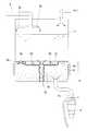
この発明に係るウォーターサーバーの一例である実施形態(以下、単に「このウォーターサーバー」と呼ぶ)を添付図面に基づいて説明する。図1、図2に示すように、このウォーターサーバーは、貯留水を冷却する冷水タンク1と、原水容器2から冷水タンク1に補給する水が通る水導入路3と、冷水タンク1から大気まで通じる冷水注出路4と、水導入路3から冷水タンク1に流入した水の下降を邪魔するバッフル5とを備えている。原水容器2の水は、水導入路3を経て冷水タンク1へ送られ、冷水タンク1に付設の熱交換器6で冷水タンク1内の貯留水が冷却され、ユーザの操作によって弁(図示省略)が開き、冷水タンク1で冷やされた水が冷水注出路4を経て大気に注出されるようになっている。 An embodiment (hereinafter simply referred to as “this water server”) as an example of a water server according to the present invention will be described with reference to the accompanying drawings. As shown in FIGS. 1 and 2, the water server includes a
冷水タンク1は、内側に貯留水を蓄えるタンク壁を外側の熱交換器6との間の熱交換で冷やすことにより、貯留水を冷却するようになっている。 The
原水容器2は、交換式の容器からなる。この原水容器2は、ウォーターサーバーの筐体の下部引き出しに着脱可能になっている。冷水タンク1に補給する水は、上水道から供給するようにしてもよい。 The
水導入路3は、原水容器2と接続され、ポンプ7によって原水容器2内の水を吸い上げ、冷水タンク1の所定の満水位よりも高い位置にある終端部3aから、冷水タンク1へシャワー状、又は液滴状で水を流入させるようになっている。原水容器2からの送水は、冷水タンク1内の水位が所定以下になったことを水位センサが検出した場合に実施されるようになっている。原水容器2は、筐体下部でなく、冷水タンク1の上方に配置し、水導入路3を短くして冷水タンク1へ重力送水するようにしてもよい。 The
冷水注出路4は、ユーザ操作で開閉切り換え可能な弁(図2中に隠れ線の公差で弁を模式的に示した)を含み、この弁の下流に、大気への注出口をもった流路からなる。 The cold
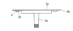
バッフル5は、冷水タンク1に着脱される部材になっている。バッフル5は、冷水タンク1の底面に対する固定箇所とされた縦軸部5aをもっている。バッフル5を外せば、冷水タンク下部hの内側を清掃することができる。水の下降を邪魔するバッフル5本来の機能部分は、縦軸部5aから最大外周部5bを成すように水平方向へ張り出た仕切板部5cのところのみである。ここで、「周」の概念は、水平面に対して同一高さ(同一地上高)となる一周を意味する。冷水タンク1の底面にバッフル5を固定しない場合、縦軸部5aを省略することもできる。仕切板部5cは、上下方向に貫通した部分をもたない板状になっている。最大外周部5bは、このウォーターサーバーの使用中において冷水タンク1の内周に最も近い部分を含む周囲であって、最大の周長を成しており、水の下降を邪魔する水平方向の限界位置となる。最大外周部5bは、このウォーターサーバーの使用中、冷水タンク1の内周に嵌合された状態を保てる耐水圧性をもっている。最大外周部5bと冷水タンク1の内周の嵌合構造に代えて、最大外周部5bと冷水タンク1の内周との間に全周に亘る隙間を設けてもよい。この隙間は、水導入路3から流入した水が真直ぐに達することができない狭い隙間にすればよい。この場合、その隙間からバッフル5上の水が穏やかに下降するようにし、熱交換器6に沿った冷水タンク1の内周部分に達するようにすることができる。 The
熱交換器6は、冷水タンク1の底部1aからバッフル5の最大外周部5bまでの高さになる冷水タンク下部に設けられている。ここで、「高さ」の概念は、水面高さを決める地上高をいう。冷水タンク1の底部1aは、冷水タンク1の中で高さの最も低い内壁部分のことをいう。図示例だと、冷水タンク1の底部1aは、冷水タンク1と冷水注出路4の境界になる弁が閉弁した状態における弁体の上流側表面といえる。冷水タンク下部になる高さ範囲hを、図2中に上下方向の両端矢線で示した。以下、冷水タンク1の高さ範囲hの部分を、「冷水タンク下部h」と呼ぶ。冷水タンク下部h内には、熱交換器6による冷却と、バッフル5の邪魔板性能とにより、バッフル5上の水温より低い低水温層が底部1a側から生じる。なお、図1、図2中においては、冷水タンク1の貯留水の水温が低いところ程に濃くなるドット模様を描いた。 The
冷水注出路4は、冷水タンク下部hの最下部となる底部1aに接続されているので、低水温層の水を注出することができる。冷水注出路4は、底部1aと同高さで冷水タンク1と接続する必要性はないが、低水温層の水を無駄なく供給するため、冷水タンク下部hの底部1aに近い側の高さで接続することが好ましい。 Since the cold
なお、このウォーターサーバーは、冷水タンク1から供給された水を加熱する温水タンク8と、バッフル5上から冷水タンク1内の貯留水を温水タンク8に供給する接続路9と、温水タンク8から大気まで通じる温水注出路10とを備えている。縦軸部5aの内部は、接続路9と冷水タンク1との境界になる弁9a(図2中に実線の公差で弁を模式的に示した)の組み込み部分になっている。低水温層より高温であるバッフル5上の水を接続路9から温水タンク8に供給するため、原水容器2からの送水系統を一系統にしつつ、温水タンク8による加熱を軽減することができる。熱交換器6をバッフル5の最大外周部5bより低い位置のみに設けることにより、温水タンク8に供給されるバッフル5上の水の冷却を避け、省エネルギー化を図ることができる。 The water server includes a
バッフル5の縦軸部5aの外周下部は、冷水タンク1の底面に形成された雌ねじにねじ込む雄ねじになっている。仕切板部5cの上面には、バッフル5のねじ回し作業用に掴み部5dが突き出ている。縦軸部5aは、温飲料の供給機能をもたないウォーターサーバーとしたり、別途のチューブ等で接続路9と仕切板部5cを連結可能としたりする場合、冷水タンク1の段部にバッフル5を載置したり、引っ掛けたりする着脱構造の採用により、バッフル5から省略することができる。 The lower part of the outer periphery of the
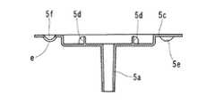
バッフル5のうち、最大外周部5bより内側に、水導入路3から流入した水をバッフル5上から冷水タンク下部hへ通す移流路5eが設けられている。図3〜図8に示すように、移流路5eは、上下方向に非貫通であって、水平方向に近い向きで冷水タンク下部hに水を放つ流路からなる。ここで、「放つ」とは、低水温層側へ向う流動を自由にすることを意味し、より具体的には、移流路5eによる水平方向及び下方向についての流線制御が以後不可能になることをいう。 In the
この移流路5eは、バッフル5の仕切板部5cの上面で部分的に下側へ凹む凹面5fと、この凹面5fの先端縁部eの上方に重なる厚み縁部5gとからなる。先端縁部eは、移流路5eを形成する流路内面の最先端部からなり、冷水タンク下部h内に水平方向及び下向きに臨んでいる。厚み縁部5gは、凹面5fを部分的に凹ませるために上面に生じた分断部分での厚み(上下方向)を成している縁部からなる。移流路5eの終端口は、凹面5fの先端縁部eと、厚み縁部5gとで形成され、バッフル5の側面のみに開放している。この凹面5fは、複数の曲面で構成され、先端縁部eから上流側に向って、水平面に対し上方に45°よりも小さい勾配部分を含んでいる。この勾配部分には、上方から下降する水を凹面5fの先端縁部eの凹底に向けて集める勾配も与えられている。バッフル5上から移流路5eへ下降した水は、図5、図9中に流線を矢線で模式的に示すように、上下方向に非貫通の凹面5fによって流線を水平方向に近い向きに曲げられてから、先端縁部eと厚み縁部5gとで形成された終端口に至り、水平方向に近い向きの流線で終端口から冷水タンク下部hへ放たれる。移流路5eから放たれた水の流線制御が以後不可能になるので、放たれた水の流線をできるだけ保つことが好ましい。このため、バッフル5は、移流路5eの終端口と同高さで対面する部分をもたない。凹面5fは、曲面からなるものに限定されず、上記の流線で放つことができる限り、テーパ面、平面、鉛直面等から適宜に構成することができる。 The
移流路5eから水平方向に近い向きで放たれた水は、下方向の速度成分に対して優性な水平方向の速度成分をもつので、図2に示す冷水タンク下部hを真直ぐに下降することはなく、下方向よりも水平方向に大きく流れる。このため、冷水タンク下部hの底部1a側から生じている低水温層と、移流路5eから放たれた水とが混ざるまでの移流距離は、下方向の流線で冷水タンク下部に放つ場合と比して延びる。したがって、このウォーターサーバーによれば、移流路5eから放たれた水が低水温層に混ざり難くすることができる。なお、この移流路5eは、移流路5eから放れた水の水平方向の速度成分を最大化するため、移流路5eの終端口が実質的に水平方向を向くように設定されている。 The water released in the direction close to the horizontal direction from the
移流路5eは、仕切板部5cと、ここに装着するバッフル構成部品とを組み合わせて形成することもできる。この場合、移流路5e内で複雑に屈曲する流路とすることができるので、移流路5eの終端口に至る水の勢いを弱めるのに好適である。 The
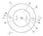
図3〜図8に示すように、バッフル5には、複数の移流路5eが設けられている。これら移流路5eの全ての終端口は、上下方向の共通軸を中心とする同一回り方向に向いている。図示例だと、縦軸部5aを前記共通軸に定めた同一の回り方向に向いている。各移流路5eから冷水タンク下部hに放たれた水は、互いに同一高さで正面衝突し得ず、特に図6中に流線を矢線で模式的に示すように、冷水タンク下部h内を穏やかに旋回しながら、図2に示す冷水タンク下部h内を下降し易くなるので、低水温層までの移流距離がより長くなり、低水温層により混ざり難くすることができる。 As shown in FIGS. 3 to 8, the
前記の旋回流を促進するため、これら移流路5eの全ての終端口は、同高さで冷水タンク1の円筒状の内周に臨むように設け、この円筒状の中心軸と前記の共通軸とを同軸にすることが好ましい。 In order to promote the swirl flow, all the end ports of the
図3〜図8に示すバッフル5は、移流路5eを二本だけ有し、共通軸回りに180°の回転対称性をもつ形状となっている(ただし、縦軸部5aの雄ねじを除く)。また、バッフル5は、一体に成型された単一部品になっている。凹面5f及び厚み縁部5gからなる移流路5eは、バッフル5を一体成型する場合に、バッフル5の上面を成型する上面側金型と、バッフル5の下面を成型する水平方向に分割された下面側金型とで、アンダーカットを作ることなく形成することができる。厚み縁部5gの下方に重なる凹面5fの先端縁部eは、二本の移流路5eの平行方向に分割された下面側金型で形成され、この下面側金型により、外周に雄ねじをもった縦軸部5aも成型することができる。バッフル5を形成する材料は、射出成型可能な合成樹脂になっているが、金属製や、プレス加工品のバッフルにしてもよい。なお、図4のA−A線は、バッフル5の最大外周部5bの直径線を含む。図4のB−B線は、移流路5eを鏡面対称に分割する鉛直平面を含む。 The
移流路5eの数や配置は、図示例に限定されない。例えば、冷水タンク1の内周とバッフル5の最大外周部5bとを嵌合する場合、移流路5eの数を増やし、所要の通水性を確保することができる。なお、旋回流の形成に伴う移流距離の延長に期待して、移流路5eの数を二本に留めつつ、各移流路5eの流路断面を大きくして所要の通水性を確保してもよい。この発明の技術的範囲は、上述の実施形態に限定されず、特許請求の範囲の記載に基く技術的思想の範囲内での全ての変更を含むものである。 The number and arrangement of
1 冷水タンク
1a 底部
h 冷水タンク下部
2 原水容器
3 水導入路
4 冷水注出路
5 バッフル
5a 縦軸部
5b 最大外周部
5c 仕切板部
5d 掴み部
5e 移流路
5f 凹面
5g 厚み縁部
e 先端縁部
6 熱交換器
DESCRIPTION OF
Claims (3)
Translated fromJapanese前記冷水タンク(1)の底部(1a)から前記バッフル(5)の最大外周部(5b)までの高さになる冷水タンク下部(h)内に、前記バッフル(5)上の水温より低い低水温層が生じ、前記冷水注出路(4)が前記低水温層の水を注出するように設けられており、
前記バッフル(5)のうち、最大外周部(5b)より内側に、前記流入した水をバッフル(5)上から前記冷水タンク下部(h)へ通す移流路(5e)が設けられているウォーターサーバーにおいて、
前記移流路(5e)が、上下方向に非貫通であって、水平方向に近い向きで前記冷水タンク下部(h)に水を放つ流路からなることを特徴とするウォーターサーバー。A cold water tank (1) for cooling the stored water, a water introduction path (3) through which water to be replenished to the cold water tank (1) passes, a cold water discharge path (4) leading from the cold water tank (1) to the atmosphere, A baffle (5) for interfering with the descent of water flowing into the cold water tank (1) from the water introduction path (3),
In the lower part (h) of the cold water tank, which is at a height from the bottom (1a) of the cold water tank (1) to the maximum outer peripheral part (5b) of the baffle (5), the temperature is lower than the water temperature on the baffle (5). A water temperature layer is formed, and the cold water discharge channel (4) is provided to discharge water of the low water temperature layer,
A water server provided with a transfer passage (5e) for passing the inflowing water from above the baffle (5) to the lower part (h) of the cold water tank inside the maximum outer peripheral portion (5b) of the baffle (5). In
The water server according to claim 1, wherein the transfer channel (5e) is a channel that is non-penetrating in the vertical direction and discharges water to the lower part (h) of the cold water tank in a direction close to the horizontal direction.
Priority Applications (7)
| Application Number | Priority Date | Filing Date | Title |
|---|---|---|---|
| JP2012001291AJP5529174B2 (en) | 2012-01-06 | 2012-01-06 | Water server |
| TW101112833ATW201328960A (en) | 2012-01-06 | 2012-04-11 | Water server |
| KR20147021313AKR20140110022A (en) | 2012-01-06 | 2012-07-02 | Water server |
| CN201280065607.7ACN104080727A (en) | 2012-01-06 | 2012-07-02 | Water server |
| US14/370,070US9315371B2 (en) | 2012-01-06 | 2012-07-02 | Water dispenser |
| PCT/JP2012/066860WO2013103026A1 (en) | 2012-01-06 | 2012-07-02 | Water server |
| EP12864302.0AEP2801547B1 (en) | 2012-01-06 | 2012-07-02 | Water server |
Applications Claiming Priority (1)
| Application Number | Priority Date | Filing Date | Title |
|---|---|---|---|
| JP2012001291AJP5529174B2 (en) | 2012-01-06 | 2012-01-06 | Water server |
Publications (2)
| Publication Number | Publication Date |
|---|---|
| JP2013141982A JP2013141982A (en) | 2013-07-22 |
| JP5529174B2true JP5529174B2 (en) | 2014-06-25 |
Family
ID=48745096
Family Applications (1)
| Application Number | Title | Priority Date | Filing Date |
|---|---|---|---|
| JP2012001291AActiveJP5529174B2 (en) | 2012-01-06 | 2012-01-06 | Water server |
Country Status (7)
| Country | Link |
|---|---|
| US (1) | US9315371B2 (en) |
| EP (1) | EP2801547B1 (en) |
| JP (1) | JP5529174B2 (en) |
| KR (1) | KR20140110022A (en) |
| CN (1) | CN104080727A (en) |
| TW (1) | TW201328960A (en) |
| WO (1) | WO2013103026A1 (en) |
Families Citing this family (3)
| Publication number | Priority date | Publication date | Assignee | Title |
|---|---|---|---|---|
| CN108317804B (en)* | 2017-12-23 | 2020-06-23 | 青岛海尔股份有限公司 | Water storage device and refrigerator with same |
| CN108278849B (en)* | 2017-12-23 | 2020-06-23 | 青岛海尔股份有限公司 | A water storage device and a refrigerator with the same |
| JP7163164B2 (en)* | 2018-12-11 | 2022-10-31 | 矢崎エナジーシステム株式会社 | drinking water supply |
Family Cites Families (25)
| Publication number | Priority date | Publication date | Assignee | Title |
|---|---|---|---|---|
| US3088289A (en)* | 1962-02-19 | 1963-05-07 | Sparkletts Drinking Water Corp | Water cooler |
| US3250433A (en)* | 1964-08-21 | 1966-05-10 | Allen Electronics Inc | Liquid dispensing unit |
| US4597509A (en)* | 1984-11-13 | 1986-07-01 | Mckesson Corporation | Drinking water dispensing unit and method |
| US4651862A (en)* | 1985-06-10 | 1987-03-24 | Greenfield Jr Irving E | Dual temperature beverage dispenser with removable operating module |
| JPS63190880A (en) | 1986-09-09 | 1988-08-08 | Nippon Tokushu Noyaku Seizo Kk | Novel n-benzothiazolyl-amides and insecticide |
| JPS63190880U (en)* | 1987-05-27 | 1988-12-08 | ||
| US4958747A (en)* | 1988-08-15 | 1990-09-25 | Sheets Kerney T | Bottled water dispenser |
| JPH04135497A (en) | 1990-09-28 | 1992-05-08 | Toshiba Corp | Gene detection method using hydrophobic nucleic acid probe |
| JP2525741Y2 (en)* | 1991-06-06 | 1997-02-12 | 横浜ゴム株式会社 | Partition plate structure of cold water tank in drinking water dispenser |
| GB9306254D0 (en)* | 1993-03-25 | 1993-05-19 | Dolphin Water Shops Ltd | Instant hot water dispenser |
| US5667103A (en)* | 1995-03-10 | 1997-09-16 | Elkay Manufacturing Company | Liquid dispenser with readily removable reservoir and adaptor permitting use with various dispensers |
| CN2251953Y (en)* | 1995-11-08 | 1997-04-16 | 上海贺众饮水设备有限公司 | Microcomputer controlled bottled type drinking machine |
| US5862669A (en)* | 1996-02-15 | 1999-01-26 | Springwell Dispensers, Inc. | Thermoelectric water chiller |
| JP2000085893A (en)* | 1998-09-17 | 2000-03-28 | Fuji Electric Co Ltd | Drinking water dispenser |
| JP3689312B2 (en)* | 2000-06-01 | 2005-08-31 | ホシザキ電機株式会社 | Guide member for storage tank in beverage dispenser |
| JP2003012092A (en) | 2001-06-29 | 2003-01-15 | Hoshizaki Electric Co Ltd | Beverage dispenser |
| US6912867B2 (en) | 2003-05-13 | 2005-07-05 | Oasis Corporation | Combined water cooler and refrigerator unit |
| US7422684B1 (en)* | 2003-10-16 | 2008-09-09 | S.I.P. Technologies, L.L.C. | Method and apparatus for sanitizing water dispensed from a water dispenser having a reservoir |
| JP4714048B2 (en) | 2006-03-10 | 2011-06-29 | 株式会社 エスト | Cold water generator and cold / hot water server using the same |
| CN101273843B (en)* | 2007-03-26 | 2011-08-17 | 周奇迪 | Drinking machine with the cold liner detachable and the cold liner thereof |
| JP4253036B1 (en) | 2008-08-27 | 2009-04-08 | 株式会社コスモライフ | Beverage dispenser |
| WO2010023967A1 (en) | 2008-08-27 | 2010-03-04 | 株式会社コスモライフ | Beverage dispenser |
| KR100900300B1 (en)* | 2009-02-23 | 2009-06-02 | 주식회사 크로버 | Water distributor |
| CN201492284U (en)* | 2009-09-07 | 2010-06-02 | 依莱克顿(宁波)电器科技有限公司 | Water dispenser with hot-water sterilization function |
| JP5559722B2 (en) | 2011-02-18 | 2014-07-23 | パーパス株式会社 | Drinking water supply equipment |
- 2012
- 2012-01-06JPJP2012001291Apatent/JP5529174B2/enactiveActive
- 2012-04-11TWTW101112833Apatent/TW201328960A/enunknown
- 2012-07-02EPEP12864302.0Apatent/EP2801547B1/ennot_activeNot-in-force
- 2012-07-02KRKR20147021313Apatent/KR20140110022A/ennot_activeWithdrawn
- 2012-07-02USUS14/370,070patent/US9315371B2/ennot_activeExpired - Fee Related
- 2012-07-02CNCN201280065607.7Apatent/CN104080727A/enactivePending
- 2012-07-02WOPCT/JP2012/066860patent/WO2013103026A1/enactiveApplication Filing
Also Published As
| Publication number | Publication date |
|---|---|
| EP2801547A4 (en) | 2015-06-17 |
| TW201328960A (en) | 2013-07-16 |
| WO2013103026A1 (en) | 2013-07-11 |
| US9315371B2 (en) | 2016-04-19 |
| KR20140110022A (en) | 2014-09-16 |
| JP2013141982A (en) | 2013-07-22 |
| EP2801547A1 (en) | 2014-11-12 |
| EP2801547B1 (en) | 2016-09-14 |
| US20140339261A1 (en) | 2014-11-20 |
| CN104080727A (en) | 2014-10-01 |
Similar Documents
| Publication | Publication Date | Title |
|---|---|---|
| EP1840484B1 (en) | Apparatus and method for delivering water into a water heater | |
| JP5529174B2 (en) | Water server | |
| US20110173744A1 (en) | Sanitary washing apparatus | |
| US20070227468A1 (en) | Apparatus and method for introducing and drawing water in a water heater | |
| EP2159838A3 (en) | Liquid-cooled-type cooling device | |
| CN103386468A (en) | Die-cast component and method for producing mold-cast component | |
| WO2011106978A1 (en) | Auxiliary water tank for engine cooling system | |
| JP7077669B2 (en) | Bathtub water circulation type spouting device or bathtub device equipped with it | |
| CN107848026A (en) | Gate system for die casting molds | |
| CN201086127Y (en) | ladle | |
| CN106196068B (en) | Air distribution disk, burner, gas-cooker and oven | |
| EP3106636B1 (en) | Blow-by heater | |
| JP2015110434A (en) | Drinking water dispenser | |
| CN205324693U (en) | Be applied to die casting die's cooling body | |
| CN104939685A (en) | Water outlet device for water dispenser heater | |
| JP2011178408A (en) | Drinking water supplying apparatus | |
| CN204318469U (en) | A kind of thin-walled drinker cold liner | |
| CN111014632A (en) | Casting system for tin bars | |
| JP6410325B2 (en) | Fuel oil transfer device | |
| CN109222660A (en) | Hot tank and water dispenser | |
| CN208601931U (en) | A kind of Simple detachable timesharing cooling device | |
| CN107110621A (en) | Including for the heat exchanger by gas phase and liquid phase separation and for the separative element that distributes liquid phase, especially block shell heat exchanger | |
| JP2007307593A (en) | Cooling structure for metallic mold | |
| CN221060406U (en) | Liquid outlet structure and beverage machine | |
| CN218505092U (en) | Car roof armrest processing die |
Legal Events
| Date | Code | Title | Description |
|---|---|---|---|
| A621 | Written request for application examination | Free format text:JAPANESE INTERMEDIATE CODE: A621 Effective date:20140214 | |
| A871 | Explanation of circumstances concerning accelerated examination | Free format text:JAPANESE INTERMEDIATE CODE: A871 Effective date:20140214 | |
| RD03 | Notification of appointment of power of attorney | Free format text:JAPANESE INTERMEDIATE CODE: A7423 Effective date:20140214 | |
| TRDD | Decision of grant or rejection written | ||
| A975 | Report on accelerated examination | Free format text:JAPANESE INTERMEDIATE CODE: A971005 Effective date:20140317 | |
| A01 | Written decision to grant a patent or to grant a registration (utility model) | Free format text:JAPANESE INTERMEDIATE CODE: A01 Effective date:20140325 | |
| A61 | First payment of annual fees (during grant procedure) | Free format text:JAPANESE INTERMEDIATE CODE: A61 Effective date:20140416 | |
| R150 | Certificate of patent or registration of utility model | Ref document number:5529174 Country of ref document:JP Free format text:JAPANESE INTERMEDIATE CODE: R150 | |
| S111 | Request for change of ownership or part of ownership | Free format text:JAPANESE INTERMEDIATE CODE: R313111 | |
| R350 | Written notification of registration of transfer | Free format text:JAPANESE INTERMEDIATE CODE: R350 | |
| R250 | Receipt of annual fees | Free format text:JAPANESE INTERMEDIATE CODE: R250 | |
| R250 | Receipt of annual fees | Free format text:JAPANESE INTERMEDIATE CODE: R250 | |
| R250 | Receipt of annual fees | Free format text:JAPANESE INTERMEDIATE CODE: R250 | |
| R250 | Receipt of annual fees | Free format text:JAPANESE INTERMEDIATE CODE: R250 | |
| R250 | Receipt of annual fees | Free format text:JAPANESE INTERMEDIATE CODE: R250 | |
| R250 | Receipt of annual fees | Free format text:JAPANESE INTERMEDIATE CODE: R250 | |
| R250 | Receipt of annual fees | Free format text:JAPANESE INTERMEDIATE CODE: R250 | |
| R250 | Receipt of annual fees | Free format text:JAPANESE INTERMEDIATE CODE: R250 | |
| R250 | Receipt of annual fees | Free format text:JAPANESE INTERMEDIATE CODE: R250 |