JP5523576B2 - Elevator control panel - Google Patents
Elevator control panelDownload PDFInfo
- Publication number
- JP5523576B2 JP5523576B2JP2012539512AJP2012539512AJP5523576B2JP 5523576 B2JP5523576 B2JP 5523576B2JP 2012539512 AJP2012539512 AJP 2012539512AJP 2012539512 AJP2012539512 AJP 2012539512AJP 5523576 B2JP5523576 B2JP 5523576B2
- Authority
- JP
- Japan
- Prior art keywords
- target device
- maintenance
- maintenance target
- control panel
- rotation
- Prior art date
- Legal status (The legal status is an assumption and is not a legal conclusion. Google has not performed a legal analysis and makes no representation as to the accuracy of the status listed.)
- Active
Links
Images


Classifications
- B—PERFORMING OPERATIONS; TRANSPORTING
- B66—HOISTING; LIFTING; HAULING
- B66B—ELEVATORS; ESCALATORS OR MOVING WALKWAYS
- B66B5/00—Applications of checking, fault-correcting, or safety devices in elevators
- B66B5/0087—Devices facilitating maintenance, repair or inspection tasks
- B—PERFORMING OPERATIONS; TRANSPORTING
- B66—HOISTING; LIFTING; HAULING
- B66B—ELEVATORS; ESCALATORS OR MOVING WALKWAYS
- B66B1/00—Control systems of elevators in general
- B66B1/34—Details, e.g. call counting devices, data transmission from car to control system, devices giving information to the control system
- B—PERFORMING OPERATIONS; TRANSPORTING
- B66—HOISTING; LIFTING; HAULING
- B66B—ELEVATORS; ESCALATORS OR MOVING WALKWAYS
- B66B5/00—Applications of checking, fault-correcting, or safety devices in elevators
Landscapes
- Engineering & Computer Science (AREA)
- Automation & Control Theory (AREA)
- Computer Networks & Wireless Communication (AREA)
- Elevator Control (AREA)
- Maintenance And Inspection Apparatuses For Elevators (AREA)
Description
Translated fromJapaneseこの発明は、昇降路内に設置されるエレベータの制御盤に関するものである。 The present invention relates to an elevator control panel installed in a hoistway.
従来、昇降路内に設置された制御盤に対してかご上からの保守点検作業を容易に行うために、複数の部分制御盤を互いに連結することにより制御盤を折りたたみ可能としたエレベータが提案されている。この従来のエレベータでは、通常運転時に、制御盤が折りたたまれた状態で昇降路内の上端部に保持され、保守点検時に、制御盤の折りたたみ状態を解除して各部分制御盤が一列に吊り下がるようになっている。保守点検時には、かごを上下に移動させることにより、かご上の作業者が各部分制御盤の位置に容易に達することができる(特許文献1参照)。 Conventionally, an elevator has been proposed in which a control panel can be folded by connecting a plurality of partial control panels to each other in order to easily perform maintenance and inspection work on the control panel installed in the hoistway. ing. In this conventional elevator, during normal operation, the control panel is folded and held at the upper end of the hoistway, and during maintenance, the control panel is released from the folded state and each partial control panel is suspended in a line. It is like that. At the time of maintenance and inspection, the worker on the car can easily reach the position of each partial control panel by moving the car up and down (see Patent Document 1).
しかし、制御盤が昇降路内のピット部に設置されている場合には、作業者がかご上に乗って保守点検作業を行うことができないので、昇降路内の床に足場台(例えば脚立等)を置いて、足場台に乗った作業者が制御盤に対して保守点検作業を行うこととなる。 However, when the control panel is installed in the pit part in the hoistway, the operator cannot get on the car to perform maintenance and inspection work. ), And the worker on the scaffolding will perform maintenance and inspection work on the control panel.
ここで、昇降路内には、かごや釣合おもり等、複数の機器が配置されているので、昇降路内で制御盤を配置するスペースを水平方向について広げるには限界がある。従って、制御盤の容積を確保するためには、制御盤の高さ寸法を大きくする必要がある。 Here, since a plurality of devices such as a car and a counterweight are arranged in the hoistway, there is a limit in expanding the space for arranging the control panel in the hoistway in the horizontal direction. Therefore, in order to ensure the volume of the control panel, it is necessary to increase the height dimension of the control panel.
しかし、足場台に乗っても作業者が届かないような高い位置(例えば、足場台の上面から1800mmの高さよりも上方の位置)に保守点検の対象となる機器(保守対象機器)を配置しても、作業者は保守対象機器の保守点検作業を行うことができない。従って、従来、作業者が届かないような高い位置には、保守点検の対象とはならない故障しにくい機器(例えば回生抵抗等)のみしか配置することができず、保守対象機器を設置する位置が制限されてしまう。 However, the equipment (maintenance target equipment) that is subject to maintenance inspection is placed at a high position (for example, a position higher than the height of 1800 mm from the top surface of the scaffold base) so that the worker does not reach even if it gets on the scaffold base. However, the operator cannot perform maintenance and inspection work on the maintenance target device. Therefore, conventionally, only high-resistance devices that are not subject to maintenance and inspection (for example, regenerative resistors) can be placed at high positions where workers cannot reach. It will be restricted.
この発明は、上記のような課題を解決するためになされたものであり、保守対象機器のレイアウトの自由度を向上させることができるエレベータの制御盤を得ることを目的とする。 The present invention has been made to solve the above-described problems, and an object of the present invention is to obtain an elevator control panel that can improve the degree of freedom in layout of maintenance target devices.
この発明によるエレベータの制御盤は、昇降路内に配置された支持体、支持体に設けられた回動軸を中心に回動可能な回動部材、回動部材に設けられ、回動部材の回動により、回動軸よりも上方に位置する通常位置と、回動軸よりも下方に位置する点検位置との間で支持体に対して変位される保守対象機器、及び回動部材から下方へ延び、外部からの引き下げ力を受けることにより、保守対象機器が通常位置から点検位置へ変位する方向へ回動部材を回動させる操作部材を備えている。 An elevator control panel according to the present invention includes a support disposed in a hoistway, a rotation member rotatable about a rotation shaft provided on the support, and a rotation member. The maintenance target device that is displaced with respect to the support between the normal position positioned above the rotation axis and the inspection position positioned below the rotation axis by the rotation, and the rotation member And an operation member that rotates the rotation member in a direction in which the maintenance target device is displaced from the normal position to the inspection position by receiving a pulling force from the outside.
この発明によるエレベータの制御盤では、支持体に設けられた回動軸を中心に回動可能な回動部材に保守対象機器が設けられ、回動部材の回動により、回動軸よりも上方に位置する通常位置と、回動軸よりも下方に位置する点検位置との間で保守対象機器が変位されるので、通常運転時には、作業者の届かないアクセス不可領域に保守対象機器を配置しておき、保守点検時にのみ、作業者による保守点検が可能なアクセス可能領域へ保守対象機器を変位させることができる。これにより、制御盤の設置スペースを水平方向について広げずに、保守対象機器のレイアウトの自由度を向上させることができる。 In the elevator control panel according to the present invention, the maintenance target device is provided on the rotating member that is rotatable about the rotating shaft provided on the support body, and the rotating member rotates to move upward from the rotating shaft. Because the maintenance target device is displaced between the normal position located at the position and the inspection position located below the rotation axis, the maintenance target device is placed in an inaccessible area where the worker cannot reach during normal operation. In addition, the maintenance target device can be displaced to an accessible area where maintenance inspection can be performed by an operator only during maintenance inspection. Thereby, the freedom degree of the layout of a maintenance object apparatus can be improved, without expanding the installation space of a control panel about a horizontal direction.
以下、この発明の好適な実施の形態について図面を参照して説明する。
実施の形態1.
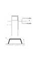
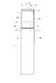
図1は、この発明の実施の形態1によるエレベータの制御盤が昇降路内に設置されている状態を示す正面図である。図において、かご及び釣合おもり(いずれも図示せず)が昇降される昇降路内のピット部には、エレベータの運転を制御する制御盤1が設置されている。この例では、制御盤1は、機械室が設けられていない機械室レスエレベータの制御盤とされている。制御盤1は、水平方向についてかご及び釣合おもりを避けて配置されている。Preferred embodiments of the present invention will be described below with reference to the drawings.
FIG. 1 is a front view showing a state in which an elevator control panel according to
制御盤1に対する保守点検作業を行うときには、足場台2が昇降路のピット面(床面)3に置かれる。作業者は、ピット面3に置かれた足場台2の上面に乗った状態で、制御盤1に対して保守点検作業を行う。 When maintenance inspection work is performed on the
ピット面3から所定の高さだけ上方へ離れた位置には、足場台2に乗った状態で作業者がアクセス可能な高さの限界(即ち、作業者による保守点検作業が可能な高さの限界)を示す作業限界レベルAが設定されている。この例では、ピット面3上に置かれた足場台2の上面から1800mmの高さの位置に作業限界レベルAが設定されている。従って、作業限界レベルAよりも上方の領域は、作業者がアクセス不可能なアクセス不可領域とされ、作業限界レベルAよりも下方の領域は、作業者がアクセス可能なアクセス可能領域とされている。 At a position away from the pit surface 3 by a predetermined height, a height limit that is accessible to the worker while riding on the scaffolding platform 2 (that is, a height at which the worker can perform maintenance and inspection work). An operation limit level A indicating (limit) is set. In this example, the work limit level A is set at a position of 1800 mm from the upper surface of the
制御盤1は、一部がアクセス可能領域に配置され、残りの一部がアクセス不可領域に配置された状態で、昇降路内に立てて設置されている。従って、保守点検作業を行う作業者は、制御盤1のうち、アクセス不可領域に配置された部分にアクセスすることができず、アクセス可能領域に配置された部分にのみアクセス可能になっている。 The
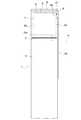
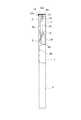
図2は、図1のエレベータの制御盤1を示す正面図である。また、図3は、図2のエレベータの制御盤1を示す一部破断側面図である。図において、制御盤1は、昇降路内に立てて配置された筐体(支持体)4と、筐体4に設けられた回動軸5を中心に回動可能な回動パネル(回動部材)6と、回動パネル6に設けられた保守対象機器7と、回動パネル6から下方へ延びる操作レバー(操作部材)8とを有している。 FIG. 2 is a front view showing the
筐体4は、一部(上部)がアクセス不可領域に配置され、残りの一部がアクセス可能領域に配置されている。筐体4の正面には、開口部9が設けられている。開口部9は、アクセス不可領域に位置している。この例では、図2に示すように、開口部9の形状が矩形状となっている。 A part (upper part) of the
回動軸5は、開口部9の下縁部に設けられている。また、回動軸5は、筐体4の幅方向に沿って水平に配置されている。この例では、回動軸5が作業限界レベルAよりも上方に配置されている。 The
回動パネル6は、図3に示すように、回動軸5を中心として回動されることにより、開口部9を塞ぐ閉塞位置(図3の実線)と、閉塞位置よりも下方に位置し、開口部9を開放する開放位置との間で変位される。また、回動パネル6は、保守対象機器7が取り付けられた機器取付板(機器取付部)6aと、機器取付板6aの端部から突出し、回動軸5に回動可能に接続された接続板(接続部)6bと、機器取付板6aの両側部から回動軸5に垂直な方向へ突出する一対の側板(突出部)6cとを有している。この例では、機器取付板6a、接続板6b及び各側板6cが一枚の板を曲げて一体に形成されている。 As shown in FIG. 3, the
接続板6bは、機器取付板6aを含む平面に交差する方向へ機器取付板6aの端部から突出している。この例では、接続板6bが機器取付板6aに対して垂直になっている。 The
機器取付板6aは、回動パネル6が閉塞位置にあるときに、回動軸5よりも筐体4の内側に配置される。回動パネル6は、機器取付板6aと回動軸5との距離が接続板6bにより一定に保たれながら、回動軸5を中心に回動される。これにより、回動パネル6が閉塞位置と開放位置との間を変位されるときには、筐体4に対する機器取付板6aの干渉が回避される。 The
各側板6cは、回動パネル6が閉塞位置にあるときに、筐体4の背面に向かって機器取付板6aから突出している。各側板6cのうち、いずれか一方には、回動軸5に平行なピン10が固定されている。ピン10は、回動パネル6の外側へ側板6cから突出している。 Each
保守対象機器7は、保守点検の対象となる機器である。即ち、保守対象機器7は、エレベータの製品寿命よりも寿命の短い機器で、保守点検時に確認、操作、調整又は整備等が必要な機器である。保守対象機器7としては、例えば半導体を搭載したインバータ(電子部品搭載機器)等が挙げられる。なお、筐体4内には、保守対象機器7の他に、複数の機器が収容されている。 The
保守対象機器7は、各側板6c間に配置された状態で機器取付板6aに取り付けられている。また、保守対象機器7は、回動パネル6と一体に変位される。保守対象機器7は、回動パネル6の回動軸5を中心とした回動により、回動軸5よりも上方に位置する通常位置(図3の実線)と、回動軸5よりも下方に位置する点検位置との間で筐体4に対して変位される。即ち、保守対象機器7は、回動パネル6が閉塞位置へ変位されることにより通常位置へ変位され、回動パネル6が開放位置へ変位されることにより点検位置へ変位される。 The
保守対象機器7は、通常位置に達することによりアクセス不可領域に配置され、点検位置に達することによりアクセス可能領域に配置される。また、保守対象機器7は、通常位置にあるときに筐体4内に収容され、点検位置にあるときに筐体4外に露出される。保守対象機器7に対する保守点検作業は、保守対象機器7が通常位置から点検位置へ変位されることにより可能になる。なお、保守対象機器7には、電源線や信号線等の配線が接続されている。保守対象機器7に接続された配線は、保守対象機器7の変位に伴って曲げ可能になっている。 The
操作レバー8は、ピン10に変位可能に取り付けられたレバー取付部8aと、レバー取付部8aに固定され、所定の長さを持つ操作棒8bとを有している。 The
レバー取付部8aには、図3に示すように、操作棒8bに沿った長穴11が設けられている。長穴11には、ピン10が挿入されている。操作レバー8は、長穴11にピン10が挿入された状態でピン10に保持されている。ピン10は、長穴11内を長穴11の長径方向に沿って変位可能になっている。従って、操作レバー8は、ピン10が長穴11内を変位される範囲内でピン10に対して変位可能になっている。レバー取付部8aには、操作棒8bの上端部が固定されている。操作棒8bの下端部は、アクセス可能領域に達している。 As shown in FIG. 3, the
筐体4の上端部には、保守対象機器7を通常位置に保持するためのフック12が設けられている。フック12は、開口部9の上方で筐体4の正面から水平に突出する板状の水平固定部12aと、水平固定部12aの先端部から下方へ突出する板状の係合部12bとを有している。フック12は、回動パネル6及び保守対象機器7が筐体4に対して変位される範囲を避けて配置されている。 A
図4は、図2のエレベータの制御盤1の要部を示す正面図である。また、図5は図4の操作レバー8が係合位置にあるときの制御盤1の要部を示す側面図、図6は図4の操作レバー8が解除位置にあるときの制御盤1の要部を示す側面図である。図において、操作レバー8は、回動パネル6が閉塞位置にあるときに(即ち、保守対象機器7が通常位置にあるときに)、フック12に係合する係合位置(図5)と、フック12との係合が外れる解除位置(図6)との間で回動パネル6に対して変位される。解除位置は、係合位置よりも下方の位置とされている。通常位置と点検位置との間での操作レバー8の変位は、ピン10に対するレバー取付部8aの変位により行われる。 FIG. 4 is a front view showing a main part of the
閉塞位置にあるときの回動パネル6は、操作レバー8が係合位置に変位されて操作レバー8とフック12とが係合されることにより、開放位置への回動が阻止される。即ち、保守対象機器7は、操作レバー8がフック12に係合されることにより、通常位置に保持される。また、閉塞位置にあるときの回動パネル6は、操作レバー8が解除位置に変位されて操作レバー8とフック12との係合が外れることにより、開放位置へ回動可能になる。即ち、保守対象機器7は、操作レバー8とフック12との係合が外れることにより、通常位置から点検位置へ変位可能になる。 When the
筐体4の外側面には、操作レバー8を係合位置に保持する保持用ねじ(保持装置)13が設けられる。保持用ねじ13としては、例えば手でつまみながら回すことができるつまみねじ等が用いられている。保持用ねじ13が設けられる位置は、アクセス可能領域とされている。操作レバー8(操作棒8b)の下端部には、図6に示すように、保持用ねじ13が通されるねじ通し穴14が設けられている。操作レバー8は、ねじ通し穴14に通された保持用ねじ13が筐体4の外側面に設けられたねじ穴(図示せず)に螺合されることにより、係合位置に保持される。 A holding screw (holding device) 13 that holds the
操作レバー8は、保持用ねじ13による保持が解除された状態で外部からの引き下げ力を受けることにより、解除位置に変位されるとともに、閉塞位置から開放位置(即ち、保守対象機器7が通常位置から点検位置へ変位する方向)へ回動パネル6を回動させる。 The
次に、制御盤1に搭載された保守対象機器7の保守点検作業を行うときの手順について説明する。保守点検作業が行われない通常運転時には、回動パネル6が閉塞位置に変位されていて、保守対象機器7が筐体4内に収容されている。また、通常運転時には、回動パネル6が開放位置に変位されないように、操作レバー8とフック12とが互いに係合された状態で操作レバー8が保持用ねじ13により筐体4に保持されている。このときには、保守対象機器7は、作業者の届かないアクセス不可領域に配置されている。 Next, a procedure for performing maintenance inspection work on the
保守対象機器7の保守点検時には、まずピット面3に足場台2が置かれる。この後、作業者が足場台2に乗って保持用ねじ13を筐体4から外す。これにより、操作レバー8が自重で下方へ変位され、操作レバー8とフック12との係合が外れる。 At the time of maintenance and inspection of the
この後、作業者が操作レバー8を引き下げながら、回動軸5を中心に回動パネル6を回動させる。これにより、保守対象機器7は、通常位置から点検位置へ変位され、アクセス可能領域に達する。 Thereafter, the operator rotates the
この後、作業者が保守対象機器7に対して保守点検を行う。この後、上記と逆の手順により、回動パネル6を閉塞位置に戻し、保持用ねじ13で操作レバー8を筐体4に留める。これにより、保守対象機器7の保守点検作業が終了する。 Thereafter, the operator performs maintenance inspection on the
このようなエレベータの制御盤1では、筐体4に設けられた回動軸5を中心に回動可能な回動パネル6に保守対象機器7が設けられ、回動パネル6の回動により、回動軸5よりも上方に位置する通常位置と、回動軸5よりも下方に位置する点検位置との間で保守対象機器7が変位されるので、通常運転時には、作業者の届かないアクセス不可領域に保守対象機器7を配置しておき、保守点検時にのみ、作業者による保守点検が可能なアクセス可能領域へ保守対象機器7を変位させることができる。これにより、制御盤1の設置スペースを水平方向について広げずに、保守対象機器7のレイアウトの自由度を向上させることができる。 In such an
また、回動パネル6から下方へ延びる操作レバー8は、保守対象機器7が通常位置にあるときに、フック12に係合する係合位置と、フック12との係合が外れる解除位置との間で回動パネル6に対して変位可能になっているので、回動パネル6を回動させるための手段と、保守対象機器7を通常位置に保持する手段とを操作レバー8で兼用することができる。従って、部品点数を少なくすることができ、コストの低減を図ることができる。 Further, the
また、回動パネル6は、保守対象機器7が取り付けられる機器取付板6aを有しており、機器取付板6aは、保守対象機器7が通常位置にあるときに回動軸5よりも筐体4の内側に配置されるので、機器取付板6aと回動軸5との距離を一定に保ちながら、回動パネル6を閉塞位置と開放位置との間で変位させることができる。これにより、回動パネル6が変位されるときの筐体4に対する機器取付板6aの干渉を避けることができる。従って、保守対象機器7の保守点検作業をさらに容易に行うことができる。 The
なお、上記の例では、操作レバー8を係合位置に保持する保持装置が保持用ねじ13とされているが、これに限定されない。例えば、筐体4に対して操作レバー8の操作棒8bを押さえる板ばねを保持装置として筐体4に設けて、筐体4と板ばねとの間で操作棒8bを把持することにより、操作レバー8を係合位置に保持するようにしてもよい。また、操作棒8bに設けられた切欠部に嵌る突起を保持装置として筐体4に設けて、操作棒8bの切欠部を突起に嵌めることにより操作レバー8を係合位置に保持するようにしてもよい。 In the above example, the holding device that holds the
実施の形態2.
図7は、この発明の実施の形態2によるエレベータの制御盤1において操作レバー8とフック21とが係合されているときの状態を示す要部正面図である。また、図8は、図7のエレベータの制御盤1を示す要部側面図である。さらに、図9は図7のエレベータの制御盤1において操作レバー8とフック21との係合が外れているときの状態を示す要部正面図、図10は図9のエレベータの制御盤1を示す要部側面図である。さらにまた、図11は図9のエレベータの制御盤1において保守対象機器7が点検位置に変位されている状態を示す要部正面図、図12は図11のエレベータの制御盤1を示す要部側面図である。
FIG. 7 is a front view of an essential part showing a state in which the
図において、筐体4の正面には、フック21が設けられている。フック21は、アクセス不可領域で開口部9に隣接して配置されている。また、フック21は、筐体4の正面から筐体4外へ水平に突出する受け部21aと、受け部21aの先端部から上方へ突出する係合部21bとを有している。従って、筐体4と係合部21bとの間には、所定の隙間が形成されている。 In the figure, a
操作レバー8のレバー取付部8aには、フック21が通されるフック通し穴22が設けられている。フック通し穴22の大きさは、筐体4を正面から見たときに、フック通し穴22内に係合部21bの全体が収まる大きさとされている。 The
操作レバー8は、回動パネル6が閉塞位置にあるときに(即ち、保守対象機器7が通常位置にあるときに)、フック21に係合する係合位置(図7及び図8)と、フック21との係合が外れる解除位置(図9及び図10)との間で回動パネル6に対して変位可能になっている。係合位置は、解除位置よりも下方に位置している。 The
操作レバー8が解除位置にあるときには、筐体4を正面から見ると、フック通し穴22内にフック21の全体が収まっている。操作レバー8が係合位置にあるときには、筐体4を正面から見ると、フック通し穴22がフック21に対して下方へずれている。 When the
操作レバー8がフック21に係合されている状態では、回動パネル6が閉塞位置に保持され、保守対象機器7が通常位置に保持される。操作レバー8とフック21との係合が外れることにより、回動パネル6が閉塞位置から開放位置へ変位可能になり、保守対象機器7が通常位置から点検位置へ変位可能になる。 In a state where the
なお、この例では、実施の形態1の保持用ねじ13は設けられていない。他の構成は実施の形態1と同様である。 In this example, the holding
保守対象機器7の保守点検作業を行うときの手順については、操作レバー8とフック21との係合を外す手順と、操作レバー8をフック21に係合させる手順とを除き、実施の形態1と同様である。 The procedure for performing maintenance and inspection work on the
操作レバー8とフック21との係合を外すときには、まず操作棒8bを上方へ押し上げて操作レバー8を係合位置から解除位置へ変位させる。この後、操作レバー8を筐体4の正面から手前に引きながら、回動パネル6を回動させる。これにより、係合部22bがフック通し穴22を通過し、回動パネル6が開放位置へ変位される。 When disengaging the
操作レバー8をフック21に係合させるときには、まず操作レバー8を解除位置に変位させた状態で、回動パネル6を開放位置から閉塞位置へ変位させる。このとき、係合部22bがフック通し穴22を通過する。回動パネル6が閉塞位置に達した後、操作棒8bを引き下げて、操作レバー8を解除位置から係合位置へ変位させる。これにより、操作レバー8がフック21に掛けられた状態で、操作レバー8とフック21とが互いに係合される。 When the operating
このようなエレベータの制御盤1でも、操作レバー8が、フック21に係合する係合位置と、フック21との係合が外れる解除位置との間で回動パネル6に対して変位可能になっているので、回動パネル6を回動させるための手段と、保守対象機器7を通常位置に保持する手段とを操作レバー8で兼用することができる。従って、部品点数を少なくすることができ、コストの低減を図ることができる。 Even in the
また、係合部21bを有するフック21が筐体4に設けられ、フック21が通されるフック通し穴22が操作レバー8に設けられているので、操作レバー8をフック21に掛けることにより操作レバー8を係合位置に保持することができる。これにより、操作レバー8を係合位置に保持するための専用の保持装置を筐体4に設ける必要がなくなり、部品点数をさらに少なくすることができ、コストの低減をさらに図ることができる。 In addition, the
実施の形態3.
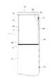
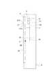
図13は、この発明の実施の形態3によるエレベータの制御盤1を示す正面図である。また、図14は、図13のエレベータの制御盤1を示す一部破断側面図である。さらに、図15は、図14の回動パネル6が閉塞位置から開放位置へ変位されるまでの途中の状態を示す一部破断側面図である。さらにまた、図16は、図14の回動パネル6が開放位置にある状態を示す一部破断側面図である。Embodiment 3 FIG.
FIG. 13 is a front view showing an
図において、保守対象機器7は、回動軸5から所定の距離だけ離して回動パネル6に取り付けられている。筐体4内には、保守対象機器7と異なる保守非対象機器31が収容されている。保守非対象機器31は、筐体4に取り付けられている。また、保守非対象機器31は、アクセス不可領域に配置されている。さらに、保守非対象機器31の一部は、通常位置にあるときの保守対象機器7と回動軸5との間の高さに配置されている。従って、保守非対象機器31は、保守対象機器7の通常位置の高さよりも下方に配置されている。 In the figure, the
保守非対象機器31は、保守点検の対象から除外されている機器である。即ち、保守非対象機器31は、エレベータの製品寿命よりも寿命の長い機器で、交換作業や配線の取り付け部分の増し締め作業を必要としない機器である。保守非対象機器31としては、例えばトランスやリアクトル、抵抗等が挙げられる。 The
他の構成は実施の形態1と同様である。また、保守対象機器7の保守点検作業を行うときの手順も実施の形態1と同様である。 Other configurations are the same as those in the first embodiment. Further, the procedure for performing the maintenance inspection work on the
このようなエレベータの制御盤1では、保守対象機器7が通常位置にあるときに保守対象機器7の下方に配置される保守非対象機器31が筐体4に設けられているので、保守点検の対象となっている保守対象機器7だけでなく、保守点検の対象から除外されている保守非対象機器31も、アクセス不可領域に配置することができ、アクセス不可領域をさらに有効に活用することができる。 In such an
なお、上記の例では、通常位置にあるときの保守対象機器7と回動軸5との間の高さに保守非対象機器31の一部が配置されているが、通常位置にあるときの保守対象機器7と回動軸5との間の高さに保守非対象機器31の全部が配置されていてもよい。 In the above example, a part of the
また、上記の例では、保守対象機器7の通常位置の高さよりも下方に保守非対象機器31が配置されているが、保守対象機器7の通常位置の高さよりも上方に保守非対象機器31を配置してもよい。 Further, in the above example, the
また、上記の例では、保守対象機器7を通常位置に保持する手段として、実施の形態1の操作レバー8及びフック12が用いられているが、実施の形態2の操作レバー8及びフック21を、保守対象機器7を通常位置に保持する手段として用いてもよい。 In the above example, the
また、各上記実施の形態では、操作レバー8が係合位置に変位されて操作レバー8とフック12,21とが係合されることにより、保守対象機器7が通常位置に保持されるようになっているが、保守対象機器7を通常位置に保持させることができるのであれば、フック12,21はなくてもよい。例えば、保守対象機器7が通常位置へ変位される方向へ回動パネル6を付勢する付勢体(例えば、捻りばね等)を回動軸5に設けることにより、保守対象機器7を通常位置に保持させるようにしてもよい。この場合、操作レバー8は回動パネル6に対して係合位置と解除位置との間で変位される必要はなく、操作レバー8がピン10を中心に回動可能になっていればよい。保守対象機器7が通常位置から点検位置へ変位されるときには、付勢体の付勢力に逆らって回動パネル6が閉塞位置から開放位置へ変位される。 Further, in each of the above embodiments, the
また、保守対象機器7が通常位置へ変位される方向へ回動パネル6を付勢する付勢体を回動軸5に設けた場合、回動パネル6から下方へ延びる操作部材を、操作レバー8ではなく、例えばロープ、ベルト又はチェーン等、曲げ可能な連続体としてもよい。 In addition, when the urging body that urges the
また、各上記実施の形態では、回動軸5が設けられた支持体が筐体4とされているが、これに限定されず、例えば支持体を矩形状の枠としてもよい。 Moreover, in each said embodiment, although the support body in which the
また、各上記実施の形態では、回動軸5が作業限界レベルAよりも上方に配置されているが、作業限界レベルAと同じ高さ又は作業限界レベルAよりも下方に回動軸5を配置してもよい。 In each of the above embodiments, the
また、各上記実施の形態では、回動パネル6の各側板6cのうち、一方のみにピン10を介して操作レバー8が取り付けられているが、各側板6cの両方にピン10を介して操作レバー8を取り付けてもよい。この場合、各操作レバー8は、回動パネル6に対して別個独立に変位されるようにしてもよいし、各操作レバー8を連結する連結部材を各操作レバー8の上端部間に固定することにより回動パネル6に対して一体となって変位されるようにしてもよい。 Moreover, in each said embodiment, although the
4 筐体(支持体)、5 回動軸、6 回動パネル(回動部材)、6a 機器取付板(機器取付部)、7 保守対象機器、8 操作レバー(操作部材)、9 開口部、12 フック、31 保守非対象機器。 4 Housing (support), 5 Rotating shaft, 6 Rotating panel (Rotating member), 6a Device mounting plate (Device mounting portion), 7 Maintenance target device, 8 Operation lever (Operation member), 9 Opening portion, 12 hook, 31 non-maintenance equipment.
Claims (5)
Translated fromJapanese上記支持体に設けられた回動軸を中心に回動可能な回動部材、
上記回動部材に設けられ、上記回動部材の回動により、上記回動軸よりも上方に位置する通常位置と、上記回動軸よりも下方に位置する点検位置との間で上記支持体に対して変位される保守対象機器、及び
上記回動部材から下方へ延び、外部からの引き下げ力を受けることにより、上記保守対象機器が上記通常位置から上記点検位置へ変位する方向へ上記回動部材を回動させる操作部材
を備え、
上記保守対象機器は、通常運転時に、上記通常位置に達することにより作業者の届かないアクセス不可領域に配置され、保守点検時にのみ、上記点検位置に達することにより作業者による保守点検が可能なアクセス可能領域へ変位されることを特徴とするエレベータの制御盤。A support arranged in the hoistway,
A rotating member rotatable about a rotation axis provided on the support,
The support member is provided between the normal position positioned above the rotation shaft and the inspection position positioned below the rotation shaft by the rotation of the rotation member. The maintenance target device that is displaced relative to the rotation member, and the rotation in the direction in which the maintenance target device is displaced from the normal position to the inspection position by receiving downward pulling force from the rotation member. An operation member for rotating the member,
The maintenance target device is placed in an inaccessible area that cannot be reached by the worker when it reaches the normal position during normal operation, and access that allows the worker to perform maintenance inspection by reaching the inspection position only during maintenance inspection. An elevator control panel that isdisplaced to a possible area .
上記操作部材は、上記保守対象機器が上記通常位置にあるときに、上記フックに係合する係合位置と、上記フックとの係合が外れる解除位置との間で上記回動部材に対して変位可能になっており、
上記保守対象機器は、上記操作部材が上記フックに係合されることにより、上記通常位置に保持されることを特徴とする請求項1に記載のエレベータの制御盤。The support is provided with a hook for holding the maintenance target device in the normal position,
When the maintenance target device is in the normal position, the operation member is located between the engagement position for engaging with the hook and the release position for releasing the engagement with the hook. Displaceable,
2. The elevator control panel according to claim 1, wherein the maintenance target device is held at the normal position when the operation member is engaged with the hook. 3.
上記支持体には、上記保守対象機器が上記通常位置にあるときに上記保守対象機器の下方に配置される保守非対象機器が設けられていることを特徴とする請求項1乃至請求項3のいずれか一項に記載のエレベータの制御盤。The maintenance target device is attached to the rotating member apart from the rotating shaft,
4. The maintenance object according to claim 1, wherein the support is provided with a maintenance non-target device disposed below the maintenance target device when the maintenance target device is in the normal position. The control panel of the elevator as described in any one.
上記回動軸は、上記開口部の縁部に設けられており、
上記回動部材は、上記保守対象機器が取り付けられる機器取付部を有し、
上記機器取付部は、上記保守対象機器が上記通常位置にあるときに上記回動軸よりも上記筐体の内側に配置されることを特徴とする請求項1乃至請求項4のいずれか一項に記載のエレベータの制御盤。The support is a housing provided with an opening,
The pivot shaft is provided at an edge of the opening,
The rotating member has a device mounting portion to which the maintenance target device is mounted,
5. The device mounting portion according to claim 1, wherein the device mounting portion is disposed inside the housing with respect to the rotation shaft when the device to be maintained is in the normal position. The elevator control panel described in 1.
Applications Claiming Priority (1)
| Application Number | Priority Date | Filing Date | Title |
|---|---|---|---|
| PCT/JP2010/068487WO2012053074A1 (en) | 2010-10-20 | 2010-10-20 | Elevator control panel |
Publications (2)
| Publication Number | Publication Date |
|---|---|
| JPWO2012053074A1 JPWO2012053074A1 (en) | 2014-02-24 |
| JP5523576B2true JP5523576B2 (en) | 2014-06-18 |
Family
ID=45974810
Family Applications (1)
| Application Number | Title | Priority Date | Filing Date |
|---|---|---|---|
| JP2012539512AActiveJP5523576B2 (en) | 2010-10-20 | 2010-10-20 | Elevator control panel |
Country Status (4)
| Country | Link |
|---|---|
| JP (1) | JP5523576B2 (en) |
| KR (1) | KR101420990B1 (en) |
| CN (1) | CN103167998B (en) |
| WO (1) | WO2012053074A1 (en) |
Families Citing this family (28)
| Publication number | Priority date | Publication date | Assignee | Title |
|---|---|---|---|---|
| US8590896B2 (en) | 2000-04-12 | 2013-11-26 | Shuffle Master Gmbh & Co Kg | Card-handling devices and systems |
| US8011661B2 (en) | 2001-09-28 | 2011-09-06 | Shuffle Master, Inc. | Shuffler with shuffling completion indicator |
| US7677565B2 (en) | 2001-09-28 | 2010-03-16 | Shuffle Master, Inc | Card shuffler with card rank and value reading capability |
| US8616552B2 (en) | 2001-09-28 | 2013-12-31 | Shfl Entertainment, Inc. | Methods and apparatuses for an automatic card handling device and communication networks including same |
| US7764836B2 (en) | 2005-06-13 | 2010-07-27 | Shuffle Master, Inc. | Card shuffler with card rank and value reading capability using CMOS sensor |
| US8579289B2 (en) | 2006-05-31 | 2013-11-12 | Shfl Entertainment, Inc. | Automatic system and methods for accurate card handling |
| US8353513B2 (en) | 2006-05-31 | 2013-01-15 | Shfl Entertainment, Inc. | Card weight for gravity feed input for playing card shuffler |
| US8342525B2 (en) | 2006-07-05 | 2013-01-01 | Shfl Entertainment, Inc. | Card shuffler with adjacent card infeed and card output compartments |
| US8070574B2 (en) | 2007-06-06 | 2011-12-06 | Shuffle Master, Inc. | Apparatus, system, method, and computer-readable medium for casino card handling with multiple hand recall feature |
| US8919775B2 (en) | 2006-11-10 | 2014-12-30 | Bally Gaming, Inc. | System for billing usage of an automatic card handling device |
| US8800993B2 (en) | 2010-10-14 | 2014-08-12 | Shuffle Master Gmbh & Co Kg | Card handling systems, devices for use in card handling systems and related methods |
| US8485527B2 (en) | 2011-07-29 | 2013-07-16 | Savant Shuffler LLC | Card shuffler |
| US8960674B2 (en)* | 2012-07-27 | 2015-02-24 | Bally Gaming, Inc. | Batch card shuffling apparatuses including multi-card storage compartments, and related methods |
| US9566501B2 (en) | 2014-08-01 | 2017-02-14 | Bally Gaming, Inc. | Hand-forming card shuffling apparatuses including multi-card storage compartments, and related methods |
| US9504905B2 (en) | 2014-09-19 | 2016-11-29 | Bally Gaming, Inc. | Card shuffling device and calibration method |
| BR112017013000A2 (en)* | 2014-12-17 | 2018-02-27 | Mitsubishi Electric Corp | ?elevator? |
| US9993719B2 (en) | 2015-12-04 | 2018-06-12 | Shuffle Master Gmbh & Co Kg | Card handling devices and related assemblies and components |
| US10339765B2 (en) | 2016-09-26 | 2019-07-02 | Shuffle Master Gmbh & Co Kg | Devices, systems, and related methods for real-time monitoring and display of related data for casino gaming devices |
| US10933300B2 (en) | 2016-09-26 | 2021-03-02 | Shuffle Master Gmbh & Co Kg | Card handling devices and related assemblies and components |
| EP3564174B1 (en) | 2018-05-03 | 2021-06-30 | Otis Elevator Company | Openable elevator car wall panels |
| US11896891B2 (en) | 2018-09-14 | 2024-02-13 | Sg Gaming, Inc. | Card-handling devices and related methods, assemblies, and components |
| US11376489B2 (en) | 2018-09-14 | 2022-07-05 | Sg Gaming, Inc. | Card-handling devices and related methods, assemblies, and components |
| WO2020055886A1 (en) | 2018-09-14 | 2020-03-19 | Sg Gaming, Inc. | Card-handling devices and related methods, assemblies, and components |
| US11338194B2 (en) | 2018-09-28 | 2022-05-24 | Sg Gaming, Inc. | Automatic card shufflers and related methods of automatic jam recovery |
| PH12020050309A1 (en) | 2019-09-10 | 2021-03-22 | Shuffle Master Gmbh And Co Kg | Card-handling devices with defect detection and related methods |
| US11173383B2 (en) | 2019-10-07 | 2021-11-16 | Sg Gaming, Inc. | Card-handling devices and related methods, assemblies, and components |
| KR102312838B1 (en) | 2020-11-03 | 2021-10-15 | 김석현 | Untact elevator system |
| JP7718558B1 (en)* | 2024-09-25 | 2025-08-05 | フジテック株式会社 | chassis |
Family Cites Families (9)
| Publication number | Priority date | Publication date | Assignee | Title |
|---|---|---|---|---|
| JP2526150Y2 (en)* | 1990-02-02 | 1997-02-19 | 日本電気株式会社 | Cover opening and closing link mechanism |
| CN2211993Y (en)* | 1994-06-21 | 1995-11-08 | 尹文三 | Complex control board for small winch |
| JP2001261247A (en) | 2000-03-24 | 2001-09-26 | Mitsubishi Electric Corp | Elevator control device |
| JP4792798B2 (en)* | 2005-04-13 | 2011-10-12 | 三菱電機株式会社 | Elevator control panel |
| CN2880778Y (en)* | 2006-01-26 | 2007-03-21 | 川方企业股份有限公司 | Power winch with portable and detachable handle and control box |
| WO2008105060A1 (en)* | 2007-02-27 | 2008-09-04 | Mitsubishi Electric Corporation | Elevator control panel |
| KR100918134B1 (en)* | 2008-05-07 | 2009-09-17 | 미쓰비시덴키 가부시키가이샤 | Elevator car rescue device |
| CN201372172Y (en)* | 2008-11-15 | 2009-12-30 | 王来朋 | Frequency-change variable-speed winch |
| JP2010180019A (en) | 2009-02-05 | 2010-08-19 | Mitsubishi Electric Corp | Operation equipment for elevator |
- 2010
- 2010-10-20JPJP2012539512Apatent/JP5523576B2/enactiveActive
- 2010-10-20CNCN201080069688.9Apatent/CN103167998B/enactiveActive
- 2010-10-20WOPCT/JP2010/068487patent/WO2012053074A1/enactiveApplication Filing
- 2010-10-20KRKR1020137012699Apatent/KR101420990B1/ennot_activeExpired - Fee Related
Also Published As
| Publication number | Publication date |
|---|---|
| JPWO2012053074A1 (en) | 2014-02-24 |
| KR20130114160A (en) | 2013-10-16 |
| CN103167998A (en) | 2013-06-19 |
| WO2012053074A1 (en) | 2012-04-26 |
| KR101420990B1 (en) | 2014-07-17 |
| CN103167998B (en) | 2015-06-10 |
Similar Documents
| Publication | Publication Date | Title |
|---|---|---|
| JP5523576B2 (en) | Elevator control panel | |
| JP5944008B2 (en) | Elevator control panel and elevator apparatus using the same | |
| JP6238270B2 (en) | Elevator equipment | |
| JP5572131B2 (en) | Elevator equipment | |
| JPWO2012127684A1 (en) | Rack and cable management equipment | |
| CN102736053A (en) | Lifting device for electric energy meter calibration device | |
| JP6336224B1 (en) | Elevator equipment | |
| JP2011190076A (en) | Safety belt hook device for elevator | |
| JP5524873B2 (en) | Elevator cable erection device and elevator cable erection method | |
| JP2016098106A (en) | Car fixation device for elevator | |
| JP6210937B2 (en) | Elevator equipment | |
| JP2013227837A (en) | Elevating scaffold device | |
| JP2009161346A (en) | Elevator | |
| JP5972161B2 (en) | Elevator equipment | |
| KR102364232B1 (en) | Movable Car Mounted Speed Controller | |
| JP4249006B2 (en) | Mobile work floor for elevator guide rail mounting | |
| JPWO2004074156A1 (en) | Elevator equipment | |
| WO2003104130A1 (en) | Elevator | |
| JP2007182281A (en) | Control panel inspection table device for elevator without machine room | |
| JP7749468B2 (en) | Electrical equipment and electrical equipment installation methods | |
| JP2012171756A (en) | Elevator apparatus | |
| JP2010247917A (en) | Lifting equipment for elevator equipment | |
| JP6917856B2 (en) | Lighting device | |
| KR20100052696A (en) | Apparatus for preventing crash of mobile robot | |
| JP5534797B2 (en) | Parts installation structure in hoistway |
Legal Events
| Date | Code | Title | Description |
|---|---|---|---|
| A521 | Request for written amendment filed | Free format text:JAPANESE INTERMEDIATE CODE: A523 Effective date:20140110 | |
| TRDD | Decision of grant or rejection written | ||
| A01 | Written decision to grant a patent or to grant a registration (utility model) | Free format text:JAPANESE INTERMEDIATE CODE: A01 Effective date:20140311 | |
| A61 | First payment of annual fees (during grant procedure) | Free format text:JAPANESE INTERMEDIATE CODE: A61 Effective date:20140408 | |
| R150 | Certificate of patent or registration of utility model | Ref document number:5523576 Country of ref document:JP Free format text:JAPANESE INTERMEDIATE CODE: R150 | |
| R250 | Receipt of annual fees | Free format text:JAPANESE INTERMEDIATE CODE: R250 | |
| R250 | Receipt of annual fees | Free format text:JAPANESE INTERMEDIATE CODE: R250 | |
| R250 | Receipt of annual fees | Free format text:JAPANESE INTERMEDIATE CODE: R250 | |
| R250 | Receipt of annual fees | Free format text:JAPANESE INTERMEDIATE CODE: R250 | |
| R250 | Receipt of annual fees | Free format text:JAPANESE INTERMEDIATE CODE: R250 | |
| R250 | Receipt of annual fees | Free format text:JAPANESE INTERMEDIATE CODE: R250 | |
| R250 | Receipt of annual fees | Free format text:JAPANESE INTERMEDIATE CODE: R250 | |
| R250 | Receipt of annual fees | Free format text:JAPANESE INTERMEDIATE CODE: R250 | |
| R250 | Receipt of annual fees | Free format text:JAPANESE INTERMEDIATE CODE: R250 |