JP5521954B2 - Electric power steering device - Google Patents
Electric power steering deviceDownload PDFInfo
- Publication number
- JP5521954B2 JP5521954B2JP2010219392AJP2010219392AJP5521954B2JP 5521954 B2JP5521954 B2JP 5521954B2JP 2010219392 AJP2010219392 AJP 2010219392AJP 2010219392 AJP2010219392 AJP 2010219392AJP 5521954 B2JP5521954 B2JP 5521954B2
- Authority
- JP
- Japan
- Prior art keywords
- motor
- steering
- control signal
- assist
- control
- Prior art date
- Legal status (The legal status is an assumption and is not a legal conclusion. Google has not performed a legal analysis and makes no representation as to the accuracy of the status listed.)
- Expired - Fee Related
Links
Images


Classifications
- B—PERFORMING OPERATIONS; TRANSPORTING
- B62—LAND VEHICLES FOR TRAVELLING OTHERWISE THAN ON RAILS
- B62D—MOTOR VEHICLES; TRAILERS
- B62D5/00—Power-assisted or power-driven steering
- B62D5/04—Power-assisted or power-driven steering electrical, e.g. using an electric servo-motor connected to, or forming part of, the steering gear
- B62D5/0457—Power-assisted or power-driven steering electrical, e.g. using an electric servo-motor connected to, or forming part of, the steering gear characterised by control features of the drive means as such
- B62D5/046—Controlling the motor
- B62D5/0472—Controlling the motor for damping vibrations
- B—PERFORMING OPERATIONS; TRANSPORTING
- B62—LAND VEHICLES FOR TRAVELLING OTHERWISE THAN ON RAILS
- B62D—MOTOR VEHICLES; TRAILERS
- B62D5/00—Power-assisted or power-driven steering
- B62D5/04—Power-assisted or power-driven steering electrical, e.g. using an electric servo-motor connected to, or forming part of, the steering gear
- B62D5/0403—Power-assisted or power-driven steering electrical, e.g. using an electric servo-motor connected to, or forming part of, the steering gear characterised by constructional features, e.g. common housing for motor and gear box
- H—ELECTRICITY
- H02—GENERATION; CONVERSION OR DISTRIBUTION OF ELECTRIC POWER
- H02P—CONTROL OR REGULATION OF ELECTRIC MOTORS, ELECTRIC GENERATORS OR DYNAMO-ELECTRIC CONVERTERS; CONTROLLING TRANSFORMERS, REACTORS OR CHOKE COILS
- H02P21/00—Arrangements or methods for the control of electric machines by vector control, e.g. by control of field orientation
- H02P21/0003—Control strategies in general, e.g. linear type, e.g. P, PI, PID, using robust control
- H—ELECTRICITY
- H02—GENERATION; CONVERSION OR DISTRIBUTION OF ELECTRIC POWER
- H02P—CONTROL OR REGULATION OF ELECTRIC MOTORS, ELECTRIC GENERATORS OR DYNAMO-ELECTRIC CONVERTERS; CONTROLLING TRANSFORMERS, REACTORS OR CHOKE COILS
- H02P29/00—Arrangements for regulating or controlling electric motors, appropriate for both AC and DC motors
- H02P29/02—Providing protection against overload without automatic interruption of supply
- H02P29/024—Detecting a fault condition, e.g. short circuit, locked rotor, open circuit or loss of load
- H02P29/025—Detecting a fault condition, e.g. short circuit, locked rotor, open circuit or loss of load the fault being a power interruption
Landscapes
- Engineering & Computer Science (AREA)
- Chemical & Material Sciences (AREA)
- Combustion & Propulsion (AREA)
- Transportation (AREA)
- Mechanical Engineering (AREA)
- Steering Control In Accordance With Driving Conditions (AREA)
- Power Steering Mechanism (AREA)
- Control Of Ac Motors In General (AREA)
Description
Translated fromJapanese本発明は、電動パワーステアリング装置に関するものである。 The present invention relates to an electric power steering apparatus.
従来、モータを駆動源としてステアリングシャフトを回転駆動することにより操舵系にアシスト力を付与する電動パワーステアリング装置(EPS)がある。この種のEPSは、1台のモータを制御することにより、走行状態に応じてアシスト特性を変更し、操舵フィーリングの向上を図っている。しかしながら、1台のモータによる制御では、平坦なアスファルト路(平坦路)からベルジャン路などの悪路に至るまで、きめ細かく対応できるアシスト特性設定には限界がある。
このため、アシスト特性設定の自由度を更に向上させるため、ステアリングから転舵輪に至るステアリング系に2つの駆動源を設けたEPSがある(例えば、特許文献1参照)。2. Description of the Related Art Conventionally, there is an electric power steering device (EPS) that applies assist force to a steering system by rotationally driving a steering shaft using a motor as a drive source. This type of EPS controls one motor to change the assist characteristic according to the running state, thereby improving the steering feeling. However, there is a limit to the setting of assist characteristics that can be dealt with finely, from flat asphalt roads (flat roads) to bad roads such as Belgian roads.
For this reason, there is an EPS in which two drive sources are provided in a steering system from a steering wheel to a steered wheel in order to further improve the degree of freedom of assist characteristic setting (see, for example, Patent Document 1).
しかしながら、上記の特許文献1のEPSにおいて、コラムEPSとピニオンEPSとの間は中間シャフト、ジョイントにより連結された構造のため、悪路を走行した場合、路面から転舵輪に逆入力が加わり、コラムEPSとピニオンEPSとの間に捩れが生じ、この捩れによる振動や回転がコラムEPSを介してステアリングに伝達される。
なお、転舵輪からの逆入力は、ピニオンEPSの機械的なフリクションやモータの慣性力による抗力が働き抑制されるが、中間シャフト、ジョイントによりコラムEPSに連結されているため、特に大きな逆入力の場合には、ステアリングへの伝達は避けられない。その結果、ハンドル取られや振動が発生し、車両の直進安定性が失われてしまう。
このように、転舵輪からの逆入力による操舵フィーリングの低下抑制が課題として残っており、なお改善の余地を残すものとなっていた。However, in the EPS of Patent Document 1 described above, the column EPS and the pinion EPS are connected by an intermediate shaft and a joint. Therefore, when driving on a rough road, a reverse input is applied to the steered wheels from the road surface. Torsion occurs between the EPS and the pinion EPS, and vibration and rotation due to the twist are transmitted to the steering via the column EPS.
Note that the reverse input from the steered wheels is restrained by the drag caused by the mechanical friction of the pinion EPS and the inertial force of the motor. However, since it is connected to the column EPS by the intermediate shaft and joint, it has a particularly large reverse input. In some cases, transmission to the steering is inevitable. As a result, the steering wheel is pulled and vibration is generated, and the straight running stability of the vehicle is lost.
As described above, the reduction of the steering feeling due to the reverse input from the steered wheels remains as a problem, and there is still room for improvement.
本発明は、上記問題点を解決するためになされたものであって、その目的は、平坦路と悪路の走行時の車両の直進安定性及び操舵フィーリングの向上を図ることができる電動パワーステアリング装置を提供することにある。 The present invention has been made in order to solve the above-described problems, and an object of the present invention is to provide an electric power capable of improving the straight running stability and steering feeling of a vehicle when traveling on a flat road and a rough road. The object is to provide a steering device.
上記問題点を解決するために、請求項1に記載の電動パワーステアリング装置は、独立に設けられた二系統のモータコイルが発生する起磁力に基づいて操舵系にアシスト力を付与する操舵力補助装置と、各モータコイルに対する電力供給を通じて前記操舵力補助装置の作動を制御する制御手段とを備えるとともに、前記制御手段は、前記アシスト力に対応したモータトルクを発生させるべく前記電力供給の電流指令値を生成する指令手段と、前記電流指令値に基づいて独立した二系統の制御信号を出力する制御信号出力手段と、前記制御信号に基づいて対応する前記モータコイルに三相の駆動電力を出力する独立した二系統の駆動回路とを備え、前記制御信号出力手段は、悪路走行時には前記モータコイルの三相のうち少なくとも二相間を短絡させることにより前記駆動回路に対して前記制御信号を出力すること、を要旨とする。 In order to solve the above problems, an electric power steering apparatus according to claim 1 is a steering force assisting device that applies assist force to a steering system based on magnetomotive force generated by two independently provided motor coils. And a control means for controlling the operation of the steering force assisting device through power supply to each motor coil, and the control means is a current command for supplying power to generate a motor torque corresponding to the assist force. Command means for generating a value, control signal output means for outputting two independent control signals based on the current command value, and outputting three-phase drive power to the corresponding motor coil based on the control signal Two independent drive circuits, and the control signal output means shortens at least two phases of the three phases of the motor coil when traveling on a rough road. Outputting the control signal to the drive circuit by, and the gist.
上記構成によれば、車両が悪路を走行していると判断した場合には、一方の系統のモータの三相のうち少なくとも二相間を短絡して制動動作(ダイナミック制動)させるようにする。その結果、悪路走行により入力される外乱エネルギーをモータの内部抵抗で発熱消費できるため、ステアリングのふらつき(ハンドル取られ)及び振動を抑制し直進安定性を維持できるとともに、操舵フィーリングの向上を図ることができる。 According to the above configuration, when it is determined that the vehicle is traveling on a rough road, a braking operation (dynamic braking) is performed by short-circuiting at least two phases of the three phases of the motor of one system. As a result, disturbance energy input by driving on rough roads can be generated and consumed by the internal resistance of the motor, so that steering stability and straight-line stability can be maintained by suppressing steering wobbling (steering of the steering wheel) and improving steering feeling. Can be planned.
請求項2に記載の電動パワーステアリング装置は、前記制御信号出力手段は、前記悪路走行時にはアシスト動作を実行していない系統の前記モータコイルの三相のうち少なくとも二相間を短絡させることにより前記駆動回路に対して前記制御信号を出力すること、を要旨とする。 The electric power steering device according to claim 2, wherein the control signal output means short-circuits at least two phases of the three phases of the motor coil of the system that is not performing the assist operation when traveling on the rough road. The gist is to output the control signal to the drive circuit.
上記構成によれば、車両が悪路を走行していると判断した場合には、一方の系統は操舵トルク及び車速に応じてアシストトルクを制御する従来のトルク制御を実行し、アシスト動作を行わない他方の系統のモータの少なくとも二相間を短絡して制動動作させるようにする。その結果、車両の直進安定性及び操舵フィーリングの向上を図ることができる。 According to the above configuration, when it is determined that the vehicle is traveling on a rough road, one system performs the conventional torque control for controlling the assist torque according to the steering torque and the vehicle speed, and performs the assist operation. A braking operation is performed by short-circuiting at least two phases of the motor of the other system not present. As a result, it is possible to improve the straight running stability and steering feeling of the vehicle.
本発明によれば、平坦路と悪路の走行時の車両の直進安定性及び操舵フィーリングの向上を図ることが可能な電動パワ−ステアリング装置を提供することができる。 ADVANTAGE OF THE INVENTION According to this invention, the electric power steering apparatus which can aim at the improvement of the straight running stability and steering feeling of the vehicle at the time of driving | running | working on a flat road and a rough road can be provided.
以下、本発明を具体化した実施形態を図面に従って説明する。
図1に示すように、本実施形態の電動パワーステアリング装置(EPS)1において、ステアリング2が固定されたステアリングシャフト3は、ラックアンドピニオン機構4を介してラック軸5と連結されている。そして、ステアリング操作に伴うステアリングシャフト3の回転は、ラックアンドピニオン機構4によりラック軸5の往復直線運動に変換される。なお、本実施形態のステアリングシャフト3は、コラムシャフト3a、インターミディエイトシャフト3b、及びピニオンシャフト3cを連結している。そして、このステアリングシャフト3の回転に伴うラック軸5の往復直線運動が、同ラック軸5の両端に連結されたタイロッド6を介して図示しないナックルに伝達されることにより、転舵輪7の舵角、即ち車両の進行方向が変更される。DESCRIPTION OF EXEMPLARY EMBODIMENTS Hereinafter, embodiments of the invention will be described with reference to the drawings.
As shown in FIG. 1, in the electric power steering apparatus (EPS) 1 of this embodiment, a
また、EPS1は、操舵系にステアリング操作を補助するためのアシスト力を付与する操舵力補助装置としてのEPSアクチュエータ10と、該EPSアクチュエータ10の作動を制御する制御手段としてのECU11とを備えている。 Further, the EPS 1 includes an
本実施形態のEPSアクチュエータ10は、駆動源であるモータ12が減速機構13を介してコラムシャフト3aと駆動連結された所謂コラムアシストタイプのEPSアクチュエータとして構成されている。そして、EPSアクチュエータ10は、このモータ12の回転を減速してコラムシャフト3aに伝達することにより、そのモータトルクをアシスト力として操舵系に付与する構成となっている。 The
一方、ECU11には、トルクセンサ14及び車速センサ15が接続されており、同ECU11は、これら各センサの出力信号により検出される操舵トルクτ及び車速Vに基づいて操舵系に付与すべきアシスト力(目標アシスト力)を演算する。そして、その目標アシスト力をEPSアクチュエータ10に発生させるべく、駆動源であるモータ12に対する電力供給を通じて、当該EPSアクチュエータ10の作動、即ち操舵系に付与するアシスト力を制御する(パワーアシスト制御)。 On the other hand, a
次に、本実施形態のEPSの電気的構成について説明する。
図2に示すように、本実施形態のモータ12は、独立した二系統のモータコイル21A,21Bを同一のステータ22に巻回することにより形成されている。具体的には、第1系統のモータコイル21A(21ua,21va,21wa)及び第2系統のモータコイル21B(21ub,21vb,21wb)は、ステータ22の各ティース23(23u,23v,23w)に対して、それぞれその対応する相(u,v,w)毎に巻回されている。そして、これらの各ティース23の径方向内側には、回転自在に支承されたロータ24が設けられている。Next, the electrical configuration of the EPS of this embodiment will be described.
As shown in FIG. 2, the
即ち、本実施形態のモータ12は、二系統のモータコイル21A,21Bに共通のステータ22及びロータ24を有しており、ロータ24は、上記のように各ティース23に巻回された各モータコイル21A,21Bが発生する起磁力に基づいて回転する。そして、本実施形態のECU11は、これらの各モータコイル21A,21Bに対して、それぞれ独立に駆動電力を供給することにより、そのモータトルクを制御する構成になっている。 That is, the
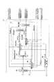
図3に示すように、本実施形態のECU11は、上記各モータコイル21A,21Bに対応して独立に設けられた二つの駆動回路26A,26Bと、これらの各駆動回路26A,26Bに対して、それぞれ独立に制御信号Smc_a,Smc_bを出力するマイコン27とを備えている。 As shown in FIG. 3, the
具体的には,駆動回路26Aは、動力線28A(28ua,28va,28wa)を介して第1系統のモータコイル21Aに接続され、駆動回路26Bは、動力線28B(28ub,28vb,28wb)を介して第2系統のモータコイル21Bに接続されている。また、マイコン27の出力する制御信号Smc_aは、駆動回路26Aに入力され、もう一方の制御信号Smc_bは、駆動回路26Bに入力される。なお、本実施形態では、各駆動回路26A,26Bには、直列接続されたスイッチング素子対を基本単位(アーム)として各相に対応する3つのアームを並列接続してなる周知のPWMインバータが採用されており、マイコン27の出力する各制御信号Smc_a,Smc_bは、その各相アームのオンduty比を規定するものとなっている。そして、本実施形態のECU11は、これらの各制御信号Smc_a,Smc_bに基づき各駆動回路26A,26Bが出力する駆動電力を、それぞれ独立に、その対応する各モータコイル21A,21Bに供給する構成となっている。 Specifically, the
詳述すると、図4に示すように、本実施形態のマイコン27は、目標アシスト力に対応するモータトルクを発生させるべく、モータ12に対する電力供給の電流指令値Iq*を生成するアシスト制御部30と、その電流指令値Iq*に基づいて上記二系統の制御信号Smc_a,Smc_bの出力を実行する制御信号出力部31とを備えている。 More specifically, as shown in FIG. 4, the
本実施形態では、指令手段としてのアシスト制御部30は、上記トルクセンサ14により検出される操舵トルクτ及び車速センサ15により検出される車速Vに基づいて、上記目標アシスト力に対応した電流指令値Iq*を演算する。具体的には,その操舵トルクτが大きいほど、また車速Vが遅いほど、より大きなアシスト力が発生するような電流指令値Iq*を演算する。そして、アシスト制御部30は、この操舵トルクτ及び車速Vに基づく電流指令値Iq*を、そのモータ12に対する電力供給の電流指令値Iq*として制御信号出力部31に出力する構成となっている。 In the present embodiment, the
一方、制御信号出力手段を構成する制御信号出力部31には、各系統のモータコイル21A,21B(図2参照)に通電される各相電流値Iu_a,Iv_a,Iw_a及びIu_b,Iv_b,Iw_b並びにモータ12の回転角θが入力される。なお、本実施形態では、各相電流値Iu_a,Iv_a,Iw_a及びIu_b,Iv_b,Iw_bは、図3を参照にそれぞれ、各系統の動力線28A,28Bに設けられた電流センサ32A(32ua,32va,32wa),32B(32ub,32vb,32wb)により独立に検出される一方、モータ12の回転角θは、共通の回転角センサ33により検出される。そして、本実施形態の制御信号駆動回路26A,26Bに対応した制御信号Smc_a,Smc_bを出力する構成となっている。 On the other hand, in the control
更に詳述すると、本実施形態の制御信号出力部31は、第1系統(図3に示す駆動回路26A、モータコイル21A及び動力線28Aを含む系統)に対応する電流制御部35A及びPWM変換部36Aと、第2系統(図3に示す駆動回路26B、モータコイル21B及び動力線28Bを含む系統)に対応する電流制御部35B及びPWM変換部36Bとを備えている。 More specifically, the control
また、制御信号出力部31は、上記アシスト制御部30から入力された電流指令値Iq*を、第1電流指令値Iq*_a又は第2電流指令値Iq*_bとして出力する指令調停部37を備えている。そして、各電流制御部35(35A,35B)は、その入力される電流指令値Iq*_a,Iq*_bに基づいて、それぞれ、独立に電流フィードバック制御を実行する構成となっている。 The control
具体的には、各電流制御部35(35A,35B)は、その対応する系統の各相電流値Iu_a,Iv_a,Iw_a及びIu_b,Iv_b,Iw_bを、モータ12の回転角θに従うd/q座標系のd軸電流値及びq軸電流値に変換する(d/q変換)。また、上記電流指令値Iq*は、q軸電流指令値として入力される(d軸電流指令値は「0」)。そして、各電流指令部35(35A,35B)は、そのd/q座標系における電流フィードバック制御の実行により得られるd軸電圧指令値及びq軸電圧指令値を、三相の交流座標系上に写像することにより(d/q逆変換)、それぞれ、その対応する系統の各相電圧指令値Vu*_a,Vv*_a,Vw*_a及びVu*_b,Vv*_b,Vw*_bを演算する。 Specifically, each current control unit 35 (35A, 35B) uses each phase current value Iu_a, Iv_a, Iw_a and Iu_b, Iv_b, Iw_b of the corresponding system as d / q coordinates according to the rotation angle θ of the
そして、各PWM変換部36(36A,36B)は、それぞれ、その対応する各電流制御部35(35A,35B)から入力される各相電圧指令値Vu*_a,Vv*_a,Vw*_a及びVu*_b,Vv*_b,Vw*_bに基づいて、その対応する系統の駆動回路26A,26Bに対する制御信号Smc_a,Smc_bの出力を実行する構成になっている。 The PWM converters 36 (36A, 36B) respectively receive the phase voltage command values Vu * _a, Vv * _a, Vw * _a input from the corresponding current controllers 35 (35A, 35B). Based on Vu * _b, Vv * _b, and Vw * _b, the control signals Smc_a and Smc_b are output to the
また、図4に示すように、本実施形態のマイコン27には、上記車両が走行する路面状態を検知可能な走行路状態検出部39が設けられている。本実施形態の走行路状態検出部39は、例えば、車速センサ15及び加速度センサ(図示しない)から供給される車速V及び車両の上下加速度Gに基づいて車両が走行している路面状態を判断する。 As shown in FIG. 4, the
次に、本実施形態におけるEPSの制御について説明する。
図4に示すように、本実施形態のマイコン27には、上記各モータコイル21A,21B(図2参照)に対応する各系統の電力供給路に生じた通電不良の発生を検知可能な異常検知部38が設けられている。Next, EPS control in the present embodiment will be described.
As shown in FIG. 4, the
具体的には,本実施形態の異常検知部38には、各系統のモータコイル21A,21Bに通電される各相電流値Iu_a,Iv_a,Iw_a及びIu_b,Iv_b,Iw_b、並びに各制御信号Smc_a,Smc_bが規定する各相のオンdutyを示すデューティ信号Sduty_b,Sduty_b及びモータ12の回転角速度ωが入力される。そして、検知手段としての異常検知部38は、これらの各状態量に基づいて、相毎に、各系統における通電不良の発生を検知する構成となっている。 Specifically, the
即ち、何れかの相について、そのデューティ信号Sduty_b,Sduty_bが通電状態にあるべき状態にあることを示すにもかかわらず、その相電流値が非通電状態を示す値である場合には,当該相に通電不良が発生したものと判定することができる。そして、本実施形態の異常検知部38は、更に、モータの回転角速度ωに基づく速度条件を付加し、その逆起電圧の影響が顕在化する高速回転時を排除することにより、精度よく、その通電不良の発生を検知することが可能な構成となっている。 That is, when any of the phases indicates that the duty signals Sduty_b and Sduty_b are in a state where they should be energized, the phase current value is a value indicating a non-energized state. It can be determined that an energization failure has occurred. Then, the
また、本実施形態では、この異常検知部38による異常検知の結果が、異常検知信号として上記制御信号出力部31に入力されるようになっている。そして、本実施形態の制御信号出力部31は、上記各モータコイル21A,21Bに対応する二系統のうち、その一方の系統に通電不良の発生が検知された場合には、他方の系統の駆動回路に対する制御信号の出力を優先する構成となっている。 In the present embodiment, the result of abnormality detection by the
詳述すると、図5のフローチャートに示すように、本実施形態の制御信号出力部31において、指令調停部37は、入力される上記異常検知信号S_trが、通電不良の検知を示す場合(ステップ501:YES)には、続いて、当該通電不良が上記モータコイル21Aに対応する第1系統において発生したものであるか否かを判定する(ステップ502)。そして、その通電不良の発生が第1系統である場合(ステップ502:YES)には、第1系統における電力供給を停止し(ステップ503)、他方の上記モータコイル21Bに対応する第2系統の駆動回路26Bに対する制御信号Smc_bの出力を優先する(ステップ504)。 More specifically, as shown in the flowchart of FIG. 5, in the control
また、指令調停部37は、上記ステップ502において、通電不良の発生が第2系統であると判定した場合(ステップ502:NO)には、第2系統における電力供給を停止し(ステップ505)、第1系統の駆動回路26Aに対する制御信号Smc_aの出力を優先する(ステップ506)。そして、本実施形態では、上記ステップ501において、上記異常検知信号S_trが通電不良の発生を示すものでないと判定した場合(ステップ501:NO)もまた、ステップ510(後述する)において、その第1系統の駆動回路26Aに対する制御信号Smc_aの出力を優先する。 If the
本実施形態の制御信号出力部31に設けられた上記各電流制御部35(35A,35B)は、各系統における通電不良の発生が検知されていない正常時において、上記のような三相の駆動電力を供給すべく各相電圧指令値Vu*,Vv*,Vw*を演算する。上記電流制御部35において演算された各相電圧指令値Vu*,Vv*,Vw*は、上記異常検知信号S_trとともに、PWM変換部36に入力される。即ち、本実施形態の制御信号出力部31において、入力される異常検知信号S_trが「対応する系統における通電不良の発生は検知されていない」ことを示す場合には、車両が悪路走行中か否かを判断し、通常の良好な路面を走行中と判断された場合には、第2系統のモータコイルの三相を開放すべく、その対応するPWM変換部36Bにおいて上下アームが全オフとなる制御信号Smc_bを出力する。(通常制御) Each of the current control units 35 (35A, 35B) provided in the control
一方、車両が悪路走行中と判断された場合には、少なくともモータコイルの二相間が短絡状態となるように第2系統のPWM変換部36Bにおいて上又は下アームが全オンとなる制御信号Smc_bを出力する。 On the other hand, if it is determined that the vehicle is traveling on a rough road, the control signal Smc_b that turns on the upper or lower arm in the
詳述すると、図5のフローチャートに示すように、本実施形態の制御信号出力部31は、車速センサ15及び加速度センサ(図示しない)から入力される車速V及び車両の上下加速度Gから走行モード検知信号S_rdが、通常の良好な路面走行中を示す場合(ステップ507:NO)は、第2系統のモータコイルの三相を開放する(ステップ508)。続いて、第1系統でのアシスト制御を継続実行するため第1系統の駆動回路26Aに対する制御信号Smc_aを出力する(ステップ510)。そして、車両が悪路走行中の検知を示す場合(ステップ507:YES)には、第2系統を制動モード(例えば、インバータの上あるいは下アームを通して制動電流を流すダイナミック制動)で駆動する(ステップ509)。続いて、第1系統はアシスト制御を継続実行するため第1系統の駆動回路26Aに対する制御信号Smc_aを出力する。(ステップ510)。 More specifically, as shown in the flowchart of FIG. 5, the control
以上、本実施形態によれば、以下のような作用・効果を得ることができる。
本実施形態のモータは、二系統のモータコイルに共通のステータ及びロータを有しており、ロータは、上記のように各ティースに巻回された各モータコイルが発生する起磁力に基づいて回転する。そして、本実施形態のECU(制御手段)は、これらの各モータコイルに対して、それぞれ独立に駆動電力を供給することにより、そのモータトルクを制御する構成になっている。即ち、本実施形態のECUは、上記各モータコイルに対応して独立に設けられた二つの駆動回路と、これらの各駆動回路に対して、それぞれ独立に制御信号を出力するマイコンとを備えるようにした。As described above, according to the present embodiment, the following operations and effects can be obtained.
The motor of this embodiment has a stator and a rotor that are common to the two motor coils, and the rotor rotates based on the magnetomotive force generated by each motor coil wound around each tooth as described above. To do. And ECU (control means) of this embodiment is the structure which controls the motor torque by supplying drive electric power to each of these motor coils each independently. That is, the ECU of the present embodiment includes two drive circuits provided independently corresponding to the motor coils, and a microcomputer that outputs control signals to the drive circuits independently. I made it.
上記構成によれば、車両が通常の良好な路面走行時は、一方の系統は操舵トルク及び車速に応じてアシストトルクを制御する従来のトルク制御を実行し、他方の系統は、通常はモータを開放状態として動作させない。また、車両が悪路走行していると判断した場合には、他方の系統のモータの少なくとも二相間を短絡して制動動作(ダイナミック制動)させるようにする。その結果、悪路走行により入力される外乱エネルギーをモータの内部抵抗で発熱消費できるため、ステアリングのふらつき(ハンドル取られ)及び振動を抑制し直進安定性を維持できるとともに、操舵フィーリングの向上を図ることができる。 According to the above configuration, when the vehicle is running on a normal good road surface, one system executes the conventional torque control that controls the assist torque according to the steering torque and the vehicle speed, and the other system normally operates the motor. Do not operate in the open state. If it is determined that the vehicle is traveling on a rough road, the braking operation (dynamic braking) is performed by short-circuiting at least two phases of the motors of the other system. As a result, disturbance energy input by driving on rough roads can be generated and consumed by the internal resistance of the motor, so that steering stability and straight-line stability can be maintained by suppressing steering wobbling (steering of the steering wheel) and improving steering feeling. Can be planned.
また、モータを共通のステータ及びロータ構成にすることにより装置の大型化を招くことなく、モータの低コスト化を図ることができる。そして、アシスト制御を実行している系統のインバータに通電不良が発生した場合に、他方の正常な系統のインバータで従来のトルク制御を実行させアシスト動作を継続する。その結果、通電不良が発生した系統の電力供給を停止して、正常な系統でのアシスト制御に切替えることによって、トルクリップルの発生がなく操舵を継続できる。 Further, by using a common stator and rotor configuration for the motor, the cost of the motor can be reduced without increasing the size of the apparatus. When a power failure occurs in the inverter of the system that is executing the assist control, the conventional torque control is executed by the other normal system of inverter and the assist operation is continued. As a result, by stopping the power supply of the system in which the energization failure has occurred and switching to the assist control in the normal system, the steering can be continued without generating torque ripple.
なお、上記実施形態は以下のように変更してもよい。
・上記各実施形態では、本発明をコラムアシストタイプのEPS1に具体化したが、本発明は、ピニオンアシストタイプやラックアシストタイプのEPSに適用してもよい。
・上記各実施形態では、EPSアクチュエータ10は、二系統のモータコイル21A,21Bに対して共通のステータ22及びロータ24を有するモータ12を駆動源とすることとした。しかし、これに限らず、各モータコイルが個別のステータ又は個別のロータを有する構成に具体化してもよい。そして、更に、2台のモータを駆動源とするものに適用してもよい。
・また、各系統のモータコイルについては、その位相が互いにずれた関係となるように配置される構成であってもよい。
・上記実施形態では、車両が悪路走行中に第2系統のモータコイルの少なくとも二相を短絡させて制動モードで駆動するとしたが、間欠的に短絡、開放を繰り返し、制動、フリー状態で制御してもよい。また、モータの回転速度に応じて間欠から短絡へ変化させるPWM制御としてもよいし、モータ回転変動の周期に応じて変化させてもよい。
・上記実施形態では、車両が通常路面を走行中は、第2系統のモータコイルを開放しているが、第2系統のモータトルク出力が0となるように制御してもよい。In addition, you may change the said embodiment as follows.
In each of the above embodiments, the present invention is embodied in the column assist type EPS 1, but the present invention may be applied to a pinion assist type or rack assist type EPS.
In each of the above embodiments, the
-Moreover, about the motor coil of each system | strain, the structure arrange | positioned so that the phase may mutually become the relationship shifted | deviated may be sufficient.
In the above embodiment, when the vehicle is traveling on a rough road, at least two phases of the motor coil of the second system are short-circuited and driven in the braking mode. May be. Moreover, it is good also as PWM control changed from intermittent to a short circuit according to the rotational speed of a motor, and you may change according to the period of motor rotation fluctuation | variation.
In the above embodiment, the motor coil of the second system is opened while the vehicle is traveling on a normal road surface. However, the motor torque output of the second system may be controlled to be zero.
1:電動パワーステアリング装置(EPS)、2:ステアリング、
3:ステアリングシャフト、3a:コラムシャフト、3b:インターミディエイトシャフト、3c:ピニオンシャフト、4:ラックアンドピニオン機構、5:ラック軸、
6:タイロッド、7:転舵輪、10:EPSアクチュエータ、11:ECU、12:モータ、13:減速機構、14:トルクセンサ、15:車速センサ、
21A,21B:モータコイル、22:ステータ、24:ロータ、26A,26B:駆動回路、27:マイコン、28A,28B:動力線、30:アシスト制御部、31:制御信号出力部、32A,32B:電流センサ、Iu_a、Iv_a、Iw_a、Iu_b、Iv_b、Iw_b:各相電流値、33:モータ回転角センサ、35:電流制御部、36:PWM変換部、37:指令調停部、38:異常検知部、39:走行路状態検出部、
Iq*:q軸電流指令値、Iq*_a:第1電流指令値、Iq*_b:第2電流指令値、
Vu*_a,Vv*_a,Vw*_a,Vu*_b,Vv*_b,Vw*_b:各相電圧指令値、
Smc_a,Smc_b:制御信号、S_tr:異常検知信号、S_rd:走行モード検知信号、
Sduty_b,Sduty_b:デューティ信号
θ:モータ回転角、V:車速、τ:操舵トルク、G:車両の上下加速度1: Electric power steering device (EPS), 2: Steering,
3: Steering shaft, 3a: Column shaft, 3b: Intermediate shaft, 3c: Pinion shaft, 4: Rack and pinion mechanism, 5: Rack shaft,
6: Tie rod, 7: Steering wheel, 10: EPS actuator, 11: ECU, 12: Motor, 13: Deceleration mechanism, 14: Torque sensor, 15: Vehicle speed sensor,
21A, 21B: Motor coil, 22: Stator, 24: Rotor, 26A, 26B: Drive circuit, 27: Microcomputer, 28A, 28B: Power line, 30: Assist control unit, 31: Control signal output unit, 32A, 32B: Current sensor, Iu_a, Iv_a, Iw_a, Iu_b, Iv_b, Iw_b: Current value of each phase, 33: Motor rotation angle sensor, 35: Current control unit, 36: PWM conversion unit, 37: Command arbitration unit, 38: Abnormality detection unit 39: Traveling road state detection unit,
Iq *: q-axis current command value, Iq * _a: first current command value, Iq * _b: second current command value,
Vu * _a, Vv * _a, Vw * _a, Vu * _b, Vv * _b, Vw * _b: Voltage command values for each phase,
Smc_a, Smc_b: control signal, S_tr: abnormality detection signal, S_rd: travel mode detection signal,
Sduty_b, Sduty_b: Duty signal θ: Motor rotation angle, V: Vehicle speed, τ: Steering torque, G: Vertical acceleration of vehicle
Claims (2)
Translated fromJapanese前記制御手段は、前記アシスト力に対応したモータトルクを発生させるべく前記電力供給の電流指令値を生成する指令手段と、
前記基礎指令に基づいて独立した二系統の制御信号を出力する制御信号出力手段と、
前記制御信号に基づいて対応する前記モータコイルに三相の駆動電力を出力する独立した二系統の駆動回路と、を備え、
前記制御信号出力手段は、悪路走行時には前記モータコイルの三相のうち少なくとも二相間を短絡させることにより前記駆動回路に対して前記制御信号を出力すること、を特徴とする電動パワーステアリング装置。A steering force assist device that applies assist force to the steering system based on magnetomotive force generated by two independently provided motor coils, and a control that controls the operation of the steering force assist device through power supply to each motor coil Means, and
The control means generates a current command value of the power supply to generate a motor torque corresponding to the assist force;
Control signal output means for outputting two independent control signals based on the basic command;
Two independent drive circuits that output three-phase drive power to the corresponding motor coil based on the control signal, and
The electric power steering device according to claim 1, wherein the control signal output means outputs the control signal to the drive circuit by short-circuiting at least two phases of the three phases of the motor coil when traveling on a rough road.
前記制御信号出力手段は、前記悪路走行時にはアシスト動作を実行していない系統の前記モータコイルの三相のうち少なくとも二相間を短絡させることにより前記駆動回路に対して前記制御信号を出力すること、を特徴とする電動パワーステアリング装置。The electric power steering apparatus according to claim 1, wherein
The control signal output means outputs the control signal to the drive circuit by short-circuiting at least two phases of the three phases of the motor coil of the system not performing the assist operation during the rough road traveling. An electric power steering apparatus characterized by the above.
Priority Applications (5)
| Application Number | Priority Date | Filing Date | Title |
|---|---|---|---|
| JP2010219392AJP5521954B2 (en) | 2010-09-29 | 2010-09-29 | Electric power steering device |
| CN201180047443.0ACN103140406B (en) | 2010-09-29 | 2011-09-28 | Electric power steering apparatus |
| US13/876,597US8983730B2 (en) | 2010-09-29 | 2011-09-28 | Electric power steering apparatus |
| EP11781853.4AEP2621789B1 (en) | 2010-09-29 | 2011-09-28 | Electric power steering apparatus |
| PCT/IB2011/002261WO2012042351A1 (en) | 2010-09-29 | 2011-09-28 | Electric power steering apparatus |
Applications Claiming Priority (1)
| Application Number | Priority Date | Filing Date | Title |
|---|---|---|---|
| JP2010219392AJP5521954B2 (en) | 2010-09-29 | 2010-09-29 | Electric power steering device |
Publications (2)
| Publication Number | Publication Date |
|---|---|
| JP2012071759A JP2012071759A (en) | 2012-04-12 |
| JP5521954B2true JP5521954B2 (en) | 2014-06-18 |
Family
ID=44936309
Family Applications (1)
| Application Number | Title | Priority Date | Filing Date |
|---|---|---|---|
| JP2010219392AExpired - Fee RelatedJP5521954B2 (en) | 2010-09-29 | 2010-09-29 | Electric power steering device |
Country Status (5)
| Country | Link |
|---|---|
| US (1) | US8983730B2 (en) |
| EP (1) | EP2621789B1 (en) |
| JP (1) | JP5521954B2 (en) |
| CN (1) | CN103140406B (en) |
| WO (1) | WO2012042351A1 (en) |
Families Citing this family (7)
| Publication number | Priority date | Publication date | Assignee | Title |
|---|---|---|---|---|
| JP5981219B2 (en)* | 2012-05-18 | 2016-08-31 | 株式会社マキタ | Braking device for three-phase brushless motor and electrical equipment |
| DE102012012307A1 (en)* | 2012-06-20 | 2013-12-24 | Volkswagen Aktiengesellschaft | Method for suppressing disturbances in a steering system of a motor vehicle and steering system in a motor vehicle |
| JP6383353B2 (en) | 2013-03-18 | 2018-08-29 | 本田技研工業株式会社 | Vehicle steering system |
| CN105720865A (en)* | 2014-12-04 | 2016-06-29 | 德昌电机(深圳)有限公司 | DC brushless motor, control method therefor, and power-assisted steering system |
| US10574172B2 (en)* | 2016-03-04 | 2020-02-25 | Nidec Corporation | Power conversion device, motor drive unit, and electric power steering device |
| DE102022201437B3 (en) | 2022-02-11 | 2023-08-03 | Zf Friedrichshafen Ag | Control arrangement of a six-phase electrical machine |
| CN114919649A (en)* | 2022-06-16 | 2022-08-19 | 上汽通用五菱汽车股份有限公司 | Electric power steering control method, electric power steering control system, vehicle, and computer-readable storage medium |
Family Cites Families (14)
| Publication number | Priority date | Publication date | Assignee | Title |
|---|---|---|---|---|
| JP3187087B2 (en)* | 1991-09-19 | 2001-07-11 | 東芝キヤリア株式会社 | Control device for air conditioner |
| US5670854A (en)* | 1994-12-14 | 1997-09-23 | Matsushita Electric Industrial Co., Ltd. | Control system for an induction motor |
| US20030193308A1 (en)* | 2002-04-16 | 2003-10-16 | Richardson Gordon D. | Apparatus and method for testing a motor-shorting relay |
| JP3839358B2 (en)* | 2002-06-12 | 2006-11-01 | 株式会社ジェイテクト | Vehicle steering control device and vehicle steering control method |
| JP3875188B2 (en)* | 2002-12-16 | 2007-01-31 | 株式会社ジェイテクト | Electric motor device |
| JP2004201414A (en)* | 2002-12-18 | 2004-07-15 | Toyoda Mach Works Ltd | Apparatus and method for controlling motor and electric power steering apparatus |
| JP4355189B2 (en)* | 2003-10-10 | 2009-10-28 | 日本精工株式会社 | Control device for electric power steering device |
| JP2005247214A (en) | 2004-03-05 | 2005-09-15 | Nsk Ltd | Electric power steering device |
| JP2005329784A (en)* | 2004-05-19 | 2005-12-02 | Hitachi Ltd | Electric power steering device |
| JP2006273155A (en)* | 2005-03-29 | 2006-10-12 | Showa Corp | Electric power steering device |
| JP4749852B2 (en)* | 2005-11-30 | 2011-08-17 | 日立オートモティブシステムズ株式会社 | Motor drive device and automobile using the same |
| JP5037156B2 (en)* | 2006-09-26 | 2012-09-26 | 株式会社ジェイテクト | Electric power steering device |
| JP4404160B2 (en)* | 2008-01-21 | 2010-01-27 | ダイキン工業株式会社 | Motor drive control device |
| JP5168362B2 (en)* | 2009-01-22 | 2013-03-21 | トヨタ自動車株式会社 | Electric power steering device |
- 2010
- 2010-09-29JPJP2010219392Apatent/JP5521954B2/ennot_activeExpired - Fee Related
- 2011
- 2011-09-28WOPCT/IB2011/002261patent/WO2012042351A1/enactiveApplication Filing
- 2011-09-28USUS13/876,597patent/US8983730B2/ennot_activeExpired - Fee Related
- 2011-09-28CNCN201180047443.0Apatent/CN103140406B/ennot_activeExpired - Fee Related
- 2011-09-28EPEP11781853.4Apatent/EP2621789B1/ennot_activeNot-in-force
Also Published As
| Publication number | Publication date |
|---|---|
| US20130218417A1 (en) | 2013-08-22 |
| EP2621789A1 (en) | 2013-08-07 |
| EP2621789B1 (en) | 2014-07-09 |
| WO2012042351A1 (en) | 2012-04-05 |
| CN103140406B (en) | 2016-04-13 |
| CN103140406A (en) | 2013-06-05 |
| JP2012071759A (en) | 2012-04-12 |
| US8983730B2 (en) | 2015-03-17 |
Similar Documents
| Publication | Publication Date | Title |
|---|---|---|
| JP5633260B2 (en) | Electric power steering device | |
| JP5569273B2 (en) | Electric power steering device | |
| EP2625088B1 (en) | Electric power steering apparatus | |
| JP5521954B2 (en) | Electric power steering device | |
| JP5070867B2 (en) | Motor control device and electric power steering device | |
| JP5672936B2 (en) | Electric power steering device | |
| JP3674919B2 (en) | Electric power steering apparatus and control method thereof | |
| WO2009123107A1 (en) | Motor control device and electric power steering device | |
| JP2013159165A (en) | Electric power steering device | |
| JP5991264B2 (en) | Electric power steering device | |
| JP2013071550A (en) | Control unit for vehicle steering system | |
| JP5699527B2 (en) | Electric power steering device | |
| JP2006256542A (en) | Electric power steering device | |
| JP2012076644A (en) | Electric power steering device | |
| JP2013005624A (en) | Vehicle steering device | |
| JP5176369B2 (en) | Electric power steering device | |
| JP5131435B2 (en) | Electric power steering device | |
| JP2012072733A (en) | Electric power steering device | |
| JP2012224146A (en) | Electric power steering apparatus |
Legal Events
| Date | Code | Title | Description |
|---|---|---|---|
| A621 | Written request for application examination | Free format text:JAPANESE INTERMEDIATE CODE: A621 Effective date:20130821 | |
| A977 | Report on retrieval | Free format text:JAPANESE INTERMEDIATE CODE: A971007 Effective date:20140225 | |
| TRDD | Decision of grant or rejection written | ||
| A01 | Written decision to grant a patent or to grant a registration (utility model) | Free format text:JAPANESE INTERMEDIATE CODE: A01 Effective date:20140311 | |
| A61 | First payment of annual fees (during grant procedure) | Free format text:JAPANESE INTERMEDIATE CODE: A61 Effective date:20140324 | |
| R150 | Certificate of patent or registration of utility model | Ref document number:5521954 Country of ref document:JP Free format text:JAPANESE INTERMEDIATE CODE: R150 | |
| LAPS | Cancellation because of no payment of annual fees |