JP5521370B2 - Retransmission method and relay station - Google Patents
Retransmission method and relay stationDownload PDFInfo
- Publication number
- JP5521370B2 JP5521370B2JP2009072180AJP2009072180AJP5521370B2JP 5521370 B2JP5521370 B2JP 5521370B2JP 2009072180 AJP2009072180 AJP 2009072180AJP 2009072180 AJP2009072180 AJP 2009072180AJP 5521370 B2JP5521370 B2JP 5521370B2
- Authority
- JP
- Japan
- Prior art keywords
- data
- transmission
- wireless communication
- relay
- communication device
- Prior art date
- Legal status (The legal status is an assumption and is not a legal conclusion. Google has not performed a legal analysis and makes no representation as to the accuracy of the status listed.)
- Expired - Fee Related
Links
Images


Classifications
- H—ELECTRICITY
- H04—ELECTRIC COMMUNICATION TECHNIQUE
- H04B—TRANSMISSION
- H04B7/00—Radio transmission systems, i.e. using radiation field
- H04B7/14—Relay systems
- H04B7/15—Active relay systems
- H04B7/155—Ground-based stations
- H—ELECTRICITY
- H04—ELECTRIC COMMUNICATION TECHNIQUE
- H04L—TRANSMISSION OF DIGITAL INFORMATION, e.g. TELEGRAPHIC COMMUNICATION
- H04L1/00—Arrangements for detecting or preventing errors in the information received
- H04L1/12—Arrangements for detecting or preventing errors in the information received by using return channel
- H04L1/16—Arrangements for detecting or preventing errors in the information received by using return channel in which the return channel carries supervisory signals, e.g. repetition request signals
- H04L1/18—Automatic repetition systems, e.g. Van Duuren systems
- H04L1/1867—Arrangements specially adapted for the transmitter end
- H04L1/1893—Physical mapping arrangements
- H—ELECTRICITY
- H04—ELECTRIC COMMUNICATION TECHNIQUE
- H04L—TRANSMISSION OF DIGITAL INFORMATION, e.g. TELEGRAPHIC COMMUNICATION
- H04L1/00—Arrangements for detecting or preventing errors in the information received
- H04L1/0001—Systems modifying transmission characteristics according to link quality, e.g. power backoff
- H04L1/0015—Systems modifying transmission characteristics according to link quality, e.g. power backoff characterised by the adaptation strategy
- H—ELECTRICITY
- H04—ELECTRIC COMMUNICATION TECHNIQUE
- H04L—TRANSMISSION OF DIGITAL INFORMATION, e.g. TELEGRAPHIC COMMUNICATION
- H04L1/00—Arrangements for detecting or preventing errors in the information received
- H04L1/12—Arrangements for detecting or preventing errors in the information received by using return channel
- H04L1/16—Arrangements for detecting or preventing errors in the information received by using return channel in which the return channel carries supervisory signals, e.g. repetition request signals
- H04L1/18—Automatic repetition systems, e.g. Van Duuren systems
- H04L1/1825—Adaptation of specific ARQ protocol parameters according to transmission conditions
- H—ELECTRICITY
- H04—ELECTRIC COMMUNICATION TECHNIQUE
- H04L—TRANSMISSION OF DIGITAL INFORMATION, e.g. TELEGRAPHIC COMMUNICATION
- H04L1/00—Arrangements for detecting or preventing errors in the information received
- H04L1/12—Arrangements for detecting or preventing errors in the information received by using return channel
- H04L1/16—Arrangements for detecting or preventing errors in the information received by using return channel in which the return channel carries supervisory signals, e.g. repetition request signals
- H04L1/18—Automatic repetition systems, e.g. Van Duuren systems
- H04L1/1867—Arrangements specially adapted for the transmitter end
- H04L1/1874—Buffer management
- H04L1/1877—Buffer management for semi-reliable protocols, e.g. for less sensitive applications like streaming video
- H—ELECTRICITY
- H04—ELECTRIC COMMUNICATION TECHNIQUE
- H04L—TRANSMISSION OF DIGITAL INFORMATION, e.g. TELEGRAPHIC COMMUNICATION
- H04L1/00—Arrangements for detecting or preventing errors in the information received
- H04L1/12—Arrangements for detecting or preventing errors in the information received by using return channel
- H04L1/16—Arrangements for detecting or preventing errors in the information received by using return channel in which the return channel carries supervisory signals, e.g. repetition request signals
- H04L1/18—Automatic repetition systems, e.g. Van Duuren systems
- H04L1/1867—Arrangements specially adapted for the transmitter end
- H04L1/1887—Scheduling and prioritising arrangements
- H—ELECTRICITY
- H04—ELECTRIC COMMUNICATION TECHNIQUE
- H04L—TRANSMISSION OF DIGITAL INFORMATION, e.g. TELEGRAPHIC COMMUNICATION
- H04L1/00—Arrangements for detecting or preventing errors in the information received
- H04L2001/0092—Error control systems characterised by the topology of the transmission link
- H04L2001/0097—Relays
- H—ELECTRICITY
- H04—ELECTRIC COMMUNICATION TECHNIQUE
- H04W—WIRELESS COMMUNICATION NETWORKS
- H04W84/00—Network topologies
- H04W84/02—Hierarchically pre-organised networks, e.g. paging networks, cellular networks, WLAN [Wireless Local Area Network] or WLL [Wireless Local Loop]
- H04W84/04—Large scale networks; Deep hierarchical networks
- H04W84/042—Public Land Mobile systems, e.g. cellular systems
- H04W84/047—Public Land Mobile systems, e.g. cellular systems using dedicated repeater stations
Landscapes
- Engineering & Computer Science (AREA)
- Computer Networks & Wireless Communication (AREA)
- Signal Processing (AREA)
- Multimedia (AREA)
- Quality & Reliability (AREA)
- Mobile Radio Communication Systems (AREA)
- Detection And Prevention Of Errors In Transmission (AREA)
- Communication Control (AREA)
- Radio Relay Systems (AREA)
Description
Translated fromJapanese本発明は、データの通信を行う再送方法、無線通信装置および中継局に関する。 The present invention relates to a retransmission method for performing data communication, a radio communication apparatus, and a relay station.
第4世代の携帯電話方式(4G)では、周波数アグリゲーションと呼ばれる、複数帯域を束ねて広い帯域幅を確保する方法が検討されている。たとえば、中心帯域800MHzで10MHz幅を、帯域2GHzで30MHz幅を、帯域4GHzで60MHz幅を同時に使用し、合計100MHzの下り帯域幅を確保するような方式が検討されている。 In the fourth generation mobile phone system (4G), a method called bundling a plurality of bands to secure a wide bandwidth is being studied. For example, a method has been examined in which a 10 MHz width is used at a central band of 800 MHz, a 30 MHz width at a band of 2 GHz, and a 60 MHz width at a band of 4 GHz are simultaneously used to secure a total downstream bandwidth of 100 MHz.
ところで、電波は周波数が高くなるほど伝搬距離が小さくなるため、高い周波数を使う可能性がある4GではRS(Relay Station)と呼ばれる中継局の導入も検討されている。RSを使うことで基地局(BTS:Base Transceiver Station)のカバーエリアを低コストで広げることができると期待されている。 By the way, since the propagation distance of radio waves becomes shorter as the frequency becomes higher, introduction of a relay station called RS (Relay Station) is also being studied in 4G, which may use a higher frequency. It is expected that the coverage area of a base station (BTS: Base Transceiver Station) can be expanded at low cost by using RS.
また、ワイアレス通信システムにおいて基地局ACK/NAKメッセージ送信出力を調節するための技術(たとえば、下記特許文献1参照。)が開示されている。また、マルチパスフェージングによって回線品質が頻繁に変わり、また、音声やデータ等多様な通信需要を同じ広帯域チャネルを共用して伝送する室内無線通信システムにおいて狭帯域チャネルを制御する技術(たとえば、下記特許文献2参照。)が開示されている。 In addition, a technique for adjusting a base station ACK / NAK message transmission output in a wireless communication system (for example, see
また、マルチパスの影響を簡単かつ効率的に抑圧するために、複数のキャリア周波数の各々に対応して、第1の干渉波成分推定回路により各キャリアの受信号から干渉波成分を推定して、その推定結果を基に加算器で雑音成分を除去するとともに、適応フィルタで伝達関数を補正する技術(たとえば、下記特許文献3参照。)が開示されている。 Also, in order to suppress the multipath effect easily and efficiently, the interference wave component is estimated from the received signal of each carrier by the first interference wave component estimation circuit corresponding to each of the plurality of carrier frequencies. Based on the estimation result, a technique for removing a noise component with an adder and correcting a transfer function with an adaptive filter (for example, see
しかしながら、上述した従来技術では、データの再送信処理が発生した場合にデータの伝送が遅延するという問題がある。たとえば、マルチメディアコンテンツのストリーミング伝送などにおいてデータの再送信処理が発生してデータの伝送が遅延すると、マルチメディアコンテンツのリアルタイム性が維持できないという問題がある。 However, the above-described conventional technique has a problem in that data transmission is delayed when data retransmission processing occurs. For example, when data retransmission processing occurs in multimedia content streaming transmission or the like and data transmission is delayed, there is a problem that the real-time property of the multimedia content cannot be maintained.
本発明の一側面では、再送信処理の発生時におけるデータ伝送の遅延を小さくすることを目的とする。 An object of one aspect of the present invention is to reduce a delay in data transmission when a retransmission process occurs.
第1の案では、第1の無線通信装置と、第2の無線通信装置と、1または複数の中継局を備えた移動通信システムにおける再送方法において、前記第1の無線通信装置から前記第2の無線通信装置に対するデータの第1の送信を、前記1または複数の中継局による無線中継を用いて行い、前記第1の送信の際に前記無線中継を行った中継局の総数に対して少ない総数の中継局を介して、または中継局を一切介さないで、前記データについての再送信処理を行い、前記第2の無線通信装置は、前記再送信処理に基づいて送信されるデータを受信することを特徴とする移動通信システムにおける再送方法を用いることとする。 In a first proposal, in a retransmission method in a mobile communication system including a first radio communication device, a second radio communication device, and one or more relay stations, the first radio communication device to the second radio communication device The first transmission of data to the wireless communication device is performed using wireless relay by the one or more relay stations, and is smaller than the total number of relay stations that performed the wireless relay at the time of the first transmission The second wireless communication apparatus receives data transmitted based on the retransmission process, by performing a retransmission process on the data through a total number of relay stations or without any relay station A retransmission method in a mobile communication system characterized by the above is used.
好ましくは、前記第2の無線通信装置は、前記第1の送信によって送信されたデータに誤りがあった場合に、前記誤りがあったデータの再送の要求信号を、前記少ない総数の中継局を介してまたは中継局を一切介さないで前記第1の無線通信装置へ送信し、前記第1の無線通信装置は、前記第2の無線通信装置によって要求信号が送信された場合に前記再送信処理を行うこととする。 Preferably, when there is an error in the data transmitted by the first transmission, the second wireless communication apparatus sends a request signal for retransmission of the erroneous data to the small number of relay stations. Through the relay station or without any relay station, and the first wireless communication apparatus transmits the request signal when the request signal is transmitted by the second wireless communication apparatus. To do.
また、第2の案では、第1の無線通信装置と、第2の無線通信装置と、1または複数の中継局を備えた移動通信システムにおける前記第1の無線通信装置において、前記第1の無線通信装置から前記第2の無線通信装置に対するデータの第1の送信を、前記1または複数の中継局による無線中継を用いて行う送信部と、前記第1の送信の際に前記無線中継を行った中継局の総数に対して少ない総数の中継局を介して、または中継局を一切介さないで、前記データについての再送信処理を行う再送信部と、を備える、ことを特徴とする無線通信装置を用いることとする。 Further, in the second proposal, in the first radio communication device in the mobile communication system including the first radio communication device, the second radio communication device, and one or a plurality of relay stations, the first radio communication device A transmission unit that performs first transmission of data from the wireless communication device to the second wireless communication device using wireless relay by the one or more relay stations; and the wireless relay at the time of the first transmission. A re-transmission unit that performs a re-transmission process on the data through a smaller number of relay stations than the total number of relay stations performed or without any relay stations. A communication device is used.
また、第3の案では、第1の無線通信装置と、第2の無線通信装置と、1または複数の中継局を備えた移動通信システムにおける前記第2の無線通信装置において、前記第1の無線通信装置から前記第2の無線通信装置に対するデータの第1の受信を、前記1または複数の中継局による無線中継を用いて行う受信部を備え、前記受信部は、前記第1の受信の際に前記無線中継を行った中継局の総数に対して少ない総数の中継局を介して、または中継局を一切介さないで、前記第1の無線通信装置から再送信されたデータを受信する、ことを特徴とする無線通信装置を用いることとする。 Further, in the third proposal, in the second wireless communication device in the mobile communication system including the first wireless communication device, the second wireless communication device, and one or a plurality of relay stations, the first wireless communication device A reception unit configured to perform first reception of data from the wireless communication device to the second wireless communication device using wireless relay by the one or more relay stations, the receiving unit configured to receive the first reception; Receiving the data retransmitted from the first wireless communication device through a small number of relay stations relative to the total number of relay stations that performed the wireless relay or without any relay stations, A wireless communication device characterized by the above is used.
また、第4の案では、第1の無線通信装置と、第2の無線通信装置と、1または複数の中継局を備えた移動通信システムにおける前記中継局において、前記第1の無線通信装置から前記第2の無線通信装置に対するデータの第1の送信を無線中継する中継部を備え、前記中継部は、前記第1の無線通信装置から前記第2の無線通信装置に対するデータの再送信を無線中継しない、ことを特徴とする中継局を用いることとする。 Further, in the fourth plan, in the relay station in the mobile communication system including the first wireless communication device, the second wireless communication device, and one or a plurality of relay stations, the first wireless communication device A relay unit that wirelessly relays a first transmission of data to the second wireless communication device, wherein the relay unit wirelessly retransmits data from the first wireless communication device to the second wireless communication device; A relay station characterized by not relaying is used.
また、第5の案では、第1の無線通信装置と、第2の無線通信装置と、1または複数の中継局を備えた移動通信システムにおける再送方法において、前記第1の無線通信装置から前記第2の無線通信装置に対するデータの第1の送信を、前記1または複数の中継局による無線中継を用いて行い、前記第1の送信の際の中継経路に含まれる各中継局内における中継処理時間の総和に対して、前記データについての再送信の際に中継経路に含まれる各中継局内における中継処理時間の総和が小さくなる経路で再送信処理を行い、前記第2の無線通信装置は、前記再送信処理に基づいて送信されるデータを受信する、ことを特徴とする移動通信システムにおける再送方法を用いることとする。 Further, in a fifth plan, in a retransmission method in a mobile communication system including a first radio communication device, a second radio communication device, and one or a plurality of relay stations, the first radio communication device The first transmission of data to the second wireless communication apparatus is performed using wireless relay by the one or more relay stations, and the relay processing time in each relay station included in the relay path at the time of the first transmission The re-transmission processing is performed on a route in which the sum of the relay processing times in each relay station included in the relay route becomes small when retransmitting the data, and the second wireless communication apparatus It is assumed that a retransmission method in a mobile communication system characterized by receiving data transmitted based on a retransmission process.
また、第6の案では、前記第1の無線通信装置は、前記第1の送信から、前記第1の送信に対する前記第2の無線通信装置からの応答信号を受信するまでの時間を測定し、測定した時間が短い経路を用いて前記データについての再送信処理を行うことを特徴とする請求項6に記載の再送方法を用いることとする。 In the sixth plan, the first wireless communication apparatus measures a time from the first transmission to reception of a response signal from the second wireless communication apparatus with respect to the first transmission. The retransmission method according to claim 6, wherein retransmission processing is performed on the data using a path having a short measured time.
また、第7の案では、第1の無線通信装置と、第2の無線通信装置と、1または複数の中継局を備えた移動通信システムにおける前記第1の無線通信装置において、前記第1の無線通信装置から前記第2の無線通信装置に対するデータの第1の送信を、前記1または複数の中継局による無線中継を用いて行う送信部と、前記第1の送信の際の中継経路に含まれる各中継局内における中継処理時間の総和に対して、前記データについての再送信の際に中継経路に含まれる各中継局内における中継処理時間の総和が小さくなる経路で再送信処理を行う再送信部と、を備える、ことを特徴とする移動通信システムにおける無線通信装置を用いることとする。 Further, in the seventh plan, in the first radio communication apparatus in the mobile communication system including the first radio communication apparatus, the second radio communication apparatus, and one or a plurality of relay stations, the first radio communication apparatus The first transmission of data from the wireless communication apparatus to the second wireless communication apparatus is performed using a wireless relay by the one or more relay stations, and included in the relay path at the time of the first transmission A retransmission unit that performs a retransmission process on a route in which the sum of the relay processing times in each relay station included in the relay path becomes small when the data is retransmitted in relation to the sum of the relay processing times in each relay station And a wireless communication apparatus in a mobile communication system characterized by comprising:
また、第8の案では、第1の無線通信装置と、第2の無線通信装置と、1または複数の中継局を備えた移動通信システムにおける前記第2の無線通信装置において、前記第1の無線通信装置から前記第2の無線通信装置に対するデータの第1の受信を、前記1または複数の中継局による無線中継を用いて行う受信部を備え、前記受信部は、前記第1の送信の際の中継経路に含まれる各中継局内における中継処理時間の総和に対して、前記データについての再送信の際に中継経路に含まれる各中継局内における中継処理時間の総和が小さくなる経路で前記第1の無線通信装置から再送信されたデータを受信する、ことを特徴とする移動通信システムにおける無線通信装置を用いることとする。 Further, in the eighth plan, in the second wireless communication apparatus in the mobile communication system including the first wireless communication apparatus, the second wireless communication apparatus, and one or a plurality of relay stations, the first wireless communication apparatus A reception unit configured to perform first reception of data from the wireless communication device to the second wireless communication device by using wireless relay by the one or more relay stations; In comparison with the sum of the relay processing times in each relay station included in the relay path at the time, the above-mentioned path number becomes smaller in the sum of the relay processing times in each relay station included in the relay path when the data is retransmitted. A wireless communication device in a mobile communication system is used, which receives data retransmitted from one wireless communication device.
また、第9の案では、第1の無線通信装置と、第2の無線通信装置と、1または複数の中継局を備えた移動通信システムにおける前記中継局において、前記第1の無線通信装置から前記第2の無線通信装置に対するデータの第1の送信を無線中継する中継部を備え、前記中継部は、前記第1の送信の際の中継経路に含まれる各中継局内における中継処理時間の総和に対して、前記データについての再送信の際に中継経路に含まれる各中継局内における中継処理時間の総和が小さくなる経路で、前記第1の無線通信装置から再送信されたデータを前記第2の無線通信装置へ中継する、ことを特徴とする移動通信システムにおける中継局を用いることとする。 In the ninth plan, in the relay station in the mobile communication system including the first radio communication device, the second radio communication device, and one or a plurality of relay stations, the first radio communication device A relay unit that wirelessly relays the first transmission of data to the second wireless communication device, and the relay unit includes a total of relay processing times in each relay station included in the relay path in the first transmission On the other hand, the data retransmitted from the first wireless communication apparatus is transmitted through the second path on the path where the sum of the relay processing times in the relay stations included in the relay path becomes smaller when the data is retransmitted. It is assumed that a relay station in a mobile communication system characterized by relaying to a wireless communication device is used.
本発明によれば、再送信処理の発生時におけるデータ伝送の遅延を小さくすることができる。 According to the present invention, it is possible to reduce the delay in data transmission when the retransmission process occurs.
以下に添付図面を参照して、この再送方法、無線通信装置および中継局の好適な実施の形態を詳細に説明する。 Exemplary embodiments of a retransmission method, a wireless communication apparatus, and a relay station will be described below in detail with reference to the accompanying drawings.
(実施の形態1)
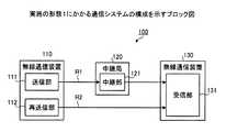
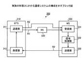
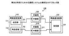
図1は、実施の形態1にかかる通信システムの構成を示すブロック図である。図1に示すように、実施の形態1にかかる通信システム100は、無線通信装置110と、中継局120と、無線通信装置130と、を備える移動通信システムである。無線通信装置110は、無線通信によって無線通信装置130へデータを送信する。(Embodiment 1)
FIG. 1 is a block diagram of a configuration of the communication system according to the first embodiment. As illustrated in FIG. 1, the
また、無線通信装置110と無線通信装置130は、互いにデータを送受信するために複数の経路を利用することができる。たとえば、無線通信装置110と無線通信装置130は、中継局120を介してデータを送受信する第1経路R1と、中継局120を介さずにデータを送受信する第2経路R2と、を利用することができる。 In addition, the
無線通信装置110は、送信部111と、再送信部112と、を備えている。送信部111は、無線通信装置130に対するデータの第1の送信を中継局120による無線中継(第1経路R1)を用いて行う。この場合は、送信部111は、無線通信装置130を宛先とするデータを中継局120へ送信する。ここで、データの第1の送信とは、たとえば、そのデータの無線通信装置130に対する最初の送信である。 The
再送信部112は、送信部111による第1の送信によって送信されたデータの再送信処理を行う。たとえば、再送信部112は、送信部111による第1の送信においてエラーが発生した場合にデータの再送信処理を行う。再送信部112は、中継局(たとえば中継局120)を一切介さないで(第2経路R2)、第1の送信によって送信部111が送信したデータについての再送信処理を行う。 The
再送信処理は、たとえば、第1の送信によってエラーが発生したデータを無線通信装置130側で正常に受信するためのデータを再度送信する処理である。たとえば、再送信処理は、第1の送信によって送信されたデータと同じデータを再度送信する処理である。または、再送信処理は、第1の送信によって送信されたデータの一部(たとえばエラーの該当部分)や、第1の送信によって送信されたデータを含むデータであってもよい。 The retransmission process is a process for retransmitting data for normally receiving data on which an error has occurred due to the first transmission on the
中継局120は、無線通信装置110から無線通信装置130に対するデータの第1の送信を無線中継する。具体的には、中継局120は中継部121を備えている。中継部121は、無線通信装置110から送信されたデータを受信する。そして、中継部121は、受信したデータを無線通信装置130へ送信する。また、中継部121は、無線通信装置110から無線通信装置130に対するデータの再送信を無線中継しない。 The
無線通信装置130は受信部131を備えている。受信部131は、無線通信装置110から中継局120を介して送信されたデータを受信する。また、受信部131は、無線通信装置110から中継局120を介さずに再送信されたデータを受信する。 The
図2は、図1に示した通信システムの変形例を示すブロック図である。図2において、図1に示した構成と同様の構成については同一の符号を付して説明を省略する。図2に示すように、無線通信装置110と無線通信装置130は、中継局120および中継局210を介してデータを送受信する第1経路R1と、中継局120を介さずに中継局210を介してデータを送受信する第2経路R2と、を利用することができるようにしてもよい。 FIG. 2 is a block diagram showing a modification of the communication system shown in FIG. In FIG. 2, the same components as those shown in FIG. As shown in FIG. 2, the
送信部111は、無線通信装置130に対するデータの第1の送信を中継局120および中継局210による無線中継(第1経路R1)を用いて行う。具体的には、送信部111は、無線通信装置130を宛先とするデータを中継局120へ送信する。 The
再送信部112は、第1の送信の際に無線中継を行った中継局に対して少ない総数の中継局を介して、第1の送信によって送信部111が送信したデータについての再送信処理を行う。図2に示した例では、第1の送信の際に無線中継を行った中継局が2つ(中継局120および中継局210)であるため、再送信部112は、無線通信装置130に対するデータの再送信を中継局210による無線中継(第2経路R2)を用いて行う。 The retransmitting
中継局120の中継部121は、無線通信装置110から送信されたデータを受信し、受信したデータを中継局210へ送信する。また、中継部121は、無線通信装置110から無線通信装置130に対するデータの再送信を無線中継しない。 The
中継局210は、無線通信装置110から無線通信装置130へのデータの第1の送信を無線中継する。具体的には、中継局210は中継部211を備えている。中継部211は、中継局120から送信されたデータを受信し、受信したデータを無線通信装置130へ送信する。また、中継部211は、無線通信装置110から無線通信装置130へのデータの再送信を無線中継する。具体的には、中継部211は、無線通信装置110から送信されたデータを受信し、受信したデータを無線通信装置130へ送信する。 The
つぎに、図1および図2に示した無線通信装置110のハードウェア構成の一例について説明する。無線通信装置110の送信部111および再送信部112は、たとえば、CPU(Central Processing Unit)などの情報処理手段および通信インターフェースによって実現される。無線通信装置110のデータ処理部(不図示)は、無線通信装置130へ送信するためのデータを出力する。 Next, an example of the hardware configuration of the
データ処理部から出力されたデータは、無線通信装置110のメモリ(不図示)に書き込まれる。送信部111は、メモリに書き込まれたデータを読み出し、読み出したデータについて第1の送信を行う。再送信部112は、送信部111による第1の送信によって送信されたデータをメモリから読み出し、読み出したデータについて再送信処理を行う。 Data output from the data processing unit is written in a memory (not shown) of the
つぎに、図1および図2に示した中継局120および中継局210のハードウェア構成の一例について説明する。中継局120の中継部121および中継局210の中継部211のそれぞれは、たとえばCPUなどの情報処理手段および通信インターフェースによって実現される。中継部121は、無線通信装置110から受信したデータをデジタル信号に再生し、再生したデータを無線通信装置130へ送信する。 Next, an example of the hardware configuration of the
または、中継部121は、たとえばアナログの増幅回路や波形整形回路および通信インターフェースによって実現されてもよい。中継部121は、無線通信装置110から受信したデータに対して増幅や波形整形などのアナログ処理を行う。中継部121は、アナログ処理を行ったデータを無線通信装置130へ送信する。 Alternatively, the
つぎに、図1および図2に示した無線通信装置130のハードウェア構成の一例について説明する。無線通信装置130の受信部131は、たとえば、CPUなどの情報処理手段および通信インターフェースによって実現される。受信部131は、受信したデータを無線通信装置130(不図示)のメモリに書き込む。メモリに書き込まれたデータは、たとえば、無線通信装置130の情報処理部(不図示)によって読み出されて処理される。 Next, an example of the hardware configuration of the
このように、実施の形態1にかかる通信システム100によれば、第1の送信の際に無線中継を行った中継局の総数に対して少ない総数の中継局を介して、または中継局を一切介さないで、データについての再送信処理を行う。これにより、データの再送信処理を高速化し、再送信処理の発生時におけるデータ伝送の遅延を小さくすることができる。 As described above, according to the
(実施の形態2)
図3は、実施の形態2にかかる通信システムの構成を示すブロック図である。図3に示すように、実施の形態2にかかる通信システム300は、基地局であるBTS310(第1の無線通信装置)と、RS320(中継局)と、移動端末(MS:Mobile Station)であるMS330(第2の無線通信装置)と、を備えている。(Embodiment 2)
FIG. 3 is a block diagram of a configuration of the communication system according to the second embodiment. As shown in FIG. 3, the
BTS310は無線通信によってMS330へデータを送信する。また、BTS310とMS330は、互いにデータを送受信するために複数の経路を利用することができる。たとえば、BTS310とMS330は、RS320を介してデータを送受信する第1経路R1と、RS320を介さずにデータを送受信する第2経路R2と、を利用できる。 The
BTS310は、送信部311と、受信部312と、再送制御部313と、を備えている。送信部311は、MS330に対するデータの第1の送信を第1経路R1により行う。具体的には、送信部311は、MS330に対するデータの第1の送信を行う場合に、MS330を宛先とするデータをRS320へ送信する。また、送信部311は、第1の送信によって送信したデータを図示しないメモリに記憶しておく。 The
また、送信部311は、再送制御部313から再送要求が出力されると、中継局(たとえばRS320)を一切介さないで(第2経路R2)、第1の送信によって送信したデータを再度送信する。具体的には、送信部311は、メモリに記憶しておいたデータを読み出し、読み出したデータをMS330へ直接送信する。また、送信部311は、再送制御部313送信要求が出力されると、新たなデータについて第1の送信を行う。 In addition, when a retransmission request is output from the
受信部312は、MS330によって送信され、RS320によって無線中継された応答信号を受信する。応答信号は、たとえば、BTS310から送信されたデータがMS330によって正常に受信された旨のAck(肯定応答)、または正常に受信されなかった旨のNack(否定応答)のいずれかの信号である。受信部312は、受信した応答信号(AckまたはNack)を再送制御部313へ出力する。 The receiving
再送制御部313は、受信部312から出力された応答信号に応じて、送信部311によるデータの送信および再送信を制御する。具体的には、再送制御部313は、受信部312からAckが出力された場合は、次のデータを送信すべき旨の送信要求を送信部311へ出力する。また、再送制御部313は、受信部312からNackが出力された場合は、送信したデータを再送信すべき旨の再送要求を送信部311へ出力する。 The
RS320は、BTS310からMS330へのデータの第1の送信を無線中継する。また、RS320は、BTS310からMS330へのデータの再送信を無線中継しない。また、RS320は、MS330からBTS310への応答信号を無線中継する。
MS330は、受信部331と、信号処理部332と、送信部333と、を備えている。受信部331は、BTS310からRS320を介して第1の送信として送信されたデータを受信する。また、受信部331は、BTS310からRS320を介さずに再送信されたデータを受信する。受信部331は、受信したデータを復調処理する。そして、受信部331は、復調処理したデータを信号処理部332へ出力する。 The
信号処理部332は、受信部331から出力されたデータの信号処理を行う。たとえば、信号処理部332は、受信部331から出力されたデータの復号処理を行う。また、信号処理部332は、復号処理したデータの誤りを検出する。そして、信号処理部332は、データの誤りの検出結果を送信部333へ通知する。 The
送信部333は、信号処理部332から通知される検出結果に応じてBTS310へ応答信号を送信する。たとえば、信号処理部332から「誤りなし」と通知された場合は、送信部333はBTS310へAckを送信する。また、信号処理部332から「誤りあり」と通知された場合は、送信部333はBTS310へNackを送信する。 The
送信部333は、たとえば、BTS310に対する応答信号の送信をRS320による無線中継(第1経路R1)を用いて行う。具体的には、送信部333は、BTS310を宛先とする応答信号をRS320へ送信する。 For example, the
つぎに、図3に示したBTS310のハードウェア構成の一例について説明する。BTS310の送信部311は、たとえば、CPUなどの情報処理手段および通信インターフェースによって実現される。BTS310のデータ処理部(不図示)は、MS330へ送信するためのデータを出力する。 Next, an example of the hardware configuration of the
データ処理部から出力されたデータは、BTS310のメモリ(不図示)に書き込まれる。送信部311は、メモリに書き込まれたデータを読み出し、読み出したデータについて第1の送信を行う。送信部311は、第1の送信によって送信されたデータをメモリから読み出し、読み出したデータについて再送信処理を行う。 Data output from the data processing unit is written in a memory (not shown) of the
BTS310の受信部312は、たとえば、CPUなどの情報処理手段および通信インターフェースによって実現される。受信部312は、受信した応答信号をBTS310のメモリに書き込む。BTS310の再送制御部313は、たとえば、CPUなどの情報処理手段によって実現される。再送制御部313は、メモリに書き込まれた応答信号に応じて送信部311によるデータの送信および再送信を制御する。 The receiving
つぎに、図3に示したMS330のハードウェア構成の一例について説明する。MS330の受信部331は、たとえば、CPUなどの情報処理手段および通信インターフェースによって実現される。受信部331は、受信したデータをMS330のメモリ(不図示)に書き込む。MS330の信号処理部332は、たとえば、CPUなどの情報処理手段によって実現される。信号処理部332は、受信部331によってメモリに書き込まれたデータを読み出し、読み出したデータの誤りを検出する。 Next, an example of the hardware configuration of the
信号処理部332は、誤りの検出結果をメモリに書き込む。MS330の送信部333は、たとえば、CPUなどの情報処理手段および通信インターフェースによって実現される。送信部333は、信号処理部332によってメモリに書き込まれた誤りの検出結果を読み出し、読み出した検出結果に応じた応答信号をRS320へ送信する。 The
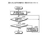
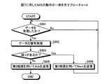
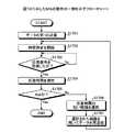
図4は、図3に示したBTSの動作の一例を示すフローチャートである。BTS310は、まず(START)、送信部311により、第1経路R1を用いてMS330へのデータの第1の送信を行う(ステップS401)。つぎに、ステップS401によって送信されたデータに対する応答信号を受信部312が受信したか否かを判断し(ステップS402)、応答信号を受信するまで待つ(ステップS402:Noのループ)。 FIG. 4 is a flowchart showing an example of the operation of the BTS shown in FIG. First (START), the
ステップS402において応答信号を受信すると(ステップS402:Yes)、受信した応答信号がAckであるか否かを判断する(ステップS403)。応答信号がAckでない場合(ステップS403:No)は、送信部311により第2経路R2を用いてデータを再送信し(ステップS404)、ステップS402に戻って処理を続行する。 When a response signal is received in step S402 (step S402: Yes), it is determined whether or not the received response signal is Ack (step S403). When the response signal is not Ack (step S403: No), the
ステップS403において、応答信号がAckである場合(ステップS403:Yes)は一連の処理を終了する(END)。ステップS404によって送信されるデータは、たとえばステップS401によって送信されたデータである。以上のステップを繰り返し行うことにより、たとえば、一連のデータをMS330へ順次送信することができる。 In step S403, when the response signal is Ack (step S403: Yes), the series of processing ends (END). The data transmitted at step S404 is, for example, the data transmitted at step S401. By repeating the above steps, for example, a series of data can be sequentially transmitted to the
また、ステップS404においては、RS320を経由しない第2経路R2を用いてデータを再送信するため、データを再送信してからステップS402によって応答信号を受信するまでの時間を短縮することができる。 In step S404, since the data is retransmitted using the second route R2 that does not pass through the
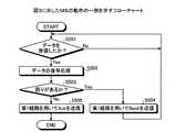
図5は、図3に示したMSの動作の一例を示すフローチャートである。MS330は、まず(START)、BTS310から送信されたデータを受信部331により受信したか否かを判断し(ステップS501)、受信するまで待つ(ステップS501:Noのループ)。データを受信すると(ステップS501:Yes)、受信したデータを信号処理部332により復号処理する(ステップS502)。 FIG. 5 is a flowchart showing an example of the operation of the MS shown in FIG. First, the MS 330 (START) determines whether or not the data transmitted from the
つぎに、信号処理部332により、ステップS502によって復号処理されたデータに誤りがあるか否かを判断する(ステップS503)。データに誤りがある場合(ステップS503:Yes)は、送信部333により、第1経路R1を用いてBTS310へNackを送信し(ステップS504)、ステップS501に戻って処理を続行する。 Next, the
ステップS503において、復号処理されたデータに誤りがない場合(ステップS503:No)は、送信部333により、第1経路R1を用いてBTS310へAckを送信し(ステップS505)、一連の動作を終了する(END)。以上のステップを繰り返し行うことにより、たとえば一連のデータをBTS310から受信することができる。 If there is no error in the decoded data in step S503 (step S503: No), the transmitting
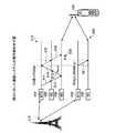
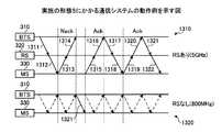
図6は、図3に示した通信システムの動作例を示す図である。図6に示すように、BTS310とMS330は、互いにデータを送受信するために周波数が異なる2つの経路を利用できるとする。2つの経路の一方は、たとえば5GHz帯を使用する第1経路R1であり、2つの経路の他方は、たとえば800MHz帯を使用する第2経路R2である。 FIG. 6 is a diagram illustrating an operation example of the communication system illustrated in FIG. 3. As shown in FIG. 6, it is assumed that the
第1経路R1は、周波数が高く伝搬距離が小さいため、RS320(図3参照)を経由する経路とする。第2経路R2は、周波数が低く伝搬距離が大きいため、RS320を経由しない経路とする。シーケンス図610(RSあり)およびシーケンス図620(RSなし)は時間軸が共通のシーケンス図である。シーケンス図610は、第1経路R1における信号の送受信を示している。シーケンス図620は第2経路R2における信号の送受信を示している。 Since the first route R1 has a high frequency and a short propagation distance, the first route R1 is a route that passes through the RS 320 (see FIG. 3). The second route R2 is a route that does not pass through the
まず、第1経路R1において、BTS310が、第1の送信としてデータをRS320へ送信する(符号611)。つぎに、第1経路R1において、RS320が、BTS310から受信したデータをMS330へ送信する(符号612)。ここで、BTS310とRS320の間またはRS320とMS330の間にエラーが発生し、MS330が受信したデータに誤りが含まれていたとする。 First, in the first route R1, the
つぎに、第1経路R1において、MS330がRS320へNackを送信する(符号613)。つぎに、RS320が、MS330から受信したNackをBTS310へ送信する(符号614)。つぎに、第2経路R2において、BTS310がMS330へデータを再送信する(符号621)。これにより、再送信処理を高速に行うことができる。 Next, in the first route R1, the
なお、符号615および符号616は、BTS310からMS330へのデータの再送新処理を第1経路R1により行う場合のデータの流れを示している。符号615および符号616に示すように、データの再送信に第1経路R1を用いる場合は、BTS310からRS320へデータを送信(符号615)する時間と、RS320からMS330へデータを送信(616)する時間(符号630)と、がかかる。
これに対して、データの再送信に第2経路R2を用いることで(符号621)、BTS310からMS330へデータを直接再送信するため、符号630に示す時間を省くことができる。これにより、データの再送信処理を高速化し、再送信処理の発生時におけるデータ伝送の遅延を小さくすることができる。 On the other hand, by using the second route R2 for data retransmission (reference 621), data is directly retransmitted from the
このように、実施の形態2にかかる通信システム300によれば、第1の送信を行う第1経路R1よりも高速な第2経路R2によって再送信処理を行うことで再送信処理を高速化し、再送信処理の発生時におけるデータ伝送の遅延を小さくすることができる。たとえば、図3に示したように、RS320を経由する経路を第1経路R1とし、RSを一切介さない経路を第2経路R2とすることで、第2経路R2を第1経路R1より高速な経路とすることができる。 As described above, according to the
また、ここでは、データを送信する第1の無線通信装置をBTSに適用し、データを受信する第2の無線通信装置をMSに適用する構成について説明したが、第1の無線通信装置をMSに適用し、第2の無線通信装置をBTSに適用する構成としてもよい。 In addition, here, a configuration has been described in which the first wireless communication apparatus that transmits data is applied to the BTS, and the second wireless communication apparatus that receives data is applied to the MS. The second wireless communication apparatus may be applied to the BTS.
または、第1の無線通信装置をRSに適用し、第2の無線通信装置をMSに適用する構成としたり、第1の無線通信装置をBTSに適用し、第2の無線通信装置をRSに適用する構成としてもよい。また、第1の無線通信装置、中継局、および第2の無線通信装置は、それぞれBTS、RS、およびMSとは異なる無線通信装置に適用してもよい。 Alternatively, the first wireless communication device is applied to the RS, the second wireless communication device is applied to the MS, the first wireless communication device is applied to the BTS, and the second wireless communication device is applied to the RS. It is good also as composition to apply. The first wireless communication device, the relay station, and the second wireless communication device may be applied to wireless communication devices different from BTS, RS, and MS, respectively.
また、MS330は、BTS310の第1の送信によって送信されたデータに誤りがあった場合に、誤りがあったデータの再送の要求信号(Nack)を第1経路R1によりBTS310へ送信する。そして、BTS310は、MS330によって要求信号が送信された場合に再送信処理を行う。これにより、BTS310は、第1の送信によって送信したデータに誤りが発生した場合にデータの再送信処理を行うことができる。 Further, when there is an error in the data transmitted by the first transmission of the
(実施の形態3)
図7は、実施の形態3にかかる通信システムの構成を示すブロック図である。図7において、図3に示した構成と同様の構成については同一の符号を付して説明を省略する。実施の形態3にかかる通信システム300において、MS330の送信部333は、BTS310に対する応答信号の送信をRS320を介さずに(第2経路R2)行ってもよい。(Embodiment 3)
FIG. 7 is a block diagram of a configuration of the communication system according to the third embodiment. In FIG. 7, the same components as those shown in FIG. In the
具体的には、MS330の送信部333は、BTS310に対する応答信号の送信をBTS310へ直接送信する。この場合は、BTS310の受信部312は、MS330によって送信された応答信号を直接受信する。図7に示したBTS310の動作の一例については、図4に示した動作と同様であるため説明を省略する。 Specifically, the
図8は、図7に示したMSの動作の一例を示すフローチャートである。図8に示すステップS801〜S803は、図5に示したステップS501〜S503と同様であるため説明を省略する。ステップS803において、データに誤りがある場合(ステップS803:Yes)は、送信部333により、第2経路R2を用いてBTS310へNackを送信し(ステップS804)、ステップS801に戻って処理を続行する。 FIG. 8 is a flowchart showing an example of the operation of the MS shown in FIG. Steps S801 to S803 shown in FIG. 8 are the same as steps S501 to S503 shown in FIG. If there is an error in the data in step S803 (step S803: Yes), the
ステップS803において、復号処理されたデータに誤りがない場合(ステップS803:No)は、送信部333により、第2経路R2を用いてBTS310へAckを送信し(ステップS805)、一連の動作を終了する(END)。以上のステップを繰り返し行うことにより、たとえば一連のデータをBTS310から受信することができる。 If there is no error in the decoded data in step S803 (step S803: No), the transmitting
また、ステップS804においてはRS320を経由しない第2経路R2を用いてNackを送信するため、Nackを送信してからステップS801によってデータを再度受信するまでの時間を短縮することができる。また、ステップS805においてはRS320を経由しない第2経路R2を用いてAckを送信するため、Ackを送信してからステップS801によって次のデータを受信するまでの時間を短縮することができる。 In step S804, since the Nack is transmitted using the second route R2 that does not pass through the
なお、ここでは、RS320がAckを送信する場合およびRS320がNackを送信する場合に第2経路R2を用いる場合について説明したが、RS320がNackを送信する場合には第2経路R2を用い、RS320がAckを送信する場合には第1経路R1を用いるようにしてもよい。この場合も、Nackを送信してからステップS801によってデータを再度受信するまでの時間を短縮することができる。 In addition, although the case where the second path R2 is used when the
図9は、図7に示した通信システムの動作例を示す図である。図9に示すように、BTS310とMS330は、互いにデータを送受信するために周波数が異なる2つの経路を利用できるとする。2つの経路の一方は、たとえば5GHz帯を使用する第1経路R1であり、2つの経路の他方は、たとえば800MHz帯を使用する第2経路R2である。 FIG. 9 is a diagram illustrating an operation example of the communication system illustrated in FIG. 7. As shown in FIG. 9, it is assumed that the
第1経路R1は、周波数が高く伝搬距離が小さいため、RS320(図7参照)を経由する経路とする。第2経路R2は、周波数が低く伝搬距離が大きいため、RS320を経由しない経路とする。シーケンス図910(RSあり)およびシーケンス図920(RSなし)は、時間軸が共通のシーケンス図である。シーケンス図910は、第1経路R1における信号の送受信を示し、シーケンス図920は第2経路R2における信号の送受信を示している。 Since the first route R1 has a high frequency and a short propagation distance, the first route R1 is a route that passes through the RS 320 (see FIG. 7). The second route R2 is a route that does not pass through the
まず、第1経路R1において、BTS310が、RS320へデータを送信する(符号911)。つぎに、第1経路R1において、RS320が、BTS310から受信したデータをMS330へ無線中継する(符号912)。ここで、MS330が受信したデータに誤りが含まれていたとする。つぎに、第2経路R2において、MS330がBTS310へNackを送信する(符号921)。つぎに、第2経路R2において、BTS310がMS330へデータを再送信する(符号922)。 First, in the first route R1, the
なお、符号913〜916は、MS330によるNackの送信と、BTS310によるデータの再送信と、を第1経路R1により行う場合のデータの流れを示している。符号913,914に示すように、Nackの送信に第1経路R1を用いる場合は、MS330からRS320へNackを送信(符号913)する時間と、RS320からBTS310へNackを送信(符号914)する時間(符号931)と、がかかる。
これに対して、Nackの送信に第2経路R2を用いることで(符号921)、MS330からBTS310へNackを直接送信するため、符号931に示す時間を省くことができる。これにより、データの再送信処理を高速化し、再送信処理の発生時におけるデータ伝送の遅延を小さくすることができる。 On the other hand, since the Nack is directly transmitted from the
また、符号915,916に示すように、データの再送信に第1経路R1を用いる場合は、BTS310からRS320へデータを送信(符号915)する時間と、RS320からMS330へデータを送信(符号916)する時間(符号932)と、がかかる。 In addition, as indicated by
これに対して、データの再送信に第2経路R2を用いることで(符号922)、BTS310からMS330へデータを直接再送信するため、符号932に示す時間を省くことができる。これにより、データの再送信処理を高速化し、再送信処理の発生時におけるデータ伝送の遅延を小さくすることができる。 On the other hand, by using the second route R2 for data retransmission (reference 922), data is directly retransmitted from the
このように、実施の形態3にかかる通信システム300によれば、BTS310の第1の送信によって送信されたデータに誤りがあった場合に、誤りがあったデータの再送の要求信号(Nack)を第2経路R2によってBTS310へ送信する。そして、BTS310は、MS330によって要求信号が送信された場合に再送信処理を行う。 As described above, according to the
これにより、MS330からBTS310への再送の要求信号(Nack)の伝送にかかる時間を短縮することができる。このため、実施の形態3にかかる通信システム300によれば、実施の形態2にかかる通信システム300と同様の効果を奏するとともに、再送信処理の発生時におけるデータ伝送の遅延をさらに小さくすることができる。 As a result, it is possible to reduce the time required for transmission of the retransmission request signal (Nack) from the
(実施の形態4)
図10は、実施の形態4にかかる通信システムの構成を示すブロック図である。図10において、図3に示した構成と同様の構成については同一の符号を付して説明を省略する。たとえば、BTS310とMS330は、RS320およびRS1011を介してデータを送受信する第1経路R1(無線中継数2)と、RS1012を介してデータを送受信する第2経路R2(無線中継数1)と、を利用することができる。(Embodiment 4)
FIG. 10 is a block diagram of a configuration of a communication system according to the fourth embodiment. 10, the same components as those illustrated in FIG. 3 are denoted by the same reference numerals, and the description thereof is omitted. For example, the
RS320は、MS330を宛先としてBTS310から送信されたデータをRS1011へ無線中継する。RS1011は、MS330を宛先としてRS320から送信されたデータをMS330へ無線中継する。RS1012は、MS330を宛先としてBTS310から送信されたデータをMS330へ無線中継する。 The
RS320、RS1011およびRS1012のそれぞれは、自局からMS330までの無線中継数を前段の通信装置へ通知する。たとえば、RS320は、RS320からMS330までの無線中継数をBTS310へ通知する。また、RS1011は、MS330からRS1011までの無線中継数をRS320へ通知する。また、RS1012は、MS330からRS1012までの無線中継数をBTS310へ通知する。無線中継数の通知は、たとえば、移動通信網のコントロールチャネルを用いて行う。 Each of
BTS310の受信部312は、RS320によって通知された無線中継数を第1経路R1の無線中継数として受信する。また、受信部312は、RS1012によって通知された無線中継数を第2経路R2の無線中継数として受信する。受信部312は、受信した第1経路R1および第2経路R2の各無線中継数を再送制御部313へ出力する。 The receiving
再送制御部313は、受信部312から出力された第1経路R1および第2経路R2の各無線中継数を比較する。そして、再送制御部313は、第1経路R1および第2経路R2のうちの無線中継数が少ない経路を再送信に用いる経路として送信部311へ通知する。送信部311は、第1の送信によって送信部311が送信したデータについての再送信処理を、再送制御部313から通知された経路によって行う。 The
なお、RS320、RS1011およびRS1012のそれぞれが無線中継数を前段の通信装置へ通知するタイミングは、たとえば、BTS310からMS330へのデータを無線中継するタイミングである。この場合に、第1経路R1および第2経路R2の各無線中継数を取得するためには、たとえば、初期動作において、送信部311が、MS330に対するデータの第1の送信を、第1経路R1および第2経路R2を用いて行う。 Note that the timing at which each of the
たとえば、送信部311は、MS330に対する第1データの第1の送信を第1経路R1により行う。また、送信部311は、MS330に対する第2データ(第1データの次のデータ)の第1の送信を第2経路R2により行う。これにより、BTS310は、第1経路R1および第2経路R2の各無線中継数を取得することができ、その後に再送信処理を行う場合に、無線中継数が少ない経路を選択することができる。 For example, the
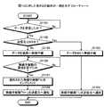
図11は、図10に示した各RSの動作の一例を示すフローチャートである。まず(START)、BTS310から送信され、MS330を宛先とするデータを受信したか否かを判断し(ステップS1101)、データを受信するまで待つ(ステップS1101:Noのループ)。データを受信すると(ステップS1101:Yes)、受信したデータの自局による送信先がMS330か否かを判断する(ステップS1102)。 FIG. 11 is a flowchart illustrating an example of the operation of each RS illustrated in FIG. First (START), it is determined whether or not data transmitted from the
ステップS1102において、送信先がMS330である場合(ステップS1102:Yes)は、ステップS1101によって受信されたデータをMS330へ無線中継する(ステップS1103)。つぎに、ステップS1101によって受信されたデータの送信元へ無線中継数「1」を通知し(ステップS1104)、一連の処理を終了する。 In step S1102, if the transmission destination is the MS 330 (step S1102: Yes), the data received in step S1101 is wirelessly relayed to the MS 330 (step S1103). Next, the number of wireless relays “1” is notified to the transmission source of the data received in step S1101 (step S1104), and the series of processing ends.
ステップS1102において、送信先がMS330でない場合(ステップS1102:No)は、ステップS1101によって受信されたデータを自局の後段へ無線中継する(ステップS1105)。つぎに、ステップS1105におけるデータの送信先から無線中継数の通知を受けたか否かを判断し(ステップS1106)、無線中継数の通知を受けるまで待つ(ステップS1106:Noのループ)。 In step S1102, if the transmission destination is not the MS 330 (step S1102: No), the data received in step S1101 is wirelessly relayed to the subsequent stage of the own station (step S1105). Next, it is determined whether or not a notification of the number of wireless relays has been received from the data transmission destination in step S1105 (step S1106), and waits until a notification of the number of wireless relays is received (step S1106: No loop).
ステップS1106において、無線中継数の通知を受けると(ステップS1106:Yes)、通知された無線中継数「N」をインクリメントする(ステップS1107)。つぎに、ステップS1101によって受信されたデータの送信元へ、ステップS1107によってインクリメントされた無線中継数「N+1」を通知し(ステップS1108)、一連の処理を終了する。 In step S1106, when a notification of the number of wireless relays is received (step S1106: Yes), the notified number of wireless relays “N” is incremented (step S1107). Next, the number of wireless relays “N + 1” incremented in step S1107 is notified to the transmission source of the data received in step S1101 (step S1108), and the series of processing ends.
図10に示したRS320、RS1011およびRS1012のそれぞれが以上のステップを繰り返し行うことにより、BTS310からMS330へのデータを無線中継することができる。また、以上のステップにより、第1経路R1および第2経路R2の各無線中継数をBTS310へ通知することができる。 Each of
図12は、図10に示した通信システムの動作例を示す図である。最初に、図10に示した第1経路R1(RS320とRS1011を経由)における無線中継数の通知について説明する。まず、BTS310がRS320へデータ(data)を送信する。つぎに、RS320が、BTS310から送信されたデータをRS1011へ無線中継する。 FIG. 12 is a diagram illustrating an operation example of the communication system illustrated in FIG. 10. First, the notification of the number of wireless relays in the first route R1 (via RS320 and RS1011) shown in FIG. 10 will be described. First, the
つぎに、RS1011は、RS320から送信されたデータをMS330へ無線中継する。また、RS1011は、受信したデータのRS1011による送信先がMS330であるため、データの送信元のRS320へ無線中継数「1」を通知する。つぎに、RS320は、RS1011から通知された無線中継数「1」をインクリメントし、インクリメントした無線中継数「2」をBTS310へ通知する。これにより、BTS310は、第1経路R1の無線中継数「2」を取得することができる。 Next, the
続いて、図10に示した第2経路R2(RS1012を経由)における無線中継数の通知について説明する。まず、BTS310がRS1012へデータを送信する。つぎに、RS1012が、BTS310から送信されたデータをMS330へ無線中継する。また、RS1012は、受信したデータのRS1012による送信先がMS330であるため、データの送信元のBTS310へ無線中継数「1」を通知する。 Next, notification of the number of wireless relays on the second route R2 (via RS 1012) illustrated in FIG. 10 will be described. First, the
これにより、BTS310は、第2経路R2の無線中継数「1」を取得することができる。したがって、BTS310は、第1経路R1および第2経路R2の各無線中継数を取得することができる。この場合に、BTS310の送信部311は、第1の送信によって送信したデータについての再送信処理を、無線中継数が第1経路R1より少ない第2経路R2によって行う。 As a result, the
このように、実施の形態4にかかる通信システム300によれば、第1の送信を行う第1経路R1よりも高速な第2経路R2によって再送信処理を行うことで再送信処理を高速化し、再送信処理の発生時におけるデータ伝送の遅延を小さくすることができる。たとえば、図10に示したように、RSを複数経由する経路を第1経路R1とし、第1経路R1よりも少ないRSを経由する経路を第2経路R2とすることで、第2経路R2を第1経路R1よりも高速な経路とする。 As described above, according to the
また、RS320、RS1011およびRS1012のそれぞれが、自局からMS330までの無線中継数を前段の中継局またはBTS310へ通知し、BTS310は、データの再送信処理を、通知された無線中継数が少ない経路によって行う。これにより、BTS310は、第1の送信を行う第1経路R1よりもRSの経由数が少ない経路を、再送信処理を行う第2経路R2として選択することができる。 Further, each of
このため、実施の形態2にかかる通信システム300と同様の効果を奏するとともに、RSなどの中継局を一切介さない経路が存在しない場合でも再送信処理を高速化することができる。または、中継局を一切介さない経路が存在しても通信品質が確保できず利用できない場合などでも、再送信処理を高速化することができる。 Therefore, the same effects as those of the
(実施の形態5)
図13は、実施の形態5にかかる通信システムの動作例を示す図である。図13に示すように、BTS310とMS330は、互いにデータを送受信するために、周波数の異なる複数の経路を同時に利用する周波数アグリゲーションを行ってもよい。この場合の通信システム300の構成については、図3に示した構成と同様であるため図示を省略する。(Embodiment 5)
FIG. 13 is a diagram of an operation example of the communication system according to the fifth embodiment. As shown in FIG. 13, the
図13に示すように、BTS310は、RS320を経由する第1経路R1と、RSを一切経由しない第2経路R2と、を同時に用いてMS330へのデータの第1の送信を行っている。具体的には、BTS310の送信部311は、第1の送信として送信する各データを第1経路R1と第2経路R2に割り振る。以下、送信部311が第1経路R1に割り振ったデータのリンクを第1リンクと称し、第2経路R2に割り振ったデータのリンクを第2リンクと称する。 As shown in FIG. 13, the
シーケンス図1310(RSあり)およびシーケンス図1320(RSなし)は、時間軸が共通のシーケンス図である。シーケンス図1310は、第1経路R1における信号の送受信を示している。シーケンス図1320は第2経路R2における信号の送受信を示している。シーケンス図1310およびシーケンス図1320において、実線矢印は第1リンクのデータの流れを示し、一転鎖線矢印は第2リンクのデータの流れを示している。 Sequence diagram 1310 (with RS) and sequence diagram 1320 (without RS) are sequence diagrams having a common time axis. A sequence diagram 1310 shows signal transmission and reception in the first route R1. A sequence diagram 1320 shows signal transmission and reception in the second route R2. In the sequence diagram 1310 and the sequence diagram 1320, the solid arrow indicates the data flow of the first link, and the alternate long and short dash line indicates the data flow of the second link.
シーケンス図1310およびシーケンス図1320に示すように、BTS310は、第1リンクのデータを第1経路R1により送信し、第2リンクのデータを第2経路R2により送信する。また、BTS310は、第1経路R1を用いて第1の送信を行った第1リンクのデータの再送信処理を、第2経路R2を用いた第2リンクのデータの第1の送信に割り込ませて行う。 As shown in the sequence diagram 1310 and the sequence diagram 1320, the
まず、第1経路R1において、BTS310が、RS320へデータを送信する(符号1311)。つぎに、RS320が、BTS310から受信したデータをMS330へ送信する(符号1312)。ここで、MS330が受信したデータに誤りが含まれていたとする。つぎに、MS330がRS320へNackを送信する(符号1313)。 First, in the first route R1, the
つぎに、RS320が、MS330から受信したNackをBTS310へ送信する(符号1314)。つぎに、第2経路R2において、BTS310が、同時に行っている第2リンクのデータの送信に割り込ませて、Nackを受信した第1リンクのデータの再送信処理を行う(符号1321)。ここで、BTS310によって再送信され、MS330が再受信したデータには誤りが含まれていなかったとする。 Next, the
つぎに、MS330が、BTS310から受信したデータのAckをRS320へ送信する(符号1315)。つぎに、RS320が、MS330から受信したAckをBTS310へ送信する(符号1316)。つぎに、BTS310が、新たなデータをRS320へ送信する(符号1317)。つぎに、RS320が、BTS310から受信したデータをMS330へ送信する(符号1318)。ここで、MS330が受信したデータには誤りが含まれていなかったとする。 Next, the
つぎに、MS330が、RS320から受信したデータのAckをRS320へ送信する(符号1319)。以降、符号1320〜1322に示す動作は、符号1316〜1318に示した動作と同様であるため説明を省略する。データの再送信に第2経路R2を用いることで(符号1321)、データの再送信処理を高速化し、再送信処理の発生時におけるデータ伝送の遅延を小さくすることができる。 Next, the
このように、実施の形態5にかかる通信システム300によれば、第1経路R1を用いて第1の送信を行った第1リンクのデータの再送信処理を、第2経路R2を用いた第2リンクの第1の送信に割り込ませて行う。これにより、第1の送信を行う第1経路R1よりも高速な第2経路R2によって再送信処理を行うことができる。このため、複数の経路を同時に利用して第1の送信を行う通信システム(周波数アグリゲーションなど)においても、再送信処理を高速化し、再送信処理の発生時におけるデータ伝送の遅延を小さくすることができる。 As described above, according to the
(実施の形態6)
図14は、実施の形態6にかかる通信システムの構成を示すブロック図である。実施の形態6において、実施の形態2と同様の部分については説明を省略する。実施の形態6にかかる通信システム300においては、BTS310は、MS330へデータを送信するとともに、MS330とは異なるMS1401へデータを送信する構成としてもよい。(Embodiment 6)
FIG. 14 is a block diagram of a configuration of a communication system according to the sixth embodiment. In the sixth embodiment, description of the same parts as those in the second embodiment is omitted. In the
この場合は、BTS310は、MS1401へ送信するデータについても、第1の送信を行う場合は第1経路R1を用い、再送信処理を行う場合は第2経路R2を用いる。シーケンス図1410(RSあり)、シーケンス図1420(RSあり)およびシーケンス図1430(RSなし)は、時間軸が共通のシーケンス図である。 In this case, the
シーケンス図1410、シーケンス図1420およびシーケンス図1430において、実線矢印はBTS310とMS330の間の信号の流れを示し、一転鎖線矢印はBTS310とMS1401の間の信号の流れを示している。シーケンス図1410は、BTS310とMS330の間の第1経路R1における信号の送受信を示している。 In the sequence diagram 1410, the sequence diagram 1420, and the sequence diagram 1430, a solid line arrow indicates a signal flow between the
シーケンス図1420は、BTS310とMS1401の間の第1経路R1における信号の送受信を示している。シーケンス図1430は、BTS310とMS330の間と、BTS310とMS1401の間との第2経路R2における信号の送受信を示している。 A sequence diagram 1420 shows signal transmission / reception between the
まず、第1経路R1において、BTS310が、MS1401を宛先とするデータをRS320へ送信する(符号1421)。つぎに、RS320が、BTS310から受信したデータをMS1401へ無線中継する(符号1422)。ここで、MS1401が受信したデータに誤りが含まれていたとする。 First, in the first route R1, the
つぎに、第2経路R2において、MS1401がBTS310へNackを送信する(符号1431)。つぎに、第2経路R2において、BTS310がMS1401へデータを再送信する(符号1432)。つぎに、第1経路R1において、BTS310が、MS330を宛先とするデータをRS320へ送信する(符号1411)。つぎに、RS320が、BTS310から受信したデータをMS330へ無線中継する(符号1412)。 Next, in the second route R2, the
ここで、MS330が受信したデータに誤りが含まれていたとする。つぎに、第2経路R2において、MS330がBTS310へNackを送信する(符号1433)。つぎに、第2経路R2において、BTS310がMS330へデータを再送信する(符号1434)。ここで、MS330が受信したデータに誤りが含まれていなかったとする。 Here, it is assumed that the data received by the
また、このとき、第1経路R1において、BTS310が、MS1401を宛先とするデータをRS320へ送信する(符号1423)。つぎに、RS320が、BTS310から受信したデータをMS1401へ無線中継する(符号1424)。ここで、MS1401が受信したデータに誤りが含まれていなかったとする。つぎに、第2経路R2において、MS1401がBTS310へAckを送信する(符号1435)。 At this time, in the first route R1, the
また、このとき、第1経路R1において、BTS310が、MS330を宛先とするデータをRS320へ送信する(符号1413)。つぎに、RS320が、BTS310から受信したデータをMS330へ無線中継する(符号1414)。ここで、MS330が受信したデータに誤りが含まれていなかったとする。つぎに、第2経路R2において、MS330がBTS310へAckを送信する(符号1436)。 At this time, in the first route R1, the
以降、同様に、BTS310は、MS330およびMS1401に対する第1の送信を第1経路R1により行いつつ、MS330およびMS1401に対する再送信処理は第2経路R2により行う。このため、BTS310とMS330の間の再送信処理と、BTS310とMS1401の間の再送信処理と、により第2経路R2の通信資源を共用することができる。 Thereafter, similarly, the
このように、実施の形態6にかかる通信システム300によれば、実施の形態2にかかる通信システム300と同様の効果を奏するとともに、BTS310は、複数のMSとの間のデータの送受信において、各MSに対する再送信処理をともに第2経路R2によって行うことができる。これにより、各MSとの間の各通信における再送信処理を高速化し、再送信処理の発生時におけるデータ伝送の遅延を小さくすることができる。 As described above, according to the
(実施の形態7)
図15は、実施の形態7にかかる通信システムの構成を示すブロック図である。図15において、図1に示した構成と同様の構成については同一の符号を付して説明を省略する。図15に示すように、無線通信装置110と無線通信装置130は、中継局120を介してデータを送受信する第1経路R1と、中継局210を介してデータを送受信する第2経路R2と、を利用することができるようにしてもよい。(Embodiment 7)
FIG. 15 is a block diagram of a configuration of a communication system according to the seventh embodiment. In FIG. 15, the same components as those shown in FIG. As illustrated in FIG. 15, the
再送信部112は、送信部111による第1の送信の際の中継経路(第1経路R1)に含まれる各中継局内における中継処理時間の総和に対して、同じデータについての再送信の際に中継経路に含まれる各中継局内における中継処理時間の総和が小さくなる経路で再送信処理を行う。たとえば、図15に示した例において、第1経路R1に含まれる中継局120におけるデータの中継処理時間が、第2経路R2に含まれる中継局210におけるデータの中継処理時間よりも大きいとする。 The retransmitting
この場合は、再送信部112は、送信部111による第1の送信によって送信したデータの再送信処理を第2経路R2により行う。中継局120は、無線通信装置130を宛先として無線通信装置110から送信されたデータを無線通信装置130へ無線中継する。 In this case, the
このように、実施の形態7にかかる通信システム100によれば、第1の送信の際の中継経路(第1経路R1)に含まれる各中継局内における中継処理時間の総和に対して、同じデータについての再送信の際に中継経路に含まれる各中継局内における中継処理時間の総和が小さくなる経路で再送信処理を行う。これにより、データの再送信処理を高速化し、再送信処理の発生時におけるデータ伝送の遅延を小さくすることができる。 As described above, according to the
(実施の形態8)
図16は、実施の形態8にかかる通信システムの構成を示すブロック図である。図16において、図3に示した構成と同様の構成については同一の符号を付して説明を省略する。実施の形態8において、たとえば、BTS310とMS330は、RS320を介してデータを送受信する第1経路R1と、RS1620を介してデータを送受信する第2経路R2と、を利用することができるようにしてもよい。(Embodiment 8)
FIG. 16 is a block diagram of a configuration of a communication system according to the eighth embodiment. 16, the same components as those shown in FIG. 3 are denoted by the same reference numerals and description thereof is omitted. In the eighth embodiment, for example, the
BTS310は、図3に示した構成に加えて測定部1611を備えている。測定部1611は、第1経路R1および第2経路R2のそれぞれにつき、送信部311による第1の送信から、第1の送信に対するMS330からの応答信号を受信するまでの応答時間を測定する。測定部1611は、測定した各経路の応答時間を再送制御部313へ出力する。 The
再送制御部313は、測定部1611から出力された第1経路R1および第2経路R2について測定された各時間を比較する。そして、再送制御部313は、第1経路R1および第2経路R2のうちの測定された時間が短い経路を再送信に用いる経路として送信部311へ通知する。送信部311は、第1の送信に送信したデータについての再送信処理を、再送制御部313から通知された経路によって行う。 The
つぎに、測定部1611による応答時間の測定方法について説明する。たとえば、送信部311は、第1の送信を行うときに測定部1611へ測定開始信号を出力する。また、受信部312は、MS330からの応答信号を受信したときに測定部1611へ測定終了信号を出力する。測定部1611は、送信部311により測定開始信号が出力されてから、受信部312により測定終了信号が出力されるまでの時間を応答時間として測定する。 Next, a method for measuring response time by the
また、測定部1611が第1経路R1および第2経路R2の各応答時間を測定するためには、たとえば、初期動作において、BTS310の送信部311が、MS330に対するデータの第1の送信を、第1経路R1および第2経路R2を用いて行う。たとえば、送信部311は、MS330に対する第1データの第1の送信を第1経路R1により行う。 Further, in order for the
また、送信部311は、MS330に対する第2データ(第1データの次のデータ)の第1の送信を第2経路R2により行う。これにより、測定部1611は、第1経路R1および第2経路R2の各応答時間を取得することができる。このため、BTS310は、その後にデータの再送を行う場合に、応答時間が短い経路を選択することができる。 Further, the
つぎに、図16に示したBTS310の測定部1611のハードウェア構成の一例について説明する。測定部1611は、たとえば、CPUなどの情報処理手段によって実現される。測定部1611は、測定した応答時間をBTS310のメモリ(不図示)に書き込む。BTS310の再送制御部313は、測定部1611によってメモリに書き込まれた応答時間を読み出し、読み出した応答時間に基づいて再送制御を行う。 Next, an example of the hardware configuration of the
図17は、図16に示したMSの動作の一例を示すフローチャートである。図16に示したBTS310は、まず(START)、送信部311により第1経路R1を用いてMS330へのデータの第1の送信を行う(ステップS1701)。つぎに、測定部1611により時間測定を開始する(ステップS1702)。 FIG. 17 is a flowchart showing an example of the operation of the MS shown in FIG. The
つぎに、ステップS1701によって送信されたデータに対する応答信号を受信部312が受信したか否かを判断し(ステップS1703)、応答信号を受信するまで待つ(ステップS1703:Noのループ)。応答信号を受信すると(ステップS1703:Yes)、測定部1611により、ステップS1702によって時間測定を開始してからの経過時間を応答時間として測定する(ステップS1704)。 Next, it is determined whether or not the
つぎに、ステップS1703によって受信された応答信号がAckであるか否かを判断する(ステップS1705)。ステップS1705において応答信号がAckでない場合(ステップS1705:No)は、ステップS1704によって測定された応答時間の短い伝送時間の短い経路を選択する(ステップS1706)。 Next, it is determined whether or not the response signal received in step S1703 is Ack (step S1705). If the response signal is not Ack in step S1705 (step S1705: No), a route with a short transmission time measured in step S1704 is selected (step S1706).
つぎに、ステップS1706によって選択された経路を用いて送信部311によりデータを再送信し(ステップS1707)、ステップS1702に戻って処理を続行する。ステップ1705において、応答信号がAckである場合(ステップS1705:Yes)は一連の処理を終了する(END)。ステップS1707によって送信されるデータは、たとえばステップS1701によって送信されたデータである。 Next, data is retransmitted by the
以上のステップを繰り返し行うことにより、たとえば一連のデータをMS330へ送信することができる。また、ステップS1704においてはRS320を経由しない第2経路R2を用いてデータを再送信するため、データを再送信してからステップS1703によって応答信号を受信するまでの時間を短縮することができる。 By repeating the above steps, for example, a series of data can be transmitted to the
また、ステップS1701からステップS1704までの時間を測定部1611により測定することで、第1の送信において用いた経路の応答時間を測定することができる。これにより、第1経路R1に含まれる各RS内における中継処理時間の総和と、第2経路R2に含まれる各中継局内における中継処理時間の総和と、を測定することができる。 Further, by measuring the time from step S1701 to step S1704 by the
図18は、図16に示した通信システムの動作例を示す図である。シーケンス図1800は、第1経路R1における信号の送受信を示している。まず、BTS310がRS320へデータを送信する(符号1811)。つぎに、RS320が、BTS310から送信されたデータをMS330へ無線中継する(符号1812)。 FIG. 18 is a diagram illustrating an operation example of the communication system illustrated in FIG. 16. A sequence diagram 1800 shows signal transmission and reception in the first route R1. First, the
つぎに、MS330がRS320へ応答信号を送信する(符号1813)。つぎに、RS320が、MS330から受信した応答信号をBTS310へ送信する(符号1814)。BTS310の測定部1611は、BTS310がMS330へのデータを送信(符号1811)してから、MS330からの応答信号をBTS310が受信(符号1814)するまでの時間1820を測定する。 Next, the
このように、実施の形態8にかかる通信システム300によれば、第1の送信を行う第1経路R1よりも高速な第2経路R2によって再送信処理を行うことで再送信処理を高速化し、再送信処理の発生時におけるデータ伝送の遅延を小さくすることができる。たとえば、図16に示したように、各経路の応答時間をそれぞれ測定し、測定した時間が短い経路を第2経路R2とすることで、第2経路R2を第1経路R1よりも高速な経路とする。 As described above, according to the
また、各経路について、BTS310がMS330へのデータを送信(符号1811)してから、MS330からの応答信号をBTS310が受信(符号1814)するまでの時間1820を測定する。これにより、各経路の応答時間を測定することができる。このため、BTS310は、第1の送信を行う第1経路R1よりも応答時間が短い経路を、再送信処理を行う第2経路R2として選択することができる。 For each path, a
このため、実施の形態2にかかる通信システム300と同様の効果を奏するとともに、RSなどの中継局を一切介さない経路が存在しない場合でも再送信処理を高速化することができる。または、中継局を一切介さない経路が存在しても通信品質が確保できず利用できない場合などでも、再送信処理を高速化することができる。 Therefore, the same effects as those of the
(実施の形態9)
図19は、実施の形態9にかかる通信システムの構成を示すブロック図である。図19において、図3に示した構成と同様の構成については同一の符号を付して説明を省略する。実施の形態9にかかる通信システム300においては、BTS310およびRS320の間、RS320とMS330の間でそれぞれ独立して再送制御を行う。(Embodiment 9)
FIG. 19 is a block diagram of a configuration of a communication system according to the ninth embodiment. In FIG. 19, the same components as those shown in FIG. In the
送信部311は、RS320を経由する第1経路R1と、RSを一切経由しない第2経路R2と、を同時に用いてMS330へのデータの第1の送信を行っている。具体的には、送信部311は、第1の送信として送信する各データを第1経路R1と第2経路R2に割り振る。以下、送信部311が第1経路R1に割り振ったデータのリンクを第1リンクと称し、第2経路R2に割り振ったデータのリンクを第2リンクと称する。 The
送信部311は、第1リンクのデータを送信する場合は、データをRS320へ送信する。また、送信部311は、第2リンクのデータを送信する場合は、データをMS330へ直接送信する。また、送信部311は、再送制御部313から再送要求が出力されると、中継局(たとえばRS320)を一切介さないで(第2経路R2)、第1の送信によって送信したデータを再度送信する。また、送信部311は、再送制御部313から送信要求が出力されると、新たなデータについて第1の送信を行う。 When transmitting the first link data, the
RS320は、MS330との間で再送制御を行う機能を有する。具体的には、RS320は、受信部1911と、信号処理部1912と、送信部1913と、送信部1921と、受信部1922と、再送制御部1923と、を備えている。受信部1911は、BTS310から第1の送信として送信されたデータを受信する。受信部1911は、受信したデータを復調処理し、復調処理したデータを信号処理部1912へ出力する。 The
信号処理部1912は、受信部1911から出力されたデータの信号処理を行う。たとえば、信号処理部1912は、受信部1911から出力されたデータの復号処理を行う。また、信号処理部1912は、復号処理したデータの誤りを検出し、検出結果を送信部1913へ通知する。また、信号処理部1912は、データの誤りがなかった場合は、信号処理したデータをRS320のバッファ(不図示)に格納する。 The
送信部1913は、信号処理部1912から通知される検出結果に応じてBTS310へ応答信号を送信する。たとえば、送信部1913は、信号処理部1912から「誤りなし」と通知された場合はBTS310へAckを送信し、信号処理部1912から「誤りあり」と通知された場合はBTS310へNackを送信する。 The
送信部1921は、信号処理部1912によってRS320送信バッファに格納されたデータを読み出す。そして、送信部1921は、読み出したデータを第1の送信としてMS330へ送信する。また、送信部1921は、第1の送信によって送信したデータを図示しないメモリに記憶しておく。 The
また、送信部1921は、再送制御部1923から再送要求が出力されると、第1の送信によって送信したデータを再度送信する。具体的には、送信部1921は、メモリに記憶しておいたデータを読み出し、読み出したデータをMS330へ送信する。また、送信部1921は、再送制御部1923から送信要求が出力されると、信号処理部1912から出力された次のデータについて第1の送信を行う。 In addition, when a retransmission request is output from the
受信部1922は、MS330によって送信された応答信号を受信する。応答信号は、たとえばRS320から送信されたデータがMS330によって正常に受信された旨のAck、または正常に受信されなかった旨のNackのいずれかの信号である。受信部1922は、受信した応答信号を再送制御部1923へ出力する。 The receiving
再送制御部1923は、送信部1921によるデータの再送信を制御する。具体的には、再送制御部1923は、受信部1922からAckが出力された場合は、Ackに対応したデータを送信バッファから消去し、次のデータを送信すべき旨の送信要求を送信部1921へ出力する。また、再送制御部1923は、受信部1922からNackが出力された場合は、送信したデータを再送信すべき旨の再送要求を送信部1921へ出力する。 The
MS330の信号処理部332は、データの誤り検出の結果を送信部333へ通知するとともに、そのデータが第1経路R1および第2経路R2のいずれによって送信されたデータかを送信部333へ通知する。 The
MS330の送信部333は、第1経路R1によって送信されたデータについて信号処理部332から検出結果が通知された場合は、検出結果が「誤りあり」でも「誤りなし」でもRS320に対してはAckを送信する。MS330の送信部333は、BTS310に対しては、検出結果が「誤りなし」である場合は第2経路R2を用いてAckを送信し、検出結果が「誤りあり」である場合は第2経路R2を用いてNackを送信する。 When the detection result is notified from the
また、送信部333は、第2経路R2によって送信されたデータについて信号処理部332から検出結果が通知された場合は、検出結果に応じてBTS310へ応答信号を第2経路R2により送信する。たとえば、信号処理部332から「誤りなし」と通知された場合は、送信部333はBTS310へAckを送信する。また、信号処理部332から「誤りあり」と通知された場合は、送信部333はBTS310へNackを送信する。 Further, when the detection result is notified from the
つぎに、図19に示したRS320のハードウェア構成の一例について説明する。RS320の受信部1911、送信部1913、送信部1921および受信部1922は、たとえば、CPUなどの情報処理手段および通信インターフェースによって実現される。RS320の信号処理部1912および再送制御部は、たとえば、CPUなどの情報処理手段および通信インターフェースによって実現される。 Next, an example of the hardware configuration of the
受信部1911は、受信したデータをRS320のメモリに書き込む。信号処理部1912は、受信部1911によってメモリに書き込まれたデータを読み出し、読み出したデータについて信号処理を行う。信号処理部1912は、誤り検出結果およびデータをRS320のメモリに書き込む。送信部1913は、信号処理部1912によってRS320のメモリに書き込まれた検出結果に応じた応答信号を送信する。 The receiving
送信部1921は、信号処理部1912によってRS320のメモリに書き込まれたデータを読み出し、読み出したデータを送信する。受信部1922は、受信した応答信号をRS320のメモリに書き込む。RS320の再送制御部1923は、受信部1922によってメモリに書き込まれた応答信号に応じて再送制御を行う。 The
図20は、図19に示したMSの動作の一例を示すフローチャートである。MS330は、まず(START)、第1経路R1または第2経路R2によって送信されたデータを受信部331により受信したか否かを判断し(ステップS2001)、受信するまで待つ(ステップS2001:Noのループ)。データを受信すると(ステップS2001:Yes)、受信されたデータについて、第1経路R1から受信したか否かを判断する(ステップS2002)。 FIG. 20 is a flowchart showing an example of the operation of the MS shown in FIG. The
ステップS2002において、第1経路R1から受信した場合(ステップS2002:Yes)は、ステップS2001によって受信したデータの復号処理を信号処理部332により行う(ステップS2003)。つぎに、第1経路R1を用いてRS320へAckを送信し(ステップS2004)、ステップS2007へ進んで処理を続行する。 In step S2002, when it receives from 1st path | route R1 (step S2002: Yes), the decoding process of the data received by step S2001 is performed by the signal processing part 332 (step S2003). Next, Ack is transmitted to the
ステップS2002において、第1経路R1から受信していない場合(ステップS2002:No)は、ステップS2001によって受信されたデータについて、第2経路R2から受信したか否かを判断する(ステップS2005)。第2経路R2から受信していない場合(ステップS2005:No)は、ステップS2001へ戻って処理を続行する。 In step S2002, if it is not received from the first route R1 (step S2002: No), it is determined whether or not the data received in step S2001 is received from the second route R2 (step S2005). If it has not been received from the second route R2 (step S2005: No), the process returns to step S2001 to continue the process.
ステップS2005において、第2経路R2から受信した場合(ステップS2005:Yes)は、ステップS2001によって受信したデータの復号処理を信号処理部332により行う(ステップS2006)。つぎに、信号処理部332により、ステップS2003またはステップS2006によって復号処理されたデータに誤りがあるか否かを判断する(ステップS2007)。 If it is received from the second route R2 in step S2005 (step S2005: Yes), the
ステップS2007においてデータに誤りがある場合(ステップS2007:Yes)は、第2経路R2を用いてBTS310へNackを送信し(ステップS2008)、一連の処理を終了する(END)。データに誤りがない場合(ステップS2007:No)は、第2経路R2を用いてBTS310へAckを送信し(ステップS2009)、一連の処理を終了する(END)。 If there is an error in the data in step S2007 (step S2007: Yes), a Nack is transmitted to the
以上のステップを繰り返すことにより、MS330は、第1経路R1からのデータを受信した場合は、データの誤りの有無にかかわらずRS320へAckを送信するとともに、データの誤りの有無に応じた応答信号をBTS310へ送信する。これにより、RS320は、MS330においてデータの誤りが検出された場合にもMS330への再送制御を行わず、RS320とMS330の間の伝送が再送制御によって中断されない。 By repeating the above steps, when receiving data from the first route R1, the
図21は、図19に示した通信システムの動作例を示す図である。図21において、シーケンス図2110は、第1経路R1におけるデータの送受信を示している。シーケンス図2120は、第2経路R2におけるデータの送受信を示している。シーケンス図2110およびシーケンス図2120において、数字を付したブロックはデータを示している。 FIG. 21 is a diagram illustrating an operation example of the communication system illustrated in FIG. 19. In FIG. 21, a sequence diagram 2110 shows data transmission / reception in the first route R1. The sequence diagram 2120 shows data transmission / reception in the second route R2. In the sequence diagram 2110 and the sequence diagram 2120, blocks with numerals indicate data.
シーケンス図2110に示すように、BTS310は、データ「1」〜「5」の第1の送信を第1経路R1によって行っている。シーケンス図2120に示すように、BTS310は、データ「10」〜「13」の第1の送信を第2経路R2によって行っている。また、「A」はAckを示し、「N」はNackを示している。 As shown in the sequence diagram 2110, the
たとえば、符号2111に示すAckは、RS320がBTS310へ送信する、データ「1」に対する応答信号である。符号2112に示すAckは、MS330がRS320へ送信する、データ「1」に対する応答信号である。符号2121に示すAckは、MS330がBTS310へ送信する、データ「11」に対する応答信号である。 For example, Ack indicated by
シーケンス図2120において、符号2131に示すAckは、MS330がBTS310へ送信する、データ「1」に対する応答信号である。符号2132に示すNackは、MS330がBTS310へ送信する、データ「2」に対する応答信号である。 In the sequence diagram 2120, Ack indicated by
MS330が、受信したデータ「2」の誤りを検出したとする。この場合は、MS330は、RS320に対してはAckを送信する(符号2113)。また、MS330は、BTS310に対してはNackを送信する(符号2132)。これにより、BTS310は、データ「2」の再送データ「2R」を第2経路R2によりMS330へ送信する。 Assume that the
符号2133に示すAckは、MS330がBTS310へ送信する、データ「3」に対する応答信号である。符号2134に示すAckは、MS330がBTS310へ送信する、データ「4」に対する応答信号である。符号2122に示すAckは、MS330がBTS310へ送信する、再送データ「2R」に対する応答信号である。 Ack indicated by
このように、実施の形態9にかかる通信システム300によれば、実施の形態2にかかる通信システム300と同様の効果を奏するとともに、RS320がMS330との間で再送制御を行う機能を有する。また、MS330は、第1の送信によって送信されたデータに誤りがあった場合に、誤りがあったデータの再送の要求信号をBTS310へ送信し、RS320に対してはデータの誤りにかかわらずにAckを送信する。 As described above, according to the
これにより、RS320は、MS330においてデータの誤りが検出された場合にもMS330への再送制御を行わず、RS320とMS330の間の伝送が再送制御によって中断されない。このため、RS320とMS330の間の伝送速度がBTS310とRS320の間の伝送速度よりも低くても、RS320とMS330の間がボトルネックとなってスループットが低下したり、RS320におけるバッファ溢れが発生したりすることを回避することができる。 As a result,
(実施の形態10)
図22は、実施の形態10にかかる通信システムの構成を示すブロック図である。図22において、図19に示した構成と同様の構成については同一の符号を付して説明を省略する。BTS310の送信部311は、RS320を経由する第1経路R1と、RSを一切経由しない第2経路R2とを同時に用いてMS330へのデータの第1の送信を行う。(Embodiment 10)
FIG. 22 is a block diagram of a configuration of a communication system according to the tenth embodiment. 22, components similar to those illustrated in FIG. 19 are given the same reference numerals, and descriptions thereof are omitted. The
また、MS330の送信部333は、信号処理部332から通知された検出結果に応じてRS320へ応答信号を送信する。たとえば、送信部333は、信号処理部332から「誤りなし」と通知された場合は、RS320へAckを送信し、信号処理部332から「誤りあり」と通知された場合は、送信部333はRS320へNackを送信する。 Further, the
RS320の受信部1922は、MS330から応答信号を受信すると、受信した応答信号を送信部1913へ出力する。送信部1913は、受信部1922から出力された応答信号をBTS310へ送信する。また、受信部1922は、MS330から応答信号を受信すると、応答信号の内容にかかわらずAckを再送制御部1923へ出力する。 When receiving the response signal from the
BTS310の再送制御部313は、第1リンクのNackが受信部312から出力された場合は、第1リンクについての再送要求を送信部311へ出力する。また、再送制御部313は、第2リンクのNackが受信部312から出力された場合は、第2リンクについての再送要求を送信部311へ出力する。 When the Nack of the first link is output from the
送信部311は、再送制御部313から第1リンクについての再送要求が出力されると、中継局を一切介さないで(第2経路R2)、第1の送信によって送信した第1リンクのデータを再度送信する。また、送信部311は、再送制御部313から第2リンクについての再送要求が出力されると、中継局を一切介さないで(第2経路R2)、第1の送信によって送信した第2リンクのデータを再度送信する。 When a retransmission request for the first link is output from the
図23は、図22に示したRSの動作の一例を示すフローチャートである。RS320は、まず(START)、BTS310から受信したデータの第1の送信を送信部1921により行う(ステップS2301)。つぎに、ステップS2301によって送信されたデータに対する応答信号を受信部1922が受信したか否かを判断し(ステップS2302)、応答信号を受信するまで待つ(ステップS2302:Noのループ)。 FIG. 23 is a flowchart illustrating an example of the operation of the RS illustrated in FIG. First, the RS 320 (START) performs first transmission of data received from the
ステップS2302において応答信号を受信すると(ステップS2302:Yes)、送信部1913により、受信した応答信号をBTS310へ無線中継し(ステップS2303)、一連の処理を終了する(END)。以上のステップを繰り返すことにより、RS320は、MS330からの応答信号を、応答信号の内容にかかわらずBTS310へ無線中継する。これにより、RS320は、MS330においてデータの誤りが検出された場合にもMS330への再送制御を行わないようにすることができる。 When a response signal is received in step S2302 (step S2302: Yes), the
図24は、図22に示したBTSの動作の一例を示すフローチャートである。BTS310は、まず(START)、第1経路R1を用いてデータの第1の送信を送信部311により行う(ステップS2401)。つぎに、第1リンクおよび第2リンクの各応答信号を受信部312により受信したか否かを判断し(ステップS2402)、各応答信号を受信するまで待つ(ステップS2402:Noのループ)。 FIG. 24 is a flowchart showing an example of the operation of the BTS shown in FIG. First, the BTS 310 (START) performs first transmission of data by the
ステップS2402において、各応答信号を受信すると(ステップS2402:Yes)、受信した各応答信号のうちの第1リンクの応答信号がAckであるか否かを再送制御部313により判断する(ステップS2403)。第1リンクの応答信号がAckである場合(ステップS2403:Yes)は、ステップS2405へ進んで処理を続行する。 In step S2402, when each response signal is received (step S2402: Yes), the
ステップS2403において、第1リンクの応答信号がAckでない場合(ステップS2403:No)は、送信部311により、第1経路R1により第1の送信を行った第1リンクのデータを、第2経路R2を用いて再送信する(ステップS2404)。つぎに、ステップS2402によって受信された各応答信号のうちの第2リンクの応答信号がAckであるか否かを再送制御部313により判断する(ステップS2405)。 In step S2403, when the response signal of the first link is not Ack (step S2403: No), the
ステップS2405において、第2リンクの応答信号がAckである場合(ステップS2405:Yes)は一連の処理を終了する(END)。第2リンクの応答信号がAckでない場合(ステップS2405:No)は、第2経路R2により第1の送信を行った第2リンクのデータを、第2経路R2を用いて再送信し(ステップS2406)、ステップS2402に戻って処理を続行する。 In step S2405, when the response signal of the second link is Ack (step S2405: Yes), the series of processing ends (END). If the response signal of the second link is not Ack (step S2405: No), the data of the second link that has been transmitted through the second route R2 is retransmitted using the second route R2 (step S2406). ), The process returns to step S2402 and continues.
以上のステップを繰り返すことにより、BTS310は、第1リンクのNackを受信した場合は、第2リンクのデータの送信に割り込ませて、第1リンクの再送制御を第2経路R2により行う。これにより、RS320が再送制御を行わなくても、第1リンクの再送制御を第2経路R2により行うことができる。 By repeating the above steps, when the
図25は、図22に示した通信システムの動作例を示す図である。図25において、図21に示した部分と同様の部分については同一の符号を付して説明を省略する。符号2511に示すAckは、MS330がRS320へ送信したAck(符号2112)を、RS320がBTS310へ無線中継したものである。 FIG. 25 is a diagram illustrating an operation example of the communication system illustrated in FIG. 22. In FIG. 25, the same parts as those shown in FIG. Ack indicated by
MS330が、受信したデータ「2」の誤りを検出したとする。この場合は、MS330は、RS320に対してNackを送信する(符号2512)。そして、RS320は、MS330から受信したNackをBTS310へ送信する(符号2513)。これに対して、BTS310は、データ「2」の再送データ「2R」を第2経路R2によりMS330へ送信する(符号2521)。 Assume that the
このように、実施の形態10にかかる通信システム300によれば、実施の形態2にかかる通信システム300と同様の効果を奏するとともに、RS320がMS330との間で再送制御を行う機能を有する。また、MS330は、データの誤りの検出結果に応じた応答信号を、RS320を介してBTS310へ送信する。また、RS320は、MS330からの応答信号をBTS310へ無線中継するとともに、RS320の再送制御部1923に対してはAckを出力する。 As described above, according to the
これにより、RS320は、MS330においてデータの誤りが検出された場合にもMS330への再送制御を行わず、RS320とMS330の間の伝送が再送制御によって中断されない。このため、たとえば、RS320とMS330の間の伝送速度がBTS310とRS320の間の伝送速度よりも低くても、RS320とMS330の間がボトルネックとなってスループットが低下したり、RS320におけるバッファ溢れが発生したりすることを回避することができる。 As a result,
(実施の形態11)
図26は、実施の形態11にかかる通信システムの構成を示すブロック図である。図26において、図19に示した構成と同様の構成については同一の符号を付して説明を省略する。実施の形態11にかかる通信システム300においては、BTS310およびRS320の間、RS320とMS330の間でそれぞれ独立して再送制御を行う。(Embodiment 11)
FIG. 26 is a block diagram of a configuration of the communication system according to the eleventh embodiment. In FIG. 26, the same components as those shown in FIG. In the
また、BTS310とMS330は、互いにデータを送受信するために複数の経路を利用する構成に限らず、互いにデータを送受信するために1つの経路を利用する構成にしてもよい。たとえば、BTS310とMS330は、RS320を介してデータを送受信する経路を利用してデータを送受信することができる。 In addition, the
BTS310の送信部311は、MS330に対するデータの第1の送信を行う場合に、MS330を宛先とするデータをRS320へ送信する。また、送信部311は、第1の送信によって送信したデータを図示しないメモリに記憶しておく。 The
また、送信部311は、再送制御部313から再送要求が出力されると、第1の送信によって送信したデータを再度、RS320へ送信する。具体的には、送信部311は、メモリに記憶しておいたデータを読み出し、読み出したデータをRS320へ送信する。 Further, when a retransmission request is output from the
RS320の再送制御部1923は、受信部1922からAckが出力された場合は、次のデータを送信すべき旨の送信要求を送信部1921へ出力する。また、再送制御部1923は、受信部1922からNackが出力された場合は、送信したデータを再送信すべき旨の再送要求を送信部1921へ出力するとともに、BTS310へNackを送信すべき旨のNack送信要求を送信部1913へ出力する。送信部1913は、再送制御部1923からNack送信要求が出力されると、BTS310へNackを送信する。 When Ack is output from the
これにより、RS320は、MS330からNackを受信した場合に、MS330に対する再送制御を行うとともにBTS310に対してNackを送信する。また、受信部1911は、Nack送信要求に基づいて送信部1913が送信したNackに応じてBTS310から送信されたデータについては破棄するようにしてもよい。これにより、同一データを複数回にわたりMS330へ送信することを回避することができる。 Thereby, when receiving Nack from the
図27は、図26に示したRSの動作の一例を示すフローチャートである。RS320は、まず(START)、BTS310からデータを受信部1911により受信したか否かを判断し(ステップS2701)、受信するまで待つ(ステップS2701:Noのループ)。データを受信すると(ステップS2701:Yes)、受信したデータの復号処理を信号処理部1912によって行う(ステップS2702)。 FIG. 27 is a flowchart illustrating an example of the operation of the RS illustrated in FIG. First, the
つぎに、信号処理部1912により、ステップS2702によって復号処理したデータに誤りがあるか否かを判断する(ステップS2703)。復号処理したデータに誤りがある場合(ステップS2703:Yes)は、送信部1913によりBTS310へNackを送信し(ステップS2704)、ステップS2701へ戻って処理を続行する。 Next, the
ステップS2703において、データに誤りがない場合(ステップS2703:No)は、受信部1922によりMS330からのNackを受信したか否かを判断する(ステップS2705)。MS330からのNackを受信した場合(ステップS2705:Yes)は、受信したNackに対応するデータの再送信処理を再送制御部1923により行い(ステップS2706)、ステップS2704へ進んで処理を続行する。 If there is no error in the data in step S2703 (step S2703: No), it is determined whether the receiving
ステップS2705において、MS330からのNackを受信していない場合(ステップS2705:No)は、送信部1913によりBTS310へAckを送信し(ステップS2707)、一連の処理を終了する(END)。以上のステップを繰り返すことにより、RS320は、MS330からのNackを受信した場合に、Nackに対する再送制御を行うとともにBTS310へNackを送信するようにすることができる。 If Nack from the
図28は、図26に示した通信システムの動作例を示す図である。図28において、シーケンス図2810は、BTS310とRS320の間におけるデータの送受信を示している。シーケンス図2820は、RS320とMS330の間におけるデータの送受信を示している。また、数字が付されたブロックはデータを示している。また、「A」はAckを示し、「N」はNackを示している。 FIG. 28 is a diagram illustrating an operation example of the communication system illustrated in FIG. 26. In FIG. 28, a sequence diagram 2810 shows data transmission / reception between the
たとえば、符号2811に示すAckは、BTS310がRS320へ送信する、データ「1」に対する応答信号である。符号2821に示すAckは、RS320がMS330へ送信する、データ「1」に対する応答信号である。符号2812に示すAckは、BTS310がRS320へ送信する、データ「2」に対する応答信号である。 For example, Ack indicated by
MS330が、受信したデータ「2」の誤りを検出したとする。この場合は、MS330は、RS320に対してNackを送信する(符号2822)。これに対して、RS320は、受信したNackに応じてデータ「2」の再送データ「2R」をMS330へ送信するとともに、BTS310へNackを送信する(符号2813)。 Assume that the
これにより、BTS310は、RS320から受信したNackに応じてデータ「3」の再送データ「3R」をRS320へ送信する。そして、RS320は、BTS310から受信した再送データ「3R」は破棄し、直前にBTS310から受信したデータ「3」をMS330へ送信する。これにより、RS320がMS330からのNack(符号2822)に応じて再送制御を行う場合は、BTS310もRS320に対して再送制御を行うようにすることができる。 As a result, the
このように、実施の形態11にかかる通信システム300によれば、BTS310およびRS320の間と、RS320とMS330と、の間においてそれぞれ独立して再送制御を行う。また、RS320は、MS330から再送要求(Nack)を受信した場合に、MS330に対する再送制御を行うとともにBTS310に対して再送要求を行う(Nackを送信する)。これにより、RS320がMS330からのNackに応じて再送制御を行う場合は、BTS310も再送制御を行うようにすることができる。 As described above, according to the
このため、たとえば、RS320とMS330の間で再送制御が頻繁に発生しても、その分、BTS310とRS320の間のデータの伝送を遅延させることができる。したがって、RS320とMS330の間がボトルネックとなってスループットが低下したり、RS320におけるバッファ溢れが発生したりすることを回避することができる。 For this reason, for example, even if retransmission control frequently occurs between the
(実施の形態12)
上述した各実施の形態において、RS320などのRSが、データをアナログ処理により増幅して中継するAF(Amplify and Forward)と、データをデジタル処理により再生してから中継するDF(Decode and Forward)と、を切り替えて行う機能を有する場合について説明する。(Embodiment 12)
In each of the embodiments described above, an RS (Amplify and Forward) in which an RS such as RS320 amplifies and relays data by analog processing, and a DF (Decode and Forward) in which data is reproduced by digital processing and then relayed A case of having a function of switching between and will be described.
たとえば、RS320が上記機能を有するとする。この場合は、第1経路R1および第2経路R2をともにRS320を経由する経路とし、RS320は、第1経路R1を用いる場合はDFによりデータを無線中継し、第2経路R2を用いる場合はAFによりデータを無線中継するようにしてもよい。これにより、第2経路R2を第1経路R1より高速な経路とすることができる。 For example, assume that the
また、RSを経由する第2経路R2を用いる実施の形態4,8などにおいては、第2経路R2のRSがAFとDFを切り替えて行う機能を有する場合は、第2経路R2のRSは、BTS310によって再送信されたデータについてはAFを用いて無線中継するようにしてもよい。これにより、第2経路R2をさらに高速な経路とすることができる。 Further, in the fourth and eighth embodiments using the second route R2 via the RS, when the RS of the second route R2 has a function to switch between AF and DF, the RS of the second route R2 is Data retransmitted by the
(通信システムにおけるスループット)
図29は、通信システムにおけるデータのスループットを示すグラフである。図29において、横軸は、RS320とMS330の間のエラー率[%]を示している。縦軸は、BTS310からMS330へのデータのスループット[Mbps]を示している。スループット特性2910およびスループット特性2920のそれぞれは、RS320とMS330の間のエラー率に対するスループットの特性である。(Throughput in communication systems)
FIG. 29 is a graph showing data throughput in the communication system. In FIG. 29, the horizontal axis indicates the error rate [%] between the
スループット特性2910は、RS320を経由しないでBTS310からMS330へデータを伝送した場合の、エラー率に対するスループットの特性である。スループット特性2920は、RS320を経由してBTS310からMS330へデータを伝送した場合の、エラー率に対するスループットの特性である。 The throughput characteristic 2910 is a characteristic of the throughput with respect to the error rate when data is transmitted from the
スループット特性2910およびスループット特性2920に示すように、RS320とMS330の間のエラー率が10[%]より高くなると、スループット特性2920がスループット特性2910に対して大きく低下することが分かる。したがって、たとえば、実施の形態2〜6,8〜10に示した通信システム300は、特にRS320とMS330の間のエラー率が10[%]より高くなる場合において有効である。 As shown in the
以上説明したように、開示の再送方法、無線通信装置および中継局によれば、中継局の経由数が異なる複数の無線経路が利用可能な通信システムにおいて、データの再送信時に、初回送信時より中継局の経由数が少ない無線経路を用いる。これにより、再送信処理の発生時におけるデータ伝送の遅延を小さくすることができる。なお、上述した各実施の形態における再送信処理には、たとえばHARQ(Hybrid Automatic Repeat reQuest)を用いることができる。上述した実施の形態に関し、さらに以下の付記を開示する。 As described above, according to the disclosed retransmission method, radio communication apparatus, and relay station, in a communication system that can use a plurality of radio paths with different numbers of relay stations, the data is retransmitted from the initial transmission. A wireless route with a small number of relay stations is used. As a result, it is possible to reduce the delay in data transmission when the retransmission process occurs. For example, HARQ (Hybrid Automatic Repeat reQuest) can be used for the retransmission processing in each of the above-described embodiments. The following additional notes are disclosed with respect to the embodiment described above.
(付記1)第1の無線通信装置と、第2の無線通信装置と、1または複数の中継局を備えた移動通信システムにおける再送方法において、
前記第1の無線通信装置から前記第2の無線通信装置に対するデータの第1の送信を、前記1または複数の中継局による無線中継を用いて行い、
前記第1の送信の際に前記無線中継を行った中継局の総数に対して少ない総数の中継局を介して、または中継局を一切介さないで、前記データについての再送信処理を行い、
前記第2の無線通信装置は、前記再送信処理に基づいて送信されるデータを受信する、
ことを特徴とする移動通信システムにおける再送方法。(Supplementary Note 1) In a retransmission method in a mobile communication system including a first wireless communication device, a second wireless communication device, and one or more relay stations,
Performing first transmission of data from the first wireless communication device to the second wireless communication device using wireless relay by the one or more relay stations;
Retransmission processing for the data is performed through a smaller number of relay stations than the total number of relay stations that performed the wireless relay during the first transmission or without any relay stations,
The second wireless communication device receives data transmitted based on the retransmission process.
A retransmission method in a mobile communication system.
(付記2)前記第2の無線通信装置は、前記第1の送信によって送信されたデータに誤りがあった場合に、前記誤りがあったデータの再送の要求信号を、前記少ない総数の中継局を介してまたは中継局を一切介さないで前記第1の無線通信装置へ送信し、
前記第1の無線通信装置は、前記第2の無線通信装置によって要求信号が送信された場合に前記再送信処理を行うことを特徴とする付記1に記載の再送方法。(Supplementary Note 2) When there is an error in the data transmitted by the first transmission, the second wireless communication apparatus transmits a request signal for retransmission of the erroneous data to the small number of relay stations. Or to the first wireless communication device without any relay station,
The retransmission method according to
(付記3)前記1または複数の中継局は、自局から前記第2の無線通信装置までの無線中継数を前段の中継局または前記第1の無線通信装置へ通知し、
前記第1の無線通信装置は、前記データについての再送信処理を、前記1または複数の中継局によって通知された無線中継数が少ない経路によって行うことを特徴とする付記1に記載の再送方法。(Appendix 3) The one or more relay stations notify the number of radio relays from the local station to the second radio communication device to the previous relay station or the first radio communication device,
The retransmission method according to
(付記4)前記第1の無線通信装置は、前記1または複数の中継局を介する第1経路と、前記少ない総数の中継局を介し、または中継局を一切介さない第2経路と、を同時に用いて前記第1の送信を行うとともに、前記第1経路を用いて前記第1の送信を行ったデータの再送信処理を、前記第2経路を用いた前記第1の送信に割り込ませて行うことを特徴とする付記1に記載の再送方法。(Supplementary Note 4) The first wireless communication apparatus simultaneously performs a first route through the one or more relay stations and a second route through the small number of relay stations or no relay stations at the same time. And performing the first transmission using the first route, and performing the retransmission process of the data that has been sent using the first route by interrupting the first transmission using the second route. The retransmission method according to
(付記5)前記第1の無線通信装置は、
情報処理手段から出力されたデータをメモリに書き込み、前記メモリに書き込んだデータを読み出し、読み出したデータについて前記第1の送信を行い、
前記第1の送信によって送信したデータを前記メモリから読み出し、読み出したデータについて前記再送信処理を行うことを特徴とする付記1に記載の再送方法。(Supplementary Note 5) The first wireless communication apparatus includes:
Write the data output from the information processing means to the memory, read the data written to the memory, perform the first transmission for the read data,
The retransmission method according to
(付記6)前記中継局は、前記第2の無線通信装置との間で再送制御を行う機能を有し、
前記第2の無線通信装置は、前記第1の送信によって送信されたデータに誤りがあった場合に、前記誤りがあったデータの再送の要求信号を前記第1の無線通信装置へ送信し、
前記第1の無線通信装置は、前記第2の無線通信装置によって要求信号が送信された場合に前記再送信処理を行うことを特徴とする付記1に記載の再送方法。(Appendix 6) The relay station has a function of performing retransmission control with the second wireless communication apparatus,
When there is an error in the data transmitted by the first transmission, the second wireless communication device transmits a request signal for retransmission of the erroneous data to the first wireless communication device,
The retransmission method according to
(付記7)前記第2の無線通信装置は、前記要求信号を前記中継局を介して前記第1の無線通信装置へ送信することを特徴とする付記6に記載の再送方法。(Supplementary note 7) The retransmission method according to supplementary note 6, wherein the second wireless communication apparatus transmits the request signal to the first wireless communication apparatus via the relay station.
(付記8)第1の無線通信装置と、第2の無線通信装置と、1または複数の中継局を備えた移動通信システムにおける前記第1の無線通信装置において、
前記第1の無線通信装置から前記第2の無線通信装置に対するデータの第1の送信を、前記1または複数の中継局による無線中継を用いて行う送信部と、
前記第1の送信の際に前記無線中継を行った中継局の総数に対して少ない総数の中継局を介して、または中継局を一切介さないで、前記データについての再送信処理を行う再送信部と、を備える、
ことを特徴とする無線通信装置。(Supplementary Note 8) In the first wireless communication device in the mobile communication system including the first wireless communication device, the second wireless communication device, and one or more relay stations,
A transmission unit that performs first transmission of data from the first wireless communication device to the second wireless communication device using wireless relay by the one or more relay stations;
Retransmission for performing retransmission processing on the data through a smaller number of relay stations than the total number of relay stations that performed the wireless relay in the first transmission or without any relay stations And comprising
A wireless communication apparatus.
(付記9)第1の無線通信装置と、第2の無線通信装置と、1または複数の中継局を備えた移動通信システムにおける前記第2の無線通信装置において、
前記第1の無線通信装置から前記第2の無線通信装置に対するデータの第1の受信を、前記1または複数の中継局による無線中継を用いて行う受信部を備え、
前記受信部は、前記第1の受信の際に前記無線中継を行った中継局の総数に対して少ない総数の中継局を介して、または中継局を一切介さないで、前記第1の無線通信装置から再送信されたデータを受信する、
ことを特徴とする無線通信装置。(Supplementary Note 9) In the second wireless communication device in the mobile communication system including the first wireless communication device, the second wireless communication device, and one or a plurality of relay stations,
A receiving unit that performs first reception of data from the first wireless communication device to the second wireless communication device using wireless relay by the one or more relay stations;
The reception unit is configured to perform the first wireless communication via a relay station having a smaller total number than the total number of relay stations that performed the wireless relay at the time of the first reception, or without any relay station. Receive data retransmitted from the device,
A wireless communication apparatus.
(付記10)第1の無線通信装置と、第2の無線通信装置と、1または複数の中継局を備えた移動通信システムにおける前記中継局において、
前記第1の無線通信装置から前記第2の無線通信装置に対するデータの第1の送信を無線中継する中継部を備え、
前記中継部は、前記第1の無線通信装置から前記第2の無線通信装置に対するデータの再送信を無線中継しない、
ことを特徴とする中継局。(Supplementary Note 10) In the relay station in the mobile communication system including the first wireless communication device, the second wireless communication device, and one or more relay stations,
A relay unit that wirelessly relays a first transmission of data from the first wireless communication device to the second wireless communication device;
The relay unit does not wirelessly relay data retransmission from the first wireless communication device to the second wireless communication device;
A relay station characterized by that.
(付記11)第1の無線通信装置と、第2の無線通信装置と、1または複数の中継局を備えた移動通信システムにおける再送方法において、
前記第1の無線通信装置から前記第2の無線通信装置に対するデータの第1の送信を、前記1または複数の中継局による無線中継を用いて行い、
前記第1の送信の際の中継経路に含まれる各中継局内における中継処理時間の総和に対して、前記データについての再送信の際に中継経路に含まれる各中継局内における中継処理時間の総和が小さくなる経路で再送信処理を行い、
前記第2の無線通信装置は、前記再送信処理に基づいて送信されるデータを受信する、
ことを特徴とする移動通信システムにおける再送方法。(Supplementary Note 11) In a retransmission method in a mobile communication system including a first wireless communication device, a second wireless communication device, and one or more relay stations,
Performing first transmission of data from the first wireless communication device to the second wireless communication device using wireless relay by the one or more relay stations;
The sum of the relay processing times in each relay station included in the relay path at the time of retransmission of the data is the sum of the relay processing times in each relay station included in the relay path in the first transmission. Perform re-transmission processing in a smaller path,
The second wireless communication device receives data transmitted based on the retransmission process.
A retransmission method in a mobile communication system.
(付記12)前記第1の無線通信装置は、前記第1の送信から、前記第1の送信に対する前記第2の無線通信装置からの応答信号を受信するまでの時間を測定し、測定した時間が短い経路を用いて前記データについての再送信処理を行うことを特徴とする付記11に記載の再送方法。(Supplementary Note 12) The first wireless communication device measures a time from the first transmission to reception of a response signal from the second wireless communication device with respect to the first transmission, and the measured time The retransmission method according to
(付記13)第1の無線通信装置と、第2の無線通信装置と、1または複数の中継局を備えた移動通信システムにおける前記第1の無線通信装置において、
前記第1の無線通信装置から前記第2の無線通信装置に対するデータの第1の送信を、前記1または複数の中継局による無線中継を用いて行う送信部と、
前記第1の送信の際の中継経路に含まれる各中継局内における中継処理時間の総和に対して、前記データについての再送信の際に中継経路に含まれる各中継局内における中継処理時間の総和が小さくなる経路で再送信処理を行う再送信部と、を備える、
ことを特徴とする移動通信システムにおける無線通信装置。(Supplementary Note 13) In the first wireless communication device in the mobile communication system including the first wireless communication device, the second wireless communication device, and one or more relay stations,
A transmission unit that performs first transmission of data from the first wireless communication device to the second wireless communication device using wireless relay by the one or more relay stations;
The sum of the relay processing times in each relay station included in the relay path at the time of retransmission of the data is the sum of the relay processing times in each relay station included in the relay path in the first transmission. A retransmission unit that performs a retransmission process on a smaller path,
A wireless communication apparatus in a mobile communication system.
(付記14)第1の無線通信装置と、第2の無線通信装置と、1または複数の中継局を備えた移動通信システムにおける前記第2の無線通信装置において、
前記第1の無線通信装置から前記第2の無線通信装置に対するデータの第1の受信を、前記1または複数の中継局による無線中継を用いて行う受信部を備え、
前記受信部は、前記第1の送信の際の中継経路に含まれる各中継局内における中継処理時間の総和に対して、前記データについての再送信の際に中継経路に含まれる各中継局内における中継処理時間の総和が小さくなる経路で前記第1の無線通信装置から再送信されたデータを受信する、
ことを特徴とする移動通信システムにおける無線通信装置。(Supplementary Note 14) In the second wireless communication device in the mobile communication system including the first wireless communication device, the second wireless communication device, and one or a plurality of relay stations,
A receiving unit that performs first reception of data from the first wireless communication device to the second wireless communication device using wireless relay by the one or more relay stations;
The receiving unit performs relaying in each relay station included in the relay path when retransmitting the data, with respect to the sum of relay processing times in each relay station included in the relay path in the first transmission. Receiving data retransmitted from the first wireless communication device via a path that reduces the total processing time;
A wireless communication apparatus in a mobile communication system.
(付記15)第1の無線通信装置と、第2の無線通信装置と、1または複数の中継局を備えた移動通信システムにおける前記中継局において、
前記第1の無線通信装置から前記第2の無線通信装置に対するデータの第1の送信を無線中継する中継部を備え、
前記中継部は、前記第1の送信の際の中継経路に含まれる各中継局内における中継処理時間の総和に対して、前記データについての再送信の際に中継経路に含まれる各中継局内における中継処理時間の総和が小さくなる経路で、前記第1の無線通信装置から再送信されたデータを前記第2の無線通信装置へ中継する、
ことを特徴とする移動通信システムにおける中継局。(Supplementary Note 15) In the relay station in the mobile communication system including the first wireless communication device, the second wireless communication device, and one or more relay stations,
A relay unit that wirelessly relays a first transmission of data from the first wireless communication device to the second wireless communication device;
The relay unit performs relay in each relay station included in the relay path when retransmitting the data, with respect to a sum of relay processing times in each relay station included in the relay path in the first transmission. Relaying data retransmitted from the first wireless communication device to the second wireless communication device in a path that reduces the total processing time;
A relay station in a mobile communication system.
(付記16)第1の無線通信装置と、第2の無線通信装置と、1または複数の中継局を備えた移動通信システムにおける再送方法において、
前記第1の無線通信装置および前記中継局の間と、前記中継局および前記第2の無線通信装置と、の間においてそれぞれ独立して再送制御を行い、前記中継局は、前記第2の無線通信装置から再送要求を受信した場合に、前記第2の無線通信装置に対する再送制御を行うとともに前記第1の無線通信装置に対して再送要求を行うことを特徴とする再送方法。(Supplementary Note 16) In a retransmission method in a mobile communication system including a first wireless communication device, a second wireless communication device, and one or more relay stations,
Retransmission control is performed independently between the first wireless communication apparatus and the relay station, and between the relay station and the second wireless communication apparatus, and the relay station performs the second wireless communication. A retransmission method, wherein when a retransmission request is received from a communication device, retransmission control is performed on the second wireless communication device and a retransmission request is made on the first wireless communication device.
310 BTS
320,1011,1012,1620 RS
100,300 通信システム
110,130 無線通信装置
111,311,333,1913,1921 送信部
112 再送信部
120,210 中継局
121,211 中継部
131,312,331,1911,1922 受信部
313,1923 再送制御部
330,1401 MS
332,1912 信号処理部
1611 測定部
1820 時間
2910,2920 スループット特性310 BTS
320, 1011, 1012 and 1620 RS
100, 300
332, 1912
Claims (4)
Translated fromJapanese前記第1の無線通信装置から前記第2の無線通信装置に対するデータの第1の送信を、前記1または複数の中継局による無線中継を用いて行い、Performing first transmission of data from the first wireless communication device to the second wireless communication device using wireless relay by the one or more relay stations;
前記第1の送信の際の中継経路に含まれる各中継局内における中継処理時間の総和に対して、前記データについての再送信の際に中継経路に含まれる各中継局内における中継処理時間の総和が小さくなる経路で再送信処理を行い、The sum of the relay processing times in each relay station included in the relay path at the time of retransmission of the data is the sum of the relay processing times in each relay station included in the relay path in the first transmission. Perform re-transmission processing in a smaller path,
前記第2の無線通信装置は、前記再送信処理に基づいて送信されるデータを受信し、The second wireless communication device receives data transmitted based on the retransmission process,
前記中継局は、前記第2の無線通信装置から再送要求を受信した場合に、前記第2の無線通信装置に対する再送制御を行うとともに前記第1の無線通信装置に対して再送要求を行う、The relay station, when receiving a retransmission request from the second wireless communication device, performs retransmission control on the second wireless communication device and makes a retransmission request to the first wireless communication device;
ことを特徴とする移動通信システムにおける再送方法。A retransmission method in a mobile communication system.
前記第1の無線通信装置から前記第2の無線通信装置に対するデータの第1の送信を無線中継する中継部を備え、A relay unit that wirelessly relays a first transmission of data from the first wireless communication device to the second wireless communication device;
前記中継部は、前記第1の送信の際の中継経路に含まれる各中継局内における中継処理時間の総和に対して、前記データについての再送信の際に中継経路に含まれる各中継局内における中継処理時間の総和が小さくなる経路で、前記第1の無線通信装置から再送信されたデータを前記第2の無線通信装置へ中継し、The relay unit performs relay in each relay station included in the relay path when retransmitting the data, with respect to a sum of relay processing times in each relay station included in the relay path in the first transmission. Relaying data retransmitted from the first wireless communication device to the second wireless communication device in a path that reduces the total processing time;
前記中継部は、前記第2の無線通信装置から再送要求を受信した場合に、前記第2の無線通信装置に対する再送制御を行うとともに前記第1の無線通信装置に対して再送要求を行う、The relay unit, when receiving a retransmission request from the second wireless communication device, performs retransmission control on the second wireless communication device and makes a retransmission request to the first wireless communication device;
ことを特徴とする移動通信システムにおける中継局。A relay station in a mobile communication system.
前記第1の無線通信装置から前記第2の無線通信装置に対するデータの第1の送信を、前記1または複数の中継局による無線中継を用いて行い、Performing first transmission of data from the first wireless communication device to the second wireless communication device using wireless relay by the one or more relay stations;
前記第1の送信の際に前記無線中継を行った中継局の総数に対して少ない総数の中継局を介して、前記データについての再送信処理を行い、Retransmission processing for the data is performed via a smaller number of relay stations than the total number of relay stations that performed the wireless relay during the first transmission,
前記第2の無線通信装置は、前記再送信処理に基づいて送信されるデータを受信し、The second wireless communication device receives data transmitted based on the retransmission process,
前記中継局は、前記第2の無線通信装置から再送要求を受信した場合に、前記第2の無線通信装置に対する再送制御を行うとともに前記第1の無線通信装置に対して再送要求を行う、The relay station, when receiving a retransmission request from the second wireless communication device, performs retransmission control on the second wireless communication device and makes a retransmission request to the first wireless communication device;
ことを特徴とする移動通信システムにおける再送方法。A retransmission method in a mobile communication system.
Priority Applications (4)
| Application Number | Priority Date | Filing Date | Title |
|---|---|---|---|
| JP2009072180AJP5521370B2 (en) | 2009-03-24 | 2009-03-24 | Retransmission method and relay station |
| EP10150587.3AEP2234309B1 (en) | 2009-03-24 | 2010-01-12 | Retransmission method, wireless communication apparatus, and relay station |
| US12/709,147US20100246477A1 (en) | 2009-03-24 | 2010-02-19 | Retransmission method, wireless communication apparatus, and relay station |
| US14/556,323US20150085744A1 (en) | 2009-03-24 | 2014-12-01 | Retransmission method, wireless communication apparatus, and relay station |
Applications Claiming Priority (1)
| Application Number | Priority Date | Filing Date | Title |
|---|---|---|---|
| JP2009072180AJP5521370B2 (en) | 2009-03-24 | 2009-03-24 | Retransmission method and relay station |
Publications (2)
| Publication Number | Publication Date |
|---|---|
| JP2010226476A JP2010226476A (en) | 2010-10-07 |
| JP5521370B2true JP5521370B2 (en) | 2014-06-11 |
Family
ID=42238795
Family Applications (1)
| Application Number | Title | Priority Date | Filing Date |
|---|---|---|---|
| JP2009072180AExpired - Fee RelatedJP5521370B2 (en) | 2009-03-24 | 2009-03-24 | Retransmission method and relay station |
Country Status (3)
| Country | Link |
|---|---|
| US (2) | US20100246477A1 (en) |
| EP (1) | EP2234309B1 (en) |
| JP (1) | JP5521370B2 (en) |
Families Citing this family (8)
| Publication number | Priority date | Publication date | Assignee | Title |
|---|---|---|---|---|
| CN102939737B (en) | 2010-04-12 | 2015-10-21 | 高通股份有限公司 | For carrying out the forwarding of low overhead communication in a network |
| US8565145B2 (en)* | 2010-12-15 | 2013-10-22 | Motorola Solutions, Inc. | Fast access asynchronous repeater wakeup protocol |
| WO2013172817A1 (en)* | 2012-05-14 | 2013-11-21 | Empire Technology Development, Llc | Combined hard/soft relay forwarding for hybrid-automatic repeat request (arq) exploitation |
| WO2015123828A1 (en)* | 2014-02-19 | 2015-08-27 | 华为技术有限公司 | Base station, user equipment and adaptive retransmission method |
| JP6476661B2 (en)* | 2014-08-29 | 2019-03-06 | ブラザー工業株式会社 | Communication equipment |
| TWI558238B (en)* | 2015-02-12 | 2016-11-11 | 鴻海精密工業股份有限公司 | Wireless communication device and method of choosing the best access device |
| WO2021091440A1 (en)* | 2019-11-06 | 2021-05-14 | Telefonaktiebolaget Lm Ericsson (Publ) | Improved handling of re-transmissions in a wireless communication network |
| CN117395629A (en)* | 2020-09-02 | 2024-01-12 | 上海朗帛通信技术有限公司 | Method and device for relay transmission |
Family Cites Families (14)
| Publication number | Priority date | Publication date | Assignee | Title |
|---|---|---|---|---|
| JP3563421B2 (en) | 1993-08-25 | 2004-09-08 | 株式会社東芝 | Wireless communication device |
| JP3603529B2 (en)* | 1997-03-13 | 2004-12-22 | 株式会社日立製作所 | Communication method and wideband digital wireless communication terminal in wideband digital wireless system |
| JPH1132072A (en)* | 1997-07-11 | 1999-02-02 | Nippon Telegr & Teleph Corp <Ntt> | Wireless packet routing method in wireless network |
| JP2001292089A (en)* | 2000-04-04 | 2001-10-19 | Mitsubishi Electric Corp | Wireless relay device and wireless communication system |
| US7561517B2 (en)* | 2001-11-02 | 2009-07-14 | Internap Network Services Corporation | Passive route control of data networks |
| US7292873B2 (en) | 2003-08-07 | 2007-11-06 | Qualcomm Incorporated | Method and apparatus for regulating base station ACK/NAK message transmit power in a wireless communication system |
| JP4539231B2 (en)* | 2004-08-24 | 2010-09-08 | Kddi株式会社 | Communication method and base station using automatic retransmission control in multi-hop communication |
| WO2006024320A1 (en)* | 2004-08-31 | 2006-03-09 | Telefonaktiebolaget Lm Ericsson (Publ) | Data unit sender and data unit relay device |
| US20070133469A1 (en)* | 2005-12-08 | 2007-06-14 | Electronics And Telecommunications Rsearch Institute | Sensor node device and method for supporting mobility of mobile node in sensor network |
| US8533552B2 (en)* | 2007-02-26 | 2013-09-10 | Samsung Electronics Co., Ltd | Apparatus and method for retransmitting request in wireless relay communication system |
| US8462690B2 (en)* | 2007-03-30 | 2013-06-11 | Samsung Electronics Co., Ltd | Apparatus and method for asynchronous control message transmission for data retransmission in wireless relay communication system |
| US8442531B2 (en)* | 2007-05-15 | 2013-05-14 | Nokia Corporation | Context transfers and multi-band operation for wireless networks |
| US8995469B2 (en)* | 2008-01-30 | 2015-03-31 | Qualcomm Incorporated | Relay based header compression |
| US7831738B2 (en)* | 2008-09-29 | 2010-11-09 | Broadcom Corporation | Multiband communication device with graphical connection interface and methods for use therewith |
- 2009
- 2009-03-24JPJP2009072180Apatent/JP5521370B2/ennot_activeExpired - Fee Related
- 2010
- 2010-01-12EPEP10150587.3Apatent/EP2234309B1/ennot_activeNot-in-force
- 2010-02-19USUS12/709,147patent/US20100246477A1/ennot_activeAbandoned
- 2014
- 2014-12-01USUS14/556,323patent/US20150085744A1/ennot_activeAbandoned
Also Published As
| Publication number | Publication date |
|---|---|
| US20150085744A1 (en) | 2015-03-26 |
| JP2010226476A (en) | 2010-10-07 |
| EP2234309B1 (en) | 2016-09-14 |
| EP2234309A2 (en) | 2010-09-29 |
| US20100246477A1 (en) | 2010-09-30 |
| EP2234309A3 (en) | 2013-03-20 |
Similar Documents
| Publication | Publication Date | Title |
|---|---|---|
| JP5521370B2 (en) | Retransmission method and relay station | |
| KR100993648B1 (en) | Sending device, receiving device, information communication method | |
| US8761690B2 (en) | Method of operating relay station in wireless communication system | |
| JP4637898B2 (en) | Wireless communication method, relay station device, and wireless reception device | |
| US7948901B2 (en) | Data transmission method and device using controlled transmission profile | |
| KR101281252B1 (en) | Method for cooperative relaying within multi hop wireless communication systems | |
| EP2082515A2 (en) | Method and apparatus for providing an error control scheme in a multi-hop relay network | |
| KR20020087449A (en) | Robust topology wireless communication using broadband access points | |
| JP5629982B2 (en) | Wireless relay apparatus, wireless relay method, and wireless communication system | |
| US9313671B2 (en) | Wireless communication system, base station, and wireless communication method | |
| JP4978327B2 (en) | Retransmission control method and apparatus | |
| US11445268B2 (en) | Method for retransmitting packet on wireless fidelity link and apparatus | |
| KR100977669B1 (en) | Cooperative Communication Method and System Using Feedback Signal | |
| US8743769B2 (en) | Radio communication device and radio communication system | |
| KR101507613B1 (en) | A method of operating a relay station in a wireless communication system | |
| JP4933416B2 (en) | Wireless communication method, wireless communication system, and relay station | |
| JP4888571B2 (en) | Reception device, reception method, wireless communication system, and communication method | |
| JPWO2012132283A1 (en) | COMMUNICATION DEVICE AND ITS COMMUNICATION CONTROL METHOD | |
| JP4487740B2 (en) | Wireless communication network | |
| Cerutti et al. | Saturation throughput gain in fixed multiplexing radio networks with cooperative retransmission protocols | |
| WO2022208890A1 (en) | Communication system, retransmission control method, reception-side device, and transmission-side device | |
| Yamazaki et al. | Autonomous retransmission control with neighbour terminals for ad hoc networks | |
| KR20080050792A (en) | Packet data retransmission method and system in wireless communication system |
Legal Events
| Date | Code | Title | Description |
|---|---|---|---|
| A621 | Written request for application examination | Free format text:JAPANESE INTERMEDIATE CODE: A621 Effective date:20111107 | |
| A977 | Report on retrieval | Free format text:JAPANESE INTERMEDIATE CODE: A971007 Effective date:20130313 | |
| A131 | Notification of reasons for refusal | Free format text:JAPANESE INTERMEDIATE CODE: A131 Effective date:20130319 | |
| A521 | Request for written amendment filed | Free format text:JAPANESE INTERMEDIATE CODE: A523 Effective date:20130520 | |
| A02 | Decision of refusal | Free format text:JAPANESE INTERMEDIATE CODE: A02 Effective date:20131015 | |
| A521 | Request for written amendment filed | Free format text:JAPANESE INTERMEDIATE CODE: A523 Effective date:20140115 | |
| A911 | Transfer to examiner for re-examination before appeal (zenchi) | Free format text:JAPANESE INTERMEDIATE CODE: A911 Effective date:20140127 | |
| TRDD | Decision of grant or rejection written | ||
| A01 | Written decision to grant a patent or to grant a registration (utility model) | Free format text:JAPANESE INTERMEDIATE CODE: A01 Effective date:20140311 | |
| A61 | First payment of annual fees (during grant procedure) | Free format text:JAPANESE INTERMEDIATE CODE: A61 Effective date:20140324 | |
| R150 | Certificate of patent or registration of utility model | Ref document number:5521370 Country of ref document:JP Free format text:JAPANESE INTERMEDIATE CODE: R150 | |
| LAPS | Cancellation because of no payment of annual fees |