JP5519244B2 - Biological tissue treatment device - Google Patents
Biological tissue treatment deviceDownload PDFInfo
- Publication number
- JP5519244B2 JP5519244B2JP2009248163AJP2009248163AJP5519244B2JP 5519244 B2JP5519244 B2JP 5519244B2JP 2009248163 AJP2009248163 AJP 2009248163AJP 2009248163 AJP2009248163 AJP 2009248163AJP 5519244 B2JP5519244 B2JP 5519244B2
- Authority
- JP
- Japan
- Prior art keywords
- adhesive
- living tissue
- contact surface
- cleaning liquid
- living
- Prior art date
- Legal status (The legal status is an assumption and is not a legal conclusion. Google has not performed a legal analysis and makes no representation as to the accuracy of the status listed.)
- Expired - Fee Related
Links
- 239000000853adhesiveSubstances0.000claimsdescription110
- 230000001070adhesive effectEffects0.000claimsdescription110
- 102000008186CollagenHuman genes0.000claimsdescription45
- 108010035532CollagenProteins0.000claimsdescription45
- 229920001436collagenPolymers0.000claimsdescription45
- 238000004140cleaningMethods0.000claimsdescription37
- 239000007788liquidSubstances0.000claimsdescription36
- 230000002093peripheral effectEffects0.000claimsdescription32
- 239000000463materialSubstances0.000claimsdescription25
- 230000002265preventionEffects0.000claimsdescription16
- 230000000638stimulationEffects0.000claimsdescription12
- 238000007599dischargingMethods0.000claimsdescription7
- 238000001514detection methodMethods0.000claimsdescription6
- 230000003872anastomosisEffects0.000description45
- 102000016942ElastinHuman genes0.000description28
- 108010014258ElastinProteins0.000description28
- 229920002549elastinPolymers0.000description28
- 210000001035gastrointestinal tractAnatomy0.000description22
- 230000000968intestinal effectEffects0.000description20
- 238000005304joiningMethods0.000description16
- 230000004048modificationEffects0.000description11
- 238000012986modificationMethods0.000description11
- 230000008901benefitEffects0.000description5
- 238000010586diagramMethods0.000description5
- 238000002844meltingMethods0.000description5
- 230000008018meltingEffects0.000description5
- 229920000747poly(lactic acid)Polymers0.000description4
- 230000005611electricityEffects0.000description3
- 230000020169heat generationEffects0.000description3
- 230000023597hemostasisEffects0.000description3
- 230000001678irradiating effectEffects0.000description3
- 238000000034methodMethods0.000description3
- 239000002504physiological saline solutionSubstances0.000description3
- 239000000243solutionSubstances0.000description3
- 238000001356surgical procedureMethods0.000description3
- OKTJSMMVPCPJKN-UHFFFAOYSA-NCarbonChemical compound[C]OKTJSMMVPCPJKN-UHFFFAOYSA-N0.000description2
- 150000001299aldehydesChemical class0.000description2
- BPKIGYQJPYCAOW-FFJTTWKXSA-Icalcium;potassium;disodium;(2s)-2-hydroxypropanoate;dichloride;dihydroxide;hydrateChemical compoundO.[OH-].[OH-].[Na+].[Na+].[Cl-].[Cl-].[K+].[Ca+2].C[C@H](O)C([O-])=OBPKIGYQJPYCAOW-FFJTTWKXSA-I0.000description2
- 229910052799carbonInorganic materials0.000description2
- 238000004132cross linkingMethods0.000description2
- 239000002245particleSubstances0.000description2
- 229920000767polyanilinePolymers0.000description2
- 239000004626polylactic acidSubstances0.000description2
- 229920000642polymerPolymers0.000description2
- 229920000128polypyrrolePolymers0.000description2
- 229920000123polythiophenePolymers0.000description2
- 102000009027AlbuminsHuman genes0.000description1
- 108010088751AlbuminsProteins0.000description1
- 102000009123FibrinHuman genes0.000description1
- 108010073385FibrinProteins0.000description1
- BWGVNKXGVNDBDI-UHFFFAOYSA-NFibrin monomerChemical compoundCNC(=O)CNC(=O)CNBWGVNKXGVNDBDI-UHFFFAOYSA-N0.000description1
- 108010049003FibrinogenProteins0.000description1
- 102000008946FibrinogenHuman genes0.000description1
- 108010010803GelatinProteins0.000description1
- SXRSQZLOMIGNAQ-UHFFFAOYSA-NGlutaraldehydeChemical groupO=CCCCC=OSXRSQZLOMIGNAQ-UHFFFAOYSA-N0.000description1
- 229910019142PO4Inorganic materials0.000description1
- 108090000190ThrombinProteins0.000description1
- 239000000227bioadhesiveSubstances0.000description1
- 239000012620biological materialSubstances0.000description1
- 230000023555blood coagulationEffects0.000description1
- 210000004204blood vesselAnatomy0.000description1
- 238000006243chemical reactionMethods0.000description1
- 239000003795chemical substances by applicationSubstances0.000description1
- 238000007865dilutingMethods0.000description1
- LOKCTEFSRHRXRJ-UHFFFAOYSA-Idipotassium trisodium dihydrogen phosphate hydrogen phosphate dichlorideChemical compoundP(=O)(O)(O)[O-].[K+].P(=O)(O)([O-])[O-].[Na+].[Na+].[Cl-].[K+].[Cl-].[Na+]LOKCTEFSRHRXRJ-UHFFFAOYSA-I0.000description1
- 230000000694effectsEffects0.000description1
- 238000002674endoscopic surgeryMethods0.000description1
- 238000010336energy treatmentMethods0.000description1
- 229950003499fibrinDrugs0.000description1
- 229940012952fibrinogenDrugs0.000description1
- 239000012530fluidSubstances0.000description1
- -1for exampleSubstances0.000description1
- 229920000159gelatinPolymers0.000description1
- 239000008273gelatinSubstances0.000description1
- 235000019322gelatineNutrition0.000description1
- 235000011852gelatine dessertsNutrition0.000description1
- 210000000936intestineAnatomy0.000description1
- 238000002350laparotomyMethods0.000description1
- 238000004519manufacturing processMethods0.000description1
- 230000007246mechanismEffects0.000description1
- 239000000155meltSubstances0.000description1
- WSFSSNUMVMOOMR-NJFSPNSNSA-NmethanoneChemical groupO=[14CH2]WSFSSNUMVMOOMR-NJFSPNSNSA-N0.000description1
- 239000013307optical fiberSubstances0.000description1
- 239000010452phosphateSubstances0.000description1
- NBIIXXVUZAFLBC-UHFFFAOYSA-KphosphateChemical compound[O-]P([O-])([O-])=ONBIIXXVUZAFLBC-UHFFFAOYSA-K0.000description1
- 239000002953phosphate buffered salineSubstances0.000description1
- 239000000047productSubstances0.000description1
- 238000007789sealingMethods0.000description1
- 238000005507sprayingMethods0.000description1
- 238000003892spreadingMethods0.000description1
- 230000007480spreadingEffects0.000description1
- 230000004936stimulating effectEffects0.000description1
- 239000000758substrateSubstances0.000description1
- 239000013589supplementSubstances0.000description1
- 230000001502supplementing effectEffects0.000description1
- 229960004072thrombinDrugs0.000description1
- 238000002604ultrasonographyMethods0.000description1
- 238000009827uniform distributionMethods0.000description1
- 210000001635urinary tractAnatomy0.000description1
Images


Landscapes
- Surgical Instruments (AREA)
Description
Translated fromJapanese本発明は、生体組織処置装置に関するものである。 The present invention relates to a biological tissue treatment apparatus.
従来、腹腔鏡あるいは内視鏡観察下での手術において、止血や組織の接合、封止等の外科処置を行うために、生体接着剤等の生体材料を投与する装置が知られている(例えば、特許文献1,2参照。)。 2. Description of the Related Art Conventionally, a device for administering a biomaterial such as a bioadhesive agent is known for performing surgical procedures such as hemostasis, tissue joining, and sealing in surgery under laparoscopic or endoscopic observation (for example,
また、接合されるべき一対の生体組織を重ね合わせた状態に挟んで、超音波エネルギを付与することにより、生体組織を接合する接合装置が知られている(例えば、特許文献3参照。)。また、開腹手術あるいは内視鏡下手術における外科手術として、電気メスよりも低温で生体組織を凝固、切断、止血することができ、止血と切開とを同時に行う超音波切開装置が知られている(例えば、特許文献4参照。)。 Also, there is known a joining device that joins living tissues by applying ultrasonic energy between a pair of living tissues to be joined in an overlapped state (see, for example, Patent Document 3). In addition, as a surgical operation in open surgery or endoscopic surgery, an ultrasonic incision apparatus that can coagulate, cut, and stop hemostasis at a temperature lower than that of an electric scalpel and performs hemostasis and incision simultaneously is known. (For example, refer to Patent Document 4).
しかしながら、接着材を塗布することにより接合部を接着すると、接着材が、塗布時に飛散したり、過剰塗布されたり、2液混合式の接着材の場合には、未硬化の状態で放置されたりして、目的とする組織以外の組織を接着してしまう不都合がある。 However, if the bonding part is bonded by applying an adhesive, the adhesive may be scattered during application, excessively applied, or left uncured in the case of a two-component mixed adhesive. As a result, there is a disadvantage that tissues other than the target tissue are adhered.
本発明は上述した事情に鑑みてなされたものであって、生体組織の種類にかかわらず、十分な接合力を迅速に得ることができ、かつ、接着材によって目的部位以外の生体組織が接着されてしまう不都合の発生を防止することができる生体組織処置装置を提供することを目的としている。 The present invention has been made in view of the above-described circumstances. A sufficient bonding force can be quickly obtained regardless of the type of the biological tissue, and the biological tissue other than the target site is bonded by the adhesive. It is an object of the present invention to provide a biological tissue treatment device that can prevent the occurrence of inconvenience.
上記目的を達成するために、本発明は以下の手段を提供する。
本発明は、接合されるべき生体組織を挟む把持手段と、該把持手段によって把持されている生体組織に対して接着材を供給する接着材供給手段とを備え、
該接着材供給手段が、前記把持手段の前記生体組織への密着面に接着材を吐出する吐出口と、該吐出口からの接着材の吐出時に前記生体組織の表面と前記密着面との隙間から接着力を有する接着材の漏出を防止する漏出防止手段を有し、該漏出防止手段が、前記密着面の外周を取り囲み、該密着面と前記生体組織の表面との隙間から漏れてくる接着材を堰き止める周壁部材を有し、該周壁部材が、前記密着面に対して出没可能に設けられ、該周壁部材を突出させる駆動手段を備える生体組織処置装置を提供する。In order to achieve the above object, the present invention provides the following means.
The present invention comprises gripping means for sandwiching biological tissues to be joined, and adhesive supply means for supplying an adhesive to the biological tissue gripped by the gripping means,
The adhesive material supply means discharges the adhesive material to the contact surface of the grasping means to the living tissue, and a gap between the surface of the living tissue and the contact surface when the adhesive material is discharged from the discharge port. A leakage preventing means for preventing leakage of the adhesive having adhesive force from the adhesive, and the leakage preventing meanssurrounds the outer periphery of the contact surface and leaks from a gap between the contact surface and the surface of the living tissue Provided is a biological tissue treatment device that includes aperipheral wall member that dams a material, the peripheral wall member is provided so as to be able to protrude and retract with respect to the contact surface, and includes a driving unit that projects the peripheral wall member .
本発明によれば、接合されるべき生体組織を把持手段によって挟んだ状態で、接着材供給手段によって接着材を共有することにより、挟んだ生体組織を接着し接合することができる。
この場合において、吐出口から吐出された接着材は漏出防止手段によって、生体組織表面と密着面との隙間から漏洩することが防止され、目的部位以外の部位において他の組織を接着してしまう不都合の発生を防止することができる。According to the present invention, in a state where the living tissues to be joined are sandwiched by the gripping means, the sandwiched living tissues can be bonded and joined by sharing the adhesive by the adhesive supply means.
In this case, the adhesive discharged from the discharge port is prevented from leaking from the gap between the surface of the living tissue and the close contact surface by the leakage preventing means, and inconvenience that other tissues are bonded at a site other than the target site. Can be prevented.
上記発明においては、前記把持手段が、接合されるべき生体組織を挟んで加圧するとともに、挟まれた生体組織にエネルギを供給して生体組織内のコラーゲンを溶融させるエネルギ供給手段であってもよい。 In the above invention, the gripping means may be an energy supply means that pressurizes the living tissues to be joined and supplies energy to the sandwiched living tissues to melt the collagen in the living tissues. .
このようにすることで、エネルギ供給手段により、接合されるべき生体組織を挟んで加圧した状態でエネルギを供給することにより、生体組織内のコラーゲンを溶融させて染み出させ、接合されるべき生体組織間の隙間に浸透させて、これを接着材として利用して生体組織を接着し接合することができる。この場合に、生体組織に含有されるコラーゲン量が少ない場合には、接着材供給手段を作動させて、生体組織への密着面に設けられた吐出口から接着材を吐出させることにより、生体組織から染み出したコラーゲンのみによる接着力を補って、安定した接合状態を達成することが可能となる。 By doing so, the energy supply means supplies energy in a state where the living tissues to be joined are sandwiched and pressurized, so that the collagen in the living tissues is melted and exuded and joined. It is possible to infiltrate the gaps between the living tissues and use them as adhesives to bond and join the living tissues. In this case, when the amount of collagen contained in the living tissue is small, the living body tissue is discharged by operating the adhesive supplying means and discharging the adhesive from the discharge port provided in the close contact surface to the living tissue. It is possible to achieve a stable joined state by supplementing the adhesive force due to only the collagen exuded from the skin.
上記発明においては、前記漏出防止手段が、前記密着面の外周を取り囲み、該密着面と前記生体組織の表面との隙間から漏れてくる接着材を堰き止める周壁部材を備えていてもよい。
このようにすることで、周壁部材によって囲まれた密着面に設けられた吐出口から吐出された接着材は、周壁部材により堰き止められてその外側に漏れ出ることが防止される。In the above invention, the leakage preventing means may include a peripheral wall member that surrounds the outer periphery of the contact surface and blocks an adhesive that leaks from a gap between the contact surface and the surface of the living tissue.
By doing in this way, the adhesive material discharged from the discharge port provided in the contact | adherence surface enclosed by the surrounding wall member is blocked by the surrounding wall member, and is prevented from leaking outside.
また、上記発明においては、前記周壁部材が、前記密着面に対して出没可能に設けられ、該周壁部材を突出させる駆動手段を備えていてもよい。
このようにすることで、生体組織の表面に対して密着面が離れる方向に移動しても、駆動手段の駆動により周壁部材を突出させることにより、周壁部材によって密着面の周囲の隙間を閉鎖し、接着材が外部に漏れでないようにすることができる。Moreover, in the said invention, the said surrounding wall member may be provided so that it can protrude in and out with respect to the said contact | adherence surface, and it may be provided with the drive means to project this surrounding wall member.
In this way, even if the contact surface moves in a direction away from the surface of the living tissue, the peripheral wall member is projected by driving the driving means, thereby closing the gap around the contact surface by the peripheral wall member. , So that the adhesive does not leak to the outside.
また、上記発明においては、前記駆動手段が、前記周壁部材を前記密着面から突出する方向に付勢するバネ部材であってもよい。
このようにすることで、密着面を生体組織の表面に密着させる際にはバネ部材の付勢力に抗して周壁部材を密着面方向に移動させ、密着面を生体組織の表面から離間させる際には、バネ部材の付勢力によって周壁部材を生体組織の表面に密着状態に維持することができる。Moreover, in the said invention, the said drive means may be a spring member which urges | biases the said surrounding wall member in the direction which protrudes from the said contact | adherence surface.
Thus, when the contact surface is brought into close contact with the surface of the living tissue, the peripheral wall member is moved in the direction of the contact surface against the biasing force of the spring member, and the contact surface is separated from the surface of the living tissue. In this case, the peripheral wall member can be maintained in close contact with the surface of the living tissue by the biasing force of the spring member.
また、上記発明においては、前記漏出防止手段が、前記密着面の外周位置に配置され前記吐出口から吐出された接着材を吸引する吸引口と、該吸引口を負圧に吸引する負圧供給手段とを備えていてもよい。
このようにすることで、吐出口から吐出された接着材が過剰であった場合に、負圧供給手段によって吸引口を負圧に吸引し、余剰の接着材を吸引口から吸引することで、目的部位以外に接着材が漏れだしてしまうことを防止することができる。In the above invention, the leakage preventing means is disposed at the outer peripheral position of the contact surface and sucks the adhesive discharged from the discharge port, and the negative pressure supply sucks the suction port to a negative pressure. Means.
By doing in this way, when the adhesive discharged from the discharge port is excessive, the suction port is sucked to negative pressure by the negative pressure supply means, and the excess adhesive is sucked from the suction port, It is possible to prevent the adhesive material from leaking outside the target site.
また、上記発明においては、前記吸引口が、エネルギ供給手段の前記密着面に隣接する側面に配置されていてもよい。
このようにすることで、密着面と生体組織の表面との間から漏れ出そうとする接着材を密着面に隣接する側面に配置されている吸引口から吸引して、外部に漏れ広がらないようにすることができる。Moreover, in the said invention, the said suction port may be arrange | positioned at the side surface adjacent to the said contact | adherence surface of an energy supply means.
By doing in this way, the adhesive that is about to leak from between the close contact surface and the surface of the living tissue is sucked from the suction port arranged on the side surface adjacent to the close contact surface so that the leak does not spread outside. Can be.
また、上記発明においては、前記漏出防止手段が、前記密着面近傍に設けられ、洗浄液を吐出する洗浄液吐出口と、該洗浄液吐出口に洗浄液を供給する洗浄液供給手段とを備えていてもよい。
このようにすることで、洗浄液供給手段の作動により、密着面近傍に設けられた洗浄液吐出口から洗浄液を吐出させ、余剰の接着材を洗浄することができる。洗浄液としては、生体親和性の高い、生理食塩水、乳酸リンゲル液、リン酸緩衝生理食塩水等を用いることが望ましく。その場合に、接着材を局所的に希釈して、表面の接着力を低下させることができる。Further, in the above invention, the leakage prevention means may include a cleaning liquid discharge port that is provided in the vicinity of the contact surface and discharges the cleaning liquid, and a cleaning liquid supply unit that supplies the cleaning liquid to the cleaning liquid discharge port.
By doing in this way, the operation of the cleaning liquid supply means allows the cleaning liquid to be discharged from the cleaning liquid discharge port provided in the vicinity of the contact surface, and the excess adhesive can be cleaned. As the cleaning solution, it is desirable to use physiological saline, lactated Ringer's solution, phosphate buffered saline, or the like having high biocompatibility. In that case, the adhesive can be locally diluted to reduce the adhesion of the surface.
また、上記発明においては、前記漏出防止手段が、前記密着面の外周位置に配置され前記洗浄液吐出口から吐出されて接着材の表面を流動した洗浄液を吸引する洗浄液吸引口と、該洗浄液吸引口を負圧に吸引する負圧供給手段とを備えていてもよい。
このようにすることで、接着材の表面を局所的に希釈して、表面の接着力を低下させた洗浄液を負圧供給手段の作動により洗浄液吸引口から吸引して体内に広がらないようにすることができる。Further, in the above invention, the leakage preventing means is disposed at the outer peripheral position of the contact surface, the cleaning liquid suction port for sucking the cleaning liquid discharged from the cleaning liquid discharge port and flowing on the surface of the adhesive, and the cleaning liquid suction port There may be provided negative pressure supply means for sucking the negative pressure into the negative pressure.
By doing so, the surface of the adhesive material is locally diluted, and the cleaning liquid with reduced surface adhesion is sucked from the cleaning liquid suction port by the operation of the negative pressure supply means so as not to spread into the body. be able to.
また、上記発明においては、前記接着材が、物理的刺激により硬化する接着材であり、前記漏出防止手段が、前記生体組織に吐出された接着材に物理的刺激を付与する刺激手段を備えていてもよい。
このようにすることで、刺激手段の作動により、接着材に物理的刺激を付与して硬化を促進し、接着力を保持した状態の接着材が目的部位以外の部位に広がることを防止することができる。In the above invention, the adhesive is an adhesive that hardens by physical stimulation, and the leakage prevention means includes stimulation means for applying physical stimulation to the adhesive discharged to the living tissue. May be.
By doing so, the stimulating means is actuated to impart physical stimulation to the adhesive to promote curing and prevent the adhesive in a state of maintaining the adhesive force from spreading to a part other than the target part. Can do.
さらに、上記発明においては、前記漏洩防止手段が、前記生体組織に塗布された接着材の硬度を検出する硬度検出手段と、該硬度検出手段により検出された硬度が所定の閾値に満たないことを報知する報知手段とを備えていてもよい。
このようにすることで、硬度検出手段によって生体組織に塗布された接着材の硬度が検出され、所定の閾値に満たない場合には報知手段により報知されるので、十分に硬化しないまま放置されてしまうことを防止できる。十分に硬化していない接着材は、目的部位以外の組織を接着してしまう可能性があるので、十分に硬化した後に生体組織処置装置を除去することで、そのような不都合の発生を防止することができる。Furthermore, in the above invention, the leakage prevention means includes a hardness detection means for detecting the hardness of the adhesive applied to the living tissue, and the hardness detected by the hardness detection means is less than a predetermined threshold value. You may provide the alerting | reporting means to alert | report.
By doing so, the hardness of the adhesive applied to the living tissue is detected by the hardness detecting means, and when the predetermined threshold value is not reached, it is notified by the notifying means, so it is left uncured. Can be prevented. Adhesives that are not sufficiently cured may adhere to tissues other than the target site, so that the occurrence of such inconvenience can be prevented by removing the biological tissue treatment device after sufficient curing. be able to.
本発明に係る生体組織処置装置によれば、生体組織の種類にかかわらず、十分な接合力を迅速に得ることができるという効果を奏する。 According to the biological tissue treatment device of the present invention, there is an effect that a sufficient bonding force can be quickly obtained regardless of the type of biological tissue.
本発明の一実施形態に係る生体組織処置装置1について、図面を参照して以下に説明する。
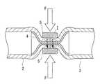
本実施形態に係る生体組織接合装置1は、生体組織接合装置(以下、生体組織接合装置1とも言う。)であって、図1に示されるように、生体組織として、例えば、図6〜図11に示されるように、管状の生体組織である腸管2,3を吻合するための装置であって、後述する筒状の吻合用部材4を介在させて突き合わせ状態に配置された一対の腸管2,3の接合端部2a,3aに跨るように腸管2,3を半径方向外方から挟み込む一対の電極5を備える装置本体6と、該装置本体6が接続される制御ユニット7と、該制御ユニット7に接続されたスイッチ8とを備えている。A biological
A biological
装置本体6は、先端に備えた電極5を、開腹部から体内に挿入するための細長いロッド9と、該ロッド9の基端側に配置され、電極5を開閉するためのハンドル10とを備えている。
電極5は、ロッド9の先端にロッド9の長手軸に直交する軸線回りに、相互に反対方向に揺動可能に取り付けられ、ロッド9の基端側に設けられたハンドル10に図示しないリンク機構により連結されている。したがって、ロッド9の基端側においてハンドル10を図1に実線および鎖線で示される範囲で操作することにより、ロッド9の先端側に設けられた電極5を開閉動作させることができるようになっている。The apparatus
The
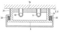
一対の電極5の対向面(密着面)5a、すなわち、接合されるべき腸管2,3の外面に密着させられる面には、図2に示されるように、後述するコラーゲン(接着材)およびエラスチン(接着材)をそれぞれ吐出する複数の吐出口11,12が開口している。コラーゲンを吐出する吐出口11とエラスチンを吐出する吐出口12とは交互に配置されていて、コラーゲンおよびエラスチンを電極5の対向面5aから均一な分布で吐出させることができるようになっている。 As shown in FIG. 2, collagen (adhesive material) and elastin, which will be described later, are provided on the opposing surfaces (contact surfaces) 5a of the pair of
また、ロッド9の基端側には、図1に示されるように、コラーゲンおよびエラスチンをそれぞれ収容するシリンジ状のタンク13が備えられ、モータ14により駆動されるようになっている(図1には一方のタンク13のみが示されている。)。タンク13と前記電極5の吐出口11,12とは、ロッド9内に配置されたチューブ15によって接続され、タンク13から押し出されたコラーゲンおよびエラスチンはチューブ15を介して電極5の吐出口11,12からそれぞれ吐出させられるようになっている。 Further, as shown in FIG. 1, syringe-
前記制御ユニット7は、図3に示されるように、接合すべき生体組織の種類に応じて、吐出するコラーゲンおよびエラスチンの吐出量を設定する吐出量設定部16と、該吐出量設定部16により設定された吐出量に応じた吐出指令信号をモータ14に対して出力する吐出指令部17と、接合に先立って電極5間に微弱電圧を加え、流れる電流を検出することにより、接合すべき生体組織の抵抗値を測定する抵抗値測定部18と、該抵抗値測定部18により測定された抵抗値に応じて、生体組織内に含有されているコラーゲンおよびエラスチンを溶融させる電圧値を算出する電圧値算出部19と、該電圧値算出部19により算出された電圧を電極5間に加える電圧印加部20と、これらを制御する制御部31とを備えている。 As shown in FIG. 3, the
前記スイッチ8は、例えば、フットスイッチであって、電極5によって生体組織が挟まれて接合の準備が整った状態で押下されることにより、前記制御ユニット7に備えられた制御部31にトリガ入力を付与するようになっている。制御部31は、スイッチ8からのトリガが入力されると、上述した抵抗値検出、電圧値算出、コラーゲンおよびエラスチンの吐出および電圧の印加の各作業を順次行わせるようになっている。 The
前記吻合用部材4は、図4に示されるように、筒状部材であって、ポリアニリン、ポリピロール、ポリチオフェンを複合し、あるいはカーボン粒子をドーピングしたポリ乳酸系ポリマーにより構成されている。
吻合用部材4は、ポリ乳酸系ポリマーにより構成されることによって、図5(a),(b)に示されるように、外力Fにより半径方向に潰されて、その内部開口を閉塞し内面を密着させても破断しない柔軟性を有している。また、吻合用部材4は、ポリ乳酸系ポリマーにより構成されることにより、コラーゲンの融点より高い温度に加熱されても変性しない耐熱性を有している。As shown in FIG. 4, the
As shown in FIGS. 5A and 5B, the
また、吻合用部材4は、ポリ乳酸系ポリマーにより構成されることにより、外力Fにより潰れた状態でコラーゲンの融点より高い温度に加熱された後に外力Fを解放すると、閉塞していた内部開口を開通させるように復元することができる弾性を有している。
さらに、吻合用部材4は、ポリアニリン、ポリピロール、ポリチオフェンを複合し、あるいはカーボン粒子をドーピングすることにより、導電性を有している。本実施形態においては、例えば、吻合しようとする生体組織よりも十分に低い抵抗値となるように十分に高い導電性を有している。In addition, the
Further, the
このように構成された本実施形態に係る生体組織接合装置1の作用について、以下に説明する。
本実施形態に係る生体組織接合装置1を用いて、生体組織として、例えば、管状の生体組織である腸管2,3を吻合する場合について説明する。
まず、制御ユニット7の吐出量設定部16により、生体組織毎に予め定められているコラーゲンおよびエラスチンの供給量を設定する。供給量の設定は、生体組織を選択させることによって行ってもよいし、コラーゲンおよびエラスチンの供給量を直接入力させることにしてもよい。The operation of the biological
A case will be described in which, for example, an
First, the supply amount of collagen and elastin, which is predetermined for each living tissue, is set by the discharge
次に、図6に示されるように、吻合すべき一対の腸管2,3の接合端部2a,3aの開口に、本実施形態に係る吻合用部材4を挿入し、図7に示されるように、一対の腸管2,3の接合端部2a,3aを突き合わせた状態とする。この状態で、図7に示されるように、接合端部2a,3a近傍の半径方向外方に、本実施形態に係る生体組織接合装置1の装置本体6の先端に配置された一対の電極5を近接させ、ハンドル10を操作することによって、図8に示されるように外力Fで腸管2,3および吻合用部材4を半径方向に挟み込む。 Next, as shown in FIG. 6, the
吻合用部材4は、柔軟性を有しているので、図8に示されるように、外力Fによってその内部開口が閉塞され内面が密着するまで潰れることができる。この状態で、制御ユニット7に接続されているフットスイッチ8を押下することにより、制御部31の作動によって、最初に抵抗値測定部18が作動させられて、電極5間に挟まれた腸管2,3の抵抗値が測定され、電圧値算出部19の作動により、印加される電圧の値が算出される。そして、制御部31は電圧印加部20を作動させて、電圧値算出部19により算出された電圧を電極5間に加える。 Since the
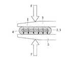
吻合用部材4は導電性を有しているので、図9に示されるように、電極5間には、腸管2,3および吻合用部材4を貫通して電流Iが流れ、腸管2,3の抵抗値の大きさと電流Iの大きさの2乗との積に比例した発熱量で発熱するようになる。 Since the
この場合において、本実施形態に係る吻合用部材4は、腸管2,3の抵抗値よりも十分に小さい抵抗値となるように高い導電性を有しているので、通電により吻合用部材4において発生する熱量は小さく、エネルギが無駄に浪費されることがない。また、吻合用部材4は、コラーゲンの溶融温度より高い耐熱性を有しているので、コラーゲンが溶融する温度まで加熱させられても変性せずにその性質を維持することができる。 In this case, the
そして、腸管2,3における発熱により、コラーゲンの溶融温度より若干高い温度となるように、電圧値算出部19により電極5間に加える電圧を調節しておくことにより、腸管2,3内に含有されている細胞外基質であるコラーゲンおよびエラスチンを溶融させて流動し易くすることができる。そして、発熱により流動するコラーゲンは、腸管2,3と吻合用部材4との隙間に浸透するようになる。この現象は、図10に示されるように、吻合用部材4の全周にわたって発生するので、流動するコラーゲンが吻合用部材4の外周面全周に浸透する。 Then, by adjusting the voltage applied between the
この場合において、本実施形態に係る生体組織接合装置1によれば、電極5間への電圧の印加に先立って、吐出指令部17からモータ14に吐出指令信号が出力され、生体組織の種類に応じた吐出量で、コラーゲンおよびエラスチンが生体組織に向けて吐出される。したがって、生体組織内に含有されるコラーゲンおよびエラスチンが少ない場合においても、接合に必要十分なコラーゲンを補充し、あるいは、エラスチンが流出することによる生体組織の硬化を抑制することができる。
その結果、コラーゲンの供給により、安定した接合力を発生することができ、接合後の生体組織における柔軟性を維持することができるという利点がある。In this case, according to the biological
As a result, there is an advantage that a stable joining force can be generated by supplying collagen, and flexibility in living tissues after joining can be maintained.
この状態から、電極5に加えていた電圧を停止し、図11に示されるように、電極5に加えていた外力Fを解除する。吻合用部材4は弾性を有しているので、外力Fが解除されると、半径方向外方に広がるように復元し、閉塞されていた内部開口が開通する。 From this state, the voltage applied to the
すなわち、吻合用部材4の外周面においては、腸管2,3と吻合用部材4との間には、コラーゲンが浸透しているので、それが接着剤となって腸管2,3と吻合用部材4とが接着されている。一方、吻合用部材4の内面においては、接着剤となるコラーゲンは存在していないので、密着していた内面どうしは接着されず、外力Fが解除されると吻合用部材4の弾性によって離間し、開口するようになる。 That is, on the outer peripheral surface of the
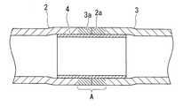
これにより、図12に示されるように、電極5により挟まれていた、腸管2,3の接合端部近傍の領域Aと、その半径方向内方に配置されている吻合用部材4とが全周にわたって接着された状態で、一対の腸管2,3の接合端部2a,3aが突き合わせ状態に接合され、一体化させられる。
すなわち、本実施形態に係る生体組織接合装置1によれば、一対の電極5によって所定の外力Fにより挟みつつ電圧を加えるだけで、一対の管状の生体組織である腸管2,3を、一度に簡単に吻合することができる。As a result, as shown in FIG. 12, the region A in the vicinity of the junction end portion of the
That is, according to the biological
その結果、縫合による従来の吻合や、周方向に複数回にわたって超音波を加えることによる吻合と比較して、その作業を大幅に簡易化することができるという利点がある。特に、エネルギ治療器を取り回すための空間の少ない内視鏡的手術において、腸管2,3を半径方向に1回挟むだけのスペースを確保すれば足りるので、その吻合作業の繁雑さを大幅に低減することができるという利点がある。 As a result, there is an advantage that the operation can be greatly simplified as compared with the conventional anastomosis by suturing and the anastomosis by applying ultrasonic waves multiple times in the circumferential direction. In particular, in an endoscopic operation with little space for handling the energy treatment device, it is sufficient to secure a space for pinching the
また、本実施形態に係る生体組織接合装置1によれば、電極5の対向面5aに設けた吐出口11,12からコラーゲンおよびエラスチンを吐出させるので、接合に必要な領域を電極5により挟んだ状態で必要な領域のみにコラーゲンおよびエラスチンを供給することができる。すなわち、事前に接合領域に塗布したり噴霧したりする方法とは異なり、コラーゲンやエラスチンが周囲の組織に垂れたり付着したりする不都合の発生を防止することができる。 Moreover, according to the biological
また、吻合用部材4によれば、腸管2,3の内壁にコラーゲンによって接着されるので、摩擦のみによって固定していた従来の吻合用部材と比較して、その吻合状態を安定して維持することができるという利点がある。さらに、吻合用部材4によれば、生体分解性の高いポリ乳酸系ポリマーにより構成されているので、吻合手術後は、経時的に分解されて消滅するようになる。すなわち、吻合された領域Aが相互に接合して治癒する頃には、本実施形態に係る吻合用部材4が消滅することにより、体内に異物を残さなくて済むという利点もある。 Further, according to the
なお、本実施形態に係る生体組織処置装置1により接合する生体組織としては、腸管2,3に限定されるものではなく、他の消化管、血管あるいは尿管等の任意の管状の生体組織や皮膚等の平坦な生体組織に適用することができる。
また、本実施形態の説明においては、筒状の吻合用部材4を介在させた状態で腸管2,3を接合させることとしたが、これに代えて、吻合用部材4の形態に制限はなく、また、吻合用部材4を用いることなく接合させることとしてもよい。The biological tissue to be joined by the biological
In the description of the present embodiment, the
また、本実施形態においては、生体組織に供給するエネルギとして電極5により電気エネルギを供給することとしたが、これに代えて、超音波振動子を接触させることにより超音波振動を供給することにしてもよい。 In the present embodiment, the electrical energy is supplied from the
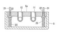
また、本実施形態においては、装置本体6の電極5には、図13〜図16に示されるように、対向面5aの外周部に、該対向面5aに設けられた吐出口11,12を取り囲むように周壁部材(漏出防止手段)21が設けられていることが好ましい。周壁部材21は、図14に示されるように、対向面5aに設けられたスリット22内に出没可能に収容されているとともに、電極5内に配置されたバネ部材(駆動手段)23によって、対向面5aから突出する方向に付勢されている。 Moreover, in this embodiment, as shown in FIGS. 13 to 16, the
これにより、図15に示されるように、電極5どうしが閉じられて、対向面5aの間に腸管2,3が挟まれるときには、腸管2,3の表面によって周壁部材21が、バネ部材23の付勢力に抗して押されてスリット22内に収容され、対向面5aを腸管2,3の表面に密着させ、電流Iを流すことができる。一方、図16に示されるように、電極5どうしが開かれて、腸管2,3の表面から離れる方向に移動させられる際には、周壁部材21がバネ部材23の付勢力によって対向面5aのスリット22内から突出させられて、腸管2,3の表面への接触状態が維持されるようになっている。 As a result, as shown in FIG. 15, when the
すなわち、電極5の対向面5aによって腸管2,3が挟まれた状態、および、腸管2,3の表面に対して電極5の対向面5aが若干浮いた状態のいずれにおいても、吐出口11,12の外側を取り囲む周壁部材21が腸管2,3の表面に密着させられているので、吐出口11,12から吐出されるコラーゲンやエラスチンのような接着材Bが、周壁部材21から外側に漏出することが防止される。 That is, in both the state in which the
これにより、硬化していない接着材Bが接合部位の外側において周辺の組織を接着してしまう不都合の発生を防止することができる。
また、周壁部材21は、対向面5aに対して出没可能に設けられて、バネ部材23によって突出する方向に付勢されているので、電極5の対向面5aどうしを密着させて通電する際には、対向面5a内に引っ込んで、対向面5aどうしの密着を阻害しない。さらに、電極5に加えていた外力Fが緩んで、対向面5aどうしの間隔が開く場合においては、バネ部材23によって周壁部材21が対向面5aから突出させられて、腸管2,3への密着状態が維持され、接着材Bが外側に漏れ出るのを防止し続けることができる。Thereby, the generation | occurrence | production of the problem that the adhesive material B which has not hardened adhere | attaches a surrounding structure | tissue in the outer side of a junction part can be prevented.
Moreover, since the surrounding
また、上記においては、電極5の対向面5aにスリット22を設けることにより、該スリット22内に収容した周壁部材21を出没させることとしたが、これに代えて、図17および図18に示されるように、周壁部材21として、電極5全体を覆う箱状のものを採用してもよい。この場合においても、図17に示されるように、バネ部材23によって周壁部材21の端部を電極5の対向面5aに対して突出する方向に付勢することにより、電極5が密着状態(通電時)および若干開いた状態(非通電時)のいずれにおいても、周壁部材21を腸管2,3の表面に密着させて、吐出口11,12から吐出される接着材Bが周壁部材21から外側に漏出することを防止することができる。 In the above description, the
また、周壁部材21によってコラーゲンやエラスチンの漏出を防止する漏出防止手段に代えて、図19,図20に示されるように、対向面5aに開口する吸引口24と、該吸引口24を負圧に吸引する吸引ポンプ(負圧供給手段)25とを設けることにしてもよい。この場合に、吸引口24は、図20に示されるように、吐出口11,12の外側を取り囲む位置に配置されていることが好ましい。このようにすることで、吐出口11,12から吐出されるコラーゲンやエラスチンが多すぎる場合であっても、吸引ポンプ25を作動させて吸引口24を負圧に吸引し、余剰のコラーゲンやエラスチンを排除することができる。これにより、対向面5a間からコラーゲンやエラスチンが漏出することを防止できる。 Further, in place of the leakage prevention means for preventing leakage of collagen and elastin by the
吸引口24としては対向面5aに開口するものの他、図21に示されるように、対向面5aに隣接する側面に5b設けられていてもよい。このようにすることで、吸引ポンプ25を作動させて吸引口24を負圧に吸引することにより、対向面5aの隙間から外部に流れようとするコラーゲンやエラスチンを吸引口24から吸引してそれ以上の漏出を防止することができる。 The
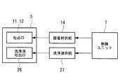
また、図22に示されるように、図19〜図21に示される吸引口24に代えて、洗浄液吐出口26、吸引ポンプ25に代えて洗浄液ポンプ27を採用してもよい。洗浄液としては、例えば、生理食塩水、乳酸リンゲル液あるいはリン酸緩衝生理食塩水を採用することができる。このようにすることで、洗浄液ポンプ27の作動により洗浄液吐出口26から洗浄液を吐出して、余分なコラーゲンやエラスチンを洗浄することができる。すなわち、コラーゲンやエラスチンの濃度を希釈することで接着力を低下させて、漏出しても他の組織に接着しないようにすることができる。また、この場合には、洗浄液吐出口26の周囲を取り囲む位置に、洗浄液吸引口(図示略)を設けて、余剰の洗浄液を吸引排除することにしてもよい。 Further, as shown in FIG. 22, a cleaning
また、上記各実施形態においては、吐出口11,12からコラーゲンおよびエラスチンを吐出することとしたが、これに代えて、他の接着材を吐出することにしてもよい。接着材としては一液性のものでもよいし、二液性のものでもよい。化学反応により硬化するものでもよいし、熱、光あるいは超音波のような物理的な刺激によって硬化する性質のものでもよい。 Further, in each of the above embodiments, collagen and elastin are discharged from the
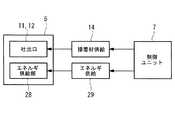
物理的刺激によって硬化する接着材を用いる場合には、漏出防止手段として、図23に示されるように、電極5にエネルギ供給部28を設け、該エネルギ供給部28に対してエネルギを供給するエネルギ供給手段29を接続することにしてもよい。
すなわち、熱を加えることによって硬化する接着材を吐出する場合には、図24および図25に示されるように、対向面5aにヒータ28aを設け、吐出された接着材を加熱することにすればよい。図24は、対向面5aの外周部分にヒータ28aを設けた例、図25は対向面5aに設けられた全ての吐出口11,12の間にヒータ28aを設けた例をそれぞれ示している。In the case of using an adhesive that is cured by physical stimulation, as shown in FIG. 23, an
That is, when discharging an adhesive that is cured by applying heat, as shown in FIGS. 24 and 25, a
また、光を照射することにより硬化する接着材を吐出する場合には、図26,図27に示されるように、対向面5aに光を照射する投光部28bを設け、吐出された接着材に対して光を照射することにすればよい。投光部28bは光を発生する光源であってもよいし、光を導いてくる光ファイバのような導光部材の端部であってもよい。図26は対向面5aの吐出口11,12の間に投光部28bを設けた例、図27は電極5の対向面5aに隣接する側面5bに投光部28bを設けた例をそれぞれ示している。
また、超音波を照射することにより硬化する接着材を吐出する場合には、図28に示されるように、対向面5aに超音波振動子28cを設けることにすればよい。In the case of discharging an adhesive that is cured by irradiating light, as shown in FIGS. 26 and 27, a
In the case of discharging an adhesive that is cured by irradiating ultrasonic waves, an
また、図29および図30に示されるように、電極5の対向面5aに腸管2,3に対して吐出された接着材Bの硬度を検出する硬度センサ30を配置することにしてもよい。硬度センサ30としては、図29に示されるように、塗布された接着材Bの表面を押圧してそのときの荷重を測定する荷重センサ30であってもよい。また、図30に示されるように、塗布された接着材Bの表面にレーザ光Cを照射する光源30aと、接着材Bの表面において反射して戻るレーザ光Cを検出する受光部30bと備え、レーザドップラ方式によって接着材Bの硬度を検出するものであってもよい。 Further, as shown in FIGS. 29 and 30, a
そして、硬度センサ30によって検出された硬度情報を図示しない表示部(報知手段)によって表示することにより、電極5を取り外すか否かを判断したり、あるいは、上述したように接着材Bを硬化させる漏出防止手段28,29を備えている場合には、漏出防止手段28,29の作動を調節したりすることにすればよい。 Then, by displaying the hardness information detected by the
また、本実施形態においては、把持手段として、接合すべき生体組織を挟んで加圧するとともに生体組織にエネルギを供給して生体組織内のコラーゲンを溶融させるエネルギ供給手段としての電極5を例示したが、これに代えて、エネルギを供給することなく、生体組織を挟んで把持する把持手段を採用してもよい。この場合に、吐出口11,12からは2液タイプの接着材を別々に吐出させることにすればよい。 Moreover, in this embodiment, although the
このようにすることで、周壁部材21等の漏洩防止手段によって生体組織表面と密着面5aとの隙間から接着材が漏洩することが防止され、目的部位以外の部位において他の組織を接着してしまうことを防止できる。
したがって、フィブリノーゲンおよびトロンビンという2種類の血液凝固成分からなるフィブリン系接着材だけでなく、接着成分がゼラチン、架橋成分がホルムアルデヒドであるアルデヒド系接着材や、接着成分がアルブミン、架橋成分がグルタルアルデヒドであるアルデヒド系接着剤等、接着強度がより高い接着材を使用することも可能となる。By doing so, leakage prevention means such as the
Therefore, not only fibrin-based adhesives consisting of two types of blood coagulation components, fibrinogen and thrombin, but also aldehyde-based adhesives whose adhesive component is gelatin and whose cross-linking component is formaldehyde, and whose adhesive component is albumin and whose cross-linking component is glutaraldehyde. It is also possible to use an adhesive having a higher adhesive strength such as a certain aldehyde adhesive.
B 接着材(コラーゲン、エラスチン)
1 生体組織処置装置(生体組織接合装置)
2,3 腸管(生体組織)
5 電極(把持手段、エネルギ供給手段)
5a 対向面(密着面)
5b 側面
11,12 吐出口
13 タンク(接着材供給手段)
16 吐出量設定部(コラーゲン供給量制御部、エラスチン供給量制御部)
21 周壁部材(漏出防止手段)
23 バネ部材(駆動手段)
24 吸引口、洗浄液吸引口(漏出防止手段)
25 吸引ポンプ(負圧供給手段)
26 洗浄液吐出口(漏出防止手段)
27 洗浄液ポンプ(洗浄液供給手段)
28 エネルギ供給部(刺激手段)
28a ヒータ(刺激手段)
28b 投光部(刺激手段)
28c 超音波振動子(刺激手段)
30 硬度センサ(硬度検出手段)B Adhesive (collagen, elastin)
1 Biological tissue treatment device (biological tissue bonding device)
2, 3 Intestinal tract (living tissue)
5 Electrodes (gripping means, energy supply means)
5a Opposite surface (contact surface)
16 Discharge amount setting unit (collagen supply amount control unit, elastin supply amount control unit)
21 Perimeter wall member (leakage prevention means)
23 Spring member (drive means)
24 Suction port, cleaning fluid suction port (leakage prevention means)
25 Suction pump (negative pressure supply means)
26 Cleaning liquid outlet (leakage prevention means)
27 Cleaning liquid pump (cleaning liquid supply means)
28 Energy supply unit (stimulation means)
28a Heater (stimulation means)
28b Light emitting part (stimulation means)
28c Ultrasonic transducer (stimulation means)
30 Hardness sensor (hardness detection means)
Claims (7)
Translated fromJapanese該接着材供給手段が、前記把持手段の前記生体組織への密着面に接着材を吐出する吐出口と、該吐出口からの接着材の吐出時に前記生体組織の表面と前記密着面との隙間から接着力を有する接着材の漏出を防止する漏出防止手段を有し、
該漏出防止手段が、前記密着面の外周を取り囲み、該密着面と前記生体組織の表面との隙間から漏れてくる接着材を堰き止める周壁部材を有し、
該周壁部材が、前記密着面に対して出没可能に設けられ、該周壁部材を突出させる駆動手段を備える生体組織処置装置。A gripping means for sandwiching the living tissue to be joined, and an adhesive supply means for supplying an adhesive to the living tissue gripped by the gripping means,
The adhesive material supply means discharges the adhesive material to the contact surface of the grasping means to the living tissue, and a gap between the surface of the living tissue and the contact surface when the adhesive material is discharged from the discharge port. Having leakage prevention means for preventing leakage of adhesive having adhesive force from,
The leakage preventing means has a peripheral wall member that surrounds the outer periphery of the contact surface and dams up an adhesive that leaks from a gap between the contact surface and the surface of the living tissue,
A living tissue treatment apparatus comprising:a driving unit that is providedso that the peripheral wall member can protrude and retract with respect to the contact surface, and causes the peripheral wall member to protrude .
該接着材供給手段が、前記把持手段の前記生体組織への密着面に接着材を吐出する吐出口と、該吐出口からの接着材の吐出時に前記生体組織の表面と前記密着面との隙間から接着力を有する接着材の漏出を防止する漏出防止手段を有し、
該漏出防止手段が、前記密着面近傍に設けられ、洗浄液を吐出する洗浄液吐出口と、該洗浄液吐出口に洗浄液を供給する洗浄液供給手段とを備える生体組織処置装置。A gripping means for sandwiching the living tissue to be joined, and an adhesive supply means for supplying an adhesive to the living tissue gripped by the gripping means,
The adhesive material supply means discharges the adhesive material to the contact surface of the grasping means to the living tissue, and a gap between the surface of the living tissue and the contact surface when the adhesive material is discharged from the discharge port. Having leakage prevention means for preventing leakage of adhesive having adhesive force from,
該漏out preventing means is provided in vicinity of the contact surface, and the cleaning liquid discharge port for discharging the cleaning liquid, BIOLOGICAL tissue treatment deviceand a cleaning liquid supply means for supplying a cleaning liquid to the cleaning liquid discharge port.
該接着材供給手段が、前記把持手段の前記生体組織への密着面に接着材を吐出する吐出口と、該吐出口からの接着材の吐出時に前記生体組織の表面と前記密着面との隙間から接着力を有する接着材の漏出を防止する漏出防止手段を備え、
前記接着材が、物理的刺激により硬化する接着材であり、
前記漏出防止手段が、前記生体組織に吐出された接着材に物理的刺激を付与する刺激手段を備える生体組織処置装置。A gripping means for sandwiching the living tissue to be joined, and an adhesive supply means for supplying an adhesive to the living tissue gripped by the gripping means,
The adhesive material supply means discharges the adhesive material to the contact surface of the grasping means to the living tissue, and a gap between the surface of the living tissue and the contact surface when the adhesive material is discharged from the discharge port. Provided with leakage preventing means for preventing leakage of adhesive having adhesive strength from
The adhesive is an adhesive that cures by physical stimulation,
It said leakage preventing means, living body tissue treatment devicecomprising a stimulation means for applying a physical stimulation to the adhesive discharged into the biological tissue.
該接着材供給手段が、前記把持手段の前記生体組織への密着面に接着材を吐出する吐出口と、該吐出口からの接着材の吐出時に前記生体組織の表面と前記密着面との隙間から接着力を有する接着材の漏出を防止する漏出防止手段を備え、
該漏洩防止手段が、前記生体組織に塗布された接着材の硬度を検出する硬度検出手段と、該硬度検出手段により検出された硬度が所定の閾値に満たないことを報知する報知手段とを備える生体組織処置装置。A gripping means for sandwiching the living tissue to be joined, and an adhesive supply means for supplying an adhesive to the living tissue gripped by the gripping means,
The adhesive material supply means discharges the adhesive material to the contact surface of the grasping means to the living tissue, and a gap between the surface of the living tissue and the contact surface when the adhesive material is discharged from the discharge port. Provided with leakage preventing means for preventing leakage of adhesive having adhesive strength from
The leakage prevention means includes hardness detection means for detecting the hardness of the adhesive applied to the living tissue, and notification means for notifying that the hardness detected by the hardness detection means is less than a predetermined threshold. raw body tissue treatment device.
Priority Applications (2)
| Application Number | Priority Date | Filing Date | Title |
|---|---|---|---|
| JP2009248163AJP5519244B2 (en) | 2009-10-28 | 2009-10-28 | Biological tissue treatment device |
| US12/638,013US8460288B2 (en) | 2009-10-28 | 2009-12-15 | Biological-tissue joining apparatus |
Applications Claiming Priority (1)
| Application Number | Priority Date | Filing Date | Title |
|---|---|---|---|
| JP2009248163AJP5519244B2 (en) | 2009-10-28 | 2009-10-28 | Biological tissue treatment device |
Publications (2)
| Publication Number | Publication Date |
|---|---|
| JP2011092347A JP2011092347A (en) | 2011-05-12 |
| JP5519244B2true JP5519244B2 (en) | 2014-06-11 |
Family
ID=44109999
Family Applications (1)
| Application Number | Title | Priority Date | Filing Date |
|---|---|---|---|
| JP2009248163AExpired - Fee RelatedJP5519244B2 (en) | 2009-10-28 | 2009-10-28 | Biological tissue treatment device |
Country Status (1)
| Country | Link |
|---|---|
| JP (1) | JP5519244B2 (en) |
Families Citing this family (4)
| Publication number | Priority date | Publication date | Assignee | Title |
|---|---|---|---|---|
| CA2896760A1 (en) | 2012-12-30 | 2014-07-03 | Omrix Biopharmaceuticals Ltd. | Device and method for the application of a curable fluid composition to a portion of a bodily organ |
| US9119606B2 (en)* | 2013-01-21 | 2015-09-01 | Ethicon, Inc. | Sealant delivery device for anastomotic stapler |
| US9826965B2 (en)* | 2014-06-10 | 2017-11-28 | Ethicon Llc | Devices for sealing a body lumen |
| WO2016063360A1 (en)* | 2014-10-21 | 2016-04-28 | オリンパス株式会社 | Medical treatment device |
Family Cites Families (6)
| Publication number | Priority date | Publication date | Assignee | Title |
|---|---|---|---|---|
| JP3756556B2 (en)* | 1995-10-06 | 2006-03-15 | オリンパス株式会社 | Grasping forceps |
| JP2003235865A (en)* | 2002-02-14 | 2003-08-26 | Olympus Optical Co Ltd | Thermal type treatment implement and treatment system using the same |
| EP2298187B1 (en)* | 2002-04-16 | 2017-06-07 | Covidien LP | Surgical stapler and method |
| US7572257B2 (en)* | 2002-06-14 | 2009-08-11 | Ncontact Surgical, Inc. | Vacuum coagulation and dissection probes |
| US8678263B2 (en)* | 2007-09-24 | 2014-03-25 | Covidien Lp | Materials delivery system for stapling device |
| US8454599B2 (en)* | 2008-08-13 | 2013-06-04 | Olympus Medical Systems Corp. | Treatment apparatus and electro-surgical device |
- 2009
- 2009-10-28JPJP2009248163Apatent/JP5519244B2/ennot_activeExpired - Fee Related
Also Published As
| Publication number | Publication date |
|---|---|
| JP2011092347A (en) | 2011-05-12 |
Similar Documents
| Publication | Publication Date | Title |
|---|---|---|
| US8460288B2 (en) | Biological-tissue joining apparatus | |
| JP6523281B2 (en) | Ultrasonic surgical instrument with electrosurgical features | |
| JP5231658B2 (en) | THERAPEUTIC TREATMENT DEVICE AND METHOD OF CONTROLLING THE TREATMENT TREATMENT DEVICE | |
| JP5231659B2 (en) | Therapeutic treatment device | |
| US5895412A (en) | Device and method for sealing tissue | |
| JP5123437B2 (en) | THERAPEUTIC TREATMENT TOOL, THERAPEUTIC TREATMENT DEVICE, AND THERAPEUTIC TREATMENT METHOD | |
| JP5519244B2 (en) | Biological tissue treatment device | |
| WO1997013461A9 (en) | Device and method for sealing tissue | |
| JP5123435B2 (en) | THERAPEUTIC TREATMENT TOOL, THERAPEUTIC TREATMENT DEVICE, AND THERAPEUTIC TREATMENT METHOD | |
| US20170156713A1 (en) | Ultrasound assisted tissue welding device | |
| JP5389996B2 (en) | THERAPEUTIC TREATMENT TOOL, THERAPEUTIC TREATMENT DEVICE, AND THERAPEUTIC TREATMENT METHOD | |
| US20240389989A1 (en) | Biopsy site tissue repair device and methods | |
| JP2008301955A (en) | Biomedical tissue joining apparatus | |
| JP2011101744A (en) | Living tissue treatment apparatus | |
| WO2024229303A2 (en) | Biopsy site tissue repair apparatus and methods | |
| JP2010057688A (en) | High frequency therapeutic apparatus | |
| JP2009125442A (en) | Biotissue joining device | |
| US10258283B2 (en) | Implant and insertion device for an implant | |
| JP2010057686A (en) | Living body tissue bonding device | |
| JP2009273559A (en) | Hemostatic device | |
| JP2010125157A (en) | Ultrasonic incision device | |
| JP2009153620A (en) | Instrument and method for joining biological tissue | |
| Sorg | Laser-assisted tissue closure with a unique solder-film patch | |
| WO2024247993A1 (en) | Surgical treatment device | |
| CN118804716A (en) | Biopsy site tissue repair device and method |
Legal Events
| Date | Code | Title | Description |
|---|---|---|---|
| A621 | Written request for application examination | Free format text:JAPANESE INTERMEDIATE CODE: A621 Effective date:20121019 | |
| A977 | Report on retrieval | Free format text:JAPANESE INTERMEDIATE CODE: A971007 Effective date:20130919 | |
| A131 | Notification of reasons for refusal | Free format text:JAPANESE INTERMEDIATE CODE: A131 Effective date:20131008 | |
| TRDD | Decision of grant or rejection written | ||
| A01 | Written decision to grant a patent or to grant a registration (utility model) | Free format text:JAPANESE INTERMEDIATE CODE: A01 Effective date:20140318 | |
| A61 | First payment of annual fees (during grant procedure) | Free format text:JAPANESE INTERMEDIATE CODE: A61 Effective date:20140403 | |
| S531 | Written request for registration of change of domicile | Free format text:JAPANESE INTERMEDIATE CODE: R313531 | |
| R350 | Written notification of registration of transfer | Free format text:JAPANESE INTERMEDIATE CODE: R350 | |
| LAPS | Cancellation because of no payment of annual fees |