JP5519211B2 - Endoscope device - Google Patents
Endoscope deviceDownload PDFInfo
- Publication number
- JP5519211B2 JP5519211B2JP2009185760AJP2009185760AJP5519211B2JP 5519211 B2JP5519211 B2JP 5519211B2JP 2009185760 AJP2009185760 AJP 2009185760AJP 2009185760 AJP2009185760 AJP 2009185760AJP 5519211 B2JP5519211 B2JP 5519211B2
- Authority
- JP
- Japan
- Prior art keywords
- unit
- endoscope apparatus
- shielding
- main body
- heat radiating
- Prior art date
- Legal status (The legal status is an assumption and is not a legal conclusion. Google has not performed a legal analysis and makes no representation as to the accuracy of the status listed.)
- Active
Links
- 238000003780insertionMethods0.000claimsdescription76
- 230000037431insertionEffects0.000claimsdescription76
- 238000005452bendingMethods0.000claimsdescription22
- 238000005286illuminationMethods0.000claimsdescription18
- 230000017525heat dissipationEffects0.000claimsdescription12
- 230000005855radiationEffects0.000claimsdescription10
- 230000008602contractionEffects0.000claimsdescription8
- 230000008859changeEffects0.000claimsdescription5
- 239000011347resinSubstances0.000claimsdescription5
- 229920005989resinPolymers0.000claimsdescription5
- 238000003384imaging methodMethods0.000description20
- 230000007246mechanismEffects0.000description14
- 238000012986modificationMethods0.000description8
- 230000004048modificationEffects0.000description8
- 238000012360testing methodMethods0.000description8
- 238000012545processingMethods0.000description6
- 230000005540biological transmissionEffects0.000description4
- 230000003287optical effectEffects0.000description4
- 239000000463materialSubstances0.000description3
- 238000000034methodMethods0.000description3
- 238000001816coolingMethods0.000description2
- 238000010586diagramMethods0.000description2
- 238000009434installationMethods0.000description2
- 239000002184metalSubstances0.000description2
- 238000007789sealingMethods0.000description2
- 125000002066L-histidyl groupChemical group[H]N1C([H])=NC(C([H])([H])[C@](C(=O)[*])([H])N([H])[H])=C1[H]0.000description1
- 238000013459approachMethods0.000description1
- 230000001174ascending effectEffects0.000description1
- 238000013461designMethods0.000description1
- 230000002093peripheral effectEffects0.000description1
- 230000008569processEffects0.000description1
- 230000000007visual effectEffects0.000description1
Images


Classifications
- A—HUMAN NECESSITIES
- A61—MEDICAL OR VETERINARY SCIENCE; HYGIENE
- A61B—DIAGNOSIS; SURGERY; IDENTIFICATION
- A61B1/00—Instruments for performing medical examinations of the interior of cavities or tubes of the body by visual or photographical inspection, e.g. endoscopes; Illuminating arrangements therefor
- A61B1/00002—Operational features of endoscopes
- A61B1/00039—Operational features of endoscopes provided with input arrangements for the user
- A61B1/00042—Operational features of endoscopes provided with input arrangements for the user for mechanical operation
- A—HUMAN NECESSITIES
- A61—MEDICAL OR VETERINARY SCIENCE; HYGIENE
- A61B—DIAGNOSIS; SURGERY; IDENTIFICATION
- A61B1/00—Instruments for performing medical examinations of the interior of cavities or tubes of the body by visual or photographical inspection, e.g. endoscopes; Illuminating arrangements therefor
- A61B1/00002—Operational features of endoscopes
- A61B1/00043—Operational features of endoscopes provided with output arrangements
- A61B1/00045—Display arrangement
- A61B1/00052—Display arrangement positioned at proximal end of the endoscope body
- A—HUMAN NECESSITIES
- A61—MEDICAL OR VETERINARY SCIENCE; HYGIENE
- A61B—DIAGNOSIS; SURGERY; IDENTIFICATION
- A61B1/00—Instruments for performing medical examinations of the interior of cavities or tubes of the body by visual or photographical inspection, e.g. endoscopes; Illuminating arrangements therefor
- A61B1/00112—Connection or coupling means
- A61B1/00121—Connectors, fasteners and adapters, e.g. on the endoscope handle
- A61B1/00128—Connectors, fasteners and adapters, e.g. on the endoscope handle mechanical, e.g. for tubes or pipes
- A—HUMAN NECESSITIES
- A61—MEDICAL OR VETERINARY SCIENCE; HYGIENE
- A61B—DIAGNOSIS; SURGERY; IDENTIFICATION
- A61B1/00—Instruments for performing medical examinations of the interior of cavities or tubes of the body by visual or photographical inspection, e.g. endoscopes; Illuminating arrangements therefor
- A61B1/005—Flexible endoscopes
- A61B1/0051—Flexible endoscopes with controlled bending of insertion part
- A61B1/0052—Constructional details of control elements, e.g. handles
- A—HUMAN NECESSITIES
- A61—MEDICAL OR VETERINARY SCIENCE; HYGIENE
- A61B—DIAGNOSIS; SURGERY; IDENTIFICATION
- A61B1/00—Instruments for performing medical examinations of the interior of cavities or tubes of the body by visual or photographical inspection, e.g. endoscopes; Illuminating arrangements therefor
- A61B1/06—Instruments for performing medical examinations of the interior of cavities or tubes of the body by visual or photographical inspection, e.g. endoscopes; Illuminating arrangements therefor with illuminating arrangements
- A61B1/0661—Endoscope light sources
- A61B1/0669—Endoscope light sources at proximal end of an endoscope
- A—HUMAN NECESSITIES
- A61—MEDICAL OR VETERINARY SCIENCE; HYGIENE
- A61B—DIAGNOSIS; SURGERY; IDENTIFICATION
- A61B1/00—Instruments for performing medical examinations of the interior of cavities or tubes of the body by visual or photographical inspection, e.g. endoscopes; Illuminating arrangements therefor
- A61B1/12—Instruments for performing medical examinations of the interior of cavities or tubes of the body by visual or photographical inspection, e.g. endoscopes; Illuminating arrangements therefor with cooling or rinsing arrangements
- A61B1/128—Instruments for performing medical examinations of the interior of cavities or tubes of the body by visual or photographical inspection, e.g. endoscopes; Illuminating arrangements therefor with cooling or rinsing arrangements provided with means for regulating temperature
- G—PHYSICS
- G02—OPTICS
- G02B—OPTICAL ELEMENTS, SYSTEMS OR APPARATUS
- G02B23/00—Telescopes, e.g. binoculars; Periscopes; Instruments for viewing the inside of hollow bodies; Viewfinders; Optical aiming or sighting devices
- G02B23/24—Instruments or systems for viewing the inside of hollow bodies, e.g. fibrescopes
- G02B23/2476—Non-optical details, e.g. housings, mountings, supports
Landscapes
- Health & Medical Sciences (AREA)
- Life Sciences & Earth Sciences (AREA)
- Surgery (AREA)
- Physics & Mathematics (AREA)
- Engineering & Computer Science (AREA)
- Optics & Photonics (AREA)
- Biophysics (AREA)
- General Health & Medical Sciences (AREA)
- Pathology (AREA)
- Radiology & Medical Imaging (AREA)
- Veterinary Medicine (AREA)
- Biomedical Technology (AREA)
- Heart & Thoracic Surgery (AREA)
- Medical Informatics (AREA)
- Molecular Biology (AREA)
- Animal Behavior & Ethology (AREA)
- Nuclear Medicine, Radiotherapy & Molecular Imaging (AREA)
- Public Health (AREA)
- Mechanical Engineering (AREA)
- Astronomy & Astrophysics (AREA)
- General Physics & Mathematics (AREA)
- Endoscopes (AREA)
Description
Translated fromJapanese本発明は、被検物の内部を観察するための内視鏡装置に関する。 The present invention relates to an endoscope apparatus for observing the inside of a test object.
各種被検物の内部を観察する目的で、可撓性を有し長尺な挿入部を備えた内視鏡装置が広く使用されている(例えば、特許文献1参照)。このような内視鏡装置では、挿入部の先端にCCD等からなる撮像装置が設けられ、当該撮像装置が取得した画像が挿入部を通って本体に送信され、画像処理等を経てディスプレイ等の表示部に表示される。 For the purpose of observing the inside of various specimens, an endoscope apparatus having a flexible and long insertion portion is widely used (for example, see Patent Document 1). In such an endoscope apparatus, an imaging device made up of a CCD or the like is provided at the distal end of the insertion unit, and an image acquired by the imaging device is transmitted to the main body through the insertion unit, and is subjected to image processing or the like. Displayed on the display.
被検物の内部には光が届かないことが多いため、通常内視鏡装置においては、発光ダイオード(LED)等の発光部材を含む照明機構を用いて撮像装置の視野を明るくする(照明する)ことが行われる。照明機構による照明方式としては、発光部材が撮像装置同様挿入部の先端部に配置されて直接撮像装置の視野を照明する方式や、発光部材が本体に配置されて、発光部材と接続されたライトガイドにより照明光を挿入部先端まで導いて撮像装置の視野を照明する方式等が知られている。 Since light often does not reach the inside of a test object, in an ordinary endoscope apparatus, the field of view of the imaging apparatus is brightened (illuminated) using an illumination mechanism including a light emitting member such as a light emitting diode (LED). ) Is done. As the illumination method by the illumination mechanism, a light emitting member is arranged at the distal end portion of the insertion portion like the imaging device to directly illuminate the field of view of the imaging device, or a light in which the light emitting member is arranged in the main body and connected to the light emitting member A method of illuminating the field of view of an imaging device by guiding illumination light to the distal end of an insertion portion with a guide is known.
近年、内視鏡装置をより使いやすくするために、挿入部の操作を行う操作部と、上述の表示部とが一体となり、かつ片手で持てる程度に小型化されたものが提案されている(例えば、特許文献2参照。)。このような内視鏡装置においては、操作部、表示部、及び本体が一つの筐体にまとめられ、ユーザが当該筐体を直接把持して内視鏡を使用する。 In recent years, in order to make the endoscope apparatus easier to use, an operation unit for operating an insertion unit and the above-described display unit are integrated and have been reduced in size so as to be held with one hand ( For example, see Patent Document 2.) In such an endoscope apparatus, the operation unit, the display unit, and the main body are combined into one casing, and the user directly grips the casing and uses the endoscope.
ところで、特許文献2に記載のように小型化した筐体を使用する内視鏡装置で、ライトガイドを用いた照明機構を採用する場合、発光部材は本体を兼ねる筐体の内部に配置されることになる。内視鏡装置の使用時においては発光部材が高温となるので、本体に収容された他の機構への影響を防ぐため、金属等からなるフィン等を有するヒートシンク等を筐体の外部に設け、発光部材の発する熱を筐体の外部に逃がすことが行われる。 By the way, when adopting an illumination mechanism using a light guide in an endoscope apparatus using a miniaturized casing as described in Patent Document 2, the light emitting member is arranged inside the casing that also serves as the main body. It will be. Since the light emitting member becomes high temperature when using the endoscope apparatus, in order to prevent the influence on other mechanisms accommodated in the main body, a heat sink having fins made of metal or the like is provided outside the housing, The heat generated by the light emitting member is released to the outside of the housing.
このとき、ヒートシンク等の放熱機構も発光部材に準じて比較的高温となるが、放熱機構は筐体の外部に露出しているので、当該内視鏡装置における使用者の取り扱いが困難となるという問題がある。 At this time, the heat dissipation mechanism such as a heat sink also has a relatively high temperature according to the light emitting member. However, since the heat dissipation mechanism is exposed to the outside of the housing, it is difficult for the user to handle the endoscope apparatus. There's a problem.
本発明は、上述したような事情に鑑みてなされたものであって、把持可能な本体を有しながら、取り扱いの容易な内視鏡装置を提供することを目的とする。 The present invention has been made in view of the above-described circumstances, and an object thereof is to provide an endoscope apparatus that is easy to handle while having a grippable main body.
本発明の内視鏡装置は、可撓性を有して長尺に形成され、湾曲操作可能な湾曲部を有する挿入部と、前記挿入部の先端に設けられた観察手段と、前記挿入部の先端に設けられ、前記観察手段の視野を照明する照明部と、前記挿入部に接続され、前記観察手段の取得した画像を表示する表示部と、前記湾曲部を操作するための操作部と、把持した状態で前記操作部を操作可能な把持部と、を有し、片手で把持及び操作可能な大きさに形成された本体部と、前記本体部に設けられ、照明光の光源となる発光部材と、前記照明部と前記発光部材とを接続するライトガイドとを有する光源部と、少なくとも一部が前記本体部から突出して露出するように前記本体部に設けられ、前記発光部材と熱的に接続された放熱部と、前記本体部から突出して設けられ、前記放熱部の周囲の少なくとも一部を覆い、前記放熱部の外部との接触を抑制する樹脂製の遮蔽部と、を備え、前記遮蔽部の先端は、前記放熱部の先端よりもさらに先端側に位置していることを特徴とする。An endoscope apparatus according to the present invention includes an insertion portion having a bending portion that is flexible and can be bent, observation means provided at a distal end of the insertion portion, and the insertion portion. An illumination unit that illuminates the visual field of the observation unit, a display unit that is connected to the insertion unit and displays an image acquired by the observation unit, and an operation unit for operating the bending unit A main body formed in a size that can be gripped and operated with one hand, and provided in the main body, and serves as a light source of illumination light A light source having a light emitting member, a light guide connecting the illuminating unit and the light emitting member, and at least a part of the light sourceprojecting from the main body to be exposed; to the connected heat radiating portion,protrudes from the body portion It is, covers at least a portion of the periphery of the heat radiating portion, and aresin shielding portion suppresses contact with the outside of the heat radiatingportion, the distal end of the shield portion further than the tip of the heat radiating portion It characterized that youhave located distally.
前記遮蔽部は、可撓性を有する帯状の部材を含んで構成されてもよい。 The shielding part may include a belt-like member having flexibility.
また、前記遮蔽部は、その形状を変化させて、前記放熱部の周囲の少なくとも一部を覆った状態と、前記放熱部を覆わない状態とに切り替え可能であってもよい。
この場合、前記遮蔽部は、複数の筒状部材が軸線方向に相対移動可能に連結されたテレスコピック構造を有してもよいし、板状部材が回動可能に連結された複数の伸縮部を有してもよい。The shielding part may be changeable in shape so as to be switched between a state in which at least a part of the periphery of the heat radiating part is covered and a state in which the heat radiating part is not covered.
In this case, the shielding part may have a telescopic structure in which a plurality of cylindrical members are connected so as to be relatively movable in the axial direction, or a plurality of extendable parts in which plate-like members are rotatably connected. You may have.
また、前記遮蔽部は、前記放熱部の周囲の空気の流通を促進する貫通孔を有してもよい。 Moreover, the said shielding part may have a through-hole which promotes the circulation | circulation of the air around the said thermal radiation part.
本発明の内視鏡装置によれば、把持可能な本体を有しながら、取り扱いの容易な内視鏡装置とすることができる。 According to the endoscope apparatus of the present invention, it is possible to provide an endoscope apparatus that is easy to handle while having a grippable main body.
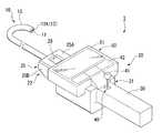
本発明の第1実施形態について、図1から図6(b)を参照して説明する。図1は、本実施形態の内視鏡装置1を示す全体斜視図である。
内視鏡装置1は、可撓性を有する長尺の挿入部10と、挿入部10の基端側に接続された本体部20とを備えている。A first embodiment of the present invention will be described with reference to FIGS. 1 to 6B. FIG. 1 is an overall perspective view showing an
The
挿入部10は、被検物内に挿入される部分であり、可撓性を有する管状の部材で長尺に形成されている。挿入部10は、先端に設けられた撮像部(観察手段)11及び照明部12と、挿入部10の先端の向きを所望の方向に変化させるための湾曲部13とを備えている。 The
撮像部11は、被検物内部における観察部位の反射光を結像させる図示しない対物光学系、及び当該対物光学系が結像した当該観察部位の反射光を光電変換するCCD等の撮像素子を備えた公知の構成を有する。撮像部11には撮像素子の取得した映像信号を送信するための図示しない信号線が接続されており、挿入部10内を通って本体部20まで延びている。必要に応じて、撮像部11の視野角、視野方向、観察深度などを調節するための公知の光学アダプタが撮像部11に取り付けられてもよい。 The
照明部12は、光学素子等を含んで構成され、挿入部10の先端に照明光の射出面12Aを有し、照明光によって撮像部11の視野を照明する。照明光の光源である発光部材は、本体部20の内部に配置されているが、これについては後述する。 The
湾曲部13は、筒状の節輪又は湾曲コマ(以下、「節輪等」と称する。)が軸線方向に整列されて連結された公知の構成を有し、挿入部10の軸線から離間する所定の方向に湾曲操作可能である。湾曲部13を湾曲させるためのワイヤ等の伝達部材(後述)は各節輪等を挿通されて先端側の節輪等に接続されている。本実施形態の内視鏡装置1において、湾曲部13は、挿入部10の軸線から離間する4方向に湾曲可能であり、各方向に対応した4本の伝達部材が挿入部10内を通って本体部20まで延びている。 The
本体部20は、使用者が把持して操作を行う筐体部21と、筐体部21に着脱可能に取り付けられ、挿入部10の湾曲部13を駆動する動力を発生させる駆動部22とを備えている。
筐体部21は、使用者が把持する把持部30と、湾曲部13の操作入力を行うための操作部40と、撮像部11の取得した映像信号を画像として表示する表示部50とを備えている。The
The
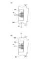
図2(a)は、本体部20の正面図であり、図2(b)は、図2(a)のA−A線における断面図である。把持部30は、使用者が片手で把持可能な程度の棒状に形成されており、内部に駆動部22及び表示部50の電源となるバッテリー31が収容されている。 FIG. 2A is a front view of the
操作部40は、4方向に操作可能なジョイスティック41及び複数のボタン42を備え、湾曲部13の操作方向の入力及び表示部50の各種設定等の入力が可能である。ジョイスティック41に代えて、操作する4方向に対応したキーやボタン等が採用されてもよい。 The
表示部50は、表示画面51と、撮像部11から送信された映像信号を表示画面51に表示可能に処理する画像処理部(後述)を備えている。表示画面51及び画像処理部としては、公知の各種機構を適宜選択して採用可能である。また、表示画面51として、いわゆるタッチパネル型のディスプレイを採用し、操作部40のボタン42の機能を持たせてもよい。 The
駆動部22は、筐体部21に着脱可能に取り付けられる外装体23と、外装体23の内部に収容された駆動機構60及び光源部70と、光源部70と熱的に接続された放熱部80とを備えている。 The
駆動機構60は、駆動源であるモータ61と、モータ61によって回転されるプーリ62との組を2つ備えている。モータ61とプーリ62との連動態様に特に制限はなく、モータ61のシャフトにプーリ62が取り付けられてもよいし、当該シャフトとプーリ62の回転軸とがベルト等の動力伝達部材によって接続されてもよい。 The
湾曲部13に接続された伝達部材である4本のアングルワイヤのうち、図2(a)のA−A線と平行かつ挿入部10の軸線から離間する2方向(以下、「上下方向」と称する。)に湾曲部13を湾曲させるための2本のアングルワイヤ14A及び14Bは、一方のプーリ62Aに接続されている。また、上下方向と直交しかつ挿入部10の軸線から離間する2方向(以下、「左右方向」と称する。)に湾曲部13を湾曲させるための2本のアングルワイヤ14C及び14Dは、他方のプーリ62Bに接続されている。
このような構成により、2つのモータ61を回転させて対応するプーリ62A、62Bを回転させ、アングルワイヤ14Aと14Bとの対及びアングルワイヤ14Cと14Dとの対を挿入部10に対して所望量相対移動させることができる、その結果、所望の方向に湾曲部13を湾曲させることができる。Of the four angle wires that are transmission members connected to the bending
With such a configuration, the two
光源部70は、発光部材である発光素子、例えば、LED(発光ダイオード)71と、LED71に接続されたライトガイド72とを備えている。ライトガイド72は、外装体23の外部に出て外装体23と接続された挿入部10内に進入し、挿入部10内を通って照明部12と接続されている。 The
放熱部80は金属等の熱伝導性の良好な材料からなり、外装体23と挿入部10との接続部位に取り付けられている。放熱部80の一部は外装体23の内部に進入し、LED71と熱的に接続されている。放熱部80は、挿入部10の軸線方向に延びる複数の第1フィン81と、挿入部10の径方向に延びる複数の円盤状の第2フィン82とを有し、本体部20の外部に露出した第1フィン81及び第2フィン82によって、LED71の発する熱を本体部20の外部へ逃がすヒートシンクとして機能する。 The
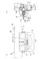
図3は、本体部20を下方(表示部50が設けられた側と反対側)から見た状態を、一部断面で示す図である。外装体23は、樹脂等からなり、図2(b)及び図3に示すように、内部に駆動機構60、LED71等を収容する収容部24と、収容部24に接続されて、放熱部80の周囲を覆って外部との接触を抑制する遮蔽部25とを備えている。 FIG. 3 is a partial cross-sectional view of the
収容部24は略箱状に形成されている。収容部24の第一の端部24Aには、筐体部21との接続に使用するコネクタ26が設けられている。一方、第一の端部24Aと反対側の第二の端部24Bは、図3に示すように、上下方向及び左右方向の寸法が第一の端部24Aよりも大きくなっており、寸法が変化する部分に段差24Cが形成されている。段差24Cには、全周にわたって弾性変形可能材料からなる環状の密閉部材27が取り付けられている。 The
遮蔽部25は、収容部24の第二の端部24Bから挿入部10の先端側に向かって延びるように形成されており、放熱部80の上方に延びる天板部25Aと、放熱部80の左右に延びる2箇所の側壁部25Bとを有する。図3に示すように、放熱部80の下方には遮蔽部25は設けられていない。
天板部25A及び側壁部25Bの寸法には特に制限はないが、後述するように、使用者が不用意に放熱部80に触れることがないよう、放熱部80の上方及び側方が完全に覆われる程度の寸法に設定されるのが好ましい。The shielding
The dimensions of the
天板部25Aには、貫通孔28が設けられている。放熱部80の下方は遮蔽部25によって覆われていないので、貫通孔28を通って放熱部80周囲の空気が上下方向に流通可能である。すなわち、貫通孔により、放熱部80周囲の空気の流通が促進される。
貫通孔28の寸法に特に制限はないが、空気を好適に流通させる観点からは大きい方がよく、使用者が放熱部80に触れることを抑制する観点からは一般的な人間の指が入らないような寸法設定が好ましい。したがって、一般的な人間の指が挿通不能な形状で、かつできるだけ大きく設定されるのが好ましい。A through
Although there is no restriction | limiting in particular in the dimension of the through-
図2(b)及び図3に示すように、駆動部22の第一の端部24Aは、筐体部21において表示部50の下方に設けられた空間である格納部21Aに挿入される。そして、コネクタ26が格納部21Aに設けられた図示しない受け部と接続されることにより、筐体部21と駆動部22とが着脱自在に接続されて一体の本体部20となる。このとき、図3に示すように、それぞれ筐体部21と駆動部22に設けたフック21Bと22Aとを連結部材29で連結し、駆動部22が意図しないタイミングで筐体部21から脱落することを防止してもよい。 As shown in FIGS. 2B and 3, the
筐体部21と駆動部22とが一体となった内視鏡装置1の本体部20は、把持部30を把持することによって片手で把持可能な程度の大きさ及び重さとなっており、把持部30を把持した状態で操作部40のジョイスティック41やボタン42を操作することが可能である。 The
図4は、内視鏡装置1の各部の電気的つながりを示すブロック図である。筐体部21において、操作部40は表示部50の表示画面51及び画像処理部52と接続されている。バッテリー31は、表示画面51と接続されている。
コネクタ26を介して筐体部21と駆動部22とを接続すると、バッテリー31と駆動機構60及LED71とが接続され、これらの機構に電力が供給される。同時に、挿入部10の撮像部11と画像処理部52とが接続され、駆動機構60と操作部40とが接続される。
本実施形態では、駆動部22及び駆動部22に接続された挿入部10が一体の挿入部ユニット90となっており、撮像部11の設定や挿入部10の長さが異なる複数の挿入部ユニットを、被検物の種類や内視鏡装置1の使用目的等に併せて交換することが可能である。FIG. 4 is a block diagram showing the electrical connection of each part of the
When the
In the present embodiment, the
上記のように構成された内視鏡装置1の使用時の動作について説明する。
まず使用者は、1つの挿入部ユニット90を選択して駆動部22の第一の端部24Aを格納部21Aに差込み、コネクタ26と受け部とを接続する。このとき、収容部24の段差24Cに取り付けられた密閉部材27が収容部24と格納部21Aとの間の隙間を塞ぎ、筐体部21と駆動部22とが水密を保って接続される。接続後、使用者は内視鏡装置1を起動する。The operation at the time of use of the
First, the user selects one
使用者は、挿入部10を被検物の内部に挿入する。撮像部11の視野は照明部12によって照明され、撮像部11の取得した映像信号は画像処理部52で処理されて、表示画面51に被検物内部の画像が表示される。 The user inserts the
使用者は表示画面51に表示された画像を確認しつつ、必要に応じて操作部40を操作して挿入部10の先端の向きを変えながら、挿入部10の先端を観察部位へと進める。挿入部10の先端が観察部位に到達したら、使用者は湾曲部13を所望の向きに湾曲させて、対象部位の観察を行う。 While confirming the image displayed on the
内視鏡装置1の使用時間が長くなるにつれて、光源部70のLED71が高温となる。LED71の発する熱は、LED71と熱的に接続された放熱部80に伝わり、第1フィン81及び第2フィン82から本体部20の外部に放散される。放熱部80の周囲の空気は、遮蔽部25に設けられた貫通孔28や遮蔽部25に覆われていない放熱部80の下方から好適に放散される。これにより、収容部24内に収容された各機構に対する熱の悪影響が抑制される。 As the usage time of the
挿入部ユニット90を別のものに交換する際は、挿入部10を被検物から抜去し、内視鏡装置1の電源をオフにする。そして、一方の手で把持部30を把持しつつ、他方の手で挿入部10の基端側あるいは駆動部22の第二の端部24B付近を把持して駆動部22を筐体部21から引き抜く。 When the
内視鏡装置1のように、LED71等の発光部材が本体部20内に配置されている場合、電源をオフにして間もないときは、放熱部80は高温であることが多く、上述した駆動部22の引き抜き操作には細心の注意が必要である。本実施形態の内視鏡装置1では、遮蔽部25が放熱部80の上方及び側方を覆っており、貫通孔28の寸法等は、一般的な人間の指が挿通不能に設定されているため、駆動部22の引き抜き操作時や内視鏡装置1の持ち運び時等に、使用者が高温となった放熱部80に触れることが好適に抑制される。 When the light emitting member such as the
本実施形態の内視鏡装置1によれば、使用中及び使用後にLED71の熱が伝わって高温となる放熱部80の周囲の少なくとも一部を遮蔽部25が覆っているので、放熱部80が使用者の体の一部に接触することが好適に抑制される。したがって、使用中に放熱部80を過度に意識する必要がなく、片手で把持可能でありながら、使い勝手のよい内視鏡装置とすることができる。 According to the
また、遮蔽部25の天板部25Aには貫通孔28が設けられているので、放熱部80周囲の空気が上下方向に好適に流通される。したがって、放熱部80の熱が好適に放散され、LED71の熱を効率よく外部に逃がすことができる。 Moreover, since the through-
本実施形態では、天板部25Aに1つの貫通孔28が設けられている例を説明したが、これに代えて、図5(a)に示す変形例のように、天板部25Aに複数の小径の貫通孔28Aが形成されてもよい。また、図5(b)に示す変形例のように、貫通孔28に空気を流通可能な網目状部材91が取り付けられてもよい。これらのような構成でも、使用者の放熱部80への接触を抑制しつつ、放熱部80周囲の空気の流通を促進することができる。網目状部材を用いるのに代えて貫通孔にリブを渡し架けることも可能である。なお、このような網目状部材やリブを放熱部80の下方に設けて、より確実に使用者の放熱部80への接触を抑制することも可能である。 In the present embodiment, an example in which one through
また、天板部25Aに貫通孔を設けるのに代えて、2枚の側壁部28Bに貫通孔を設けて放熱部80周囲の空気を流通させてもよい。ただし、放熱部80で暖められた空気は上昇しやすいこと、及び駆動部22の引き抜き操作においては側壁部25Bが把持されやすいことを考慮すると、天板部25Aに貫通孔が設けられるのがより好ましい。 Further, instead of providing a through hole in the
さらに、駆動部22の引き抜き操作が行いやすくなるように、図6(a)及び図6(b)に示すように、凹部93や凹凸部94が側壁部25Bに形成されてもよい。 Furthermore, as shown in FIG. 6A and FIG. 6B, a
次に、本発明の第2実施形態について、図7から図9を参照して説明する。本実施形態の内視鏡装置101と、上述の第1実施形態の内視鏡装置1との異なるところは、遮蔽部の形状である。なお、以降の各実施形態の説明において、既に説明した実施形態と共通する構成については、同一の符号を付して重複する説明を省略する。 Next, a second embodiment of the present invention will be described with reference to FIGS. The difference between the
図7(a)は、内視鏡装置101の本体部110の正面図であり、図7(b)は図7(a)のB−B線における部分断面図である。駆動部22の外装体111には、遮蔽部25に代えて遮蔽部112が設けられている。 Fig.7 (a) is a front view of the main-
遮蔽部112は、可撓性を有する帯状の第一部材113及び第二部材114を備えている。第一部材113は、樹脂等で形成され、自身の幅方向を湾曲部13の上下方向と平行にして、図8に示すように、放熱部80の第1フィン81の側方及び前方を環状に取り囲んで覆うように配置されている。第一部材113の長手方向の両端は、ビス115等によって収容部24の第二の端部24Bに固定されている。 The shielding
第二部材114は、第一部材113と同様の材料で形成されており、第1端部114Aが放熱部80よりも挿入部10側で第一部材113と接続されている。第二部材114は、放熱部80の上方を覆うように外装体111に向かって延び、第2端部114Bはビス115等によって収容部24の第二の端部24Bに固定されている。 The
第二部材114には、挿入部10との干渉を防ぐためのスリット114Cが形成されている。スリット114Cは第2端部114Bまで延びており、第2端部114Bは二股に分かれている。挿入部10との干渉を防ぐ形状はこの形状には限定されず、第1端部114A側がスリット114Cによって二股に分かれるように形成されても良い。また、端部を二股に分けないような孔や長孔等が第二部材114に形成されてもよいし、挿入部10を左右から挟むように2本の別個の第二部材が設けられても良い。さらに、第一部材113にスリット等の干渉を防ぐための形状が設けられても良い。 The
上記のように構成された内視鏡装置101においては、放熱部80の側方や上方から使用者の指等の体の一部が接近すると、まず遮蔽部112の第一部材113や第二部材114と接触しやすい。したがって、内視鏡装置101の使用中に高温となった放熱部80に使用者が接触することを好適に防止することができる。 In the
駆動部22を筐体部21から取り外す際、使用者は第一部材113に指を掛けて、筐体部21から離間するように駆動部22を引く。すると、帯状の第一部材113は、図9に示すように挿入部10の先端側に向かって変形するため、第一部材113に掛けた指等が放熱部80から遠ざかり、放熱部80に触れにくくなる。 When removing the
本実施形態の内視鏡装置101においても、放熱部80が使用者の体の一部に接触することが好適に抑制され、使い勝手のよい内視鏡装置とすることができる。
また、遮蔽部112が帯状の第一部材113及び第二部材114で形成されているので、遮蔽部112を、駆動部22を筐体部21から取り外す際の取手として使用することができる。このため、駆動部の外装体を小型化することができ、本体部110の使い勝手をさらに向上させることができる。Also in the
Further, since the shielding
本実施形態において、第一部材113及び第二部材114の幅や長さ等の各種寸法は適宜設定されて良い。例えば、長さについては、図8に示すように、第一部材113と放熱部80との間に適度な隙間ができる程度に設定すると、指を掛けるために第一部材113が形成する環の中に指等を挿入する際に指等が放熱部80に触れにくく、好ましい。また、第一部材113の幅寸法を、第1フィン81及び第2フィン82を含む放熱部80全体の上下方向の寸法程度に設定すると、放熱部80全体の側方を覆うことができ、放熱部80への接触をより好適に抑制することができる。なお、遮蔽部112によって過度に放熱部80の周囲を覆ってしまうと、放熱部80周囲の空気の流れが悪くなって冷却効率が低下するため、遮蔽部と放熱部との間には適度な隙間が確保されるのが好ましい。
また、本実施形態においては、遮蔽部が第一部材及び第二部材の二種類の部材からなる例を説明したが、これに代えて、第一部材及び第二部材のいずれか一方のみで遮蔽部が形成されてもよい。In the present embodiment, various dimensions such as the width and length of the
Moreover, in this embodiment, although the shielding part demonstrated the example which consists of two types of members, a 1st member and a 2nd member, it replaces with this and shields only with any one of a 1st member and a 2nd member. A part may be formed.
次に、本発明の第3実施形態について、図10から図13を参照して説明する。本実施形態の内視鏡装置121と、上述の各実施形態の内視鏡装置との異なるところは、放熱部及び遮蔽部の形状である。 Next, a third embodiment of the present invention will be described with reference to FIGS. The difference between the
図10は、内視鏡装置121の本体部130を側方から見た部分断面図であり、図11は本体部130を一部断面で示す部分底面図である。図10及び図11に示すように、駆動部22の外装体111には、遮蔽部25に代えて遮蔽部131が設けられている。放熱部80Aは、第1フィン81を有さず、円盤状の第2フィン82のみを備えている。 FIG. 10 is a partial cross-sectional view of the
遮蔽部131は、径の異なる複数の筒状部材132が軸線方向に相対移動可能となるように略同軸に配置された、公知のテレスコピック構造を有する。複数の筒状部材132は、挿入部10の先端側から本体部130に向かうにつれて徐々に径が大きくなるように並べられている。各々の筒状部材132の先端側には、径方向内側に突出する係止部133が設けられ、自身の先端側に位置する筒状部材の基端側において、径方向外側に突出するフランジ134と係合することによって、各筒状部材が脱落しないように連結されている。図11に示すように、最も先端側の筒状部材132Aには、径方向外側に突出するツマミ135が設けられている。最も基端側の筒状部材132Bは、収容部24の第二の端部24Bに固定されている。 The shielding
内視鏡装置121の使用時には、図12に示すように、遮蔽部131は第二の端部24B側に折りたたまれ、放熱部80Aが露出されて、放熱部80Aの熱が効率よく外部に放散される。内視鏡装置121の使用中は、放熱部80Aに使用者の手等が接近することは多くないため、大きな問題はない。 When the
駆動部22を筐体部21から取り外す際、使用者はツマミ135を把持して挿入部10の先端側に引く。すると、図10及び図11に示すように、遮蔽部131の各筒状部材132が、係止部133とフランジ134とが係合するまで挿入部10の先端側に移動する。これにより遮蔽部131が挿入部10の先端側に伸びて放熱部80Aの周囲を覆う。こうして、放熱部80Aに使用者の指等が接触しやすい駆動部22の交換時等に使用者が放熱部80Aと接触することが好適に抑制される。 When removing the
本実施形態の内視鏡装置121においても、放熱部80が使用者の体の一部に接触することが好適に抑制され、使い勝手のよい内視鏡装置とすることができる。
また、遮蔽部131を挿入部10の先端側に引くと、放熱部80Aの周囲を全周にわたって覆うことができるので、使用者の体の一部が比較的高温となった放熱部80Aと接触することをより確実に防ぐことができる。一方、遮蔽部131を折りたためば、放熱部80Aの周囲はほぼ完全に露出した状態となるので、内視鏡装置121の使用時においては、放熱部80Aの熱の放散を効率よく行うことができる。
このように、遮蔽部131は、その形状を変化させて、放熱部80Aの周囲を覆った状態と、放熱部80Aを覆わずに露出させた状態とに切り替え可能であるため、状況に応じて適切な形状に変化させることができ、使いやすい。Also in the
Further, when the shielding
Thus, since the shielding
本実施形態においては、遮蔽部131の複数の筒状部材132が、挿入部10の先端側から径の小さい順に配列された例を説明したが。これに代えて、図13に示す変形例のように、複数の筒状部材132を挿入部10の先端側から径の大きい順に配列して遮蔽部131Aを形成しても良い。この場合は、各筒状部材の基端側に係止部133が設けられ、隣接する筒状部材の先端側に設けられたフランジ134と係合する。なお、図13において、遮蔽部131Aの上半分は、遮蔽部131Aが折りたたまれた状態を示している。 In the present embodiment, the example in which the plurality of
遮蔽部131Aをこのように構成すると、遮蔽部131Aによって放熱部80Aの周囲が覆われた際に、遮蔽部131Aの先端側で、放熱部80Aとの間により大きな隙間が確保される、したがって、放熱部80A周囲の空気の流れがよくなり、遮蔽部131Aで放熱部80Aの周囲を覆ったときでも、放熱部80Aの冷却効率の低下を抑制することができる。また、引き出し操作時に接触する最も先端側の筒状部材がより放熱部80Aから離間することになるので、引き出し操作がさらに容易となる。 When the shielding
次に、本発明の第4実施形態について、図14から図17を参照して説明する。本実施形態の内視鏡装置141と、上述の各実施形態の内視鏡装置との異なるところは、遮蔽部の形状である。 Next, a fourth embodiment of the present invention will be described with reference to FIGS. The difference between the endoscope apparatus 141 of the present embodiment and the endoscope apparatuses of the above-described embodiments is the shape of the shielding portion.
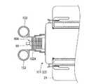
図14は、内視鏡装置141の本体部150を側方から見た部分断面図であり、図15は本体部150を一部断面で示す部分底面図である。図14及び図15に示すように、遮蔽部151は、遮蔽部131と同様のテレスコピック構造を有するが、筒状部材152の肉厚は筒状部材132よりも大きく設定されており、強度が高められている。また、図15に示すように、最も挿入部10の先端側に位置する筒状部材152Aには、軸線を挟んで互いに対向する二箇所に、環状の指掛部153が設けられている。 FIG. 14 is a partial cross-sectional view of the
内視鏡装置141の使用時は、図16に示すように、遮蔽部151が折りたたまれ、放熱部80Aの熱が効率よく放散される。交換等のために駆動部22を筐体部21から外すときは、使用者は指掛部153に指を挿入し、筐体部21から離間する方向に引く。すると、まず遮蔽部151が挿入部10の先端側に延びて、図14及び図15に示すように、放熱部80Aの周囲が遮蔽部151によって覆われる。指掛部153をさらに引き続けると、コネクタ26の係合が外れて、筐体部21から駆動部22が切り離される。 When the endoscope apparatus 141 is used, as shown in FIG. 16, the shielding
本実施形態の内視鏡装置141においては、駆動部22の取り外し時に指掛部153を引く操作に連動して放熱部80Aの周囲が遮蔽部151によって覆われ、使用者の体の一部が不用意に放熱部80Aに接触することが抑制される。したがって、放熱部80Aを意識することなく容易かつ安全に挿入部ユニットの交換等を行うことができ、使い勝手のよい内視鏡装置とすることができる。 In the endoscope apparatus 141 of the present embodiment, the periphery of the
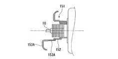
本実施形態の遮蔽部151においても、図17に示す変形例のように、複数の筒状部材152が挿入部10の先端側から径の大きい順に配列されてもよい。また、指掛部の形状も環状に限らず、図17に示すようなフック状の指掛部153Aであってもよい。
また、駆動部22が筐体部21から切り離されると、重量のある外装体111側が下方に移動しようとし、筒状部材152Aと指掛部との接続部位に大きな力が作用する。これを好適に逃がすことができるように、指掛部153等を、回動軸等を用いて筒状部材152Aの外周面の接続部位に対して平行な面上で回動可能に取り付けてもよい。Also in the shielding
Further, when the
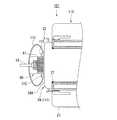
次に、本発明の第5実施形態について、図18から図20を参照して説明する。本実施形態の内視鏡装置161と、上述の各実施形態の内視鏡装置との異なるところは、遮蔽部の形状である。 Next, a fifth embodiment of the present invention will be described with reference to FIGS. The difference between the
図18は、内視鏡装置161の本体部170の正面図であり、図19は本体部170を一部断面で示す部分底面図である。図18及び図19に示すように、内視鏡装置161には、遮蔽部25に代えて遮蔽部171が設けられている。 18 is a front view of the
遮蔽部171は、挿入部10の軸線方向に伸縮可能な伸縮部172を4つ備えている。各伸縮部172は、樹脂等で形成された複数の板状部材173が、複数の回動軸174で互いに回動可能に連結されて構成されている。
4つの伸縮部172は、図18に示すように、放熱部80Aの上下左右の4箇所にそれぞれ取り付けられている。各伸縮部172において最も挿入部10の先端側に位置する4枚の板状部材173Aは、いずれも枠体175に回動可能に取り付けられている。したがって、枠体175を挿入部10の軸線方向に移動させることによって4つの伸縮部172を一体に伸縮させることが可能である。The shielding
As shown in FIG. 18, the four
上記のように構成された本実施形態の内視鏡装置161の使用時の動作について説明する。
内視鏡装置161の使用中は、図19に示すように遮蔽部の各伸縮部172を挿入部10の軸線方向に縮めておき、放熱部80Aを露出させておく。これにより、放熱部80Aの熱が効率よく放散される。The operation at the time of use of the
During use of the
駆動部22の交換時等には、使用者は縮められた各伸縮部172のうち、挿入部10の軸線から離間する方向に突出した突出部176を挿入部10の軸線に向かって押し込む。このとき、挿入部10の軸線を挟んで対向する2箇所の突出部176を挟むように押し込んでもよい。
突出部176が押し込まれた伸縮部172は、図20に示すように、挿入部10の先端側に向かって延びる。このとき、延びる伸縮部の板状部材173Aに取り付けられた枠体175が挿入部10の先端側に移動するため、4箇所の伸縮部172すべてが連動して挿入部10の先端側に向かって延びる。その結果、放熱部80Aの上下左右が遮蔽部171に覆われて、使用者の体の一部が放熱部80Aに接触することが防止される。When replacing the
As shown in FIG. 20, the
本実施形態の内視鏡装置161においても、遮蔽部171によって放熱部80Aが使用者の体の一部に接触することが好適に抑制され、使い勝手のよい内視鏡装置とすることができる。
また、遮蔽部171の伸縮時に可動するのは、もっぱら各伸縮部172の突出部176における回動軸174であるので、上述したテレスコピック構造の遮蔽部に比べて、より少ない動作でスムーズに遮蔽部の形状を遮蔽状態と放熱状態とに切り替えることができる。Also in the
Further, since it is exclusively the
本実施形態においては、4箇所の伸縮部172が放熱部80Aの上下左右に取り付けられている例を説明したが、伸縮部の配置位置はこれには限られず、上下左右の4方向と角度をなして取り付けられてもよい。また、例えば下方には伸縮部を設けずに3方向に配置するといった設計変更も可能である。
さらに第4実施形態のように、最も挿入部10の先端側に位置する板状部材173Aに指掛部が設けられてもよい。In the present embodiment, an example has been described in which the four expansion /
Further, as in the fourth embodiment, a finger hook portion may be provided on the plate-
以上、本発明の各実施形態を説明したが、本発明の技術範囲は上記実施形態に限定されるものではなく、本発明の趣旨を逸脱しない範囲において種々の変更を加えることが可能である。 As mentioned above, although each embodiment of this invention was described, the technical scope of this invention is not limited to the said embodiment, A various change can be added in the range which does not deviate from the meaning of this invention.
例えば、上述の各実施形態においては、本体部において、筐体部と駆動部とが着脱自在である例を説明したが、この点は本発明の内視鏡装置に必須ではなく、筐体部と駆動部とが着脱不能であってもよい。ただし、筐体部と駆動部とが着脱自在であると、駆動部の着脱時等において使用者の体の一部が放熱部に接触する可能性が高まるため、特に本発明の内視鏡装置の構造によるメリットが大きい。
また、上述の各実施形態では、光源部の発光部材がLEDである例を説明したが、これ以外にも例えば、レーザダイオード(LD)等の他の発光素子や各種ランプ等の公知の各種構成を適宜選択して採用することが可能である。For example, in each of the above-described embodiments, an example in which the housing unit and the drive unit are detachable in the main body has been described. However, this point is not essential for the endoscope apparatus of the present invention. And the drive unit may not be detachable. However, if the housing part and the drive part are detachable, the possibility that a part of the user's body will come into contact with the heat radiating part when the drive part is attached or detached is increased. The advantages of this structure are great.
Further, in each of the above-described embodiments, an example in which the light emitting member of the light source unit is an LED has been described. In addition to this, for example, other known light emitting elements such as a laser diode (LD) and various known lamps Can be appropriately selected and employed.
さらに、放熱部の設置位置は、挿入部の基端に限られないので、放熱部の位置に応じて遮蔽部の設置位置も適宜設定することが可能である。
なお、上述の各実施形態で説明した構成や形状等は適宜組み合わせることが可能である。Furthermore, since the installation position of the heat dissipating part is not limited to the proximal end of the insertion part, the installation position of the shielding part can be appropriately set according to the position of the heat dissipating part.
The configurations, shapes, and the like described in the above embodiments can be combined as appropriate.
1、101、121、141、161 内視鏡装置
10 挿入部
11 撮像部(観察手段)
12 照明部
13 湾曲部
20、110、130、150、170 本体部
25、112、131、151、171 遮蔽部
28 貫通孔
40 操作部
50 表示部
70 光源部
71 LED(発光部材)
72 ライトガイド
80、80A 放熱部
113 第一部材
114 第二部材
132、132A、132B、152、152A 筒状部材
172 伸縮部
173 板状部材1, 101, 121, 141, 161
DESCRIPTION OF
72
Claims (6)
Translated fromJapanese前記挿入部の先端に設けられた観察手段と、
前記挿入部の先端に設けられ、前記観察手段の視野を照明する照明部と、
前記挿入部に接続され、前記観察手段の取得した画像を表示する表示部と、前記湾曲部を操作するための操作部と、把持した状態で前記操作部を操作可能な把持部と、を有し、片手で把持及び操作可能な大きさに形成された本体部と、
前記本体部に設けられ、照明光の光源となる発光部材と、前記照明部と前記発光部材とを接続するライトガイドとを有する光源部と、
少なくとも一部が前記本体部から突出して露出するように前記本体部に設けられ、前記発光部材と熱的に接続された放熱部と、
前記本体部から突出して設けられ、前記放熱部の周囲の少なくとも一部を覆い、前記放熱部の外部との接触を抑制する樹脂製の遮蔽部と、
を備え、
前記遮蔽部の先端は、前記放熱部の先端よりもさらに先端側に位置していることを特徴とする内視鏡装置。An insertion portion having a bending portion that is flexible and is formed to be long and can be bent;
An observation means provided at the tip of the insertion portion;
An illumination unit that is provided at a distal end of the insertion unit and illuminates a field of view of the observation unit;
A display unit connected to the insertion unit and displaying an image acquired by the observation unit; an operation unit for operating the bending unit; and a gripping unit capable of operating the operation unit in a gripped state. A main body formed in a size that can be grasped and operated with one hand;
A light source part provided in the main body part and serving as a light source of illumination light; and a light source part having a light guide connecting the illumination part and the light emitting member;
A heat dissipating part provided in the main body part so that at least a partprotrudes from the main body part and exposed, and is thermally connected to the light emitting member;
Protruding from the main body part, covering at least a part of the periphery of the heat dissipation part, and aresin shielding part for suppressing contact with the outside of the heat dissipation part,
Equipped witha,
The tip of the shield portion, the endoscope apparatus characterized that youhave located more frontward of the front end of the radiator portion.
Priority Applications (2)
| Application Number | Priority Date | Filing Date | Title |
|---|---|---|---|
| JP2009185760AJP5519211B2 (en) | 2009-08-10 | 2009-08-10 | Endoscope device |
| US12/852,597US8900132B2 (en) | 2009-08-10 | 2010-08-09 | Endoscope apparatus |
Applications Claiming Priority (1)
| Application Number | Priority Date | Filing Date | Title |
|---|---|---|---|
| JP2009185760AJP5519211B2 (en) | 2009-08-10 | 2009-08-10 | Endoscope device |
Publications (2)
| Publication Number | Publication Date |
|---|---|
| JP2011036365A JP2011036365A (en) | 2011-02-24 |
| JP5519211B2true JP5519211B2 (en) | 2014-06-11 |
Family
ID=43535332
Family Applications (1)
| Application Number | Title | Priority Date | Filing Date |
|---|---|---|---|
| JP2009185760AActiveJP5519211B2 (en) | 2009-08-10 | 2009-08-10 | Endoscope device |
Country Status (2)
| Country | Link |
|---|---|
| US (1) | US8900132B2 (en) |
| JP (1) | JP5519211B2 (en) |
Cited By (1)
| Publication number | Priority date | Publication date | Assignee | Title |
|---|---|---|---|---|
| US11369259B2 (en) | 2018-03-30 | 2022-06-28 | Olympus Corporation | Endoscopic device and heat radiator |
Families Citing this family (14)
| Publication number | Priority date | Publication date | Assignee | Title |
|---|---|---|---|---|
| HK1198738A1 (en) | 2011-05-03 | 2015-06-05 | Endosee股份有限公司 | Method and apparatus for hysteroscopy and endometrial biopsy |
| JP5540036B2 (en)* | 2012-03-26 | 2014-07-02 | 富士フイルム株式会社 | Endoscope |
| US9468367B2 (en) | 2012-05-14 | 2016-10-18 | Endosee Corporation | Method and apparatus for hysteroscopy and combined hysteroscopy and endometrial biopsy |
| US9622646B2 (en) | 2012-06-25 | 2017-04-18 | Coopersurgical, Inc. | Low-cost instrument for endoscopically guided operative procedures |
| US9195315B2 (en) | 2013-03-14 | 2015-11-24 | Xerox Corporation | Interactive control device and system including an integrated display |
| US20140275763A1 (en)* | 2013-03-15 | 2014-09-18 | Lucent Medical Systems, Inc. | Partially disposable endoscopic device |
| US9307672B2 (en)* | 2013-08-26 | 2016-04-05 | General Electric Company | Active cooling of inspection or testing devices |
| JP6717752B2 (en)* | 2014-04-04 | 2020-07-01 | ボストン サイエンティフィック サイムド,インコーポレイテッドBoston Scientific Scimed,Inc. | Medical devices for diagnosis and treatment |
| WO2016170941A1 (en)* | 2015-04-24 | 2016-10-27 | オリンパス株式会社 | Endoscope |
| US10702305B2 (en) | 2016-03-23 | 2020-07-07 | Coopersurgical, Inc. | Operative cannulas and related methods |
| JP6736322B2 (en)* | 2016-03-25 | 2020-08-05 | オリンパス株式会社 | Endoscope |
| US11259688B2 (en) | 2018-04-18 | 2022-03-01 | Duke University | Devices for assisting manipulation of input mechanisms of medical instruments |
| US11490790B2 (en) | 2018-07-18 | 2022-11-08 | Cook Medical Technologies Llc | Device for shielding endoscopic optics with a fluid barrier |
| USD979627S1 (en)* | 2021-03-16 | 2023-02-28 | Baker Hughes Holdings Llc | Video borescope housing |
Family Cites Families (22)
| Publication number | Priority date | Publication date | Assignee | Title |
|---|---|---|---|---|
| US3670811A (en)* | 1970-04-13 | 1972-06-20 | Young Radiator Co | Protection-sleeve for finned-tubes of heat-exchanger core-unit |
| US5373317B1 (en) | 1993-05-28 | 2000-11-21 | Welch Allyn Inc | Control and display section for borescope or endoscope |
| JPH09315882A (en)* | 1996-05-29 | 1997-12-09 | Komatsu Electron Metals Co Ltd | Device for producing semiconductor single crystal and production of semiconductor single crystal therewith |
| US5879289A (en)* | 1996-07-15 | 1999-03-09 | Universal Technologies International, Inc. | Hand-held portable endoscopic camera |
| JPH11113843A (en) | 1997-10-08 | 1999-04-27 | Nippon Koden Corp | Stylet with observation optics for endotracheal tube intubation |
| JP3478388B2 (en)* | 2000-06-30 | 2003-12-15 | 株式会社インターフェース | Cooling system |
| EP1618736A2 (en) | 2003-01-29 | 2006-01-25 | Everest-VIT, Inc. | Remote video inspection system |
| US7134993B2 (en) | 2004-01-29 | 2006-11-14 | Ge Inspection Technologies, Lp | Method and apparatus for improving the operation of a remote viewing device by changing the calibration settings of its articulation servos |
| WO2006086106A2 (en)* | 2005-01-10 | 2006-08-17 | Perceptron, Inc. | Optical snake |
| US8109981B2 (en)* | 2005-01-25 | 2012-02-07 | Valam Corporation | Optical therapies and devices |
| US8523764B2 (en)* | 2005-12-07 | 2013-09-03 | Siemens Energy, Inc. | Remote viewing apparatus |
| US7679041B2 (en) | 2006-02-13 | 2010-03-16 | Ge Inspection Technologies, Lp | Electronic imaging device with photosensor arrays |
| JP2008011992A (en)* | 2006-07-04 | 2008-01-24 | Olympus Medical Systems Corp | Endoscope |
| JP5226197B2 (en)* | 2006-08-25 | 2013-07-03 | オリンパス株式会社 | Endoscope guide tube and endoscope apparatus |
| US8213676B2 (en) | 2006-12-20 | 2012-07-03 | Ge Inspection Technologies Lp | Inspection apparatus method and apparatus comprising motion responsive control |
| US8118733B2 (en) | 2006-12-22 | 2012-02-21 | Ge Inspection Technologies, Lp | Heat protection systems and methods for remote viewing devices |
| US8514278B2 (en) | 2006-12-29 | 2013-08-20 | Ge Inspection Technologies Lp | Inspection apparatus having illumination assembly |
| US8767060B2 (en)* | 2007-10-26 | 2014-07-01 | Ge Inspection Technologies, Lp | Inspection apparatus having heat sink assembly |
| US7902990B2 (en) | 2007-10-26 | 2011-03-08 | Ge Inspection Technologies, Lp | Battery and power management for industrial inspection handset |
| US8253782B2 (en) | 2007-10-26 | 2012-08-28 | Ge Inspection Technologies, Lp | Integrated storage for industrial inspection handset |
| US8310604B2 (en) | 2007-10-26 | 2012-11-13 | GE Sensing & Inspection Technologies, LP | Visual inspection apparatus having light source bank |
| JP5284625B2 (en)* | 2007-11-13 | 2013-09-11 | オリンパスメディカルシステムズ株式会社 | Light source unit |
- 2009
- 2009-08-10JPJP2009185760Apatent/JP5519211B2/enactiveActive
- 2010
- 2010-08-09USUS12/852,597patent/US8900132B2/ennot_activeExpired - Fee Related
Cited By (1)
| Publication number | Priority date | Publication date | Assignee | Title |
|---|---|---|---|---|
| US11369259B2 (en) | 2018-03-30 | 2022-06-28 | Olympus Corporation | Endoscopic device and heat radiator |
Also Published As
| Publication number | Publication date |
|---|---|
| US20110034773A1 (en) | 2011-02-10 |
| JP2011036365A (en) | 2011-02-24 |
| US8900132B2 (en) | 2014-12-02 |
Similar Documents
| Publication | Publication Date | Title |
|---|---|---|
| JP5519211B2 (en) | Endoscope device | |
| JP5178239B2 (en) | Medical system | |
| WO2012086046A1 (en) | Endoscopic device | |
| JP5389731B2 (en) | Endoscope | |
| WO2012086083A1 (en) | Endoscopic device | |
| JP2011019570A (en) | Endoscope | |
| JP2006192201A (en) | Electric curving endoscope device | |
| JPWO2017126388A1 (en) | Medical light source device and medical observation system | |
| JP4526284B2 (en) | Endoscope device | |
| JP5248815B2 (en) | Endoscope | |
| US20210369091A1 (en) | Disposable light handle for endoscopy | |
| JP2015016097A (en) | Electric endoscope | |
| JP7148470B2 (en) | Endoscope | |
| JP5602619B2 (en) | Endoscope | |
| JP5969853B2 (en) | Endoscope | |
| JP2009045084A (en) | Endoscope operation device | |
| JP2005218569A (en) | Endoscope | |
| JP2019013388A (en) | Electronic equipment | |
| JP6736322B2 (en) | Endoscope | |
| JP2005102751A (en) | Endoscope | |
| JP2007244904A (en) | Endoscope | |
| JP4658536B2 (en) | Endoscope device | |
| JP5580538B2 (en) | Endoscope device | |
| JP2019016671A (en) | Substrate support structure for electronic equipment | |
| JP2009066048A (en) | Endoscope |
Legal Events
| Date | Code | Title | Description |
|---|---|---|---|
| A621 | Written request for application examination | Free format text:JAPANESE INTERMEDIATE CODE: A621 Effective date:20120629 | |
| A977 | Report on retrieval | Free format text:JAPANESE INTERMEDIATE CODE: A971007 Effective date:20130502 | |
| A131 | Notification of reasons for refusal | Free format text:JAPANESE INTERMEDIATE CODE: A131 Effective date:20130514 | |
| A521 | Request for written amendment filed | Free format text:JAPANESE INTERMEDIATE CODE: A821 Effective date:20130712 Free format text:JAPANESE INTERMEDIATE CODE: A523 Effective date:20130712 | |
| TRDD | Decision of grant or rejection written | ||
| A01 | Written decision to grant a patent or to grant a registration (utility model) | Free format text:JAPANESE INTERMEDIATE CODE: A01 Effective date:20140304 | |
| A61 | First payment of annual fees (during grant procedure) | Free format text:JAPANESE INTERMEDIATE CODE: A61 Effective date:20140403 | |
| R151 | Written notification of patent or utility model registration | Ref document number:5519211 Country of ref document:JP Free format text:JAPANESE INTERMEDIATE CODE: R151 | |
| S531 | Written request for registration of change of domicile | Free format text:JAPANESE INTERMEDIATE CODE: R313531 | |
| R350 | Written notification of registration of transfer | Free format text:JAPANESE INTERMEDIATE CODE: R350 | |
| R250 | Receipt of annual fees | Free format text:JAPANESE INTERMEDIATE CODE: R250 | |
| R250 | Receipt of annual fees | Free format text:JAPANESE INTERMEDIATE CODE: R250 | |
| R250 | Receipt of annual fees | Free format text:JAPANESE INTERMEDIATE CODE: R250 | |
| R250 | Receipt of annual fees | Free format text:JAPANESE INTERMEDIATE CODE: R250 | |
| S111 | Request for change of ownership or part of ownership | Free format text:JAPANESE INTERMEDIATE CODE: R313111 | |
| R371 | Transfer withdrawn | Free format text:JAPANESE INTERMEDIATE CODE: R371 | |
| S111 | Request for change of ownership or part of ownership | Free format text:JAPANESE INTERMEDIATE CODE: R313111 | |
| R371 | Transfer withdrawn | Free format text:JAPANESE INTERMEDIATE CODE: R371 | |
| S111 | Request for change of ownership or part of ownership | Free format text:JAPANESE INTERMEDIATE CODE: R313111 | |
| R250 | Receipt of annual fees | Free format text:JAPANESE INTERMEDIATE CODE: R250 | |
| R350 | Written notification of registration of transfer | Free format text:JAPANESE INTERMEDIATE CODE: R350 | |
| R250 | Receipt of annual fees | Free format text:JAPANESE INTERMEDIATE CODE: R250 | |
| R250 | Receipt of annual fees | Free format text:JAPANESE INTERMEDIATE CODE: R250 |