JP5516180B2 - Oscillator and electronic device - Google Patents
Oscillator and electronic deviceDownload PDFInfo
- Publication number
- JP5516180B2 JP5516180B2JP2010166509AJP2010166509AJP5516180B2JP 5516180 B2JP5516180 B2JP 5516180B2JP 2010166509 AJP2010166509 AJP 2010166509AJP 2010166509 AJP2010166509 AJP 2010166509AJP 5516180 B2JP5516180 B2JP 5516180B2
- Authority
- JP
- Japan
- Prior art keywords
- oscillation
- acoustic lens
- units
- oscillation units
- oscillation device
- Prior art date
- Legal status (The legal status is an assumption and is not a legal conclusion. Google has not performed a legal analysis and makes no representation as to the accuracy of the status listed.)
- Expired - Fee Related
Links
- 230000010355oscillationEffects0.000claimsdescription76
- 239000011159matrix materialSubstances0.000claimsdescription10
- 230000002093peripheral effectEffects0.000claimsdescription2
- 239000000463materialSubstances0.000description9
- KDLHZDBZIXYQEI-UHFFFAOYSA-NPalladiumChemical compound[Pd]KDLHZDBZIXYQEI-UHFFFAOYSA-N0.000description4
- 230000005540biological transmissionEffects0.000description4
- 238000006243chemical reactionMethods0.000description4
- 230000000694effectsEffects0.000description4
- 238000000034methodMethods0.000description4
- 229910052709silverInorganic materials0.000description4
- 239000004332silverSubstances0.000description4
- 230000005520electrodynamicsEffects0.000description3
- 238000011161developmentMethods0.000description2
- 230000018109developmental processEffects0.000description2
- 230000007274generation of a signal involved in cell-cell signalingEffects0.000description2
- 238000004519manufacturing processMethods0.000description2
- 229910052763palladiumInorganic materials0.000description2
- 229910000906BronzeInorganic materials0.000description1
- OAICVXFJPJFONN-UHFFFAOYSA-NPhosphorusChemical compound[P]OAICVXFJPJFONN-UHFFFAOYSA-N0.000description1
- RTAQQCXQSZGOHL-UHFFFAOYSA-NTitaniumChemical compound[Ti]RTAQQCXQSZGOHL-UHFFFAOYSA-N0.000description1
- JRPBQTZRNDNNOP-UHFFFAOYSA-Nbarium titanateChemical compound[Ba+2].[Ba+2].[O-][Ti]([O-])([O-])[O-]JRPBQTZRNDNNOP-UHFFFAOYSA-N0.000description1
- 229910002113barium titanateInorganic materials0.000description1
- 239000010974bronzeSubstances0.000description1
- 230000008602contractionEffects0.000description1
- KUNSUQLRTQLHQQ-UHFFFAOYSA-Ncopper tinChemical compound[Cu].[Sn]KUNSUQLRTQLHQQ-UHFFFAOYSA-N0.000description1
- 230000007423decreaseEffects0.000description1
- 230000005684electric fieldEffects0.000description1
- 239000007772electrode materialSubstances0.000description1
- 230000001771impaired effectEffects0.000description1
- 229910010272inorganic materialInorganic materials0.000description1
- 239000011147inorganic materialSubstances0.000description1
- 230000002452interceptive effectEffects0.000description1
- 229910052751metalInorganic materials0.000description1
- 239000002184metalSubstances0.000description1
- 238000010295mobile communicationMethods0.000description1
- 239000011368organic materialSubstances0.000description1
- 230000003647oxidationEffects0.000description1
- 238000007254oxidation reactionMethods0.000description1
- 230000010287polarizationEffects0.000description1
- 230000000644propagated effectEffects0.000description1
- 239000011347resinSubstances0.000description1
- 229920005989resinPolymers0.000description1
- 230000000452restraining effectEffects0.000description1
- 239000000523sampleSubstances0.000description1
- 229910001220stainless steelInorganic materials0.000description1
- 239000010935stainless steelSubstances0.000description1
Images


Landscapes
- Details Of Audible-Bandwidth Transducers (AREA)
- Transducers For Ultrasonic Waves (AREA)
- Circuit For Audible Band Transducer (AREA)
Description
Translated fromJapanese本発明は、発振装置及び電子機器に関する。 The present invention relates to an oscillation device and an electronic apparatus.
近年、携帯電話やラップトップ型コンピュータなどの携帯端末などの需要が拡大している。特にテレビ電話や動画再生、ハンズフリー電話機能などの音響機能を商品価値とした薄型の携帯端末の開発が進められている。これらの開発の中で、小型でかつ出力が大きい電気音響変換器の要求が高まっている。従来、携帯電話等の電子機器には、電気音響変換器として動電型電気音響変換器が利用されている。この動電型電気音響変換器は、永久磁石とボイスコイルと振動膜から構成されている。しかしながら動電型電気音響変換器は、その動作原理及び構造から、薄型化には限界がある。そこで、圧電振動子を電気音響変換器であるパラメトリックスピーカして使用することが期待されている。 In recent years, demand for mobile terminals such as mobile phones and laptop computers has been increasing. In particular, the development of thin mobile terminals with commercial functions such as videophones, video playback, and hands-free phone functions is underway. In these developments, there is an increasing demand for electroacoustic transducers that are small in size and large in output. Conventionally, an electrodynamic electroacoustic transducer is used as an electroacoustic transducer in an electronic device such as a mobile phone. This electrodynamic electroacoustic transducer is composed of a permanent magnet, a voice coil, and a diaphragm. However, the electrodynamic electroacoustic transducer is limited in thickness because of its operation principle and structure. Therefore, it is expected to use the piezoelectric vibrator as a parametric speaker that is an electroacoustic transducer.
またパラメトリックスピーカとしての用途ではないが、特許文献1〜3には、超音波を探触子として用いるときに、超音波の発信源に音響レンズを取り付けることが記載されている。これらのうち特許文献1および3に記載の技術は、音響レンズを用いて超音波を拡散させるものである。また特許文献2に記載の技術は、直線状に並べた複数の発信源それぞれから発振された超音波を個々に集束させることにより、超音波を直線状に集束させるものである。 Although not used as a parametric speaker, Patent Documents 1 to 3 describe attaching an acoustic lens to an ultrasonic wave transmission source when ultrasonic waves are used as a probe. Among these, the techniques described in Patent Documents 1 and 3 diffuse ultrasonic waves using an acoustic lens. The technique described in Patent Document 2 focuses the ultrasonic waves linearly by individually focusing the ultrasonic waves oscillated from the plurality of transmission sources arranged in a straight line.
パラメトリックスピーカの復調方式の一つに、マトリクス状に配置されている発信源から発振された超音波を重ね合わせて干渉させることにより、可聴音を復調させるものがある。この方式を採用する場合、複数の発信源の発振方向を個々に変える必要があり、構造が複雑になってしまう。 One of the demodulation methods of a parametric speaker is one that demodulates audible sound by superimposing and interfering with ultrasonic waves oscillated from transmission sources arranged in a matrix. When this method is adopted, it is necessary to individually change the oscillation directions of a plurality of transmission sources, and the structure becomes complicated.
本発明の目的は、パラメトリックスピーカとして機能し、かつ構造を単純化できる発振装置及び電子機器を提供することにある。 An object of the present invention is to provide an oscillation device and an electronic apparatus that function as a parametric speaker and can simplify the structure.
本発明によれば、それぞれが振動子を有していてマトリクス状に配置されている複数の発振部と、
前記複数の発振部に、可聴域の音声データを変調した超音波発振用のデータを入力することにより、前記複数の発振部をパラメトリックスピーカとして機能させる制御部と、
前記複数の発振部に対向して設けられ、前記複数の発振部それぞれから発振された超音波を集束させる方向に屈曲させる音響レンズ系と、
を備える発振装置が提供される。According to the present invention, a plurality of oscillating portions each having a vibrator and arranged in a matrix,
A control unit that causes the plurality of oscillation units to function as a parametric speaker by inputting ultrasonic oscillation data obtained by modulating audio data in an audible range to the plurality of oscillation units;
An acoustic lens system that is provided facing the plurality of oscillating units and bends in a direction in which ultrasonic waves oscillated from each of the plurality of oscillating units are focused; and
An oscillation device is provided.
本発明によれば、筐体と、
前記筐体の内部に収容された発振装置と、
を備え、
前記発振装置は、
それぞれが振動子を有していてマトリクス状に配置されている複数の発振部と、
前記複数の発振部に、可聴域の音声データを変調した超音波発振用のデータを入力することにより、前記複数の発振部をパラメトリックスピーカとして機能させる制御部と、
前記複数の発振部に対向して設けられ、前記複数の発振部それぞれから発振された超音波を集束させる方向に屈曲させる音響レンズ系と、
を備える電子機器が提供される。According to the present invention, a housing;
An oscillation device housed in the housing;
With
The oscillator is
A plurality of oscillators each having a vibrator and arranged in a matrix;
A control unit that causes the plurality of oscillation units to function as a parametric speaker by inputting ultrasonic oscillation data obtained by modulating audio data in an audible range to the plurality of oscillation units;
An acoustic lens system that is provided facing the plurality of oscillating units and bends in a direction in which ultrasonic waves oscillated from each of the plurality of oscillating units are focused; and
An electronic device is provided.
本発明によれば、パラメトリックスピーカとして機能し、かつ構造を単純化できる発振装置及び電子機器を提供することができる。 According to the present invention, it is possible to provide an oscillation device and an electronic apparatus that function as a parametric speaker and can simplify the structure.
以下、本発明の実施の形態について、図面を用いて説明する。尚、すべての図面において、同様な構成要素には同様の符号を付し、適宜説明を省略する。 Hereinafter, embodiments of the present invention will be described with reference to the drawings. In all the drawings, the same reference numerals are given to the same components, and the description will be omitted as appropriate.
(第1の実施形態)
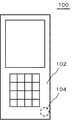
図1は、第1の実施形態に係る電子機器100の構成を示す断面図である。図2は電子機器100の平面図である。電子機器100は、例えば携帯通信端末であり、筐体102、発振装置110、及び制御部50を備えている。だたし電子機器100は、ラップトップ型パーソナルコンピュータ、小型ゲーム機器などであってもよい。発振装置110は筐体102の内部に収容されている。発振装置110は、複数の発振部を備えている。各発振部は、それぞれが振動子を有しており、マトリクス状に配置されている。複数の発振部は制御部50によって出力が制御されている。制御部50は、筐体102の内部に収容されており、発振部に、可聴域の音声データを変調した超音波発振用のデータを入力することにより、発振装置110をパラメトリックスピーカとして機能させる。筐体102にはスピーカ孔104が設けられている。スピーカ孔104は、発振装置110の発振面に対向しており、発振装置110の音響レンズ30によって塞がれている。音響レンズ30は、複数の発振部それぞれから発振された超音波を、一点に集束させる方向に屈曲させる。以下、詳細に説明する。(First embodiment)
FIG. 1 is a cross-sectional view illustrating a configuration of an
発振装置110は、複数の振動部材10、複数の圧電振動子20、及び支持体40を備えている。振動部材10はシート形状を有している。上記した発振部は、一組の振動部材10と圧電振動子20により構成されている。振動部材10と圧電振動子20の組がマトリクス状に配置されることにより、発振装置110の主要部が構成される。支持体40は枠状の部材であり、内側面が振動部材10の縁を支持している。複数の振動部材10は、同一平面を構成するように配置されている。 The
振動部材10は、圧電振動子20から発生した振動によって振動する。また振動部材10は、圧電振動子20の基本共振周波数を調整する。機械振動子の基本共振周波数は、負荷重量と、コンプラインスに依存する。コンプラインスは振動子の機械剛性であるため、振動部材10の剛性を制御することで、圧電振動子20の基本共振周波数を制御できる。なお、振動部材10の厚みは5μm以上500μm以下であることが好ましい。また、振動部材10は、剛性を示す指標である縦弾性係数が1Gpa以上500GPa以下であることが好ましい。振動部材10の剛性が低すぎる場合や、高すぎる場合は、機械振動子として特性や信頼性を損なう可能性が出てくる。なお、振動部材10を構成する材料は、金属や樹脂など、脆性材料である圧電振動子20に対して高い弾性率を持つ材料であれば特に限定されないが、加工性やコストの観点からリン青銅やステンレスなどが好ましい。 The
本実施形態において圧電振動子20は矩形、例えば正方形である。圧電振動子20の外縁は、振動部材10のうち支持体40に支持されている部分より内側に位置している。ただし圧電振動子20の形状は、矩形に限定されない。 In the present embodiment, the
また発振装置は、発振回路として制御部50及び信号生成部54を有している。信号生成部54は、圧電振動子20に入力する電気信号を生成する。制御部50は、外部から入力された音声データを変調して超音波発振用のデータを生成し、このデータを、信号生成部54を介して圧電振動子20に入力する。 The oscillation device has a
音響レンズ30は、超音波、例えば周波数が20kHz以上の音波を集束する方向に九曲させる。本実施形態において音響レンズ30は、一つの音響レンズ30で上記したマトリクス状の複数の発振部に対応している。そして音響レンズ30は、周縁部が支持体40によって支持されている。音響レンズ30は、例えば振動部材10に対向する面が凹状になっている。音響レンズ30は、外部に面している面が平坦になっているのが好ましい。 The
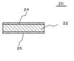
図3は、圧電振動子20の厚さ方向の構成を示す断面図である。圧電振動子20は、圧電体22、上面電極24、及び下面電極26を有している。圧電体22は厚さ方向に分極している。圧電体22を構成する材料は、圧電効果を有する材料であれば、無機材料及び有機材料のいずれであってもよい。ただし、電気機械変換効率が高い材料、例えばジルコン酸チタン酸塩(PZT)やチタン酸バリウム(BaTiO3)であるのが好ましい。圧電体22の厚さhは、例えば10μm以上1mm以下である。厚さh1が10μm未満の場合、発振装置の製造時に圧電振動子20が破損する可能性が出てくる。また厚さh1が1mm超の場合、電気機械変換効率が低くなりすぎてしまい。十分な大きさの振動を得られない。その理由は、圧電振動子20の厚さが厚くなると、圧電振動子内における電界強度は反比例して小さくなるためである。また圧電体22の厚さは、互いに等しくてもよいし、異なっていてもよい。FIG. 3 is a cross-sectional view illustrating the configuration of the
上面電極24及び下面電極26を構成する材料は特に限定されないが、例えば、銀や銀/パラジウムを使用することができる。銀は低抵抗な汎用的な電極材料して使用されているため、製造プロセスやコストなどに利点がある。銀/パラジウムは耐酸化に優れた低抵抗材料であるため、信頼性の観点から利点がある。また、上面電極24及び下面電極26の厚さh2は特に限定されないが、その厚さh2が1μm以上50μm以下であるのが好ましい。厚さh2が1μm未満では、上面電極24及び下面電極26を均一に成形することが難しくなり、その結果、電気機械変換効率が低下する可能性がある。また、上面電極24及び下面電極26の膜厚が100μmを超える場合は、上面電極24及び下面電極26が圧電体22に対して拘束面となり、エネルギー変換効率を低下させてしまう可能性が出てくる。Although the material which comprises the
次に、本実施形態の作用及び効果について説明する。本実施形態において、複数の発振部に対向する部分には、音響レンズ30が設けられている。音響レンズ30は、マトリクス状に配置されている複数の発振部それぞれから発振された超音波を、一点に集束させる方向に屈曲させる。このため、複数の振動部材10を、同一平面を構成するように配置しても、複数の発振部それぞれから発振された超音波を互いに干渉させて、可聴音に復調させることができる。従って、パラメトリックスピーカの構造を単純化して製造コストを低くすることができる。また複数の振動部材10の向きを互いに変える必要がないため、発振装置110を薄くすることができる。 Next, the operation and effect of this embodiment will be described. In the present embodiment, an
(第2の実施形態)
図4は、第2の実施形態に係る電子機器100の圧電振動子20の構成を示す斜視分解図である。本実施形態に係る電子機器100は、圧電振動子20が複数の圧電体22と電極24とを交互に複数積層させた構造を有している点を除いて、第1の実施形態に係る発振装置と同様の構成である。圧電体22の分極方向は、一層ごとに入れ替わっており、互い違いになっている。(Second Embodiment)
FIG. 4 is an exploded perspective view showing the configuration of the
本実施形態においても第1の実施形態と同様の効果を得ることができる。また圧電振動子20を、複数の圧電体22と電極24とを交互に複数積層させた構造にしているため、圧電振動子20の伸縮量が大きくなる。従って、発振装置の出力を大きくすることができる。 In this embodiment, the same effect as that of the first embodiment can be obtained. In addition, since the
(第3の実施形態)
図5は第3の実施形態に係る電子機器100の断面図である。本実施形態に係る電子機器100は、発振装置110の音響レンズ30に反射防止層32が設けられている点を除いて、第1の実施形態に係る電子機器100と同様の構成である。(Third embodiment)
FIG. 5 is a cross-sectional view of an
反射防止層32は、音響レンズ30のうち振動部材10に対向する面に設けられており、空気を伝播してきた超音波が音響レンズ30に入射するときに反射することを抑制する。反射防止層32は、音響インピーダンスが空気と音響レンズ30の本体の間である材料により構成されている。なお音響レンズ30を構成する材料の音響インピーダンスは、空気の音響インピーダンスより高い。 The
本実施形態によっても、第1の実施形態と同様の効果を得ることができる。また音響レンズ30が反射防止層32を有しているため、空気から音響レンズ30に超音波が入射する際に、超音波が反射することを抑制できる。 Also according to this embodiment, the same effect as that of the first embodiment can be obtained. Further, since the
以上、図面を参照して本発明の実施形態について述べたが、これらは本発明の例示であり、上記以外の様々な構成を採用することもできる。
以下、参考形態の例を付記する。
1.それぞれが振動子を有していてマトリクス状に配置されている複数の発振部と、
前記複数の発振部に、可聴域の音声データを変調した超音波発振用のデータを入力することにより、前記複数の発振部をパラメトリックスピーカとして機能させる制御部と、
前記複数の発振部に対向して設けられ、前記複数の発振部それぞれから発振された超音波を一点に集束させる方向に屈曲させる音響レンズ系と、
を備える発振装置。
2.1.に記載の発振装置において、
前記音響レンズ系は、一つの音響レンズである発振装置。
3.2.に記載の発振装置において、
内側に前記複数の発振部を保持する枠状の支持体を備え、
前記音響レンズは、少なくとも周縁部が前記支持体に支持されている発振装置。
4.2.又は3.に記載の発振装置において、
前記音響レンズは、前記複数の発振部に対向する面に、音響インピーダンスが空気と前記音響レンズの本体の間である反射防止層を備える発振装置。
5.筐体と、
前記筐体の内部に収容された発振装置と、
を備え、
前記発振装置は、
それぞれが振動子を有していてマトリクス状に配置されている複数の発振部と、
前記複数の発振部に、可聴域の音声データを変調した超音波発振用のデータを入力することにより、前記複数の発振部をパラメトリックスピーカとして機能させる制御部と、
前記複数の発振部に対向して設けられ、前記複数の発振部それぞれから発振された超音波を一点に集束させる方向に屈曲させる音響レンズ系と、
を備える電子機器。As mentioned above, although embodiment of this invention was described with reference to drawings, these are the illustrations of this invention, Various structures other than the above are also employable.
Hereinafter, examples of the reference form will be added.
1. A plurality of oscillators each having a vibrator and arranged in a matrix;
A control unit that causes the plurality of oscillation units to function as a parametric speaker by inputting ultrasonic oscillation data obtained by modulating audio data in an audible range to the plurality of oscillation units;
An acoustic lens system that is provided to face the plurality of oscillation units and bends in a direction in which the ultrasonic waves oscillated from each of the plurality of oscillation units are converged to one point;
An oscillation device comprising:
2.1. In the oscillation device described in
The acoustic lens system is an oscillation device that is one acoustic lens.
3.2. In the oscillation device described in
A frame-like support body that holds the plurality of oscillation units on the inside,
The acoustic lens is an oscillation device in which at least a peripheral portion is supported by the support.
4.2. Or 3. In the oscillation device described in
The acoustic lens includes an antireflection layer having an acoustic impedance between air and a body of the acoustic lens on a surface facing the plurality of oscillation units.
5). A housing,
An oscillation device housed in the housing;
With
The oscillator is
A plurality of oscillators each having a vibrator and arranged in a matrix;
A control unit that causes the plurality of oscillation units to function as a parametric speaker by inputting ultrasonic oscillation data obtained by modulating audio data in an audible range to the plurality of oscillation units;
An acoustic lens system that is provided to face the plurality of oscillation units and bends in a direction in which the ultrasonic waves oscillated from each of the plurality of oscillation units are converged to one point;
Electronic equipment comprising.
10 振動部材
20 圧電振動子
22 圧電体
24 上面電極
26 下面電極
30 音響レンズ
32 反射防止層
40 支持体
50 制御部
54 信号生成部
100 電子機器
102 筐体
104 スピーカ孔
110 発振装置DESCRIPTION OF
Claims (5)
Translated fromJapanese前記複数の発振部に、可聴域の音声データを変調した超音波発振用のデータを入力することにより、前記複数の発振部をパラメトリックスピーカとして機能させる制御部と、
前記複数の発振部に対向して設けられ、前記複数の発振部それぞれから発振された超音波を一点に集束させる方向に屈曲させる音響レンズ系と、
を備え、
前記一点は、前記音響レンズ系を介して前記複数の発振部と対向している発振装置。A plurality of oscillators each having a vibrator and arranged in a matrix;
A control unit that causes the plurality of oscillation units to function as a parametric speaker by inputting ultrasonic oscillation data obtained by modulating audio data in an audible range to the plurality of oscillation units;
An acoustic lens system that is provided to face the plurality of oscillation units and bends in a direction in which the ultrasonic waves oscillated from each of the plurality of oscillation units are converged to one point;
Equipped witha,
The one point is an oscillation devicethat faces the plurality of oscillation units via the acoustic lens system .
前記音響レンズ系は、一つの音響レンズである発振装置。The oscillation device according to claim 1,
The acoustic lens system is an oscillation device that is one acoustic lens.
内側に前記複数の発振部を保持する枠状の支持体を備え、
前記音響レンズは、少なくとも周縁部が前記支持体に支持されている発振装置。The oscillation device according to claim 2,
A frame-like support body that holds the plurality of oscillation units on the inside,
The acoustic lens is an oscillation device in which at least a peripheral portion is supported by the support.
前記音響レンズは、前記複数の発振部に対向する面に、音響インピーダンスが空気と前記音響レンズの本体の間である反射防止層を備える発振装置。The oscillation device according to claim 2 or 3,
The acoustic lens includes an antireflection layer having an acoustic impedance between air and a body of the acoustic lens on a surface facing the plurality of oscillation units.
前記筐体の内部に収容された発振装置と、
を備え、
前記発振装置は、
それぞれが振動子を有していてマトリクス状に配置されている複数の発振部と、
前記複数の発振部に、可聴域の音声データを変調した超音波発振用のデータを入力することにより、前記複数の発振部をパラメトリックスピーカとして機能させる制御部と、
前記複数の発振部に対向して設けられ、前記複数の発振部それぞれから発振された超音波を一点に集束させる方向に屈曲させる音響レンズ系と、
を備え、
前記一点は、前記音響レンズ系を介して前記複数の発振部と対向している電子機器。A housing,
An oscillation device housed in the housing;
With
The oscillator is
A plurality of oscillators each having a vibrator and arranged in a matrix;
A control unit that causes the plurality of oscillation units to function as a parametric speaker by inputting ultrasonic oscillation data obtained by modulating audio data in an audible range to the plurality of oscillation units;
An acoustic lens system that is provided to face the plurality of oscillation units and bends in a direction in which the ultrasonic waves oscillated from each of the plurality of oscillation units are converged to one point;
Equipped witha,
The one point is an electronic devicethat faces the plurality of oscillation units via the acoustic lens system .
Priority Applications (1)
| Application Number | Priority Date | Filing Date | Title |
|---|---|---|---|
| JP2010166509AJP5516180B2 (en) | 2010-07-23 | 2010-07-23 | Oscillator and electronic device |
Applications Claiming Priority (1)
| Application Number | Priority Date | Filing Date | Title |
|---|---|---|---|
| JP2010166509AJP5516180B2 (en) | 2010-07-23 | 2010-07-23 | Oscillator and electronic device |
Publications (2)
| Publication Number | Publication Date |
|---|---|
| JP2012029080A JP2012029080A (en) | 2012-02-09 |
| JP5516180B2true JP5516180B2 (en) | 2014-06-11 |
Family
ID=45781482
Family Applications (1)
| Application Number | Title | Priority Date | Filing Date |
|---|---|---|---|
| JP2010166509AExpired - Fee RelatedJP5516180B2 (en) | 2010-07-23 | 2010-07-23 | Oscillator and electronic device |
Country Status (1)
| Country | Link |
|---|---|
| JP (1) | JP5516180B2 (en) |
Families Citing this family (1)
| Publication number | Priority date | Publication date | Assignee | Title |
|---|---|---|---|---|
| JP6661186B1 (en)* | 2018-06-27 | 2020-03-11 | ピクシーダストテクノロジーズ株式会社 | Ultrasonic speaker |
Family Cites Families (6)
| Publication number | Priority date | Publication date | Assignee | Title |
|---|---|---|---|---|
| JPS57106295A (en)* | 1980-12-24 | 1982-07-02 | Olympus Optical Co Ltd | Ultrasonic wave vibrator |
| JPS59120976A (en)* | 1982-12-27 | 1984-07-12 | スペリ−・コ−ポレイシヨン | Multi-beam lens converting device with collimating device for sonar device |
| JP4395692B2 (en)* | 2001-04-03 | 2010-01-13 | 義道 米沢 | Tone generator |
| JP4017934B2 (en)* | 2002-06-20 | 2007-12-05 | 株式会社トーメーコーポレーション | Ultrasonic probe |
| JP2006334074A (en)* | 2005-06-01 | 2006-12-14 | Matsushita Electric Ind Co Ltd | Ultrasonic probe and ultrasonic diagnostic apparatus |
| JP5030863B2 (en)* | 2008-05-27 | 2012-09-19 | エムケー精工株式会社 | Parametric speaker |
- 2010
- 2010-07-23JPJP2010166509Apatent/JP5516180B2/ennot_activeExpired - Fee Related
Also Published As
| Publication number | Publication date |
|---|---|
| JP2012029080A (en) | 2012-02-09 |
Similar Documents
| Publication | Publication Date | Title |
|---|---|---|
| JP5741580B2 (en) | Oscillator | |
| JP5939160B2 (en) | Oscillator and electronic device | |
| WO2012060041A1 (en) | Oscillator and portable device | |
| JPWO2014024528A1 (en) | SOUND GENERATOR, SOUND GENERATOR, AND ELECTRONIC DEVICE | |
| JP2012142648A (en) | Electronic apparatus | |
| CN204721603U (en) | Sound generator, sound generating apparatus and electronic equipment | |
| JP5516180B2 (en) | Oscillator and electronic device | |
| JP5609371B2 (en) | Electronic equipment and oscillation device | |
| JP2012029078A (en) | Oscillation device | |
| JP2012100048A (en) | Electronic apparatus | |
| JP5505165B2 (en) | Oscillator | |
| JP5488266B2 (en) | Oscillator | |
| JP2012029105A (en) | Oscillation device | |
| JP2014160914A (en) | Piezoelectric type electroacoustic transducer and electronic apparatus using the same | |
| JP2012142652A (en) | Oscillation device | |
| JP5659598B2 (en) | Oscillator | |
| JP2012142651A (en) | Oscillation device and electronic apparatus | |
| JP2012134599A (en) | Oscillation device and electronic apparatus | |
| JP2012217035A (en) | Electronic apparatus | |
| JP2012134597A (en) | Oscillation device and electronic apparatus | |
| JP2012134595A (en) | Oscillation device and electronic apparatus | |
| JP2012217037A (en) | Electronic device | |
| JP2012217040A (en) | Oscillation device and portable terminal device | |
| JP2012217032A (en) | Electronic apparatus | |
| JP2012134593A (en) | Oscillation device and electronic apparatus |
Legal Events
| Date | Code | Title | Description |
|---|---|---|---|
| A621 | Written request for application examination | Free format text:JAPANESE INTERMEDIATE CODE: A621 Effective date:20130607 | |
| A977 | Report on retrieval | Free format text:JAPANESE INTERMEDIATE CODE: A971007 Effective date:20131218 | |
| A131 | Notification of reasons for refusal | Free format text:JAPANESE INTERMEDIATE CODE: A131 Effective date:20140107 | |
| A521 | Written amendment | Free format text:JAPANESE INTERMEDIATE CODE: A523 Effective date:20140212 | |
| TRDD | Decision of grant or rejection written | ||
| A01 | Written decision to grant a patent or to grant a registration (utility model) | Free format text:JAPANESE INTERMEDIATE CODE: A01 Effective date:20140304 | |
| A61 | First payment of annual fees (during grant procedure) | Free format text:JAPANESE INTERMEDIATE CODE: A61 Effective date:20140317 | |
| R150 | Certificate of patent or registration of utility model | Ref document number:5516180 Country of ref document:JP Free format text:JAPANESE INTERMEDIATE CODE: R150 | |
| LAPS | Cancellation because of no payment of annual fees |