JP5514509B2 - Rocking chair - Google Patents
Rocking chairDownload PDFInfo
- Publication number
- JP5514509B2 JP5514509B2JP2009245006AJP2009245006AJP5514509B2JP 5514509 B2JP5514509 B2JP 5514509B2JP 2009245006 AJP2009245006 AJP 2009245006AJP 2009245006 AJP2009245006 AJP 2009245006AJP 5514509 B2JP5514509 B2JP 5514509B2
- Authority
- JP
- Japan
- Prior art keywords
- backrest
- seat
- side member
- outer shell
- connecting portion
- Prior art date
- Legal status (The legal status is an assumption and is not a legal conclusion. Google has not performed a legal analysis and makes no representation as to the accuracy of the status listed.)
- Active
Links
Images


Classifications
- A—HUMAN NECESSITIES
- A47—FURNITURE; DOMESTIC ARTICLES OR APPLIANCES; COFFEE MILLS; SPICE MILLS; SUCTION CLEANERS IN GENERAL
- A47C—CHAIRS; SOFAS; BEDS
- A47C1/00—Chairs adapted for special purposes
- A47C1/02—Reclining or easy chairs
- A47C1/031—Reclining or easy chairs having coupled concurrently adjustable supporting parts
- A47C1/032—Reclining or easy chairs having coupled concurrently adjustable supporting parts the parts being movably-coupled seat and back-rest
- A47C1/03294—Reclining or easy chairs having coupled concurrently adjustable supporting parts the parts being movably-coupled seat and back-rest slidingly movable in the base frame, e.g. by rollers
- A—HUMAN NECESSITIES
- A47—FURNITURE; DOMESTIC ARTICLES OR APPLIANCES; COFFEE MILLS; SPICE MILLS; SUCTION CLEANERS IN GENERAL
- A47C—CHAIRS; SOFAS; BEDS
- A47C1/00—Chairs adapted for special purposes
- A47C1/02—Reclining or easy chairs
- A47C1/031—Reclining or easy chairs having coupled concurrently adjustable supporting parts
- A47C1/032—Reclining or easy chairs having coupled concurrently adjustable supporting parts the parts being movably-coupled seat and back-rest
- A—HUMAN NECESSITIES
- A47—FURNITURE; DOMESTIC ARTICLES OR APPLIANCES; COFFEE MILLS; SPICE MILLS; SUCTION CLEANERS IN GENERAL
- A47C—CHAIRS; SOFAS; BEDS
- A47C1/00—Chairs adapted for special purposes
- A47C1/02—Reclining or easy chairs
- A47C1/022—Reclining or easy chairs having independently-adjustable supporting parts
- A47C1/03—Reclining or easy chairs having independently-adjustable supporting parts the parts being arm-rests
- A—HUMAN NECESSITIES
- A47—FURNITURE; DOMESTIC ARTICLES OR APPLIANCES; COFFEE MILLS; SPICE MILLS; SUCTION CLEANERS IN GENERAL
- A47C—CHAIRS; SOFAS; BEDS
- A47C1/00—Chairs adapted for special purposes
- A47C1/02—Reclining or easy chairs
- A47C1/031—Reclining or easy chairs having coupled concurrently adjustable supporting parts
- A47C1/032—Reclining or easy chairs having coupled concurrently adjustable supporting parts the parts being movably-coupled seat and back-rest
- A47C1/03255—Reclining or easy chairs having coupled concurrently adjustable supporting parts the parts being movably-coupled seat and back-rest with a central column, e.g. rocking office chairs
- A—HUMAN NECESSITIES
- A47—FURNITURE; DOMESTIC ARTICLES OR APPLIANCES; COFFEE MILLS; SPICE MILLS; SUCTION CLEANERS IN GENERAL
- A47C—CHAIRS; SOFAS; BEDS
- A47C1/00—Chairs adapted for special purposes
- A47C1/02—Reclining or easy chairs
- A47C1/031—Reclining or easy chairs having coupled concurrently adjustable supporting parts
- A47C1/032—Reclining or easy chairs having coupled concurrently adjustable supporting parts the parts being movably-coupled seat and back-rest
- A47C1/03261—Reclining or easy chairs having coupled concurrently adjustable supporting parts the parts being movably-coupled seat and back-rest characterised by elastic means
- A47C1/03272—Reclining or easy chairs having coupled concurrently adjustable supporting parts the parts being movably-coupled seat and back-rest characterised by elastic means with coil springs
- A—HUMAN NECESSITIES
- A47—FURNITURE; DOMESTIC ARTICLES OR APPLIANCES; COFFEE MILLS; SPICE MILLS; SUCTION CLEANERS IN GENERAL
- A47C—CHAIRS; SOFAS; BEDS
- A47C1/00—Chairs adapted for special purposes
- A47C1/02—Reclining or easy chairs
- A47C1/031—Reclining or easy chairs having coupled concurrently adjustable supporting parts
- A47C1/032—Reclining or easy chairs having coupled concurrently adjustable supporting parts the parts being movably-coupled seat and back-rest
- A47C1/03261—Reclining or easy chairs having coupled concurrently adjustable supporting parts the parts being movably-coupled seat and back-rest characterised by elastic means
- A47C1/03283—Reclining or easy chairs having coupled concurrently adjustable supporting parts the parts being movably-coupled seat and back-rest characterised by elastic means with fluid springs
- A—HUMAN NECESSITIES
- A47—FURNITURE; DOMESTIC ARTICLES OR APPLIANCES; COFFEE MILLS; SPICE MILLS; SUCTION CLEANERS IN GENERAL
- A47C—CHAIRS; SOFAS; BEDS
- A47C3/00—Chairs characterised by structural features; Chairs or stools with rotatable or vertically-adjustable seats
- A47C3/02—Rocking chairs
- A47C3/025—Rocking chairs with seat, or seat and back-rest unit elastically or pivotally mounted in a rigid base frame
- A47C3/026—Rocking chairs with seat, or seat and back-rest unit elastically or pivotally mounted in a rigid base frame with central column, e.g. rocking office chairs; Tilting chairs
- A—HUMAN NECESSITIES
- A47—FURNITURE; DOMESTIC ARTICLES OR APPLIANCES; COFFEE MILLS; SPICE MILLS; SUCTION CLEANERS IN GENERAL
- A47C—CHAIRS; SOFAS; BEDS
- A47C7/00—Parts, details, or accessories of chairs or stools
- A47C7/02—Seat parts
- A—HUMAN NECESSITIES
- A47—FURNITURE; DOMESTIC ARTICLES OR APPLIANCES; COFFEE MILLS; SPICE MILLS; SUCTION CLEANERS IN GENERAL
- A47C—CHAIRS; SOFAS; BEDS
- A47C7/00—Parts, details, or accessories of chairs or stools
- A47C7/02—Seat parts
- A47C7/024—Seat parts with double seats
- A—HUMAN NECESSITIES
- A47—FURNITURE; DOMESTIC ARTICLES OR APPLIANCES; COFFEE MILLS; SPICE MILLS; SUCTION CLEANERS IN GENERAL
- A47C—CHAIRS; SOFAS; BEDS
- A47C7/00—Parts, details, or accessories of chairs or stools
- A47C7/36—Supports for the head or the back
- A47C7/40—Supports for the head or the back for the back
Landscapes
- Health & Medical Sciences (AREA)
- Dentistry (AREA)
- General Health & Medical Sciences (AREA)
- Chairs Characterized By Structure (AREA)
- Chair Legs, Seat Parts, And Backrests (AREA)
Description
Translated fromJapanese本願発明は、背もたれが沈み込みながら後傾するロッキング椅子に関するものである。The present inventionisrelated to a locking chair tilts rearward withbackrest sinking.
背もたれが後傾動するロッキング椅子のタイプとして、背もたれの背面を支持する背支柱の基部が、脚で支持された座受け部に対して移動可能に連結され、座受け部と背支柱とう間に連結されたバネ力に抗して背もたれが沈み込みながら後傾する構成のものがあり、特許文献1や2の他、多数開示されている。As a type of rocking chair where the backrest tilts backward, the base of the back column supporting the back of the backrest is movably connected to the seat support supported by the legs, and connected between the seat support and the back supportThere is a structurein which the backrest is tilted while sinking against the spring force applied, and many
別のタイプとして、例えば特許文献3では、座受け部(シャーシ)には上面に座クッションを有する中間金具が前後動可能に配置され、この中間金具に側面視でL字状のガイドトラックの基部が固定され、一方、座受け部の後端部に側面視でL字状の背支柱の基部が固定され、この背支柱は上記背もたれの背面側においてガイドトラックを挟んで後ろ側に配置されている。
そして、背もたれの背面に設けられた上下スライド部に対して横ピンを介して背支柱が上下動可能に装着されている。他方、背もたれの背面に下向きに延びるブラケット部材の下方に取付けられた横ピンの両側のコロが、上記上下スライド部より下方において、ガイドトラックの上下方向に延びるガイド溝に転動可能に嵌まった構成が開示されている。この構成によれば、着座した人が背もたれに凭れ掛かると、背もたれが後傾しつつ下降すると共に、座は全体的に前進動する。As another type, for example, in
And the back support | pillar is mounted | worn with the up-and-down slide part provided in the back surface of the backrest via the horizontal pin so that an up-down movement is possible. On the other hand, the rollers on both sides of the lateral pin attached to the lower side of the bracket member extending downward on the back surface of the backrest are fitted in the guide groove extending in the vertical direction of the guide track below the vertical slide portion so as to be ableto roll. A configuration is disclosed. According to this configuration, when a seated person leans on the backrest, the backrest descends while being tilted backward, and the seat moves forward as a whole.
しかしながら、この特許文献3の構成によれば、背支柱の上端部の横ピンが上下スライド部に対して上下動可能に装着されており、且つこの部分(可動部)が背もたれの背面において外部に露出しているため、背もたれの背面側の外観(美観、デザイン性))が劣る他、背もたれの背面に接触した人の衣服が、上下スライド部と横ピンとの隙間に絡まったり、この部分(可動部)に不用意に人の指が近づいたとき、この可動部に指が挟まれて怪我をするおそれがあった。 However, according to the configuration of
本願発明は、このような従来技術の問題を解決すべくなされたものである。 The present invention has been made to solve such problems of the prior art.
本願請求項1の発明は、脚で支持された座受け部に固定された背支柱体と、背面側部材を有すると共に後傾動自在な背もたれとを備えており、前記背もたれは、傾動支点を前進させて沈み込みながら後傾するロッキング椅子であって、前記背もたれにおける背面側部材の内側が、前記背もたれの傾動支点が前後動することを許容しつつ上下動するように前記背支柱体の上部に対して連結部にて連結されており、かつ、前記背もたれの傾動状態及び非傾動状態のいずれの状態においても、前記背支柱体の上部に対して前記背面側部材の背面側が被さっているものである。The invention of claim 1 includes a back column body fixed to a seat receiving portion supported by a leg,and a backrest having a rear side member and freely tiltable backward, and the backrestmoves forward on a tilting fulcrum. a rocking chair tilted backward while sinkingby the inner rear side member in thebackrest, the upper portionof the back strut as fulcrum of inclination of the backrest is vertically moved while allowed to move back and forthThey are connected by connecting portionsfor, and, in any state of thetilting state and the non-tilted state of the backrest, in which the rear side of the rear side member with respect to the upper portion of the back strut is overlaying is there.
請求項2の発明は、請求項1に加えて、前記背面側部材と前記背支柱体との前記連結部は、上下長手の溝または孔とこれに嵌まったピンとで構成されているものである。The invention of
請求項3に記載の発明は、請求項1また2に記載のロッキング椅子において、前記背面側部材には背面視で縦長の開口部が形成され、この開口部が前記背支柱体にて塞がれているものである。
請求項4の発明は、 座を支持するベースに対して傾動支点を前進させて後傾動する背もたれを備えており、前記背もたれは、前記座の後方かつ前記傾動支点よりも後ろ側に移動不能に設けた固定側連結部と前記背もたれに設けた可動側連結部とから成る連結部により、傾動支点を前進させて沈み込みながら後傾することが許容されており、前記固定側連結部と可動側連結部とは、いずれか一方は上下長手の溝又は孔で他方はこれに嵌まるピンになっているロッキング椅子であって、
前記背もたれは背面側部材を備えており、前記背もたれの傾動状態及び非傾動状態のいずれの状態においても、前記連結部が前記背面側部材で後ろから覆われている。According to a third aspect of the present invention, in the rocking chair according to the first or second aspect, the back-side member is formed with a vertically long opening when viewed from the back, and the opening is closed by the back strut body. It is what has been.
The invention according to
The backrest includes a back side member, and the connecting portion is covered with the back side member from the back in both the tilted state and the non-tilted state of the backrest.
請求項1に記載の発明によれば、脚で支持された座受け部に固定された背支柱体に対して、背もたれが沈み込みながら後傾するロッキング椅子であるので、ロッキング状態であっても、背もたれの後傾角度に対して背もたれの上部の後傾移動量が少ないので、着座者が後ろに大きく反ることがない。According to the invention described in claim 1, with respect to the back strut fixed to the seat receiving portion supported by legs, since it is a rocking chair tilted backward while sinking backrest, Tsu locking shapeTaidea However, since the amount of backward movement of the upper part of the backrest is small with respect to the backward inclination angle of the backrest, the seated person does not greatly warp backward.
そして、請求項1の発明によれば、前記背もたれにおける背面側部材の内側は、当該背面側部材が前記背支柱体の上部に対して上下動可能となるような連結部にて連結されていることと、前記背もたれのノーマル状態(非ロッキング状態)及びロッキング状態のいずれの状態においても、前記背支柱体の上部に対して前記背面側部材の背面側が被さっているものであるから、背もたれの姿勢の如何に拘らず、背面側部材と背支柱体の上部との上下動可能な連結部が常に背面側部材にて隠されていることになるから、椅子の背面側の外観が向上するという効果を奏する。また、背もたれの背面に接触した人の衣服が、上記連結部の隙間に絡まったり、この部分(可動部)に不用意に人の指が近づいたとき、この可動部に指が挟まるなどのおそれがなくなるという効果を奏する。And according to invention of Claim 1, the inner side of the back side member in the said backrest is connected by the connection part which the said back side member can move up and down with respect to the upper part of the said back column body. In addition, in both the normal state(non-locking state) and the locking state of the backrest, the back side of the back side member covers the upper part of the back column body, so the posture of the backrest Regardless of the above, since the connecting part capable of moving up and down between the back side member and the upper part of the back column body is always hidden by the back side member, the effect of improving the appearance of the back side of the chair is improved. Play. In addition, when a person's clothing that touches the back of the backrest gets entangled in the gap between the above-mentioned connecting parts, or when a person's finger is inadvertently approached to this part (movable part), there is a risk that the finger may be caught in this movable part. There is an effect that disappears.
請求項2の発明によれば、前記背面側部材と前記背支柱体との連結部は、上下長手の溝または孔とこれに嵌まったピンとからなるので、連結部の構成が極めて簡単で、且つコンパクトにできる。According to the invention of
請求項3に記載の発明によれば、背もたれの姿勢の如何に拘らず、開口部と背支柱体との間に大きな隙間が発生しないから、背もたれの背面に接触した人の衣服が隙間に絡まったり、この部分に不用意に人の指が近づいたとき、この隙間に指が挟まるなどのおそれがなくなるという効果を奏する。According to the invention described in
次に、本願発明の実施形態を図面に基づいて説明する。図1〜図16は第1実施形態を示しており、以下、順次説明する。なお、以下の説明で方向を示すため「前後」「手前」「後ろ」「左右」といった文言を使用するが、これらの文言はロッキング椅子(以下、単に椅子と称する)に着座した人の姿勢を基準にしている。「正面視」は着座者と対向した方向から見た状態になる。 Next, an embodiment of the present invention will be described with reference to the drawings. 1 to 16 show a first embodiment, which will be sequentially described below. In addition, in order to indicate directions in the following description, the words “front and rear”, “front”, “back”, and “left and right” are used, and these words indicate the posture of a person sitting on a rocking chair (hereinafter simply referred to as a chair). The standard. “Front view” is a state viewed from the direction facing the seated person.
<第1実施形態の概要>
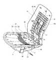
図1は椅子全体の前面側斜視図であり、まず、図1及び図3に基づいて概要を説明する。本実施形態の椅子は事務用のいわゆる回転椅子に適用しており、椅子は、主要要素として、脚装置1(請求項にいう脚に相当)、座受け部2、座3、背もたれ4、背支柱体5、肘掛け装置7を有している。<Outline of First Embodiment>
FIG. 1 is a front perspective view of the entire chair. First, an outline will be described based on FIGS. 1 and 3. The chair of the present embodiment is applied to a so-called rotating chair for office use, and the chair includes, as main elements, a leg device 1 (corresponding to a leg in the claims), a
ガスシリンダより成る脚支柱6は従来から周知の構成の脚装置1の一部を構成するものであり、脚支柱6は、放射状に延びる複数本(一般に5本)の枝足を有する脚本体の中心部に嵌着されている。肘掛け装置7はオプション部品であり、ベース9(後に詳述する)の左右両側に基端部が着脱可能に取付けられて座3の左右両側に立設されたものである。肘掛け装置7は本発明の要部でないため、詳細な説明は省略する。なお、肘掛け装置7を取り外した状態では、着脱可能な樹脂カバー8にてベース9の左右両側の肘掛け取付け部9dが覆われている(図6、図7等参照)。A
座受け部2は、脚支柱6の上端に固定された上向き開放された筐状の座ベース9と、座座ベース9の上端に対して前後スライド自在に取り付けられた座上金具10とを有している(図2、図6、図11、図12等参照)。 The
座3は、座上金具10の上面に取付けられた座アウターシェル11と、座アウターシェル11の上面に取付けられる座インナーシェル12と、座インナーシェル12の上面に取付けられる座クッション体13とを備えている(図2、図9、図10等参照)。座アウターシェル11及び座インナーシェル12はPOM、PP等の合成樹脂材を素材とした射出成形品であるが、金属製または木製であっても良い。
座インナーシェル12は、座前部12aと座後部12bとを有し、座前部12aと座後部12bとの間は座3の左右方向に長い多数のスリット12cを有する。スリット12cは、着座者の体圧が強く作用する部分を中心にして多数形成されている(図8〜図10参照)。なお、図10に示すように、数箇所のスリット12cの下面を跨ぐように、断面上向きU字状の補強部12dが座インナーシェル12の下面側に連設されている。このスリット12cの群により、着座者の体圧によって下向きに伸び変形することが許容されており、その結果、高いフィット性が得られる。
また、座インナーシェル12は、座3に対応して座前部12aと座後部12bとが多数のスリット12cを有する屈曲可能領域を介して連設されているので、座3が屈曲することが許容されている。座3の屈曲の中心線(折り目線)は、おおよそ着座者の尾てい骨が当たる箇所或いはそれより僅かに前のあたりに設定している。なお、座前部12aと座後部12bとはヒンジ(不図示)にて連結された別パーツの構成としても良い。さらに、座後部12bは、後述する背アウターシェル14の基部14bに係合または連結されているので、背アウターシェル14が沈み込みながら後傾するとき、座後部12bのみが下方に沈むように屈曲できる。The seat
Further, the seat
背もたれ4は、背アウターシェル14と、背アウターシェル14の前面に取付けられる背インナーシェル15と、背インナーシェル15の前面に取付けられる背クッション体16とを備えている(図2、図3〜図9、図11、図12等参照)。背アウターシェル14及び背インナーシェル15は、POM、PP等の合成樹脂材を素材とした射出成形品である。背面側部材の一例としての背アウターシェル14は、側面視L字状に形成され、背インナーシェル15を支持する本体部14aと、この本体部14aの下端から前方向に延設される基部14bとからなる。
実施例では、背支柱体5は、側面視L字状に形成された左右一対のパイプ部材17aを有する背支柱17と、該背支柱17の裏面側を覆う着脱可能な背支柱カバー体18とを備えている。なお、別実施例として、背支柱体5を構成する背支柱17と背支柱カバー体18とが、例えば樹脂材やアルミ成形品にて一体的に形成されている形態であっても良い。In the embodiment, the
背支柱体5における一対のパイプ部材17aの基部は、金属製の座ベース9の内面に固定されたベース基板19に溶接などにて固定され、さらに補強金具20を被せてベース基板19に溶接などにて固定されている(図6、図15等参照)。これに加えてねじ止めしても良い。The base portions of the pair of
座ベース9は上向き開口の箱状の形態であり、その後部内面に金属製のベース基板19が溶接によって固着されている。座ベース9の後端は開放されている。座ベース9とベース基板19に固着されたブッシュ21に、脚支柱6の上端を嵌着している。脚支柱6(ガススプリング)のプッシュバルブを操作する昇降レバー22と、背もたれ4をロッキング動作不可状態とロッキング動作可能状態とに切り換える操作レバー23とが、座ベース9の左右両側に突出するように設けられている(図3、図14等参照)。The
座ベース9における左右両側板9aには、前後方向に長い長孔24を設け、この長孔24に樹脂製のブッシュ24aを装着している。この左右両ブッシュ24aを左右に貫通し、且つ前後方向に摺動可能になるように、連結軸25が配置されている(図6、図12、図14、図15等参照)。The left and
座インナーシェル12が上面にてネジ止めされる平板状の座上金具10の後端部の左右両側には、連結軸25に被嵌する取付け孔26が設けられている。また、座上金具10の後端部であって左右方向の中間位置には、後述するロッキングバネ30の後端に嵌合する後部バネ受け体31aを支持するための支持片29が下向きに延設されている(図2、図12、図15等参照)。そして、座ベース9における左右両側板9aの上端に左右外向きの水平片9bを一体に設けて、この水平片9bに、断面コ字状で抱持部が形成された樹脂製のスライダ部材28が外嵌して固定されている。
座上金具10における左右両側の断面コ字状のスライダ装着部27は、スライダ部材28に被嵌して、座上金具10が座ベース9に対して前後摺動可能に構成されている。座ベース9の前面板9cの内面に固定された前部バネ受け体31bには、ロッキングバネ30の前端が嵌合している。このロッキングバネ30の付勢力により、座上金具10、ひいては座3全体を座受け部2に対して椅子の後方に付勢しているものである。The left and right sides of the rear end portion of the flat seat on fitting 10 of the seat
The
座ベース9における左右両側板9aの外側において、背アウターシェル14の下端基部14bの前端に設けられた左右一対の軸受部32と、上記座上金具10における左右一対の取付け孔26とが、連結軸25に対して被嵌している。取付け孔26は左右両側板9aの外側に対して離間した位置に配置され、軸受部32は外側に接近して配置されている(図12、図14、図16参照)。なお、図12、図14では、連結軸25の様子を見せるため、あえて連結軸25に対して座上金具10を外した状態で図示している。 A pair of left and
これらにより、ロッキング動作時の背もたれ4が後傾するとき、座上金具10が前方向に移動する。そして、これらの荷重をロッキングバネ30にて弾性的に支持することになる。 Accordingly, when the
なお、座インナーシェル12の下面側に係合連結された座アウターシェル11にて、座ベース9における左右両側板9aの外側の上部寄り部位と座上金具10の下方とが覆われていると共に、長孔24やブッシュ24aも外側から覆われる。また、座アウターシェル11の後端には、連結軸25の両端部を覆うカバー部33が一体的に形成されている(図7参照)。これにより、連結軸25が座ベース9から軸方向に抜け出さないように構成されている。さらに、座アウターシェル11の後端には、背アウターシェル14の下端基部14bの前端縁に対して上方から適宜寸法だけ重なる段部34が形成されている(図9参照)。Incidentally, in engagement linked seat
座ベース9内に固定された基部受け(不図示)に、ロックアーム34が上下方向に回動可能に装着されている。ロックアーム34の自由端側には、操作レバー23の先端クランク部23aが嵌まる長孔35が形成されている(図6参照)。
操作レバー23の回動操作にて、先端クランク部23aにて長孔35を介してロックアーム34を押し上げて、ロックアーム34の自由端側を上昇させると、当該ロックアーム34の上面に凹み形成されたストッパ係合部34a(図6、図14参照)に連結軸25が嵌まり、この連結軸25の前進動を阻止する。これにより、座上金具10、ひいては座3の前進動を阻止することができると共に背もたれ4の後傾動を阻止し、ロッキング動作不可状態となる。
図6に示すように、ロックアーム34を伏せ姿勢にすると、ストッパ係合部34aが連結軸25から外れ、連結軸25の前進動を許容する。これにより、座上金具10、ひいては座3の前進動を許容することができると共に背もたれ4の沈み込みながらの後傾動を許容し、ロッキング動作可能状態となる。The receiving fixed base in a seating base 9 (notshown), the
When the
As shown in FIG. 6, when the
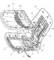
次に、背面側部材の一例としての背アウターシェル14と、背支柱体5との連結構造について説明する。本願発明では、後述するように、開口部40は背面視で縦長に形成され、背もたれ4のノーマル状態及びロッキング状態のいずれの状態においても、背支柱体5にて開口部40が塞がれている。また、背支柱体5に対する背アウターシェル14の装着時には、背支柱体5(特に背支柱カバー体18)の少なくとも上部側が開口部40を介して背アウターシェル14の内面側へ通過し得るように形成されているものである。 Next, a connection structure between the back
例えば、背アウターシェル14の左右中央側における基部14bの前端から本体部14aの上下方向中途高さ位置まで連続して延びるように、開口部40が形成されている。但し、基部14bの前後方向の中途部及び本体部14aの上下方向中途部は、背アウターシェル14の内面側で開口部40を跨ぐように、複数の連結部材41にて一体的に接続されている(図3〜図5、図7、図11、図12、図14参照)。これにより、開口部40で離間された背アウターシェル14の左右部材が不用意に変形しないようになっている。また、開口部40の外周であって、背アウターシェル14の内面には、その剛性を向上させるために、枡目状の多数の補強リブ42が一体的に形成されている。 For example, the
背支柱体5における背支柱17の上端部には背アウターシェル14に対する連結のための横ピン43(請求項にいうピンで固定側連結部に相当)が固定され、横ピン43の左右両端部が外側に露出している。他方、背アウターシェル14における開口部40のうち、本体部14a側にて上下に延びる左右の側縁に沿って、上下長手の左右一対の取付け溝44が互いに向かい合う位置に形成されている。
各取付け溝44には、凹み形成された摺動溝45a(請求項にいう上下長手の溝または孔で可動側連結部に相当)を有するガイド部材45が嵌まる(図2、図4、図6、図8、図9、図11、図12、図14〜図16参照)。実施例では、図示のように、摺動溝45aは上下長手であり、且つ緩やかな円弧状に形成されている。この円弧の中心は背クッション体16側(椅子の手前側)に位置している。A lateral pin 43 (corresponding to afixed-side coupling portion with a pinin the claims) for connection to the back
Each mounting
ガイド部材45は、金属製の横ピン43の両端部との摺動抵抗が少なく、且つ耐摩耗性を有する高機能樹脂製であっても良いし、横ピン43との摺動部にフッ素コーティングを施した金属部材であっても良い。背支柱17に対して背アウターシェル14を装着する際に、ガイド部材45を背アウターシェル14の内面に固定できる構成を採用しても良い。なお、別実施例として、背アウターシェル14に直接、上下長手の摺動溝45aや上下長手の孔を形成しても良いし、逆に、ガイド部材45を背支柱体5側に設け、横ピン43を背アウターシェル14(背面側部材)に設けても良い。The
背支柱17に対して背支柱カバー体18が着脱可能に取付けられている。図13に示すように、背支柱カバー体18の内面には、一対のパイプ部材17aのそれぞれを支持するためのU字状の嵌合溝46aが切欠き形成された支持リブ46が複数個所に形成されている。U字状溝46aの開口端の巾寸法はパイプ部材17aの直径より若干狭く形成されており、その近傍に配置された抜け止め爪47が設けられているため、支持リブ46からパイプ部材17aが容易に脱落しない。また、背支柱カバー体18の左右両側板には、横ピン43の両端部を回避するための切欠き部48が形成されている。さらに、背支柱カバー体18の内面の上部には下向きに開放された筐状の嵌合部49が形成され、背支柱カバー体18の内面の下部には係合爪部50が設けられている。 A back
従って、背支柱17に対して背支柱カバー体18を強固に取り付けるには、図15に示すように、一対のパイプ部材17aの上端どうしを繋ぐ補強ブラケット51の上端に嵌合部49を上方から被嵌する一方、係合爪部50をベース基板19の後端の立ち上げ片に穿設された係合孔(符号無し)に押し込んで係合すれば良い。なお、背支柱17に対して背アウターシェル14を前側から接近させて、開口部40における一対のガイド部材45に対して上記横ピン43の両端部を嵌め入れる。次いで、背アウターシェル14の基部14bにおける軸受部32及び上座金具10の取付け孔26と、座ベース9のブッシュ24の長孔とを位置合わせし、連結軸25をこれらに通して連結する。 Therefore, in order to firmly attach the back
背支柱17に対して背支柱カバー体18を先に取り付けした後、背アウターシェル14を背支柱17に取り付けし(図16参照)、さらにそののち背インナーシェル15を背アウターシェル14に固定する順序が好ましい。背支柱17に対して背支柱カバー体18を後で取り付けしても良い。図4はこの様子を示す。 After the back
ガイド部材45の上端の配置位置は、開口部40の上縁40a(図2〜図4、図7、図15等参照)よりも高い(上)位置に設定されている。 The arrangement position of the upper end of the
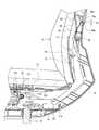
そして、横ピン43がガイド部材45に対して上下動可能な軸連結されていることにより、背もたれ4における背アウターシェル14の内面側(背アウターシェル15との間の空間)が、背支柱体5の上部に対して上下動可能に連結され、背もたれ4のノーマル状態(図2(A)参照)及びロッキング状態(図2(B)参照)のいずれの状態においても、背支柱体5の上部に背アウターシェル14の背面側(本体部14a)が被さっていることになる。従って、横ピン43とガイド部材45による上下動可能な連結部が常時背アウターシェル14にて隠されているから、椅子の背面側の外観が向上するという効果を奏する。
特に、図15に示すように、背もたれ4がノーマル状態において、背支柱体5(背支柱17に背支柱カバー体18が取付けられたもの)の上端18aが、背アウターシェル14の内面側に位置した状態で、開口部40の上縁40aと寸法H1だけ重なり、且つ上端18aが背アウターシェル14の本体部14aの内面に近接した位置にあるため、本体部14aの開口部40(特に上縁40a近傍)に人の指が触れても、当該指が背アウターシェル14と背支柱体5(背支柱カバー体18)との隙間に挟まることがない。勿論人の衣服が上記隙間に挟まることもない。The
In particular, as shown in FIG. 15, when the
背もたれ4のロッキング状態においては、姿勢が一定の背支柱体5に対して背もたれ4が沈み込みながら後傾する。このときも背支柱体5の上部に対して背アウターシェル14の背面側が被さっていることになる(図2(B)参照)。その場合、背支柱体5の上部(背支柱カバー体18の上部)が背アウターシェル14の内面側(背アウターシェル15との間の空間)に大きく入り込むことになるが、開口部40の上縁40aに対して背支柱カバー体18の背面が近接して隙間が生じないように、当該背支柱カバー体18の背面形状を設計するべきである。ロッキング状態とは、背もたれ4が実質的に直立となるノーマル状態から最大後傾姿勢までの途中の後傾姿勢をも含む意味である。 In the rocking state of the
さらに、背もたれ4のノーマル状態(図2(A)参照)及びロッキング状態(図2(B)参照)のいずれの状態においても、開口部40の上下方向に延びる側縁と、背支柱カバー体18の上下方向に延びる側面との間にできる隙間が極力小さくするように設定することが好ましい。背アウターシェル14の背面側に接近または接触した人の衣服などが上記隙間に挟まらないようにするためである。Further, in either the normal state (see FIG. 2A) of the
さらに、背もたれ4のノーマル状態(図2(A)参照)及びロッキング状態(図2(B)参照)のいずれの状態においても、椅子の側面投影視において、背支柱カバー体18の側面の一部と背アウターシェル14の背面とが重なって、両者間に隙間が生じないようにに、背支柱カバー体18及び背アウターシェル14の形状が形成されている。 Furthermore, in any state of the
なお、背アウターシェル14と背インナーシェル15との重ね連結(重ね接合)、及び座アウターシェル11と座インナーシェル12との重ね連結(重ね接合)の構成は、従来から公知の雄型係合部と雌型係合部との嵌め合わせ構造を採用している。また、これらインナーシェルとアウターシェルとの位置合わせ保持のためには、従来から公知の位置ずれの防止手段(ストッパ手段)を用いる。In addition, the structure of the overlap connection (lap joining) of the back
他の実施例として、背クッション体16とその背面側を支持する背面側部材との間の空間内に、背支柱体の上部との上下動可能な連結部が設けられていても良い。 As another embodiment, a connecting portion capable of moving up and down with the upper portion of the back column body may be provided in a space between the
さらに、背面側部材の他の実施例として、背クッション体16の背面を支持する背部材の背面に側面視L字状のフレームが固着されたものがある。このフレームは金属製であっても良い。
すなわち、まず、左右一対の側面視L字状の縦フレーム部とこの縦フレーム部の上端間を繋ぐ上フレーム部とからなる背面矢視で門形のフレームを構成し、この門形のフレームを背部材の左右中央部に固定する。更に、左右一対の縦フレーム部と上フレーム部で囲まれた部位を開口部40とする。そして、左右一対の縦フレーム部の下端基部を座ベース9方向に延設し、その下端基部の前端後述する連結軸25に回動可能に連結する構成とする。かつ、座ベース9に固定された背支柱体5は上記開口部40内に配置され、背支柱体5の上部と左右一対の縦フレーム部の内側上部との間に上下動可能な連結部が設けられた構成とするものである。この構成によっても、背もたれの姿勢の如何に拘らず、背面側部材(=背部材とフレーム)と背支柱体の上部との上下動可能な連結部が常に背面側部材にて隠されていることになる。Furthermore, as another example of the back side member,there is one in which an L-shaped frame in a side view is fixed to the back surface of the back member that supports the back surface of the
That is, first, a gate-shaped frameis formed by a rear arrow view consisting of a pair of leftand right L-shaped vertical frame portions and an upper frame portion connecting the upper ends of the vertical frame portions. Fix to the left and right center of the back member.Further, a portion surrounded by a pair of leftand right vertical frame portions and an upper frame portion is defined as an
1 脚装置
2 座受け部
3 座
4 背もたれ
5 背支柱体
9 座ベース
10 座上金具
11 座アウターシェル
12 座インナーシェル
13 座クッション体
14背面側部材を構成する背アウターシェル
14a 本体部
14b 基部
15 背インナーシェル
16 背クッション体
17背支柱体の背支柱
17a パイプ部材
18背支柱体のの背支柱カバー体
19 座ベース
24 (長い摺動溝を有する)ブッシュ
25 連結軸
30 ロッキングばね
40 開口部
43 横ピン(固定側連結部)
45 ガイド部材
45a 摺動溝(可動側連結部)DESCRIPTION OF SYMBOLS 1
45 Guide member
45a Sliding groove (movable side connecting part)
Claims (4)
Translated fromJapanese前記背もたれにおける背面側部材の内側が、前記背もたれの傾動支点が前後動することを許容しつつ上下動するように前記背支柱体の上部に対して連結部にて連結されており、かつ、前記背もたれの傾動状態及び非傾動状態のいずれの状態においても、前記背支柱体の上部に対して前記背面側部材の背面側が被さっている、
ロッキング椅子。A back column body fixed to a seat receiving portion supported by a leg,and a backrest having a rear side member and freely tiltable in the back direction, and the backresttilts backward whilemoving forward by a tilting fulcrum. A rocking chair,
The inner side of the back side member in the backrest is connected tothe upper portion of theback column body at a connecting portionso as to move up and down while allowing the tilting fulcrum of the backrest to move back and forth, and The back side of the back side member covers the upper part of the back strut body in both thetilted state and the non-tilted state of the backrest,
Russia Kkingu chair.
請求項1に記載のロッキング椅子。Wherein the connection portion between the rear-side member and the back pillar bodyis made up of upperand lower longitudinal grooves or holes andfitted waiting pinsthereto,
The rocking chair according to claim 1.
請求項1または2に記載のロッキング椅子。Wherein the rear-side member is formed vertically long opening in a rear view,that this opening is not blocked by the back pillarbody,
The rocking chair according to claim 1 or 2.
前記背もたれは背面側部材を備えており、前記背もたれの傾動状態及び非傾動状態のいずれの状態においても、前記連結部が前記背面側部材で後ろから覆われている、The backrest includes a back side member, and the connecting portion is covered with the back side member from the back in any of the tilted state and the non-tilted state of the backrest,
ロッキング椅子。Rocking chair.
Priority Applications (8)
| Application Number | Priority Date | Filing Date | Title |
|---|---|---|---|
| JP2009245006AJP5514509B2 (en) | 2009-10-26 | 2009-10-26 | Rocking chair |
| KR1020127010673AKR20120079118A (en) | 2009-10-26 | 2009-11-30 | Rocking chair |
| CN200980162162.2ACN102595972B (en) | 2009-10-26 | 2009-11-30 | Rocking chair |
| US13/503,943US8752896B2 (en) | 2009-10-26 | 2009-11-30 | Rocking chair |
| CA2779060ACA2779060A1 (en) | 2009-10-26 | 2009-11-30 | Rocking chair |
| PCT/JP2009/070128WO2011052099A1 (en) | 2009-10-26 | 2009-11-30 | Rocking chair |
| EP09850877AEP2494887A4 (en) | 2009-10-26 | 2009-11-30 | ROCKING CHAIR |
| PH1/2012/500817APH12012500817A1 (en) | 2009-10-26 | 2009-11-30 | Rocking chair |
Applications Claiming Priority (1)
| Application Number | Priority Date | Filing Date | Title |
|---|---|---|---|
| JP2009245006AJP5514509B2 (en) | 2009-10-26 | 2009-10-26 | Rocking chair |
Publications (2)
| Publication Number | Publication Date |
|---|---|
| JP2011087832A JP2011087832A (en) | 2011-05-06 |
| JP5514509B2true JP5514509B2 (en) | 2014-06-04 |
Family
ID=43921539
Family Applications (1)
| Application Number | Title | Priority Date | Filing Date |
|---|---|---|---|
| JP2009245006AActiveJP5514509B2 (en) | 2009-10-26 | 2009-10-26 | Rocking chair |
Country Status (8)
| Country | Link |
|---|---|
| US (1) | US8752896B2 (en) |
| EP (1) | EP2494887A4 (en) |
| JP (1) | JP5514509B2 (en) |
| KR (1) | KR20120079118A (en) |
| CN (1) | CN102595972B (en) |
| CA (1) | CA2779060A1 (en) |
| PH (1) | PH12012500817A1 (en) |
| WO (1) | WO2011052099A1 (en) |
Families Citing this family (47)
| Publication number | Priority date | Publication date | Assignee | Title |
|---|---|---|---|---|
| WO2011156536A2 (en)* | 2010-06-10 | 2011-12-15 | Office Master | Chair with seat depth adjustment and back support |
| US8602501B2 (en)* | 2010-09-14 | 2013-12-10 | Herman Miller, Inc. | Backrest |
| EP2717742B1 (en)* | 2011-06-09 | 2015-12-16 | Haworth, Inc | Forward sliding reclining chair |
| WO2013020088A2 (en) | 2011-08-04 | 2013-02-07 | Cramer Llc | Ergonomic seating assemblies and methods |
| CN108814056B (en)* | 2012-09-21 | 2021-11-12 | 斯迪尔科斯公司 | Chair component assembly |
| EP2805848B1 (en)* | 2013-05-22 | 2018-09-26 | Fabricacion Asientos Vehiculos Industriales, S.A. | Seat for vehicles |
| CN103479112A (en)* | 2013-09-24 | 2014-01-01 | 浙江永艺家具股份有限公司 | Swivel chair base plate |
| CA2852691A1 (en)* | 2014-05-27 | 2015-11-27 | Keilhauer Ltd. | Seat pan-based spring tilt mechanism |
| US9237811B1 (en)* | 2014-11-03 | 2016-01-19 | Patra Co., Ltd. | Chair with improved waist bearing power |
| DE102015102007B3 (en)* | 2015-02-12 | 2016-07-28 | Wilkhahn Wilkening + Hahne Gmbh + Co. | seating |
| EP3282899B1 (en) | 2015-04-13 | 2021-11-03 | Steelcase Inc. | Seating arrangement |
| US10194750B2 (en) | 2015-04-13 | 2019-02-05 | Steelcase Inc. | Seating arrangement |
| US11259637B2 (en) | 2015-04-13 | 2022-03-01 | Steelcase Inc. | Seating arrangement |
| US10966527B2 (en) | 2017-06-09 | 2021-04-06 | Steelcase Inc. | Seating arrangement and method of construction |
| WO2017003518A1 (en)* | 2015-06-29 | 2017-01-05 | Zodiac Seats Us Llc | Ramp mount |
| CN106983297B (en)* | 2016-01-21 | 2023-08-18 | 浙江润大柯泓家具有限公司 | Chair with seat cushion capable of moving back and forth and backrest capable of being folded |
| CN107788732A (en)* | 2016-09-01 | 2018-03-13 | 永艺家具股份有限公司 | A kind of armchair structure and seat |
| DE202016105769U1 (en)* | 2016-10-14 | 2016-11-10 | Topstar Gmbh | seating |
| DE102016121551A1 (en)* | 2016-11-10 | 2018-05-17 | Bock 1 Gmbh & Co. Kg | Rocking mechanism for a chair |
| US10231546B2 (en)* | 2017-03-02 | 2019-03-19 | Knoll, Inc. | Chair back tilt mechanism |
| USD851417S1 (en) | 2017-05-25 | 2019-06-18 | Steelcase Inc. | Seating arrangement |
| USD851418S1 (en) | 2017-05-25 | 2019-06-18 | Steelcase Inc. | Seating arrangement |
| USD852526S1 (en) | 2017-05-25 | 2019-07-02 | Steelcase Inc. | Seating arrangement |
| USD851952S1 (en) | 2017-05-25 | 2019-06-25 | Steelcase Inc. | Seating arrangement |
| USD852525S1 (en) | 2017-05-25 | 2019-07-02 | Steelcase Inc. | Seating arrangement |
| USD846294S1 (en) | 2017-05-25 | 2019-04-23 | Steelcase Inc. | Seating arrangement |
| USD852524S1 (en) | 2017-05-25 | 2019-07-02 | Steelcase Inc. | Seating arrangement |
| USD827352S1 (en) | 2017-05-25 | 2018-09-04 | Steelcase Inc. | Seating arrangement |
| CN110650657B (en)* | 2017-06-20 | 2023-06-27 | 国誉株式会社 | Chair |
| EP3691497B1 (en)* | 2017-10-05 | 2024-04-24 | Godrej & Boyce Mfg. Co. Ltd. | Posture adaptive work chair |
| CN209073846U (en)* | 2018-05-11 | 2019-07-09 | 杭州中泰实业集团有限公司 | A kind of Revolving chair tray that slider-crank mechanism is adjusted |
| CN209018141U (en)* | 2018-05-11 | 2019-06-25 | 杭州中泰实业集团有限公司 | A kind of adjustable diameter and screw adjusting Revolving chair tray changing torsional spring angle |
| CN108741826B (en)* | 2018-06-08 | 2021-11-05 | 杰克布斯·弗里德里克·唐纳德 | Rocking chair, modular component for use in rocking chair and part for use in modular component |
| CN113507865A (en) | 2019-02-21 | 2021-10-15 | 斯特尔凯斯公司 | Body support assembly and methods for use and assembly thereof |
| DE102019107745A1 (en)* | 2019-03-26 | 2020-10-01 | Bock 1 Gmbh & Co. Kg | Rocking mechanism for a chair, especially an office chair |
| USD907383S1 (en) | 2019-05-31 | 2021-01-12 | Steelcase Inc. | Chair with upholstered back |
| USD907935S1 (en) | 2019-05-31 | 2021-01-19 | Steelcase Inc. | Chair |
| JPWO2020255195A1 (en)* | 2019-06-17 | 2020-12-24 | ||
| TWM589493U (en)* | 2019-09-05 | 2020-01-21 | 林長貞 | Seat composition structure |
| US11357329B2 (en) | 2019-12-13 | 2022-06-14 | Steelcase Inc. | Body support assembly and methods for the use and assembly thereof |
| KR102154696B1 (en)* | 2020-05-07 | 2020-09-10 | (주)베스툴 | Seat assembly and chair having the same |
| JP1703868S (en)* | 2020-07-22 | 2022-01-04 | ||
| CN112535371A (en)* | 2020-09-29 | 2021-03-23 | 厦门新技术集成有限公司 | Plastic steel chair |
| US12369714B2 (en)* | 2020-10-27 | 2025-07-29 | Okamura Corporation | Chair |
| DE102021104004A1 (en)* | 2021-02-19 | 2022-08-25 | Eb-Invent Gmbh | seating furniture |
| DE102021131277A1 (en)* | 2021-11-29 | 2023-06-01 | Bock 1 Gmbh & Co. Kg | Seat support kit for a chair |
| KR102526688B1 (en)* | 2022-10-18 | 2023-04-27 | 이재오 | A close-pressing type sliding sofa chair and a method of assembling the close-pressing-type sliding sofa chair |
Family Cites Families (31)
| Publication number | Priority date | Publication date | Assignee | Title |
|---|---|---|---|---|
| ZA756831B (en)* | 1975-10-29 | 1976-10-27 | Kiang Piao | Tv chair with double pillow case and two-step ottoman |
| NL8103037A (en) | 1981-06-23 | 1983-01-17 | Gispen & Staalmeubel Bv | CHAIR. |
| EP0105955B1 (en)* | 1982-10-13 | 1986-02-26 | Martin Stoll GmbH | Chair |
| DE3617624A1 (en)* | 1986-05-26 | 1987-12-03 | Drabert Soehne | CHAIR |
| DE3724582A1 (en) | 1987-07-24 | 1989-02-02 | Inaba Seisakusho Ltd | A piece of seating furniture |
| EP0303720B1 (en) | 1987-08-14 | 1991-04-10 | Grammer Ag | Seat, in particular a work seat such as an office chair or vehicle seat |
| DE4210282C1 (en) | 1992-03-28 | 1993-04-01 | Martin Stoll Gmbh, 7890 Waldshut-Tiengen, De | |
| US5333368A (en)* | 1992-09-08 | 1994-08-02 | Haworth, Inc. | Chair control with forward tilt |
| JP3378321B2 (en)* | 1993-12-10 | 2003-02-17 | 株式会社イトーキクレビオ | Chair with backrest |
| DE19634665A1 (en) | 1996-08-28 | 1998-03-05 | Jungjohann Thomas | Seating furniture element, in particular upholstered furniture element, with a coupled backrest and seat adjustment |
| DE19752355C2 (en) | 1996-10-14 | 2001-12-06 | Mathieu Ernst Ulrich | Adjustable seat |
| JPH1118867A (en) | 1997-06-30 | 1999-01-26 | Takara Belmont Co Ltd | Chair and its manufacture |
| JPH11113668A (en) | 1997-10-08 | 1999-04-27 | Tokai Kinzoku Kogyo Kk | Chair |
| US5909923A (en)* | 1997-10-24 | 1999-06-08 | Steelcase Inc. | Chair with novel pivot mounts and method of assembly |
| NO982957L (en) | 1998-06-25 | 1999-12-27 | Nils Seiersten | Device by chair, e.g. a recliner |
| JP2000236977A (en) | 1999-02-23 | 2000-09-05 | Plus Property Corp | Tilt device of chair |
| DE10126001A1 (en)* | 2001-05-18 | 2002-11-21 | Bock 1 Gmbh & Co | Preloaded spring arrangement, in particular for spring loading of synchronous mechanisms in office chairs |
| DE10200355A1 (en)* | 2002-01-08 | 2003-07-17 | Dauphin Friedrich W Gmbh | chair |
| JP4137536B2 (en) | 2002-07-03 | 2008-08-20 | コクヨ株式会社 | Chair |
| US6880886B2 (en) | 2002-09-12 | 2005-04-19 | Steelcase Development Corporation | Combined tension and back stop function for seating unit |
| WO2004037047A1 (en) | 2002-10-11 | 2004-05-06 | Kokuyo Furniture Co.,Ltd. | Structure of chair backrest |
| JP4202784B2 (en)* | 2003-02-19 | 2008-12-24 | 株式会社岡村製作所 | Chair backrest device |
| WO2004089162A2 (en)* | 2003-04-02 | 2004-10-21 | Wells Harold G | Articulated seating mechanism |
| US7270371B2 (en)* | 2005-10-27 | 2007-09-18 | Lear Corporation | Truck slouch seat |
| JP4803667B2 (en)* | 2006-07-07 | 2011-10-26 | 株式会社イトーキ | Chair |
| JP4803668B2 (en) | 2006-07-10 | 2011-10-26 | 株式会社イトーキ | Chair |
| CN104305754A (en) | 2007-01-29 | 2015-01-28 | 赫尔曼米勒有限公司 | Seating structure and methods for the use thereof |
| JP5386071B2 (en) | 2007-02-05 | 2014-01-15 | タカノ株式会社 | Chair |
| US7611202B2 (en) | 2007-12-12 | 2009-11-03 | L & P Property Management Company | Tilt mechanism for a chair |
| JP5347141B2 (en) | 2008-01-16 | 2013-11-20 | コクヨ株式会社 | Chair |
| DE102009016968B4 (en)* | 2009-04-14 | 2012-01-26 | Votteler Designpartner Gmbh | seating |
- 2009
- 2009-10-26JPJP2009245006Apatent/JP5514509B2/enactiveActive
- 2009-11-30KRKR1020127010673Apatent/KR20120079118A/ennot_activeWithdrawn
- 2009-11-30CNCN200980162162.2Apatent/CN102595972B/ennot_activeExpired - Fee Related
- 2009-11-30EPEP09850877Apatent/EP2494887A4/ennot_activeWithdrawn
- 2009-11-30PHPH1/2012/500817Apatent/PH12012500817A1/enunknown
- 2009-11-30WOPCT/JP2009/070128patent/WO2011052099A1/enactiveApplication Filing
- 2009-11-30CACA2779060Apatent/CA2779060A1/ennot_activeAbandoned
- 2009-11-30USUS13/503,943patent/US8752896B2/ennot_activeExpired - Fee Related
Also Published As
| Publication number | Publication date |
|---|---|
| EP2494887A4 (en) | 2013-03-13 |
| CN102595972A (en) | 2012-07-18 |
| JP2011087832A (en) | 2011-05-06 |
| WO2011052099A1 (en) | 2011-05-05 |
| EP2494887A1 (en) | 2012-09-05 |
| PH12012500817A1 (en) | 2012-11-26 |
| CA2779060A1 (en) | 2011-05-05 |
| US8752896B2 (en) | 2014-06-17 |
| US20120205952A1 (en) | 2012-08-16 |
| CN102595972B (en) | 2015-12-02 |
| KR20120079118A (en) | 2012-07-11 |
Similar Documents
| Publication | Publication Date | Title |
|---|---|---|
| JP5514509B2 (en) | Rocking chair | |
| KR200426959Y1 (en) | Length adjustment structure of chair seat | |
| KR20130133763A (en) | Chair with armrest | |
| JP2009106422A (en) | Chair | |
| JP6215659B2 (en) | Chair | |
| US10159347B2 (en) | Tilt mechanism for a weight-responsive seating furniture | |
| JP2013132402A (en) | Chair | |
| KR101902770B1 (en) | Assembly and chair with the same | |
| JP2006000143A (en) | Chair with table | |
| JP6287948B2 (en) | Chair | |
| JP5860513B2 (en) | Chair | |
| JP5795142B2 (en) | Rocking chair | |
| JP4520622B2 (en) | Seat mounting device in chair | |
| JP2002136376A (en) | Device for adjusting back and forth directional position of seat | |
| JP7260949B2 (en) | Chair | |
| JP6307042B2 (en) | Chair | |
| JP6358166B2 (en) | Chair | |
| JP7551092B2 (en) | chair | |
| JP6059504B2 (en) | Chair | |
| JP7678715B2 (en) | chair | |
| JP4547019B2 (en) | Seat front / rear sliding device in a chair | |
| JP6731830B2 (en) | Mounting structure of rotation operation member and furniture including the same | |
| JP3810880B2 (en) | Chair | |
| KR102064195B1 (en) | Chair having movable backrest and seat plate | |
| JP6860324B2 (en) | Chair |
Legal Events
| Date | Code | Title | Description |
|---|---|---|---|
| A621 | Written request for application examination | Free format text:JAPANESE INTERMEDIATE CODE: A621 Effective date:20121026 | |
| A131 | Notification of reasons for refusal | Free format text:JAPANESE INTERMEDIATE CODE: A131 Effective date:20131218 | |
| A521 | Request for written amendment filed | Free format text:JAPANESE INTERMEDIATE CODE: A523 Effective date:20140213 | |
| TRDD | Decision of grant or rejection written | ||
| A01 | Written decision to grant a patent or to grant a registration (utility model) | Free format text:JAPANESE INTERMEDIATE CODE: A01 Effective date:20140305 | |
| A61 | First payment of annual fees (during grant procedure) | Free format text:JAPANESE INTERMEDIATE CODE: A61 Effective date:20140331 | |
| R150 | Certificate of patent or registration of utility model | Ref document number:5514509 Country of ref document:JP Free format text:JAPANESE INTERMEDIATE CODE: R150 | |
| S531 | Written request for registration of change of domicile | Free format text:JAPANESE INTERMEDIATE CODE: R313531 | |
| R350 | Written notification of registration of transfer | Free format text:JAPANESE INTERMEDIATE CODE: R350 | |
| R250 | Receipt of annual fees | Free format text:JAPANESE INTERMEDIATE CODE: R250 | |
| R250 | Receipt of annual fees | Free format text:JAPANESE INTERMEDIATE CODE: R250 |