JP5514008B2 - Disposable puncture device - Google Patents
Disposable puncture deviceDownload PDFInfo
- Publication number
- JP5514008B2 JP5514008B2JP2010141526AJP2010141526AJP5514008B2JP 5514008 B2JP5514008 B2JP 5514008B2JP 2010141526 AJP2010141526 AJP 2010141526AJP 2010141526 AJP2010141526 AJP 2010141526AJP 5514008 B2JP5514008 B2JP 5514008B2
- Authority
- JP
- Japan
- Prior art keywords
- lancet
- locking ring
- housing
- locking
- puncture
- Prior art date
- Legal status (The legal status is an assumption and is not a legal conclusion. Google has not performed a legal analysis and makes no representation as to the accuracy of the status listed.)
- Active
Links
- 230000002265preventionEffects0.000claimsdescription49
- 230000007246mechanismEffects0.000claimsdescription27
- 238000006073displacement reactionMethods0.000claimsdescription13
- POIUWJQBRNEFGX-XAMSXPGMSA-NcathelicidinChemical compoundC([C@@H](C(=O)N[C@@H](CCCNC(N)=N)C(=O)N[C@@H](CCCCN)C(=O)N[C@@H](CO)C(=O)N[C@@H](CCCCN)C(=O)N[C@@H](CCC(O)=O)C(=O)N[C@@H](CCCCN)C(=O)N[C@@H]([C@@H](C)CC)C(=O)NCC(=O)N[C@@H](CCCCN)C(=O)N[C@@H](CCC(O)=O)C(=O)N[C@@H](CC=1C=CC=CC=1)C(=O)N[C@@H](CCCCN)C(=O)N[C@@H](CCCNC(N)=N)C(=O)N[C@@H]([C@@H](C)CC)C(=O)N[C@@H](C(C)C)C(=O)N[C@@H](CCC(N)=O)C(=O)N[C@@H](CCCNC(N)=N)C(=O)N[C@@H]([C@@H](C)CC)C(=O)N[C@@H](CCCCN)C(=O)N[C@@H](CC(O)=O)C(=O)N[C@@H](CC=1C=CC=CC=1)C(=O)N[C@@H](CC(C)C)C(=O)N[C@@H](CCCNC(N)=N)C(=O)N[C@@H](CC(N)=O)C(=O)N[C@@H](CC(C)C)C(=O)N[C@@H](C(C)C)C(=O)N1[C@@H](CCC1)C(=O)N[C@@H](CCCNC(N)=N)C(=O)N[C@@H]([C@@H](C)O)C(=O)N[C@@H](CCC(O)=O)C(=O)N[C@@H](CO)C(O)=O)NC(=O)[C@H](CC=1C=CC=CC=1)NC(=O)[C@H](CC(O)=O)NC(=O)CNC(=O)[C@H](CC(C)C)NC(=O)[C@@H](N)CC(C)C)C1=CC=CC=C1POIUWJQBRNEFGX-XAMSXPGMSA-N0.000description22
- 230000006835compressionEffects0.000description22
- 238000007906compressionMethods0.000description22
- 230000002093peripheral effectEffects0.000description19
- 239000008280bloodSubstances0.000description8
- 210000004369bloodAnatomy0.000description8
- 230000000694effectsEffects0.000description8
- 210000000078clawAnatomy0.000description3
- WQZGKKKJIJFFOK-GASJEMHNSA-NGlucoseNatural productsOC[C@H]1OC(O)[C@H](O)[C@@H](O)[C@@H]1OWQZGKKKJIJFFOK-GASJEMHNSA-N0.000description2
- 239000008103glucoseSubstances0.000description2
- 229920005989resinPolymers0.000description2
- 239000011347resinSubstances0.000description2
- 125000002066L-histidyl groupChemical group[H]N1C([H])=NC(C([H])([H])[C@](C(=O)[*])([H])N([H])[H])=C1[H]0.000description1
- OAICVXFJPJFONN-UHFFFAOYSA-NPhosphorusChemical compound[P]OAICVXFJPJFONN-UHFFFAOYSA-N0.000description1
- 230000004913activationEffects0.000description1
- 230000002411adverseEffects0.000description1
- 230000004323axial lengthEffects0.000description1
- 230000000903blocking effectEffects0.000description1
- 238000006243chemical reactionMethods0.000description1
- 206010012601diabetes mellitusDiseases0.000description1
- 230000005489elastic deformationEffects0.000description1
- 208000015181infectious diseaseDiseases0.000description1
- 238000005259measurementMethods0.000description1
- 229910052698phosphorusInorganic materials0.000description1
- 239000011574phosphorusSubstances0.000description1
- 229920003002synthetic resinPolymers0.000description1
- 239000000057synthetic resinSubstances0.000description1
- 238000013519translationMethods0.000description1
- 230000014616translationEffects0.000description1
Images


Classifications
- A—HUMAN NECESSITIES
- A61—MEDICAL OR VETERINARY SCIENCE; HYGIENE
- A61B—DIAGNOSIS; SURGERY; IDENTIFICATION
- A61B5/00—Measuring for diagnostic purposes; Identification of persons
- A61B5/15—Devices for taking samples of blood
- A61B5/151—Devices specially adapted for taking samples of capillary blood, e.g. by lancets, needles or blades
- A61B5/15142—Devices intended for single use, i.e. disposable
- A61B5/15144—Devices intended for single use, i.e. disposable comprising driving means, e.g. a spring, for retracting the piercing unit into the housing
- A—HUMAN NECESSITIES
- A61—MEDICAL OR VETERINARY SCIENCE; HYGIENE
- A61B—DIAGNOSIS; SURGERY; IDENTIFICATION
- A61B5/00—Measuring for diagnostic purposes; Identification of persons
- A61B5/14—Devices for taking samples of blood ; Measuring characteristics of blood in vivo, e.g. gas concentration within the blood, pH-value of blood
- A61B5/1405—Devices for taking blood samples
- A61B5/1411—Devices for taking blood samples by percutaneous method, e.g. by lancet
- A—HUMAN NECESSITIES
- A61—MEDICAL OR VETERINARY SCIENCE; HYGIENE
- A61B—DIAGNOSIS; SURGERY; IDENTIFICATION
- A61B5/00—Measuring for diagnostic purposes; Identification of persons
- A61B5/15—Devices for taking samples of blood
- A61B5/150007—Details
- A61B5/150015—Source of blood
- A61B5/150022—Source of blood for capillary blood or interstitial fluid
- A—HUMAN NECESSITIES
- A61—MEDICAL OR VETERINARY SCIENCE; HYGIENE
- A61B—DIAGNOSIS; SURGERY; IDENTIFICATION
- A61B5/00—Measuring for diagnostic purposes; Identification of persons
- A61B5/15—Devices for taking samples of blood
- A61B5/150007—Details
- A61B5/150374—Details of piercing elements or protective means for preventing accidental injuries by such piercing elements
- A61B5/150381—Design of piercing elements
- A61B5/150412—Pointed piercing elements, e.g. needles, lancets for piercing the skin
- A—HUMAN NECESSITIES
- A61—MEDICAL OR VETERINARY SCIENCE; HYGIENE
- A61B—DIAGNOSIS; SURGERY; IDENTIFICATION
- A61B5/00—Measuring for diagnostic purposes; Identification of persons
- A61B5/15—Devices for taking samples of blood
- A61B5/150007—Details
- A61B5/150374—Details of piercing elements or protective means for preventing accidental injuries by such piercing elements
- A61B5/150381—Design of piercing elements
- A61B5/150503—Single-ended needles
- A61B5/150519—Details of construction of hub, i.e. element used to attach the single-ended needle to a piercing device or sampling device
- A—HUMAN NECESSITIES
- A61—MEDICAL OR VETERINARY SCIENCE; HYGIENE
- A61B—DIAGNOSIS; SURGERY; IDENTIFICATION
- A61B5/00—Measuring for diagnostic purposes; Identification of persons
- A61B5/15—Devices for taking samples of blood
- A61B5/150007—Details
- A61B5/150374—Details of piercing elements or protective means for preventing accidental injuries by such piercing elements
- A61B5/150534—Design of protective means for piercing elements for preventing accidental needle sticks, e.g. shields, caps, protectors, axially extensible sleeves, pivotable protective sleeves
- A61B5/150541—Breakable protectors, e.g. caps, shields or sleeves, i.e. protectors separated destructively, e.g. by breaking a connecting area
- A61B5/150549—Protectors removed by rotational movement, e.g. torsion or screwing
- A—HUMAN NECESSITIES
- A61—MEDICAL OR VETERINARY SCIENCE; HYGIENE
- A61B—DIAGNOSIS; SURGERY; IDENTIFICATION
- A61B5/00—Measuring for diagnostic purposes; Identification of persons
- A61B5/15—Devices for taking samples of blood
- A61B5/150007—Details
- A61B5/150374—Details of piercing elements or protective means for preventing accidental injuries by such piercing elements
- A61B5/150534—Design of protective means for piercing elements for preventing accidental needle sticks, e.g. shields, caps, protectors, axially extensible sleeves, pivotable protective sleeves
- A61B5/15058—Joining techniques used for protective means
- A61B5/150618—Integrally moulded protectors, e.g. protectors simultaneously moulded together with a further component, e.g. a hub, of the piercing element
- A—HUMAN NECESSITIES
- A61—MEDICAL OR VETERINARY SCIENCE; HYGIENE
- A61B—DIAGNOSIS; SURGERY; IDENTIFICATION
- A61B5/00—Measuring for diagnostic purposes; Identification of persons
- A61B5/15—Devices for taking samples of blood
- A61B5/150007—Details
- A61B5/150374—Details of piercing elements or protective means for preventing accidental injuries by such piercing elements
- A61B5/150534—Design of protective means for piercing elements for preventing accidental needle sticks, e.g. shields, caps, protectors, axially extensible sleeves, pivotable protective sleeves
- A61B5/150694—Procedure for removing protection means at the time of piercing
- A61B5/150717—Procedure for removing protection means at the time of piercing manually removed
- A—HUMAN NECESSITIES
- A61—MEDICAL OR VETERINARY SCIENCE; HYGIENE
- A61B—DIAGNOSIS; SURGERY; IDENTIFICATION
- A61B5/00—Measuring for diagnostic purposes; Identification of persons
- A61B5/15—Devices for taking samples of blood
- A61B5/150007—Details
- A61B5/150885—Preventing re-use
- A61B5/150916—Preventing re-use by blocking components, e.g. piston, driving device or fluid passageway
- A—HUMAN NECESSITIES
- A61—MEDICAL OR VETERINARY SCIENCE; HYGIENE
- A61B—DIAGNOSIS; SURGERY; IDENTIFICATION
- A61B5/00—Measuring for diagnostic purposes; Identification of persons
- A61B5/15—Devices for taking samples of blood
- A61B5/151—Devices specially adapted for taking samples of capillary blood, e.g. by lancets, needles or blades
- A61B5/15101—Details
- A61B5/15103—Piercing procedure
- A61B5/15107—Piercing being assisted by a triggering mechanism
- A61B5/15113—Manually triggered, i.e. the triggering requires a deliberate action by the user such as pressing a drive button
- A—HUMAN NECESSITIES
- A61—MEDICAL OR VETERINARY SCIENCE; HYGIENE
- A61B—DIAGNOSIS; SURGERY; IDENTIFICATION
- A61B5/00—Measuring for diagnostic purposes; Identification of persons
- A61B5/15—Devices for taking samples of blood
- A61B5/151—Devices specially adapted for taking samples of capillary blood, e.g. by lancets, needles or blades
- A61B5/15101—Details
- A61B5/15115—Driving means for propelling the piercing element to pierce the skin, e.g. comprising mechanisms based on shape memory alloys, magnetism, solenoids, piezoelectric effect, biased elements, resilient elements, vacuum or compressed fluids
- A61B5/15117—Driving means for propelling the piercing element to pierce the skin, e.g. comprising mechanisms based on shape memory alloys, magnetism, solenoids, piezoelectric effect, biased elements, resilient elements, vacuum or compressed fluids comprising biased elements, resilient elements or a spring, e.g. a helical spring, leaf spring, or elastic strap
- A—HUMAN NECESSITIES
- A61—MEDICAL OR VETERINARY SCIENCE; HYGIENE
- A61B—DIAGNOSIS; SURGERY; IDENTIFICATION
- A61B5/00—Measuring for diagnostic purposes; Identification of persons
- A61B5/15—Devices for taking samples of blood
- A61B5/151—Devices specially adapted for taking samples of capillary blood, e.g. by lancets, needles or blades
- A61B5/15101—Details
- A61B5/15126—Means for controlling the lancing movement, e.g. 2D- or 3D-shaped elements, tooth-shaped elements or sliding guides
- A61B5/1513—Means for controlling the lancing movement, e.g. 2D- or 3D-shaped elements, tooth-shaped elements or sliding guides comprising linear sliding guides
- A—HUMAN NECESSITIES
- A61—MEDICAL OR VETERINARY SCIENCE; HYGIENE
- A61B—DIAGNOSIS; SURGERY; IDENTIFICATION
- A61B5/00—Measuring for diagnostic purposes; Identification of persons
- A61B5/15—Devices for taking samples of blood
- A61B5/151—Devices specially adapted for taking samples of capillary blood, e.g. by lancets, needles or blades
- A61B5/15142—Devices intended for single use, i.e. disposable
Landscapes
- Health & Medical Sciences (AREA)
- Life Sciences & Earth Sciences (AREA)
- Heart & Thoracic Surgery (AREA)
- Medical Informatics (AREA)
- Biophysics (AREA)
- Pathology (AREA)
- Engineering & Computer Science (AREA)
- Biomedical Technology (AREA)
- Hematology (AREA)
- Physics & Mathematics (AREA)
- Molecular Biology (AREA)
- Surgery (AREA)
- Animal Behavior & Ethology (AREA)
- General Health & Medical Sciences (AREA)
- Public Health (AREA)
- Veterinary Medicine (AREA)
- Dermatology (AREA)
- Measurement Of The Respiration, Hearing Ability, Form, And Blood Characteristics Of Living Organisms (AREA)
Description
Translated fromJapanese本発明は、皮膚を穿刺して、少量の血液を採取するために用いられる穿刺器具に係り、特に、1回の使用で廃棄されるディスポーザブル型穿刺器具に関するものである。 The present invention relates to a puncture device that is used to puncture the skin and collect a small amount of blood, and more particularly to a disposable puncture device that is discarded after a single use.
医療目的で、少量の血液を自己採取しなければならない場合がある。例えば、糖尿病患者は、血糖レベルを定期的にチェック(血糖自己測定:SMBG)するために、患者自身が、自己の血液を採取する必要がある。このような血液の自己採取を安全且つ確実に行うことができるように、従来から、穿刺器具が用いられている。特に、感染防止の目的で、1回限りの使用で廃棄されるディスポーザブル型の穿刺器具が提供されている。 For medical purposes, it may be necessary to self-collect a small amount of blood. For example, a diabetic patient needs to collect his / her own blood in order to regularly check the blood glucose level (blood glucose self-measurement: SMBG). Conventionally, a puncture device has been used so that such blood self-collection can be performed safely and reliably. In particular, disposable puncture devices that are discarded after one-time use have been provided for the purpose of preventing infection.
かかる穿刺器具は、一般に、ハウジングに収容されたランセットをばね部材で付勢して、ランセットの先端部に設けた穿刺体をハウジングから突出させて穿刺作動させるようになっている。具体的には、特表2007−521031号公報(特許文献1)に記載されているように、ランセットをハウジング内に係止せしめた状態下で、ハウジングの操作部材を押してランセットより奥方に配したばね部材を圧縮変形させるようになっており、ばね部材の圧縮力が増大して係止が外れた時点でランセットがハウジングから突出して穿刺作動されるようになっている。 Such a puncture device is generally configured such that a lancet accommodated in a housing is urged by a spring member, and a puncture body provided at the tip of the lancet is protruded from the housing to perform a puncture operation. Specifically, as described in JP-T-2007-521031 (Patent Document 1), with the lancet locked in the housing, the operation member of the housing was pushed and arranged behind the lancet. The spring member is compressed and deformed. When the compression force of the spring member increases and the locking is released, the lancet protrudes from the housing and is punctured.
ところが、このような従来構造の穿刺器具では、ランセットのハウジング内への係止が外れるのに必要とされるばね部材の圧縮力を精度良く設定することが難しかった。それ故、ばね部材が充分に圧縮されていないのにランセットの係止が外れて穿刺作動されるために、充分な穿刺力が及ぼされずに血液の滲出量が不足したり、反対に操作部材を強く押してもランセットの係止が外れずに穿刺作動を行い難い場合もあった。 However, in the puncture device having such a conventional structure, it is difficult to accurately set the compression force of the spring member required for releasing the lock of the lancet into the housing. Therefore, since the lancet is released and the puncture operation is performed even though the spring member is not sufficiently compressed, the puncture force is not exerted and the blood exudation amount is insufficient. In some cases, it was difficult to perform the puncture operation without releasing the locking of the lancet even when pressed strongly.
なお、特表2007−536008号公報(特許文献2)や特許第3964457号公報(特許文献3)には、ばね部材を圧縮変形させるための押圧操作部材に係止解除用の当接部を設け、該押圧操作部材が所定位置まで達した際に、かかる当接部が、ハウジングに係止されたランセットの係止片に当接して係止解除する構造が提案されている。しかし、これらの穿刺器具では、ばね部材を圧縮変形させることに加えてランセットの係止片を変形させて係止解除させるために必要な力を、押圧操作部材に及ぼさなければならず、操作力が大きくなってしまうことが避けられなかった。 In Japanese translations of PCT publication No. 2007-536008 (Patent Document 2) and Japanese Patent No. 3964457 (Patent Document 3), a pressing operation member for compressing and deforming a spring member is provided with an abutment portion for unlocking. A structure has been proposed in which, when the pressing operation member reaches a predetermined position, the abutting portion abuts on the locking piece of the lancet locked to the housing to release the locking. However, in these puncture devices, in addition to compressing and deforming the spring member, the force required for deforming and releasing the latching piece of the lancet must be exerted on the pressing operation member. Inevitably increased.
また、国際公開第2005/110225号パンプレット(特許文献4)や米国特許公開第2005/0070945号明細書(特許文献5)には、ランセットのハウジングへの係止片を横方向から押圧することで係止を外して突出作動させる構造も開示されているが、ランセットに設けた係止片に対して横方向からの押圧力が及ぼされることで、ランセットの中心軸がズレて他部材に引っ掛かったり、他部材に押し付けられて突出作動時の摩擦抵抗が大きくなることで、ランセットの突出作動時の動きが阻害されるおそれがあった。 In addition, in International Publication No. 2005/110225 Pamlet (Patent Document 4) and US Patent Publication No. 2005/0070945 (Patent Document 5), a locking piece to the housing of the lancet is pressed from the side. The structure is also disclosed in which the locking is released and the projection is operated.However, when the pressing force from the lateral direction is applied to the locking piece provided on the lancet, the center axis of the lancet is displaced and caught by other members. Or the friction resistance during the protrusion operation is increased by being pressed against the other member, which may impede the movement of the lancet during the protrusion operation.
また一方、特許第3993529号公報(特許文献6)には、ランセットをハウジングに対して周方向に回転可能にして、ハウジング内面に形成した座面に対するランセットの係止を、ランセットの回転作動で解除する構造も開示されているが、ランセットに回転力を及ぼしてランセットを回転させると、ランセットの変形や変位によって係止の解除や突出作動の安定性を充分に確保し難くなるおそれがあり、特にばね部材で付勢された状態でランセットだけを回転させることが難しく、ばね部材にまで変形が及ぼされて付勢作動に悪影響がでるおそれもあった。 On the other hand, in Japanese Patent No. 3993529 (Patent Document 6), the lancet is rotatable in the circumferential direction with respect to the housing, and the locking of the lancet to the seating surface formed on the inner surface of the housing is released by rotating the lancet. Although the structure to be disclosed is also disclosed, if the lancet is rotated by applying a rotational force to the lancet, there is a risk that it will be difficult to ensure sufficient release of locking and stability of the protrusion operation due to deformation or displacement of the lancet. It is difficult to rotate only the lancet while being urged by the spring member, and there is a possibility that the urging operation is adversely affected by deformation of the spring member.
本発明は、上述の事情を背景に為されたものであって、その解決課題は、ばね部材を圧縮した位置にランセットを係止した穿刺準備位置への保持と、係止解除による穿刺作動とを、確実に且つ安定した作動で行わせることが出来る新規な構造のディスポーザブル型穿刺器具を提供することにある。 The present invention has been made in the background of the above-mentioned circumstances, and the problem to be solved is holding the lancet in the compressed position of the spring member at the puncture preparation position, and puncturing operation by releasing the lock. It is an object of the present invention to provide a disposable puncture device having a novel structure that can be reliably and stably operated.
本発明の第1の態様は、ハウジングに収容されたランセットをばね部材で付勢し、該ランセットの先端部に設けた穿刺体を該ハウジングから突出させて穿刺作動させるディスポーザブル型穿刺器具において、前記ハウジング内に係止リングを配設し、前記ランセットが該係止リングを貫通して突出方向に変位可能とすると共に、該ランセットに係止突部を設けて、該係止突部の該係止リングへの係止作用により、前記ばね部材を圧縮変形させて該ランセットが該ハウジングの奥方の穿刺準備位置に保持されるようにする一方、該係止リングを回動させることにより該係止リングへの前記係止突部の係止を解除して該ランセットを前記ばね部材で突出方向に変位させて穿刺作動させる操作部材を設け、且つ、穿刺作動後において、前記係止リングの前記ランセットに対する周方向の相対位置が保たれて、該ランセットの前記係止突部における該係止リングへの係止解除状態が保たれることにより、該係止突部の該係止リングへの再係止が防止されることを特徴とする。According to a first aspect of the present invention, in the disposable puncture device, the lancet accommodated in the housing is urged by a spring member, and the puncture body provided at the distal end of the lancet is projected from the housing to perform the puncture operation. A locking ring is disposed in the housing so that the lancet can be displaced in the protruding direction through the locking ring, and a locking projection is provided on the lancet, and the engagement of the locking projection The spring member is compressed and deformed by the locking action to the locking ring so that the lancet is held in the puncture preparation position at the back of the housing, while the locking ring is rotated to rotate the locking ring. It provided the retaining projection operation member to release the locking is displaced in the protruding direction of the lancet in the spring member to puncture operation of thering, and, after puncturing operation, the locking phosphorus The circumferential relative position of the lancet with respect to the lancet is maintained, and the lock release state of the lock projection of the lancet with respect to the lock ring is maintained. Re-locking to is prevented .
本態様の穿刺器具では、ハウジング及びランセットと別体の係止リングを採用し、この係止リングを回動操作することで、ばね部材で付勢されて穿刺準備位置へ保持させたランセットの係止を解除して穿刺作動させることができる。それ故、穿刺準備位置で予め圧縮されたばね部材により、ランセットに対して安定した付勢力が及ぼされて穿刺作動され得る。また、穿刺作動させるための操作力が、ランセットに対して横方向に及ぼされることが回避されることから、ランセットの中心軸のズレに起因する引っ掛かりや他部材への摩擦力の増大が防止されて安定した穿刺作動が実現される。しかも、回動操作される係止リングは、ばね部材で付勢されたランセットと異なり、それだけを容易に回動させることが出来るから、穿刺作動の操作を容易に且つ安定して行うことが可能となる。 In the puncture device of this aspect, a locking ring that is separate from the housing and the lancet is employed, and the engagement of the lancet that is biased by the spring member and held in the puncture preparation position by rotating this locking ring. The stop can be released and the puncture operation can be performed. Therefore, the spring member compressed in advance at the puncture preparation position can exert a stable urging force on the lancet to perform the puncture operation. In addition, since it is avoided that the operating force for puncturing operation is exerted laterally with respect to the lancet, it is possible to prevent an increase in the frictional force on the other members and the catch due to the deviation of the center axis of the lancet. And stable puncture operation is realized. In addition, unlike the lancet biased by the spring member, the locking ring that is operated to rotate can be easily rotated only so that the puncture operation can be performed easily and stably. It becomes.
本発明の第2の態様は、第1の態様に記載のディスポーザブル型穿刺器具において、前記ランセットに再使用防止突部を設け、前記係止突部の係止が解除されて前記ランセットが穿刺作動された前記係止リングの回動位置において、該ランセットを前記ハウジングの奥方に押し込んで変位させると該再使用防止突部が該係止リングに当接して該係止リングに対する該ランセットの奥方への相対変位が制限されて、該係止突部の該係止リングへの再係止が防止されるものである。According to asecond aspect of the present invention, in the disposable puncture device according to thefirst aspect, the lancet is provided with a reuse prevention protrusion, and the lancet is punctured by releasing the lock of the lock protrusion. When the lancet is pushed into the rear of the housing and displaced at the pivoted position of the locking ring, the reuse prevention projection comes into contact with the locking ring and moves toward the back of the lancet with respect to the locking ring. The relative displacement of the locking protrusion is limited, and the locking protrusion is prevented from being re-locked to the locking ring.
本態様の穿刺器具によれば、再使用防止の機構が係止リングを利用して実現され得る。特に、穿刺作動に際して係止リングが回動変位されることを利用して、穿刺作動後の係止リングの回動位置で係止リングに当接する再使用防止突部をランセットに設けたことにより、少ない部品点数と簡単な構造で再使用を確実に防止する機構を実現し得た。 According to the puncture device of this aspect, a reuse prevention mechanism can be realized using the locking ring. In particular, by utilizing the fact that the locking ring is rotationally displaced during the puncturing operation, the lancet is provided with a reuse prevention protrusion that contacts the locking ring at the rotational position of the locking ring after the puncturing operation. Therefore, a mechanism that reliably prevents reuse can be realized with a small number of parts and a simple structure.
本発明の第3の態様は、第2の態様に記載のディスポーザブル型穿刺器具において、前記係止リングが前記ハウジングの奥方への変位を許容されており、前記ランセットが穿刺作動された該係止リングの回動位置において、該ランセットを該ハウジングの奥方に押し込んで変位させると、前記再使用防止突部が該係止リングに当接して該ランセットと共に該係止リングも奥方に変位するものである。According to athird aspect of the present invention, in the disposable puncture device according to thesecond aspect, the locking ring is allowed to be displaced inward of the housing, and the lancet is punctured. When the lancet is pushed into the housing and displaced in the rotational position of the ring, the reuse preventing projection comes into contact with the locking ring, and the locking ring is also displaced in the back together with the lancet. is there.
本態様の穿刺器具によれば、ハウジングの先端側からランセットを押し込むことにより、ランセットの係止突部を強制的に係止リングの奥方まで移動させて係止リングに係止させようとしても、係止リングがランセットと共に奥方に変位してしまうことから、再使用が一層確実に防止され得る。 According to the puncture device of this aspect, even if the lancet is pushed from the distal end side of the housing, the locking projection of the lancet is forcibly moved to the back of the locking ring and locked to the locking ring. Since the locking ring is displaced rearward together with the lancet, reuse can be prevented more reliably.
本発明の第4の態様は、第1〜3の何れか1態様に記載のディスポーザブル型穿刺器具において、前記係止リングの前記ハウジングに対する回動を阻止する誤操作防止機構を設けたものである。According to afourth aspect of the present invention, the disposable puncture device according to any one of the first tothird aspects is provided with an erroneous operation preventing mechanism that prevents the locking ring from rotating relative to the housing.
本態様の穿刺器具においては、係止リングの回動を阻止することで予期しない穿刺作動を防止できるのであり、例えばばね手段で付勢されたランセットの突出を直接に阻止する場合に比して、周方向に付勢されていない係止リングの回動阻止は強度の小さな部材で簡単に実現可能である。 In the puncture device of this aspect, an unexpected puncture operation can be prevented by preventing the rotation of the locking ring. For example, as compared with the case of directly preventing the protrusion of the lancet biased by the spring means. The rotation prevention of the locking ring which is not biased in the circumferential direction can be easily realized with a member having a low strength.
本発明の第5の態様は、第4の態様に記載のディスポーザブル型穿刺器具において、前記ランセットの先端部に装着されて前記穿刺体を覆うキャップが設けられており、該キャップの装着状態下で該キャップと該ランセットとの何れかを介して前記係止リングが前記ハウジングに対して回転不能に係合されて前記誤操作防止機構が構成されていると共に、該キャップを取り外すことでかかる係合が解除されて該係止リングの回動が許容されるものである。According to afifth aspect of the present invention, in the disposable puncture device according to thefourth aspect, a cap is provided to be attached to the tip of the lancet so as to cover the puncture body. together with the locking ring via one of the said cap and said lancetoperation prevention mechanism nonrotatably engaged the erroneously is configured relative to the housing, engagement according by removing the cap Is released and the locking ring is allowed to rotate.
本態様の穿刺器具では、穿刺作動に際して取り外されるキャップを利用して、誤操作防止機構が解除されることから、誤操作防止機構が不用意に解除されてしまうことが防止されると共に、穿刺作動時には特別な操作を必要とすることなく誤操作防止機構が解除され得る。The puncture device of the present embodiment, by utilizing the cap is removed during puncture operation, since the erroneousoperation prevention mechanism is released, along with the erroneousoperation prevention mechanism from being released inadvertently is prevented, the puncture operation erroneousoperation prevention mechanism may be released without sometimes requiring a special operation.
本発明の第6の態様は、第1〜5の何れか1態様に記載のディスポーザブル型穿刺器具において、前記ランセットを前記ハウジングに対して周方向変位を規制しつつ突出方向に案内する案内機構が設けられているものである。According to asixth aspect of the present invention, there is provided the disposable puncture device according to any one of the first tofifth aspects, wherein a guide mechanism that guides the lancet in a protruding direction while restricting circumferential displacement with respect to the housing. It is provided.
本態様の穿刺器具では、係止リングの回動に伴ってランセットが連れ回りしてしまうことが確実に防止されて、係止リングの回動操作による穿刺作動が一層確実に行われ得ると共に、ランセットの突出による穿刺作動の安定性の更なる向上も図られ得る。 In the puncture device of this aspect, the lancet can be reliably prevented from rotating with the rotation of the locking ring, and the puncturing operation by the rotation operation of the locking ring can be performed more reliably, The stability of the puncture operation by the protrusion of the lancet can be further improved.
本発明によれば、係止リングを回動操作することで、ばね部材で付勢されて穿刺準備位置へ保持させたランセットの係止を解除して穿刺作動させることができるから、穿刺作動させるための操作力がランセットに対して横方向に及ぼされることがなく、ランセットの中心軸のズレに起因する引っ掛かりや他部材への摩擦力の増大が防止されて、目的とする穿刺作動が安定して実現され得る。 According to the present invention, the puncture operation can be performed by rotating the locking ring so that the lancet that is biased by the spring member and released to the puncture preparation position can be unlocked and operated. Operation force is not exerted laterally with respect to the lancet, and the target puncture operation is stabilized by preventing an increase in the frictional force to the other members and the catch due to the deviation of the center axis of the lancet. Can be realized.
以下、本発明を更に具体的に明らかにするために、本発明の実施形態について、図面を参照しつつ、詳細に説明する。 Hereinafter, in order to clarify the present invention more specifically, embodiments of the present invention will be described in detail with reference to the drawings.
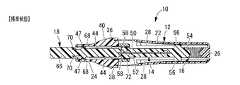
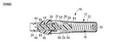
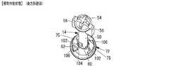
先ず、図1には、本発明の一実施形態としてのディスポーザブル型穿刺器具10の平面図が示されており、その分解斜視図、縦断面図及び横断面図が、図2〜5に示されている。なお、図1,3,4,5は、何れも、市場でユーザーに商品として提供される状態(標準状態)での穿刺器具10を示している。かかる穿刺器具10は、ハウジング12に対して、ランセット14と圧縮コイルばね(ばね部材)16が収容されており、ランセット14から針キャップ18を外してハウジング12の操作片20を押操作することで、ランセット14がハウジング12から突出して穿刺作動するようになっている。なお、以下の説明中、特に断りのない限り、中心軸方向とはハウジング12及びランセット14の中心軸方向(図1中の左右方向)をいい、ランセットの14の突出方向となる図1中の左方向を前方、右方向を後方という。 First, FIG. 1 shows a plan view of a
より詳細には、ハウジング10は、何れも樹脂成形品からなるハウジング本体22とハウジング口体24によって構成されている。ハウジング本体22は、深底の略有底円筒形状とされており、その開口部分に対して略円筒形状のハウジング口体24が固定的に組み付けられている。 More specifically, the
ハウジング本体22の底壁には、内面中央から内方に突出するばね座26が設けられている。また、ハウジング本体22の筒壁には、内周面上に突出して軸方向に直線的に延びる複数本の案内突条28が設けられている。そして、これら複数本の案内突条28により、ハウジング本体22の筒壁内面において、軸直角方向で対向位置する一対のガイドレール30,30が形成されている。 A
また、ハウジング本体22の筒壁には、底壁側部分よりも僅かに拡径された開口側部分に位置して、操作部材としての操作片20が形成されている。この操作片20は、ハウジング本体22の周壁に形成された貫通窓34内に配されて、ハウジング本体22に対して部分的に連結されている。そして、ハウジング本体22の外側から操作片20を手指で押すことにより、かかる連結部の弾性変形に基づいて、操作片20がハウジング本体22の内方に向けて変位されるようになっている。 Further, an
さらに、ハウジング本体22の筒壁の開口周縁部には、外周面上に突出して周方向に延びる係合リブ36が一体形成されている。一方、ハウジング口体24の軸方向後端側には、外周を周方向に延びる大径の係合リング38が一体形成されている。なお、係合リング38は、ハウジング口体24の外周面上で周上の複数箇所に突設された連結脚部40によって、ハウジング口体24に連結支持されている。 Furthermore, an engaging
そして、ハウジング本体22の開口部分にハウジング口体24が組み合わされ、ハウジング口体24の係合リング38に対してハウジング本体22の係合リブ36が係合されることで、ハウジング本体22にハウジング口体24が組み付けられている。なお、かかる組付状態下では、係合リブ36の係合リング38に対する係合作用で、ハウジング本体22に対してハウジング口体24が軸方向に位置決め固定されていると共に、係合リブ36の連結脚部40への係合作用でハウジング本体22に対してハウジング口体24が周方向でも位置決め固定されている。 The
また、ハウジング口体24は、係合リング38の内周側で中心軸上を後方に向かって筒状に延び出しており、それによって、ハウジング本体22内に入り込む支持筒部42が形成されている。また、ハウジング口体24の外周面上に突設された連結脚部40は、支持筒部42の外周面上にまで軸方向に所定長さで延び出して形成されている。更にまた、ハウジング口体24の内周面には、前方側の開口部近くに位置する、一対のキャップ係止用突起47,47が、軸直角方向で対向位置して突出形成されている。 Further, the
さらに、ハウジング口体24の内周面には、一対の第一案内溝44,44と、一対の第二案内溝46,46とが、それぞれ径方向で対向位置して軸方向に平行に延びて形成されている。これら第一案内溝44,44と第二案内溝46,46は、何れも、ハウジング口体24の軸方向中間部分から支持筒部42の内周面にまで延びており、支持筒部42の後方端部に開口されている。 Further, on the inner peripheral surface of the
特に本実施形態では、一対の第一案内溝44,44が対向する径方向と、一対の第二案内溝46,46が対向する径方向とが、互いに直交している。また、第一案内溝44は、第二案内溝46に比して、その周方向幅寸法と径方向深さ寸法とが、何れも大きくされており、支持筒部42では、第一案内溝44が支持筒部42の周壁を貫通してスリット形状とされている。 In particular, in the present embodiment, the radial direction in which the pair of
そして、このようにハウジング本体22とハウジング口体24から構成されたハウジング12には、その内部空間に対してランセット14が収容状態で組み込まれている。なお、ハウジング口体24は、穿刺後の血液溜まりを目視可能とするために透明または半透明とすることが好適である。 In the
かかるランセット14は、インサート成形品であって、ロッド形状を有する合成樹脂製のランセットハブ50に対して、その中心軸上に穿刺針52が埋設固着されている。そして、ランセットハブ50の先端部中央から前方に向かって穿刺針52の先端が突設されている。 The
また、ランセットハブ50の後端部には、周方向に延びる環状支持突部を備えたばね座54が形成されている。更に、ランセットハブ50の後端部分の外周面上には、軸直角方向両側に突出する一対のガイド突起56,56が、一体形成されている。一方、ランセットハブ50の前端部分の外周面上には、軸直角方向両側に突出する一対の再使用防止突部58,58が一体形成されている。更に、かかる一対の再使用防止突部58,58よりも所定寸法だけ軸方向後方に位置して、ランセットハブ50の外周面上で軸直角方向両側に突出する一対の係止突部60,60が一体形成されている。 A
ここにおいて、一対の再使用防止突部58,58の突出方向と、一対の係止突部60,60の突出方向とは、互いに異ならされている。特に本実施形態では、一対の再使用防止突部58,58の突出方向と、一対の係止突部60,60の突出方向とが、互いに中心軸回りで90度異ならされており、また、一対の再使用防止突部58,58の突出方向が、一対のガイド突起56,56の突出方向と、中心軸回りで同じ方向に設定されている。 Here, the protruding direction of the pair of
さらに、ランセットハブ50の先端側には、針キャップ18が設けられている。この針キャップ18は、ロッド形状とされており、穿刺針52が突設されたランセットハブ50の先端から同一中心軸上に延び出して一体成形されている。ランセットハブ50と針キャップ18との境界部分は括れ状に外径寸法が小さくされたねじ切部64とされており、ランセットハブ50に対して針キャップ18を中心軸回りに捩じってねじ切部64で離脱させることで、針キャップ18を手作業でランセットハブ50から取り外すことが出来るようになっている。そして、針キャップ18をランセットハブ50から取り外すことで、針キャップ18で覆われていた穿刺針52の先端部を露出させ得るようになっている。 Further, a
また、図6に示されているように、針キャップ18の先端部分は、扁平な摘み部66とされており、この摘み部66の後端部分には、幅方向両側部分において、それぞれ、突起68と舌片状の弾性爪部70とが軸方向で対向位置して突出形成されている。 Further, as shown in FIG. 6, the tip portion of the
そして、かかるランセット14は、ハウジング本体22に対してランセットハブ50の後端側が差し入れられ、ハウジング口体24に対して針キャップ18が挿通された状態で、ハウジング12の中心軸上に配設されて組み付けられている。また、かかるランセット14のハウジング12への組み付けに際しては、圧縮コイルばね16と係止リング72とがハウジング12内に組み付けられて装着されている。 The
すなわち、圧縮コイルばね16は、ハウジング本体22の底部に収容されて中心軸上に配されており、その後方端部がハウジング本体22のばね座26に嵌められて位置決めされていると共に、その前方端部がランセットハブ50のばね座54に嵌め合わされている。これにより、かかる圧縮コイルばね16が、ハウジング本体22の底部とランセットハブ50の後端部との軸方向対向面間に介装されており、ランセットハブ50が軸方向後方(ハウジング本体22の奥方)に変位されることで圧縮変形させられ、圧縮変形に伴う付勢力がランセットハブ50をハウジング本体22から前方に押し出す方向に及ぼされるようになっている。 That is, the
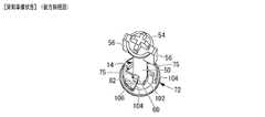
一方、係止リング72は、図6〜9にも示されているように、略円形のリング形状を有する樹脂成形品であり、ハウジング口体24の支持筒部42に外挿されて回動可能に装着されている。なお、係止リング72には、前方に向かって突出する一対の当接脚部74,74が一体形成されており、かかる当接脚部74が、支持筒部42において周上で隣り合う連結脚部40,40間に差し入れられている。そして、係止リング72が回動した際、当接脚部74が連結脚部40に対して周方向で当接することにより、支持筒部42上での係止リング72の周方向の回動許容範囲が45度よりも小さく設定されている。 On the other hand, as shown in FIGS. 6 to 9, the locking
また、係止リング72には、後方端部に位置して内フランジ状の係合部75が一体形成されており、この係合部75の内周面には、一対の第一通過溝76,76と、一対の第二通過溝78,78とが、それぞれ径方向で対向位置して軸方向に平行に延びて形成されている。これら第一通過溝76,76と第二通過溝78,78は、何れも、係合部75の軸方向全長に亘って直線的に延びている。 Further, an engaging
更にまた、係合部75の内径寸法は、ランセットハブ50及び針キャップ18の外径寸法よりも僅かに大きくされており、それらランセットハブ50及び針キャップ18に対して係止リング72が外挿装着されている。また、係合部75の第一通過溝76は、ランセットハブ50の再使用防止突部58よりも僅かに大きな断面形状とされており、かかる再使用防止突部58が第一通過溝76内を軸方向に移動可能とされている。また一方、係合部75の第二通過溝78は、ランセットハブ50の係止突部60よりも僅かに大きな断面形状とされており、かかる係止突部60が第二通過溝78内を軸方向に移動可能とされている。 Furthermore, the inner diameter of the engaging
また、係止リング72では、一対の第一通過溝76,76が対向する径方向と一対の第二通過溝78,78が対向する径方向との為す角度(交角)が、ランセットハブ50において一対の再使用防止突部58,58が対向する径方向と一対の係止突部60,60が対向する径方向との為す角度(交角)と異ならされている。特に本実施形態では、一対の第一通過溝76,76が対向する径方向と一対の第二通過溝78,78が対向する径方向とが、相互に略60度で交差するようにされている。 Further, in the locking
これにより、図8,9からも明らかなように、係止リング72に対してランセットハブ50が挿通された状態下で、ランセットハブ50の一対の再使用防止突部58,58が係止リング72の一対の第一通過溝76,76に位置合わせされて軸方向への通過が許容された周方向の相対位置では、ランセットハブ50の一対の係止突部60,60が係止リング72の一対の第二通過溝78,78に対して位置ずれ状態にあり、係止突部60,60が係止リング72に係止されて軸方向前方への移動が阻止されるようになっている。一方、ランセットハブ50の一対の係止突部60,60が係止リング72の一対の第二通過溝78,78に位置合わせされて軸方向への通過が許容された状態下では、ランセットハブ50の一対の再使用防止突部58,58が係止リング72の一対の第一通過溝76,76に対して位置ずれ状態にあり、再使用防止突部58,58が係止リング72に係止されて係止リング72に対するランセットハブ50の軸方向後方への相対移動が阻止されるようになっている。 As a result, as apparent from FIGS. 8 and 9, the pair of
なお、ランセットハブ50における一対の再使用防止突部58,58と一対の係止突部60,60とは、中心軸方向で係止リング72における係合部75の厚さ寸法より僅かに大きな距離だけ離れている。これにより、係合部75の軸方向前方に再使用防止突部58,58が外れて位置し且つ係合部75の軸方向後方に係止突部60,60が外れて位置した状態下、ランセットハブ50に外挿された係止リング72をランセットハブ50に対して回動させることができるようになっている。そして、この係止リング72の回動により、一対の再使用防止突部58,58と一対の係止突部60,60との何れか一方を、選択的に、第一通過溝76,76または第二通過溝78,78に対して位置合わせして、軸方向への通過変位を許容し得るようになっている。 The pair of
また、係止リング72の外周面には、一対の押圧片80,80が、径方向両側に突出して一体形成されている。この押圧片80は、係止リング72の軸方向視において不等辺直角三角形状を有しており、その斜辺に相当する面が、係止リング72の中心軸回りで傾斜した押圧傾斜面82とされている。そして、図3及び図5に示されているように、これらの押圧片80,80は、係止リング72を支持筒部42に装着した状態下で、ハウジング本体12の操作部20の内方に位置するように位置合わせされている。 In addition, a pair of
このようにして、圧縮コイルばね16及び係止リング72と共にランセット14をハウジング12に組み込むことによって、本実施形態の穿刺器具10が構成されている。なお、ハウジング12に組み込まれたランセット14は、ランセットハブ50に突設されたガイド突起56,56が、ランセット14を突出方向に案内する案内機構としてのガイドレール30,30に差し入れられており、ランセット14のハウジング12に対する周方向変位である中心軸回りの回転を阻止された状態で軸方向の移動が許容されている。 Thus, the
また、ユーザーに提供される商品としての標準状態では、図4に示されているとおり、ハウジング口体24のキャップ係止用突起47,47が、それぞれ、針キャップ18に形成された突起68と弾性爪部70の間で軸方向に挟まれて係止されており、針キャップ18の摘み部66がハウジング口体24から外方に所定長さで突出する状態で、ランセット14がハウジング12に対して軸方向で位置決めされている。 In the standard state as a product provided to the user, as shown in FIG. 4, the
かかる標準状態では、図3に示されているとおり、ランセット14は、圧縮コイルばね16を圧縮変形させて、ランセットハブ50の係止突部60,60が係止リング72よりも更に後方に位置するまで、ハウジング本体22の奥方まで押し込まれている。そして、かかる状態下、図4に示されているように、ランセットハブ50の再使用防止突部58,58は、係止リング72の第一通過溝76,76と、ハウジング口体24の支持筒部42の第一案内溝44,44との間に跨がって位置されている。即ち、係止リング72の第一通過溝76とハウジング口体24の第一案内溝44とが、再使用防止突部58で係合されることによって、係止リング72がハウジング口体24に対して周方向で相対回転不能に係合されて誤操作防止機構が構成されている。 In such a standard state, as shown in FIG. 3, the
また、この位置決め状態下、図5に示されているように、係止リング72の押圧片80の押圧傾斜面82が、操作部20の内方に対向位置している。そして、操作部20を手指でハウジング12内に押し込むことで、操作部20の周方向一方の端部が押圧傾斜面82に押し付けられ、押圧傾斜面82の傾斜角度に応じて発揮される分力作用に基づいて、操作部20の押圧力が係止リング72に対して回転力に変換されて及ぼされるようになっている。尤も、図3,4に示された標準状態では、前述のとおり係止リング72のハウジング12に対する回転が阻止されていることから、操作部20を誤って押圧しても、穿刺器具10が予期せずに穿刺作動することはない。 Further, under this positioning state, as shown in FIG. 5, the pressing
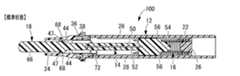
[穿刺準備状態]
次に、上述の如き標準状態で提供された穿刺器具10を用いて穿刺作動させる操作を説明するが、それには先ず、図3,4に示された標準状態の穿刺器具10において、そのハウジング12を片手で把持し、他方の手で針キャップ18を摘まみ、針キャップ18を回転させる。これにより、針キャップ18の突起68と弾性爪部70を、ハウジング口体24のキャップ係止用突起47から離脱させると共に、ランセットハブ50から針キャップ18をねじ切部64でねじ切って、針キャップ18をハウジング口体24から抜き取る。このような操作により、穿刺器具10が、標準状態から、図10,11に示されている穿刺準備状態とされる。[Puncture preparation state]
Next, an operation for performing a puncturing operation using the
この穿刺準備状態とされた穿刺器具10では、針キャップ18のハウジング口体24への軸方向の位置決めが解除されたことで、ランセットハブ50が、圧縮コイルばね16の付勢力で軸方向前方に移動させられる。そして、ランセットハブ50の係止突部60が、係止リング72の係合部75の後端面に当接して軸方向前方への変位が阻止されることとなる。この係止突部60の係止リング72への係止作用により、ランセット14が穿刺準備位置に保持されることとなる。 In the
また、この位置までランセットハブ50が前方に移動されることで、ランセットハブ50の再使用防止突部58,58は、係止リング72の第一通過溝76,76への係合位置から前方に外れて、ハウジング口体24の第一案内溝44,44だけに係合して位置させられる。 Further, when the
このように、穿刺準備状態では、ランセットハブ50の再使用防止突部58,58と係止突部60,60が、係止リング72の第一通過溝76,76と第二通過溝78,78に対して、軸方向前方及び後方にそれぞれ外れて非係合状態とされていることにより、ハウジング12内において係止リング72の回転が許容されている。 Thus, in the puncture preparation state, the
[穿刺作動状態]
それ故、穿刺準備状態から穿刺作動させて穿刺作動状態とするには、図12に示されているように、穿刺準備状態にある穿刺器具10を把持して操作部20を手指で押し込めば良い。操作部20を押し込んで係止リング72の押圧傾斜面82に押し付けることで、係止リング72が中心軸回りでハウジング12及びランセット14に対して回転する。そして、図13,14に示されているように、係止リング72の後端面に当接されていたランセットハブ50の係止突部60,60に対して、係止リング72の第二通過溝78,78が位置合わせされると、係止突部60,60の係止リング72による軸方向の変位阻止力が解除され、係止突部60,60が係止リング72の第二通過溝78,78を通って軸方向前方への変位が許容される。[Puncture activation state]
Therefore, in order to change the puncture operation state from the puncture preparation state to the puncture operation state, as shown in FIG. 12, it is only necessary to hold the
その結果、図15,16に示されているように、ランセット14が圧縮コイルばね16の付勢力に基づいてハウジング12内を軸方向前方に勢い良く移動する。そして、ランセット14のガイド突起56,56が係止リング72の後端面に当接するまでランセット14が軸方向前方に移動することで、ランセット14の先端の穿刺針52が、ハウジング口体24の先端開口部から外方に所定長さで突出して、穿刺作動が実現されるのである。 As a result, as shown in FIGS. 15 and 16, the
[穿刺後]
なお、上述の穿刺作動に際しては、圧縮コイルばね16の付勢力によって圧縮コイルばね16の自由長を超えてランセット14が軸方向前方に移動する。その際、圧縮コイルばね16の軸方向両端部は、ハウジング本体22の底部とランセット14の後端部とにそれぞれ固着されていることから、穿刺針52がハウジング口体24から突出した穿刺時において、ランセット14に対して圧縮コイルばね16の復元力がハウジング12内に引き戻す方向に及ぼされる。[After puncture]
In the above puncturing operation, the
その結果、ハウジング口体24から穿刺針52が突出する穿刺作動が瞬間的に行われ、穿刺後には、図17,18に示されているように、速やかにランセット14がハウジング12内に引き戻されて穿刺針52の針先がハウジング口体24内に収納されることとなる。 As a result, the puncture operation in which the
[再使用防止]
また、上述の如き穿刺後には、図17,18に示されているようにランセット14が、自由長とされた圧縮コイルばね16で位置決めされた軸方向位置に保持されることとなる。また、操作部20で回動された係止リング72も、図13,14に示されている如き回動後の位置のままとされる。即ち、穿刺後には係止リング72に回転力が及ぼされずに係止解除状態とされた回動位置に保たれていることから、ランセット14が押し込まれても、係止突部60は第二通過溝78内を移動するだけであり、係止突部60が係止リング72に対して係止されない。それ故、穿刺後に、たとえ操作部20を操作してもランセット14が軸方向前方に突出する穿刺作動は再現されない。[Reuse prevention]
After puncturing as described above, the
加えて、穿刺後に、ハウジング12の前方開口部から線材等を差し入れてランセット14をハウジング12の奥方に押し込むことで強制的に再使用を試みた場合でも、図13,14に示されているように、ランセット14における再使用防止突部58,58と係止突部60,60との周方向の相対位置が、係止リング72における第一通過溝76,76と第二通過溝78,78との周方向の相対位置に比して、異ならされていることから、再使用がより確実に防止され得る。 In addition, even after a puncture, even if a wire rod or the like is inserted from the front opening of the
すなわち、ハウジング12の奥方にランセット14を強制的に押し込むに際して、たとえランセット14の係止突部60,60を第二通過溝78,78に対して周方向で位置合わせすることが出来て、係止突部60,60を係止リング72より奥方まで移動させ得たとしても、その時点で、既に、再使用防止突部58,58が第一通過溝76,76に対して位置ずれしている。それ故、図19,20に示されているように、そこから更にランセット14を押し込むと、再使用防止突部58,58が係止リング72の係合部75の前端面に当接して、係止リング72もランセット14と一緒にハウジング12の奥方に移動するだけで、係止リング72に対してランセット14を再び係止させて図8〜11に示されている如き穿刺準備状態とすることが実質的に不可能である。 That is, when the
特に本実施形態では、係止リング72が、ハウジング口体24の奥方向に位置して、ハウジング口体24の支持筒部42より大径とされて該支持筒部42に外挿配置されている。それ故、ハウジング口体24の前方開口部から覗き込んでも、係止リング72を視認することが殆ど出来ず、従って、ハウジング口体24の小さな前方開口部を通じて、ランセット14を押し込みつつ同時に係止リング72を回転変位させることなど、実質的に不可能である。 In particular, in the present embodiment, the locking
また、ランセット14は、ガイド突起56,56のガイドレール30,30への係合作用で、ハウジング12に対する中心軸回りの回転が阻止されていることから、ランセット14を回転させて係止リング72に相対回転作用を及ぼすこともできない。ましてや、上述のとおり、係止リング72は、ハウジング本体22の奥方への移動が許容されていることから、ハウジング口体24の前方開口部から差し入れた線材等で係止リング72を回転させようとしても、線材等の係止リング72に対する軸方向の当接反力を得ることさえ困難である。 Further, since the
以上、本発明の実施形態について詳述したが、本発明は、その具体的な記載によって限定されるものではない。例えば、別構造の係止リングを採用したディスポーザブル型穿刺器具を、図21〜34において、本発明の第2の実施形態として例示する。なお、本実施形態のディスポーザブル型穿刺器具100において、第1の実施形態と同様な構造とされた部材及び部位については、それぞれ、図中に第1の実施形態と同じ符合を付することにより、それらの詳細な説明を省略する。 As mentioned above, although embodiment of this invention was explained in full detail, this invention is not limited by the specific description. For example, a disposable puncture device that employs another locking ring structure is illustrated in FIGS. 21 to 34 as the second embodiment of the present invention. In addition, in the
本実施形態の穿刺器具100は、その分解図が図24に示されていると共に、市場でユーザーに商品として提供される標準状態が図21〜23に示されているように、第1の実施形態に比して、ランセットハブ50に突設された一対の再使用防止突部(58,58)を備えていない。なお、本実施形態では、第1の実施形態における一対の再使用防止突部(58,58)と略同じ位置に、一対の回転阻止突部102,102が形成されている。 The
また、それに対応して、係止リング72における係合部75の形状が、第1の実施形態と異なっている。具体的には、内フランジ状の係合部75には、略1/4周に亘る一対の切欠部104,104が、径方向で対向位置して形成されている。なお、係止リング72の係合部75の後端面には、肉厚が部分的に切除された一対の肉欠部106,106が、径方向で対向位置して形成されている。そして、係止リング72の係合部75の後端面に位置する、肉欠部106の境界線上の段差面によって、押圧傾斜面82が構成されている。即ち、第1の実施形態において係止リングの外周面上に突設された押圧片80,80に代えて、本実施形態では肉欠部106,106が設けられており、かかる肉欠部106の境界線上の段差面で構成された押圧傾斜面82によって、ハウジング12に設けられた操作部20の押し込み力の分力が係止リング72に対して回転力として及ぼされるようになっているのである。 Correspondingly, the shape of the engaging
そして、図21〜23に示された標準状態において、針キャップ18のハウジング口体24への係止によりランセット14がハウジング12に対して軸方向で位置決めされた状態下では、係止突部60が係合部75の後端面から軸方向後方に離れて位置している一方、図25にも示されているように、回転阻止突部102,102が、係合部75,75内に位置している。かかる状態下、各回転阻止突部102の周方向両端部が、各切欠部104の周方向端面に対して、中心軸回りで対向位置している。これにより、係止リング72が中心軸回りで回転すると、その係合部75の切欠部104に対して、ランセット14の回転阻止突部102が当接するようになっている。また、ランセット14は、そのガイド突起56,56がハウジング本体22のガイドレール30,30に差し入れられて、中心軸回りの回転が阻止されている。それ故、標準状態では、回転阻止突部102,102の切欠部104,104に対する当接およびガイド突起56,56がガイドレール30,30に差し入れられて、中心軸回りの回転が阻止される誤操作防止機構により、係止リング72の回転が、ランセント14を介してのハウジング12への係合作用によって阻止されているのである。 In the standard state shown in FIGS. 21 to 23, when the
次に、上述の如き標準状態で提供された穿刺器具100を用いて穿刺作動させるには、第1の実施形態と同様に針キャップ18をランセット本体22からねじ切ってハウジング口体24から抜き取ることにより、図26、27に示されている如き穿刺準備状態とする。この穿刺準備状態の穿刺器具100では、第1の実施形態と同様に、針キャップ18によるランセットハブ50の位置決めが解除されて、ランセットハブ50が、圧縮コイルばね16の付勢力で軸方向前方に移動させられ、係止リング72の係合部75の後端面に対して、ランセットハブ50の係止突部60,60が当接した状態となる。 Next, in order to perform a puncturing operation using the
また、この位置までランセットハブ50が前方に移動されることで、ランセットハブ50の回転阻止突部102,102が、係止リング72の係合部75から前方に外れ、それによって、係止リング72のハウジング12内での回転が許容される。 In addition, when the
それ故、かかる穿刺準備状態において、第1の実施形態と同様に操作部20をハウジング12の内方に押し込むと、操作部20が係止リング72の押圧傾斜面82に押し付けられ、回転方向の分力によって係止リング72が中心軸回りでハウジング12及びランセット14に対して回転される。これにより、図28〜30に示されているように、係止リング72の係合部75の後端面に当接されていたランセットハブ50の係止突部60,60が、係止リング72の切欠部104,104に位置合わせされると、ランセットハブ50に及ぼされていた軸方向の変位阻止力が解除され、係止突部60,60が係止リング72の切欠部104,104を通って軸方向前方へ変位許容される。 Therefore, in such a puncture preparation state, when the
その結果、図31に示されているように、ランセット14が圧縮コイルばね16の付勢力に基づいてハウジング12内を軸方向前方に勢い良く移動し、第1の実施形態と同様に穿刺針52がハウジング12の前方開口部から瞬間的に突出することで、穿刺作動が実現されるのである。なお、本実施形態では、ハウジング本体22の筒部の内周面には、複数条の位置決めリブ108が、圧縮コイルばね16が配設される底部側を軸方向に延びて突設されている。そして、これら複数条の位置決めリブ108により、圧縮コイルばね16がハウジング本体22内の中心軸上で安定位置して伸縮変形されるようになっている。 As a result, as shown in FIG. 31, the
また、図32に示されているように、穿刺針52の針先がハウジング口体24内に収納された穿刺後では、操作部20で回動された係止リング72が、図29,30に示されている如き回動後の位置のままとされる。それ故、穿刺後に、図33,34に示されているように、たとえランセット14をハウジング12の奥方に押し込むことで強制的に再使用を試みた場合でも、ランセット14の係止突部60,60が係止リング72の切欠部104,104を通じてハウジング本体22の奥方に移動するだけで、係止リング72に対してランセット14を再び係止させて図25〜27に示されている如き穿刺準備状態とすることが実質的に不可能である。 Further, as shown in FIG. 32, after the puncture in which the needle tip of the
特に本実施形態では、ランセット14のハウジング12に対する中心軸回りの回転が、ガイド突起56,56がガイドレール30,30へ差し入れられることで阻止されていることから、押し込んだランセット14を回転させて係止リング72に係止させることも出来ない。それ故、穿刺後に再び穿刺準備状態とするには、ハウジング口体24の小さな前方開口部を通じて、ランセット14を押し込みつつ同時に係止リング72を回転変位させることが必要とされていることから、再使用が一層困難となっている。 In particular, in the present embodiment, since the rotation of the
なお、上述の第1及び第2の実施形態の穿刺器具10,100では、何れも、ハウジング12内に、ランセット14に対して突出力と引込力の両方を及ぼす圧縮コイルばね16が1つだけ配設されていたが、例えば、ランセット14に対して突出方向の付勢力を及ぼすばね部材と引込方向の付勢力を及ぼすばね部材とを各別に設ける等しても良い。 In the
また、穿刺体として、例示の如き穿刺針52に代えて、ブレード等を用いることもできる。 Further, as the puncture body, a blade or the like can be used instead of the
更にまた、標準状態において望まないランセット14の突出作動を防止するために、第1及び第2の実施形態に示されている如き係止リング72のハウジング14に対する回転を阻止する誤操作防止機構を採用する他、例えば、操作部20の内方に差し入れられる等して操作部20のハウジング12への押し込み方向の変位自体を阻止する誤操作防止機構などを採用することも可能である。 Furthermore, in order to prevent undesired protruding operation of the
なお、前記実施形態では、ランセット14が再使用防止突部58または回転阻止突部102のいずれかとガイド突起56で係止リング72とハウジング12に各々係止されることで、係止リング72がハウジング12に対して回転不能に係合されて誤操作防止機構が構成されていたが、かかるランセット14に代えて、キャップを用いて、キャップに係止リング72とキャップ係止用突起47に各々係止される再使用防止突部または回転阻止突部のいずれかとガイド突起を形成して係止リング72がハウジング12に対して回転不能に係合されて誤操作防止機構が構成されるようにしてもよい。In the above-described embodiment, the
また、標準状態または穿刺準備状態の際に、係止リング72が、不意にハウジング口体24から外れて軸方向後方に移動することを防止するために、操作片20の内面側(ハウジング12の内部空間側)に、係止リング72の離脱防止用の突部を設けるようにしてもよい。 Further, in order to prevent the
10,100:ディスポーザブル型穿刺器具、12:ハウジング、14:ランセット、16:圧縮コイルばね(ばね部材)、18:針キャップ(キャップ)、20:操作部(操作部材)、30:ガイドレール(案内機構)44:第一案内溝(誤操作防止機構)、52:穿刺針(穿刺体)、56:ガイド突起(誤操作防止機構)、58:再使用防止突部(誤操作防止機構)、60:係止突部(誤操作防止機構)、72:係止リング、76:第一通過溝(誤操作防止機構)、78:第二通過溝(誤操作防止機構)、102:回転阻止突部(誤操作防止機構)、108:位置決めリブ(案内機構)DESCRIPTION OF SYMBOLS 10,100: Disposable puncture device, 12: Housing, 14: Lancet, 16: Compression coil spring (spring member), 18: Needle cap (cap), 20: Operation part (operation member), 30: Guide rail (guide) Mechanism) 44: first guide groove (erroneous operation prevention mechanism), 52: puncture needle (puncture body), 56: guide protrusion (erroneous operation prevention mechanism), 58: reuse prevention protrusion (erroneous operation prevention mechanism), 60: locking Projection (erroneous operation prevention mechanism), 72: locking ring, 76: first passage groove (erroneous operation prevention mechanism), 78: second passage groove (erroneous operation prevention mechanism), 102: rotation prevention projection (erroneous operation prevention mechanism), 108: Positioning rib (guide mechanism)
Claims (6)
Translated fromJapanese前記ハウジング内に係止リングを配設し、前記ランセットが該係止リングを貫通して突出方向に変位可能とすると共に、
該ランセットに係止突部を設けて、該係止突部の該係止リングへの係止作用により、前記ばね部材を圧縮変形させて該ランセットが該ハウジングの奥方の穿刺準備位置に保持されるようにする一方、
該係止リングを回動させることにより該係止リングへの前記係止突部の係止を解除して該ランセットを前記ばね部材で突出方向に変位させて穿刺作動させる操作部材を設け、且つ、
穿刺作動後において、前記係止リングの前記ランセットに対する周方向の相対位置が保たれて、該ランセットの前記係止突部における該係止リングへの係止解除状態が保たれることにより、該係止突部の該係止リングへの再係止が防止されることを特徴とするディスポーザブル型穿刺器具。In a disposable puncture device that urges a lancet housed in a housing with a spring member and causes a puncture body provided at the tip of the lancet to project from the housing and perform a puncture operation,
A locking ring is disposed in the housing, and the lancet is displaceable in a protruding direction through the locking ring,
The lancet is provided with a locking projection, and the spring member is compressed and deformed by the locking action of the locking projection on the locking ring, so that the lancet is held at the puncture preparation position at the back of the housing. While
Locking ring to release the engagement of the locking projection into the locking ring by turning is displaced in the protruding direction of the lancet in the spring member operating member for puncturing operationprovided, and ,
After the puncturing operation, the circumferential position of the locking ring with respect to the lancet is maintained, and the unlocking state of the locking projection of the lancet with respect to the locking ring is maintained. A disposable puncture device, wherein re-locking of the locking protrusion to the locking ring is prevented .
Priority Applications (5)
| Application Number | Priority Date | Filing Date | Title |
|---|---|---|---|
| JP2010141526AJP5514008B2 (en) | 2010-06-22 | 2010-06-22 | Disposable puncture device |
| US13/014,330US8439941B2 (en) | 2010-06-22 | 2011-01-26 | Disposable lancing device |
| EP11170969AEP2399520B1 (en) | 2010-06-22 | 2011-06-22 | Disposable lancing device |
| CN201110179810.4ACN102309330B (en) | 2010-06-22 | 2011-06-22 | Disposable puncturing device |
| US13/864,859US8926645B2 (en) | 2010-06-22 | 2013-04-17 | Disposable lancing device |
Applications Claiming Priority (1)
| Application Number | Priority Date | Filing Date | Title |
|---|---|---|---|
| JP2010141526AJP5514008B2 (en) | 2010-06-22 | 2010-06-22 | Disposable puncture device |
Related Child Applications (1)
| Application Number | Title | Priority Date | Filing Date |
|---|---|---|---|
| JP2014070530ADivisionJP5686215B2 (en) | 2014-03-28 | 2014-03-28 | Disposable puncture device |
Publications (2)
| Publication Number | Publication Date |
|---|---|
| JP2012005518A JP2012005518A (en) | 2012-01-12 |
| JP5514008B2true JP5514008B2 (en) | 2014-06-04 |
Family
ID=44584925
Family Applications (1)
| Application Number | Title | Priority Date | Filing Date |
|---|---|---|---|
| JP2010141526AActiveJP5514008B2 (en) | 2010-06-22 | 2010-06-22 | Disposable puncture device |
Country Status (4)
| Country | Link |
|---|---|
| US (2) | US8439941B2 (en) |
| EP (1) | EP2399520B1 (en) |
| JP (1) | JP5514008B2 (en) |
| CN (1) | CN102309330B (en) |
Families Citing this family (23)
| Publication number | Priority date | Publication date | Assignee | Title |
|---|---|---|---|---|
| US8496600B2 (en)* | 2008-06-10 | 2013-07-30 | Retractable Technologies, Inc. | Non-reusable collection device for bodily fluids |
| JP5540617B2 (en)* | 2009-09-10 | 2014-07-02 | ニプロ株式会社 | Disposable blood collection device |
| JP2014068710A (en)* | 2012-09-28 | 2014-04-21 | Nipro Corp | Puncture device |
| WO2014083783A1 (en) | 2012-11-30 | 2014-06-05 | パナソニックヘルスケア株式会社 | Puncture instrument, puncture needle cartridge mounted in puncture instrument, and method for using puncture instrument and puncture needle cartridge |
| CN103156621B (en)* | 2013-03-18 | 2014-09-17 | 苏州施莱医疗器械有限公司 | Improved safe blood-sampling pen |
| CN103142238B (en)* | 2013-03-18 | 2014-09-17 | 苏州施莱医疗器械有限公司 | Improved safety blood collection pen |
| KR101462447B1 (en)* | 2013-06-25 | 2014-11-19 | 주식회사 지엠엠씨 | Safety Blood Lancet Device |
| JP6278336B2 (en)* | 2014-01-24 | 2018-02-14 | ニプロ株式会社 | Puncture device |
| CN103860181B (en)* | 2014-03-20 | 2015-06-17 | 苏州施莱医疗器械有限公司 | Improved safe lancing device |
| JP7142569B2 (en) | 2015-09-09 | 2022-09-27 | ドローブリッジ ヘルス,インコーポレイテッド | Systems, methods and devices for sample collection, stabilization and storage |
| US10947147B2 (en)* | 2016-08-19 | 2021-03-16 | Gabriel Trujillo Gonzalez | Device and method for fracturing a container and container comprising such a device |
| JP6691614B2 (en)* | 2016-11-22 | 2020-04-28 | Phcホールディングス株式会社 | Puncture needle cartridge and puncture device to which the puncture needle cartridge is attached |
| JP7001065B2 (en)* | 2016-12-27 | 2022-01-19 | ニプロ株式会社 | Disposable type piercing device |
| CN108272461B (en)* | 2017-01-06 | 2020-07-31 | 天津华鸿科技股份有限公司 | lancet |
| GB2590813B (en) | 2017-01-10 | 2021-10-27 | Drawbridge Health Inc | Devices, systems, and methods for sample collection |
| CN108982604A (en)* | 2018-08-04 | 2018-12-11 | 北京怡成生物电子技术股份有限公司 | The portable monitoring system of analyte in a kind of dynamic METHOD FOR CONTINUOUS DETERMINATION body fluid |
| BE1027338B1 (en)* | 2019-06-04 | 2021-01-14 | Inst Of Tropical Medicine | FINGER PRICKER COLLECTOR |
| JP7467874B2 (en)* | 2019-10-11 | 2024-04-16 | ニプロ株式会社 | Puncture device |
| JP7419809B2 (en)* | 2019-12-26 | 2024-01-23 | ニプロ株式会社 | Puncture device |
| CN111436951B (en)* | 2020-03-04 | 2023-05-23 | 天津华鸿科技股份有限公司 | Blood taking needle |
| CN115089174B (en)* | 2022-06-22 | 2024-10-18 | 长江大学 | Intelligent blood sampling equipment for screening neonatal diseases |
| CN117982199B (en)* | 2024-04-02 | 2024-06-25 | 赛微医疗科技(上海)有限公司 | Locking structure, handle, thrombectomy device and sheath assembly |
| CN119326454A (en)* | 2024-12-19 | 2025-01-21 | 昆山弗莱宁医疗科技有限公司 | A bone biopsy needle convenient for precise positioning |
Family Cites Families (19)
| Publication number | Priority date | Publication date | Assignee | Title |
|---|---|---|---|---|
| CA2123400A1 (en) | 1991-11-12 | 1993-05-27 | Urs A. Ramel | Lancet device |
| DE4320463A1 (en)* | 1993-06-21 | 1994-12-22 | Boehringer Mannheim Gmbh | Blood lancet device for drawing blood for diagnostic purposes |
| US5628765A (en) | 1994-11-29 | 1997-05-13 | Apls Co., Ltd. | Lancet assembly |
| US7175641B1 (en) | 1998-06-11 | 2007-02-13 | Stat Medical Devices, Inc. | Lancet having adjustable penetration depth |
| US6258112B1 (en) | 1999-11-02 | 2001-07-10 | Steven Schraga | Single use lancet assembly |
| US20050070945A1 (en) | 1999-11-02 | 2005-03-31 | Steven Schraga | Single use lancet assembly |
| DE10222235A1 (en) | 2002-05-16 | 2003-11-27 | Roche Diagnostics Gmbh | Blood Collection system |
| CN2613234Y (en) | 2003-05-12 | 2004-04-28 | 施国平 | Self-destroyed disposable safety automatic blood sampling needle |
| PL207804B1 (en) | 2003-07-29 | 2011-02-28 | Htl Strefa Społka Z Ograniczoną Odpowiedzialnością | Piercing apparatus |
| CN100528080C (en)* | 2004-05-07 | 2009-08-19 | 贝克顿·迪金森公司 | Rotary actuated medical puncturing device |
| KR101121072B1 (en) | 2004-05-07 | 2012-03-15 | 벡톤 디킨슨 앤드 컴퍼니 | Contact activated lancet device |
| CN100443049C (en) | 2004-05-17 | 2008-12-17 | 泉株式会社 | Lancet Components |
| CN1313053C (en)* | 2004-09-15 | 2007-05-02 | 施迎敢 | Needle tip drawing back type disposable safety blood taking needle and disposable ejection type safety blood taking pen |
| US20070010841A1 (en) | 2005-07-05 | 2007-01-11 | Medical Innovations Pte Ltd | Lancet assembly |
| US7909842B2 (en) | 2006-06-15 | 2011-03-22 | Abbott Diabetes Care Inc. | Lancing devices having depth adjustment assembly |
| TWM314048U (en) | 2006-11-06 | 2007-06-21 | Apex Biotechnology Corp | Safety syringe |
| CA2671441C (en)* | 2006-12-01 | 2015-10-20 | Medipurpose Pte Ltd | A device for performing an incision |
| KR100912202B1 (en) | 2008-07-03 | 2009-08-14 | (주)보성메디텍 | Lancet integrated cap and painless blood collector |
| JP2010115528A (en)* | 2010-02-22 | 2010-05-27 | Panasonic Corp | Puncturing needle cartridge |
- 2010
- 2010-06-22JPJP2010141526Apatent/JP5514008B2/enactiveActive
- 2011
- 2011-01-26USUS13/014,330patent/US8439941B2/enactiveActive
- 2011-06-22EPEP11170969Apatent/EP2399520B1/ennot_activeNot-in-force
- 2011-06-22CNCN201110179810.4Apatent/CN102309330B/ennot_activeExpired - Fee Related
- 2013
- 2013-04-17USUS13/864,859patent/US8926645B2/ennot_activeExpired - Fee Related
Also Published As
| Publication number | Publication date |
|---|---|
| EP2399520A1 (en) | 2011-12-28 |
| CN102309330B (en) | 2015-04-22 |
| CN102309330A (en) | 2012-01-11 |
| US8926645B2 (en) | 2015-01-06 |
| JP2012005518A (en) | 2012-01-12 |
| US20130238007A1 (en) | 2013-09-12 |
| US20110313439A1 (en) | 2011-12-22 |
| EP2399520B1 (en) | 2013-01-23 |
| US8439941B2 (en) | 2013-05-14 |
Similar Documents
| Publication | Publication Date | Title |
|---|---|---|
| JP5514008B2 (en) | Disposable puncture device | |
| DK2708252T3 (en) | Automatic injection device with delay mechanism including double acting biasing element | |
| JP4865863B2 (en) | Needle protector with restrained protective position | |
| CA2886304C (en) | Medicament delivery device | |
| JP5896927B2 (en) | Safety needle assembly | |
| JP5540617B2 (en) | Disposable blood collection device | |
| WO2009110247A1 (en) | Piercing device | |
| JP2018519086A (en) | Drug delivery device | |
| JP6278336B2 (en) | Puncture device | |
| JP7001065B2 (en) | Disposable type piercing device | |
| JPWO2017033449A1 (en) | Indwelling needle | |
| JP5686215B2 (en) | Disposable puncture device | |
| JP5267870B2 (en) | Disposable blood collection device | |
| JP6443670B2 (en) | Lancet | |
| JP5488868B2 (en) | Disposable blood collection device | |
| JP6369127B2 (en) | Puncture device | |
| JP2017042439A (en) | Puncture device | |
| JP2021061959A (en) | Puncture instrument | |
| JP7666665B2 (en) | Puncture device | |
| JP5818512B2 (en) | Medical needle with protector | |
| JP2004242758A (en) | Medical catheter | |
| JP6193097B2 (en) | Puncture needle cartridge, puncture device for mounting the puncture needle cartridge, and method for mounting the puncture needle cartridge to the puncture device | |
| JP6760472B2 (en) | Indwelling needle | |
| JP6709545B2 (en) | Lancet | |
| JP2017038850A (en) | Indwelling needle |
Legal Events
| Date | Code | Title | Description |
|---|---|---|---|
| A621 | Written request for application examination | Free format text:JAPANESE INTERMEDIATE CODE: A621 Effective date:20130419 | |
| A977 | Report on retrieval | Free format text:JAPANESE INTERMEDIATE CODE: A971007 Effective date:20131125 | |
| A131 | Notification of reasons for refusal | Free format text:JAPANESE INTERMEDIATE CODE: A131 Effective date:20131129 | |
| A521 | Request for written amendment filed | Free format text:JAPANESE INTERMEDIATE CODE: A523 Effective date:20140128 | |
| TRDD | Decision of grant or rejection written | ||
| A01 | Written decision to grant a patent or to grant a registration (utility model) | Free format text:JAPANESE INTERMEDIATE CODE: A01 Effective date:20140228 | |
| A61 | First payment of annual fees (during grant procedure) | Free format text:JAPANESE INTERMEDIATE CODE: A61 Effective date:20140328 | |
| R150 | Certificate of patent or registration of utility model | Ref document number:5514008 Country of ref document:JP Free format text:JAPANESE INTERMEDIATE CODE: R150 | |
| R250 | Receipt of annual fees | Free format text:JAPANESE INTERMEDIATE CODE: R250 | |
| R250 | Receipt of annual fees | Free format text:JAPANESE INTERMEDIATE CODE: R250 | |
| R250 | Receipt of annual fees | Free format text:JAPANESE INTERMEDIATE CODE: R250 |