JP5513274B2 - Vehicle speed detection structure for small vehicles - Google Patents
Vehicle speed detection structure for small vehiclesDownload PDFInfo
- Publication number
- JP5513274B2 JP5513274B2JP2010137921AJP2010137921AJP5513274B2JP 5513274 B2JP5513274 B2JP 5513274B2JP 2010137921 AJP2010137921 AJP 2010137921AJP 2010137921 AJP2010137921 AJP 2010137921AJP 5513274 B2JP5513274 B2JP 5513274B2
- Authority
- JP
- Japan
- Prior art keywords
- gear mechanism
- vehicle speed
- differential
- carrier member
- speed sensor
- Prior art date
- Legal status (The legal status is an assumption and is not a legal conclusion. Google has not performed a legal analysis and makes no representation as to the accuracy of the status listed.)
- Active
Links
Images


Landscapes
- Motor Power Transmission Devices (AREA)
- Arrangement Of Transmissions (AREA)
Description
Translated fromJapanese本発明は、エンジンと、該エンジンの出力を無段階に変速して伝動軸に伝達する無段変速機と、前記伝動軸の回転動力を減速して被動歯車から出力する減速歯車機構と、前記被動歯車と同軸に配置される左右一対の車軸および前記減速歯車機構間に介設される差動歯車機構とを有するとともに、前記エンジンのエンジン本体に連設される伝動ケースに前記無段変速機、前記減速歯車機構および前記差動歯車機構を収容せしめたユニットスイングエンジンが、車体に揺動可能に支承され、前記両車軸に個別に連なる左右の駆動輪が前記伝動ケースの左右両側に配置される小型車両に関し、特に、車速検出構造の改良に関する。 The present invention includes an engine, a continuously variable transmission that continuously changes the output of the engine and transmits it to the transmission shaft, a reduction gear mechanism that decelerates the rotational power of the transmission shaft and outputs it from the driven gear, The continuously variable transmission has a pair of left and right axles arranged coaxially with the driven gear and a differential gear mechanism interposed between the reduction gear mechanisms and a transmission case connected to the engine body of the engine. A unit swing engine that houses the reduction gear mechanism and the differential gear mechanism is swingably supported on the vehicle body, and left and right drive wheels that are individually connected to the two axles are disposed on both the left and right sides of the transmission case. In particular, the present invention relates to an improvement in a vehicle speed detection structure.
小型車両である自動二輪車において駆動輪である後輪の車輪速度を検出するために、後輪の車軸に同軸に設けられた歯車の外周に対向する車速センサを、前記歯車を収容した歯車ケースに取付けるようにしたものが、特許文献1で知られており、エンジン、ベルト式の無段変速機、減速歯車機構とおよび差動歯車機構を有するユニットスイングエンジンの左右両側に駆動輪が配置される小型車両に、特許文献1で開示される技術を適用することが可能である。 In order to detect the wheel speed of the rear wheel that is the driving wheel in a motorcycle that is a small vehicle, a vehicle speed sensor that faces the outer periphery of the gear coaxially provided on the axle of the rear wheel is provided in a gear case that houses the gear. The one to be mounted is known from Patent Document 1, and driving wheels are arranged on the left and right sides of a unit swing engine having an engine, a belt-type continuously variable transmission, a reduction gear mechanism, and a differential gear mechanism. The technology disclosed in Patent Document 1 can be applied to a small vehicle.
ところが、車軸と同軸の歯車の外周に車速センサを対向させる構造では、車軸の中心軸線から車速センサまでの距離が大きくなり、車速センサの配置場所の確保や、車速センサの保護構造が課題となる。 However, in the structure in which the vehicle speed sensor is opposed to the outer periphery of the gear coaxial with the axle, the distance from the central axis of the axle to the vehicle speed sensor becomes large, and securing the location of the vehicle speed sensor and the protection structure of the vehicle speed sensor are problems. .
本発明は、かかる事情に鑑みてなされたものであり、車速センサを配置するためのスペースの確保を容易としつつ車速センサの保護を容易とした小型車両における車速検出構造を提供することを目的とする。 The present invention has been made in view of such circumstances, and an object thereof is to provide a vehicle speed detection structure in a small vehicle that facilitates securing a vehicle speed sensor while facilitating securing a space for arranging the vehicle speed sensor. To do.
上記目的を達成するために、本発明は、エンジンと、該エンジンの出力を無段階に変速して伝動軸に伝達する無段変速機と、前記伝動軸の回転動力を減速して被動歯車から出力する減速歯車機構と、前記被動歯車と同軸に配置される左右一対の車軸および前記減速歯車機構間に介設される差動歯車機構とを有するとともに、前記エンジンのエンジン本体に連設される伝動ケースに前記無段変速機、前記減速歯車機構および前記差動歯車機構を収容せしめたユニットスイングエンジンが、車体に揺動可能に支承され、前記両車軸に個別に連なる左右の駆動輪が前記伝動ケースの左右両側に配置される小型車両であって、前記差動歯車機構が、前記被動歯車よりも小径にして該被動歯車の側方に配置されるキャリア部材と、そのキャリア部材で支持されるとともに両端部を該キャリア部材の外面に臨ませた差動小歯車軸とを備えると共に、そのキャリア部材が、前記両車軸の少なくとも一方とともに回転するようにして前記両車軸と同軸に配置されるものにおいて、前記キャリア部材の外周に対向した検出部を有する車速センサが、前記差動小歯車軸の、前記キャリア部材外面に臨ませた少なくとも一端を前記検出部で検出するように配置され、前記伝動ケースが、前記減速歯車機構を収容する減速歯車機構収容部と、該減速歯車機構収容部から側方に突出した筒状に形成されるとともに前記差動歯車機構を収容する差動歯車機構収容部とを有しており、前記車速センサが、前記キャリア部材の回転軸線に直交して前記差動小歯車軸の中心軸線を通る平面よりも前記減速歯車機構側に前記検出部の中心をオフセットさせて、前記伝動ケースの前記差動歯車機構収容部に取付けられることを第1の特徴とする。In order to achieve the above object, the present invention provides an engine, a continuously variable transmission that continuously changes the output of the engine and transmits the output to the transmission shaft, and the rotational power of the transmission shaft by reducing the rotational power from the driven gear. A reduction gear mechanism for outputting, a pair of left and right axles arranged coaxially with the driven gear, and a differential gear mechanism interposed between the reduction gear mechanisms and connected to the engine body of the engine A unit swing engine in which the continuously variable transmission, the reduction gear mechanism, and the differential gear mechanism are housed in a transmission case is supported on a vehicle body so as to be swingable, and left and right drive wheels individually connected to the two axles area small-sized vehicle which is disposed on the left and right sides of the transmissioncase, said differential gear mechanism comprisesa carrier member arranged on the side of該被kinematic gears with smaller diameter than the drivengear, supported by the carrier member Provided with a both end portions and the differential gears axis to face the outer surface of the carrier member while being, the carrier member, wherein disposed on both axles coaxially so as to rotate together with at least one of the two axlesIn the present invention, a vehicle speed sensor having a detection portion facing the outer periphery of the carrier member is arranged so that at least one end of the differential small gear shaft facing the outer surface of the carrier member is detected by the detection portion. The transmission case is formed with a reduction gear mechanism accommodating portion for accommodating the reduction gear mechanism, and a differential gear mechanism for accommodating the differential gear mechanism while being formed in a cylindrical shape protruding laterally from the reduction gear mechanism accommodating portion. The vehicle speed sensor is located in front of the speed reduction gear mechanism with respect to a plane perpendicular to the rotation axis of the carrier member and passing through the central axis of the differential small gear shaft. By offsetting the center of the detector, thefirst, characterized inthat attached to the differential gear mechanism housing portion of the transmissioncase.
また本発明は、第1の特徴の構成に加えて、前記車速センサが、前記差動歯車機構収容部の後方に配置されるパーキングブレーキ機構側から前記差動歯車機構収容部に取付けられることを第2の特徴とする。The present invention, in addition to thefirst feature, the vehicle speed sensor, that is mounted from the differential gear mechanism housing section parking brake mechanism side disposed to the rear of said differential gear mechanism housing section Thesecond feature.
本発明は、第2の特徴の構成に加えて、前記パーキングブレーキ機構に連なるブレーキケーブルの上方に前記車速センサが配置されることを第3の特徴とする。The present invention, in addition to thesecond feature, in that the vehicle speed sensor over a brake cable connected to the parking brake mechanism is disposedshall be thethirdfeature.
本発明の第1の特徴によれば、被動歯車よりも小径にして該被動歯車の側方に配置される回転部材が車軸と同軸に配置され、車速センサが回転部材の外周に対向して配置されるので、車軸の中心軸線から車速センサまでの距離を小さくして、車速センサの取付けスペースを小さくし、車速センサの保護を容易とすることができる。 According to the first feature of the present invention, the rotating member having a smaller diameter than the driven gear and disposed on the side of the driven gear is disposed coaxially with the axle, and the vehicle speed sensor is disposed facing the outer periphery of the rotating member. Therefore, the distance from the center axis of the axle to the vehicle speed sensor can be reduced, the installation space for the vehicle speed sensor can be reduced, and the protection of the vehicle speed sensor can be facilitated.
また上記回転部材が、差動歯車機構の一部を構成するキャリア部材で構成されて、それの外周に、キャリア部材で支持されるとともに両端部を前記キャリア部材の外面に臨ませた差動小歯車軸の少なくとも一端を検出するようにして車速センサを対向配置するので、回転部材として専用の部材を設けることを不要として部品点数を低減するとともに組立性を高めることができ、また車軸と同軸でありながら左右の回転差の影響を受けずに正確な車速の検出が可能となる。Further, therotating member is constituted by a carrier member that constitutes a part of the differential gear mechanism, and is supported on the outer periphery of therotating member by the carrier memberand both ends thereof face the outer surface of the carrier member. Since the vehicle speed sensor is arranged oppositely so as to detect at least one end of the gear shaft, it is not necessary to provide a dedicated member as a rotating member, so that the number of parts can be reduced and the assemblability can be improved. However, it is possible to accurately detect the vehicle speed without being affected by the difference between the left and right rotations.
その上、キャリア部材の回転軸線に直交して差動小歯車軸の中心軸線を通る平面よりも減速歯車機構側に検出部の中心をオフセットさせるようにして、車速センサを減速歯車機構に近接して配置することで、減速歯車機構を収容する減速歯車機構収容部の側壁で車速センサを保護することができる。In addition, the vehicle speed sensor is placed close to the reduction gear mechanism so that the center of the detection unit is offset to the reduction gear mechanism side with respect to the plane perpendicular to the rotation axis ofthe carrier member and passing through the central axis of the differential small gear shaft. The vehicle speed sensor can be protected by the side wall of the reduction gear mechanism housing portion that houses the reduction gear mechanism.
本発明の第2の特徴によれば、差動歯車機構の後方に配置されるパーキングブレーキ機構側から車速センサが差動歯車機構のケースに取付けられるので、パーキングブレーキ機構で車速センサを後方から保護することができる。According to thesecond aspect of the present invention, since the vehicle speed sensor is attached to the case of the differential gear mechanism from the parking brake mechanism side disposed behind the differential gear mechanism, the vehicle speed sensor is protected from the rear by the parking brake mechanism. can do.
本発明の第3の特徴によれば、車速センサが、パーキングブレーキ機構に連なるブレーキケーブルの上方に配置されるので、ブレーキケーブルで車速センサを下方から保護することができる。According to athird aspect of the present invention, a vehicle speed sensor, since it is disposed above the brake cable leading to the parking brake mechanism,Ru can protect the vehicle speed sensor from below the brakecable.
本発明の実施の形態について添付の図面を参照しながら説明する。 Embodiments of the present invention will be described with reference to the accompanying drawings.
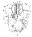
本発明の実施の形態について図1〜図4を参照しながら説明すると、先ず図1において、小型車両である揺動式自動三輪車が備える車体Bの中央部には、前面にウインドスクリーン21を配置したルーフ付きのキャビン22が、底面を低床式のフロア23とするようにして形成されており、該キャビン22の前壁に操向ハンドル24が支持され、車両運転者を座らせるための乗車用シート25が前記キャビン22内で操向ハンドル24の後方に配置される。また車体Bの前部には、前記操向ハンドル24で操向される単一の前輪WFが操向可能に懸架され、前記乗車用シート25の下方で車体BにはユニットスイングエンジンUEの前部が揺動連結機構26を介して連結され、左右一対の後輪WR…がユニットスイングエンジンUEの後部に軸支されている。When described with reference to FIGS. 1 to 4 in form ofimplementation of the present invention, first, in FIG. 1, the central portion of the vehicle body B provided in the swing-type automatic tricycle is a small vehicle, the
前記揺動連結機構26は、車体Bの後方側下部に前後揺動を可能として一端が連結されるリンク27と、ユニットスイングエンジンUEに設けられたブラケット29および前記リンク27の他端間を結ぶジョイント28とから成り、ジョイント28は、前記リンク27の他端に前端が揺動可能に連結されるジョイントケース30と、該ジョイントケース30に前部が回転自在に挿入されるとともに後部が前記ブラケット29に取付けられるジョイント軸31と、ジョイントケース30およびジョイント軸31間に介設されるダンパ部32とを有するものである。 The
このような揺動連結機構26によって、ユニットスイングエンジンUEは、車体Bに対して上下に揺動自在かつ左右にローリング自在に支承されることになり、前記ジョイントケース30および車体B間にはクッションユニット33が設けられる。 By such a
図2において、前記ユニットスイングエンジンUEは、4サイクルであるエンジンEと、該エンジンEの出力を無段階に変速して伝動軸36に伝達するベルト式の無段変速機37と、無段変速機37および伝動軸36間に介設される遠心クラッチ38と、伝動軸36の回転動力を減速する減速歯車機構39と、駆動輪である左右一対の後輪WR,WRに個別に対応した左および右車軸41L,41Rおよび前記減速歯車機構39間に介設される差動歯車機構40とを備える。 In FIG. 2, the unit swing engine UE includes a four-cycle engine E, a belt-type continuously
前記エンジンEは、たとえば水冷式単気筒に構成されるものであり、そのエンジン本体42は、クランクケース43と、シリンダ軸線を車体Bの前後方向に沿わせた略水平としてクランクケース43から前方に延びるシリンダブロック44と、シリンダブロック44の前部に結合されるシリンダヘッド45と、シリンダヘッド45の前部に結合されるヘッドカバー46とを備える。 The engine E is configured, for example, as a water-cooled single cylinder, and the engine
クランクケース43に回転自在に支承されるクランクシャフト47の一端部は、揺動式自動三輪車の進行方向に沿う右側でクランクケース43から突出されており、このクランクシャフト47の一端部にはAC発電機48が連結される。しかもAC発電機48の外方で前記クランクシャフト47にはクーリングファン49が固定される。 One end portion of the crankshaft 47 rotatably supported by the
一方、水冷式であるエンジンEからの冷却水を冷却するためのラジエータ50が、揺動式自動三輪車の進行方向前方に向かってエンジン本体42におけるシリンダブロック44およびシリンダヘッド45の右側方に配置される。しかも前記AC発電機48およびクーリングファン49を覆うラジエータシュラウド51が前記クランクケース43に結合されており、このラジエータシュラウド51には、前記ラジエータ50に後方から接続されるようにして前方に延びる導風部51aが一体に連設され、ラジエータ50は導風部51aの前部に結合、支持される。 On the other hand, a
而してクランクシャフト47とともにクーリングファン49が回転するのに応じて、前方からラジエータ50を通過するように外部からの冷却風がラジエータシュラウド51内に吸引され、エンジン本体42のシリンダヘッド45からラジエータ50に導かれた冷却水が前記ラジエータ50で冷却風により冷却される。 Thus, as the
揺動式自動三輪車の進行方向に沿う左側で前記クランクケース43には、該クランクケース43から後方に延びる中間ケース53が連結されており、この中間ケース53の右側に締結される右ケース54と、前記中間ケース53の左側に締結される左ケース55と、前記中間ケース53とで、エンジン本体42のクランクケース43に連設される伝動ケース56が構成される。 An
この伝動ケース56に、前記無段変速機37、前記遠心クラッチ38、前記減速歯車機構39および前記差動歯車機構40が収容されるものであり、前記無段変速機37および前記遠心クラッチ38は、中間ケース53および左ケース55間に形成される変速機室57に収容され、前記減速歯車機構39および差動歯車機構40は、前記中間ケース53および右ケース54間に形成される歯車室58に収容される。而して右ケース54は、前記中間ケース53との間に前記減速歯車機構39を収容するようにして皿状に形成される減速歯車機構収容部54aと、該減速歯車機構収容部54aから側方に突出した筒状に形成されるとともに前記差動歯車機構40を収容する差動歯車機構収容部54bとを一体に有する。 The
ところで左右一対の後輪WR,WRは、前記伝動ケース56の両側に配置されており、左および右車軸41L,41Rは差動歯車機構40から左右に延出され、伝動ケース56からの前記左および右車軸41L,41Rの突出端部に後輪WR,WRがそれぞれ連結され、それらの後輪WR,WRにはドラムブレーキBR,BRがそれぞれ装着される。 Incidentally, the pair of left and right rear wheels WR and WR are disposed on both sides of the
無段変速機37は、変速機室57内でクランクシャフト47の一端部に装着される駆動プーリ60と、クランクシャフト47と平行な軸線を有して伝動ケース56に回転自在に支承される伝動軸36に遠心クラッチ38を介して装着される被動プーリ61と、駆動プーリ60および被動プーリ61に巻掛けられる無端状のVベルト62とを備える。 The continuously
駆動プーリ60は、クランクシャフト47の一端側に固定される固定プーリ半体63と、固定プーリ半体63よりも軸方向内方側でクランクシャフト47に軸方向摺動可能に装着される可動プーリ半体64とで構成され、両プーリ半体63,64間にVベルト62が巻き掛けられる。また可動プーリ半体64の背面側でクランクシャフト47にはランププレート65が固着され、可動プーリ半体64およびランププレート65間には複数のウエイトローラ66…が浮動状態で収容される。而してクランクシャフト47の回転数が増大すると、遠心力を受けるウエイトローラ66…がクランクシャフト47の半径方向外方に移動して可動プーリ半体64を固定プーリ半体63に近接させる。それにより両プーリ半体63,64へのVベルト62の接触半径が大きくなる。 The
伝動軸36は中間ケース53を回転自在に貫通するものであり、伝動軸36の一端部は右側ケース55に回転自在に支承され、伝動軸36の他端部は左側ケース54に回転自在に支承され、伝動軸36の中間部は中間ケース53に回転自在に支承される。 The
一方、被動プーリ61は、相対回転を可能として伝動軸36を同軸に囲繞する筒部材67と、筒部材67に固定される固定プーリ半体68と、該固定プーリ半体68に対向する可動プーリ半体69と、該可動プーリ半体69および固定プーリ半体68間の相対回転位相差に応じて両プーリ半体68,69間に軸方向の分力を作用せしめるトルクカム機構70と、可動プーリ半体69を固定プーリ半体68側に向けて弾発付勢するコイルスプリング71とを備え、固定プーリ半体68および可動プーリ半体69間にVベルト62が巻き掛けられる。また筒部材67および伝動軸36間には、エンジン回転数が設定回転数を超えるのに伴って動力伝達状態となる遠心クラッチ38が設けられる。 On the other hand, the driven
而して被動プーリ61における固定プーリ半体68および可動プーリ半体69間の間隔は、前記トルクカム機構70によって生じる軸方向の力と、コイルスプリング71によって生じる軸方向の弾性力と、固定プーリ半体68および可動プーリ半体69間の間隔をあける方向に作用するVベルト62からの力とのバランスにより決定され、駆動プーリ60において可動プーリ半体64を固定プーリ半体63に近接させることによりVベルト62の駆動プーリ60への巻き掛け半径が大きくなると、Vベルト62の被動プーリ61への巻き掛け半径が小さくなる。 Thus, the distance between the fixed
遠心クラッチ38は、前記被動プーリ61および左側の後輪WR間に配置されるものであり、椀状に形成されて前記伝動軸36の一端部に固定されるクラッチアウタ72と、前記筒部材67に固定されるドライブプレート73と、前記クラッチアウタ72の内周に摩擦、係合することを可能として前記ドライブプレート73の複数箇所に支持される遠心ウエイト74…と、各遠心ウエイト74…および前記ドライブプレート73間に設けられるクラッチばね75…とを備える。 The centrifugal clutch 38 is disposed between the driven
この遠心クラッチ38は、固定プーリ半体63が固定される前記筒部材67および前記ドライブプレート73の回転に応じて各遠心ウエイト74…に作用する遠心力が前記各クラッチばね75…のばね付勢力を上回ったときに遠心ウエイト74…がクラッチアウタ72の内周に摩擦係合することで、前記筒部材67および前記伝動軸36間を動力伝達状態とする。 In the centrifugal clutch 38, the centrifugal force acting on the
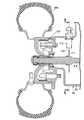
図3において、前記歯車室58に収納される減速歯車機構39は、伝動軸36に設けられる駆動歯車77と、伝動軸36および車軸41L,41Rと平行にして中間ケース53および右側ケース54に回転自在に支承されるアイドル軸81に固定されて駆動歯車77に噛合する第1アイドル歯車78と、アイドル軸81に一体に設けられる第2アイドル歯車79と、第2アイドル歯車79に噛合して前記車軸41L,41Rと同軸に配置される被動歯車80とから成る。 In FIG. 3, the
差動歯車機構40は、左右の車軸41L,41Rを同軸にそれぞれ囲繞する一対の円筒部82a,82bを有するキャリア部材82と、前記車軸41L,41Rの軸線と直交する軸線を有するとともに軸方向移動をピン83で阻止されるようにして前記キャリア部材82に両端部が支持される差動小歯車軸84と、前記キャリア部材82内で前記差動小歯車軸84に回転自在に支承される一対の差動小歯車85,86と、前記差動小歯車軸84の両側に配置されて前記車軸41L,41Rの内端部に固定されるとともに前記差動小歯車85,86に噛合する一対の差動大歯車87,88とを備える。 The
ところで伝動ケース56のうち前記中間ケース53は、変速機室57および歯車室58間を隔てる隔壁部53aを有しており、前記キャリア部材82の左側の円筒部82aはボールベアリング89を介して前記隔壁部53aで回転自在に支承され、この円筒部82aに被動歯車80が固定される。またキャリア部材82の右側の円筒部82bは右ケース54にボールベアリング90を介して回転自在に支承される。 By the way, the
また前記隔壁部53aとの間に環状のシール部材91を介在させて前記隔壁部53aを回転自在に貫通する左車軸41Lは左側の前記円筒部82a内に同軸に挿入され、前記右ケース54との間に環状のシール部材92を介在させて右ケース54を回転自在に貫通する右車軸41Rは右側の前記円筒部82b内に同軸に挿入される。 Further, a
ところで前記差動歯車機構40のキャリア部材82は、前記減速歯車機構39の出力端である被動歯車80よりも小径にして該被動歯車80の側方に配置されており、左および右車軸41L,41Rの少なくとも一方とともに回転するようにしてそれらの車軸41L,41Rと同軸に配置されるのであるが、後輪WRの車輪速を検出する車速センサ95が回転部材としての前記キャリア部材82の外周に検出部95aを対向させて前記伝動ケース56における右ケース54の差動歯車機構収容部54bに取付けられる。 By the way, the
前記車速センサ95は、前記キャリア部材82で支持されるとともに両端部を前記キャリア部材82の外面に臨ませた差動小歯車軸84の少なくとも一端、この実施の形態では差動小歯車軸84の一端の突出部84aを、前記キャリア部材82の外面に対向させた検出部95aで検出するように配置されるものである。 The
前記突出部84aの前記キャリア部材82の外面からの突出量は精密に設定されており、キャリア部材の82の回転中心すなわち前記両車軸41L,41Rの軸線からの距離が前記突出部84aを除く部分では一定となるように前記キャリア部材82の外面が研削加工される。なお差動小歯車軸84の両端をキャリア部材82の外面から一定量だけ突出させ、前記検出部95aで差動小歯車軸84の両端を検出するようにしてもよい。 The protruding amount of the protruding
しかも前記車速センサ95は、前記キャリア部材82の回転軸線に直交して前記差動小歯車軸84の中心軸線を通る平面PLよりも減速歯車機構39側に検出部95aの中心をオフセットさせて配置されるようにして差動歯車機構収容部54bに取付けられるものであり、図3で示すように、検出部95aの中心軸線CSは、前記平面PLからオフセット量δだけ減速歯車機構39側にオフセットした位置に配置される。 In addition, the
ところで前記差動歯車機構40の後方には、前記歯車室58に大部分が収容されるようにしてパーキングブレーキ機構96が配置される。このパーキングブレーキ機構96は、一端部を前記伝動ケース56における減速歯車機構収容部54aから一端部を突出させるようにして前記中間ケース53および前記右ケース54で回動自在に支承される回動軸97と、該回動軸97の前記減速歯車機構収容部54aからの突出端部に固定されるドラム98と、前記伝動軸36に固着される歯車99と、前記伝動軸36および前記回動軸97と平行な軸線を有して前記中間ケース53および前記右ケース54で回動自在に支承される軸100に固定されて前記歯車99に噛合し得るアーム101と、前記回動軸97および前記アーム101間を連結する連結機構102と、伝動ケース56および前記回動軸97間に向けられるねじりばね103とを備えるものであり、前記歯車99に前記アーム101を噛合させたパーキングブレーキ状態と、前記歯車99への前記アーム101の噛合を解除したパーキングブレーキ解除状態と、前記回動軸97の回動によって切換可能である。 By the way, a
図4を併せて参照して、前記ドラム98を覆うカバー104が、前記伝動ケース56減速歯車機構収容部54aの後部に締結されており、前記車速センサ95は、前記差動歯車機構40の後方に配置されるパーキングブレーキ機構96側すなわち前記カバー104側からボルト106によって前記差動歯車機構収容部54bに取付けられる。 Referring also to FIG. 4, a
しかも前記ドラム98に巻き掛け、連結されるブレーキケーブル105が前記カバー104内に挿入されるのであるが、このブレーキケーブル105の上方に前記車速センサ95が配置される。 Moreover, the
次に前記した実施の形態の作用について説明すると、減速歯車機構39の被動歯車80は、左右一対の車軸41L,41Rと同軸に配置されており、この被動歯車80よりも小径にして該被動歯車80の側方に配置される回転部材であるキャリア部材82が両車軸41L,41Rの少なくとも一方とともに回転するようにして両車軸41L,41Rと同軸に配置され、車速センサ95が前記キャリア部材82の外周に対向して伝動ケース56に取付けられるので、車軸41L,41Rの中心軸線から車速センサ95までの距離を小さくして、車速センサ95の取付けスペースを小さくし、車速センサ95の保護を容易とすることができる。Now be described the operation of theembodiment described above, the driven
しかも前記キャリア部材82は差動歯車機構40の一部を構成するものであり、該キャリア部材82で支持されるとともに両端部をキャリア部材82の外面に臨ませた差動小歯車軸84の少なくとも一端を検出するように車速センサ95が配置されるので、回転部材として専用の部材を設けることを不要として部品点数を低減するとともに組立性を高めることができ、また車軸41L,41Rと同軸でありながら左右の回転差の影響を受けずに正確な車速の検出が可能となる。 Moreover, the
また伝動ケース56は、減速歯車機構39を収容する減速歯車機構収容部54aと、該減速歯車機構収容部54aから側方に突出した筒状に形成されるとともに差動歯車機構40を収容する差動歯車機構収容部54bとを有しており、キャリア部材82の外面に対向する検出部95aを有する車速センサ95が、キャリア部材82の回転軸線に直交して前記差動小歯車軸84の中心軸線を通る平面PLよりも減速歯車機構39側に検出部95aの中心をオフセットさせて前記差動歯車機構収容部54bに取付けられるので、車速センサ95を減速歯車機構39に近接して配置して、減速歯車機構39を収容する減速歯車機構収容部54aの側壁で車速センサ95を保護することができる。 The
また車速センサ95が、差動歯車機構収容部54bの後方に配置されるパーキングブレーキ機構96側から差動歯車機構収容部54bに取付けられるので、パーキングブレーキ機構96で車速センサ95を後方から保護することができる。 Further, since the
さらにパーキングブレーキ機構96に連なるブレーキケーブル105の上方に車速センサ95が配置されるので、ブレーキケーブル105で車速センサ95を下方から保護することができる。 Further, since the
第1の参考実施形態について図5および図6を参照しながら説明するが、本発明の前記実施形態に対応する部分には同一の参照符号を付して図示するのみとし、詳細な説明は省略する。The first reference embodiment will be described with reference to FIG. 5 and FIG. 6, but the portions corresponding to the embodiment of thepresent invention are indicated by the same reference numerals, and the detailed description is omitted. To do.
無段変速機37を収容する変速機室57と、減速歯車機構39および差動歯車機構40を収容する歯車室58との間を隔てるようにして伝動ケース56の中間ケース53に設けられる隔壁部53aと、無段変速機37との間には、減速歯車機構39の被動歯車80よりも小径である回転部材108が、図2において鎖線で示すように、被動歯車80の側方に配置されており、この回転部材108は、図5および図6で示すように、左および右車軸41L,41Rのうち前記隔壁部53aを回転自在に貫通する左車軸41Lに固設され、回転部材108の外周には突部が突設される。而してこの参考実施形態では、回転部材108の外周の周方向に等間隔をあけた2箇所に突部108a,108aが突設され、それらの突部108a…を検出するようにして前記回転部材108の外周に対向して配置される車速センサ109が、前記隔壁部53aの前記変速機室57に臨む側面に取付けられる。A partition provided in the
しかも車速センサ109は、前記左車軸41Lの軸線と平行な方向でボルト110,110によって前記隔壁部53aに取付けられる。 Moreover, the
この参考実施形態によれば、無段変速機37のVベルト62との間の空きスペースを有効に利用して車速センサ109を配置することができ、伝動ケース56内に車速センサ109を配置することで車速センサ109を含むユニットスイングエンジンUEの小型化を図ることができる。According to thisreference embodiment, the
また車速センサ109が左車軸41Lの軸線と平行な方向で隔壁部53aに取付けられるので、車速センサ109の組み付け性を高めることができる。 Further, since the
次に第2の参考実施形態について図7および図8を参照しながら説明するが、本発明の実施形態及び参考実施形態に対応する部分には同一の参照符号を付して図示するのみとし、詳細な説明は省略する。Next, asecond reference embodiment will be described with reference to FIG. 7 and FIG. 8, but the portions corresponding to the embodiment of thepresent invention and the reference embodiment are only shown with the same reference numerals. Detailed description is omitted.
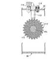
無段変速機37を収容する変速機室57内で、前記無段変速機37と、左右後輪WR…のうち無段変速機37を差動歯車機構40との間に挟む位置に配置される左後輪WRとの間には、減速歯車機構39の被動歯車80よりも小径である回転部材111が、図2において鎖線で示すように、被動歯車80の側方に配置されており、この回転部材111は、図7および図8で示すように、左車軸41Lに固設される。 Within the
前記回転部材111の外周には複数の歯112,112…が突設されており、それらの歯112,112…を検出するようにして前記回転部材111の外周に対向して配置される車速センサ113が、左車軸41Lよりも上方に配置されつつ前記伝動ケース56における左ケース55の上部に取付けられる。 A plurality of
この第2の参考実施形態によれば、車速センサ113を左後輪WRおよび伝動ケース56間に配置することで保護しつつ、車軸41Lよりも上方に在ることで下方からの車速センサ113の保護を図ることができる。According to thesecond reference embodiment , the
本発明の参考例について図9および図10を参照しながら説明するが、上記各実施形態に対応する部分には同一の参照符号を付して図示するのみとし、詳細な説明は省略する。Reference examples of the present invention will be described with reference to FIG. 9 and FIG. 10, but the portions corresponding to the above-describedembodiments are only given the same reference numerals and are not illustrated in detail.
前記無段変速機37における被動プーリ61の外方には遠心クラッチ38が配置されるが、この遠心クラッチ38のクラッチアウタ72には、回転部材116が同軸に固定され、この回転部材116の外周の周方向に等間隔をあけた2箇所に突設される突部117,117を検出するようにして前記回転部材116の外周に対向する車速センサ118が、左後輪WRのドラムブレーキBRよりも内方かつ遠心クラッチ38よりも上方に配置されつつ前記伝動ケース56における左ケース55の上部にボルト119,119で取付けられる。 A
この参考例によれば、車速センサ119をドラムブレーキBRおよび伝動ケース56間に配置することで車速センサ119の保護を図ることができるとともに、車軸41L,41Rとの間に差動歯車機構40および減速歯車機構39を介在させた伝動軸36の回転速度を検出するので、回転速度の速い部分で検出することによる検出精度の向上を図るとともに車速センサ119の小型化を図ることができる。 According to this reference example, it is possible to protect the
以上、本発明の実施の形態および参考実施形態について説明したが、本発明は上記実施の形態に限定されるものではなく、特許請求の範囲に記載された本発明を逸脱することなく種々の設計変更を行うことが可能である。Although the embodimentand the reference embodiment of the present invention have been described above, the present invention is not limited to the above-described embodiment, and various designs can be made without departing from the present invention described in the claims. It is possible to make changes.
36・・・伝動軸
37・・・無段変速機
39・・・減速歯車機構
40・・・差動歯車機構
41L,41R・・・車軸
42・・・エンジン本体
53a・・・隔壁部
54a・・・減速歯車機構収容部
54b・・・差動歯車機構収容部
56・・・伝動ケース
57・・・変速機室
58・・・歯車室
80・・・被動歯車
82・・・回転部材であるキャリア部材
84・・・差動小歯車軸
95・・・車速センサ
95a・・・検出部
96・・・パーキングブレーキ機構
105・・・ブレーキケーブル
B・・・車体
E・・・エンジン
PL・・・平面
UE・・・ユニットスイングエンジン
WR・・・駆動輪である後輪36 ...
Claims (3)
Translated fromJapanese前記差動歯車機構(40)が、前記被動歯車(80)よりも小径にして該被動歯車(80)の側方に配置されるキャリア部材(82)と、そのキャリア部材(82)で支持されるとともに両端部を該キャリア部材(82)の外面に臨ませた差動小歯車軸(84)とを備えると共に、そのキャリア部材(82)が、前記両車軸(41L,41R)の少なくとも一方とともに回転するようにして前記両車軸(41L,41R)と同軸に配置されるものにおいて、
前記キャリア部材(82)の外周に対向した検出部(95a)を有する車速センサ(95)が、前記差動小歯車軸(84)の、前記キャリア部材(82)外面に臨ませた少なくとも一端を前記検出部(95a)で検出するように配置され、
前記伝動ケース(56)が、前記減速歯車機構(39)を収容する減速歯車機構収容部(54a)と、該減速歯車機構収容部(54a)から側方に突出した筒状に形成されるとともに前記差動歯車機構(40)を収容する差動歯車機構収容部(54b)とを有しており、
前記車速センサ(95)は、前記キャリア部材(82)の回転軸線に直交して前記差動小歯車軸(84)の中心軸線を通る平面(PL)よりも前記減速歯車機構(39)側に前記検出部(95a)の中心をオフセットさせて、前記伝動ケース(56)の前記差動歯車機構収容部(54b)に取付けられることを特徴とする小型車両における車速検出構造。An engine (E), a continuously variable transmission (37) that continuously changes the output of the engine (E) and transmits the output to the transmission shaft (36), and the rotational power of the transmission shaft (36) is reduced. A reduction gear mechanism (39) that outputs from the driven gear (80), a pair of left and right axles (41L, 41R) arranged coaxially with the driven gear (80), and the reduction gear mechanism (39) are interposed. A transmission gear (56) connected to the engine body (42) of the engine (E), the continuously variable transmission (37), and the reduction gear mechanism (39). ) And a unit swing engine (UE) in which the differential gear mechanism (40) is housed are swingably supported on the vehicle body (B), and left and right drive wheels individually connected to the two axles (41L, 41R). (WR) is the transmission case (56)A small-sized vehicle which is arranged on right and leftsides,
The differential gear mechanism (40) issupported by acarrier member (82) having a smaller diameter than the driven gear (80) and disposed on the side of the driven gear (80), and the carrier member (82). And a differential small gear shaft (84) with both ends facing the outer surface of the carrier member (82), and the carrier member (82) is connected to at least one of the two axles (41L, 41R). the so as to rotate both axles (41L, 41R) andthe shall is disposedcoaxially,
A vehicle speed sensor (95) having a detection part (95a) facing the outer periphery of the carrier member (82) has at least one end of the differential small gear shaft (84) facing the outer surface of the carrier member (82). Arranged to be detected by the detector (95a),
The transmission case (56) is formed into a reduction gear mechanism housing portion (54a) for housing the reduction gear mechanism (39), and a cylindrical shape protruding sideways from the reduction gear mechanism housing portion (54a). A differential gear mechanism accommodating portion (54b) for accommodating the differential gear mechanism (40);
The vehicle speed sensor (95) is closer to the reduction gear mechanism (39) than a plane (PL) passing through the central axis of the differential small gear shaft (84) perpendicular to the rotational axis of the carrier member (82). the mainly by offsetting the detector (95a), said differential gear mechanism housing section speed detectionstructure in small vehicle, characterized in thatattached to (54b) of the transmission case(56).
Priority Applications (1)
| Application Number | Priority Date | Filing Date | Title |
|---|---|---|---|
| JP2010137921AJP5513274B2 (en) | 2010-06-17 | 2010-06-17 | Vehicle speed detection structure for small vehicles |
Applications Claiming Priority (1)
| Application Number | Priority Date | Filing Date | Title |
|---|---|---|---|
| JP2010137921AJP5513274B2 (en) | 2010-06-17 | 2010-06-17 | Vehicle speed detection structure for small vehicles |
Publications (2)
| Publication Number | Publication Date |
|---|---|
| JP2012001099A JP2012001099A (en) | 2012-01-05 |
| JP5513274B2true JP5513274B2 (en) | 2014-06-04 |
Family
ID=45533580
Family Applications (1)
| Application Number | Title | Priority Date | Filing Date |
|---|---|---|---|
| JP2010137921AActiveJP5513274B2 (en) | 2010-06-17 | 2010-06-17 | Vehicle speed detection structure for small vehicles |
Country Status (1)
| Country | Link |
|---|---|
| JP (1) | JP5513274B2 (en) |
Cited By (1)
| Publication number | Priority date | Publication date | Assignee | Title |
|---|---|---|---|---|
| WO2017114423A1 (en)* | 2015-12-31 | 2017-07-06 | Byd Company Limited | Electric drive axle assembly and vehicle having the electric drive axle assembly |
Families Citing this family (1)
| Publication number | Priority date | Publication date | Assignee | Title |
|---|---|---|---|---|
| CN110857024B (en)* | 2018-08-24 | 2021-02-26 | 重庆宗申无级变速传动有限公司 | Power assembly for electric automobile |
Family Cites Families (6)
| Publication number | Priority date | Publication date | Assignee | Title |
|---|---|---|---|---|
| JPS6148366U (en)* | 1984-08-31 | 1986-04-01 | ||
| JPH0545295U (en)* | 1991-11-15 | 1993-06-18 | 三菱自動車工業株式会社 | Ratio confirmation device |
| JPH07167255A (en)* | 1993-12-16 | 1995-07-04 | Kaaz Corp | Differential limiting device |
| JPH08133036A (en)* | 1994-11-14 | 1996-05-28 | Toyota Motor Corp | Wheel speed detector |
| JP4057259B2 (en)* | 2001-08-06 | 2008-03-05 | 本田技研工業株式会社 | Vehicle speed sensor mounting structure |
| JP4785726B2 (en)* | 2006-12-15 | 2011-10-05 | 本田技研工業株式会社 | Power unit for vehicle |
- 2010
- 2010-06-17JPJP2010137921Apatent/JP5513274B2/enactiveActive
Cited By (1)
| Publication number | Priority date | Publication date | Assignee | Title |
|---|---|---|---|---|
| WO2017114423A1 (en)* | 2015-12-31 | 2017-07-06 | Byd Company Limited | Electric drive axle assembly and vehicle having the electric drive axle assembly |
Also Published As
| Publication number | Publication date |
|---|---|
| JP2012001099A (en) | 2012-01-05 |
Similar Documents
| Publication | Publication Date | Title |
|---|---|---|
| US8002062B2 (en) | Drive unit for hybrid vehicle | |
| TWI360612B (en) | Straddle-type vehicle and power unit | |
| EP2233390B1 (en) | Motor-driven vehicle | |
| JP6372671B2 (en) | Electric assist bicycle | |
| JP6226120B2 (en) | Electric assist bicycle | |
| JP5513274B2 (en) | Vehicle speed detection structure for small vehicles | |
| JPWO2006003904A1 (en) | V-belt type continuously variable transmission for small vehicle and saddle riding type vehicle | |
| JPH08175477A (en) | Power switching device of engine and motor of motor cycle | |
| JP7210154B2 (en) | Manpowered vehicle rotation device | |
| JP6238357B2 (en) | Power transmission device for saddle-ride type vehicles | |
| JP5506223B2 (en) | Motor drive vehicle | |
| JP3793395B2 (en) | Wheel speed detection device for motorcycles | |
| CN103010367A (en) | Two-wheel motorcycle | |
| JP2014190364A (en) | Power transmission device of saddle ride type vehicle | |
| JPWO2014027386A1 (en) | Electric assist bicycle | |
| TW202402615A (en) | Hub assembly for human-powered vehicle | |
| CN111731429B (en) | Rear wheel brake device for motor bicycle | |
| JP5506222B2 (en) | Motor drive vehicle | |
| JP4664773B2 (en) | Arrangement structure of electric motor for shifting in motorcycle | |
| JP2017154676A (en) | Saddle-type hybrid vehicle | |
| JP6182202B2 (en) | Power transmission device for saddle-ride type vehicles | |
| JP5147444B2 (en) | Motorcycle | |
| JP6936281B2 (en) | Saddle-riding vehicle | |
| EP2065620B1 (en) | Motorcycle | |
| JP5568351B2 (en) | Power unit for small vehicles |
Legal Events
| Date | Code | Title | Description |
|---|---|---|---|
| A621 | Written request for application examination | Free format text:JAPANESE INTERMEDIATE CODE: A621 Effective date:20121127 | |
| A977 | Report on retrieval | Free format text:JAPANESE INTERMEDIATE CODE: A971007 Effective date:20130718 | |
| A131 | Notification of reasons for refusal | Free format text:JAPANESE INTERMEDIATE CODE: A131 Effective date:20130821 | |
| A521 | Written amendment | Free format text:JAPANESE INTERMEDIATE CODE: A523 Effective date:20131021 | |
| TRDD | Decision of grant or rejection written | ||
| A01 | Written decision to grant a patent or to grant a registration (utility model) | Free format text:JAPANESE INTERMEDIATE CODE: A01 Effective date:20140305 | |
| A61 | First payment of annual fees (during grant procedure) | Free format text:JAPANESE INTERMEDIATE CODE: A61 Effective date:20140327 | |
| R150 | Certificate of patent or registration of utility model | Ref document number:5513274 Country of ref document:JP Free format text:JAPANESE INTERMEDIATE CODE: R150 |