JP5511984B2 - Vehicle travel support device - Google Patents
Vehicle travel support deviceDownload PDFInfo
- Publication number
- JP5511984B2 JP5511984B2JP2012548636AJP2012548636AJP5511984B2JP 5511984 B2JP5511984 B2JP 5511984B2JP 2012548636 AJP2012548636 AJP 2012548636AJP 2012548636 AJP2012548636 AJP 2012548636AJP 5511984 B2JP5511984 B2JP 5511984B2
- Authority
- JP
- Japan
- Prior art keywords
- vehicle
- state
- control
- inter
- traffic
- Prior art date
- Legal status (The legal status is an assumption and is not a legal conclusion. Google has not performed a legal analysis and makes no representation as to the accuracy of the status listed.)
- Expired - Fee Related
Links
Images


Classifications
- B—PERFORMING OPERATIONS; TRANSPORTING
- B60—VEHICLES IN GENERAL
- B60W—CONJOINT CONTROL OF VEHICLE SUB-UNITS OF DIFFERENT TYPE OR DIFFERENT FUNCTION; CONTROL SYSTEMS SPECIALLY ADAPTED FOR HYBRID VEHICLES; ROAD VEHICLE DRIVE CONTROL SYSTEMS FOR PURPOSES NOT RELATED TO THE CONTROL OF A PARTICULAR SUB-UNIT
- B60W30/00—Purposes of road vehicle drive control systems not related to the control of a particular sub-unit, e.g. of systems using conjoint control of vehicle sub-units
- B60W30/14—Adaptive cruise control
- B60W30/16—Control of distance between vehicles, e.g. keeping a distance to preceding vehicle
- G—PHYSICS
- G08—SIGNALLING
- G08G—TRAFFIC CONTROL SYSTEMS
- G08G1/00—Traffic control systems for road vehicles
- G—PHYSICS
- G08—SIGNALLING
- G08G—TRAFFIC CONTROL SYSTEMS
- G08G1/00—Traffic control systems for road vehicles
- G08G1/16—Anti-collision systems
- G08G1/166—Anti-collision systems for active traffic, e.g. moving vehicles, pedestrians, bikes
- G—PHYSICS
- G08—SIGNALLING
- G08G—TRAFFIC CONTROL SYSTEMS
- G08G1/00—Traffic control systems for road vehicles
- G08G1/16—Anti-collision systems
- G08G1/167—Driving aids for lane monitoring, lane changing, e.g. blind spot detection
- B—PERFORMING OPERATIONS; TRANSPORTING
- B60—VEHICLES IN GENERAL
- B60W—CONJOINT CONTROL OF VEHICLE SUB-UNITS OF DIFFERENT TYPE OR DIFFERENT FUNCTION; CONTROL SYSTEMS SPECIALLY ADAPTED FOR HYBRID VEHICLES; ROAD VEHICLE DRIVE CONTROL SYSTEMS FOR PURPOSES NOT RELATED TO THE CONTROL OF A PARTICULAR SUB-UNIT
- B60W50/00—Details of control systems for road vehicle drive control not related to the control of a particular sub-unit, e.g. process diagnostic or vehicle driver interfaces
- B60W2050/0062—Adapting control system settings
- B60W2050/0075—Automatic parameter input, automatic initialising or calibrating means
- B—PERFORMING OPERATIONS; TRANSPORTING
- B60—VEHICLES IN GENERAL
- B60W—CONJOINT CONTROL OF VEHICLE SUB-UNITS OF DIFFERENT TYPE OR DIFFERENT FUNCTION; CONTROL SYSTEMS SPECIALLY ADAPTED FOR HYBRID VEHICLES; ROAD VEHICLE DRIVE CONTROL SYSTEMS FOR PURPOSES NOT RELATED TO THE CONTROL OF A PARTICULAR SUB-UNIT
- B60W2554/00—Input parameters relating to objects
- B60W2554/80—Spatial relation or speed relative to objects
- B60W2554/801—Lateral distance
- B—PERFORMING OPERATIONS; TRANSPORTING
- B60—VEHICLES IN GENERAL
- B60W—CONJOINT CONTROL OF VEHICLE SUB-UNITS OF DIFFERENT TYPE OR DIFFERENT FUNCTION; CONTROL SYSTEMS SPECIALLY ADAPTED FOR HYBRID VEHICLES; ROAD VEHICLE DRIVE CONTROL SYSTEMS FOR PURPOSES NOT RELATED TO THE CONTROL OF A PARTICULAR SUB-UNIT
- B60W40/00—Estimation or calculation of non-directly measurable driving parameters for road vehicle drive control systems not related to the control of a particular sub unit, e.g. by using mathematical models
- B60W40/10—Estimation or calculation of non-directly measurable driving parameters for road vehicle drive control systems not related to the control of a particular sub unit, e.g. by using mathematical models related to vehicle motion
- B—PERFORMING OPERATIONS; TRANSPORTING
- B60—VEHICLES IN GENERAL
- B60W—CONJOINT CONTROL OF VEHICLE SUB-UNITS OF DIFFERENT TYPE OR DIFFERENT FUNCTION; CONTROL SYSTEMS SPECIALLY ADAPTED FOR HYBRID VEHICLES; ROAD VEHICLE DRIVE CONTROL SYSTEMS FOR PURPOSES NOT RELATED TO THE CONTROL OF A PARTICULAR SUB-UNIT
- B60W50/00—Details of control systems for road vehicle drive control not related to the control of a particular sub-unit, e.g. process diagnostic or vehicle driver interfaces
- B60W50/08—Interaction between the driver and the control system
- B60W50/082—Selecting or switching between different modes of propelling
- G—PHYSICS
- G08—SIGNALLING
- G08G—TRAFFIC CONTROL SYSTEMS
- G08G1/00—Traffic control systems for road vehicles
- G08G1/16—Anti-collision systems
Landscapes
- Engineering & Computer Science (AREA)
- Physics & Mathematics (AREA)
- General Physics & Mathematics (AREA)
- Automation & Control Theory (AREA)
- Transportation (AREA)
- Mechanical Engineering (AREA)
- Human Computer Interaction (AREA)
- Traffic Control Systems (AREA)
- Control Of Driving Devices And Active Controlling Of Vehicle (AREA)
Description
Translated fromJapanese本発明は、車両の走行支援装置に関し、より具体的には、自車両の加速度と他の車両との車間距離とから交通流の状態を判定し、その判定結果に応じて車両の走行制御を切り替える機能を備える車両の走行支援装置に関する。 The present invention relates to a vehicle travel support device, and more specifically, determines the state of traffic flow from the acceleration of the host vehicle and the inter-vehicle distance from another vehicle, and performs vehicle travel control according to the determination result. The present invention relates to a vehicle travel support device having a switching function.
従来から、渋滞抑制または回避のための走行制御装置が提案されている。例えば、特許文献1には、車両が走行する道路の車両密度を含む交通状態を取得し、道路の車両密度が臨界密度に近づくほど車間距離が短くなりにくくなるように車両の走行制御を行うことにより、交通流が渋滞流となることを抑制又は回避することが記載されている。 Conventionally, a travel control device for suppressing or avoiding traffic congestion has been proposed. For example,
しかし、特許文献1を含む従来の方法では、車両密度を用いた渋滞予測の判定精度が必ずしも高いとは言えず、渋滞の回避あるいは解消のためにはさらなる改善の余地がある。 However, in the conventional method including
したがって、本発明の目的は、交通流の判定(推定)精度を適切に向上させて、渋滞の回避あるいは解消のために有効となる走行制御が可能な車両の走行支援装置を提供することである。 Accordingly, an object of the present invention is to provide a vehicle travel support device capable of appropriately improving the traffic flow determination (estimation) accuracy and capable of travel control effective for avoiding or eliminating traffic congestion. .
本発明は、自車両の加速度と、周辺の他車両との車間距離とに基づいて、自車両が走行する車線での交通流の状態を判定する判定手段と、自車両の走行を制御する走行制御手段であって、判定手段による判定結果に応じて、走行制御を切り替えることができる、走行制御手段とを備え、走行制御手段は、判定結果において、交通流の状態が、渋滞が発生する可能性が低い自由流の状態から車両の制動状態と加速状態が混合する混合流の状態へ移行する間に存在する臨界領域の状態であることを示す場合に、走行制御を切り替える、車両の走行支援装置である。 The present invention relates to determination means for determining a traffic flow state in a lane on which the host vehicle travels based on the acceleration of the host vehicle and an inter-vehicle distance from other vehicles in the vicinity, and travel for controlling the travel of the host vehicle. A travel control means that can switch the travel control according to a determination result by the determination means, and the travel control means is capable of causing a traffic jam in the determination result and a traffic flow state. Vehicle driving support that switches driving control when it indicates that the vehicle is in a critical region that exists during the transition from a free flow state to a mixed flow state where the braking state and acceleration state of the vehicle are mixed Device.
本発明によれば、自車両の加速度と、周辺の他車両との車間距離とに基づいて、交通流の状態が、自由流から混合流への移行する間に存在する臨界領域の状態にあると判定できる場合に、走行制御を切り替えるので、混合流への進行しいては渋滞への進行を未然に防ぐことが可能になる。 According to the present invention, based on the acceleration of the host vehicle and the inter-vehicle distance with other vehicles in the vicinity, the traffic flow is in a critical region that exists during the transition from the free flow to the mixed flow. When it can be determined that the travel control is switched, it is possible to prevent the traffic from progressing to the mixed flow if it proceeds to the mixed flow.
本発明の一形態によると、さらに、自車両に搭載された報知手段を制御する報知制御手段を備え、報知制御手段は、走行制御手段による走行制御の切り替えに応じて報知手段による報知内容を切り替える。 According to an aspect of the present invention, the information processing device further includes notification control means for controlling the notification means mounted on the host vehicle, and the notification control means switches notification contents by the notification means in accordance with switching of travel control by the travel control means. .
本発明の一形態によれば、交通流の状態が臨界領域の状態である場合に、運転者に走行制御の切り替えの報知をおこなうことにより、運転者に混合流への進行しいては渋滞への進行を防ぐための走行制御が必要であることを知らしめることができる。 According to one aspect of the present invention, when the traffic flow is in the critical region, the driver is notified of the switching of the traveling control, so that if the driver progresses to the mixed flow, the traffic flow becomes congested. It is possible to make it known that traveling control is necessary to prevent the progress of the vehicle.
本発明の一形態によると、走行制御手段は、自動定速走行機能を備え、走行制御の切り替えは自動定速走行機能をオンまたはオフすることを含む。 According to one aspect of the present invention, the traveling control means includes an automatic constant speed traveling function, and switching of the traveling control includes turning on or off the automatic constant speed traveling function.
本発明の一形態によれば、交通流の状態が臨界領域の状態である場合に、自動定速走行機能のオンまたはオフすることにより、渋滞への進行を未然に防ぐためにより適した走行制御をおこなうことが可能となる。 According to one aspect of the present invention, when the traffic flow is in a critical region, the travel control is more suitable for preventing the advance to a traffic jam by turning on or off the automatic constant speed travel function. Can be performed.
本発明の一形態によると、判定手段は、自車両の加速度から得られるパワースペクトルの単回帰直線から算出した傾き極大値の対数と、車間距離の分布から算出した共分散の最小値の対数との相関マップから交通流の状態を判定する。 According to one aspect of the present invention, the determination means includes a logarithm of a maximum slope value calculated from a single regression line of a power spectrum obtained from the acceleration of the host vehicle, and a logarithm of a minimum covariance value calculated from a distribution of inter-vehicle distances. The traffic flow state is determined from the correlation map.
本発明の一形態によれば、共分散値の最小値の対数と傾き極大値の対数との相関マップを得ることにより、車群分布における臨界領域の有無の判定をより精度良くおこなうことが可能になる。 According to one aspect of the present invention, by obtaining a correlation map between the logarithm of the minimum covariance value and the logarithm of the slope maximum value, it is possible to more accurately determine the presence or absence of a critical region in the vehicle group distribution. become.
図面を参照しながら本発明の実施の形態を説明する。図1は、本発明の一実施形態に従う、車両の走行支援装置100の構成を示すブロック図である。走行支援装置100は車両に搭載される。走行支援装置100は、1つの装置としてあるいは他の装置の一部として車両に搭載することができる。 Embodiments of the present invention will be described with reference to the drawings. FIG. 1 is a block diagram showing a configuration of a vehicle
走行支援装置100は、ヨーレートセンサ10、車速センサ11、レーダ装置12、ナビゲーション装置13、処理装置14、スイッチ15、各種アクチュエータ16、スピーカー17、表示器18、および通信装置19を備える形で構成される。なお、処理装置14は、ナビゲーション装置13の中に組み込んでもよい。また、スピーカー17および表示器18は、ナビゲーション装置13が備える該当機能を利用してもよい。 The
ヨーレートセンサ10は、自車両のヨーレートを検出し、その検出信号を処理装置14へ送る。車速センサ11は、自車両の加速度を検出し、その検出信号を処理装置14へ送る。レーダ装置12は、自車両の周辺に設定される所定の検出対象領域を複数の角度領域に分割し、各角度領域を走査(スキャン)しながら赤外光レーザやミリ波等の電磁波を発信する。レーダ装置12は、検出対象領域における物体からの反射信号(電磁波)を受信し、その反射信号を処理装置14へ送る。 The
ナビゲーション装置13は、GPS信号等の測位信号を受信して、その測位信号から自車両の現在位置を算出する。また、ナビゲーション装置13は、車速センサ11およびヨーレートセンサ(図示なし)等が検出した加速度およびヨーレートから自律航法を用いて自車両の現在位置を算出することもできる。ナビゲーション装置13は、地図データを備え、表示する地図上に自車両の現在位置、目的地までの経路情報や渋滞情報等を出力する機能を有する。 The
処理装置14は、周波数分析部31、単回帰直線算出部32、傾き極大値算出部33、反射点検出部34、他車両検出部35、車間距離検出部36、車間距離分布推定部37、共分散最小値算出部38、相関マップ作成部40、交通流判定部41、走行制御部42、報知制御部43、および通信制御部44を備える。各ブロックの機能は、処理装置14が有するコンピュータ(CPU)によって実現される。各ブロックの機能の詳細は後述する。 The
処理装置14は、ハードウエア構成として、例えば、入力アナログ信号をデジタル信号に変換するA/D変換回路、各種演算処理を行う中央演算処理装置(CPU)、CPUが演算に際してデータを記憶するのに使用するRAM、CPUが実行するプログラムおよび用いるデータ(テーブル、マップを含む)を記憶するROM、スピーカー17に対する駆動信号および表示器18に対する表示信号などを出力する出力回路を備えている。 The
スイッチ15は、自車両の走行制御に係る各種信号を処理装置14へ出力する。各種信号には、例えばアクセルペダルやブレーキペダルの操作(位置)信号、自動定速走行制御(ACC)に係る各種信号(制御開始、制御停止、目標車速、車間距離等)などを含むことができる。 The
各種アクチュエータ16は、複数のアクチュエータの総称として用いており、例えば、加速アクチュエータ(スロットルアクチュエータ等)、減速アクチュエータ(ブレーキアクチュエータ等)、ステアリングアクチュエータ等が含まれる。 The
表示器18は、LCD等のディスプレイを含み、タッチパネル機能を有するディスプレイとすることができる。表示装置16は、音声出力部および音声入力部を備える構成でもよい。表示器18は、報知制御部43からの制御信号に応じて、所定の警報情報を表示したり、所定の警告灯を点滅ないし点灯させることによって、運転者に報知する。スピーカー17は、報知制御部43からの制御信号に応じて所定の警報音や音声を出力することによって、運転者に報知する。 The
通信装置19は、通信制御部44による制御下で、無線通信によって他車両あるいはサーバ装置(図示なし)や中継局(図示なし)と通信を行い、渋滞予測部41から出力される渋滞予測結果と位置情報を対応付けて送信したり、他車両等から渋滞予測結果と位置情報との対応情報を受信する。取得された情報は、通信制御部44を介して報知制御部43あるいは走行制御部42に送られる。 The
次に処理装置14の各ブロックの機能について説明する。周波数分析部31は、車速センサ11が検出した自車両の加速度について周波数分析を行い、パワースペクトルを算出する。図2に2つの異なる走行状態(a)、(b)におけるパワースペクトルの例を示す。図2では、パワースペクトルとして周波数に対応した加速度スペクトル51、53が例示されている。 Next, the function of each block of the
単回帰直線算出部32は、得られたパワースペクトルに対して単回帰分析をおこない単回帰直線を算出する。図2の例では、符号52、54で指示される直線がそれぞれ加速度スペクトル51、53に対して得られる単回帰直線である。 The single regression
傾き極大値算出部33は、得られた単回帰直線から傾き極大値を算出する。図2の例では、最初に単回帰直線52、54の傾きを算出する。すなわち、図2において、所定の周波数範囲Y(例えば、数秒から数分の時間範囲に対応する周波数範囲、0〜0.5Hz等)でのスペクトル値の変化Xに基づき傾きα(=Y/X)を算出する。図2では(a)と(b)での傾きα1、α2が得られる。 The slope maximum
次に、得られた傾きαの差分、すなわち所定の時間間隔での傾きαkとαk−1との差分Δα(=αk―αk−1)を算出する。得られた差分Δαの時間変化、あるいは差分Δαから得られるパラメータ(例えば、2乗値(Δα)2、絶対値|Δα|等)の時間変化の極大値を求める。得られた極大値を傾き極大値として処理装置14内のメモリ(RAM等)に格納する。Next, a difference between the obtained inclinations α, that is, a difference Δα (= αk −αk−1 ) between the inclinations αk and αk−1 at a predetermined time interval is calculated. A time change of the obtained difference Δα or a maximum value of the time change of a parameter (for example, a square value (Δα)2 , an absolute value | Δα |, etc.) obtained from the difference Δα is obtained. The obtained maximum value is stored in a memory (RAM or the like) in the
反射点検出部34は、レーダ装置12が検出した反射信号から反射点(物体)の位置を検出する。他車両検出部35は、反射点検出部34から出力される反射点の位置情報に基づき、隣り合う反射点間の距離、反射点の分布状態等から自車両の周辺に存在する少なくとも1台以上の他車両を検出する。車間距離検出部36は、反射点検出部34が検出した他車両情報から自車両と他車両との間の車間距離を検出し、その結果を他車両の検出台数と共に出力する。 The
車間距離分布推定部37は、車間距離検出部36から出力される車間距離と車両台数の情報から車間距離分布を推定する。図3と図4を参照しながら車間距離分布推定について説明する。図3は確率密度分布を示す図である。 The inter-vehicle distance
車間距離と車両台数の情報から前方での車群、すなわち車間距離が比較的緻密な車の集合が観測できる場合、変分ベイズなどの分布推定法を用いて各車群に対してガウス分布(確率密度分布)を適用する。例えば2つの車群があるとした場合は、車群を2つのガウス分布を線形結合した分布として捉えることができる。 If a vehicle group ahead, that is, a set of cars with relatively small distance between vehicles, can be observed from the information on the distance between vehicles and the number of vehicles, a Gaussian distribution ( Apply probability density distribution. For example, when there are two vehicle groups, the vehicle group can be regarded as a distribution obtained by linearly combining two Gaussian distributions.
すなわち、図3に示すように、この2つのガウス分布を表わす確率関数P1(X)、P2(X)の和(重ね合わせ)として全体の分布を表す確率関数P(X)を得ることができる。That is, as shown in FIG. 3, a probability function P (X) representing the entire distribution can be obtained as the sum (superposition) of the probability functions P1 (X) and P2 (X) representing the two Gaussian distributions. .
ガウス分布(確率関数)をN(X|μ、Σ)で表すと、図3に例示されるような複数のガウス分布の重ね合わせは、次式で得ることができる。
共分散最小値算出部38は、得られたガウス分布P(X)について、例えば最尤法を用いて、対応する共分散値Σkを算出する。その際、例えば上記したP(X)から得られる尤度関数が最大となるパラメータ(共分散)を求めるためにEMアルゴリズム等を用いて計算をおこなう。ガウス分布P(X)が図4で例示されるような複数のガウス分布の重ね合わせとして得られる場合は、個々のガウス分布に対して共分散値Σkを算出する。The covariance minimum
共分散最小値算出部38は、各ガウス分布P(X)に対して得られた共分散値Σkの最小値を算出する。図4は共分散値Σkを模式的に表わした図である。図4(a)では、共分散値Σkを表わすグラフ56がデルタ(δ)0においてシャープなグラフとなっており、車群の変動が無い、すなわち車間距離がほぼ一定の走行状態にあることを示唆している。一方、図4(b)では、デルタ(δ)が負の領域のδ1でピークを持つグラフ57と正の領域のδ2でピークを持つグラフ58の2つのグラフが得られている。グラフ57、58ともに所定の変動幅(δ)を有しており、車群の変動が有る、言い換えれば車間距離が異なる車の集合が複数存在することを示唆している。図4において、共分散値Σkの最小値は(a)ではほぼゼロ(0)、(b)では小さいほうのδ1となる。The covariance minimum
図1の相関マップ作成部40は、傾き極大値算出部33により算出された傾き極大値と、共分散最小値算出部38によって算出された共分散最小値との相関マップを作成する。図6は、傾き極大値と共分散最小値との相関マップのイメージ(概念)図である。図6では、横(X)軸を共分散最小値Xとし、縦(Y)軸を傾き極大値Yとして、変数(X、Y)の相関をマッピングしている。符号59と60で指示される2つの領域が示されており、この2つの領域が重なっている境界領域61が存在している。領域59は比較的共分散最小値が小さく、車群の変動が小さい状態、言い換えれば車間距離が比較的一定しているような状態に相当する。逆に領域60は比較的共分散最小値が大きく、車群の変動が大きい状態、言い換えれば車間距離が異なる車の集合が複数存在する状態に相当する。境界領域61は、車群の変動が小さい状態から大きい状態へ遷移する領域であり、本発明はこの境界領域61に相当する車群の状態を定量的に見出して、渋滞予測をおこなうところに特徴がある。 The correlation
ここで図6を参照しながら、図5に例示した各領域についてさらに説明する。図6は、交通密度と交通量の関係を示す図である。グラフの横(X)軸は、自車両から所定距離内に存在する車両の台数を意味する交通密度である。この交通密度の逆数が車間距離に相当する。縦(Y)軸は、所定位置を通過する車両数を意味する交通量である。図6は、いわば車両の流れを意味する交通流を表わしていると捉える事ができる。 Here, the respective regions illustrated in FIG. 5 will be further described with reference to FIG. FIG. 6 is a diagram showing the relationship between traffic density and traffic volume. The horizontal (X) axis of the graph is a traffic density that means the number of vehicles existing within a predetermined distance from the host vehicle. The reciprocal of this traffic density corresponds to the inter-vehicle distance. The vertical (Y) axis is a traffic volume that means the number of vehicles passing through a predetermined position. It can be understood that FIG. 6 represents a traffic flow that means the flow of a vehicle.
図6で例示される交通流は、大きく4つの状態(領域)に区分けできる。1つめは、渋滞が発生する可能性が低い自由流の状態であって、ここでは一定以上の車速度および車間距離が確保可能である。2つめは車両の制動状態と加速状態が混合する混合流の状態である。この混合流の状態は、渋滞流に移行する前の状態であって、運転者による運転の自由度が低下して、交通流の低下と交通密度の増大(車間距離の縮小)によって渋滞流へと移行する確率が高い状態である。3つめは渋滞を示す渋滞流の状態である。4つめは自由流の状態から混合流の状態へ移行する間に存在する遷移状態である臨界領域の状態である。この状態は、自由流に比べて交通量および交通密度が高い状態であって、交通量の低下と交通密度の増大(車間距離の縮小)によって混合流へと移行する状態である。なお、臨界領域は、準安定流、メタ安定流と呼ばれることもある。 The traffic flow illustrated in FIG. 6 can be roughly divided into four states (regions). The first is a free flow state in which the possibility of traffic congestion is low, and here, a vehicle speed and an inter-vehicle distance above a certain level can be secured. The second is a mixed flow state in which the braking state and the acceleration state of the vehicle are mixed. This mixed flow state is the state before the transition to the congestion flow, and the degree of freedom of driving by the driver is reduced, and the traffic flow is reduced and the traffic density is increased (reduction of the inter-vehicle distance). It is in a state where the probability of transition is high. The third is a traffic flow state indicating a traffic jam. The fourth is a critical region state which is a transition state existing during the transition from the free flow state to the mixed flow state. This state is a state in which the traffic volume and the traffic density are higher than those in the free stream, and the state is shifted to a mixed stream due to a decrease in the traffic volume and an increase in the traffic density (a reduction in the inter-vehicle distance). The critical region is sometimes called metastable flow or metastable flow.
図5と図6との関係から、図5の領域59は図6の自由流および臨界領域の状態を含むことになり、図5の領域60は図6の混合流および渋滞流の状態を含むことになる。したがって、図5の境界領域は図6の臨界領域の状態と混合流の状態との双方を含む境界状態であり、ここでは図6に示すように臨界領域の境界と呼ぶ。本発明ではこの臨界領域の境界を含む臨界領域の状態を定量的に把握して、車線変更等の走行制御をおこなって渋滞の発生を防ぐあるいは渋滞を回避することが狙いである。 From the relationship between FIG. 5 and FIG. 6, the
図7を参照しながら臨界領域の状態の定量化について説明する。図7は、車間距離分布についての共分散最小値の対数と加速度スペクトルについての傾き極大値の対数との相関マップを示す図である。図7(a)は図6の交通流マップを簡略化して描いた図であり、(b)は共分散最小値の対数と傾き極大値の対数との相関マップを示す。(b)の共分散最小値の対数と傾き極大値の対数は、傾き極大値算出部33により算出された傾き極大値と、共分散最小値算出部38によって算出された共分散最小値との対数値として算出される。 The quantification of the critical region state will be described with reference to FIG. FIG. 7 is a diagram showing a correlation map between the logarithm of the minimum covariance value for the inter-vehicle distance distribution and the logarithm of the maximum slope value for the acceleration spectrum. FIG. 7A is a simplified drawing of the traffic flow map of FIG. 6, and FIG. 7B shows a correlation map between the logarithm of the minimum covariance value and the logarithm of the slope maximum value. The logarithm of the covariance minimum value and the logarithm of the slope maximum value in (b) is the difference between the slope maximum value calculated by the slope maximum
図7(b)において、符号62で指示される領域は(a)の臨界領域を含み、符号63で指示される領域は(a)の混合流の状態を含む。符号64で指示される線は臨界線であり、これを越えて混合流の状態へ移行すると渋滞に至ってしまう臨界点を意味する。領域62、63の境界領域65は臨界64直前の臨界領域の境界に相当する。図7(b)に例示される相関マップは処理装置14内のメモリ(RAM等)に格納される。 In FIG. 7B, the region indicated by
図1の交通流判定部41は、相関マップ作成部40によって作成された相関マップにおいて、交通流の種類を判定し、より具体的には交通流として臨界領域の状態が存在するか否かを判定する。そして、渋滞への移行を阻止すべく、走行制御部42、報知制御部43、および通信制御部44にその判定結果を含む制御信号を送る。これにより、後述する各種制御を実行して、図7に例示される混合流への移行を未然に阻止することが可能となり、その結果渋滞回避のみならず渋滞解消に役立つ渋滞予測が可能となる。 The traffic
また、交通流判定部41は、渋滞予測結果をナビゲーション装置13に出力する。ナビゲーション装置13は、交通流判定部41から受信した交通流の判定結果と、通信制御部41から出力される他車両において予測された交通流の判定結果あるいは渋滞予測結果とに基づき、渋滞を回避するように自車両の経路探索や経路誘導を行うことができる。 In addition, the traffic
走行制御部42は、交通流判定部41から出力される交通流判定結果と通信制御部44から出力される他車両等からの渋滞関連情報と、スイッチ15から出力される各種信号と、車速センサ11から出力される自車両の加速度の検出結果と、車間距離検出部36から出力される車間距離の検出結果とに基づき、各種アクチュエータを制御することにより、自車両の走行を制御する。 The
図8は、本発明の一実施形態に従う、走行制御部42の構成を示すブロック図である。走行制御部42は、基本構成として、車両の前方に先行車が検知されたときには、予め設定した目標車間距離を維持して該先行車に追従走行し、先行車が検知されないときには、予め設定された目標車速で定速走行する自動定速走行(ACC:アダプティブ・クルーズ・コントロール)システムを実現するよう構成されている。 FIG. 8 is a block diagram showing a configuration of
また、走行制御部42は、交通流判定部41から出力される交通流判定結果に応じて、ACC制御をオンまたはオフするように構成される。例えば、交通流判定結果が「臨界領域あり」の場合はACC制御をオフして、運転者の手動操作により車間距離が長くかつ制動回数が少なくなるような運転が行われるようにする。交通流判定結果が「臨界領域なし」あるいは「混合流の状態あり」の場合はACC制御をオンして、自動定速走行により所定の車間距離が維持可能な走行あるいは定速走行が行われるようにする。 The traveling
走行軌跡推定部421は、ヨーレートセンサ10によって検出されたヨーレートと、車速センサ11によって検出された加速度とに基づいて、自車両の将来の走行軌跡を推定する。具体的には、走行軌跡推定部421は、検出されたヨーレートおよび加速度から、車両の旋回半径を算出し、自車両の現在の進行方向に、算出した旋回半径の円弧を連ねることにより、自車両の将来の走行軌跡を推定することができる。 The travel
走行軌跡の推定には任意の手法を用いることができ、付加的に、または代替的に、他のセンサ等からの情報を用いてもよい。例えば、舵角センサを用いて、センサから検出されたステアリングホイールの舵角を用いてもよい。 Arbitrary methods can be used for estimating the travel locus, and information from other sensors or the like may be used additionally or alternatively. For example, you may use the steering angle of the steering wheel detected from the sensor using the steering angle sensor.
検知エリア設定部422は、推定された走行軌跡を中心線として、中心線に沿う所定幅の検知エリアを設定する。 The detection
先行車抽出部423は、レーダ装置12によって検知された物体のうち、検知エリア内に存在する車両を、追従対象(ターゲット)となる先行車として抽出する。なお、以下の説明において、ターゲットの決定を「ロックオン」と呼び、決定されたターゲットの解除を「ロックオフ」と呼ぶことがある。 The preceding
制御目標値決定部424は、先行車抽出部423によってターゲットが抽出された場合には、抽出されたターゲットに自車両を追従走行させるための目標車速および目標車間距離を含む制御目標値を決定する。これらの目標値の決定手法には、任意の適切な手法を用いることができる。例えば、自車両の現在の車速と、先行車への目標到達時間(例えば、乗員により、車間距離の所望の大きさに応じて設けられたスイッチ等を介して選択されることができる)とを乗算することにより算出した目標車間距離に到達するように、各制御サイクルの目標車速を決定することができる。 When the target is extracted by the preceding
他方、制御目標値決定部424は、先行車抽出部423によってターゲットが抽出されない場合には、定速走行を実現するための目標車速を含む制御目標値を決定する。制御目標値についても、任意の適切な手法で決定されることができ、例えば、所定のスイッチ等を介して乗員により設定された車速を目標車速とすることができる。 On the other hand, if the target is not extracted by the preceding
車両制御部425は、決定された制御目標値に基づいて、車両の加速アクチュエータ161および減速アクチュエータ162を駆動する。加速アクチュエータ161として、例えば、スロットルバルブの開度を制御するアクチュエータや、吸気バルブのリフト量を制御するアクチュエータがある。また、減速アクチュエータ162として、ブレーキの作動を制御するブレーキ装置がある。車両制御部425は、これらのアクチュエータの駆動を介して、決定された目標車速および目標車間距離を実現するように車両を制御する。 The
車両制御部425は、その制御の際に、既に上述したように、交通流判定部41からの交通流判定結果を含む制御信号を受けて、ACC制御をオンまたはオフに切り替える。具体的には、例えば、交通流判定結果が「臨界領域なし」あるいは「混合流の状態あり」の場合はACC制御をオンして、先行車抽出部423によって抽出されたターゲットに自車両を追従走行させる。交通流判定結果が「臨界領域あり」の場合はACC制御をオフに、あるいは先行車抽出部23による「ロックオン」を解除(ロックオフ)する。 When the control is performed, the
報知制御部43は、交通流判定部41から出力される交通流判定結果と通信制御部44から出力される他車両において予測された渋滞発生予測結果あるいは交通流判定結果とに基づき、表示器18およびスピーカー17による報知制御をおこなう。報知制御部43は、例えば、「減速して車間距離を取ること」等を表示器18に表示させたり、スピーカー17から音声で伝えたりするための制御信号を送る。 The
報知制御部43は、また走行制御部42においてACC制御をオンまたはオフに切り替えた場合に、その切り替えを運転者に報知させるべく表示器18およびスピーカー17の報知制御をおこなう。 When the
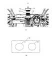
図9は、本発明の一実施例に従う、表示器によるACC制御をオンまたはオフの表示例を示す図である。図9(a)は、車室内での表示部73の位置を示す図である。図9(a)では、表示部73を、車室の中心線C上に位置するルームミラー72の下部に設置する場合と、フロントカバー部70の上に設置する場合を例示している。表示部73は、ナビゲーション装置13の表示部71の一部として組み込むあるいはその上部等に配置してもよい。なお、表示部73は、車室の中心付近に位置することが望ましい。その理由は、表示部73が車室の中心付近に位置することにより、運転者の視線方向が左右いずれに向かっていても、表示部73を運転者の視野内に入れることができるからである。 FIG. 9 is a diagram showing a display example of turning on or off the ACC control by the display according to one embodiment of the present invention. Fig.9 (a) is a figure which shows the position of the
図9(b)は、表示部73の拡大図である。表示部73は2つの点灯部731、732を有する。ACC制御のオンまたはオフに応じて、点灯部731、732の点灯形態が変化する。例えば、ACC制御オンで点灯部731が赤色に点灯あるいは点滅し、ACC制御オフで点灯部732が緑色に点灯あるいは点滅する、といった表示をおこなう。この点灯形態(色、点灯(点滅)時間等)は任意に設定することができる。同時に、スピーカー17からACC制御のオンまたはオフを音声によって報知してもよい。これにより、運転者に交通流判定結果に応じたACC制御のオンまたはオフを素早く知らしめることができ、運転者による渋滞回避あるいは解消のための運転への移行を促すことができる。 FIG. 9B is an enlarged view of the
図10は、本発明の一実施例に従う、渋滞予測のフローチャートである。なお、各ステップの詳細は既に説明した通りである。ステップS10において、車速センサ11によって自車両の加速度を検出する。並行して、ステップS11において、レーダ装置12からの出力信号に基づき自車両の周辺の車両との車間距離を検出する(図1のブロック34〜36)。ステップS12において、加速度スペクトル単回帰極大化をおこなう。具体的には、上述した傾き極大値を算出する(図1のブロック31〜33)。並行して、ステップS13において、共分散値特異化をおこなう。具体的には、上述した共分散最小値を算出する(図1のブロック37、38)。 FIG. 10 is a flowchart of traffic jam prediction according to one embodiment of the present invention. The details of each step are as described above. In step S10, the
ステップS14において、臨界領域のモデリングをおこなう。具体的には、上述した図8(b)で例示されるような相関マップを作成する(図1のブロック40)。ステップS15において、臨界領域が存在するか否かを判定する。臨界領域とは、上述した図7、図8(a)に例示される臨界領域の状態である。この判定がYesの場合、次のステップS16においてACC制御をオフに切り替える。ACC制御は停止される。 In step S14, the critical region is modeled. Specifically, a correlation map as illustrated in FIG. 8B is created (
ステップS15の判定がNoの場合、ステップS17において混合流が存在するか否かを判定する。この判定がYesの場合、次のステップS18においてACC制御をオンに切り替える。既に述べたACC制御が行われる。この判定がNoの場合はステップS12、S13に戻り以降のフローを繰り返す。 If the determination in step S15 is No, it is determined in step S17 whether a mixed flow exists. If this determination is Yes, the ACC control is turned on in the next step S18. The ACC control already described is performed. If this determination is No, the process returns to steps S12 and S13 and the subsequent flow is repeated.
以上、本発明の実施の形態について説明したが、本発明はこのような実施形態に限定されることはなく、本発明の趣旨を逸脱しない範囲において改変して用いることができる。 The embodiment of the present invention has been described above, but the present invention is not limited to such an embodiment, and can be modified and used without departing from the spirit of the present invention.
14 処理装置
51、53 加速度(パワー)スペクトル
52、54 単回帰直線
100 走行支援装置14
Claims (4)
Translated fromJapanese周辺の他車両を検出して検出信号を出力するレーダと、
プロセッサと記憶装置とを備える処理装置と、
を備え、
前記処理装置は、
自車両の走行制御を行うものであって、
前記検出信号に基づき前記他車両との車間距離を算出し、
前記センサが検出した自車両の加速度と、前記算出した車間距離とに基づき、自車両が走行する車線における交通流の状態を判定し、
前記判定した交通流の状態が、渋滞が発生する可能性が低い自由流の状態から車両の制動状態と加速状態が混合する混合流の状態へ移行する間に存在する臨界領域の状態であるときに、前記走行制御を切り替えるように構成されている、
車両の走行支援装置。A sensor for detecting the accelerationof the host vehicle;
A radar thatdetects other vehicles in the vicinityand outputs a detection signal ;
A processing device comprising a processor and a storage device;
With
The processor is
Which controls the running of the vehicle,
Calculating an inter-vehicle distance from the other vehicle based on the detection signal;
Based on the acceleration of the host vehicle detected by the sensor and the calculated inter-vehicle distance, the state of traffic flow in the lane in which the host vehicle travels is determined,
Whenthe state ofthe determined traffic flow, traffic congestion is the state of the critical region present during the transition from the state of free flow it is less likely to occur to the state of the mixed flow the braking state and the acceleration state of the vehicle are mixed to,and is configured to switchthe cruise control,
A vehicle travel support device.
自車両の加速度から得られるパワースペクトルの単回帰直線から傾き極大値の対数を算出し、
前記車間距離の分布を算出し、
前記分布の共分散の最小値の対数を算出し、
前記傾き極大値の対数と前記共分散の最小値の対数との相関マップを生成するよう構成され、
前記処理装置は、前記相関マップに基づいて前記交通流の状態を判定する、
請求項1に記載の車両の走行支援装置。The processing apparatus further includes:
Calculating the logarithm of the single regression line oret tilt-out maximum value of the power spectrum obtained from the acceleration ofthe vehicle,
Calculating the distributionof the inter-vehicle distance,
Calculating the logarithmof the minimum value ofthe covariance of the distribution,
Configured to generate a correlation map between thelogarithm of theslope maximum and the logarithm of the minimum covariance;
The processor determines the state of the traffic flowbased on the correlation map ;
The vehicle travel support apparatus accordingto claim1 .
前記走行制御の一部として自動低速走行制御を実行するものであって、
前記走行制御の切り替え時に前記自動走行制御をオン又はオフにする、
請求項1ないし3のいずれか一項に記載の車両の走行支援装置。The processing apparatus further includes:
Automatic low-speed running controlis executedas part of the running control,
Youto the travel control of switchingduring the automatic travel control on oroff,
The vehicle travel support apparatus according toany one of claims 1to 3 .
Priority Applications (1)
| Application Number | Priority Date | Filing Date | Title |
|---|---|---|---|
| JP2012548636AJP5511984B2 (en) | 2010-12-15 | 2011-12-09 | Vehicle travel support device |
Applications Claiming Priority (4)
| Application Number | Priority Date | Filing Date | Title |
|---|---|---|---|
| JP2010278752 | 2010-12-15 | ||
| JP2010278752 | 2010-12-15 | ||
| JP2012548636AJP5511984B2 (en) | 2010-12-15 | 2011-12-09 | Vehicle travel support device |
| PCT/JP2011/006878WO2012081208A1 (en) | 2010-12-15 | 2011-12-09 | Vehicular driving assist device |
Publications (2)
| Publication Number | Publication Date |
|---|---|
| JPWO2012081208A1 JPWO2012081208A1 (en) | 2014-05-22 |
| JP5511984B2true JP5511984B2 (en) | 2014-06-04 |
Family
ID=46244327
Family Applications (1)
| Application Number | Title | Priority Date | Filing Date |
|---|---|---|---|
| JP2012548636AExpired - Fee RelatedJP5511984B2 (en) | 2010-12-15 | 2011-12-09 | Vehicle travel support device |
Country Status (5)
| Country | Link |
|---|---|
| US (1) | US9031761B2 (en) |
| JP (1) | JP5511984B2 (en) |
| CN (1) | CN103249627B (en) |
| BR (1) | BR112013014736A2 (en) |
| WO (1) | WO2012081208A1 (en) |
Families Citing this family (34)
| Publication number | Priority date | Publication date | Assignee | Title |
|---|---|---|---|---|
| JP5501208B2 (en)* | 2010-12-15 | 2014-05-21 | 本田技研工業株式会社 | Driving support method |
| JP5667944B2 (en)* | 2011-08-11 | 2015-02-12 | 本田技研工業株式会社 | Driving support method for eliminating traffic on the server side |
| CN106573618B (en)* | 2014-08-11 | 2018-06-29 | 日产自动车株式会社 | The travel controlling system and method for vehicle |
| CN104494597A (en)* | 2014-12-10 | 2015-04-08 | 浙江吉利汽车研究院有限公司 | Self-adapted cruising control system |
| JP6202537B2 (en)* | 2015-04-14 | 2017-09-27 | 本田技研工業株式会社 | Driving support method, program, and driving support device |
| WO2017033215A1 (en) | 2015-08-27 | 2017-03-02 | 日本電気株式会社 | Traffic-congestion prevention system, traffic-congestion prevention method, and recording medium |
| US10093304B2 (en)* | 2015-09-11 | 2018-10-09 | Ford Global Technologies, Llc | Enhanced electric drive mode having predicted destinations to reduce engine starts |
| JP6365481B2 (en)* | 2015-09-23 | 2018-08-01 | トヨタ自動車株式会社 | Vehicle travel control device |
| US10532736B2 (en)* | 2015-11-06 | 2020-01-14 | Honda Motor Co., Ltd. | Vehicle travel control device |
| US10037696B2 (en)* | 2016-03-31 | 2018-07-31 | Delphi Technologies, Inc. | Cooperative automated vehicle system |
| US9701307B1 (en) | 2016-04-11 | 2017-07-11 | David E. Newman | Systems and methods for hazard mitigation |
| US10062288B2 (en)* | 2016-07-29 | 2018-08-28 | GM Global Technology Operations LLC | Systems and methods for autonomous driving merging management |
| JP6426674B2 (en)* | 2016-09-29 | 2018-11-21 | 株式会社東芝 | Road traffic situation estimation system and road traffic situation estimation method |
| US10163339B2 (en)* | 2016-12-13 | 2018-12-25 | Sap Se | Monitoring traffic congestion |
| US10449956B2 (en)* | 2017-01-18 | 2019-10-22 | Ford Global Technologies, Llc | Object tracking by unsupervised learning |
| US10908607B2 (en)* | 2017-11-30 | 2021-02-02 | Ford Global Technologies, Llc | Enhanced traffic jam assist |
| CN108510776A (en)* | 2018-05-24 | 2018-09-07 | 深圳市华慧品牌管理有限公司 | Road congestion prediction technique based on automobile data recorder and device |
| US10745007B2 (en)* | 2018-06-08 | 2020-08-18 | Denso International America, Inc. | Collision avoidance systems and methods |
| US10816635B1 (en) | 2018-12-20 | 2020-10-27 | Autonomous Roadway Intelligence, Llc | Autonomous vehicle localization system |
| US10820349B2 (en) | 2018-12-20 | 2020-10-27 | Autonomous Roadway Intelligence, Llc | Wireless message collision avoidance with high throughput |
| JP6859374B2 (en)* | 2019-01-11 | 2021-04-14 | 本田技研工業株式会社 | Predictors, predictors, and programs |
| JP7268464B2 (en)* | 2019-04-23 | 2023-05-08 | 株式会社デンソー | vehicle controller |
| US10820182B1 (en) | 2019-06-13 | 2020-10-27 | David E. Newman | Wireless protocols for emergency message transmission |
| US10713950B1 (en) | 2019-06-13 | 2020-07-14 | Autonomous Roadway Intelligence, Llc | Rapid wireless communication for vehicle collision mitigation |
| US10939471B2 (en) | 2019-06-13 | 2021-03-02 | David E. Newman | Managed transmission of wireless DAT messages |
| KR102821660B1 (en)* | 2019-08-16 | 2025-06-16 | 엘지전자 주식회사 | Apparatus and method for changing traffic line of autonomous vehicle |
| EP3790295B1 (en)* | 2019-09-09 | 2024-05-29 | Volkswagen AG | Method, computer program, and apparatus for determining a minimum inter-vehicular distance for a platoon, vehicle, traffic control entity |
| WO2021149846A1 (en)* | 2020-01-22 | 2021-07-29 | 엘지전자 주식회사 | Route providing device and route providing method therefor |
| KR20220055335A (en)* | 2020-10-26 | 2022-05-03 | 현대자동차주식회사 | Traffic information prediction apparatus and prediction method using the same |
| US11206169B1 (en) | 2020-11-13 | 2021-12-21 | Ultralogic 5G, Llc | Asymmetric modulation for high-reliability 5G communications |
| US20220183068A1 (en) | 2020-12-04 | 2022-06-09 | David E. Newman | Rapid Uplink Access by Parallel Signaling on a 5G Random-Access Channel |
| CN113401123B (en)* | 2021-05-24 | 2022-04-01 | 吉林大学 | Vehicle predictive cruise parameter self-tuning control system based on driving mode information |
| CN113920727B (en)* | 2021-10-08 | 2023-11-07 | 温州大学 | Prediction method and system for road congestion caused by construction |
| US20240157937A1 (en)* | 2022-10-31 | 2024-05-16 | Nissan North America, Inc. | Vehicle on-board unit |
Citations (4)
| Publication number | Priority date | Publication date | Assignee | Title |
|---|---|---|---|---|
| JP2004233191A (en)* | 2003-01-30 | 2004-08-19 | Mazda Motor Corp | Navigation system for vehicle, computer program for navigation for vehicle, and navigation apparatus for vehicle |
| JP2007219743A (en)* | 2006-02-15 | 2007-08-30 | Denso Corp | Traveling control system for automobile |
| JP2009262862A (en)* | 2008-04-28 | 2009-11-12 | Toyota Motor Corp | Traveling controller and traveling control method |
| JP2010036862A (en)* | 2008-08-08 | 2010-02-18 | Toyota Motor Corp | Travel control device and travel control system |
Family Cites Families (1)
| Publication number | Priority date | Publication date | Assignee | Title |
|---|---|---|---|---|
| DE10218017A1 (en)* | 2002-04-23 | 2003-11-06 | Bosch Gmbh Robert | Method for speed and distance control in motor vehicles |
- 2011
- 2011-12-09JPJP2012548636Apatent/JP5511984B2/ennot_activeExpired - Fee Related
- 2011-12-09USUS13/993,607patent/US9031761B2/enactiveActive
- 2011-12-09BRBR112013014736Apatent/BR112013014736A2/ennot_activeApplication Discontinuation
- 2011-12-09CNCN201180058985.8Apatent/CN103249627B/enactiveActive
- 2011-12-09WOPCT/JP2011/006878patent/WO2012081208A1/enactiveApplication Filing
Patent Citations (4)
| Publication number | Priority date | Publication date | Assignee | Title |
|---|---|---|---|---|
| JP2004233191A (en)* | 2003-01-30 | 2004-08-19 | Mazda Motor Corp | Navigation system for vehicle, computer program for navigation for vehicle, and navigation apparatus for vehicle |
| JP2007219743A (en)* | 2006-02-15 | 2007-08-30 | Denso Corp | Traveling control system for automobile |
| JP2009262862A (en)* | 2008-04-28 | 2009-11-12 | Toyota Motor Corp | Traveling controller and traveling control method |
| JP2010036862A (en)* | 2008-08-08 | 2010-02-18 | Toyota Motor Corp | Travel control device and travel control system |
Also Published As
| Publication number | Publication date |
|---|---|
| JPWO2012081208A1 (en) | 2014-05-22 |
| US9031761B2 (en) | 2015-05-12 |
| CN103249627A (en) | 2013-08-14 |
| CN103249627B (en) | 2016-02-24 |
| US20130268174A1 (en) | 2013-10-10 |
| WO2012081208A1 (en) | 2012-06-21 |
| BR112013014736A2 (en) | 2016-10-04 |
Similar Documents
| Publication | Publication Date | Title |
|---|---|---|
| JP5511984B2 (en) | Vehicle travel support device | |
| JP5555778B2 (en) | Traffic jam prediction method | |
| JP6318864B2 (en) | Driving assistance device | |
| JP5481557B2 (en) | Traffic jam prediction method | |
| JP2020119517A (en) | Method for assisting driver, driver assistance system, and vehicle having such driver assistance system | |
| JP5501209B2 (en) | Vehicle travel support device | |
| JP5462945B2 (en) | Congestion prediction display method | |
| JP5627531B2 (en) | Driving assistance device | |
| CN106338988A (en) | Control system of automated driving vehicle | |
| JP5570961B2 (en) | How to display traffic sign | |
| JP6711329B2 (en) | Driving support device | |
| US12036988B2 (en) | Method and control unit for operating an adaptive cruise controller | |
| JP2010097261A (en) | Vehicle route prediction device | |
| US20200298885A1 (en) | Vehicle control apparatus, vehicle control method, vehicle, and storage medium | |
| CN112441013B (en) | Map-based overspeed avoidance of vehicles | |
| JP5909144B2 (en) | Vehicle group elimination system | |
| JP7447870B2 (en) | Information processing server, information processing server processing method, program | |
| JP2012117938A (en) | Information processor for vehicle | |
| JP5450365B2 (en) | Driving support system | |
| JP7609110B2 (en) | Vehicle control device, vehicle control method, and vehicle control computer program | |
| JP2019026183A (en) | Vehicle control device, speed control method | |
| JP5501208B2 (en) | Driving support method | |
| US11807274B2 (en) | L4 auto-emergency light system for future harsh brake | |
| JP2013104815A (en) | Navigation device | |
| JP5909401B2 (en) | Traffic jam prediction method |
Legal Events
| Date | Code | Title | Description |
|---|---|---|---|
| TRDD | Decision of grant or rejection written | ||
| A01 | Written decision to grant a patent or to grant a registration (utility model) | Free format text:JAPANESE INTERMEDIATE CODE: A01 Effective date:20140311 | |
| A61 | First payment of annual fees (during grant procedure) | Free format text:JAPANESE INTERMEDIATE CODE: A61 Effective date:20140325 | |
| R150 | Certificate of patent or registration of utility model | Ref document number:5511984 Country of ref document:JP Free format text:JAPANESE INTERMEDIATE CODE: R150 | |
| LAPS | Cancellation because of no payment of annual fees |