JP5511483B2 - Information processing apparatus, control method, and program - Google Patents
Information processing apparatus, control method, and programDownload PDFInfo
- Publication number
- JP5511483B2 JP5511483B2JP2010097420AJP2010097420AJP5511483B2JP 5511483 B2JP5511483 B2JP 5511483B2JP 2010097420 AJP2010097420 AJP 2010097420AJP 2010097420 AJP2010097420 AJP 2010097420AJP 5511483 B2JP5511483 B2JP 5511483B2
- Authority
- JP
- Japan
- Prior art keywords
- link
- information
- unit
- peripheral device
- processing apparatus
- Prior art date
- Legal status (The legal status is an assumption and is not a legal conclusion. Google has not performed a legal analysis and makes no representation as to the accuracy of the status listed.)
- Active
Links
Images


Classifications
- G—PHYSICS
- G06—COMPUTING OR CALCULATING; COUNTING
- G06F—ELECTRIC DIGITAL DATA PROCESSING
- G06F3/00—Input arrangements for transferring data to be processed into a form capable of being handled by the computer; Output arrangements for transferring data from processing unit to output unit, e.g. interface arrangements
- G06F3/12—Digital output to print unit, e.g. line printer, chain printer
- G06F3/1201—Dedicated interfaces to print systems
- G06F3/1202—Dedicated interfaces to print systems specifically adapted to achieve a particular effect
- G06F3/1203—Improving or facilitating administration, e.g. print management
- G06F3/1204—Improving or facilitating administration, e.g. print management resulting in reduced user or operator actions, e.g. presetting, automatic actions, using hardware token storing data
- G—PHYSICS
- G06—COMPUTING OR CALCULATING; COUNTING
- G06F—ELECTRIC DIGITAL DATA PROCESSING
- G06F21/00—Security arrangements for protecting computers, components thereof, programs or data against unauthorised activity
- G06F21/60—Protecting data
- G06F21/606—Protecting data by securing the transmission between two devices or processes
- G06F21/608—Secure printing
- G—PHYSICS
- G06—COMPUTING OR CALCULATING; COUNTING
- G06F—ELECTRIC DIGITAL DATA PROCESSING
- G06F21/00—Security arrangements for protecting computers, components thereof, programs or data against unauthorised activity
- G06F21/60—Protecting data
- G06F21/64—Protecting data integrity, e.g. using checksums, certificates or signatures
- G—PHYSICS
- G06—COMPUTING OR CALCULATING; COUNTING
- G06F—ELECTRIC DIGITAL DATA PROCESSING
- G06F3/00—Input arrangements for transferring data to be processed into a form capable of being handled by the computer; Output arrangements for transferring data from processing unit to output unit, e.g. interface arrangements
- G06F3/12—Digital output to print unit, e.g. line printer, chain printer
- G06F3/1201—Dedicated interfaces to print systems
- G06F3/1223—Dedicated interfaces to print systems specifically adapted to use a particular technique
- G06F3/1224—Client or server resources management
- G06F3/1225—Software update, e.g. print driver, modules, plug-ins, fonts
- G—PHYSICS
- G06—COMPUTING OR CALCULATING; COUNTING
- G06F—ELECTRIC DIGITAL DATA PROCESSING
- G06F3/00—Input arrangements for transferring data to be processed into a form capable of being handled by the computer; Output arrangements for transferring data from processing unit to output unit, e.g. interface arrangements
- G06F3/12—Digital output to print unit, e.g. line printer, chain printer
- G06F3/1201—Dedicated interfaces to print systems
- G06F3/1278—Dedicated interfaces to print systems specifically adapted to adopt a particular infrastructure
- G06F3/1285—Remote printer device, e.g. being remote from client or server
- G—PHYSICS
- G06—COMPUTING OR CALCULATING; COUNTING
- G06F—ELECTRIC DIGITAL DATA PROCESSING
- G06F8/00—Arrangements for software engineering
- G06F8/60—Software deployment
- G06F8/61—Installation
- G—PHYSICS
- G06—COMPUTING OR CALCULATING; COUNTING
- G06F—ELECTRIC DIGITAL DATA PROCESSING
- G06F9/00—Arrangements for program control, e.g. control units
- G06F9/06—Arrangements for program control, e.g. control units using stored programs, i.e. using an internal store of processing equipment to receive or retain programs
- G06F9/44—Arrangements for executing specific programs
- G06F9/4401—Bootstrapping
- G06F9/4411—Configuring for operating with peripheral devices; Loading of device drivers
- H—ELECTRICITY
- H04—ELECTRIC COMMUNICATION TECHNIQUE
- H04N—PICTORIAL COMMUNICATION, e.g. TELEVISION
- H04N1/00—Scanning, transmission or reproduction of documents or the like, e.g. facsimile transmission; Details thereof
- H04N1/00127—Connection or combination of a still picture apparatus with another apparatus, e.g. for storage, processing or transmission of still picture signals or of information associated with a still picture
- H04N1/00204—Connection or combination of a still picture apparatus with another apparatus, e.g. for storage, processing or transmission of still picture signals or of information associated with a still picture with a digital computer or a digital computer system, e.g. an internet server
- H04N1/00209—Transmitting or receiving image data, e.g. facsimile data, via a computer, e.g. using e-mail, a computer network, the internet, I-fax
- H04N1/00222—Transmitting or receiving image data, e.g. facsimile data, via a computer, e.g. using e-mail, a computer network, the internet, I-fax details of image data generation or reproduction, e.g. scan-to-email or network printing
- H—ELECTRICITY
- H04—ELECTRIC COMMUNICATION TECHNIQUE
- H04N—PICTORIAL COMMUNICATION, e.g. TELEVISION
- H04N1/00—Scanning, transmission or reproduction of documents or the like, e.g. facsimile transmission; Details thereof
- H04N1/00127—Connection or combination of a still picture apparatus with another apparatus, e.g. for storage, processing or transmission of still picture signals or of information associated with a still picture
- H04N1/00204—Connection or combination of a still picture apparatus with another apparatus, e.g. for storage, processing or transmission of still picture signals or of information associated with a still picture with a digital computer or a digital computer system, e.g. an internet server
- H04N1/00244—Connection or combination of a still picture apparatus with another apparatus, e.g. for storage, processing or transmission of still picture signals or of information associated with a still picture with a digital computer or a digital computer system, e.g. an internet server with a server, e.g. an internet server
- H—ELECTRICITY
- H04—ELECTRIC COMMUNICATION TECHNIQUE
- H04N—PICTORIAL COMMUNICATION, e.g. TELEVISION
- H04N1/00—Scanning, transmission or reproduction of documents or the like, e.g. facsimile transmission; Details thereof
- H04N1/0035—User-machine interface; Control console
- H04N1/00405—Output means
- H04N1/00408—Display of information to the user, e.g. menus
- H04N1/00464—Display of information to the user, e.g. menus using browsers, i.e. interfaces based on mark-up languages
- G—PHYSICS
- G06—COMPUTING OR CALCULATING; COUNTING
- G06F—ELECTRIC DIGITAL DATA PROCESSING
- G06F21/00—Security arrangements for protecting computers, components thereof, programs or data against unauthorised activity
- G06F21/30—Authentication, i.e. establishing the identity or authorisation of security principals
- G06F21/44—Program or device authentication
- H—ELECTRICITY
- H04—ELECTRIC COMMUNICATION TECHNIQUE
- H04N—PICTORIAL COMMUNICATION, e.g. TELEVISION
- H04N2201/00—Indexing scheme relating to scanning, transmission or reproduction of documents or the like, and to details thereof
- H04N2201/0077—Types of the still picture apparatus
- H04N2201/0094—Multifunctional device, i.e. a device capable of all of reading, reproducing, copying, facsimile transception, file transception
Landscapes
- Engineering & Computer Science (AREA)
- Theoretical Computer Science (AREA)
- General Engineering & Computer Science (AREA)
- General Physics & Mathematics (AREA)
- Software Systems (AREA)
- Physics & Mathematics (AREA)
- Human Computer Interaction (AREA)
- Computer Security & Cryptography (AREA)
- Signal Processing (AREA)
- Multimedia (AREA)
- Computing Systems (AREA)
- Health & Medical Sciences (AREA)
- Bioethics (AREA)
- General Health & Medical Sciences (AREA)
- Computer Hardware Design (AREA)
- User Interface Of Digital Computer (AREA)
- Accessory Devices And Overall Control Thereof (AREA)
- Information Transfer Between Computers (AREA)
- Stored Programmes (AREA)
- Computer And Data Communications (AREA)
Description
Translated fromJapanese本発明は、周辺機器を管理する情報処理装置、情報処理方法、及びプログラムに関する。 The present invention relates to an information processing apparatus, an information processing method, and a program for managing peripheral devices.
近年、USB、Ethernet(登録商標)、無線LAN等の様々なインタフェースを利用して、パーソナルコンピュータ(以降、PCと略す場合がある)に周辺機器を接続し、自宅やオフィスで様々な形態でこのような周辺機器制御システムが有効に活用されている。 In recent years, peripheral devices are connected to a personal computer (hereinafter may be abbreviated as a PC) using various interfaces such as USB, Ethernet (registered trademark), wireless LAN, etc. Such peripheral device control systems are effectively utilized.
米国マイクロソフト社のWindows(登録商標)7では、PCに接続された周辺機器を管理する機能であるDevice Stage(登録商標)を有する。これは、PCに接続された機器を表示するウィンドウであるDevices and Printersと各機器の固有のアプリケーションやサービスへのリンク機能を有する。Devices and Printersの画面(図7(a))は、Windowsの「スタートメニュー」から表示することができる。Devices and Printers画面からはさらに各機器のDevice Stage画面(図7(b))を開くことができる。Device Stageではビジュアルな画面を提供でき、ユーザが簡単に機器に関連する機能やサービスにアクセスすることができるようになる。 Windows (registered trademark) 7 of Microsoft Corporation of America has Device Stage (registered trademark) which is a function for managing peripheral devices connected to the PC. This has Devices and Printers, which are windows for displaying devices connected to the PC, and a link function to a specific application or service of each device. The Devices and Printers screen (FIG. 7A) can be displayed from the “Start Menu” of Windows. From the Devices and Printers screen, the Device Stage screen (FIG. 7B) of each device can be opened. In Device Stage, a visual screen can be provided, and the user can easily access functions and services related to the device.
周辺機器メーカーは、自社の機器をDevice Stageに対応するために、デバイスメタデータパッケージと呼ばれる画面情報が記載されたファイルを作成する。デバイスメタデータパッケージは、インターネット等を経由してPCにインストールされ、一旦インストールされると、Devices and Printers画面におよびDevice Stage画面に、機器に応じた画面が表示される。このとき、デバイスメタデータパッケージは、記載された内容が改竄されることを防止するため、電子署名が施された状態でPCにインストールされる。 A peripheral device manufacturer creates a file in which screen information called a device metadata package is described in order to support the device of its own device in Device Stage. The device metadata package is installed on the PC via the Internet or the like, and once installed, a screen corresponding to the device is displayed on the Devices and Printers screen and the Device Stage screen. At this time, the device metadata package is installed in the PC in a state where an electronic signature is applied in order to prevent the described contents from being falsified.
プリンタを例に挙げると、写真やドキュメントを開いて表示・印刷するようなアプリケーションへのリンクをDevice Stage画面上から提供することが考えられる。また、情報処理装置や周辺機器をインターネットに接続し、インターネットを利用した様々なオンラインサービスも提供されている。例えば、メーカーがインターネット上で提供するサポートサイト等へのリンクをDevice Stage画面上に設けることで、ユーザが簡単に機器に関連するサイトにアクセスできるようにするといった活用例も挙げられる。 Taking a printer as an example, it is conceivable to provide a link to an application that opens, displays, and prints a photo or document from the Device Stage screen. In addition, various online services using the Internet by connecting information processing apparatuses and peripheral devices to the Internet are also provided. For example, there is a utilization example in which a user can easily access a site related to a device by providing a link to a support site provided by the manufacturer on the Internet on the Device Stage screen.
一方、複合機を使用する大規模な企業においては、複合機の利用方法のガイダンスや使用する際の注意事項等の情報をイントラネットのWebページを企業内に公開しているケースがある。このようなユーザ環境において、例えば、これらのイントラネットのWebページへのリンクをDevice Stage画面上に追加して、イントラネットサイトへユーザがより簡単にアクセスできるようにするといった運用が考えられる。このように画面をカスタマイズする手段としては、従来から特許文献1に示すような技術が存在する。 On the other hand, in a large-scale company that uses a multifunction device, there are cases where information such as guidance on how to use the multifunction device and precautions when using it are made public on the intranet Web page. In such a user environment, for example, an operation of adding a link to the intranet Web page on the Device Stage screen so that the user can more easily access the intranet site can be considered. As means for customizing the screen in this way, there is a technique as shown in
特許文献1に記載の従来の画面カスタマイズ手段は、画面情報を直接編集してカスタマイズする形式が採用されている。Device Stageにおいては、画面情報が含まれたデバイスメタデータパッケージが電子署名された状態でインストールされるため、直接画面情報を編集することはできない。また、特許文献1に示す方法では、Device Stageの画面情報をカスタマイズすることができない。そのため、ユーザ環境に応じたDevice Stage画面を作成するには、デバイスメタデータパッケージを作成しなおす必要がある。ユーザ環境毎にデバイスメタデータパッケージを作成すると、メーカーの負担が大きいという課題があった。 The conventional screen customization means described in
上記課題を解決するために、本発明は以下の構成を有する。周辺機器に接続され、前記周辺機器を管理する周辺機器管理部を有する情報処理装置であって、前記周辺機器を管理する機能を示す表示を制御するための情報および機能それぞれを提供するリンク先を示すリンク情報が定義され、改竄の有無を確認するために電子署名された情報である周辺装置管理機能制御情報を記憶する記憶手段と、前記周辺機器管理部からのリクエストを受信するリクエスト受信手段と、前記リクエスト受信手段にて受信したリクエストに応じて実行される、前記周辺装置管理機能制御情報に含まれるリンク情報とは別のリンク情報を管理するリンク管理手段と、前記周辺装置管理機能制御情報に含まれるリンク情報もしくは前記リンク管理手段により管理された前記別のリンク情報を用い、前記リクエスト受信手段にて受信したリクエストに基づいてリンク先を決定し、決定されたリンク先へのリンク処理を実行する実行手段とを有する。 In order to solve the above problems, the present invention has the following configuration. An information processing apparatus connected to a peripheral device and having a peripheral device management unit for managing the peripheral device, the link destination providing information and a function for controlling a display indicating a function for managing the peripheral device. Storage means for storing peripheral device management function control information, which is information digitally signed to confirm whether or not tampering is defined, and request reception means for receiving a request from the peripheral device management unit Link management means for managing link information different from link information included in the peripheral device management function control information, which is executed in response to the request received by the request receiving means, and the peripheral device management function control information To the request receiving means using the link information included in the link information or the other link information managed by the link managing means. It determines the destination based on the received request, and an execution means for executing link processing to the determined link destination.
本発明により、表示に用いるデバイスメタデータパッケージの内容を変更することなく、ユーザが画面表示に任意のリンクを追加できる。このことから、ユーザ環境毎にデバイスメタデータパッケージを作成する必要がないため、カスタマイズによるメーカーの負荷が軽減される。さらに、プリンタドライバを介してカスタムリンク情報を追加するので、追加のアプリケーションを必要とせず、安全なカスタマイズ手段を提供できる。 According to the present invention, the user can add an arbitrary link to the screen display without changing the contents of the device metadata package used for display. This eliminates the need to create a device metadata package for each user environment, thereby reducing the burden on the manufacturer due to customization. Furthermore, since the custom link information is added via the printer driver, a safe customization means can be provided without requiring an additional application.
<第1の実施形態>
[ハードウェア構成]
以下、本発明の実施形態を、図面を参照して説明する。図1は本発明に係る情報処理装置及び周辺機器からなる周辺機器管理システムの一実施形態におけるシステムの構成部分を表すブロック図である。図1における情報処理装置200、203、300は、一般的なPCで構成される。PC300は図2で後述するようなハードウェアで構成され、OS(Operating System)として米国マイクロソフト社のWindows7と同等のOSがインストールされている。PC200、PC203、PC300はそれぞれEthernet(登録商標)で構成されるネットワーク205、206に接続されている。プリンタ150は、本発明における周辺機器の一例としている。ここでプリンタ150はABC社製のKmmnというモデル名のプリンタである。尚、本発明における周辺機器としては、複写機、ファクシミリ、スキャナ、デジタルカメラ、及びこれらの複合機能を備える装置等であってもよい。<First Embodiment>
[Hardware configuration]
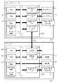
Embodiments of the present invention will be described below with reference to the drawings. FIG. 1 is a block diagram showing components of a system in an embodiment of a peripheral device management system including an information processing apparatus and peripheral devices according to the present invention. The
プリンタ150は、図2で後述するようなハードウェアで構成され、PC300とネットワーク205を介して接続されており、互いに双方向通信が可能である。周辺機器管理部であるデバイス管理アプリケーション80は、Windows用の実行可能形式のファイル(*.EXE)で構成される。本発明の一例として、デバイス管理アプリケーション80は図7(a)、図5(b)に示すようなデバイス管理画面を表示する機能を有する。プリンタドライバ50はプリンタ150を制御する。ネットワーク205は、プリンタ150を使用するユーザのオフィス等に構築されたLAN(Local Area Network)である。ネットワーク206はABC社内に構築されたLANである。 The
ネットワーク206に接続されているPC200はWebサーバの機能を持つWebサーバ201を備えており、インターネットを介してABC社のWebサイトを提供している。Webサーバ201に格納された202は図8で後述するデバイスメタデータパッケージであり、Webサーバ201から配布される。本実施形態において、デバイスメタデータパッケージ202はプリンタ150の製造元であるABC社によって作成され、作成時に電子署名が施された状態でWebサーバ201に格納されている。また、ネットワーク205に接続されたPC203もWebサーバ機能を持つWebサーバ204を備え、ユーザ環境の社内イントラネットのWebサイトを提供している。 The
図2は、本実施形態のコンピュータを含むプリンタ制御システムの構成を説明するブロック図である。図2において、PC300はホストコンピュータで、ROM3のプログラム用ROMあるいは外部メモリ11に記憶された文書処理プログラム等に基づいて図形、イメージ、文字、表(表計算等を含む)等が混在した文書処理を実行するCPU1を備える。さらに、システムバス4に接続される各デバイスをCPU1が総括的に制御する。 FIG. 2 is a block diagram illustrating a configuration of a printer control system including a computer according to the present embodiment. In FIG. 2, a
また、このROM3のプログラム用ROMあるいは外部メモリ11には、CPU1の制御プログラムであるオペレーティングシステムプログラム(以下OS)等を記憶する。ROM3のフォント用ROMあるいは外部メモリ11には上記文書処理の際に使用するフォントデータ等を記憶し、ROM3のデータ用ROMあるいは外部メモリ11には上記文書処理等を行う際に使用する各種データを記憶する。 Further, an operating system program (hereinafter referred to as OS) which is a control program of the
RAM2は、CPU1の主メモリ、ワークエリア等として機能する。キーボードI/F5は、キーボード9やポインティングデバイス(不図示)からのキー入力を制御する。ディプレイI/F6は、ディスプレイ10の表示を制御する。外部メモリI/F7は、ハードディスク(HD)、フロッピー(登録商標)ディスク(FD)等の外部メモリ11とのアクセスを制御する。外部メモリ11は、ブートプログラム、各種のアプリケーション、フォントデータ、ユーザファイル、編集ファイル、プリンタドライバ等を記憶する。 The
プリンタI/F8は、所定の双方向性インタフェース22を介してプリンタ150に接続されて、プリンタ150との通信制御処理を実行する。なお、CPU1は、例えばRAM2上に設定された表示情報RAMへのアウトラインフォントの展開(ラスタライズ)処理を実行し、ディスプレイ10上でのWYSIWYGを可能としている。 The printer I /
また、CPU1は、ディスプレイ10上のマウスカーソル(不図示)等で指示されたコマンドに基づいて登録された種々のウィンドウを開き、種々のデータ処理を実行する。ユーザは印刷を実行する際、印刷の設定に関するウィンドウを開き、プリンタの設定や、印刷モードの選択を含むプリンタドライバに対する印刷処理方法の設定を行える。 Further, the
プリンタ150において、CPU12は制御プログラム等に基づいてシステムバス15に接続される印刷部(プリンタエンジン)19に出力情報としての画像信号を出力する。なお、制御プログラムはROM14のプログラム用ROMや外部メモリ21等に記憶される。 In the
また、このROM14のプログラムROMには、CPU12の制御プログラム等を記憶する。ROM14のフォント用ROMには上記出力情報を生成する際に使用するフォントデータ等を記憶する。ROM14のデータ用ROMにはハードディスク等の外部メモリ21がないプリンタの場合には、ホストコンピュータ上で利用される情報等を記憶している。 Further, the control program of the
CPU12は入力部16を介してPC300との通信処理が可能となっており、プリンタ内の情報等をPC300に通知可能に構成されている。RAM13は、CPU12の主メモリ、ワークエリア等として機能し、増設ポート(不図示)に接続されるオプションRAMによりメモリ容量を拡張することができるように構成されている。なお、RAM13は、出力情報展開領域、環境データ格納領域、NVRAM等に用いられる。前述したハードディスク(HD)、ICカード等の外部メモリ21は、メモリコントローラ(MC)によりアクセスを制御される。 The
外部メモリ21は、オプションとして接続され、フォントデータ、エミュレーションプログラム、フォームデータ等を記憶する。また、操作部20には前述した操作パネルで操作のためのスイッチおよびLED表示器等が配されている。また、前述した外部メモリは1個に限らず、少なくとも1個以上備え、内蔵フォントに加えてオプションフォントカード、言語系の異なるプリンタ制御言語を解釈するプログラムを格納した外部メモリを複数接続できるように構成されていてもよい。さらに、NVRAM(不図示)を有し、操作部20からのプリンタモード設定情報を記憶するようにしてもよい。 The
[ソフトウェア構成]
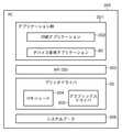
図3はPCのソフトウェア構成を表す図である。アプリケーション群301、API/DDI303、プリンタドライバ50、およびシステムスプーラ306は、実行される場合にOSやそのモジュールを利用するモジュールによってRAM2にロードされ実行されるプログラムモジュールである。Software configuration
FIG. 3 is a diagram showing the software configuration of the PC. The
アプリケーション群301は、デバイス管理アプリケーション80、印刷アプリケーション302等から構成される。デバイス管理アプリケーション80はOSに標準で同梱されており、印刷アプリケーション302は印刷処理を実行可能なアプリケーションである。デバイス管理アプリケーション80は、図7(a)、図7(b)を用いて後述するDevices and Printersフォルダ700やデバイス管理画面702を管理・実行する。API/DDI303は、Application Programing Interface(API)、Device Driver Interface(DDI)から構成される。 The
外部メモリ11に保存されている印刷アプリケーション302はRAM2にロードされて実行される。この印刷アプリケーション302からプリンタ150に対して印刷を行う際には、RAM2に読み込まれ実行可能となっているAPI/DDI303を利用して、印刷の設定および出力(描画)を行う。プリンタドライバ50は、ユーザインタフェースの提供及び制御を行うUIモジュール304と、印刷アプリケーション302の描画命令をプリンタの制御コマンドに変換するグラフィックスドライバ305から構成される。API/DDI303は、印刷機器ごとに用意されたプリンタドライバ50を同様に外部メモリ11からRAM2にロードし、印刷アプリケーション302の出力をプリンタドライバ50を用いてプリンタの制御コマンドに変換する。変換されたプリンタ制御コマンドは、OSによってRAM2にロードされたシステムスプーラ306を経て双方向性インタフェース22経由でプリンタ150へ出力される仕組みとなっている。 The print application 302 stored in the
図7(a)はDevices and Printersフォルダを表す図である。図7(a)において、Devices and Printersフォルダ700は、PC300上に表示され、PC300で利用できる状態のプリンタやFAXがインストールされたドライバ毎にこの中に表示される。 FIG. 7A shows the Devices and Printers folder. In FIG. 7A, a Devices and
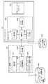
図4にはデバイス管理アプリケーション80とプリンタドライバ50のソフトウェア構成図を示す。デバイス管理アプリケーション80は、表示部401、デバイス管理制御部402、デバイスメタデータパッケージ読取り部403、リンク実行部404からなる。デバイスメタデータパッケージ格納部405には、図6のS604で外部メモリ11内の所定の位置に保存されたデバイスメタデータパッケージ800が保持されている。周辺装置管理機能制御情報であるデバイスメタデータパッケージ800に関しては、図8を用いて後述する。 FIG. 4 shows a software configuration diagram of the
プリンタドライバ50は、制御部406、UI表示部407、リンク管理部408、リンク実行部409、リンク情報保存部410からなる。リンク情報保存部410は、外部メモリ11など不揮発性の記憶領域に情報が保持され、デバイス管理アプリケーション80およびプリンタドライバ50の双方から読取り可能な領域である。 The
[プリンタドライバ50のインストール処理]
図5はプリンタ150接続時の処理を表すフローチャートである。図5のフローに係るプログラムは、PC300の外部メモリ11に記憶されており、RAM2に読み出され、CPU1により実行される。本実施形態においては、プリンタがネットワークを介してPCと接続されている場合について説明するが、USB等のインタフェースで接続されていてもよく、特に接続形態は限定しない。[Installation process of printer driver 50]
FIG. 5 is a flowchart showing processing when the
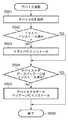
まず、例えば、WSD(Web Services on Devices)などのプロトコルを用いて、プリンタ150がネットワーク205を介してPC300に接続される。そして、デバイス管理アプリケーション80がプリンタ150からデバイスIDを取得する(S501)。 First, for example, the
デバイスIDは、例えば「MFG:ABC;MDL:Kmmn;CLS:PRINTER;CMD:K4;DES:ABC Kmmn;」のような文字列で表される。ここでのデバイスIDは、次の情報を表す構成を有する。
製造元(MFG:):ABC
モデル(MDL:):Kmmn
クラス(CLS:):PRINTER
コマンド(CMD:):K4(ABC社プライベートの印刷制御用コマンド)
ディスクリプション(DES:):ABC KmmnThe device ID is represented by a character string such as “MFG: ABC; MDL: Kmmn; CLS: PRINTER; CMD: K4; DES: ABC Kmmn;”. The device ID here has a configuration representing the following information.
Manufacturer (MFG :): ABC
Model (MDL :): Kmmn
Class (CLS :): PRINTER
Command (CMD :): K4 (ABC company private print control command)
Description (DES :): ABC Kmmn
次に、デバイス管理アプリケーション80は、プリンタドライバ50が既にインストール済みか否かを判定する(S502)。S502でインストールされていないと判定された場合(S502にてNO)、デバイス管理アプリケーション80がプリンタドライバ50をインストールする(S503)。一方、S502において、プリンタドライバ50が既にインストールされていると判定された場合(S502にてYES)は、そのままS504へ進む。 Next, the
次に、デバイス管理アプリケーション80がデバイスメタデータパッケージ(図8)がPC300上にインストール済みか否かを判定する(S504)。S504において、デバイス管理アプリケーション80は、プリンタ150に対応したデバイスメタデータパッケージがインストール済みか否かを、デバイスIDに含まれる製造元(MFG:)、モデル(MDL:)情報を元に判定する。S504でインストールされていないと判定された場合(S504にてNO)、図6を用いて後述するデバイスメタデータパッケージのインストールの処理を実行し(S505)、処理を終了する。また、S504において、デバイスメタデータパッケージが既にインストールされていると判定された場合(S504にてYES)はそのまま処理を終了する。 Next, the
プリンタドライバ50およびデバイスメタデータパッケージが正しくインストールされると、図7(a)に示すDevices and Printersフォルダ700にプリンタ701が登録された状態となる。 When the
[デバイスメタデータパッケージのインストール処理]
図6は、S505において実行されるデバイスメタデータパッケージのインストールの処理を表すフローチャートである。図6のフローに係るプログラムは、外部メモリ11に記憶されており、RAM2に読み出され、CPU1により実行される。[Device metadata package installation process]
FIG. 6 is a flowchart showing the device metadata package installation process executed in S505. The program according to the flow of FIG. 6 is stored in the
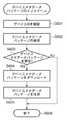
図5のS505において、デバイスメタデータパッケージのインストールの処理が実行されると、デバイス管理アプリケーション80が図6の処理を開始する。まず、デバイス管理アプリケーション80がネットワーク205を介して接続されているプリンタ150のデバイスIDを確認する(S601)。このデバイスIDに含まれている製造元(MFG:)、モデル(MDL:)の情報をもとに、デバイス管理アプリケーション80がプリンタ150用のデバイスメタデータパッケージを検索する(S602)。 When the device metadata package installation process is executed in S505 of FIG. 5, the
図8は、デバイスメタデータパッケージの一例を示したものである。デバイスメタデータパッケージ800には、要素801、要素802にプリンタ150に対応した製造元(MFG:)「ABC」、モデル(MDL:)「Kmmn」が定義されている。このデバイスメタデータパッケージ800は、改竄の有無を確認するために電子署名されている。デバイス管理アプリケーション80は、Webサーバ201上に格納されているデバイスメタデータパッケージ202の要素801、要素802に記述された情報を元に、プリンタ150用のデバイスメタデータパッケージを検索する。 FIG. 8 shows an example of a device metadata package. In the
次に、デバイス管理アプリケーション80が、Webサーバ201上にプリンタ150用のデバイスメタデータパッケージが見つかったか否かを判定する(S603)。S603にて見つかったと判定された場合には(S603にてYES)、デバイス管理アプリケーション80がWebサーバ201からデバイスメタデータパッケージをダウンロードする(S604)。さらに、デバイス管理アプリケーション80がS604でダウンロードしたメタデータパッケージをPC300の外部メモリ11内の所定の位置に保存する(S605)。デバイスメタデータパッケージの保存が完了すると、デバイス管理アプリケーション80はインストール処理を終了する。 Next, the
本実施例においては、Webサーバ201上でプリンタ150に対応したデバイスメタデータパッケージ800が検出され、PC300の外部メモリ11内にインストールされたものとする。また、外部メモリ11内の所定の位置に保存されたデバイスメタデータパッケージ800は電子署名された状態であるため、第三者によって編集できない状態となっている。一方、S603において、デバイスメタデータパッケージ202が見つからなかった場合は(S603にてNO)、デバイスメタデータパッケージをインストールせずに、処理を終了する。 In this embodiment, it is assumed that a
[デバイス管理画面の起動処理]
ここでは図7(a)のプリンタ701が選択され、図7(b)に示すデバイス管理画面702が起動された場合の例について説明する。デバイス管理画面702は、図7(a)に示すDevice and Printersフォルダ700内のデバイスが選択されることにより起動・表示される。[Device management screen startup processing]
Here, an example in which the
図10(a)はリンク情報保存部410が保存するカスタムリンク情報の一例で、プリンタドライバ50がインストールされた直後の状態を示す。カスタムリンク情報は、ユーザが追加した任意の機能へのリンク情報を示し、リンク追加状態1000、リンクタイプ1001、リンクコマンド1002からなる。リンク追加状態1000はカスタムリンクが追加されているか否かの状態を示す。さらに、リンクタイプ1001は追加されたリンクの種類を示し、リンクコマンド1002はリンク処理の実体を示す。 FIG. 10A is an example of custom link information stored by the link information storage unit 410, and shows a state immediately after the
初期状態ではカスタムリンクが追加されていない状態であるため、リンク追加状態1000の値はFalseを示し、リンクタイプ1001、リンクコマンド1002はそれぞれ空の状態となっている。 Since the custom link is not added in the initial state, the value of the
図9は、図7(a)のDevices and Printersフォルダ700からプリンタ701が選択されることに応じて、デバイス管理アプリケーション80が図7(b)のデバイス管理画面702を起動する処理を表すフローチャートである。図9のフローに係るプログラムは、外部メモリ11に記憶されており、RAM2に読み出され、CPU1により実行される。 FIG. 9 is a flowchart showing processing in which the
Device and Printersフォルダ700内のプリンタ701が選択されると、デバイス管理アプリケーション80がデバイス管理画面の起動の処理を開始する。まず、デバイス管理制御部402がDevice and Printersフォルダ700にて選択されたデバイス名を取得する(S901)。本実施例においては、プリンタ701が選択されているので、「ABC Kmmn」というデバイス名が取得される。 When the
次に、S901で取得したデバイス名に応じたデバイスメタデータパッケージ800をデバイスメタデータパッケージ読取り部403が読み込む(S902)。デバイスメタデータパッケージ読取り部403は、S902で読み込んだファイルに付加された電子署名でデバイスメタデータパッケージを検証する(S903)。 Next, the device metadata
次に、デバイスメタデータパッケージ読取り部403が、S903でデバイスメタデータパッケージが正当であるか否かを判定する(S904)。S904にて、デバイスメタデータパッケージが正当であると判定された場合は(S904にてYES)、デバイスメタデータパッケージ読取り部403が図8に示すデバイスメタデータパッケージ800の記述内容を解析する(S905)。デバイスメタデータパッケージ読取り部403が解析したデータの内容に従い、デバイス管理制御部402が表示部401を介してデバイス管理画面702を表示する(S906)。デバイス管理画面702を表示した後、デバイス管理アプリケーション80は本処理フローを終了する。 Next, the device metadata
一方、S904にて、デバイスメタデータパッケージが正当でないと判定された場合には(S904にてNO)、そのまま処理を終了する。この場合は、図7のDevice and Printersフォルダ700の画面は変更されない。 On the other hand, if it is determined in S904 that the device metadata package is not valid (NO in S904), the process ends. In this case, the screen of the Device and
[表示される機能について]
図8に示すデバイスメタデータパッケージ800には、前述したインストールに必要な要素801、要素802の他にデバイス管理画面702を構成するための情報が記載されている。デバイス管理画面702の上部には、デバイスイメージ703、デバイス名704、製造元情報705が表示される。デバイスイメージ703のデータは、デバイスメタデータパッケージ格納部905の一部として保持されている(不図示)。また、デバイス名704には、Devices and Printersフォルダ700のプリンタ701のデバイス名称が、製造元情報705には、要素801に指定された文字列が表示される。[Displayed functions]
In the
デバイス管理画面702の下部には、プリンタ701に関連付けられた機能へのリンクが表示される。デバイス管理画面702は、プリンタドライバ50がインストールされた後の初期状態を示している。印刷待ち一覧の表示ボタン706、印刷設定ボタン707、サポートサイトボタン708、ソフトウェアダウンロードボタン709、リンク追加ボタン710が表示される。それぞれのボタン及び機能は、図8の<dm:functions>要素に記載された内容に従って表示・実行される。各<dm:functions>要素とデバイス管理画面702に表示される各ボタンとの関係について以下で説明する。 In the lower part of the
まず、1つ目の<dm:function>を有する要素804を説明する。要素805には、印刷待ち一覧の表示ボタン706上に表示される「印刷待ち一覧の表示」という文字列がセットされている。要素806には、プリンタキューフォルダを表示する機能(プログラム)を表すopenPrinterQueueというコードがセットされている。ここでは図示しないが、プリンタキューフォルダは印刷ジョブの状態を表示する機能を有する。S905において、<dm:function>要素がデバイスメタデータパッケージ読取り部403により解析され、表示部401により図7(b)に示す印刷待ち一覧の表示ボタン706に要素805に記載の文字列が表示される。印刷待ち一覧の表示ボタン706が押下されると、要素806に記載の機能が実行され、結果、プリンタキューフォルダが表示される。 First, the
次に、2つ目の<dm:function>を有する要素807を説明する。要素に808は、印刷設定ボタン707上に表示される「印刷設定画面の表示」という文字列がセットされている。要素809には、印刷設定ダイアログを表示する機能(プログラム)を表すprintingPreferencesというコードがセットされている。ここでは図示しないが、印刷設定ダイアログとは、プリンタドライバ50のUIモジュール304が有する印刷設定画面を示す。S905において要素807がデバイスメタデータパッケージ読取り部403により解析され、表示部401により印刷設定ボタン707に要素808に記載の文字列が表示される。印刷設定ボタン707が押下されると、要素809に記載の機能が実行され、結果、印刷設定ダイアログが表示される。 Next, the
3つ目、4つ目の<dm:function>を有する要素810、要素815の説明については、ここでは省略する。 The description of the third and
次に、5つ目の<dm:function>を有する要素819を説明する。要素821は、リンク追加ボタン710上に表示される「新しいリンクの追加」という文字列がセットされている。リンク追加ボタン710は、ユーザがデバイス管理画面702上に任意のリンクを追加する場合に使用する。要素822には、UIモジュール304のリンク追加機能を実行する以下のコマンドが記載されている。
rundll32 DriverUI.dll,AddCustomLinkNext, the
rundll32 DriverUI. dll, AddCustomMLlink
DriverUI.dllは、UIモジュール304のモジュール名で、AddCustomLinkは、UIモジュール304の外部公開インタフェースである。 DriverUI. dll is a module name of the
また、要素819には、要素820が含まれる。要素820に記述された<dm:condition>要素は、<dm:function>要素に記載された機能をデバイス管理画面に表示するための条件を記載したものである。<dm:condition>要素に記載された条件に合致した場合にのみ、<dm:function>要素の機能をデバイス管理画面に表示する。要素820には、図10に示すカスタムリンク情報のリンク追加状態(CustomLink)を表示条件とした以下の記載されている。
CustomLink=falseThe
CustomMlink = false
要素820は、‘CustomLink=false’の場合に真となり、要素819の内容が表示される。プリンタドライバがインストールされた後の初期状態では、図10のリンク追加状態1000はfalseとなっている。そのため、S905において要素819がデバイスメタデータパッケージ読取り部403により解析される際に要素815は真であると判定される。結果、表示部401により図7(b)に示すリンク追加ボタン710に要素821に記載の文字列が表示される。
6つ目の<dm:function>を有する要素823を説明する。<dm:name>要素825は、「カスタムリンクの実行」という文字列がセットされている。<dm:execute>要素826には、UIモジュール304のカスタムリンクの実行機能を実行する以下のコマンドが記載されている。
rundll32 DriverUI.dll,ExecuteCustomLinkThe sixth element 823 having <dm: function> will be described. In the <dm: name> element 825, a character string “execution of custom link” is set. The <dm: execute>
rundll32 DriverUI. dll, ExecuteCustomMlink
DriverUI.dllは、UIモジュール304のモジュール名で、ExecuteCustomLinkは、UIモジュール304が外部公開インタフェースである。 DriverUI. dll is a module name of the
7つ目の<dm:function>を有する要素827を説明する。要素829は、「カスタムリンクの管理」という文字列がセットされている。要素830には、UIモジュール304のカスタムリンクの管理機能を実行する以下のコマンドが記載されている。
rundll32 DriverUI.dll,ManageCustomLinkA seventh element 827 having <dm: function> will be described. The
rundll32 DriverUI. dll, ManageCustomMlink
DriverUI.dllは、UIモジュール304のモジュール名で、ManageCustomLinkは、UIモジュール304の外部公開インタフェースである。ここで、要素823、要素827の<dm:condition>要素には、以下の条件が記載されている。
CustomLink=trueDriverUI. “dll” is a module name of the
CustomMlink = true
プリンタドライバがインストールされた後の初期状態においては、図10のリンク追加状態1000がfalseとなっているため、要素824および要素828は偽と判定される。結果、初期状態では、要素823、要素827に記載された機能は、デバイス管理画面702上に表示されない。 In the initial state after the printer driver is installed, since the
[新しいリンクの追加機能の説明]
以下では、デバイス管理画面702のリンク追加ボタン710が押下された際の動作について説明する。デバイス管理画面702のリンク追加ボタン710が押下されると、デバイス管理アプリケーション80のデバイス管理制御部402がリンク実行部404を介して図8の要素822の内容を実行する。要素822が実行されると、デバイス管理アプリケーション80が、UIモジュール304(DriverUI.dll)を呼び出し、外部公開インタフェースAddCustomLinkを実行する。[Description of new link addition function]
Hereinafter, an operation when the
図11は、UIモジュール304の外部公開インタフェースの実行処理を表すフローチャートである。図11のフローに係るプログラムは、外部メモリ11に記憶されており、RAM2に読み出され、CPU1により実行される。 FIG. 11 is a flowchart showing execution processing of the external public interface of the
UIモジュール304の外部公開インタフェースAddCustomLinkが実行されると、UIモジュール304の制御部406がリンク実行部404によりリクエストとして入力されたコマンドを取得する(S1101)。これにより、制御部406はリクエスト受信を行う。次に、制御部406が入力されたコマンドを判定する(S1102)。ここでは、AddCustomLinkコマンドが実行されているため、S1103に進み、制御部406がAPI/DDI303を介して、リンク追加ボタン710を押下したユーザの権限情報を取得する。これにより、権限取得を行う。次に、制御部406がS1103にて取得した権限情報でリンクの追加が可能か否かを判定する(S1104)。S1104では、例えば管理者相当の権限を有する場合にリンクの追加が可能と判定し(S1104にてYES)、S1105に進む。ここでは詳細に説明しないが、S1104でリンクの追加が可能か否かの判定条件は、ユーザ環境のセキュリティ設定や、プリンタドライバ50が管理する設定に応じて決定される。S1105にて制御部406がリンクの追加処理を実行した後、本処理を終了する。一方、ユーザに管理者相当の権限がない場合には(S1104にてNO)、S1104にてリンクの追加が不可と判定され、S1106にて、リンクの追加が出来ない旨のエラー画面(不図示)を表示した後、処理を終了する。 When the external public interface AddCustomLink of the
ここでは、AddCustomLinkがコマンドとして入力された場合の処理について説明したが、それ以外のコマンドが入力された場合の処理については後述する。 Here, the processing when AddCustomLink is input as a command has been described, but the processing when other commands are input will be described later.
[リンク追加処理]
図15は、UIモジュール304により実行されるリンクの追加処理を表すフローチャートである。図15のフローに係るプログラムは、外部メモリ11に記憶されており、RAM2に読み出され、CPU1により実行される。[Add link processing]
FIG. 15 is a flowchart showing link addition processing executed by the
まず、制御部406がUI表示部407を介して、例えば図12に示すようなデバイス管理画面702に追加する新しい機能へのリンク情報を入力するためのリンク追加画面1200を表示する(S1501)。リンク追加画面1200は、ラジオボタン1201、ラジオボタン1202、テキストボックス1203、テキストボックス1204、参照ボタン1205、追加ボタン1206、キャンセルボタン1207からなる。ラジオボタン1201とラジオボタン1202は択一の設定で、ラジオボタン1201を選択すると、テキストボックス1203に入力することが可能となり、任意のWebサイトのURLを入力することができる。 First, the
ラジオボタン1202を選択した場合は、テキストボックス1204に入力することが可能となり、アプリケーションを起動するためのファイルパスを入力することができる。参照ボタン1205は、押下するとファイル選択画面(不図示)が表示され、アプリケーションのファイルパスをテキストボックス1204に入力することなく、リンクを指定することができる。追加ボタン1206は、カスタムリンク情報の設定が完了した後に押下すると、入力されたカスタムリンク情報が保存され、リンク追加画面1200を閉じる。キャンセルボタン1207が押下された場合は、何もせずにリンク追加画面1200を閉じる。 When the radio button 1202 is selected, it is possible to input to the
図15のフローに戻り、追加ボタン1206または、キャンセルボタン1207が押下されてリンク追加画面1200が閉じられると、S1502に進む。S1502では、UI表示部407がリンク追加画面1200上でボタンが押下されたイベントを受信する。次に、制御部406が、S1502にて受信したイベントがリンク追加画面1200で追加ボタン1206が押下されたことによるイベントであったか否かを判定する(S1503)。S1503にてリンク追加画面1200にて追加ボタン1206が押下されたと判定された場合は(S1503にてYES)、S1504に進む。S1504では、制御部406がリンク管理部408を介して、リンク追加画面1200で指定されたカスタムリンク情報をリンク情報保存部410に保存し、処理を終了する。 Returning to the flow of FIG. 15, when the
図10(b)、図10(c)は追加ボタン1206が押下された後、リンク情報保存部410によって保存されたカスタムリンク情報の一例を示したものである。図10(b)はラジオボタン1201が選択された状態で、Webサイトへのリンクを追加した場合の例である。図10(b)はWebサイトへのリンクが追加された状態であるため、リンク追加状態1003には、trueが格納されている。また、リンクタイプ1004にはWebサイトへのリンクを示す「Web」が格納される。併せて、リンクコマンド1005にはリンク先として、テキストボックス1203に指定されたURL情報「http://intranet.yyyxxx.co.jp/printsupport」が格納されている。 FIGS. 10B and 10C show examples of custom link information saved by the link information saving unit 410 after the
図10(c)はリンク追加画面1200でラジオボタン1202が選択された状態で、アプリケーションへのリンクが追加された場合の例である。図10(c)はアプリケーションへのリンクが追加された状態であるため、リンク追加状態1006には、カスタムリンク情報が追加されたことを示す「true」が格納されている。また、リンクタイプ1007にはアプリケーションへのリンクを示す「Application」が格納される。併せて、リンクコマンド1008にはリンク先として、テキストボックス1204に指定されたファイルパス情報「C:¥Program Files¥ZZZ INC¥ZZZ.exe」が格納される。リンク追加画面1200にてキャンセルボタン1207が押下された場合には、S1503にて、追加ボタンが押下されていないと判定され(S1503にてNO)、そのまま処理を終了する。 FIG. 10C shows an example in which a link to an application is added while the radio button 1202 is selected on the
図7(c)は、図12のリンク追加画面1200にて新しいリンクが追加された後のデバイス管理画面である。以下では、リンク追加画面1200にてラジオボタン1201が選択され、Webサイトへのリンクが追加され、リンク情報保存部410には図10(b)のようなカスタムリンク情報が保存されている場合を例にとって説明する。 FIG. 7C shows a device management screen after a new link is added on the
図7(c)では、図7(b)のデバイス管理画面で表示されていたリンク追加ボタン710が非表示となり、替わってカスタムリンク実行ボタン711と、カスタムリンク管理ボタン712が表示されている。これは、図8のデバイスメタデータパッケージ800に記載された要素820、要素824、要素828の条件に従って、デバイス管理アプリケーション80が表示した結果である。図10(b)のリンク追加状態1003には、「true」が格納されている。要素824、要素828は真と判定され、要素823、要素827に関連付けられたボタンが表示状態となる。結果、図13のデバイス管理画面702上に、デバイス管理アプリケーション80がカスタムリンク実行ボタン711およびカスタムリンク管理ボタン712を表示する。 In FIG. 7C, the
一方、要素820は、偽と判定されるため、要素819に関連付けられたリンク追加ボタン710は非表示状態となる。 On the other hand, since the
[カスタムリンク実行処理]
以下では、図7(c)のカスタムリンク実行ボタン711が押下された際の動作について説明する。デバイス管理画面702のカスタムリンク実行ボタン711が押下されると、デバイス管理アプリケーション80のデバイス管理制御部402がリンク実行部404を介して図8の要素826の内容を実行する。要素826が実行されると、デバイス管理アプリケーション80が、UIモジュール304(DriverUI.dll)を呼び出し、外部公開インタフェースExecuteCustomLinkコマンドが入力される。[Custom link execution processing]
Hereinafter, an operation when the custom
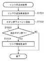
図11は、UIモジュール304の外部公開インタフェースの実行処理を表すフローチャートである。図11のフローに係るプログラムは、外部メモリ11に記憶されており、RAM2に読み出され、CPU1により実行される。まず、UIモジュール304の制御部406がリンク実行部404により入力されたコマンドを取得する(S1101)。次に制御部406が、入力されたコマンドを判定する(S1102)。ここでは、ExecuteCustomLinkコマンドが入力されているとし、S1107に進み、制御部406がリンク実行部409を介して、リンクの実行処理を実行する(S1107)。リンクの実行処理が完了したら、本処理フローを終了する。 FIG. 11 is a flowchart showing execution processing of the external public interface of the
図16は、UIモジュール304により実行されるリンクの追加処理を表すフローチャートである。図16のフローに係るプログラムは、外部メモリ11に記憶されており、RAM2に読み出され、CPU1により実行される。 FIG. 16 is a flowchart showing link addition processing executed by the
まず、制御部406がリンク管理部408を介してリンク情報保存部410に格納された、カスタムリンク情報を読み出す(S1601)。次に制御部406は、リンク管理部408を介してS1601にて取得したカスタムリンク情報内のリンクタイプが、「Application」であるかどうかを判定する(S1602)。図10(b)の例では、リンクタイプが「Web」に設定されているため、リンクタイプが「Application」ではないと判定され(S1602にてNO)、S1604に進む。S1604では、制御部406がリンク実行部409を介して、リンクコマンド1005に記載のコマンドを実行する。図10(b)の例では、リンクタイプが「Web」に設定されているので、リンク実行部409がWebブラウザを起動し、リンクコマンド1005に記載のURLのWebページを表示する。図10(b)のカスタムリンク情報の例では、リンクコマンド1005のURLに対応した図13に示すようなWebページ1300が表示される。 First, the
一方、カスタムリンク情報が図10(c)に示すような状態である場合には、S1602にてリンクタイプが「Application」であると判定され(S1602にてYES)、S1603に進む。S1603では、制御部406がリンク実行部409を介して、リンクコマンド1008が実行可能か否かを判定する。S1603では、例えばリンクコマンドに設定されたアプリケーションへのファイルパスが存在するかどうかによって、実行可能か否かを判定することができる。これにより実行判定手段を実現する。S1603にて、リンクコマンドが実行可能と判定された場合には(S1603にてYES)、S1604に進み、リンク実行部409がリンクコマンドに記載されたファイルパスに従ってアプリケーションを実行する。アプリケーションの実行が完了した後、本処理フローを終了する。一方、S1603にてリンクコマンドは実行不可と判定された場合には(S1603にてNO)、S1605に進み、制御部406がリンクの追加処理を実行する。S1605のリンクの追加処理は、図15に記載のフローチャートと同じ処理が実行され、リンクの追加画面を表示してリンクの再作成を促す。リンクの追加処理が完了した後、本処理フローを終了する。 On the other hand, if the custom link information is in the state as shown in FIG. 10C, it is determined in S1602 that the link type is “Application” (YES in S1602), and the process proceeds to S1603. In step S1603, the
[カスタムリンクの管理処理]
以下では、図7(c)のカスタムリンク管理ボタン712が押下された際の動作について説明する。デバイス管理画面702のカスタムリンク管理ボタン712が押下されると、デバイス管理アプリケーション80のデバイス管理制御部402がリンク実行部404を介して図8に示す要素830の内容を実行する。要素830が実行されると、デバイス管理アプリケーション80が、UIモジュール304(DriverUI.dll)を呼び出し、外部公開インタフェースManageCustomLinkを実行する。[Custom link management process]
Hereinafter, an operation when the custom
図11は、UIモジュール304の外部公開インタフェースの実行処理を表すフローチャートである。図11のフローに係るプログラムは、外部メモリ11に記憶されており、RAM2に読み出され、CPU1により実行される。 FIG. 11 is a flowchart showing execution processing of the external public interface of the
UIモジュール304の外部公開インタフェースManageCustomLinkが実行されると、UIモジュール304の制御部406がリンク実行部404により入力されたコマンドを取得する(S1101)。次に制御部406が、入力されたコマンドを判定する(S1102)。ここでは、ManageCustomLinkコマンドが実行されているため、S1108に進み。制御部406がリンク実行部409を介して、リンク管理処理を実行する(S1108)。その後、S1108にてリンク管理処理が完了したら、処理フローを終了する。 When the external public interface ManageCustomLink of the
なお、S1102にて、入力されたコマンドがUIモジュール304の外部公開インタフェースに該当しないコマンドであった場合には、Defaultの処理に進み、そのまま何もせずに本処理フローを終了する。 If the input command is a command that does not correspond to the external public interface of the
図17は、UIモジュール304により実行されるリンク管理処理を表すフローチャートである。図17のフローに係るプログラムは、外部メモリ11に記憶されており、RAM2に読み出され、CPU1により実行される。 FIG. 17 is a flowchart showing a link management process executed by the
リンク管理処理が実行されると、まず制御部406がUI表示部407を介して、図14(a)に示すようなリンク管理画面1400を表示する(S1701)。リンク管理画面1400は、現在のリンク設定状態1401、削除ボタン1402、変更ボタン1403、キャンセルボタン1404からなる。リンク管理画面1400上で何らかのボタンが押下されると、S1702に進む。S1702では、UI表示部407がリンク管理画面1400上でボタンが押下されたイベントを受信する。次に、制御部406が、S1702にて受信したイベントがリンク管理画面1400上でリンクの削除ボタン1402が押下されたことによるイベントであったか否かを判定する。S1703にてリンクの削除ボタンが押下されたと判定された場合は(S1703にてYES)、S1704に進む。そして、制御部406がリンク管理部408を介してリンク情報保存部410に保持されているリンクタイプ1004およびリンクコマンド1005を削除する(S1704)。結果、カスタムリンク情報は図10の(a)のような初期状態に戻る。これにより、リンク削除を実現する。その後、本処理フローを終了する。 When the link management process is executed, the
一方、S1703にて、制御部406がリンクの削除ボタンが押下されていないと判定した場合には(S1703にてNO)、S1705に進む。S1705では、制御部406が、S1702にて受信したイベントがリンク管理画面1400上で変更ボタン1403が押下されたことによるイベントであったか否かを判定する(S1705)。S1705にてリンクの変更ボタンが押下されたと判定された場合は(S1705にてYES)、制御部406がUI表示部407を介してリンク変更画面1405を表示する(S1706)。 On the other hand, if the
リンク変更画面1405は、ラジオボタン1406、ラジオボタン1407、テキストボックス1408、テキストボックス1409、参照ボタン1410、保存ボタン1411、キャンセルボタン1412からなる。リンク変更画面1405において、保存ボタン1411以外の動作は図12のリンク追加画面1200と同じであるので、ここでは詳細な説明を割愛する。保存ボタン1411は、変更後のカスタムリンク情報の設定が完了した後に押下すると入力されたカスタムリンク情報が外部メモリ11に保存され、リンク変更画面1405を閉じる。 The
リンク変更画面1405において、保存ボタン1411または、キャンセルボタン1412が押下されて画面が閉じられると、S1707に進む。S1707では、UI表示部407がリンク変更画面1405上でボタンが押下されたイベントを受信する。次に、制御部406が、S1707にて受信したイベントがリンク変更画面1405で保存ボタン1411が押下されたことによるイベントであったか否かを判定する(S1708)。S1708において、リンク変更画面1405にて保存ボタン1411が押下されたと判定された場合は(S1708にてYES)、S1709に進む。S1709では、制御部406がリンク管理部408を介して、リンク変更画面1405で指定されたカスタムリンク情報をリンク情報保存部410に保存する。その後、本処理フローを終了する。 When the
S1708にて、リンク変更画面1405にて保存ボタン1411が押下されていないと判定された場合には(S1708にてNO)、そのまま本処理フローを終了する。また、S1705にて、リンクの変更ボタンが押下されていないと判定された場合も(S1705にてNO)、何もせずに本処理フローを終了する。 If it is determined in S1708 that the
以上の処理により、デバイスメタデータパッケージの内容を変更することなくユーザが任意のリンクを追加できる。それにより、ユーザ環境毎にデバイスメタデータパッケージを作成する必要がないため、カスタマイズによるメーカーの負荷が軽減される。さらに、プリンタドライバを介してカスタムリンク情報を追加するので、追加のアプリケーションを必要とせず、安全なカスタマイズ手段を提供できる。 Through the above processing, the user can add an arbitrary link without changing the contents of the device metadata package. Thereby, since it is not necessary to create a device metadata package for each user environment, the burden on the manufacturer due to customization is reduced. Furthermore, since the custom link information is added via the printer driver, a safe customization means can be provided without requiring an additional application.
<第2の実施形態>
以下、本発明に係る第2の実施形態を、図面を参照して説明する。本実施形態においては、図6のS605にて図19に記載のデバイスメタデータパッケージ1900が、署名された状態でPC300の外部メモリ11内における所定の位置に保存された場合について説明する。<Second Embodiment>
Hereinafter, a second embodiment according to the present invention will be described with reference to the drawings. In the present embodiment, a case will be described in which the
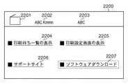
ここでは図7(a)のプリンタ701が選択され、図22に示すデバイス管理画面2200が起動された場合の例について説明する。デバイス管理画面2200は図7(a)に示すDevice and Printersフォルダ700内のデバイスが選択されることにより起動・表示される。 Here, an example in which the
[ソフトウェア構成]
図18は、本実施形態におけるデバイス管理アプリケーション80とプリンタドライバ50のソフトウェア構成図を示す。デバイス管理アプリケーション80は、表示部401、デバイス管理制御部402、デバイスメタデータパッケージ読取り部403、リンク実行部404からなる。デバイスメタデータパッケージ格納部405には、図6のフローのS604で外部メモリ11内の所定の位置に保存されたデバイスメタデータパッケージ1900が保持されている。Software configuration
FIG. 18 is a software configuration diagram of the
プリンタドライバ50は、制御部406、UI表示部407、リンク管理部408、リンク実行部409、情報収集部1801、情報保存部1802、URL生成部1803からなる。情報保存部1802は、外部メモリ11など不揮発性の記憶領域に情報が保持される。図21(a)は情報保存部1802が保持するWebサイトリンク関連情報の一例である。Webサイトリンク関連情報は、WebサイトのURLを生成するのに必要な情報を示し、OS情報2101、モデル情報2102からなる。さらにOS情報2101は、PC300のOSの情報を示し、モデル情報2102は、プリンタ150のモデル情報を示す。初期状態では、OS情報2101、モデル情報2102はそれぞれ空の状態となっている。 The
[デバイス管理画面起動処理フロー]
図9は、図7(a)のDevices and Printersフォルダ700からプリンタ701が選択されることに応じて、デバイス管理アプリケーション80が図22のデバイス管理画面2200を起動する処理を表すフローチャートである。図9のフローに係るプログラムは、外部メモリ11に記憶されており、RAM2に読み出され、CPU1により実行される。[Device management screen startup processing flow]
FIG. 9 is a flowchart showing processing in which the
Device and Printersフォルダ700内のプリンタ701が選択されると、デバイス管理アプリケーション80がデバイス管理画面の起動の処理を開始する。まず、デバイス管理制御部402がDevice and Printersフォルダ500にて選択されたデバイス名を取得する(S901)。本実施形態においては、プリンタ701が選択されているので、「ABC Kmmn」というデバイス名が取得される。 When the
次に、S901で取得したデバイス名に応じたデバイスメタデータパッケージ1900をデバイスメタデータパッケージ読取り部403が読み込む(S902)。デバイスメタデータパッケージ読取り部403は、S902で読み込んだファイルに付加された電子署名でデバイスメタデータパッケージを検証する(S903)。次に、デバイスメタデータパッケージ読取り部403が、S903でデバイスメタデータパッケージが正当であるか否かを判定する(S904)。S904にて、デバイスメタデータパッケージが正当であると判定された場合は(S904にてYES)、デバイスメタデータパッケージ読取り部403が図19に示すデバイスメタデータパッケージ1900の記述内容を解析する(S905)。 Next, the device metadata
デバイスメタデータパッケージ読取り部403が解析したデータの内容に従い、デバイス管理制御部402が表示部401を介してデバイス管理画面2200を表示する(S906)。デバイス管理画面2200を表示した後、デバイス管理アプリケーション80は本処理フローを終了する。 In accordance with the content of the data analyzed by the device metadata
一方、S904にて、デバイスメタデータパッケージが正当でないと判定された場合には(S904にてNO)、何もせずに本処理フローを終了する。この場合は、図7のDevice and Printersフォルダ700の画面は変更されない。 On the other hand, if it is determined in S904 that the device metadata package is not valid (NO in S904), this processing flow ends without doing anything. In this case, the screen of the Device and
デバイスメタデータパッケージ1900の要素801から要素809については、図8のデバイスメタデータパッケージ800と同じ記述であるため、図22の要素2201から要素2205について、ここでは説明を割愛する。 Since the
[表示される機能について]
デバイスメタデータパッケージ1900に記載された要素1901および要素1902とデバイス管理画面2200に表示される各ボタンとの関係について以下で説明する。[Displayed functions]
The relationship between the
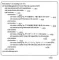
要素1901について説明する。要素1902には、サポートサイトリンクボタン2206上に表示される「サポートサイト」という文字列がセットされている。サポートサイトリンクボタン2206は、Webサーバ201で運用されているABC社の製品に関わるサポートサイトへ接続する機能を有する。要素1903には、UIモジュール304のサポートサイトへのリンク機能を実行する以下のコマンドが記載されている。
rundll32 DriverUI.dll,SupportSiteLinkThe
rundll32 DriverUI. dll, SupportSiteLink
DriverUI.dllは、UIモジュール304のモジュール名で、SupportSiteLinkは、UIモジュール304の外部公開インタフェースである。 DriverUI. dll is a module name of the
次に、要素1904を説明する。要素1905には、ソフトウェアダウンロードボタン2207上に表示される「ソフトウェアダウンロード」という文字列がセットされている。ソフトウェアダウンロードボタン2207は、Webサーバ201で運用されているABC社の製品に関するプリンタドライバなどのソフトウェアを提供するサイトへ接続する機能を有する。要素1906には、UIモジュール304のソフトウェアダウンロードサイトへのリンク機能を実行する以下のコマンドが記載されている。
rundll32 DriverUI.dll,SoftwareDLSiteLinkNext, the
rundll32 DriverUI. dll, SoftwareDLSiteLink
DriverUI.dllは、UIモジュール304のモジュール名で、SoftwareDLSiteLinkは、UIモジュール304の外部公開インタフェースである。 DriverUI. “dll” is a module name of the
[Webサイトリンク機能の説明]
以下では、デバイス管理画面2200のサポートサイトリンクボタン2206およびソフトウェアダウンロードボタン2207が押下された際の動作について説明する。デバイス管理画面2200のサポートサイトリンクボタン2206が押下されると、デバイス管理アプリケーション80のデバイス管理制御部402がリンク実行部404を介して図19の要素1903の内容を実行する。要素1903が実行されると、デバイス管理アプリケーション80が、UIモジュール304(DriverUI.dll)を呼び出し、外部公開インタフェースSupportSiteLinkを実行する。[Description of Web site link function]
Hereinafter, an operation when the support
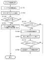
図20は、UIモジュール304の外部公開インタフェースの実行処理を表すフローチャートである。図20のフローに係るプログラムは、外部メモリ11に記憶されており、RAM2に読み出され、CPU1により実行される。 FIG. 20 is a flowchart showing the execution process of the external public interface of the
UIモジュール304の外部公開インタフェースSupportSiteLinkが実行されると、UIモジュール304の制御部406がリンク管理部408を介して、情報保存部1802にWebリンク関連情報が格納されているか否かを判定する(S2001)。図21(a)に示すようにOS情報2101、モデル情報2102が空の状態であると、S2001にて、Webサイトリンク関連情報が格納されていないと判定され(S2001にてNO)、S2002に進む。S2002では、情報収集部1801がAPI/DDI303を介してPC300のOS情報とプリンタ150のモデル情報を取得する。 When the external public interface SupportSiteLink of the
次に、情報収集部1801がS2002にて取得したWebサイトリンク関連情報を情報保存部1802に保存する。図21(b)は情報保存部1802にWebサイトリンク関連情報が保存された状態を示す。OS情報2103には、PC300のOSである「OS AAA」が格納され、モデル情報2104には、プリンタ150のモデル名である「Kmmn」が格納されている。 Next, the
次に、UIモジュール304の制御部406がリンク実行部404により入力されたコマンドを取得する(S2004)。そして、制御部406は、S2004で取得したコマンドを判定する(S2005)。ここでは、SupportSiteLinkコマンドが実行されているため、S2006に進む。S2006では、リンク管理部408がURL生成部1803を介して、サポートサイトへ接続するためのURLを生成する。URL生成部1803は、内部で保持する以下に示すようなサポートサイトのURLと、情報保存部1802に保持されたWebサイトリンク関連情報のモデル情報2104の内容を合成してリンク生成を行う。
http://xxx.abc_company.co.jp/support/Next, the
http: // xxx. abc_company. co. jp / support /
モデル情報2104には、プリンタ150のモデル名である「Kmmn」が格納されているので、S2006では、URL生成部1803が以下のようなURLを生成する。
http://xxx.abc_company.co.jp/support/KmmnSince “Kmmn”, which is the model name of the
http: // xxx. abc_company. co. jp / support / Kmmn
結果、URL生成部1803は、ユーザが使用する機器に応じたサポートサイトのURLを生成する。 As a result, the
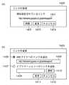
次に、リンク実行部409が、Webブラウザを起動し、S2006で生成されたURLのWebサイトを表示する(S2007)。その後、本処理フローを終了する。S2007では、図23(a)に示すようなABC社が運用するWebサーバ201で公開されたWebページ2301が表示される。Webページ2301にはプリンタモデルKmmnに関するサポート情報が記載されている。 Next, the
次に、デバイス管理画面2200にて、ソフトウェアダウンロードボタン2207が押下された場合の処理について説明する。ソフトウェアダウンロードボタン2207が押下されると、デバイス管理アプリケーション80のデバイス管理制御部402がリンク実行部404を介して図19の要素1906の内容を実行する。要素1906が実行されると、デバイス管理アプリケーション80が、UIモジュール304(DriverUI.dll)を呼び出し、外部公開インタフェースSoftwareDLSiteLinkを実行する。 Next, processing when the
UIモジュール304の外部公開インタフェースSoftwareDLSiteLinkが実行されると、図20に記載の処理が実行される。まず、UIモジュール304の制御部406がリンク管理部408を介して、情報保存部1802にWebリンク関連情報が格納されているか否かを判定する(S2001)。図21(b)に示すようにOS情報2101、モデル情報2102が格納された状態であると、S2001にて、Webサイトリンク関連情報が格納されていると判定され(S2001にてYES)、S2004に進む。 When the external public interface SoftwareDLSiteLink of the
S2004では、UIモジュール304の制御部406がリンク実行部404により入力されたコマンドを取得し、制御部406がS2004で取得したコマンドを判定する(S2005)。ここでは、SoftwareDLSiteLinkコマンドが実行されているため、S2008に進む。S2008では、URL生成部1803が、ソフトウェアダウンロードサイトへ接続するためのURLを生成する。URL生成部1803は、内部で保持する以下に示すようなサポートサイトのURLと、情報保存部1802に保持されたWebサイトリンク関連情報のOS情報2103とモデル情報2104の内容を合成する。
http://xxx.abc_company.co.jp/driver_download/In S2004, the
http: // xxx. abc_company. co. jp / driver_download /
OS情報2103、モデル情報2104には、それぞれ「OS AAA」、「Kmmn」が格納されているので、S2006では、URL生成部1803が以下のようなURLを生成する。
http://xxx.abc_company.co.jp/driver_download/Kmmn/OS_AAASince “OS AAA” and “Kmmn” are stored in the
http: // xxx. abc_company. co. jp / driver_download / Kmmn / OS_AAA
結果、URL生成部1803はユーザが使用する環境に応じたソフトウェアダウンロードサイトのURLを生成する。ここで、OS情報の「OS AAA」に含まれるスペースの文字についてはアンダースコア「_」で埋められる。つまり、「OS_AAA」となる。 As a result, the
次に、リンク実行部409が、Webブラウザを起動し、S2008で生成されたURLのWebサイトを表示する(S2009)。その後、本処理フローを終了する。S2009では、図23(b)に示すようなABC社が運用するWebサーバ201で公開されたWebページ2302が表示される。Webページ2302にはプリンタモデルKmmnの「OS AAA」向けのプリンタドライバのダウンロードサイトが表示される。 Next, the
以上の処理により、プリンタドライバ50でユーザの使用環境の情報を収集することで、デバイスメタデータパッケージの内容を変更することなく適切なWebサイトにユーザを導くことができるため、使い勝手が向上する。 As a result of collecting the information of the user's usage environment by the
<その他の実施形態>
また、本発明は、以下の処理を実行することによっても実現される。即ち、上述した実施形態の機能を実現するソフトウェア(プログラム)を、ネットワーク又は各種記憶媒体を介してシステム或いは装置に供給し、そのシステム或いは装置のコンピュータ(またはCPUやMPU等)がプログラムを読み出して実行する処理である。<Other embodiments>
The present invention can also be realized by executing the following processing. That is, software (program) that realizes the functions of the above-described embodiments is supplied to a system or apparatus via a network or various storage media, and a computer (or CPU, MPU, or the like) of the system or apparatus reads the program. It is a process to be executed.
Claims (12)
Translated fromJapanese前記周辺機器を管理する機能を示す表示を制御するための情報および機能それぞれを提供するリンク先を示すリンク情報が定義され、改竄の有無を確認するために電子署名された情報である周辺装置管理機能制御情報を記憶する記憶手段と、
前記周辺機器管理部からのリクエストを受信するリクエスト受信手段と、
前記リクエスト受信手段にて受信したリクエストに応じて実行される、前記周辺装置管理機能制御情報に含まれるリンク情報とは別のリンク情報を管理するリンク管理手段と、
前記周辺装置管理機能制御情報に含まれるリンク情報もしくは前記リンク管理手段により管理された前記別のリンク情報を用い、前記リクエスト受信手段にて受信したリクエストに基づいてリンク先を決定し、決定されたリンク先へのリンク処理を実行する実行手段と
を有することを特徴とする情報処理装置。An information processing apparatus connected to a peripheral device and having a peripheral device management unit for managing the peripheral device,
Peripheral device management which is information digitally signed to confirm whether or not tampering is defined, and information for controlling display indicating the function for managing the peripheral device and link information indicating a link destination providing each function Storage means for storing function control information;
Request receiving means for receiving a request from the peripheral device management unit;
Link management means for managing link information different from the link information included in the peripheral device management function control information, which is executed in response to the request received by the request receiving means;
Using the link information included in the peripheral device management function control information or the other link information managed by the link management means, the link destination is determined based on the request received by the request receiving means, An information processing apparatus comprising execution means for executing a link process to a link destination.
前記別のリンク情報は、前記リンク追加手段により追加されたリンク情報であることを特徴とする請求項1に記載の情報処理装置。The link management means further includes a link addition means for adding link information to an arbitrary function,
The information processing apparatus according to claim 1, wherein the another link information is link information added by the link addition unit.
ユーザの権限情報を取得する権限取得手段と、
前記権限取得手段により取得された権限情報を判定する判定手段と
を更に有し、
取得された前記権限情報に対して、前記判定手段により前記リンク情報の追加が可能か否かを判定し、前記リンク情報の追加が不可の場合には前記リンク追加手段にて前記リンク情報を追加しないことを特徴とする請求項2乃至5のいずれか一項に記載の情報処理装置。The link management means includes
Authority acquisition means for acquiring user authority information;
Determination means for determining authority information acquired by the authority acquisition means;
It is determined whether the link information can be added by the determination unit with respect to the acquired authority information. If the link information cannot be added, the link addition unit adds the link information. The information processing apparatus according to claim 2, wherein the information processing apparatus is not.
前記実行判定手段により当該リンク情報に対応するリンク先へのリンク処理が実行不可と判定された場合には、前記UI表示手段により当該リンク情報に対応するリンク先を指定するための画面を表示することを特徴とする請求項3乃至6のいずれか一項に記載の情報処理装置。The link management means further comprises execution determination means for determining whether or not the link processing of the link information added by the link addition means can be executed,
When it is determined by the execution determination means that the link processing corresponding to the link information corresponding to the link information cannot be executed, the UI display means displays a screen for designating the link destination corresponding to the link information. The information processing apparatus according to claim 3, wherein the information processing apparatus is an information processing apparatus.
リンク情報が示すリンク先の決定に必要な情報を収集する情報収集手段と、
前記情報収集手段により収集した情報を用いて前記リンク情報を生成するリンク生成手段と
を更に有することを特徴とする請求項1乃至7のいずれか一項に記載の情報処理装置。The link management means includes
Information collection means for collecting information necessary for determining the link destination indicated by the link information;
The information processing apparatus according to claim 1, further comprising: a link generation unit that generates the link information using information collected by the information collection unit.
前記情報処理装置は、前記周辺機器を管理する機能を示す表示を制御するための情報および機能それぞれを提供するリンク先を示すリンク情報が定義され、改竄の有無を確認するために電子署名された情報である周辺装置管理機能制御情報を有し、
前記情報処理装置のリクエスト受信手段が、前記周辺機器管理部からのリクエストを受信するリクエスト受信工程と、
前記情報処理装置のリンク管理手段が、前記リクエスト受信工程において受信したリクエストに応じて実行される、前記周辺装置管理機能制御情報に含まれるリンク情報とは別のリンク情報を管理するリンク管理工程と、
前記情報処理装置の実行手段が、前記周辺装置管理機能制御情報に含まれるリンク情報もしくは前記リンク管理工程において管理された前記別のリンク情報を用い、前記リクエスト受信工程において受信したリクエストに基づいてリンク先を決定し、決定されたリンク先へのリンク処理を実行する実行工程と
を有することを特徴とする制御方法。A method for controlling an information processing apparatus connected to a peripheral device and having a peripheral device management unit for managing the peripheral device,
In the information processing apparatus, information for controlling a display indicating a function for managing the peripheral device and link information indicating a link destination for providing each function are defined, and an electronic signature is used to confirm whether or not tampering has occurred. Peripheral device management function control information that is information,
The request receiving unit of the information processing apparatus receives a request from the peripheral device management unit,
A link management step for managing link information different from the link information included in the peripheral device management function control information, wherein the link management means of the information processing device is executed in response to the request received in the request reception step; ,
The execution unit of the information processing device uses the link information included in the peripheral device management function control information or the other link information managed in the link management step, and links based on the request received in the request reception step A control method comprising: an execution step of determining a destination and executing a link process to the determined link destination.
周辺機器を管理する機能を示す表示を制御するための情報および機能それぞれを提供するリンク先を示すリンク情報が定義され、改竄の有無を確認するために電子署名された情報である周辺装置管理機能制御情報を記憶する記憶手段、
周辺機器管理部からのリクエストを受信するリクエスト受信手段、
前記リクエスト受信手段にて受信したリクエストに応じて実行される、前記周辺装置管理機能制御情報に含まれるリンク情報とは別のリンク情報を管理するリンク管理手段、
前記周辺装置管理機能制御情報に含まれるリンク情報もしくは前記リンク管理手段により管理された前記別のリンク情報を用い、前記リクエスト受信手段にて受信したリクエストに基づいてリンク先を決定し、決定されたリンク先へのリンク処理を実行する実行手段
として機能させるためのプログラム。Computer
Peripheral device management function, which is information that is digitally signed to check whether or not tampering has been defined, and information for controlling display that indicates functions for managing peripheral devices and link information that indicates link destinations that provide each function Storage means for storing control information;
Request receiving means for receiving a request from the peripheral device management unit,
Link management means for managing link information different from the link information included in the peripheral device management function control information, which is executed in response to the request received by the request receiving means;
Using the link information included in the peripheral device management function control information or the other link information managed by the link management means, the link destination is determined based on the request received by the request receiving means, A program for functioning as an execution means for executing a link process to a link destination.
Priority Applications (5)
| Application Number | Priority Date | Filing Date | Title |
|---|---|---|---|
| JP2010097420AJP5511483B2 (en) | 2010-04-20 | 2010-04-20 | Information processing apparatus, control method, and program |
| EP11160347.8AEP2381355B1 (en) | 2010-04-20 | 2011-03-30 | Information processing apparatus, control method, and program |
| KR1020110033634AKR101421780B1 (en) | 2010-04-20 | 2011-04-12 | Information processing apparatus, control method, and computer-readable medium |
| US13/085,847US8587797B2 (en) | 2010-04-20 | 2011-04-13 | Information processing apparatus, control method, and computer-readable medium to determine link information for management of a peripheral device |
| CN201110097084.1ACN102236614B (en) | 2010-04-20 | 2011-04-15 | Signal conditioning package and control method |
Applications Claiming Priority (1)
| Application Number | Priority Date | Filing Date | Title |
|---|---|---|---|
| JP2010097420AJP5511483B2 (en) | 2010-04-20 | 2010-04-20 | Information processing apparatus, control method, and program |
Publications (3)
| Publication Number | Publication Date |
|---|---|
| JP2011227739A JP2011227739A (en) | 2011-11-10 |
| JP2011227739A5 JP2011227739A5 (en) | 2013-06-06 |
| JP5511483B2true JP5511483B2 (en) | 2014-06-04 |
Family
ID=44170345
Family Applications (1)
| Application Number | Title | Priority Date | Filing Date |
|---|---|---|---|
| JP2010097420AActiveJP5511483B2 (en) | 2010-04-20 | 2010-04-20 | Information processing apparatus, control method, and program |
Country Status (5)
| Country | Link |
|---|---|
| US (1) | US8587797B2 (en) |
| EP (1) | EP2381355B1 (en) |
| JP (1) | JP5511483B2 (en) |
| KR (1) | KR101421780B1 (en) |
| CN (1) | CN102236614B (en) |
Families Citing this family (5)
| Publication number | Priority date | Publication date | Assignee | Title |
|---|---|---|---|---|
| US9317272B2 (en)* | 2013-03-15 | 2016-04-19 | Yahoo! Inc. | Computerized system and method for creating a resource URL for rendering the resource in a resource specific application |
| JP2016051395A (en) | 2014-09-01 | 2016-04-11 | キヤノン株式会社 | Image forming apparatus and resource management method |
| US9983862B2 (en)* | 2015-02-16 | 2018-05-29 | Dell Products L.P. | Systems and methods for download and installation of drivers for unmanaged information handling resources |
| JP7218142B2 (en)* | 2018-10-16 | 2023-02-06 | キヤノン株式会社 | Information processing device, control method and program for information processing device |
| JP7035124B2 (en)* | 2020-07-14 | 2022-03-14 | キヤノン株式会社 | Information processing equipment, control methods, and programs |
Family Cites Families (17)
| Publication number | Priority date | Publication date | Assignee | Title |
|---|---|---|---|---|
| US5185628A (en)* | 1991-11-18 | 1993-02-09 | Easatman Kodak Company | Reproduction apparatus with improved operator interactive display for use in job set-up |
| US6184998B1 (en)* | 1997-09-15 | 2001-02-06 | Canon Kabushiki Kaisha | Adding printing to the windows registry |
| TW405083B (en) | 1997-11-06 | 2000-09-11 | Ibm | Asynchronous printing of WEB documents |
| US6614550B1 (en)* | 1998-10-02 | 2003-09-02 | Canon Kabushiki Kaisha | Information processing apparatus, information processing method, and program storage medium |
| US20030030664A1 (en)* | 2001-08-13 | 2003-02-13 | Parry Travis J. | Customizable control panel software |
| JP2004046537A (en)* | 2002-07-11 | 2004-02-12 | Canon Inc | Image processing apparatus and processing method thereof |
| JP2004195972A (en)* | 2002-12-06 | 2004-07-15 | Hitachi Printing Solutions Ltd | Printing device, program, and storage medium |
| JP2005010939A (en)* | 2003-06-17 | 2005-01-13 | Mitsubishi Electric Corp | Digital device system, digital device management apparatus, and digital device |
| US20050085589A1 (en)* | 2003-10-20 | 2005-04-21 | General Electric Company | Modified weatherable polyester molding composition |
| KR20050065037A (en)* | 2003-12-24 | 2005-06-29 | 삼성전자주식회사 | Data processing method of print control device having printer driver |
| KR20060033204A (en)* | 2004-10-14 | 2006-04-19 | 삼성전자주식회사 | How to Display Print Options Provided by the Printer Driver |
| JP2006133520A (en) | 2004-11-05 | 2006-05-25 | Fuji Xerox Co Ltd | Image forming apparatus, method for customizing display screen in image forming apparatus, and display screen customizing program |
| GB0427696D0 (en)* | 2004-12-17 | 2005-01-19 | Ncr Int Inc | Method of authenticating an executable application |
| JP2006189920A (en)* | 2004-12-28 | 2006-07-20 | Canon Marketing Japan Inc | User interface apparatus, display method for user interface, and program |
| JP2007193713A (en)* | 2006-01-21 | 2007-08-02 | Jae-Jun Lee | System for providing information on and ordering printer consumable |
| JP4871615B2 (en)* | 2006-03-07 | 2012-02-08 | 株式会社日立ハイテクノロジーズ | Automatic analyzer |
| JP5321120B2 (en)* | 2008-04-08 | 2013-10-23 | 株式会社リコー | Information processing apparatus, information processing method, and recording medium |
- 2010
- 2010-04-20JPJP2010097420Apatent/JP5511483B2/enactiveActive
- 2011
- 2011-03-30EPEP11160347.8Apatent/EP2381355B1/ennot_activeNot-in-force
- 2011-04-12KRKR1020110033634Apatent/KR101421780B1/ennot_activeExpired - Fee Related
- 2011-04-13USUS13/085,847patent/US8587797B2/enactiveActive
- 2011-04-15CNCN201110097084.1Apatent/CN102236614B/enactiveActive
Also Published As
| Publication number | Publication date |
|---|---|
| CN102236614B (en) | 2015-07-29 |
| US8587797B2 (en) | 2013-11-19 |
| KR20110116985A (en) | 2011-10-26 |
| KR101421780B1 (en) | 2014-07-30 |
| JP2011227739A (en) | 2011-11-10 |
| EP2381355B1 (en) | 2018-07-11 |
| US20110255122A1 (en) | 2011-10-20 |
| CN102236614A (en) | 2011-11-09 |
| EP2381355A2 (en) | 2011-10-26 |
| EP2381355A3 (en) | 2017-04-26 |
Similar Documents
| Publication | Publication Date | Title |
|---|---|---|
| JP7328405B2 (en) | Information processing apparatus, information processing apparatus control method, and print setting application | |
| JP4861883B2 (en) | Image forming apparatus and application execution method | |
| JP4565505B2 (en) | PRINT CONTROL DEVICE, PRINT CONTROL METHOD, PROGRAM, AND RECORDING MEDIUM | |
| KR101511835B1 (en) | Print system, client, control method, and computer readable recording medium | |
| US9025172B2 (en) | Printing setting apparatus, computer readable recording medium, and image forming system for generating printing setting information described in one data format included in plural types of data formats and submitting a printing job to an image forming apparatus capable of executing a printing job based on printing setting information described in the plural types of data formats | |
| JP2010231406A (en) | Information distribution apparatus, installation program distribution method, and computer program | |
| US10455101B2 (en) | Server, image processing unit, and non-transitory recording medium for displaying error screen | |
| JP5804749B2 (en) | Data processing apparatus, data processing method and program | |
| US8176210B2 (en) | Unified host application and associated methodology of integrating local service of a multi-function printer | |
| US10129421B2 (en) | System and method for remote device interface customization | |
| JP5511483B2 (en) | Information processing apparatus, control method, and program | |
| US9606761B2 (en) | Information processing apparatus for controlling an output process and method for the same | |
| JP5564323B2 (en) | Display screen generation program, display screen generation device, and display screen generation method | |
| JP5709429B2 (en) | Image processing apparatus, control method therefor, and program | |
| JP5893295B2 (en) | Information processing apparatus, display method, and program | |
| JP5697393B2 (en) | Information processing apparatus, peripheral device control method, and program | |
| JP2015232754A (en) | Information processing apparatus, data processing apparatus, printer, method of processing driver of information processing apparatus, method of processing driver of data processing apparatus, method of processing driver of printer, and program | |
| JP5043993B2 (en) | Information processing apparatus, information processing apparatus control method, and program | |
| JP7257118B2 (en) | MULTI-FUNCTIONAL PERIPHERAL DEVICE, MULTI-FUNCTIONAL PERIPHERAL DEVICE SYSTEM AND USER INTERFACE CUSTOMIZATION METHOD FOR MULTIFUNCTIONAL PERIPHERAL DEVICE | |
| KR20120018564A (en) | E-book device and method for printing contents thereof | |
| JP2011186767A (en) | Image forming apparatus, image processing apparatus, image processing system, image processing method, program, and recording medium | |
| JP2008183725A (en) | Image forming apparatus capable of connecting external memory | |
| JP2007306396A (en) | Network facsimile machine and image format conversion system | |
| JP2010238141A (en) | Information processing apparatus, image forming system, and screen data management program | |
| JP2012164346A (en) | Information processor, control method for information processor, and program |
Legal Events
| Date | Code | Title | Description |
|---|---|---|---|
| A521 | Request for written amendment filed | Free format text:JAPANESE INTERMEDIATE CODE: A523 Effective date:20130422 | |
| A621 | Written request for application examination | Free format text:JAPANESE INTERMEDIATE CODE: A621 Effective date:20130422 | |
| A977 | Report on retrieval | Free format text:JAPANESE INTERMEDIATE CODE: A971007 Effective date:20140217 | |
| TRDD | Decision of grant or rejection written | ||
| A01 | Written decision to grant a patent or to grant a registration (utility model) | Free format text:JAPANESE INTERMEDIATE CODE: A01 Effective date:20140224 | |
| A61 | First payment of annual fees (during grant procedure) | Free format text:JAPANESE INTERMEDIATE CODE: A61 Effective date:20140325 | |
| R151 | Written notification of patent or utility model registration | Ref document number:5511483 Country of ref document:JP Free format text:JAPANESE INTERMEDIATE CODE: R151 |