JP5511260B2 - Capacitive electromechanical transducer and sensitivity adjustment method thereof - Google Patents
Capacitive electromechanical transducer and sensitivity adjustment method thereofDownload PDFInfo
- Publication number
- JP5511260B2 JP5511260B2JP2009189613AJP2009189613AJP5511260B2JP 5511260 B2JP5511260 B2JP 5511260B2JP 2009189613 AJP2009189613 AJP 2009189613AJP 2009189613 AJP2009189613 AJP 2009189613AJP 5511260 B2JP5511260 B2JP 5511260B2
- Authority
- JP
- Japan
- Prior art keywords
- cells
- sensitivity
- electrode
- cell
- electromechanical transducer
- Prior art date
- Legal status (The legal status is an assumption and is not a legal conclusion. Google has not performed a legal analysis and makes no representation as to the accuracy of the status listed.)
- Expired - Fee Related
Links
Images


Classifications
- B—PERFORMING OPERATIONS; TRANSPORTING
- B06—GENERATING OR TRANSMITTING MECHANICAL VIBRATIONS IN GENERAL
- B06B—METHODS OR APPARATUS FOR GENERATING OR TRANSMITTING MECHANICAL VIBRATIONS OF INFRASONIC, SONIC, OR ULTRASONIC FREQUENCY, e.g. FOR PERFORMING MECHANICAL WORK IN GENERAL
- B06B1/00—Methods or apparatus for generating mechanical vibrations of infrasonic, sonic, or ultrasonic frequency
- B06B1/02—Methods or apparatus for generating mechanical vibrations of infrasonic, sonic, or ultrasonic frequency making use of electrical energy
- B06B1/0292—Electrostatic transducers, e.g. electret-type
- Y—GENERAL TAGGING OF NEW TECHNOLOGICAL DEVELOPMENTS; GENERAL TAGGING OF CROSS-SECTIONAL TECHNOLOGIES SPANNING OVER SEVERAL SECTIONS OF THE IPC; TECHNICAL SUBJECTS COVERED BY FORMER USPC CROSS-REFERENCE ART COLLECTIONS [XRACs] AND DIGESTS
- Y10—TECHNICAL SUBJECTS COVERED BY FORMER USPC
- Y10T—TECHNICAL SUBJECTS COVERED BY FORMER US CLASSIFICATION
- Y10T29/00—Metal working
- Y10T29/49—Method of mechanical manufacture
- Y10T29/49002—Electrical device making
- Y10T29/49009—Dynamoelectric machine
Landscapes
- Engineering & Computer Science (AREA)
- Mechanical Engineering (AREA)
- Ultra Sonic Daignosis Equipment (AREA)
- Transducers For Ultrasonic Waves (AREA)
- Investigating Or Analyzing Materials By The Use Of Ultrasonic Waves (AREA)
- Micromachines (AREA)
Description
Translated fromJapanese本発明は、静電容量型超音波変換装置などの容量型電気機械変換装置、及びその感度調整方法に関する。The present invention relates to a capacitive electromechanical transducer such as a capacitive ultrasonic transducer and a sensitivity adjustment method thereof.
近年、マイクロマシニング工程を用いて作製される容量型電気機械変換装置が盛んに研究されている。通常の容量型電気機械変換装置は、下部電極と所定の間隔を保って支持された振動膜と該振動膜の表面に配設される上部電極とを有するセルを含む。これは、例えば、容量型超音波変換装置(CMUT:Capacitive-Micromachined-Ultrasonic-Transducer)などとして用いられる。In recent years, a capacitive electromechanical transducer manufactured using a micromachining process has been actively studied. A typical capacitive electromechanical transducer includes a cell having a lower electrode, a vibrating membrane supported at a predetermined interval, and an upper electrode disposed on the surface of the vibrating membrane. This is used, for example, as a capacitive ultrasonic transducer (CMUT: Capacitive-Micromachined-Ultrasonic-Transducer).
前記変換装置は、軽量の振動膜を用いて、電気信号から超音波への変換と超音波から電気信号への変換のうちの少なくとも一方を行うものであり、液中及び空気中でも優れた広帯域特性を持つものが容易に得られる。この変換装置を利用すると、従来の医療診断より高精度な診断が可能となるため、有望な技術として注目されつつある。この変換装置の動作原理について説明する。超音波を送信する際には、下部電極と上部電極間に、DC電圧に微小なAC電圧を重畳した電圧を印加する。これにより、振動膜が振動し超音波が発生する。超音波を受信する際には、振動膜が超音波により変形するので、変形に伴う下部電極と上部電極間の容量変化により信号を検出する。通常の変換装置は、電気的に接続された複数のセルが並列に電気的に接続されたエレメント(素子)を複数個配置したものが用いられる。こうした構成では、複数のエレメント間で受信感度がばらつくことがあり、これに対して感度補正を行う方法が提案されている(特許文献1参照)。この方法では、各超音波検知素子で変換される出力信号同士の差(感度差)が小さくなる様に制御部で出力信号を電気的に調整する。The conversion device performs at least one of a conversion from an electric signal to an ultrasonic wave and a conversion from an ultrasonic wave to an electric signal by using a lightweight vibrating membrane, and has excellent broadband characteristics in liquid and air. Can easily be obtained. When this conversion device is used, diagnosis with higher accuracy than conventional medical diagnosis is possible, and therefore, it is attracting attention as a promising technology. The operating principle of this conversion device will be described. When transmitting ultrasonic waves, a voltage obtained by superimposing a minute AC voltage on a DC voltage is applied between the lower electrode and the upper electrode. As a result, the vibrating membrane vibrates and ultrasonic waves are generated. When receiving the ultrasonic wave, the vibration film is deformed by the ultrasonic wave, and thus a signal is detected by a change in capacitance between the lower electrode and the upper electrode accompanying the deformation. An ordinary conversion device is used in which a plurality of elements (elements) in which a plurality of electrically connected cells are electrically connected in parallel are arranged. In such a configuration, the reception sensitivity may vary between a plurality of elements, and a method for correcting the sensitivity has been proposed (see Patent Document 1). In this method, the output signal is electrically adjusted by the control unit so that the difference (sensitivity difference) between the output signals converted by the respective ultrasonic detection elements becomes small.
上記セルないしエレメントの感度は、例えば、電極間の間隔(ギャップ)の平方に反比例する。よって、電極間のギャップがばらつきを持つ場合は、前記変換装置の感度のばらつきとなる。容量型電気機械変換装置のギャップの形成方法としては、所望の電極間隔と同等の厚さの犠牲層を設けて、該犠牲層の上部に振動膜を形成し、犠牲層を除去してギャップを形成する方法が、一般に採用されている。The sensitivity of the cell or element is inversely proportional to the square of the gap (gap) between the electrodes, for example. Therefore, when the gap between the electrodes has variations, the sensitivity of the conversion device varies. As a method for forming a gap in a capacitive electromechanical transducer, a sacrificial layer having a thickness equivalent to a desired electrode interval is provided, a vibration film is formed on the sacrificial layer, and the sacrificial layer is removed to form a gap. The forming method is generally adopted.
電気的に接続された複数のセルから成るエレメントを複数個配置した変換装置を用いて超音波等の弾性波の検出を行う場合、複数のエレメント間の感度のばらつきは測定精度の低下を招く。よって、エレメント個々に対して感度を補正する必要である。しかし、特許文献1の様に、後段の回路のゲイン調整により感度補正を行う構成では、回路のダイナミックレンジを広くとる必要がある。更に、一定以上のばらつきがある場合は、補正が不可能となる。When detecting an elastic wave such as an ultrasonic wave by using a conversion device in which a plurality of elements composed of a plurality of electrically connected cells are arranged, variations in sensitivity among the plurality of elements cause a decrease in measurement accuracy. Therefore, it is necessary to correct the sensitivity for each element. However, in the configuration in which the sensitivity correction is performed by adjusting the gain of the subsequent circuit as in Patent Document 1, it is necessary to widen the dynamic range of the circuit. Furthermore, if there is a certain variation, correction is impossible.
上記課題に鑑み、本発明のCMUTなどの容量型電気機械変換装置は、第1の電極と、第1の電極と対向し空隙を隔てて配設された第2の電極とを備えるセルを複数有する。そして、本変換装置では、前記複数のセルの一部のみにおいて、物質の付加と除去のうちの少なくとも一方の加工が施された加工部を有する。In view of the above problems, a capacitive electromechanical transducer such as a CMUT according to the present invention includes aplurality of cellseach including a first electrode and a second electrode disposed opposite to the first electrode and spaced apart fromeach other. Have. Then, in the conversion device,in only a portion ofthe plurality of cells includes a processing unit for at least one of the processing has been performed of the removal and addition of material.
また、上記課題に鑑み、第1の電極と、第1の電極と対向し空隙を隔てて配設された第2の電極とを備えるセルを複数有する容量型電気機械変換装置の本発明の感度調整方法は、前記複数のセルの一部のみに、物質の付加と除去のうちの少なくとも一方を施す加工を行って、前記セルの弾性波(典型的には超音波)に対する出力信号を調整することを特徴とする。Moreover, in view of the said subject, the sensitivity of this invention of the capacity | capacitance type electromechanical transducer which hastwo or more cells provided with the 1st electrode and the 2nd electrode arrange | positioned through the space | gap facing the 1st electrode. adjustment method,only aportion ofthe plurality of cells, by performing at least one of subjecting the processing of removing the additional material, the elastic wave ofthe cell (typically ultrasound) to adjust the output signal to It is characterized by that.
本発明では、複数のセルの一部のみに物質の付加と除去のうちの少なくとも一方を施すので、超音波等の弾性波に対するセルないしエレメントの感度の調整(即ち、超音波等に対する出力信号の調整)、エレメント間の感度のばらつきの低減等を行うことができる。例えば、複数のセルを含む構成や、電気的に接続された複数のセルから成るエレメントを複数個配置した構成の容量型電気機械変換装置で、セルないしエレメントの受信感度を均一にすることができる。また、単に物質の付加、除去を行うという加工であるので、比較的簡単に加工を行うことができる。In the present invention, since at least one of addition and removal of a substance is applied to only a part of a plurality of cells, the sensitivity of the cell or element with respect to elastic waves such as ultrasonic waves is adjusted (that is, the output signal for ultrasonic waves or the like is adjusted). Adjustment), variation in sensitivity between elements can be reduced, and the like. For example, in a capacitive electromechanical transducer having a configuration including a plurality of cells or a configuration in which a plurality of elements composed of a plurality of electrically connected cells are arranged, the reception sensitivity of the cells or elements can be made uniform. . In addition, since the process simply involves adding and removing substances, the process can be performed relatively easily.
以下、本発明の実施形態について説明する。本発明の容量型電気機械変換装置及び感度調整方法において重要なことは、少なくとも1つのセルに対して、物質の付加と除去のうちの少なくとも一方の加工を施すことである。この考え方に基づき、本発明の容量型電気機械変換装置及び感度調整方法の基本的な形態は、上記した様な構成を有する。この基本的な形態を基に、次に述べる様な実施形態が可能である。例えば、変換装置は、複数のセルから構成される素子であるエレメントを複数有する(後述の実施例参照)。また、セルは、基板に配設された第1の電極と、第1の電極と対向し空隙を隔てて配設された第2の電極と、第2の電極を支持する振動膜と、振動膜を支持する支持部とで構成できる(後述の実施例参照)。前記加工部は、セルないしエレメントの弾性波に対する受信感度の調整、複数のエレメント間の弾性波に対する受信感度のばらつきの低減等を行うことができる。本発明において、弾性波とは、音波、超音波、音響波、光音響波と呼ばれるものを示し、被検体内部に近赤外線等の光を照射して被検体内部で発生する弾性波を含む。また、前記加工部は、第2の電極上に振動抑制膜が配置された部分、セルを電気的に接続する接続抵抗を高くした部分、セルの一部に穴を空け空隙を大気圧にした部分、セルの一部を剥離した部分のうちの何れかとなし得る(後述の各実施例参照)。Hereinafter, embodiments of the present invention will be described. What is important in the capacitive electromechanical transducer and sensitivity adjustment method of the present invention is to perform at least one of addition and removal of substances on at least one cell. Based on this concept, the basic form of the capacitive electromechanical transducer and sensitivity adjustment method of the present invention has the configuration as described above. On the basis of this basic form, the following embodiments are possible. For example, the conversion device includes a plurality of elements that are elements composed of a plurality of cells (refer to examples described later). In addition, the cell includes a first electrode disposed on the substrate, a second electrode disposed opposite to the first electrode with a gap, a vibration film supporting the second electrode, and a vibration It can comprise with the support part which supports a film | membrane (refer the below-mentioned Example). The processing unit can adjust reception sensitivity of cells or elements with respect to elastic waves, reduce variations in reception sensitivity with respect to elastic waves between a plurality of elements, and the like. In the present invention, the elastic wave indicates what is called a sound wave, an ultrasonic wave, an acoustic wave, or a photoacoustic wave, and includes an elastic wave generated inside the subject by irradiating the subject with light such as near infrared rays. In addition, the processed portion has a portion where the vibration suppression film is disposed on the second electrode, a portion where the connection resistance for electrically connecting the cells is increased, a hole is formed in a part of the cell, and the air gap is set to atmospheric pressure. It can be any one of a part and a part where a part of the cell is peeled off (see each example described later).
本発明で用いられる第2の電極は、Al、Cr、Ti、Au、Pt、Cu、Ag、W、Mo、Ta、Ni等から選択される導電体や、Si等の半導体、AlSi、AlCu、AlTi、MoW、AlCr、TiN、AlSiCu等から選択される合金のうちの少なくとも一材料により形成することができる。また、第2の電極は、振動膜の上面、裏面、内部のうちの少なくとも一箇所に設けるか、もしくは振動膜を導電体又は半導体で形成する場合は振動膜が第2の電極を兼ねる構造とすることもできる。本発明で用いられる第1の電極も、第2の電極と同様の導電体や半導体等により形成することができる。また、第1の電極と第2の電極材料は異なっていても良い。基板がシリコン等の半導体基板である場合、基板が第1の電極を兼ねることもできる。The second electrode used in the present invention includes a conductor selected from Al, Cr, Ti, Au, Pt, Cu, Ag, W, Mo, Ta, Ni, a semiconductor such as Si, AlSi, AlCu, It can be formed of at least one material selected from alloys selected from AlTi, MoW, AlCr, TiN, AlSiCu, and the like. Further, the second electrode is provided in at least one of the top surface, the back surface, and the inside of the vibration film, or when the vibration film is formed of a conductor or a semiconductor, the vibration film also serves as the second electrode. You can also The first electrode used in the present invention can also be formed using the same conductor, semiconductor, or the like as the second electrode. Further, the first electrode and the second electrode material may be different. When the substrate is a semiconductor substrate such as silicon, the substrate can also serve as the first electrode.
また、容量型電気機械変換装置が、複数のセルから構成されるエレメントを複数有する場合、予め測定した各々のエレメントの超音波等に対する受信感度に応じて、加工するセルの個数を決定し、何らかの加工手段(物質の塗布、レーザ加工などの手段)で当該セルを加工することができる。When the capacitive electromechanical transducer has a plurality of elements composed of a plurality of cells, the number of cells to be processed is determined according to the reception sensitivity of each element measured with respect to ultrasonic waves, etc. The cell can be processed by processing means (material application, laser processing, or the like).
(第1の実施例)
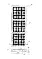
以下、本発明の第1の実施例の加工前(当初の設計に従って作製した段階)の容量型電気機械変換装置を図を用いて説明する。図1(a)及び図1(b)に示す様に、容量型電気機械変換装置100は複数のエレメント101を有し、各エレメント101は複数のセル102が並列に電気的に接続されている。図1(a)では、素子であるエレメント101内に25個のセル102を配置しているが、セルの数はこれに限らない。エレメント内に1以上のセルがあればよい。また、本変換装置は3個のエレメント101を1次元に配置しているが、複数のエレメントを2次元に配列してもよい。本実施例では、セル102は、基板103に配設された下部電極104と、下部電極と対向し所定の空隙105を隔てて配設された上部電極106と、上部電極を支持する振動膜107と、振動膜を支持する支持部108から成る。支持部108は、振動膜107を支持している部分であれば、振動膜107と同じ工程で一体的に形成された振動膜と同一材料からなる部分も含む。下部電極104は変換装置100内で共通であり、エレメント101内のセル102間の上部電極106は、該上部電極と同一部材の配線により電気的に接続されている。ただし、電極の接続態様は、こうしたものに限らない。これらの形態は、仕様に応じて適宜決めればよい。(First embodiment)
Hereinafter, the capacitive electromechanical transducer before processing (stage manufactured according to the original design) of the first embodiment of the present invention will be described with reference to the drawings. As shown in FIGS. 1A and 1B, the capacitive
本実施例において、空隙105の高さは100nmであるが、10nmから500nmの範囲が望ましい。空隙105の一片の長さは10μmから200μmの範囲が好ましい。振動膜107はSiNにより形成されるが、その他の絶縁材料でもよい。空隙105は大気圧に対して減圧状態に保たれており、振動膜107は凹形状となる(後述する図6(b)参照)。本実施例では、振動膜及び電極を角形としたが、円形、多角形などであっても構わない。セルの空隙105の形状も図示例では角形であるが、その他の形状でもよい。In this embodiment, the height of the
セル102は、外部からの弾性波の振動により振動膜107が振動することにより、上下電極106、104間の容量が変化する。各エレメント101の上部電極と下部電極は受信回路(図示しない)に接続されており、受信回路はエレメント内のセルの上下電極間の容量変化を電圧信号に変換する。In the
複数のエレメントの信号を用いて医療診断を行う場合、各エレメントの感度のばらつきは少ない方が望ましい。よって、本実施例では、事前に測定した各エレメントの感度に応じて変換装置のエレメント101内の幾つかのセル102の上面に振動抑制剤を塗布する。こうした加工により、セルの超音波などに対する出力信号が抑制ないし調整され、複数のエレメント101の音波等に対する受信感度を均一にすることができる。When medical diagnosis is performed using signals of a plurality of elements, it is desirable that the variation in sensitivity of each element is small. Therefore, in this embodiment, a vibration suppressing agent is applied to the upper surfaces of some
図2に、こうした感度調整加工により受信感度を調整した容量型電気機械変換装置の上面図及び断面図を示す。本実施例では、一例として、振動抑制剤110はアクリル系の樹脂であり、ディスペンサにより所望のセルの上面に塗布される。振動膜107のばね定数よりも高いばね定数の振動抑制剤110を塗布することで、外部からの音波等の振動による振動膜107の振動を抑制することができる。また、エレメント101内において振動抑制剤110を塗布するセル102の数を変えることで、エレメントの感度を調整できる。例えば、図2(a)の上段、中断、下段の感度調整加工前のエレメントが、下段、上段、中段の順で感度が高いと分かった場合、次の様にする。即ち、図2(a)に示す様に、中段、上段、下段の順で、エレメント101内の振動抑制剤110を塗布するセル102の数を多くすることで、複数のエレメントの音波等の受信感度を均一にできる。調整加工前の上段のエレメントの受信感度を1とし、中段の相対受信感度が0.95、下段の相対受信感度が1.05と分かった場合、調整加工前の感度ばらつきは10%である。ここで、図2(a)に示す様に下段の2個、上段の1個、中段の0個のセル102の上面に、所定の厚さまで振動抑制剤110を塗布する。これにより、上段のエレメントの相対受信感度が0.96、中段のそれが0.95、下段のそれが0.97となり、調整加工前の感度ばらつき10%が1.7%に低減される。ここでは、上段のエレメントに25個のセル102があるので、1つのセル102に振動抑制剤110を塗布する毎に、相対受信感度が0.04低下することになる。下段のエレメントの場合は、1つのセル102に振動抑制剤110を塗布する毎に、相対受信感度が0.042低下することになる。調整前の各エレメント101の相対感度を図3(a)に、調整後の各エレメント101の相対感度を図3(b)に示す。FIG. 2 shows a top view and a cross-sectional view of a capacitive electromechanical transducer in which reception sensitivity is adjusted by such sensitivity adjustment processing. In this embodiment, as an example, the
感度補正の細かさは、各エレメント内にあるセルの個数に依る。よって、エレメント内にあるセルの数を増やすことにより高精度な調整が可能となる。本実施例では、所定の厚さの振動抑制剤を塗布することによりセルの出力信号が完全に抑制されることを前提としている。アクリル系の樹脂の場合、完全に振動を抑制する為には数ミリメートル程度の厚さとすることが好ましい。振動抑制剤の厚さによる抑制率に応じて、加工するセルの数を調整することで同様の効果が得られる。例えば、出力信号の抑制率が50%である場合(これは予めの測定から分かる)は、下段の4個、上段の2個、中段の0個のセル102の上面に振動抑制剤を塗布することにより、同様の効果が得られる。また、振動抑制剤はアクリル系の樹脂に限らず、振動膜の振動を抑制する材料であればよく、異なる材料を用いて多層構造としても良い。この様に、本実施例によれば、加工するセルの数を調整して各エレメントの受信感度を調整することにより、簡便で高精度に受信感度を調整できる。The fineness of sensitivity correction depends on the number of cells in each element. Therefore, high-precision adjustment is possible by increasing the number of cells in the element. In this embodiment, it is assumed that the output signal of the cell is completely suppressed by applying a vibration suppression agent having a predetermined thickness. In the case of an acrylic resin, the thickness is preferably about several millimeters in order to completely suppress vibration. A similar effect can be obtained by adjusting the number of cells to be processed according to the suppression rate depending on the thickness of the vibration suppressor. For example, when the output signal suppression rate is 50% (this is known from the previous measurement), a vibration suppressing agent is applied to the upper surfaces of the lower four cells, the upper two cells, and the middle zero
また、加工するセルのエレメント内での位置を考慮に入れることも可能である。例えば、出力信号の抑制率がエレメントの中心部からのセルの距離に依存することが予め分かっていれば、数と共に位置を考慮して加工セルを決め、複数のエレメントの音波等に対する受信感度を調整することができる。前記容量型電気機械変換装置は、外部に弾性波の発信をも行える様に構成されてもよい。受信、発信は背景技術のところで説明した様に行われる。本実施例では、少なくともエレメントの受信感度が調整できればよいので、上述した様な調整加工を施したが、当然のこととして、加工後にはエレメントの発信効率も変化することになる。It is also possible to take into account the position of the cell to be processed in the element. For example, if it is known in advance that the suppression rate of the output signal depends on the distance of the cell from the center of the element, the processing cell is determined in consideration of the position along with the number, and the reception sensitivity of the multiple elements to the sound wave, etc. is increased. Can be adjusted. The capacitive electromechanical transducer may be configured to be capable of transmitting elastic waves to the outside. Reception and transmission are performed as described in the background art. In this embodiment, since it is sufficient that at least the reception sensitivity of the element can be adjusted, the adjustment processing as described above is performed. However, as a matter of course, the transmission efficiency of the element also changes after the processing.
(第2の実施例)
第2の実施例の容量型電気機械変換装置を説明する。本実施例の変換装置の基本構造は、第1の実施例と同様である。本実施例では、事前に測定した各エレメントの感度に応じて、エレメント内の幾つかのセルの振動膜及び上部電極を除去することで、セルの超音波等に対する出力信号を抑制し、複数のエレメントの受信感度を均一にする。図4に、本実施例の感度調整加工方法により受信感度を調整した変換装置の上面図及び断面図を示す。レーザー加工、エッチング加工等により振動膜107及び上部電極106を除去し、選択的にセル102を加工する。加工されたセルでは、外部からの音波等の振動による容量変化を無くすことができる。よって、エレメント内の振動膜及び上部電極を除去するセルの数を変えることで、エレメントの感度を調整することができる。ここでも、図4(a)に示す様に、下段の2個、上段の1個、中段の0個のセルの振動膜及び上部電極を除去している。これにより、上段のエレメントの相対受信感度が0.96、中段のそれが0.95、下段のそれを0.97となり、調整加工前の感度ばらつきが1.7%に低減される。調整前の各エレメントの相対感度を図3(a)に、調整加工後の各エレメントの相対感度を図3(b)に示す。(Second embodiment)
A capacitive electromechanical transducer of the second embodiment will be described. The basic structure of the conversion device of this embodiment is the same as that of the first embodiment. In this embodiment, according to the sensitivity of each element measured in advance, by removing the vibrating membranes and upper electrodes of several cells in the element, the output signal for the ultrasonic waves of the cell is suppressed, and a plurality of Make the reception sensitivity of the element uniform. FIG. 4 shows a top view and a cross-sectional view of a conversion apparatus whose reception sensitivity is adjusted by the sensitivity adjustment processing method of this embodiment. The vibrating
本実施例では、上部電極と共に振動膜も除去しているが、例えば、上部電極のみの除去でもよい。その他の点は、第1の実施例と同様である。In this embodiment, the vibration film is removed together with the upper electrode, but for example, only the upper electrode may be removed. The other points are the same as in the first embodiment.
(第3の実施例)
第3の実施例の容量型電気機械変換装置を説明する。本実施例の変換装置の基本構造も、第1の実施例と同様である。本実施例では、事前に測定した各エレメントの感度に応じて、エレメント内の幾つかのセルの上部電極の電気的接続を切断する。このことで、セルの超音波等に対する出力信号を抑制し、複数のエレメントの音波等に対する受信感度を均一にする。図5に、本実施例の感度調整加工方法により受信感度を調整した変換装置の上面図及び断面図を示す。レーザー加工、エッチング加工等により上部電極106の電気的接続を選択的に切断する。加工されたセル102では、エレメント101内の他のセルとの電気的接続が切られるため、外部からの音波等の振動による出力信号を抑制することができる。よって、エレメント101内の上部電極106の電気的接続を切断するセル102の数を変えることで、エレメント101の感度を調整できる。ここでも、図5(a)に示す様に、下段の2個、上段の1個、中段の0個のセル102の上部電極106の電気的接続を切断する。これにより、上段のエレメントの相対受信感度が0.96、中段のそれが0.95、下段のそれが0.97となり、調整加工前の感度ばらつきが1.7%に低減される。調整前の各エレメントの相対感度を図3(a)に、調整加工後の各エレメントの相対感度を図3(b)に示す。(Third embodiment)
A capacitive electromechanical transducer according to a third embodiment will be described. The basic structure of the conversion apparatus of this embodiment is the same as that of the first embodiment. In this embodiment, the electrical connection of the upper electrodes of several cells in the element is disconnected according to the sensitivity of each element measured in advance. This suppresses the output signal for the ultrasonic waves of the cell and makes the reception sensitivity of the plurality of elements for the acoustic waves uniform. FIG. 5 shows a top view and a cross-sectional view of a conversion apparatus in which reception sensitivity is adjusted by the sensitivity adjustment processing method of this embodiment. The electrical connection of the
本実施例では、上部電極の電気的接続を切断するセルの出力信号が完全に抑制されることを前提としている。しかし、上部電極間の配線の抵抗を上げることでも同様の効果が得られる場合、その抑制率に応じて、加工するセルの数を調整することで、同様の効果が得られる。例えば、配線の抵抗を上げることによる出力信号の抑制率が50%である場合は、下段の4個、上段の2個、中段の0個の配線の抵抗を上げることで同様の効果が得られる。抵抗を上げる方法としては、配線の幅を細くする、厚さを薄くする等の方法がある。その他の点は、第1の実施例と同様である。In the present embodiment, it is assumed that the output signal of the cell that disconnects the electrical connection of the upper electrode is completely suppressed. However, if the same effect can be obtained by increasing the resistance of the wiring between the upper electrodes, the same effect can be obtained by adjusting the number of cells to be processed according to the suppression rate. For example, when the output signal suppression rate by increasing the wiring resistance is 50%, the same effect can be obtained by increasing the resistance of the lower four wirings, the upper two wirings, and the middle zero wiring. . As a method for increasing the resistance, there are methods such as reducing the width of the wiring and reducing the thickness. The other points are the same as in the first embodiment.
(第4の実施例)
第4の実施例の容量型電気機械変換装置を説明する。本実施例の変換装置の基本構造も、第1の実施例1と同様である。本実施例では、事前に測定した各エレメントの感度に応じて、エレメント内の幾つかのセルの振動膜の一部に穴を開ける。このことで、セルの超音波等に対する出力信号を抑制し、複数のエレメントの音波等の受信感度を均一にする。図6に、本実施例の感度調整加工方法により受信感度を調整した変換装置の上面図及び断面図を示す。加工前のセル102の空隙105は減圧状態となっているため、図6(b)の断面図に示す左側のセル102の様に振動膜107は凹形状をしている(ただし、誇張して示している)。空隙が減圧状態のセルの振動膜107の一部に、レーザー加工、エッチング加工等により貫通穴140を開け、大気圧にする。このことで、図6(b)の断面図に示す右側のセル102の様に振動膜107の凹形状は平面に近づく。これにより、加工前の形状と比べ、外部からの音波等の振動による出力信号を抑制することができる。よって、エレメント内において振動膜の一部に穴140を開けるセルの数を変えることで、エレメントの感度を調整できる。(Fourth embodiment)
A capacitive electromechanical transducer according to a fourth embodiment will be described. The basic structure of the conversion device of this embodiment is the same as that of the first embodiment. In this embodiment, holes are made in some of the vibrating membranes of several cells in the element according to the sensitivity of each element measured in advance. This suppresses an output signal for the ultrasonic waves of the cell and makes the reception sensitivity of the sound waves of the plurality of elements uniform. FIG. 6 shows a top view and a cross-sectional view of a conversion apparatus in which reception sensitivity is adjusted by the sensitivity adjustment processing method of this embodiment. Since the
図6(a)では、セルの出力信号の抑制率が20%である場合の感度調整法を示している。この場合、下段の10個、上段の5個、中段の0個のセルの振動膜の一部に穴140を開ける。これにより、上段のエレメントの相対受信感度が0.96、中段のそれが0.95、下段のそれが0.97となり、調整加工前の感度ばらつきが1.7%に低減される。調整前の各エレメントの相対感度を図3(a)に、調整加工後の各エレメントの相対感度を図3(b)に示す。本実施例では、セルの中央に穴を設けたが、空隙105の大気開放が可能な加工であれば、同様の効果を得られる。その他の点は、第1の実施例と同様である。FIG. 6A shows a sensitivity adjustment method when the cell output signal suppression rate is 20%. In this case, a
上記各実施例において、例えば、受信感度の測定を次の様に行うことができる。変換装置のエレメントと測定装置の超音波送波素子とを所定の関係で対向させて配置し、変換装置のエレメントを受波可能な状態とする。測定装置は該エレメントから出力信号を受ける様にもしておく。測定作業を開始すると、超音波送波素子から所定の超音波を送波する。この超音波は変換装置のエレメントで受波され、測定装置は、該エレメントから出力信号を受け、各エレメントの感度の測定を行う。こうした測定値に基づいて、上述した様にセルの加工の態様を決定し、加工を実行する。可能であれば、測定しつつ、測定値に基づいてセル加工をフィードバック制御して実施することもできる。また、上記実施例は、原理的に可能であれば、組み合わせて用いることもできる。例えば、第1の実施例の振動抑制剤の付加と第3の実施例の上部電極間の配線の抵抗を上げる加工を合わせて行うことなども可能である。In each of the above embodiments, for example, reception sensitivity can be measured as follows. The element of the conversion device and the ultrasonic wave transmitting element of the measurement device are arranged to face each other in a predetermined relationship so that the element of the conversion device can receive waves. The measuring device is also adapted to receive an output signal from the element. When the measurement operation is started, a predetermined ultrasonic wave is transmitted from the ultrasonic wave transmitting element. This ultrasonic wave is received by an element of the conversion device, and the measurement device receives an output signal from the element and measures the sensitivity of each element. Based on these measured values, the processing mode of the cell is determined as described above, and the processing is executed. If possible, the cell processing can also be carried out by feedback control based on the measured value while measuring. Further, the above embodiments can be used in combination if possible in principle. For example, the addition of the vibration suppressor of the first embodiment and the process of increasing the resistance of the wiring between the upper electrodes of the third embodiment can be performed together.
100 容量型電気機械変換装置、101 エレメント(素子)、102 セル、103 基板、104 下部電極(第1の電極)、105 空隙、106 上部電極(第2の電極)、107 振動膜、108 支持部、110 振動抑制剤(加工部)、140 穴(加工部)100 capacitive electromechanical transducer, 101 element (element), 102 cell, 103 substrate, 104 lower electrode (first electrode), 105 gap, 106 upper electrode (second electrode), 107 vibrating membrane, 108 support , 110 Vibration suppressor (processed part), 140 holes (processed part)
Claims (6)
Translated fromJapanese前記複数のセルの一部のみにおいて、物質の付加と除去のうちの少なくとも一方の加工が施された加工部を有することを特徴とする容量型電気機械変換装置。A capacitive electromechanical transducer having aplurality of cellseach including a first electrode and a second electrode disposed opposite to the first electrode and spaced from a gap,
In only a part of theprevious SLplurality of cells, capacitive electromechanical transducer, characterized in that it comprises a processing unit for at least one of the processing has been performed of the removal and addition of material.
前記複数のセルの一部のみに、物質の付加と除去のうちの少なくとも一方を施す加工を行って、前記セルの弾性波に対する出力信号を調整することを特徴とする感度調整方法。A method for adjusting the sensitivity of a capacitive electromechanical transducer having aplurality of cellseach including a first electrode and a second electrode disposed opposite to the first electrode and spaced apart from a gap,
Only part of theprevious SLplurality of cells, the sensitivity adjustment method characterized by performing at least one of subjecting the processing of removing the additional material, to adjust the output signal for the acoustic wave ofthe cell.
Priority Applications (3)
| Application Number | Priority Date | Filing Date | Title |
|---|---|---|---|
| JP2009189613AJP5511260B2 (en) | 2009-08-19 | 2009-08-19 | Capacitive electromechanical transducer and sensitivity adjustment method thereof |
| US13/390,680US8869622B2 (en) | 2009-08-19 | 2010-08-05 | Capacitive electromechanical transducer apparatus and method for adjusting its sensitivity |
| PCT/JP2010/004945WO2011021358A2 (en) | 2009-08-19 | 2010-08-05 | Capacitive electromechanical transducer apparatus and method for adjusting its sensitivity |
Applications Claiming Priority (1)
| Application Number | Priority Date | Filing Date | Title |
|---|---|---|---|
| JP2009189613AJP5511260B2 (en) | 2009-08-19 | 2009-08-19 | Capacitive electromechanical transducer and sensitivity adjustment method thereof |
Publications (2)
| Publication Number | Publication Date |
|---|---|
| JP2011044757A JP2011044757A (en) | 2011-03-03 |
| JP5511260B2true JP5511260B2 (en) | 2014-06-04 |
Family
ID=43607415
Family Applications (1)
| Application Number | Title | Priority Date | Filing Date |
|---|---|---|---|
| JP2009189613AExpired - Fee RelatedJP5511260B2 (en) | 2009-08-19 | 2009-08-19 | Capacitive electromechanical transducer and sensitivity adjustment method thereof |
Country Status (3)
| Country | Link |
|---|---|
| US (1) | US8869622B2 (en) |
| JP (1) | JP5511260B2 (en) |
| WO (1) | WO2011021358A2 (en) |
Families Citing this family (18)
| Publication number | Priority date | Publication date | Assignee | Title |
|---|---|---|---|---|
| JP2013226389A (en)* | 2012-03-31 | 2013-11-07 | Canon Inc | Probe and manufacturing method thereof, and object information acquisition apparatus using the same |
| JP2013226390A (en)* | 2012-03-31 | 2013-11-07 | Canon Inc | Probe and object information acquisition apparatus using the same |
| JP2013226391A (en)* | 2012-03-31 | 2013-11-07 | Canon Inc | Probe and object information acquisition apparatus using the same |
| JP5927294B2 (en)* | 2012-06-11 | 2016-06-01 | オリンパス株式会社 | Ultrasound unit and ultrasound endoscope |
| US20150377837A1 (en)* | 2013-02-22 | 2015-12-31 | The Board Of Trustees Of The Leland Stanford Junior University | Ultrasonic sensor for object and movement detection |
| JP2015112326A (en)* | 2013-12-12 | 2015-06-22 | キヤノン株式会社 | Probe and subject information acquisition device |
| US9546923B2 (en)* | 2014-01-24 | 2017-01-17 | Infineon Technologies Dresden Gmbh | Sensor structures, systems and methods with improved integration and optimized footprint |
| US9752943B2 (en)* | 2014-01-24 | 2017-09-05 | Infineon Technologies Dresden Gmbh | Sensor structures, systems and methods with improved integration and optimized footprint |
| JP6399803B2 (en)* | 2014-05-14 | 2018-10-03 | キヤノン株式会社 | Force sensor and gripping device |
| KR20160021559A (en)* | 2014-08-18 | 2016-02-26 | 삼성전자주식회사 | Capacitive micromachined ultrasonic transducer having nanopilar structure and method of fabricating the same |
| JP6552177B2 (en)* | 2014-10-10 | 2019-07-31 | キヤノン株式会社 | Capacitance transducer and driving method thereof |
| JP6648926B2 (en)* | 2015-12-24 | 2020-02-14 | キヤノン株式会社 | Subject information acquisition device |
| CN109311055B (en)* | 2016-06-13 | 2021-06-29 | 皇家飞利浦有限公司 | Broadband Ultrasound Transducer |
| TWI721183B (en)* | 2016-06-20 | 2021-03-11 | 美商蝴蝶網路公司 | Electrical contact arrangement for microfabricated ultrasonic transducer |
| FR3077163B1 (en)* | 2018-01-22 | 2021-08-27 | Soitec Silicon On Insulator | DESIGN AND MANUFACTURING METHODS OF A DEVICE INCLUDING A NETWORK OF MICRO-FACTORY ELEMENTS, A DEVICE OBTAINED AS A RESULT OF SUCH METHODS |
| CN110217753B (en)* | 2019-05-16 | 2022-02-01 | 西安交通大学 | Through-hole capacitive micro-machined ultrasonic transducer and preparation method thereof |
| CN110434044B (en)* | 2019-07-30 | 2021-03-16 | 西安交通大学 | Electrode shape-regulated high-ultrasonic wave transceiving performance CMUTs |
| CN111573615B (en)* | 2020-05-19 | 2023-09-05 | 上海集成电路研发中心有限公司 | Inertial sensor and manufacturing method thereof |
Family Cites Families (18)
| Publication number | Priority date | Publication date | Assignee | Title |
|---|---|---|---|---|
| US6271620B1 (en) | 1999-05-20 | 2001-08-07 | Sen Corporation | Acoustic transducer and method of making the same |
| US8133698B2 (en)* | 2000-05-15 | 2012-03-13 | Silver James H | Sensors for detecting substances indicative of stroke, ischemia, infection or inflammation |
| US6958255B2 (en) | 2002-08-08 | 2005-10-25 | The Board Of Trustees Of The Leland Stanford Junior University | Micromachined ultrasonic transducers and method of fabrication |
| JP2004125514A (en) | 2002-09-30 | 2004-04-22 | Matsushita Electric Works Ltd | Sensitivity adjusting method and device for ultrasonic sensor |
| US7646133B2 (en)* | 2004-02-27 | 2010-01-12 | Georgia Tech Research Corporation | Asymmetric membrane cMUT devices and fabrication methods |
| JP5275565B2 (en)* | 2004-06-07 | 2013-08-28 | オリンパス株式会社 | Capacitive ultrasonic transducer |
| JP4712474B2 (en)* | 2005-07-29 | 2011-06-29 | 東京エレクトロン株式会社 | Semiconductor device, semiconductor device manufacturing method, semiconductor device manufacturing method program, and semiconductor manufacturing apparatus |
| US7615834B2 (en)* | 2006-02-28 | 2009-11-10 | The Board Of Trustees Of The Leland Stanford Junior University | Capacitive micromachined ultrasonic transducer(CMUT) with varying thickness membrane |
| JP5506244B2 (en)* | 2009-05-27 | 2014-05-28 | キヤノン株式会社 | Capacitive electromechanical transducer |
| JP5812625B2 (en)* | 2011-02-11 | 2015-11-17 | キヤノン株式会社 | Capacitance type electromechanical transducer manufacturing method |
| JP5791294B2 (en)* | 2011-02-11 | 2015-10-07 | キヤノン株式会社 | Capacitance type electromechanical transducer |
| JP5875244B2 (en)* | 2011-04-06 | 2016-03-02 | キヤノン株式会社 | Electromechanical transducer and method for manufacturing the same |
| JP5921079B2 (en)* | 2011-04-06 | 2016-05-24 | キヤノン株式会社 | Electromechanical transducer and method for manufacturing the same |
| JP5787586B2 (en)* | 2011-04-14 | 2015-09-30 | キヤノン株式会社 | Electromechanical converter |
| JP5812660B2 (en)* | 2011-04-19 | 2015-11-17 | キヤノン株式会社 | Electromechanical converter and manufacturing method thereof |
| JP5896665B2 (en)* | 2011-09-20 | 2016-03-30 | キヤノン株式会社 | Method for manufacturing electromechanical transducer |
| JP6057571B2 (en)* | 2012-07-06 | 2017-01-11 | キヤノン株式会社 | Capacitive transducer |
| JP6071285B2 (en)* | 2012-07-06 | 2017-02-01 | キヤノン株式会社 | Capacitive transducer |
- 2009
- 2009-08-19JPJP2009189613Apatent/JP5511260B2/ennot_activeExpired - Fee Related
- 2010
- 2010-08-05WOPCT/JP2010/004945patent/WO2011021358A2/enactiveApplication Filing
- 2010-08-05USUS13/390,680patent/US8869622B2/ennot_activeExpired - Fee Related
Also Published As
| Publication number | Publication date |
|---|---|
| WO2011021358A3 (en) | 2011-09-01 |
| JP2011044757A (en) | 2011-03-03 |
| US20120146454A1 (en) | 2012-06-14 |
| WO2011021358A2 (en) | 2011-02-24 |
| US8869622B2 (en) | 2014-10-28 |
Similar Documents
| Publication | Publication Date | Title |
|---|---|---|
| JP5511260B2 (en) | Capacitive electromechanical transducer and sensitivity adjustment method thereof | |
| KR101954102B1 (en) | Capacitive transducer, capacitive transducer manufacturing method, and object information acquisition apparatus | |
| US10464102B2 (en) | Ultrasonic detection device and ultrasonic diagnostic device | |
| JP6071285B2 (en) | Capacitive transducer | |
| JP5578810B2 (en) | Capacitance type electromechanical transducer | |
| JP5506244B2 (en) | Capacitive electromechanical transducer | |
| JP6057571B2 (en) | Capacitive transducer | |
| JP6632431B2 (en) | Ultrasonic transducer unit and information acquisition device including the same | |
| US11235352B2 (en) | Capacitive micromachined ultrasonic transducer and manufacturing method thereof | |
| JP5733898B2 (en) | Capacitance type electromechanical transducer | |
| US9873136B2 (en) | Ultrasonic transducer and method of manufacturing the same | |
| JP2018179626A (en) | Ultrasonic receiver | |
| JP5980263B2 (en) | Device including capacitance type electromechanical transducer | |
| JP6177375B2 (en) | Electromechanical transducer and method for manufacturing the same | |
| JP2020018469A (en) | Electrostatic capacity type transducer and ultrasonic probe using the same |
Legal Events
| Date | Code | Title | Description |
|---|---|---|---|
| A621 | Written request for application examination | Free format text:JAPANESE INTERMEDIATE CODE: A621 Effective date:20120817 | |
| A131 | Notification of reasons for refusal | Free format text:JAPANESE INTERMEDIATE CODE: A131 Effective date:20130516 | |
| A521 | Request for written amendment filed | Free format text:JAPANESE INTERMEDIATE CODE: A523 Effective date:20130712 | |
| TRDD | Decision of grant or rejection written | ||
| A01 | Written decision to grant a patent or to grant a registration (utility model) | Free format text:JAPANESE INTERMEDIATE CODE: A01 Effective date:20140225 | |
| A61 | First payment of annual fees (during grant procedure) | Free format text:JAPANESE INTERMEDIATE CODE: A61 Effective date:20140325 | |
| R151 | Written notification of patent or utility model registration | Ref document number:5511260 Country of ref document:JP Free format text:JAPANESE INTERMEDIATE CODE: R151 | |
| RD03 | Notification of appointment of power of attorney | Free format text:JAPANESE INTERMEDIATE CODE: R3D03 | |
| LAPS | Cancellation because of no payment of annual fees |