JP5508614B2 - High-speed differential cable - Google Patents
High-speed differential cableDownload PDFInfo
- Publication number
- JP5508614B2 JP5508614B2JP2009061119AJP2009061119AJP5508614B2JP 5508614 B2JP5508614 B2JP 5508614B2JP 2009061119 AJP2009061119 AJP 2009061119AJP 2009061119 AJP2009061119 AJP 2009061119AJP 5508614 B2JP5508614 B2JP 5508614B2
- Authority
- JP
- Japan
- Prior art keywords
- line
- dielectric layer
- drain
- speed differential
- conductor
- Prior art date
- Legal status (The legal status is an assumption and is not a legal conclusion. Google has not performed a legal analysis and makes no representation as to the accuracy of the status listed.)
- Active
Links
- 239000004020conductorSubstances0.000claimsdescription41
- 230000002093peripheral effectEffects0.000claimsdescription2
- 239000010410layerSubstances0.000description58
- 229910052782aluminiumInorganic materials0.000description10
- XAGFODPZIPBFFR-UHFFFAOYSA-NaluminiumChemical compound[Al]XAGFODPZIPBFFR-UHFFFAOYSA-N0.000description10
- 230000005540biological transmissionEffects0.000description9
- 230000000052comparative effectEffects0.000description8
- 229920000139polyethylene terephthalatePolymers0.000description7
- 239000005020polyethylene terephthalateSubstances0.000description7
- 238000004804windingMethods0.000description7
- RYGMFSIKBFXOCR-UHFFFAOYSA-NCopperChemical compound[Cu]RYGMFSIKBFXOCR-UHFFFAOYSA-N0.000description6
- 229920000728polyesterPolymers0.000description5
- 238000005259measurementMethods0.000description4
- 239000012790adhesive layerSubstances0.000description3
- 239000011888foilSubstances0.000description3
- 238000010030laminatingMethods0.000description3
- 229920001343polytetrafluoroethylenePolymers0.000description3
- 239000004810polytetrafluoroethyleneSubstances0.000description3
- 239000004800polyvinyl chlorideSubstances0.000description3
- 235000019504cigarettesNutrition0.000description2
- 230000008878couplingEffects0.000description2
- 238000010168coupling processMethods0.000description2
- 238000005859coupling reactionMethods0.000description2
- 238000009413insulationMethods0.000description2
- 239000012212insulatorSubstances0.000description2
- -1polytetrafluoroethylenePolymers0.000description2
- 229920000915polyvinyl chloridePolymers0.000description2
- 239000011248coating agentSubstances0.000description1
- 238000000576coating methodMethods0.000description1
- 229920001577copolymerPolymers0.000description1
- 230000006866deteriorationEffects0.000description1
- 238000004519manufacturing processMethods0.000description1
- 229910052751metalInorganic materials0.000description1
- 239000002184metalSubstances0.000description1
- 238000000034methodMethods0.000description1
- 230000008054signal transmissionEffects0.000description1
Images

Classifications
- H—ELECTRICITY
- H01—ELECTRIC ELEMENTS
- H01B—CABLES; CONDUCTORS; INSULATORS; SELECTION OF MATERIALS FOR THEIR CONDUCTIVE, INSULATING OR DIELECTRIC PROPERTIES
- H01B11/00—Communication cables or conductors
- H01B11/02—Cables with twisted pairs or quads
- H01B11/06—Cables with twisted pairs or quads with means for reducing effects of electromagnetic or electrostatic disturbances, e.g. screens
- H01B11/10—Screens specially adapted for reducing interference from external sources
- H01B11/1091—Screens specially adapted for reducing interference from external sources with screen grounding means, e.g. drain wires
- H—ELECTRICITY
- H01—ELECTRIC ELEMENTS
- H01B—CABLES; CONDUCTORS; INSULATORS; SELECTION OF MATERIALS FOR THEIR CONDUCTIVE, INSULATING OR DIELECTRIC PROPERTIES
- H01B11/00—Communication cables or conductors
- H—ELECTRICITY
- H01—ELECTRIC ELEMENTS
- H01B—CABLES; CONDUCTORS; INSULATORS; SELECTION OF MATERIALS FOR THEIR CONDUCTIVE, INSULATING OR DIELECTRIC PROPERTIES
- H01B11/00—Communication cables or conductors
- H01B11/02—Cables with twisted pairs or quads
- H01B11/06—Cables with twisted pairs or quads with means for reducing effects of electromagnetic or electrostatic disturbances, e.g. screens
- H—ELECTRICITY
- H01—ELECTRIC ELEMENTS
- H01B—CABLES; CONDUCTORS; INSULATORS; SELECTION OF MATERIALS FOR THEIR CONDUCTIVE, INSULATING OR DIELECTRIC PROPERTIES
- H01B7/00—Insulated conductors or cables characterised by their form
- H01B7/08—Flat or ribbon cables
- H—ELECTRICITY
- H01—ELECTRIC ELEMENTS
- H01B—CABLES; CONDUCTORS; INSULATORS; SELECTION OF MATERIALS FOR THEIR CONDUCTIVE, INSULATING OR DIELECTRIC PROPERTIES
- H01B11/00—Communication cables or conductors
- H01B11/18—Coaxial cables; Analogous cables having more than one inner conductor within a common outer conductor
- H01B11/20—Cables having a multiplicity of coaxial lines
Landscapes
- Physics & Mathematics (AREA)
- Electromagnetism (AREA)
- Insulated Conductors (AREA)
- Communication Cables (AREA)
Description
Translated fromJapanese本発明は、2芯の信号線を用いて信号の差動伝送を行う高速差動ケーブルに関する。 The present invention relates to a high-speed differential cable that performs differential signal transmission using a two-core signal line.
従来、データ伝送が高速ビットレートで行われる場合に用いられる伝送線路として、高速差動ケーブルがある。このような高速差動ケーブルは、特許文献1に示されており、この特許文献1には、内部導体の外周に絶縁体層(誘電体層)を設けて信号線とし、この信号線を2芯平行に並べそれらの両外側にドレイン線を配置し、4芯フラット構造を保持しつつアルミポリエステルテープを金属面内側で縦沿え若しくは螺旋巻きして外部導体を形成し、この外部導体の外周に外被を設けた構成の高速差動ケーブルが開示されている。この高速差動ケーブルによれば、ドレイン線が2芯の信号線の両側に配置された4芯フラット構造とされているのでケーブルの屈曲性の自由度が高いと共にアセンブリ性も良好であるためケーブルの取り扱い性に優れ、さらに、信号線2芯のグランドに対する電気的平衡度から見れば、良好な伝送特性が得られ理想的であるが、実際にこのような4芯フラット構造の差動ケーブルを製造する際、信号線の両外側に配置される各ドレイン線は、これらの線を結ぶ線上からずれて移動し、信号線およびドレイン線が平衡かつフラット状に位置することが極めて困難であった。その結果、線上からずれて移動したドレイン線により、電気的バランスが崩れ、特性インピーダンスなどの電気的特性が劣化するという問題点があった。また、外部導体を形成するためのアルミポリエステルテープを螺旋巻きにした場合には、高周波数領域において減衰量の急激な落ち込み(所謂、サックアウト(ドロップアウト))が発生する。さらに、この特許文献1に開示されている高速差動ケーブルでは、外部導体は完全導体ではないため、2芯の信号線間の電位差のある導体電位が外部導体上に誘導されて電位差が生じ、この結果、外部導体上に電流が流れて損失が生じるので減衰量が大きく低下する。また、絶縁体層の比誘電率に差があるときはスキューが大きくなる。 Conventionally, there is a high-speed differential cable as a transmission line used when data transmission is performed at a high bit rate. Such a high-speed differential cable is disclosed in
上述した種々の問題を解決するために、本発明者は、鋭意、研究、開発を続けた結果、4芯フラット構造によりケーブルの取り扱い性を維持し、かつ高周波数領域における減衰量のサックアウトの発生を防止しつつ、周波数の増加に伴う減衰量の低下を抑えることができ、スキューを小さくでき、特性インピーダンス等の劣化を抑えることができる高速差動ケーブルの構成を見出し、本発明を完成するに至ったものである。 In order to solve the various problems described above, the present inventor has continued diligently, researching and developing. As a result, the four-core flat structure maintains the handleability of the cable, and the attenuation amount is sucked out in the high frequency region. Finding the configuration of a high-speed differential cable that can prevent a decrease in attenuation due to an increase in frequency, reduce skew, reduce deterioration of characteristic impedance, etc. while preventing occurrence, and completes the present invention Has been reached.
本発明は、上記のような課題に鑑みなされたものであり、その目的は、伝送特性に優れ、さらにはケーブルの取り扱い性が良好な電気的特性および伝送特性に優れた高速差動ケーブルを提供することにある。 The present invention has been made in view of the problems as described above, and an object thereof is to provide a high-speed differential cable having excellent transmission characteristics and excellent electrical characteristics and transmission characteristics with excellent cable handling. There is to do.
上記目的達成のため、本発明の高速差動ケーブルでは、内部導体の外周に第1の誘電体層を設けた信号線を2芯平行に、且つ互いに接した状態で配置し、前記2芯の信号線の外周に当該2芯の信号線を一括被覆した第2の誘電体層を前記2芯の信号線の前記内部導体間に該第2の誘電体層が介在しない状態で設け、前記第2の誘電体層の外側であって前記2芯の信号線の互いの中心軸を結ぶ線を当該線方向の両側に延長した方向にそれぞれドレイン線を前記信号線と平行になるように配置し、前記第2の誘電体層および前記ドレイン線の外周に絶縁側を外側にし導体側を内側にした外部導体を縦沿えに設け、該外部導体の外周に外被を設け、前記ドレイン線が配置される前記第2の誘電体層の外周部分にそれぞれドレイン線用溝部を設け、当該ドレイン線用溝部に前記ドレイン線それぞれの円周の一部を嵌め合わせたことを特徴としている。In order to achieve the above object, in the high-speed differential cable of the present invention, the signal lines provided with the first dielectric layer on the outer periphery of the inner conductor are arranged in parallel with each other and in contact with each other. A second dielectric layer that collectively covers the two-core signal lines is provided on an outer periphery of the signal line in a state where the second dielectric layer is not interposed between the inner conductors of the two-core signal lines; The drain lines are arranged in parallel to the signal lines indirections extending outside the two dielectric layersand connecting the center axes of the two-core signal linesto both sides of the line direction. The outer periphery of the second dielectric layer and the drain line is provided with an outer conductor extending in the insulation side and the conductor side on the inner side, the outer conductor is provided with a jacket, and the drain line is disposed. A drain line groove is provided on each outer peripheral portion of the second dielectric layer to be It is characterized in that the groove for the drain line was fitted to a portion of the circumference of the drain line, respectively.
これにより、信号線とドレイン線とを高精度に対称配置することが可能となるため、信号線の2芯の電気的バランスを良好なものとすることができ、優れた電気的特性および伝送特性を得ることができる。また、外部導体を縦沿えに設けたので、高周波数領域において減衰量のサックアウトの発生を防止することができる。また、第2の誘電体層により2芯の信号線が覆われ、外部導体層内側の導体側にドレイン線が接触することになるので、2芯の信号線間の電位差のある導体電位は外部導体上に誘導されず、この結果、外部導体上に発生する電流を抑えて損失を少なくすることができ、減衰量の低下を抑えることができる。さらに、対の内部導体の結合度を高めることができ、スキューを小さくすることができる。また、ドレイン線は2芯の信号線の両側に配置されることになるためケーブルの取り扱い性に優れ、配線作業の効率を高めることができる。 As a result, the signal line and the drain line can be symmetrically arranged with high accuracy, so that the electrical balance of the two cores of the signal line can be improved, and excellent electrical characteristics and transmission characteristics can be obtained. Can be obtained. Further, since the outer conductor is provided along the vertical direction, it is possible to prevent the occurrence of attenuation suck-out in the high frequency region. Further, since the two-core signal line is covered by the second dielectric layer, and the drain line comes into contact with the conductor side inside the outer conductor layer, the conductor potential having a potential difference between the two-core signal lines is external. As a result, the current generated on the outer conductor is suppressed and the loss can be reduced, and the decrease in attenuation can be suppressed. Further, the degree of coupling between the pair of inner conductors can be increased, and the skew can be reduced. Further, since the drain line is disposed on both sides of the two-core signal line, the cable is easy to handle and the efficiency of the wiring work can be improved.
また、前記ドレイン線用溝部は、嵌め合わされた前記ドレイン線が前記2芯の信号線の中心軸を結ぶ線の延長線上に中心軸が位置するように設けられていることを特徴としている。これにより、信号線とドレイン線とをさらに高精度に対称配置することが可能となるため、信号線の2芯の電気的バランスをさらに良好なものとすることができ、優れた電気的特性および伝送特性を得ることができる。 Further, the drain line groove is characterized in that the fitted drain line is provided so that the central axis is located on an extension line of the line connecting the central axes of the two-core signal lines. As a result, the signal line and the drain line can be arranged symmetrically with higher accuracy, so that the electrical balance of the two cores of the signal line can be further improved, and excellent electrical characteristics and Transmission characteristics can be obtained.
以下に説明する実施形態は特許請求の範囲に係る発明を限定するものではなく、また実施形態の中で説明されている特徴の組み合わせの全てが本発明の成立に必須であるとは限らない。 The embodiments described below do not limit the invention according to the claims, and all combinations of features described in the embodiments are not necessarily essential for the establishment of the present invention.
図1は、本発明の実施形態に係る高速差動ケーブルの軸と直交する方向の図である。この高速差動ケーブル1は、中心導体11(内部導体)の外周に第1の誘電体層12を形成した信号線10を2芯平行に配置し、2芯の信号線10の外周に第2の誘電体層13を形成する。この第2の誘電体層13を形成するとき、第2の誘電体層13の外側であって2芯の信号線10の両側に、少なくともドレイン線14の円周の一部が嵌め合わせ可能なドレイン線用溝部17を形成する。このドレイン線用溝部17は、嵌め合わされたドレイン線14が2芯の信号線10の中心軸10Cを結ぶ線Lの延長線上に中心軸14Cが位置するように形成される。このドレイン線用溝部17にドレイン線14を平行配置し、第2の誘電体層13およびドレイン線14の外周に後述するシールド層15の絶縁側を外側にし導体側を内側にしたシールド層(外部導体層)15を形成する。そして、シールド層15の外周にジャケット(外被)16を形成した構成となっている。 FIG. 1 is a view in a direction orthogonal to the axis of the high-speed differential cable according to the embodiment of the present invention. In the high-speed
中心導体11は、例えば銀めっき軟銅線が使用可能である。第1の誘電体層12には、例えば多孔質ポリテトラフルオロエチレン(EPTFE)、発泡のテトラフルオロエチレン−ヘキサフルオロプロピレン共重合体(FEP)等のフッ素樹脂が使用可能である。第2の誘電体層13には、例えば発泡のFEP等のフッ素樹脂が使用可能である。ドレイン線14には、例えば銀めっき軟銅線が使用可能である。シールド層15には、ALPET、即ちアルミ箔とポリエチレンテレフタレート(PET)とを、接着層としてポリ塩化ビニル(PVC)を介して積層してテープ状に形成した金属化テープが使用可能である。シールド層15は、導体側であるアルミの面15bが第2の誘電体層13およびドレイン線14と接触する態様で、第2の誘電体層13およびドレイン線14を包囲するように外周に縦沿い(いわゆる、シガレット巻き)で設けられる。ジャケット16には、例えばポリエステル(PE)が使用可能である。 For example, a silver-plated annealed copper wire can be used as the
このような構成の高速差動ケーブル1は以下の手順により作製される。先ず、1本の中心導体11の外周にEPTFEのテープを巻回して第1の誘電体層12を形成した単線の信号線10を作製する。もちろん、この第1の誘電体層12は、押出機(図示せず)を用いて誘電体を押出し形成しても良い。次に、2本の信号線10を第1の誘電体層12が軸方向に接触するように平行に配置し、2芯の信号線10の第1の誘電体層12の外周を包囲するように押出機を用いて誘電体を押出し被覆してドレイン線用溝部17を有する第2の誘電体層13を形成する。そして、ドレイン線用溝部17にドレイン線14を配置し、第2の誘電体層13およびドレイン線14の外周を包囲するように金属化テープをPET面15aを外側にしアルミ面15bを内側にして縦沿えに巻回(シガレット巻き)してシールド層15を形成する。最後に、シールド層15の外周に絶縁テープを巻き付けて、もしくはシールド層15の外周に押出機を用いて絶縁体を押出し被覆してジャケット16を形成する。以上により、高速差動ケーブル1が完成する。 The high-speed
以上のような構成の高速差動ケーブル1によれば、信号線10とドレイン線14とを高精度に対称配置することが可能となるため、信号線10の2芯の電気的バランスを良好なものとすることができ、優れた電気的特性および伝送特性を得ることができる。また、シールド層15を縦沿えに設けたので、高周波数領域において減衰量のサックアウトの発生を防止することができる。また、第2の誘電体層13により2芯の信号線10が覆われ、シールド層15内側のアルミ面15bにドレイン線14が接触することになる。このため、2芯の信号線10間の電位差のある導体電位はシールド層15上に誘導されないので、シールド層15上に発生する電流を抑えて損失を少なくすることができ、減衰量の低下を抑えることができる。さらに、対の中心導体11の結合度を高めることができ、スキューを小さくすることができる。また、ドレイン線14が2芯の信号線10の両側に配置されているため、ケーブルの屈曲性の自由度が高いと共にアセンブリ性も良好であるためケーブルの取り扱い性に優れ、配線作業の効率を高めることができる。 According to the high-speed
次に、実施例1、2として本実施形態の高速差動ケーブル1および比較例として従来の高速差動ケーブルを作製し、それらの減衰量およびスキューを測定したので、これらの測定結果について図2を参照して説明する。ここで、測定に使用した実施例1の高速差動ケーブル1は、以下のようにして作製されている。中心導体11として外径0.511mmの銀めっき軟銅線を用意し、この中心導体11の外周に外径0.9mmとなるように多孔質PTFEのテープを巻回して第1の誘電体層12を形成し信号線10とする。2本の信号線10を第1の誘電体層12が軸方向に接触するように平行に配置し、2本の信号線10の第1の誘電体層12の外周を包囲するように、厚さ0.45mmとなるように発泡のFEPを被覆して第2の誘電体層13を形成する。 Next, since the high-
そして、ドレイン線用溝部17に外径0.254mmの銀メッキ軟銅線をドレイン線14として平行配置し、第2の誘電体層13およびドレイン線14の外周を包囲するように、厚さ10μmのアルミ箔と厚さ12μmのPETとを厚さ2〜3μmのPVC(接着層)を介して積層してなるALPETを、アルミ面15bが密着するように縦沿えに巻回してシールド層15を形成する。最後に、シールド層15の外周を包囲するように、厚さ0.008mmのPEテープを巻き付けてジャケット16を形成する。また、測定に使用した実施例2の高速差動ケーブル1は、実施例1の高速差動ケーブル1と比較して、第1の誘電体層12が発泡のFEPで形成され、第2の誘電体層13の厚さが0.5mmに形成されている点を除いて同一構成となっている。 Then, a silver-plated annealed copper wire having an outer diameter of 0.254 mm is arranged in parallel as the
一方、測定に使用した比較例の高速差動ケーブルは、以下のようにして作製されている。中心導体として外径0.511mmの銀めっき軟銅線を用意し、この中心導体の外周に外径1.25mmとなるように多孔質PTFEのテープを巻回して誘電体層を形成し信号線とする。2本の信号線を誘電体層が軸方向に接触するように平行に配置し、2本の信号線の誘電体層の外周を包囲するように、厚さ10μmのアルミ箔と厚さ12μmのPETとを厚さ2〜3μmのPVC(接着層)を介して積層してなるALPETを、PET面が密着するように螺旋状に巻回(いわゆる、スパイラル巻き)してシールド層を形成する。シールド層の外側であって信号線の一側に外径0.254mmの銀メッキ軟銅線をドレイン線として平行配置し、最後に、シールド層およびドレイン線の外周を包囲するように、厚さ0.05mmとなるようにFEPを被覆してジャケットを形成する。 On the other hand, the high-speed differential cable of the comparative example used for the measurement is manufactured as follows. A silver-plated annealed copper wire having an outer diameter of 0.511 mm is prepared as the central conductor, and a dielectric layer is formed by winding a porous PTFE tape around the outer periphery of the central conductor so that the outer diameter is 1.25 mm. To do. Two signal lines are arranged in parallel so that the dielectric layers are in contact with each other in the axial direction, and an aluminum foil having a thickness of 10 μm and a thickness of 12 μm are surrounded so as to surround the outer periphery of the dielectric layers of the two signal lines. A shielding layer is formed by winding ALPET obtained by laminating PET with a PVC (adhesive layer) having a thickness of 2 to 3 μm in a spiral manner (so-called spiral winding) so that the PET surface is in close contact. A silver-plated annealed copper wire having an outer diameter of 0.254 mm is arranged in parallel as a drain line on one side of the signal line outside the shield layer, and finally, the thickness is 0 so as to surround the outer periphery of the shield layer and the drain line. A jacket is formed by coating FEP to a thickness of .05 mm.
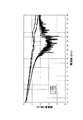
図2は、実施例1、2の高速差動ケーブル1および比較例の高速差動ケーブルに対し、周波数(GHz)を0〜20GHzまで変化させたときの減衰量(dB/m)の変化を示す図である。図2から明らかなように、比較例の高速差動ケーブルでは、周波数が11〜16GHzにかけてサックアウトが発生しているのに対し、実施例1、2の高速差動ケーブル1ではサックアウトの発生を防止できる。 FIG. 2 shows changes in attenuation (dB / m) when the frequency (GHz) is changed from 0 to 20 GHz with respect to the high-
また、例えば周波数が1.0GHz、2.0GHz、3.125GHz、5.0GHz、6.0GHzのとき、比較例の高速差動ケーブルの減衰量は、0.757dB/m、1.001dB/m、1.221dB/m、1.653dB/m、1.845dB/mであるのに対し、実施例1の高速差動ケーブル1の減衰量は、0.603dB/m、0.732dB/m、0.887dB/m、1.164dB/m、1.311dB/m、実施例2の高速差動ケーブル1の減衰量は、0.586dB/m、0.758dB/m、0.967dB/m、1.262dB/m、1.389dB/mとなり、比較例の高速差動ケーブルの減衰量と比べて実施例1、2の高速差動ケーブル1の減衰量の低下を抑えることができる。また、比較例の高速差動ケーブルのスキューが、9.0ps/10mであったのに対し、実施例1の高速差動ケーブル1のスキューは、2ps/10mと小さくすることができる。 For example, when the frequency is 1.0 GHz, 2.0 GHz, 3.125 GHz, 5.0 GHz, 6.0 GHz, the attenuation of the high-speed differential cable of the comparative example is 0.757 dB / m, 1.001 dB / m. 1.221 dB / m, 1.653 dB / m, and 1.845 dB / m, whereas the high-
本発明の高速差動ケーブルは、高速ビットレートで長距離のデータ伝送を行う機器、例えば、コンピュータ、計算機、携帯電話等の電子機器に適用可能であり、更に、自動車、飛行機等の制御回路にも適用可能である。 The high-speed differential cable of the present invention can be applied to devices that perform long-distance data transmission at a high bit rate, for example, electronic devices such as computers, computers, and mobile phones, and further to control circuits such as automobiles and airplanes. Is also applicable.
1 高速作動ケーブル、11 中心導体(内部導体)、12 第1の誘電体層、13 第2の誘電体層、14 ドレイン線、15 シールド層(外部導体層)、15a PET面、15b アルミ面、16 ジャケット(外被)、17 ドレイン線用溝部DESCRIPTION OF
Claims (2)
Translated fromJapanesePriority Applications (6)
| Application Number | Priority Date | Filing Date | Title |
|---|---|---|---|
| JP2009061119AJP5508614B2 (en) | 2009-03-13 | 2009-03-13 | High-speed differential cable |
| US13/256,149US20120024566A1 (en) | 2009-03-13 | 2010-03-10 | High-speed differential cable |
| PCT/JP2010/054476WO2010104203A1 (en) | 2009-03-13 | 2010-03-10 | High-speed differential cable |
| KR1020117019651AKR20110127664A (en) | 2009-03-13 | 2010-03-10 | High speed differential cable |
| EP10750948.1AEP2407979A4 (en) | 2009-03-13 | 2010-03-10 | High-speed differential cable |
| CN2010800118408ACN102349116A (en) | 2009-03-13 | 2010-03-10 | High-speed differential cable |
Applications Claiming Priority (1)
| Application Number | Priority Date | Filing Date | Title |
|---|---|---|---|
| JP2009061119AJP5508614B2 (en) | 2009-03-13 | 2009-03-13 | High-speed differential cable |
Publications (2)
| Publication Number | Publication Date |
|---|---|
| JP2010218741A JP2010218741A (en) | 2010-09-30 |
| JP5508614B2true JP5508614B2 (en) | 2014-06-04 |
Family
ID=42728481
Family Applications (1)
| Application Number | Title | Priority Date | Filing Date |
|---|---|---|---|
| JP2009061119AActiveJP5508614B2 (en) | 2009-03-13 | 2009-03-13 | High-speed differential cable |
Country Status (6)
| Country | Link |
|---|---|
| US (1) | US20120024566A1 (en) |
| EP (1) | EP2407979A4 (en) |
| JP (1) | JP5508614B2 (en) |
| KR (1) | KR20110127664A (en) |
| CN (1) | CN102349116A (en) |
| WO (1) | WO2010104203A1 (en) |
Families Citing this family (26)
| Publication number | Priority date | Publication date | Assignee | Title |
|---|---|---|---|---|
| JP5141660B2 (en)* | 2009-10-14 | 2013-02-13 | 日立電線株式会社 | Differential signal cable, transmission cable using the same, and method for manufacturing differential signal cable |
| JP2012243502A (en)* | 2011-05-18 | 2012-12-10 | Hitachi Cable Fine Tech Ltd | Cable for differential signal transmission and harness using the same |
| JP2013214499A (en)* | 2012-03-07 | 2013-10-17 | Hitachi Cable Ltd | Differential transmission cable and manufacturing method therefor |
| US20140027157A1 (en)* | 2012-07-26 | 2014-01-30 | Futurewei Technologies, Inc. | Device and Method for Printed Circuit Board with Embedded Cable |
| JP6044501B2 (en)* | 2012-10-03 | 2016-12-14 | 日立金属株式会社 | Differential signal transmission cable and method of manufacturing the same |
| US9741465B2 (en)* | 2012-12-31 | 2017-08-22 | Fci Americas Technology Llc | Electrical cable assembly |
| US9966165B2 (en) | 2012-12-31 | 2018-05-08 | Fci Americas Technology Llc | Electrical cable assembly |
| US10171182B2 (en)* | 2015-01-25 | 2019-01-01 | Valens Semiconductor Ltd. | Sending known data to support fast convergence |
| WO2016116912A1 (en)* | 2015-01-25 | 2016-07-28 | Valens Semiconductor Ltd. | Fast adaptive mode-conversion digital canceller |
| JP2018536259A (en)* | 2015-11-17 | 2018-12-06 | レオニ カーベル ゲーエムベーハー | Data cable for high-speed data transmission |
| JP6834732B2 (en)* | 2017-04-12 | 2021-02-24 | 住友電気工業株式会社 | Two-core parallel cable |
| US10304592B1 (en) | 2018-03-19 | 2019-05-28 | Te Connectivity Corporation | Electrical cable |
| US10283238B1 (en) | 2018-03-19 | 2019-05-07 | Te Connectivity Corporation | Electrical cable |
| US10283240B1 (en) | 2018-03-19 | 2019-05-07 | Te Connectivity Corporation | Electrical cable |
| US11069458B2 (en) | 2018-04-13 | 2021-07-20 | TE Connectivity Services Gmbh | Electrical cable |
| US10741308B2 (en) | 2018-05-10 | 2020-08-11 | Te Connectivity Corporation | Electrical cable |
| US10600537B1 (en) | 2018-10-12 | 2020-03-24 | Te Connectivity Corporation | Electrical cable |
| US12087465B2 (en) | 2018-10-12 | 2024-09-10 | Te Connectivity Solutions Gmbh | Electrical cable |
| US10600536B1 (en) | 2018-10-12 | 2020-03-24 | Te Connectivity Corporation | Electrical cable |
| TWI689949B (en)* | 2019-08-28 | 2020-04-01 | 貿聯國際股份有限公司 | Circuit board assembly with high-speed wire |
| US10950367B1 (en) | 2019-09-05 | 2021-03-16 | Te Connectivity Corporation | Electrical cable |
| JP6987824B2 (en)* | 2019-10-25 | 2022-01-05 | 矢崎総業株式会社 | Communication cable and wire harness |
| US11342097B2 (en)* | 2020-08-03 | 2022-05-24 | Dell Products L.P. | Spiral shielding on a high speed cable |
| CN114914028A (en)* | 2021-02-09 | 2022-08-16 | 泰科电子(上海)有限公司 | Cable with a flexible connection |
| CN115376751A (en)* | 2021-05-21 | 2022-11-22 | 泰科电子(上海)有限公司 | Cables and Cable Assemblies |
| CN114649108B (en)* | 2021-11-23 | 2022-11-11 | 三元科技(深圳)有限公司 | Differential high-speed cable, jig for producing differential high-speed cable and process |
Family Cites Families (33)
| Publication number | Priority date | Publication date | Assignee | Title |
|---|---|---|---|---|
| US3896261A (en)* | 1974-04-15 | 1975-07-22 | Belden Corp | Coaxial cable with an undulated drain wire |
| JPS61259407A (en)* | 1985-05-10 | 1986-11-17 | 鈴木 浩一 | Wire with gripper groove |
| JPS6276424U (en)* | 1985-10-31 | 1987-05-16 | ||
| JPS6329413A (en)* | 1986-07-23 | 1988-02-08 | 株式会社フジクラ | Manufacturing method of shielded ribbon cable |
| JPH0741051Y2 (en)* | 1988-09-12 | 1995-09-20 | 古河電気工業株式会社 | Flat cable with shield |
| US5037999A (en)* | 1990-03-08 | 1991-08-06 | W. L. Gore & Associates | Conductively-jacketed coaxial cable |
| US5132491A (en)* | 1991-03-15 | 1992-07-21 | W. L. Gore & Associates, Inc. | Shielded jacketed coaxial cable |
| US5142100A (en)* | 1991-05-01 | 1992-08-25 | Supercomputer Systems Limited Partnership | Transmission line with fluid-permeable jacket |
| US5416268A (en)* | 1993-07-14 | 1995-05-16 | The Whitaker Corporation | Electrical cable with improved shield |
| US5486649A (en)* | 1994-03-17 | 1996-01-23 | Belden Wire & Cable Company | Shielded cable |
| US6204515B1 (en)* | 1999-01-15 | 2001-03-20 | The Dow Chemical Company | Semiconducting polymer field effect transistor |
| JP2001076551A (en)* | 1999-09-07 | 2001-03-23 | Auto Network Gijutsu Kenkyusho:Kk | Shielded cable |
| JP2002304917A (en)* | 2001-04-03 | 2002-10-18 | Auto Network Gijutsu Kenkyusho:Kk | Shielded cable |
| US6444902B1 (en)* | 2001-04-10 | 2002-09-03 | Hon Hai Precision Ind. Co., Ltd. | Electrical cable |
| JP4232942B2 (en)* | 2001-06-01 | 2009-03-04 | 東京特殊電線株式会社 | High-speed differential cable |
| JP2003141944A (en)* | 2001-11-02 | 2003-05-16 | Totoku Electric Co Ltd | Low skew high-speed differential cable |
| JP4044766B2 (en)* | 2002-02-04 | 2008-02-06 | 株式会社オートネットワーク技術研究所 | Flat shielded cable |
| JP4193396B2 (en)* | 2002-02-08 | 2008-12-10 | 住友電気工業株式会社 | Transmission metal cable |
| JP2003297154A (en)* | 2002-04-08 | 2003-10-17 | Fujikura Ltd | Transmission cable |
| CN1220218C (en)* | 2002-07-18 | 2005-09-21 | 东莞蔻玛电子有限公司 | High frequency transmission cable construction |
| JP2004071287A (en)* | 2002-08-05 | 2004-03-04 | Fujikura Ltd | Transmission cable and method of manufacturing the same |
| US6765150B2 (en)* | 2002-08-06 | 2004-07-20 | Angus Hsieh | Signal transmission cable structure |
| JP2004079341A (en)* | 2002-08-19 | 2004-03-11 | Fujikura Ltd | Transmission cable and method of manufacturing the same |
| JP2004087198A (en)* | 2002-08-23 | 2004-03-18 | Fujikura Ltd | Transmission cable and method of manufacturing the same |
| TW590316U (en)* | 2003-03-05 | 2004-06-01 | Je-Jia Jang | Structure for transmission cable |
| US7358436B2 (en)* | 2004-07-27 | 2008-04-15 | Belden Technologies, Inc. | Dual-insulated, fixed together pair of conductors |
| JP2006286480A (en)* | 2005-04-01 | 2006-10-19 | Swcc Showa Device Technology Co Ltd | Transmission cable for differential signal |
| JP2007059323A (en)* | 2005-08-26 | 2007-03-08 | Swcc Showa Device Technology Co Ltd | Differential signal transmission cable |
| US7696437B2 (en)* | 2006-09-21 | 2010-04-13 | Belden Technologies, Inc. | Telecommunications cable |
| TWM324838U (en)* | 2006-09-29 | 2008-01-01 | Transpower Technology Co Ltd | Transmission cable |
| JP2008226564A (en)* | 2007-03-09 | 2008-09-25 | Fujikura Ltd | Differential signal transmission cable |
| US7638210B2 (en)* | 2007-04-16 | 2009-12-29 | Hitachi Global Storage Technologies Netherlands B.V. | Perpendicular magnetic recording medium with exchange-coupled magnetic layers and improved coupling layer |
| TW200908025A (en)* | 2007-06-27 | 2009-02-16 | Sumitomo Electric Industries | High-speed differential transmission cable |
- 2009
- 2009-03-13JPJP2009061119Apatent/JP5508614B2/enactiveActive
- 2010
- 2010-03-10EPEP10750948.1Apatent/EP2407979A4/ennot_activeWithdrawn
- 2010-03-10USUS13/256,149patent/US20120024566A1/ennot_activeAbandoned
- 2010-03-10KRKR1020117019651Apatent/KR20110127664A/ennot_activeWithdrawn
- 2010-03-10CNCN2010800118408Apatent/CN102349116A/enactivePending
- 2010-03-10WOPCT/JP2010/054476patent/WO2010104203A1/enactiveApplication Filing
Also Published As
| Publication number | Publication date |
|---|---|
| EP2407979A4 (en) | 2014-01-08 |
| WO2010104203A1 (en) | 2010-09-16 |
| EP2407979A1 (en) | 2012-01-18 |
| US20120024566A1 (en) | 2012-02-02 |
| CN102349116A (en) | 2012-02-08 |
| JP2010218741A (en) | 2010-09-30 |
| KR20110127664A (en) | 2011-11-25 |
Similar Documents
| Publication | Publication Date | Title |
|---|---|---|
| JP5508614B2 (en) | High-speed differential cable | |
| JP6834732B2 (en) | Two-core parallel cable | |
| US8487184B2 (en) | Communication cable | |
| WO2013069755A1 (en) | High-speed signal transmission cable | |
| CN106067347B (en) | Multi-core cable | |
| JP2011222262A (en) | Shield cable | |
| JP5330888B2 (en) | High-speed differential cable | |
| JP7327421B2 (en) | Two core parallel cable | |
| TWM497332U (en) | Multi-core cable | |
| CN102110498B (en) | Small-diameter coaxial cable | |
| US20180268965A1 (en) | Data cable for high speed data transmissions and method of manufacturing the data cable | |
| JP2014078339A (en) | Multi-pair differential signal transmission cable | |
| JP5092213B2 (en) | 2-core balanced cable | |
| JP2015185527A (en) | 2-core parallel wire | |
| JP2010092805A (en) | Extruded flat cable for differential transmission | |
| JP2007280762A (en) | Non-halogen coaxial cable and multi-core cable using the same | |
| CN215577900U (en) | Cable and cable assembly | |
| WO2011074693A1 (en) | High-speed differential quad cable | |
| JP5443794B2 (en) | High-speed differential cable | |
| JP2003187649A (en) | Semi-flexible coaxial cable | |
| JP2010073463A (en) | High-speed differential cable | |
| JP6898062B2 (en) | Differential transmission cable and multi-pair differential transmission cable | |
| JP2006351414A (en) | coaxial cable | |
| JP2003031045A (en) | 2-core parallel micro coaxial cable with vertical deposition tape | |
| CN114914018A (en) | Cables and Cable Assemblies |
Legal Events
| Date | Code | Title | Description |
|---|---|---|---|
| A621 | Written request for application examination | Free format text:JAPANESE INTERMEDIATE CODE: A621 Effective date:20120306 | |
| A131 | Notification of reasons for refusal | Free format text:JAPANESE INTERMEDIATE CODE: A131 Effective date:20130827 | |
| A521 | Written amendment | Free format text:JAPANESE INTERMEDIATE CODE: A523 Effective date:20131024 | |
| A131 | Notification of reasons for refusal | Free format text:JAPANESE INTERMEDIATE CODE: A131 Effective date:20131203 | |
| A521 | Written amendment | Free format text:JAPANESE INTERMEDIATE CODE: A523 Effective date:20140122 | |
| TRDD | Decision of grant or rejection written | ||
| A01 | Written decision to grant a patent or to grant a registration (utility model) | Free format text:JAPANESE INTERMEDIATE CODE: A01 Effective date:20140318 | |
| A61 | First payment of annual fees (during grant procedure) | Free format text:JAPANESE INTERMEDIATE CODE: A61 Effective date:20140321 | |
| R150 | Certificate of patent or registration of utility model | Ref document number:5508614 Country of ref document:JP Free format text:JAPANESE INTERMEDIATE CODE: R150 | |
| R250 | Receipt of annual fees | Free format text:JAPANESE INTERMEDIATE CODE: R250 | |
| R250 | Receipt of annual fees | Free format text:JAPANESE INTERMEDIATE CODE: R250 | |
| R250 | Receipt of annual fees | Free format text:JAPANESE INTERMEDIATE CODE: R250 |