JP5506052B2 - Vehicle charging device - Google Patents
Vehicle charging deviceDownload PDFInfo
- Publication number
- JP5506052B2 JP5506052B2JP2010292008AJP2010292008AJP5506052B2JP 5506052 B2JP5506052 B2JP 5506052B2JP 2010292008 AJP2010292008 AJP 2010292008AJP 2010292008 AJP2010292008 AJP 2010292008AJP 5506052 B2JP5506052 B2JP 5506052B2
- Authority
- JP
- Japan
- Prior art keywords
- charging
- vehicle
- control signal
- control
- charging control
- Prior art date
- Legal status (The legal status is an assumption and is not a legal conclusion. Google has not performed a legal analysis and makes no representation as to the accuracy of the status listed.)
- Active
Links
Images


Classifications
- B—PERFORMING OPERATIONS; TRANSPORTING
- B60—VEHICLES IN GENERAL
- B60L—PROPULSION OF ELECTRICALLY-PROPELLED VEHICLES; SUPPLYING ELECTRIC POWER FOR AUXILIARY EQUIPMENT OF ELECTRICALLY-PROPELLED VEHICLES; ELECTRODYNAMIC BRAKE SYSTEMS FOR VEHICLES IN GENERAL; MAGNETIC SUSPENSION OR LEVITATION FOR VEHICLES; MONITORING OPERATING VARIABLES OF ELECTRICALLY-PROPELLED VEHICLES; ELECTRIC SAFETY DEVICES FOR ELECTRICALLY-PROPELLED VEHICLES
- B60L53/00—Methods of charging batteries, specially adapted for electric vehicles; Charging stations or on-board charging equipment therefor; Exchange of energy storage elements in electric vehicles
- B60L53/60—Monitoring or controlling charging stations
- B60L53/62—Monitoring or controlling charging stations in response to charging parameters, e.g. current, voltage or electrical charge
- B—PERFORMING OPERATIONS; TRANSPORTING
- B60—VEHICLES IN GENERAL
- B60L—PROPULSION OF ELECTRICALLY-PROPELLED VEHICLES; SUPPLYING ELECTRIC POWER FOR AUXILIARY EQUIPMENT OF ELECTRICALLY-PROPELLED VEHICLES; ELECTRODYNAMIC BRAKE SYSTEMS FOR VEHICLES IN GENERAL; MAGNETIC SUSPENSION OR LEVITATION FOR VEHICLES; MONITORING OPERATING VARIABLES OF ELECTRICALLY-PROPELLED VEHICLES; ELECTRIC SAFETY DEVICES FOR ELECTRICALLY-PROPELLED VEHICLES
- B60L50/00—Electric propulsion with power supplied within the vehicle
- B60L50/50—Electric propulsion with power supplied within the vehicle using propulsion power supplied by batteries or fuel cells
- B—PERFORMING OPERATIONS; TRANSPORTING
- B60—VEHICLES IN GENERAL
- B60L—PROPULSION OF ELECTRICALLY-PROPELLED VEHICLES; SUPPLYING ELECTRIC POWER FOR AUXILIARY EQUIPMENT OF ELECTRICALLY-PROPELLED VEHICLES; ELECTRODYNAMIC BRAKE SYSTEMS FOR VEHICLES IN GENERAL; MAGNETIC SUSPENSION OR LEVITATION FOR VEHICLES; MONITORING OPERATING VARIABLES OF ELECTRICALLY-PROPELLED VEHICLES; ELECTRIC SAFETY DEVICES FOR ELECTRICALLY-PROPELLED VEHICLES
- B60L53/00—Methods of charging batteries, specially adapted for electric vehicles; Charging stations or on-board charging equipment therefor; Exchange of energy storage elements in electric vehicles
- B60L53/10—Methods of charging batteries, specially adapted for electric vehicles; Charging stations or on-board charging equipment therefor; Exchange of energy storage elements in electric vehicles characterised by the energy transfer between the charging station and the vehicle
- B60L53/14—Conductive energy transfer
- B60L53/18—Cables specially adapted for charging electric vehicles
- B—PERFORMING OPERATIONS; TRANSPORTING
- B60—VEHICLES IN GENERAL
- B60L—PROPULSION OF ELECTRICALLY-PROPELLED VEHICLES; SUPPLYING ELECTRIC POWER FOR AUXILIARY EQUIPMENT OF ELECTRICALLY-PROPELLED VEHICLES; ELECTRODYNAMIC BRAKE SYSTEMS FOR VEHICLES IN GENERAL; MAGNETIC SUSPENSION OR LEVITATION FOR VEHICLES; MONITORING OPERATING VARIABLES OF ELECTRICALLY-PROPELLED VEHICLES; ELECTRIC SAFETY DEVICES FOR ELECTRICALLY-PROPELLED VEHICLES
- B60L53/00—Methods of charging batteries, specially adapted for electric vehicles; Charging stations or on-board charging equipment therefor; Exchange of energy storage elements in electric vehicles
- B60L53/30—Constructional details of charging stations
- B—PERFORMING OPERATIONS; TRANSPORTING
- B60—VEHICLES IN GENERAL
- B60L—PROPULSION OF ELECTRICALLY-PROPELLED VEHICLES; SUPPLYING ELECTRIC POWER FOR AUXILIARY EQUIPMENT OF ELECTRICALLY-PROPELLED VEHICLES; ELECTRODYNAMIC BRAKE SYSTEMS FOR VEHICLES IN GENERAL; MAGNETIC SUSPENSION OR LEVITATION FOR VEHICLES; MONITORING OPERATING VARIABLES OF ELECTRICALLY-PROPELLED VEHICLES; ELECTRIC SAFETY DEVICES FOR ELECTRICALLY-PROPELLED VEHICLES
- B60L53/00—Methods of charging batteries, specially adapted for electric vehicles; Charging stations or on-board charging equipment therefor; Exchange of energy storage elements in electric vehicles
- B60L53/60—Monitoring or controlling charging stations
- B60L53/64—Optimising energy costs, e.g. responding to electricity rates
- B—PERFORMING OPERATIONS; TRANSPORTING
- B60—VEHICLES IN GENERAL
- B60L—PROPULSION OF ELECTRICALLY-PROPELLED VEHICLES; SUPPLYING ELECTRIC POWER FOR AUXILIARY EQUIPMENT OF ELECTRICALLY-PROPELLED VEHICLES; ELECTRODYNAMIC BRAKE SYSTEMS FOR VEHICLES IN GENERAL; MAGNETIC SUSPENSION OR LEVITATION FOR VEHICLES; MONITORING OPERATING VARIABLES OF ELECTRICALLY-PROPELLED VEHICLES; ELECTRIC SAFETY DEVICES FOR ELECTRICALLY-PROPELLED VEHICLES
- B60L53/00—Methods of charging batteries, specially adapted for electric vehicles; Charging stations or on-board charging equipment therefor; Exchange of energy storage elements in electric vehicles
- B60L53/60—Monitoring or controlling charging stations
- B60L53/67—Controlling two or more charging stations
- H—ELECTRICITY
- H01—ELECTRIC ELEMENTS
- H01M—PROCESSES OR MEANS, e.g. BATTERIES, FOR THE DIRECT CONVERSION OF CHEMICAL ENERGY INTO ELECTRICAL ENERGY
- H01M10/00—Secondary cells; Manufacture thereof
- H01M10/42—Methods or arrangements for servicing or maintenance of secondary cells or secondary half-cells
- H01M10/44—Methods for charging or discharging
- H—ELECTRICITY
- H02—GENERATION; CONVERSION OR DISTRIBUTION OF ELECTRIC POWER
- H02J—CIRCUIT ARRANGEMENTS OR SYSTEMS FOR SUPPLYING OR DISTRIBUTING ELECTRIC POWER; SYSTEMS FOR STORING ELECTRIC ENERGY
- H02J5/00—Circuit arrangements for transfer of electric power between AC networks and DC networks
- H—ELECTRICITY
- H02—GENERATION; CONVERSION OR DISTRIBUTION OF ELECTRIC POWER
- H02J—CIRCUIT ARRANGEMENTS OR SYSTEMS FOR SUPPLYING OR DISTRIBUTING ELECTRIC POWER; SYSTEMS FOR STORING ELECTRIC ENERGY
- H02J7/00—Circuit arrangements for charging or depolarising batteries or for supplying loads from batteries
- H02J7/00032—Circuit arrangements for charging or depolarising batteries or for supplying loads from batteries characterised by data exchange
- H02J7/00036—Charger exchanging data with battery
- H—ELECTRICITY
- H02—GENERATION; CONVERSION OR DISTRIBUTION OF ELECTRIC POWER
- H02J—CIRCUIT ARRANGEMENTS OR SYSTEMS FOR SUPPLYING OR DISTRIBUTING ELECTRIC POWER; SYSTEMS FOR STORING ELECTRIC ENERGY
- H02J7/00—Circuit arrangements for charging or depolarising batteries or for supplying loads from batteries
- H02J7/00047—Circuit arrangements for charging or depolarising batteries or for supplying loads from batteries with provisions for charging different types of batteries
- H—ELECTRICITY
- H02—GENERATION; CONVERSION OR DISTRIBUTION OF ELECTRIC POWER
- H02J—CIRCUIT ARRANGEMENTS OR SYSTEMS FOR SUPPLYING OR DISTRIBUTING ELECTRIC POWER; SYSTEMS FOR STORING ELECTRIC ENERGY
- H02J7/00—Circuit arrangements for charging or depolarising batteries or for supplying loads from batteries
- H02J7/02—Circuit arrangements for charging or depolarising batteries or for supplying loads from batteries for charging batteries from AC mains by converters
- H02J7/04—Regulation of charging current or voltage
- H—ELECTRICITY
- H02—GENERATION; CONVERSION OR DISTRIBUTION OF ELECTRIC POWER
- H02J—CIRCUIT ARRANGEMENTS OR SYSTEMS FOR SUPPLYING OR DISTRIBUTING ELECTRIC POWER; SYSTEMS FOR STORING ELECTRIC ENERGY
- H02J2310/00—The network for supplying or distributing electric power characterised by its spatial reach or by the load
- H02J2310/40—The network being an on-board power network, i.e. within a vehicle
- H02J2310/48—The network being an on-board power network, i.e. within a vehicle for electric vehicles [EV] or hybrid vehicles [HEV]
- Y—GENERAL TAGGING OF NEW TECHNOLOGICAL DEVELOPMENTS; GENERAL TAGGING OF CROSS-SECTIONAL TECHNOLOGIES SPANNING OVER SEVERAL SECTIONS OF THE IPC; TECHNICAL SUBJECTS COVERED BY FORMER USPC CROSS-REFERENCE ART COLLECTIONS [XRACs] AND DIGESTS
- Y02—TECHNOLOGIES OR APPLICATIONS FOR MITIGATION OR ADAPTATION AGAINST CLIMATE CHANGE
- Y02E—REDUCTION OF GREENHOUSE GAS [GHG] EMISSIONS, RELATED TO ENERGY GENERATION, TRANSMISSION OR DISTRIBUTION
- Y02E60/00—Enabling technologies; Technologies with a potential or indirect contribution to GHG emissions mitigation
- Y02E60/10—Energy storage using batteries
- Y—GENERAL TAGGING OF NEW TECHNOLOGICAL DEVELOPMENTS; GENERAL TAGGING OF CROSS-SECTIONAL TECHNOLOGIES SPANNING OVER SEVERAL SECTIONS OF THE IPC; TECHNICAL SUBJECTS COVERED BY FORMER USPC CROSS-REFERENCE ART COLLECTIONS [XRACs] AND DIGESTS
- Y02—TECHNOLOGIES OR APPLICATIONS FOR MITIGATION OR ADAPTATION AGAINST CLIMATE CHANGE
- Y02T—CLIMATE CHANGE MITIGATION TECHNOLOGIES RELATED TO TRANSPORTATION
- Y02T10/00—Road transport of goods or passengers
- Y02T10/60—Other road transportation technologies with climate change mitigation effect
- Y02T10/70—Energy storage systems for electromobility, e.g. batteries
- Y—GENERAL TAGGING OF NEW TECHNOLOGICAL DEVELOPMENTS; GENERAL TAGGING OF CROSS-SECTIONAL TECHNOLOGIES SPANNING OVER SEVERAL SECTIONS OF THE IPC; TECHNICAL SUBJECTS COVERED BY FORMER USPC CROSS-REFERENCE ART COLLECTIONS [XRACs] AND DIGESTS
- Y02—TECHNOLOGIES OR APPLICATIONS FOR MITIGATION OR ADAPTATION AGAINST CLIMATE CHANGE
- Y02T—CLIMATE CHANGE MITIGATION TECHNOLOGIES RELATED TO TRANSPORTATION
- Y02T10/00—Road transport of goods or passengers
- Y02T10/60—Other road transportation technologies with climate change mitigation effect
- Y02T10/7072—Electromobility specific charging systems or methods for batteries, ultracapacitors, supercapacitors or double-layer capacitors
- Y—GENERAL TAGGING OF NEW TECHNOLOGICAL DEVELOPMENTS; GENERAL TAGGING OF CROSS-SECTIONAL TECHNOLOGIES SPANNING OVER SEVERAL SECTIONS OF THE IPC; TECHNICAL SUBJECTS COVERED BY FORMER USPC CROSS-REFERENCE ART COLLECTIONS [XRACs] AND DIGESTS
- Y02—TECHNOLOGIES OR APPLICATIONS FOR MITIGATION OR ADAPTATION AGAINST CLIMATE CHANGE
- Y02T—CLIMATE CHANGE MITIGATION TECHNOLOGIES RELATED TO TRANSPORTATION
- Y02T10/00—Road transport of goods or passengers
- Y02T10/80—Technologies aiming to reduce greenhouse gasses emissions common to all road transportation technologies
- Y02T10/92—Energy efficient charging or discharging systems for batteries, ultracapacitors, supercapacitors or double-layer capacitors specially adapted for vehicles
- Y—GENERAL TAGGING OF NEW TECHNOLOGICAL DEVELOPMENTS; GENERAL TAGGING OF CROSS-SECTIONAL TECHNOLOGIES SPANNING OVER SEVERAL SECTIONS OF THE IPC; TECHNICAL SUBJECTS COVERED BY FORMER USPC CROSS-REFERENCE ART COLLECTIONS [XRACs] AND DIGESTS
- Y02—TECHNOLOGIES OR APPLICATIONS FOR MITIGATION OR ADAPTATION AGAINST CLIMATE CHANGE
- Y02T—CLIMATE CHANGE MITIGATION TECHNOLOGIES RELATED TO TRANSPORTATION
- Y02T90/00—Enabling technologies or technologies with a potential or indirect contribution to GHG emissions mitigation
- Y02T90/10—Technologies relating to charging of electric vehicles
- Y02T90/12—Electric charging stations
- Y—GENERAL TAGGING OF NEW TECHNOLOGICAL DEVELOPMENTS; GENERAL TAGGING OF CROSS-SECTIONAL TECHNOLOGIES SPANNING OVER SEVERAL SECTIONS OF THE IPC; TECHNICAL SUBJECTS COVERED BY FORMER USPC CROSS-REFERENCE ART COLLECTIONS [XRACs] AND DIGESTS
- Y02—TECHNOLOGIES OR APPLICATIONS FOR MITIGATION OR ADAPTATION AGAINST CLIMATE CHANGE
- Y02T—CLIMATE CHANGE MITIGATION TECHNOLOGIES RELATED TO TRANSPORTATION
- Y02T90/00—Enabling technologies or technologies with a potential or indirect contribution to GHG emissions mitigation
- Y02T90/10—Technologies relating to charging of electric vehicles
- Y02T90/14—Plug-in electric vehicles
- Y—GENERAL TAGGING OF NEW TECHNOLOGICAL DEVELOPMENTS; GENERAL TAGGING OF CROSS-SECTIONAL TECHNOLOGIES SPANNING OVER SEVERAL SECTIONS OF THE IPC; TECHNICAL SUBJECTS COVERED BY FORMER USPC CROSS-REFERENCE ART COLLECTIONS [XRACs] AND DIGESTS
- Y02—TECHNOLOGIES OR APPLICATIONS FOR MITIGATION OR ADAPTATION AGAINST CLIMATE CHANGE
- Y02T—CLIMATE CHANGE MITIGATION TECHNOLOGIES RELATED TO TRANSPORTATION
- Y02T90/00—Enabling technologies or technologies with a potential or indirect contribution to GHG emissions mitigation
- Y02T90/10—Technologies relating to charging of electric vehicles
- Y02T90/16—Information or communication technologies improving the operation of electric vehicles
- Y02T90/167—Systems integrating technologies related to power network operation and communication or information technologies for supporting the interoperability of electric or hybrid vehicles, i.e. smartgrids as interface for battery charging of electric vehicles [EV] or hybrid vehicles [HEV]
- Y—GENERAL TAGGING OF NEW TECHNOLOGICAL DEVELOPMENTS; GENERAL TAGGING OF CROSS-SECTIONAL TECHNOLOGIES SPANNING OVER SEVERAL SECTIONS OF THE IPC; TECHNICAL SUBJECTS COVERED BY FORMER USPC CROSS-REFERENCE ART COLLECTIONS [XRACs] AND DIGESTS
- Y04—INFORMATION OR COMMUNICATION TECHNOLOGIES HAVING AN IMPACT ON OTHER TECHNOLOGY AREAS
- Y04S—SYSTEMS INTEGRATING TECHNOLOGIES RELATED TO POWER NETWORK OPERATION, COMMUNICATION OR INFORMATION TECHNOLOGIES FOR IMPROVING THE ELECTRICAL POWER GENERATION, TRANSMISSION, DISTRIBUTION, MANAGEMENT OR USAGE, i.e. SMART GRIDS
- Y04S30/00—Systems supporting specific end-user applications in the sector of transportation
- Y04S30/10—Systems supporting the interoperability of electric or hybrid vehicles
- Y04S30/14—Details associated with the interoperability, e.g. vehicle recognition, authentication, identification or billing
Landscapes
- Engineering & Computer Science (AREA)
- Power Engineering (AREA)
- Mechanical Engineering (AREA)
- Transportation (AREA)
- Chemical Kinetics & Catalysis (AREA)
- Electrochemistry (AREA)
- General Chemical & Material Sciences (AREA)
- Chemical & Material Sciences (AREA)
- Manufacturing & Machinery (AREA)
- Life Sciences & Earth Sciences (AREA)
- Sustainable Development (AREA)
- Sustainable Energy (AREA)
- Charge And Discharge Circuits For Batteries Or The Like (AREA)
- Electric Propulsion And Braking For Vehicles (AREA)
- Remote Monitoring And Control Of Power-Distribution Networks (AREA)
- Secondary Cells (AREA)
Description
Translated fromJapanese 本発明は、プラグインハイブリッドカーや電気自動車等の車載電池を備えた車両のうち、モード3の充電システムに対応した車両に対して充電を行うために用いられる車両用充電装置に関するものである。 The present invention relates to a vehicular charging device used for charging a vehicle corresponding to a charging system of
今後急速な普及が予想されるプラグインハイブリッドカーや電気自動車等の充電システムについては、米国のSAE(ソサエティ・オブ・オートモーティブ・エンジニアズ)と日本のJEVA(現JARI日本自動車研究所)が標準システムを定めている。この標準システム中にも複数のモードが設定されており、例えば地上側の設備として充電ケーブルと漏電遮断手段のみが要求されるモード(モード1)や、地上側の設備としてさらに車両側の充電制御回路に対して充電制御信号(CPLT)を送る充電制御手段を含む制御手段が要求されるモード(モード3)がある。これら標準システムの内容については、特許文献1の背景技術の欄に記載されている。 Standard charging systems for plug-in hybrid cars and electric vehicles that are expected to spread rapidly in the future are SAE (Society of Automotive Engineers) in the US and JEVA (currently JARI Japan Automobile Research Institute) in Japan. Is stipulated. A plurality of modes are also set in this standard system. For example, a mode (mode 1) in which only a charging cable and a leakage breaker are required as ground side equipment, and a vehicle side charge control as ground side equipment. There is a mode (mode 3) in which control means including charge control means for sending a charge control signal (CPLT) to the circuit is required. The contents of these standard systems are described in the background art section of Patent Document 1.
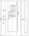
このようなモードのうちのモード3を採用した車両の場合には、車両側の充電制御回路によって充電ケーブルの接続状況や車載電池の充電状態などがチェックされたうえで充電が開始される。 In the case of a
図4には、モード3の車両30に対応する車両用充電装置20おける充電開始制御に関する回路図を示し、図5には、充電状況ごとに図4のA点の電位(充電制御信号)の変化を示すグラフを示している。図4の回路図において、モード3の車両30に充電ケーブル1を未接続の状態では、車両用充電装置20のA点の電位(充電制御信号)が12Vとなるようにしておく。
充電ケーブル1は充電電路を構成する電源線1aと、充電制御信号を送信する情報線1bと、アース線1cより構成される。充電ケーブル1を車両30に接続すると、車両側の充電制御回路6の抵抗R2が抵抗R1と直列に接続されることとなるから分圧され、A点の電位(充電制御信号)は9Vとなる。充電制御部7は、12Vから9Vへの電位の変化によって、モード3の車両30の充電ケーブル1が接続されたことを検知し、その後、充電制御部7が発振器10を発振させて9V発振の状態となる。これによってパルス状の9Vが車両側に入り、車両側の充電開始制御回路6が受電許可スイッチ12をオンとする。この結果、抵抗R3の抵抗分圧によってA点の電位(充電制御信号)は6V発振に変化し、受電準備が完了となる。充電制御部7はこの状態においてリレー5にオン信号を出力し、充電電路2に充電電流が流れて車両側の充電器を介して車載電池4への充電が開始される。FIG. 4 shows a circuit diagram relating to charge start control in the
The charging cable 1 includes a
なお、上記した充電開始制御は車両側では、駆動以外に使用される補助バッテリーを用いて行われるが、車種によっては充電ケーブル1の接続を検知した後の所定時間内に充電が開始されないと、車両30の補助バッテリーのバッテリー上がりを防止するため車両側の充電制御回路6への電源供給を停止するスリープモード機能を備えたものがある。
スリープモードの状態の車両に再度充電を開始しようとする場合、スリープモードを解除するため、作業者は物理的な充電ケーブル1の接続解除及び再接続する必要がある。The above-described charging start control is performed on the vehicle side using an auxiliary battery that is used other than driving, but depending on the vehicle model, if charging is not started within a predetermined time after the connection of the charging cable 1 is detected, Some have a sleep mode function for stopping the power supply to the
When attempting to start charging the vehicle in the sleep mode again, the worker needs to disconnect and reconnect the physical charging cable 1 in order to cancel the sleep mode.
一方、車両用充電装置20には、電気料金の安い深夜電力を利用して車両30を充電するために、充電ケーブル1を接続後の所定時間経過後に充電を開始できるタイマ制御機能が設けたり、或いは、集合住宅等で複数台の車両を交互に充電していくために、充電開始や充電停止を交互に繰り返す機能が設けたりすることが予定される。しかし、前記スリープモード機能を備えた車両30を車両用充電装置20に接続すると、上記と同様の問題が生ずるため、事実上、これらの機能が使用できないという問題があった。 On the other hand, the
本発明の目的は前記問題を解決し、車両用充電装置の制御によって、充電ケーブルを車両に接続直後に開始されないタイマ制御機能や、一時的に充電を停止させる機能を備えた車両用充電装置にスリープモード機能を備えた車両を車両用充電装置に接続した場合でも、作業者による物理的な充電ケーブルの接続解除及び再接続することなく、タイマ制御機能や一時的な充電停止及び再開させる制御機能を設けることができる車両用充電装置を提供することである。 The object of the present invention is to solve the above-mentioned problems and to provide a vehicle charging device having a timer control function that does not start immediately after the charging cable is connected to the vehicle or a function that temporarily stops charging by controlling the vehicle charging device. Even when a vehicle equipped with a sleep mode function is connected to the vehicle charging device, the timer control function and the control function for temporarily stopping and resuming charging without disconnecting and reconnecting the physical charging cable by the operator It is providing the vehicle charging device which can be provided.
上記課題を解決するためになされた本発明の車両用充電装置は、充電ケーブルを介して充電制御回路を搭載している車両への充電を行う車両用充電装置であって、車両側の充電制御回路に対し充電制御信号を送信して、車両への充電を制御する充電制御手段と、該充電制御信号の送信を制限する充電制御信号送信制限手段と、充電制御信号の送信制限が解除された際、充電制御信号を強制的リセットするリセット手段と、を備えることを特徴とするものである。 The vehicle charging device of the present invention made to solve the above problems is a vehicle charging device that charges a vehicle equipped with a charging control circuit via a charging cable, and is a vehicle-side charging control. The charging control signal for controlling the charging to the vehicle by transmitting the charging control signal to the circuit, the charging control signal transmission limiting unit for limiting the transmission of the charging control signal, and the transmission limitation of the charging control signal are released. And a reset means for forcibly resetting the charge control signal.
請求項2記載の発明は、請求項1記載の車両用充電装置において、充電制御信号送信制限手段は、充電ケーブルを介して車両と接続後、制限手段による制御により車両側の充電制御回路に対する充電制御信号の送信を制限する機能を備えることを特徴とするものである。 According to a second aspect of the present invention, in the charging device for a vehicle according to the first aspect, the charging control signal transmission restricting means is connected to the vehicle via the charging cable and then charged to the charging control circuit on the vehicle side by the control of the restricting means. It has a function of limiting transmission of control signals.
請求項3記載の発明は、請求項2記載の車両用充電装置において、制限手段が、設定時刻に充電を許可するタイマ制御手段であることを特徴とするものである。 According to a third aspect of the present invention, in the vehicle charging device according to the second aspect, the limiting means is a timer control means that permits charging at a set time.
請求項4の発明は、請求項2記載の車両用充電装置において、車両を交互に充電していくために、充電開始や充電停止を交互に繰り返す一時的な充電停止及び再開させる制御機能を構成する制御用コンピュータであることを特徴とするものである。 According to a fourth aspect of the present invention, in the vehicle charging apparatus according to the second aspect, in order to charge the vehicle alternately, a control function for temporarily stopping and resuming charging that repeatedly starts and stops charging is configured. It is the control computer which performs.
請求項5の発明に係る本発明の車両用充電装置は、充電ケーブルを介して充電制御回路を搭載している車両への充電を行う車両用充電装置であって、車両側の充電制御回路に対し充電制御信号を送信して、車両への充電を制御する充電制御手段と、該充電制御信号の送信を制限する充電制御信号送信制限手段と、該車両用充電装置に電力を供給する交流電源が停電し、その後復電した時に充電制御信号を強制的にリセットするリセット手段と、を備えることを特徴とすることを特徴とするものである。According to a fifth aspect of the present invention, there is provided a vehicular charging apparatus according to the present invention, which is a vehicular charging apparatus that charges a vehicle equipped with a charging control circuit via a charging cable. Charging control means for controlling charging to the vehicle by transmitting a charging control signal, charging control signal transmission limiting means for restricting transmission of the charging control signal, andAC power supply for supplying power to the vehicle charging device And a resetting means for forcibly resetting the charge control signal whenpower is restored after that .
本発明に係る車両用充電装置では、車両側の充電制御回路に対し充電制御信号を送信して、車両への充電を制御する充電制御手段と、該充電制御信号の送信を制限する充電制御信号送信制限手段と、充電制御信号の送信制限が解除された際、充電制御信号を強制的にリセットするリセット手段をと、備える構成により、タイマ制御機能や一時的な充電停止及び再開させる制御機能による充電制御信号の送信制限が解除されると、速やかに充電制御信号が強制的にリセットされるため、スリープモード機能を備えた車両に対しても、作業者による物理的な充電ケーブルの接続解除及び再接続することなく、タイマ制御や一時的な充電停止及び再開させる制御による充電を可能とした。 In the vehicle charging device according to the present invention, a charging control signal for controlling charging to the vehicle by transmitting a charging control signal to the charging control circuit on the vehicle side, and a charging control signal for limiting transmission of the charging control signal With a configuration including a transmission limiting unit and a reset unit that forcibly resets the charging control signal when the transmission limitation of the charging control signal is released, a timer control function or a control function that temporarily stops and restarts charging When the restriction on transmission of the charge control signal is released, the charge control signal is forcibly reset immediately. Charging by timer control or temporary charging stop and restart control is possible without reconnection.
以下に本発明の実施形態を説明する。
図1は、モード3(充電時に車両と接続される充電装置側の制御手段として、車両側の充電制御回路6に対して充電制御信号(CPLT)を送る充電制御手段を含むことを要求されるモード)対応型の車両用充電装置20と車両30とを充電ケーブル1によって接続した状態を示すブロック図である。充電ケーブル1は電源を供給する電源線1aと、充電制御信号を送信する情報線1bと、アース線1cより構成されている。電源線1aは車両用充電装置20内部で漏電遮断器(ELB)を備えた充電電路2に接続されていて、交流電源3から供給される電力を、充電ケーブル1を経由して車両側の充電器を介して車載電池4に充電するものである。充電電路2には通電をオン・オフ制御するためのリレー5が設けられている。Embodiments of the present invention will be described below.
FIG. 1 is required to include mode 3 (charge control means for sending a charge control signal (CPLT) to the
7は充電装置の充電制御部であり、交流−直流変換手段である電源8を備えている。
この充電制御部7には、発振器(オシレータ)10と抵抗R1を介して、充電制御信号端子11が設けられている。その電圧(A点の電圧)は充電制御部7に入力される。
車両側の充電制御回路6との間で充電制御信号(CPLT)をやり取りする発振器10は、予め定められたデューティ比(パルス幅/パルス周期)の充電制御信号を発振する。充電制御信号のデューティ比は充電制御装置の充電容量や充電ケーブルの種類等によって定められるものである。
車両側の充電制御信号端子11’とアース端子14’との間には、抵抗R3と直列の受電許可スイッチ12と、抵抗R2と、コンデンサ13とが互いに並列に接続されている。この受電許可スイッチ12は車両側の充電制御回路6によって制御されるものである。なお、デューティ比(パルス幅/パルス周期)が大きいほど大きな充電電流が供給可能であることを意味しており、車両側の充電制御回路6が発振器10から出力される充電制御信号のデューティ比を読み取り、車載電池4への充電電流を制御する。The
An
Between the charge
充電制御部7は、図2に示すように、車両側の充電制御回路6に対し充電制御信号を送信して、車両30への充電開始制御を行う充電制御手段71と、該充電制御信号の送信を制限する充電制御信号送信制限手段72と、充電制御信号を強制的にリセットするリセット手段73を備えている。 As shown in FIG. 2, the
本実施形態の車両用充電装置では、充電ケーブル1を車両30に接続していない場合、充電制御手段71の送信する充電制御信号は、充電制御端子11の電圧が12Vとなるように調整されており、充電ケーブル1をモード3対応の車両30に接続すると、車両側の充電制御回路6に設けた抵抗R2によって分圧され、充電制御端子11の電圧は9Vに低下する。 In the vehicle charging device of the present embodiment, when the charging cable 1 is not connected to the
充電制御部7は、該12Vから9Vへの電位の変化によって、モード3の車両30の充電ケーブル1が接続されたことを検知し、その後、充電制御部7が発振器10を発振させて9V発振の状態となる。9Vで発振した充電制御信号が車両側に入ると、車両側の充電制御回路6に内蔵された充電許可スイッチ12がオンとなる。その結果、充電制御信号の電圧は車両側の充電制御回路6に内蔵されている別の抵抗R3によって分圧されて6V発振となり、受電準備完了となる。 The
この状態において充電制御部7は充電電路2を開閉するリレー5にオン信号を出力し、車両側の充電制御回路6はパルス信号より供給可能な電流値の範囲内で車載電池4への充電が開始される。なおパルスの周波数はスタンドにより異なるが、電圧やデューティ比は規格化されている。また、車両用充電制御装置は、6V発振のパルス信号により充電が開始された旨の表示を行う。 In this state, the charging
図2に示すように、充電制御部7の充電制御手段71には充電制御信号送信制限手段72が接続されている。また、充電制御信号送信制限手段72は、充電ケーブル接続後であって、設定された時刻に充電を開始する車両用充電装置20に内蔵したタイマ制御手段等からなる制限手段16から発信される制御信号により、充電制御手段71に対して制限信号を出力又は解除する制御を行う。すなわち、充電制御信号送信制限手段72が充電制御手段71に対して制限信号を出力している状態では、充電制御手段71による充電制御信号の送信がされず、車両30は充電を開始することができない。
例えば、充電制御信号送信制限手段72は、タイマ制御手段によって充電開始時刻になるまでは、「充電禁止」の制御信号が出力されているため、充電制御手段71に対して制限信号を出力している。これにより、充電制御手段71は12Vから9Vへの電位の変化によって、モード3の車両30の充電ケーブル1が接続されたことを検知しても、発振器10を発振させることができない。
充電開始時刻になった時点でタイマ制御手段は「充電許可」の制御信号を出力するため充電制御信号送信制限手段72は、充電制御手段71に対して制限信号を解除する。これにより、充電制御手段71は発振器10を発振させることができ充電が開始される。As shown in FIG. 2, a charging control signal
For example, the charging control signal
When the charging start time is reached, the timer control means outputs a “charge permission” control signal, so that the charge control signal transmission restriction means 72 releases the restriction signal to the charge control means 71. Thereby, the charging control means 71 can oscillate the
なお、制限手段16としては、車両を交互に充電していくために充電開始や充電停止を交互に繰り返す一時的な充電停止及び再開させる制御を行うシステムの制御コンピュータであってもよい。例えば、複数の車両用充電装置が接続された充電システムであって、同時に複数の車両に充電を行うことが可能である。充電する車両の数が少ない時には、連続して充電を行うことが可能なものである。車両の台数が多く契約電力を超える場合には一部の車両に対して一時的に充電を停止させることにより、契約電力を超えないように、制御コンピュータによって、各車両用の充電装置の充電を制御している。
また、太陽光発電等の電源を充電に利用する場合には、発電量が日射量により変化するため、発電量の変化に応じて、制御コンピュータが充電を一時的に停止させ、又は再開させる制御を行うことが予定されている。
この制御用コンピュータからの「充電禁止」の制御信号を各車両用充電装置20の充電制御信号送信制限手段72が検知すると、充電制御信号送信制限手段72が充電制御手段71に対して制限信号を出力する。これにより充電制御手段71が充電制御信号の送信を一時的に停止し各車両30への充電は停止するように制御される。The restricting means 16 may be a control computer of a system that performs temporary charging stop and restart control that alternately repeats the start and stop of charging in order to charge the vehicle alternately. For example, it is a charging system in which a plurality of vehicle charging devices are connected, and a plurality of vehicles can be charged simultaneously. When the number of vehicles to be charged is small, it can be continuously charged. When the number of vehicles exceeds the contract power, the charging of each vehicle is charged by the control computer so as not to exceed the contract power by temporarily stopping charging for some vehicles. I have control.
In addition, when a power source such as solar power generation is used for charging, since the amount of power generation changes depending on the amount of solar radiation, the control computer temporarily stops or restarts charging according to the change in the amount of power generation. Is planned to do.
When the charging control signal transmission limiting means 72 of each
ところで、上記したような制御を行う車両用充電装置20に、スリープモード機能を備えた車両30を車両用充電装置20に接続した場合には、車両30が充電ケーブル1の接続を識別した後、一定時間内に充電が開始されない場合(例えば、発振器10によって充電制御信号が発振されない場合)には、車両30の補助バッテリーのバッテリー上がりを防止するため車両側の充電制御回路6への電源供給を停止する。 By the way, when the
本発明の特徴的部分は、タイマ制御機能や一時的な充電停止及び再開させる制御機能による制限信号が解除され、充電制御手段71からの充電制御信号の送信制限が解除された際に、図2に示すように、A点の電位(充電制御信号)を強制的にリセットする(9V→0V→9Vと変化させる)制御を行うリセット手段73を設けることにより、スリープモード機能を備えた車両30であってもタイマ制御機能や一時的な充電停止及び再開させる制御機能の制御による充電を可能とした。 The characteristic part of the present invention is that when the restriction signal by the timer control function or the control function for temporarily stopping and resuming charging is released and the transmission restriction of the charging control signal from the charging control means 71 is released, FIG. As shown in FIG. 4, the
充電制御信号送信制限手段72が制限信号を解除して充電制御手段71からの充電制御信号の送信制限を解除した場合には、リセット手段73はA点の電位(充電制御信号)を強制的にリセットする(9V→0V→9Vと変化させる)制御を行うことにより、充電ケーブル1の接続解除及び再接続という物理的な作業を模擬している。
すなわち、A点の電位(充電制御信号)が9Vから0Vとなることにより、充電ケーブル1の接続解除が模擬される。このとき物理的には充電ケーブル1は接続されているため、車両側の充電制御回路6の抵抗R2と接続される。従って充電制御部7からの充電制御信号は充電ケーブル1を車両30に接続した時と同様に、抵抗R2が抵抗R1と直列に接続されることとなるから分圧され、A点の電位(充電制御信号)は9Vとなる。
これにより、充電制御部7は、A点の0Vから9Vへの電位の変化によって、モード3の車両30に充電ケーブル1が接続されたことを認識する。
また、充電制御信号送信制限手段72は充電制御手段71に対して制限信号を解除して充電制御信号の送信制限が解除されているため、充電制御手段71が発振器10を発振させて9V発振の状態となる。車両側の充電制御回路6に9Vの充電制御信号が入力されると、内蔵された受電許可スイッチ12がオンとなる。その結果、充電制御信号の電圧は車両側の充電制御回路6に内蔵されている抵抗R3によって分圧されて6V発振となり、受電準備完了となる。この状態において充電制御装置は充電電路2を開閉するリレー5にオン信号を出力し、車載電池4への充電が再開される。When the charging control signal
That is, when the potential at point A (charging control signal) is changed from 9V to 0V, the disconnection of the charging cable 1 is simulated. Since the charging cable 1 is physically connected at this time, it is connected to the resistor R2 of the charging
Thereby, the charging
Further, since the charge control signal transmission restriction means 72 releases the restriction signal to the charge control means 71 and the restriction on transmission of the charge control signal is released, the charge control means 71 causes the
なお、上記実施形態では充電制御信号送信制限手段72が制限信号を解除した際にリセット手段を動作させているが、リセット手段73は充電制御信号送信制限手段72が制限信号を解除した後所定時間以内に、リセット動作をするものであってもよい。
なお、リセット手段73は発振器10が9Vで発振を開始して所定時間経過した後に充電が開始されない場合、すなわちA点の電位(充電制御信号)が6Vで発振しない場合にリセットの動作を行うようにすることもできる。
このように、リセット手段73は車両がスリープモードとなった後に充電を再開する場合にリセット動作としてA点の電位を一旦0Vとし、その後元の電位まで戻す動作を行っている。In the above embodiment, the reset unit is operated when the charge control signal
The reset means 73 performs a reset operation when charging is not started after the
Thus, the reset means 73 performs the operation of once resetting the potential at the point A to 0 V and then returning it to the original potential as a reset operation when charging is resumed after the vehicle enters the sleep mode.
なお、制限手段16は車両用充電装置20の温度上昇により一時的に充電を停止するものであってもよい。
また、上記実施形態では、充電制御手段71、充電制御信号送信制限手段72及びリセット手段73は、充電制御部7に設けられたものとして説明したが、充電制御部7が集積回路等で構成され、充電制御手段71、充電制御信号送信制限手段72及びリセット手段73はその中に組み込まれたプログラムにより実現されるものとしても良い。The restricting means 16 may temporarily stop charging due to a temperature rise of the
In the above embodiment, the charging
なお、上記実施形態では充電制御信号送信制限手段72の制限信号が解除された時にリセット手段73が動作するものとしているが、
充電制御部7に判定手段を設けておき、この判定手段が所定条件を満たした時に、リセット手段73が強制的に充電制御信号をリセットするものとしても良い。
例えば、車両用充電装置20の交流電源3が停電した場合であって、その後復電した時に判定手段が復電の検出判定をした時を所定条件とする。この所定条件を満たした時に、リセット手段73により充電制御信号を強制的にリセットすれば充電を再開できるものであってもよい。この場合において充電の再開前には他の異常の有無を自動検出することが好ましい。In the above embodiment, the reset means 73 operates when the restriction signal of the charge control signal transmission restriction means 72 is released.
A determination unit may be provided in the
For example, when the
1 充電ケーブル
1a 電源線
1b 情報線
1c アース線
2 充電電路
3 交流電源
4 車載電池
5 リレー
6 充電制御回路
7 充電制御部
71 充電制御手段
72 充電制御信号送信制限手段
73 リセット手段
8 電源
9 スタートボタン
10 発振器
11、11’充電制御信号端子
12 受電許可スイッチ
13 コンデンサ
14、14’アース端子
15 スイッチ
16 制限手段
20 車両用充電装置
30 車両DESCRIPTION OF SYMBOLS 1
Claims (5)
Translated fromJapanese車両側の充電制御回路に対し充電制御信号を送信して、車両への充電を制御する充電制御手段と、
該充電制御信号の送信を制限する充電制御信号送信制限手段と、
充電制御信号の送信制限が解除された際、充電制御信号を強制的リセットするリセット手段と、
を備えることを特徴とする車両用充電装置。A vehicle charging device for charging a vehicle equipped with a charging control circuit via a charging cable,
Charging control means for controlling charging to the vehicle by transmitting a charging control signal to the charging control circuit on the vehicle side;
Charging control signal transmission limiting means for limiting transmission of the charging control signal;
A reset means for forcibly resetting the charge control signal when the restriction on transmission of the charge control signal is released;
A vehicle charging device comprising:
車両側の充電制御回路に対し充電制御信号を送信して、車両への充電を制御する充電制御手段と、
該充電制御信号の送信を制限する充電制御信号送信制限手段と、
該車両用充電装置に電力を供給する交流電源が停電し、その後復電した時に充電制御信号を強制的にリセットするリセット手段と、
を備えることを特徴とする車両用充電装置。A vehicle charging device for charging a vehicle equipped with a charging control circuit via a charging cable,
Charging control means for controlling charging to the vehicle by transmitting a charging control signal to the charging control circuit on the vehicle side;
Charging control signal transmission limiting means for limiting transmission of the charging control signal;
A reset means for forcibly resetting the charge control signal when theAC power supply for supplying power to the vehicle charging device fails and then recovers ;
A vehicle charging device comprising:
Priority Applications (6)
| Application Number | Priority Date | Filing Date | Title |
|---|---|---|---|
| JP2010292008AJP5506052B2 (en) | 2010-12-28 | 2010-12-28 | Vehicle charging device |
| KR1020137019678AKR101523158B1 (en) | 2010-12-28 | 2011-12-26 | Recharging device for vehicle |
| CN201180062768.6ACN103283112B (en) | 2010-12-28 | 2011-12-26 | Charging device for vehicle |
| US13/976,618US9296305B2 (en) | 2010-12-28 | 2011-12-26 | Charging apparatus for vehicles |
| EP11852250.7AEP2660949B1 (en) | 2010-12-28 | 2011-12-26 | Recharging device for vehicle |
| PCT/JP2011/080055WO2012090928A1 (en) | 2010-12-28 | 2011-12-26 | Recharging device for vehicle |
Applications Claiming Priority (1)
| Application Number | Priority Date | Filing Date | Title |
|---|---|---|---|
| JP2010292008AJP5506052B2 (en) | 2010-12-28 | 2010-12-28 | Vehicle charging device |
Publications (2)
| Publication Number | Publication Date |
|---|---|
| JP2012143026A JP2012143026A (en) | 2012-07-26 |
| JP5506052B2true JP5506052B2 (en) | 2014-05-28 |
Family
ID=46383031
Family Applications (1)
| Application Number | Title | Priority Date | Filing Date |
|---|---|---|---|
| JP2010292008AActiveJP5506052B2 (en) | 2010-12-28 | 2010-12-28 | Vehicle charging device |
Country Status (6)
| Country | Link |
|---|---|
| US (1) | US9296305B2 (en) |
| EP (1) | EP2660949B1 (en) |
| JP (1) | JP5506052B2 (en) |
| KR (1) | KR101523158B1 (en) |
| CN (1) | CN103283112B (en) |
| WO (1) | WO2012090928A1 (en) |
Families Citing this family (15)
| Publication number | Priority date | Publication date | Assignee | Title |
|---|---|---|---|---|
| JP5877370B2 (en)* | 2011-12-22 | 2016-03-08 | パナソニックIpマネジメント株式会社 | Electric vehicle charging device and electric vehicle charging system |
| US9490649B2 (en)* | 2012-06-13 | 2016-11-08 | Toyota Motor Engineering & Manufacturing North America, Inc. | System and method for wireless charging |
| JP6311614B2 (en)* | 2013-01-17 | 2018-04-18 | 株式会社村田製作所 | Power storage device |
| US9376025B2 (en) | 2013-02-06 | 2016-06-28 | Lg Electronics Inc. | Charging apparatus and electric vehicle including the same |
| KR101568225B1 (en) | 2013-02-06 | 2016-07-20 | 엘지전자 주식회사 | charging apparatus and electric vehicle including the same |
| KR101519780B1 (en)* | 2014-03-14 | 2015-05-13 | 현대자동차주식회사 | Control method for battery reservation charge of vehicle |
| KR101575469B1 (en)* | 2014-05-08 | 2015-12-08 | 현대자동차주식회사 | Method and controller for controlling scheduled charging of electric vehicle |
| US20160025779A1 (en)* | 2014-07-22 | 2016-01-28 | Richtek Technology Corporation | Method and circuit for confirming correctness of signal and charging system using same |
| US9802495B2 (en)* | 2014-08-22 | 2017-10-31 | Ford Global Technologies, Llc | Off-board charger for high-voltage battery charging |
| JP6406074B2 (en)* | 2015-03-11 | 2018-10-17 | 株式会社デンソー | Communication method |
| US20170101022A1 (en)* | 2015-10-12 | 2017-04-13 | Revitalize Charging Solutions, Inc. | Apparatus and method for dual automobile electric charger |
| US10399458B2 (en)* | 2016-06-16 | 2019-09-03 | Memes Associates, Ltd. | Tethered charging/re-charging drone (TCR) assembly system |
| JP6520848B2 (en) | 2016-07-04 | 2019-05-29 | トヨタ自動車株式会社 | Battery charging system for electric vehicles |
| US10306591B2 (en)* | 2016-08-16 | 2019-05-28 | Convida Wireless, Llc | Keeping the UE awake |
| CN109733243B (en)* | 2019-02-15 | 2022-04-26 | 上海蔚来汽车有限公司 | Charge control between powered vehicle and charging apparatus |
Family Cites Families (17)
| Publication number | Priority date | Publication date | Assignee | Title |
|---|---|---|---|---|
| JPH0433712A (en) | 1990-05-28 | 1992-02-05 | Hitachi Ltd | Method and device for correcting tip bending of bar material in hot thin plate rolling |
| JPH04332861A (en) | 1991-05-09 | 1992-11-19 | Hitachi Ltd | Chloride ion selective electrode and field effect transistor |
| JP3697768B2 (en)* | 1996-02-21 | 2005-09-21 | 神鋼電機株式会社 | Automatic charging system |
| JPH10290533A (en)* | 1997-04-14 | 1998-10-27 | Honda Motor Co Ltd | Battery charging system |
| US6859012B2 (en)* | 2003-02-21 | 2005-02-22 | Thomson Licensing, S.A. | Battery charging apparatus |
| JP2006006039A (en)* | 2004-06-18 | 2006-01-05 | Lecip Corp | Charger and its control method |
| JP4211715B2 (en)* | 2004-08-23 | 2009-01-21 | 株式会社デンソー | In-vehicle power supply system |
| JP4544273B2 (en)* | 2007-06-20 | 2010-09-15 | トヨタ自動車株式会社 | VEHICLE POWER SUPPLY DEVICE AND CHARGING STATE ESTIMATION METHOD FOR POWER STORAGE DEVICE IN VEHICLE POWER SUPPLY DEVICE |
| US7782021B2 (en)* | 2007-07-18 | 2010-08-24 | Tesla Motors, Inc. | Battery charging based on cost and life |
| JP4867869B2 (en) | 2007-09-10 | 2012-02-01 | トヨタ自動車株式会社 | Charging device and charging method for power storage mechanism |
| EP2234238A1 (en) | 2008-01-11 | 2010-09-29 | Toyota Jidosha Kabushiki Kaisha | Vehicle charge control apparatus and vehicles |
| JP4332861B2 (en)* | 2008-01-16 | 2009-09-16 | トヨタ自動車株式会社 | Vehicle charging control device |
| JP2010004674A (en)* | 2008-06-20 | 2010-01-07 | Fujitsu Ten Ltd | Electronic control device |
| JP5185065B2 (en)* | 2008-10-23 | 2013-04-17 | トヨタ自動車株式会社 | Control apparatus and control method |
| JP2010246320A (en)* | 2009-04-09 | 2010-10-28 | Fujitsu Ten Ltd | Controller and control method |
| US8774997B2 (en)* | 2009-04-23 | 2014-07-08 | Toyota Jidosha Kabushiki Kaisha | Vehicle, charging cable, and charging system for vehicle |
| JP2010288317A (en)* | 2009-06-09 | 2010-12-24 | Toyota Industries Corp | Electric vehicle |
- 2010
- 2010-12-28JPJP2010292008Apatent/JP5506052B2/enactiveActive
- 2011
- 2011-12-26EPEP11852250.7Apatent/EP2660949B1/ennot_activeNot-in-force
- 2011-12-26CNCN201180062768.6Apatent/CN103283112B/ennot_activeExpired - Fee Related
- 2011-12-26KRKR1020137019678Apatent/KR101523158B1/ennot_activeExpired - Fee Related
- 2011-12-26USUS13/976,618patent/US9296305B2/ennot_activeExpired - Fee Related
- 2011-12-26WOPCT/JP2011/080055patent/WO2012090928A1/ennot_activeCeased
Also Published As
| Publication number | Publication date |
|---|---|
| JP2012143026A (en) | 2012-07-26 |
| WO2012090928A1 (en) | 2012-07-05 |
| CN103283112B (en) | 2016-04-13 |
| KR20130110210A (en) | 2013-10-08 |
| CN103283112A (en) | 2013-09-04 |
| EP2660949A1 (en) | 2013-11-06 |
| US20140021918A1 (en) | 2014-01-23 |
| EP2660949B1 (en) | 2018-11-07 |
| KR101523158B1 (en) | 2015-05-26 |
| US9296305B2 (en) | 2016-03-29 |
| EP2660949A4 (en) | 2015-03-25 |
| EP2660949A9 (en) | 2015-03-18 |
Similar Documents
| Publication | Publication Date | Title |
|---|---|---|
| JP5506052B2 (en) | Vehicle charging device | |
| KR101755894B1 (en) | Apparatus for preventing over discharge of vehicle battery and method thereof | |
| JP5731543B2 (en) | Battery control apparatus and method | |
| KR101873666B1 (en) | Power-transfer control device | |
| CN104583037B (en) | Vehicle and vehicle control method | |
| CN106029435B (en) | Vehicle electrical management device | |
| JP5846259B2 (en) | Vehicle charge control device | |
| JP5761265B2 (en) | Vehicle charge control device | |
| US10377257B2 (en) | Vehicle-mounted charging device and vehicle charging system | |
| CN104066614A (en) | Vehicle charging communication device and vehicle charging communication system | |
| JP5811287B2 (en) | vehicle | |
| CN110816317A (en) | Vehicle-mounted control system and vehicle | |
| JP6780354B2 (en) | Electric vehicle | |
| US9108522B2 (en) | Vehicle-mounted controller | |
| JP2011072104A (en) | Charging device for vehicle | |
| JP5815895B2 (en) | Charge / discharge device | |
| CN106300470A (en) | Start battery and start the control method of battery and include the automobile of this startup battery | |
| JP2009292333A (en) | Device and method for controlling vehicle | |
| JP5561834B2 (en) | Vehicle charging device | |
| JP7411388B2 (en) | Electric vehicle charging system, charging cable and electric vehicle power system | |
| KR20150052504A (en) | Communication interface system for sharing status information of navigation, Method for providing information of charging stations using the same, and Electric vehicle having the same | |
| JP2019068740A (en) | Charge control device and control method of vehicle equipped with the same | |
| JP2015107022A (en) | Vehicle charge / discharge control device | |
| JP2014079103A (en) | Power generation controller for vehicle | |
| JP2022068401A (en) | In-vehicle charging device, in-vehicle charging system and charging control method |
Legal Events
| Date | Code | Title | Description |
|---|---|---|---|
| A621 | Written request for application examination | Free format text:JAPANESE INTERMEDIATE CODE: A621 Effective date:20120807 | |
| A131 | Notification of reasons for refusal | Free format text:JAPANESE INTERMEDIATE CODE: A131 Effective date:20131101 | |
| A521 | Request for written amendment filed | Free format text:JAPANESE INTERMEDIATE CODE: A523 Effective date:20131213 | |
| TRDD | Decision of grant or rejection written | ||
| A01 | Written decision to grant a patent or to grant a registration (utility model) | Free format text:JAPANESE INTERMEDIATE CODE: A01 Effective date:20140314 | |
| A61 | First payment of annual fees (during grant procedure) | Free format text:JAPANESE INTERMEDIATE CODE: A61 Effective date:20140314 | |
| R150 | Certificate of patent or registration of utility model | Ref document number:5506052 Country of ref document:JP Free format text:JAPANESE INTERMEDIATE CODE: R150 | |
| R250 | Receipt of annual fees | Free format text:JAPANESE INTERMEDIATE CODE: R250 | |
| R250 | Receipt of annual fees | Free format text:JAPANESE INTERMEDIATE CODE: R250 | |
| R250 | Receipt of annual fees | Free format text:JAPANESE INTERMEDIATE CODE: R250 | |
| R250 | Receipt of annual fees | Free format text:JAPANESE INTERMEDIATE CODE: R250 | |
| R250 | Receipt of annual fees | Free format text:JAPANESE INTERMEDIATE CODE: R250 | |
| R250 | Receipt of annual fees | Free format text:JAPANESE INTERMEDIATE CODE: R250 | |
| S111 | Request for change of ownership or part of ownership | Free format text:JAPANESE INTERMEDIATE CODE: R313117 | |
| R350 | Written notification of registration of transfer | Free format text:JAPANESE INTERMEDIATE CODE: R350 | |
| R250 | Receipt of annual fees | Free format text:JAPANESE INTERMEDIATE CODE: R250 |