JP5504641B2 - Substrate transport robot, substrate transport apparatus including the same, and semiconductor manufacturing apparatus - Google Patents
Substrate transport robot, substrate transport apparatus including the same, and semiconductor manufacturing apparatusDownload PDFInfo
- Publication number
- JP5504641B2 JP5504641B2JP2009031130AJP2009031130AJP5504641B2JP 5504641 B2JP5504641 B2JP 5504641B2JP 2009031130 AJP2009031130 AJP 2009031130AJP 2009031130 AJP2009031130 AJP 2009031130AJP 5504641 B2JP5504641 B2JP 5504641B2
- Authority
- JP
- Japan
- Prior art keywords
- substrate
- gripping portion
- transport
- path
- transfer
- Prior art date
- Legal status (The legal status is an assumption and is not a legal conclusion. Google has not performed a legal analysis and makes no representation as to the accuracy of the status listed.)
- Expired - Fee Related
Links
Images


Classifications
- H—ELECTRICITY
- H01—ELECTRIC ELEMENTS
- H01L—SEMICONDUCTOR DEVICES NOT COVERED BY CLASS H10
- H01L21/00—Processes or apparatus adapted for the manufacture or treatment of semiconductor or solid state devices or of parts thereof
- H01L21/67—Apparatus specially adapted for handling semiconductor or electric solid state devices during manufacture or treatment thereof; Apparatus specially adapted for handling wafers during manufacture or treatment of semiconductor or electric solid state devices or components ; Apparatus not specifically provided for elsewhere
- H01L21/677—Apparatus specially adapted for handling semiconductor or electric solid state devices during manufacture or treatment thereof; Apparatus specially adapted for handling wafers during manufacture or treatment of semiconductor or electric solid state devices or components ; Apparatus not specifically provided for elsewhere for conveying, e.g. between different workstations
- H01L21/67739—Apparatus specially adapted for handling semiconductor or electric solid state devices during manufacture or treatment thereof; Apparatus specially adapted for handling wafers during manufacture or treatment of semiconductor or electric solid state devices or components ; Apparatus not specifically provided for elsewhere for conveying, e.g. between different workstations into and out of processing chamber
- H01L21/67742—Mechanical parts of transfer devices
- B—PERFORMING OPERATIONS; TRANSPORTING
- B25—HAND TOOLS; PORTABLE POWER-DRIVEN TOOLS; MANIPULATORS
- B25J—MANIPULATORS; CHAMBERS PROVIDED WITH MANIPULATION DEVICES
- B25J9/00—Programme-controlled manipulators
- B25J9/16—Programme controls
- B25J9/1628—Programme controls characterised by the control loop
- B25J9/1633—Programme controls characterised by the control loop compliant, force, torque control, e.g. combined with position control
- B—PERFORMING OPERATIONS; TRANSPORTING
- B25—HAND TOOLS; PORTABLE POWER-DRIVEN TOOLS; MANIPULATORS
- B25J—MANIPULATORS; CHAMBERS PROVIDED WITH MANIPULATION DEVICES
- B25J9/00—Programme-controlled manipulators
- B25J9/16—Programme controls
- B25J9/1679—Programme controls characterised by the tasks executed
- B25J9/1692—Calibration of manipulator
- G—PHYSICS
- G05—CONTROLLING; REGULATING
- G05B—CONTROL OR REGULATING SYSTEMS IN GENERAL; FUNCTIONAL ELEMENTS OF SUCH SYSTEMS; MONITORING OR TESTING ARRANGEMENTS FOR SUCH SYSTEMS OR ELEMENTS
- G05B19/00—Programme-control systems
- G05B19/02—Programme-control systems electric
- G05B19/42—Recording and playback systems, i.e. in which the programme is recorded from a cycle of operations, e.g. the cycle of operations being manually controlled, after which this record is played back on the same machine
- H—ELECTRICITY
- H01—ELECTRIC ELEMENTS
- H01L—SEMICONDUCTOR DEVICES NOT COVERED BY CLASS H10
- H01L21/00—Processes or apparatus adapted for the manufacture or treatment of semiconductor or solid state devices or of parts thereof
- H01L21/67—Apparatus specially adapted for handling semiconductor or electric solid state devices during manufacture or treatment thereof; Apparatus specially adapted for handling wafers during manufacture or treatment of semiconductor or electric solid state devices or components ; Apparatus not specifically provided for elsewhere
- H01L21/67005—Apparatus not specifically provided for elsewhere
- H01L21/67242—Apparatus for monitoring, sorting or marking
- H01L21/67276—Production flow monitoring, e.g. for increasing throughput
- H—ELECTRICITY
- H01—ELECTRIC ELEMENTS
- H01L—SEMICONDUCTOR DEVICES NOT COVERED BY CLASS H10
- H01L21/00—Processes or apparatus adapted for the manufacture or treatment of semiconductor or solid state devices or of parts thereof
- H01L21/67—Apparatus specially adapted for handling semiconductor or electric solid state devices during manufacture or treatment thereof; Apparatus specially adapted for handling wafers during manufacture or treatment of semiconductor or electric solid state devices or components ; Apparatus not specifically provided for elsewhere
- H01L21/677—Apparatus specially adapted for handling semiconductor or electric solid state devices during manufacture or treatment thereof; Apparatus specially adapted for handling wafers during manufacture or treatment of semiconductor or electric solid state devices or components ; Apparatus not specifically provided for elsewhere for conveying, e.g. between different workstations
- H01L21/67739—Apparatus specially adapted for handling semiconductor or electric solid state devices during manufacture or treatment thereof; Apparatus specially adapted for handling wafers during manufacture or treatment of semiconductor or electric solid state devices or components ; Apparatus not specifically provided for elsewhere for conveying, e.g. between different workstations into and out of processing chamber
- H01L21/67745—Apparatus specially adapted for handling semiconductor or electric solid state devices during manufacture or treatment thereof; Apparatus specially adapted for handling wafers during manufacture or treatment of semiconductor or electric solid state devices or components ; Apparatus not specifically provided for elsewhere for conveying, e.g. between different workstations into and out of processing chamber characterized by movements or sequence of movements of transfer devices
- H—ELECTRICITY
- H01—ELECTRIC ELEMENTS
- H01L—SEMICONDUCTOR DEVICES NOT COVERED BY CLASS H10
- H01L21/00—Processes or apparatus adapted for the manufacture or treatment of semiconductor or solid state devices or of parts thereof
- H01L21/67—Apparatus specially adapted for handling semiconductor or electric solid state devices during manufacture or treatment thereof; Apparatus specially adapted for handling wafers during manufacture or treatment of semiconductor or electric solid state devices or components ; Apparatus not specifically provided for elsewhere
- H01L21/683—Apparatus specially adapted for handling semiconductor or electric solid state devices during manufacture or treatment thereof; Apparatus specially adapted for handling wafers during manufacture or treatment of semiconductor or electric solid state devices or components ; Apparatus not specifically provided for elsewhere for supporting or gripping
- H01L21/687—Apparatus specially adapted for handling semiconductor or electric solid state devices during manufacture or treatment thereof; Apparatus specially adapted for handling wafers during manufacture or treatment of semiconductor or electric solid state devices or components ; Apparatus not specifically provided for elsewhere for supporting or gripping using mechanical means, e.g. chucks, clamps or pinches
- H01L21/68707—Apparatus specially adapted for handling semiconductor or electric solid state devices during manufacture or treatment thereof; Apparatus specially adapted for handling wafers during manufacture or treatment of semiconductor or electric solid state devices or components ; Apparatus not specifically provided for elsewhere for supporting or gripping using mechanical means, e.g. chucks, clamps or pinches the wafers being placed on a robot blade, or gripped by a gripper for conveyance
- G—PHYSICS
- G05—CONTROLLING; REGULATING
- G05B—CONTROL OR REGULATING SYSTEMS IN GENERAL; FUNCTIONAL ELEMENTS OF SUCH SYSTEMS; MONITORING OR TESTING ARRANGEMENTS FOR SUCH SYSTEMS OR ELEMENTS
- G05B2219/00—Program-control systems
- G05B2219/30—Nc systems
- G05B2219/39—Robotics, robotics to robotics hand
- G05B2219/39527—Workpiece detector, sensor mounted in, near hand, gripper
Landscapes
- Engineering & Computer Science (AREA)
- General Physics & Mathematics (AREA)
- Physics & Mathematics (AREA)
- Microelectronics & Electronic Packaging (AREA)
- Manufacturing & Machinery (AREA)
- Computer Hardware Design (AREA)
- Condensed Matter Physics & Semiconductors (AREA)
- Power Engineering (AREA)
- Robotics (AREA)
- Automation & Control Theory (AREA)
- Mechanical Engineering (AREA)
- Container, Conveyance, Adherence, Positioning, Of Wafer (AREA)
- Manipulator (AREA)
Description
Translated fromJapanese本発明は、半導体の製造装置や検査装置に使用される基板搬送用ロボットにおいて、基板の搬送経路を生成する機能と、搬送経路のうち最短の搬送時間を選択する機能を有するものに関する The present invention relates to a substrate transfer robot used in a semiconductor manufacturing apparatus or inspection apparatus having a function of generating a transfer path of a substrate and a function of selecting the shortest transfer time among the transfer paths.
半導体の製造装置や検査装置(以下、まとめて半導体製造装置と記載する)において、基板(半導体ウェハやマスク)を所望の位置へ搬送するため、従来から基板搬送用ロボットが使用されている。この基板搬送用ロボットには水平面において回転自在に連結された複数のアームが備えられ、その先端にハンド、フォークと呼ばれる基板把持部が設けられている。そして、基板がこの基板把持部に搭載されて所望の位置まで搬送される。
従来の基板搬送用ロボットでは予め教示された教示位置から他の教示位置(目的位置)に対して移動させる際、その教示位置と、経由点に関する情報と、最小旋回姿勢の情報と、を元に、それらを結んだ軌跡を目的位置までの搬送経路として生成していた。つまり、位置の教示を基板の収納容器又は基板の処理装置など、基板搬送用ロボットが基板を搬送する位置に対して各々実施し、ある位置からある目的位置までの上記搬送経路を1経路生成し、この搬送経路を用いて、収納容器と処理装置の間あるいは処理装置相互の間での基板搬送が実施されていた。
しかし収納容器と処理装置の間あるいは処理装置相互の間の基板搬送時間を短縮する必要がある半導体製造装置において、基板搬送用ロボットを最大性能(アームの回転速度がほぼ限界であり、これにより搬送速度がほぼ限界であること)で使用している場合に、さらに基板搬送時間を短縮させるには、従来では、教示位置の調整、又は経由点生成に関する情報の調整を行なう工夫を施すことでこれを短縮させていた(例えば特許文献1など)。2. Description of the Related Art In a semiconductor manufacturing apparatus and inspection apparatus (hereinafter collectively referred to as a semiconductor manufacturing apparatus), a substrate transfer robot has been conventionally used to transfer a substrate (semiconductor wafer or mask) to a desired position. This substrate transfer robot is provided with a plurality of arms rotatably connected on a horizontal plane, and a substrate gripping unit called a hand or a fork is provided at the tip of the arm. And a board | substrate is mounted in this board | substrate holding part, and is conveyed to a desired position.
When a conventional substrate transfer robot is moved from a previously taught position to another taught position (target position), it is based on the taught position, information on the waypoint, and information on the minimum turning posture. The trajectory connecting them is generated as a transport path to the target position. That is, position teaching is performed for each position where a substrate transport robot transports a substrate, such as a substrate storage container or a substrate processing apparatus, and one transport path from a certain position to a certain target position is generated. The substrate is transported between the storage container and the processing apparatus or between the processing apparatuses using this transport path.
However, in semiconductor manufacturing equipment where it is necessary to shorten the substrate transport time between the storage container and the processing equipment or between the processing equipment, the substrate transport robot has the maximum performance (the rotation speed of the arm is almost the limit, so the transport In order to further reduce the substrate transport time when using it at a speed limit of approximately), conventionally, this has been done by adjusting the teaching position or adjusting the information related to waypoint generation. (For example, Patent Document 1).
しかし、基板搬送用ロボットにとって、ある位置と任意の目的位置において、上記搬送経路が最短時間で動作する搬送経路ではないことがあり、1つの搬送経路だけでは、基板搬送時間を短縮するのに不十分であった。
本発明はこのような問題点に鑑みてなされたものであり、ある教示位置から目的位置までの搬送経路に関して、複数の搬送経路を基板搬送用ロボットのコントローラが自ら生成するとともに、ある位置から目的位置までの搬送時間を最短にすることができる搬送経路を判断する基板搬送用ロボットを提供することを目的とする。However, for a substrate transfer robot, the transfer route may not be the transfer route that operates in the shortest time at a certain position and an arbitrary target position, and using only one transfer route is not effective in reducing the substrate transfer time. It was enough.
The present invention has been made in view of such a problem. Regarding a transfer path from a certain teaching position to a target position, a controller of the substrate transfer robot generates a plurality of transfer paths by itself, and an object from a certain position. It is an object of the present invention to provide a substrate transfer robot that determines a transfer route that can minimize the transfer time to a position.
上記問題を解決するため、本発明は、次のように構成したのである。
本発明は、基板を保持する基板把持部と、前記基板把持部を先端に有し、水平面において回動自在な複数のアームと、を備え、予め教示された複数の教示位置の間で前記基板を搬送する基板搬送用ロボットにおいて、前記基板搬送用ロボットのコントローラが、前記複数の教示位置が教示された際、前記教示位置の各々に対するアクセス待機位置を生成し、前記アクセス待機位置から前記基板搬送用ロボットの最小旋回姿勢までの複数の経路を生成して記憶することを特徴とする基板用搬送ロボットとするものである。
また、本発明は、前記アクセス待機位置から前記基板搬送用ロボットの最小旋回姿勢までの経路の1つが、前記基板搬送用ロボットの旋回中心から前記基板把持部の回転中心までを結んだ直線のベクトル方向を保ったまま前記最小旋回姿勢へと移動する経路であることを特徴とする基板搬送用ロボットとするものである。
また、本発明は、前記アクセス待機位置から前記基板搬送用ロボットの最小旋回姿勢までの経路の1つが、前記基板把持部の回転中心から前記基板把持部の先端へのベクトル方向を保ったまま前記最小旋回姿勢へと移動する経路であることを特徴とする基板搬送用ロボットとするものである。
また、本発明は、前記アクセス待機位置から前記基板搬送用ロボットの最小旋回姿勢までの経路の1つが、前記基板把持部の回転中心を通り、かつ、前記基板搬送用ロボットが最小旋回姿勢で旋回した時の前記基板把持部の前記回転中心の軌道に接する直線上を、前記基板把持部の回転中心が移動し、同時に前記基板把持部が前記最小旋回姿勢へと移動する経路であることを特徴とする基板搬送用ロボットとするものである。
また、本発明は、前記アクセス待機位置から前記基板搬送用ロボットの最小旋回姿勢までの経路の1つが、前記基板把持部の回転中心から前記基板把持部の先端へのベクトル方向が、前記基板搬送用ロボットが前記最小旋回姿勢で旋回した時の前記基板把持部の前記回転中心の軌道に接する方向まで前記基板把持部を回転し、次に、前記基板把持部に把持された前記基板の中心が楕円軌道上を通りながら最小旋回姿勢へと移動する経路であることを特徴とする基板搬送用ロボットとするものである。
また、本発明は、上記した基板搬送用ロボットにおいて、前記複数の教示位置のうち、前記基板把持部の回転中心から前記基板把持部の先端までのベクトルが平行となる第一の教示位置から第二の教示位置まで搬送するよう指定されると、前記第一の教示位置のアクセス待機位置から前記第二の教示位置のアクセス待機位置まで、前記基板が直線搬送可能かどうかを判断し、前記判断において可能と判断されれば、前記直線搬送の経路を前記第一の教示位置から前記第二の教示位置までの搬送経路としてさらに記憶することを特徴とする基板搬送用ロボットとするものである。
また、本発明は、上記した基板搬送用ロボットにおいて、 前記複数の教示位置のうち、前記基板把持部の回転中心から前記基板把持部の先端までのベクトルが逆向きとなる第一の教示位置から第二の教示位置まで搬送するよう指定されると、前記第一の教示位置のアクセス待機位置から前記第二の教示位置のアクセス待機位置までの前記基板把持部の回転中心を結ぶ直線を前記基板把持部の回転中心が移動し、同時に、前記基板把持部に把持された前記基板の中心が楕円弧軌道を移動させると前記基板が搬送可能かどうかを判断し、前記判断において可能と判断されれば、前記楕円弧軌道による搬送の経路を前記第一の教示位置から前記第二の教示位置までの搬送経路としてさらに記憶することを特徴とする基板搬送用ロボットとするものである。
また、本発明は、前記コントローラが、前記複数の経路の各々の搬送時間を算出することを特徴とする基板搬送用ロボットとするものである。
また、本発明は、前記コントローラが、前記複数の経路の各々の搬送時間を比較し、最短の搬送時間となる前記経路を選択することを特徴とする基板搬送用ロボットとするものである。
また、本発明は、前記コントローラが、前記複数の経路の各々の搬送時間と、前記直線搬送の経路の搬送時間とを算出することを特徴とする基板搬送用ロボットとするものである。
また、本発明は、前記コントローラが、前記複数の経路の各々の搬送時間と、前記楕円弧軌道による搬送の経路の搬送時間とを算出することを特徴とする基板搬送用ロボットとするものである。
また、本発明は、前記コントローラが、前記複数の経路の各々の搬送時間と前記直線搬送の経路の搬送時間とを含めてこれらの搬送時間を比較し、最短の搬送時間となる前記経路を選択することを特徴とする基板搬送用ロボットとするものである。
また、本発明は、前記コントローラが、前記複数の経路の各々の搬送時間と前記楕円弧軌道による搬送の経路の搬送時間とを含めてこれらの搬送時間を比較し、最短の搬送時間となる前記経路を選択することを特徴とする基板搬送用ロボットとするものである。
また、本発明は、上記した基板搬送用ロボットと、前記基板を収納する少なくとも2つの基板収納容器と、を備え、前記基板収納容器の間で前記基板を移送することを特徴とする基板搬送装置とするものである。
また、本発明は、上記した基板搬送用ロボットを備えたことを特徴とする半導体製造装置とするものである。In order to solve the above problem, the present invention is configured as follows.
The present invention comprises a substrate gripping part for holding a substrate, and a plurality of arms having the substrate gripping part at a tip and capable of rotating in a horizontal plane, and the substrate between a plurality of taught positions taught in advance. In the substrate transfer robot, the controller of the substrate transfer robot generates an access waiting position for each of the teaching positions when the plurality of teaching positions are taught, and the substrate transfer from the access waiting position. The substrate transfer robot is characterized by generating and storing a plurality of routes up to the minimum turning posture of the robot for use.
Further, the present invention provides a vector of straight lines in which one of the paths from the access standby position to the minimum turning posture of the substrate transfer robot is connected from the turning center of the substrate transfer robot to the rotation center of the substrate gripping portion. it is an tothat board conveying robot, characterized in that a path for moving into the minimum turning posture while maintaining the direction.
Further, according to the present invention, one of the paths from the access standby position to the minimum turning posture of the substrate transport robot maintains the vector direction from the rotation center of the substrate gripping portion to the tip of the substrate gripping portion. it is an tothat board conveying robot, characterized in that a path for moving into the minimum turning posture.
Further, according to the present invention, one of the paths from the access standby position to the minimum turning posture of the substrate transfer robot passes through the rotation center of the substrate gripping portion, and the substrate transfer robot turns in the minimum turning posture. The rotation axis of the substrate gripper moves along a straight line that is in contact with the center of rotation of the substrate gripper at the same time, and the substrate gripper moves to the minimum turning posture at the same time. it is an tothat board conveying robot and.
Further, according to the present invention, one of the paths from the access standby position to the minimum turning posture of the substrate transport robot is such that the vector direction from the rotation center of the substrate gripper to the tip of the substrate gripper is the substrate transport The substrate gripper is rotated to a direction in contact with the center of rotation of the substrate gripper when the robot is turned in the minimum turning posture, and then the center of the substrate gripped by the substrate gripper is it is an tothat board conveying robot, characterized in that a path for moving into the minimum turning posture while passing an elliptical orbit.
According to the present invention, in theabove-described substrate transfer robot, the vector from the first teaching position in which the vector from the rotation center of the substrate gripping part to the tip of the substrate gripping part is parallel among the plurality of teaching positions. When it is designated to transport to the second teaching position, it is determined whether the substrate can be linearly transported from the access standby position of the first teaching position to the access standby position of the second teaching position, and the determination If it is determined in step (1), the substrate transfer robot is further characterized in that the straight line transfer path is further stored as a transfer path from the first teaching position to the second teaching position.
Further, the present invention provides theabove-described substrate transfer robot, wherein the vector from the rotation center of the substrate gripping portion to the tip of the substrate gripping portion is the reverse of the plurality of teaching positions. When it is specified to transport to the second teaching position, a straight line connecting the rotation center of the substrate gripping portion from the access standby position of the first teaching position to the access standby position of the second teaching position is the substrate. If the center of rotation of the gripper moves and, at the same time, the center of the substrate gripped by the substrate gripper moves the elliptical arc trajectory, it is determined whether the substrate can be transported, and if it is determined in the determination A substrate transfer robot characterized by further storing a transfer route by the elliptical arc trajectory as a transfer route from the first teaching position to the second teaching position. is there.
Further, the present invention, the controller, it is an tothat board conveying robot and calculates the transfer time of each of the plurality of paths.
Further, the present invention, the controller compares the transfer time of each of the plurality of paths is for thebase plate conveyance robotyou and selects the path having the shortest of the transport time .
Further, the present invention, the controller comprises a plurality of paths each transport time of, it is an tothat board conveying robot and calculates the transfer time of the linear transport path.
Further, the present invention has the controller, and each transport time of said plurality of paths, theboard conveying robotyou and calculates the transfer time of a path of transport by the elliptic orbit is there.
Further, according to the present invention, the controller compares the transport times including the transport time of each of the plurality of routes and the transport time of the linear transport route, and selects the route having the shortest transport time. it is an tothat board conveying robot, characterized in that.
Further, in the present invention, the controller compares the transport time of each of the plurality of paths and the transport time of the transport path by the elliptical arc trajectory, and makes the shortest transport time. it is anboard conveying robotyou and selects the.
In addition, the present invention includes theabove-described substrate transfer robot and at least two substrate storage containers that store the substrate, and transfers the substrate between the substrate storage containers. It is what.
According to another aspect of the present invention, there is provided a semiconductor manufacturing apparatus including theabove-described substrate transfer robot.
以上、本発明によると、教示位置に対してアクセス待機位置を自動で生成し、さらに最小旋回姿勢までの経路を複数生成してコントローラで記憶するので、教示位置から他の目的位置まで搬送するプログラムを組んだ際、任意の経路を選択することができる。
また、基板把持部の姿勢が同一となる、第一の教示位置から第二の教示位置までの搬送プログラムが指定された際、最小旋回姿勢を経ることなく直線的にこれらのアクセス待機位置間で基板を移送できることが確認できれば、これをさらに搬送経路として記憶するので、経路の選択肢を増やすことができる。
また、上記で生成した搬送経路の各々の搬送時間を算出し、これらを比較する機能を有しているので、搬送時間が最短となる搬送経路を選択することができる。
また、基板搬送装置として或いは半導体製造装置として、基板搬送におけるスループットを向上させることができる。
As described above, according to the present invention, the access standby position is automatically generated with respect to the teaching position, and a plurality of routes to the minimum turning posture are generated and stored in the controller, so that the program for conveying from the teaching position to another target position is stored. When assembling, any route can be selected.
In addition, when a transfer program from the first teaching position to the second teaching position is specified in which the posture of the substrate gripping portion is the same, linearly between these access standby positions without passing through the minimum turning posture If it can be confirmed that the substrate can be transferred, this is further stored as a transport path, so that the number of path options can be increased.
Moreover, since it has the function to calculate each conveyance time of the conveyance path | route produced | generated above and to compare these, the conveyance path | route with the shortest conveyance time can be selected.
Further, throughput in substrate transportation can be improved as a substrate transportation apparatus or a semiconductor manufacturing apparatus.
以下、本発明の実施の形態について図を参照して説明する。 Hereinafter, embodiments of the present invention will be described with reference to the drawings.
図1は、本発明の搬送経路生成機能及び最短経路選択機能を備えた基板搬送用ロボットを示す平面図である。図において、1は水平多関節型の基板搬送用ロボットであり、Wは搬送対象の基板である。基板搬送用ロボット1は、鉛直方向に昇降自在な円柱状または角柱状のボディである支柱部2に対して旋回中心3回りに水平面内で旋回する第1アーム4と、第1アーム4の先端に水平面内で旋回自在に取り付けられた第2アーム5と、第2アーム5の先端に水平面内で旋回自在に取り付けられた基板把持部6を備えている。基板把持部6は基板Wを載置するY字形のハンドである。第1アーム4は支柱部2に対して図示しないモータによって任意の位置に旋回可能であり、同様に、第2アーム5は第1アーム4に対して図示しないモータによって任意の位置に旋回可能であり、同様に、基板把持部6は第2アーム5に対して図示しないモータによって任意の位置に旋回可能である。
そして、基板搬送用ロボット1は図示しないコントローラと接続されており、これに予め記憶された教示位置から生成する搬送経路を再生しながら基板Wを目的位置に搬送する。FIG. 1 is a plan view showing a substrate transfer robot having a transfer path generation function and a shortest path selection function of the present invention. In the figure,
The
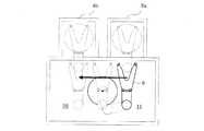
図2は、図1の基板搬送用ロボットが用いられた半導体製造装置(装置7)のレイアウトの一例であり、これの平面図を示している。基板搬送用ロボット1は装置7の略中央に位置し、2つの基板の収納容器8a、8b、又は基板の処理装置9a、9bへ基板把持部6をアクセスさせて基板Wの授受動作を実施する。 FIG. 2 is an example of a layout of a semiconductor manufacturing apparatus (apparatus 7) in which the substrate transfer robot of FIG. 1 is used, and a plan view thereof is shown. The
図3乃至図6は、図2における収納容器8aにアクセスするよう教示された教示位置10と原点位置13の間の基板搬送用ロボット1の基板の搬送経路を示す図である。
アクセス待機位置11は、教示位置10から生成される位置であって、基板搬送用ロボット1が基板Wを収納容器8aに収納或いは搬出開始できる直前の位置に相当し、この位置からまっすぐ収納容器8aに対して基板Wを挿入或いは搬出することができる位置である。アクセス待機位置11は図3乃至図6で同一位置であり、基板搬送用ロボット1の各アーム4、5と基板把持部6がなす姿勢も同一である。なお、ここでは収納容器8aに対するアクセス待機位置11を説明しているが、図2の収納容器8b、及び処理装置9a、9bを含め、基板Wを授受するよう教示された位置に対するアクセス待機位置も存在する。アクセス待機位置は、教示位置に対して把持部や基板が干渉しない位置で、基板Wを授受できる直前の位置である。
原点位置13は、ここでは各アーム4、5と基板把持部6とが最小旋回姿勢をなし、かつ基板把持部6の先端が図の左方向を向いた状態を示す。最小旋回姿勢とは各アーム4、5と基板把持部6とがなす姿勢を旋回中心3を中心に回転させたとき、その平面的に要する旋回半径が最も小さくなる姿勢を指している。3 to 6 are diagrams showing a substrate transfer path of the
The
Here, the
ここで、本発明の搬送経路生成機能について説明する。
図3乃至図6に示すように、収納容器8aへの基板授受位置として教示位置10を教示すると、ロボット1の図示しないコントローラは、上記アクセス待機位置11の生成と同時に、収納容器8aから最小旋回姿勢となるまでの複数の安全な搬送経路も生成する。安全な搬送経路とは、収納容器8aにアクセスする際に、収納容器8aに基板把持部6及び半導体ウェハWが接触しないような搬送経路のことを指す。
すなわち、この時、経由点であるアクセス待機位置11から最小旋回姿勢までの搬送経路として、次の四つの経路をコントローラが生成する。
なお、説明のため、図2に記載しているように、基板把持部6が把持した基板22の中心位置を基板中心23と呼ぶ。また、基板把持部6の回転中心を基板把持部回転中心24と呼ぶ。また、基板把持部回転中心24から基板中心23を結んでできる直線を基板把持部ベクトル25と呼ぶ。Here, the conveyance path | route production | generation function of this invention is demonstrated.
As shown in FIGS. 3 to 6, when the
That is, at this time, the controller generates the following four paths as the transport path from the
For the sake of explanation, as shown in FIG. 2, the center position of the substrate 22 gripped by the
一つ目は、図3で示したように、基板搬送用ロボット1の旋回中心3から基板把持部回転中心24までを結んだ直線のベクトル方向を保ったまま、アクセス待機位置11から最小旋回姿勢(最小旋回A姿勢12と呼ぶ)へと移動する経路である。この場合、基板把持部ベクトル25が旋回中心3を通る向きに基板把持部6を回転させた後、最小旋回姿勢となるよう移動する。
二つ目は、図4で示したように、基板把持部ベクトル25を保ったまま、アクセス待機位置11から最小旋回姿勢(最小旋回B姿勢14と呼ぶ)へと移動する経路である。この場合、基板把持部ベクトル25の方向を保ったまま、アクセス待機位置11から基板把持部ベクトル25が旋回中心3を通り、かつ最小旋回姿勢となる姿勢に同時に移動する。
三つ目は、図5で示したように、アクセス待機位置11の基板把持部回転中心24と、この回転中心が基板搬送用ロボット1を最小旋回姿勢で旋回させた時にできる基板把持部6の回転中心の軌道15に接する最も近い接点17と、を結ぶ直線16上を、基板把持部6の回転中心が移動し、同時に、基板把持部ベクトル25がロボット旋回中心3上を通るように回転することにより、最小旋回姿勢(最小旋回C姿勢18と呼ぶ)へと移動する経路である。
四つ目は、図6で示したように、アクセス待機位置11からまず、基板把持部ベクトル25あるいはその延長線が、最小旋回姿勢で旋回させた時にできる基板把持部6の回転中心の軌道15に接する方向まで、基板把持部6を回転させ(図中X6で示す姿勢)、次に、基板把持部ベクトル25がX6における姿勢での基板把持部ベクトル25に直交し、かつ基板把持部回転中心24が、X6における基板把持部ベクトル25上にある姿勢(図中Y6姿勢)をめざし、基板中心23を移動させる。このとき、基板把持部ベクトル25が軌道15に接する接点P6を中心とし、図中距離a=「X6で示す姿勢における基板把持部回転中心24から基板中心23までの距離」−「X6で示す姿勢における基板把持部回転中心24から前記接点P6までの距離」の2倍を短軸とし、かつ、距離b=「Y6姿勢における基板把持部回転中心24から基板中心23までの距離」を長軸とする楕円上を、基板中心23が移動し、かつ、基板把持部回転中心24がX6姿勢における基板把持部ベクトル25上を移動することにより最小旋回姿勢(最小旋回D姿勢19と呼ぶ)へと移動する経路である。なお、より解りやすくするため、図11にこれらの動きを示す。図11における楕円の太線部が、基板中心23が実際にたどる径路である。First, as shown in FIG. 3, the minimum turning posture from the
As shown in FIG. 4, the second path is a path that moves from the
Third, as shown in FIG. 5, the substrate gripping
Fourth, as shown in FIG. 6, from the
これら四つの経路は、教示位置10と、経由点(アクセス待機位置11)に関する情報は同じであるが、アクセス待機位置11から最小旋回姿勢へと移動する移動経路が異なっている。
以上で説明した複数搬送経路生成は、図2における処理装置9a,9bを教示した場合でも、収納容器8bを教示した場合でも上記と同様に、各教示位置ごとにアクセス待機位置を生成し、このアクセス待機位置から最小旋回姿勢へと移動する複数の搬送経路を生成する。
なお、当然ながら、教示位置によっては複数の搬送経路が生成されない場合もある。
また、実際には、教示位置ごとに対するパラメータによって、各教示位置で複数の搬送経路生成の許可、不許可を指定できるようにしてもよい。これにより、後述する最短経路の選択の際、に選択可能な経路を制限できる。These four routes have the same information regarding the
The multiple transport path generation described above generates an access standby position for each teaching position in the same manner as described above regardless of whether the
Of course, a plurality of transport paths may not be generated depending on the teaching position.
In practice, it may be possible to designate permission / non-permission of the generation of a plurality of transport paths at each teaching position by a parameter for each teaching position. Thereby, the path | route which can be selected at the time of selection of the shortest path | route mentioned later can be restrict | limited.
次に、さらなる搬送経路生成機能について説明する。本発明の搬送経路生成機能では、上記のような最小旋回姿勢となる搬送経路に加えて、以下に説明する場合、さらに別の搬送経路を生成する。
図7は、収納容器8aから別の収納容器8bへの搬送経路を示した図である。図のように収納容器8aと8bは基板搬送用ロボット1の旋回中心3に対して同じ側に並んで配置されており、基板搬送用ロボット1は、これらにアクセスするとき、基板把持部6の回転中心からその先端までのベクトルは互いに平行となる。つまり、これらのアクセス待機位置における基板把持部6の向きは同一となる。このような収納容器8a、8bに対し、コントローラへのプログラミングによって、収納容器8aから8bへロボットが移動するように指定すると、コントローラは、まず当然ながら図3乃至図6で示した最小旋回A、B、C又はD姿勢を経る搬送経路を選択することが可能である。すなわち、例えば図7のような搬送経路である。図7の場合は、図4で示した搬送経路を含むように選択され、最小旋回B姿勢14を経て、収納容器8bまで到達するまでの経路が示されている。なお、図3、図5及び図6で示した搬送経路を含むような経路は、最小旋回A、C又はD姿勢12、18又は19、を経て、その後最小旋回B姿勢14となるように旋回する必要があるので、これらを選択すると搬送時間が多くかかることになり、この場合は図4の搬送経路が選択されている。
しかし、この図7を見ると、アクセス待機位置11から最小旋回B姿勢14を経由せずに目的位置(収納容器8b)のアクセス待機位置20へ直接移動した方が移動距離を短縮できることがわかる。このように、安全な搬送経路が確保できるのであれば、コントローラは、収納容器8aのアクセス待機位置11から目的位置である収納容器8bのアクセス待機位置20へ直接移動する事を許可し、その搬送経路を新たな搬送経路として生成する。この搬送経路を示すのが図8である。図8では図7のように最小旋回B姿勢14を経ることなく、基板把持部6の回転中心からその先端へのベクトル方向を保ったままアクセス待機位置11から目的位置のアクセス待機位置20へ移動する搬送経路を選択している。Next, a further transport route generation function will be described. In the transfer route generation function of the present invention, in addition to the transfer route having the minimum turning posture as described above, another transfer route is generated in the case described below.
FIG. 7 is a diagram showing a transport path from the
However, it can be seen from FIG. 7 that the movement distance can be shortened by moving directly from the
図9は、収納容器8aから処理装置9aへの搬送経路を示した図である。図のように収納容器8aと処理装置9aは基板搬送用ロボット1の旋回中心3に対し対向して配置されている。このような収納容器8a、処理装置9aに対し、コントローラへのプログラミングによって、収納容器8aから処理装置9aへロボットが移動するように指定すると、コントローラは、まず当然ながら図3乃至図6で示した最小旋回A、B、C又はD姿勢を経る搬送経路を選択することが可能である。すなわち、例えば図9のような搬送経路である。図9の場合は、図3で示した搬送経路を含むように選択され、最小旋回A姿勢12を経て、処理装置9aまで到達するまでの経路が示されている。
しかし、この図9を見ると、最小旋回A姿勢12を経由せずに目的位置のアクセス待機位置21へ移動したほうが移動距離を短縮できることがわかる。そこでこの場合、図10のような搬送径路を生成する。図10は、収納容器8aのアクセス待機位置11から最小旋回A姿勢12を経由せずに、目的位置である処理装置9aのアクセス待機位置21へ直接移動する経路を示した図である。図10の経路を説明すると、まず、基板把持部回転中心24が、アクセス待機位置11での基板把持部ベクトル25上を移動しながら、同時に基板把持部6が回転して基板把持部ベクトル25がアクセス待機位置11のときの基板把持部ベクトル25に対して直角となる姿勢であって、基板把持部ベクトル25が旋回中心3を通る姿勢、つまり図中Y10で示す姿勢となる状態をめざす。このとき、基板中心23が、Y10姿勢における基板把持部回転中心24から基板中心23までの距離bの2倍を長軸とし、かつ、アクセス待機位置11とY10姿勢とにおける基板把持部ベクトル25とが交わる点cを中心とし、かつ点cからアクセス待機位置11の状態の基板中心までの距離aの2倍を短軸とする楕円上を移動させる。そして、図中Y10の姿勢から、さらに基板把持部6の回転中心がアクセス待機位置11における基板把持部ベクトル25上を通り、かつ基板中心が上記楕円上を通るように移動させながら、基板把持部6が収納容器8aを向いていた状態から逆を向いた状態である姿勢、つまり処理装置9aのアクセス待機位置21へと移動する。この図10の径路の場合、図9よりも搬送径路が短くなり、搬送時間が短くなることがわかる。
このように、安全な搬送経路が確保できるのであれば、コントローラは、収納容器8aのアクセス待機位置11から目的位置である処理装置9aのアクセス待機位置21へ直接移動する事を許可し、その搬送経路を新たな搬送経路として生成する。FIG. 9 is a diagram showing a transport path from the
However, it can be seen from FIG. 9 that the movement distance can be shortened by moving to the target
In this way, if a safe transfer path can be ensured, the controller permits direct movement from the
次に、本発明の最短経路自動選択機能について説明する。
最短経路自動選択は、ある位置から目的位置への搬送時間が最短となる搬送経路を選択する機能である。教示位置から最小旋回姿勢までの複数の搬送経路は、上記のように収納容器8a、8b及び処理装置9a、9bなどの各教示位置を教示した時点で生成されている。そのため、図3乃至図6に記載されている教示位置10から、ここでは例えば目的位置として原点位置13へ動作する搬送経路において、教示位置10からアクセス待機位置11への移動時間と、アクセス待機位置11から最小旋回A、B、C又はD姿勢12、14、18、19への移動時間と、最小旋回A、B、C又はD姿勢12、14、18、19から原点位置13への移動時間と、を、コントローラは事前に算出することができる。これら各区間の移動時間の合算から、それぞれの搬送経路による目的位置までの搬送時間が算出でき、その搬送時間の比較判断より、最短経路を選択する。図3乃至図6の搬送経路の何れが最短であるかは、その時の基盤搬送用ロボット1の各アーム4、5及び基板把持部6の回転動作速度や各区間における動作量によって異なるために、ロボットの実動作の際に、ある教示位置から目的位置へ移動する都度、移動時間を算出して、比較判断を実施する。
また前記の搬送経路(最小旋回姿勢を経ない図8及び図10で示す搬送経路)も、最短経路自動選択の候補経路に含まれ、比較判断の結果、図8及び図10で示す搬送経路が最短時間の搬送経路であると判断されれば、図8及び図10に示すような搬送経路を動作することになる。Next, the shortest path automatic selection function of the present invention will be described.
The shortest path automatic selection is a function for selecting a transport path that minimizes the transport time from a certain position to a target position. A plurality of conveyance paths from the teaching position to the minimum turning posture are generated when the teaching positions of the
In addition, the above-described transport route (the transport route shown in FIGS. 8 and 10 that does not pass through the minimum turning posture) is also included in the shortest route automatic selection candidate route. As a result of the comparison determination, the transport route shown in FIGS. If it is determined that the transport route is the shortest time, the transport route as shown in FIGS. 8 and 10 is operated.
1.基板搬送用ロボット
2.支柱部
3.旋回中心
4.第1アーム
5.第2アーム
6.基板把持部
7.装置
8.収容容器
9.処理装置
10.教示位置
11.アクセス待機A位置
12.最小旋回A姿勢
13.原点位置
14.最小旋回B姿勢
15.最小旋回姿勢で旋回した時の基板把持部6の回転中心の軌道
16.アクセス待機位置の基板把持部回転中心を通り前記15の軌道に接する接線
17.前記15の軌道と前記16の接線の接点
18.最小旋回C姿勢
19.最小旋回D姿勢
20.アクセス待機B位置
21.アクセス待機C位置
22 基板
23 基板中心
24 基板把持部回転中心
25 基板把持部ベクトル1. 1. substrate transfer
22
Claims (14)
Translated fromJapanese前記基板搬送用ロボットのコントローラは、
前記教示位置が教示されると、前記教示位置の各々に対するアクセス待機位置と、前記アクセス待機位置から前記基板搬送用ロボットの最小旋回姿勢までの複数の経路とを生成して記憶し、
前記経路の1つは、
前記基板把持部の回転中心から前記基板把持部の基板中心へのベクトル方向が前記基板搬送用ロボットの旋回中心を通るように、前記アクセス待機位置から前記基板把持部のみを回転させた後に、当該ベクトル方向を保ったまま前記基板把持部および前記複数のアームを回転させて前記最小旋回姿勢へと移動する経路であること
を特徴とする基板搬送用ロボット。A substrate holding portion for holding a substrate; and a plurality of arms having the substrate holding portion at a tip and capable of rotating in a horizontal plane, and thesubstrate between a plurality of teaching positions previously taughtas asubstrate transfer position In the substrate transfer robot that transfers
The controller of the substrate transfer robot is:
When the frontSymbol teaching indicates positionsRu is taught, the access standby position for each of said taught position,and generates and stores a plurality of routes from the access standby position to the minimum turning posture of the substrate carryingrobot,
One of the routes is
After rotating only the substrate gripping portion from the access standby position so that the vector direction from the rotation center of the substrate gripping portion to the substrate center of the substrate gripping portion passes through the turning center of the substrate transfer robot, A substratetransfer robot, characterized in that the substrateholding robotand the plurality of arms are rotated to move to the minimum turning posture while maintaining a vector direction .
前記複数の教示位置のうち、前記基板把持部の回転中心から前記基板把持部の先端までのベクトルが平行となる第一の教示位置から第二の教示位置まで搬送するよう指定されると、前記第一の教示位置のアクセス待機位置から前記第二の教示位置のアクセス待機位置まで、前記基板が直線搬送可能かどうかを判断し、
前記判断において可能と判断されれば、前記直線搬送の経路を前記第一の教示位置から前記第二の教示位置までの搬送経路としてさらに記憶することを特徴とする基板搬送用ロボット。The robot for transporting a substrate accordingto claim 1,
Among the plurality of teaching positions, when a vector from the first teaching position to which the vector from the rotation center of the substrate gripping portion to the tip of the substrate gripping portion is parallel is designated to be conveyed to the second teaching position, Determining whether the substrate can be linearly transferred from the access standby position of the first teaching position to the access standby position of the second teaching position;
If it is determined that the determination is possible, the substrate transfer robot further stores the linear transfer path as a transfer path from the first teaching position to the second teaching position.
前記複数の教示位置のうち、前記基板把持部の回転中心から前記基板把持部の先端までのベクトルが逆向きとなる第一の教示位置から第二の教示位置まで搬送するよう指定されると、前記第一の教示位置のアクセス待機位置から前記第二の教示位置のアクセス待機位置までの前記基板把持部の回転中心を結ぶ直線を前記基板把持部の回転中心が移動し、同時に、前記基板把持部に把持された前記基板の中心が楕円弧軌道を移動させると前記基板が搬送可能かどうかを判断し、
前記判断において可能と判断されれば、前記楕円弧軌道による搬送の経路を前記第一の教示位置から前記第二の教示位置までの搬送経路としてさらに記憶することを特徴とする基板搬送用ロボット。The robot for transporting a substrate accordingto claim 1,
Among the plurality of teaching positions, when it is designated to transport from the first teaching position to the second teaching position where the vector from the rotation center of the substrate gripping portion to the tip of the substrate gripping portion is opposite, The rotation center of the substrate gripper moves along a straight line connecting the rotation centers of the substrate gripper from the access standby position of the first teaching position to the access standby position of the second teaching position, and at the same time the substrate gripping Determining whether the substrate can be transported when the center of the substrate held by the part moves along an elliptical arc orbit,
If it is determined that the determination is possible, the substrate transfer robot further stores a transfer route by the elliptical arc trajectory as a transfer route from the first teaching position to the second teaching position.
Priority Applications (3)
| Application Number | Priority Date | Filing Date | Title |
|---|---|---|---|
| JP2009031130AJP5504641B2 (en) | 2009-02-13 | 2009-02-13 | Substrate transport robot, substrate transport apparatus including the same, and semiconductor manufacturing apparatus |
| KR1020100012513AKR101500777B1 (en) | 2009-02-13 | 2010-02-10 | Substrate transfer robot and substrate transfer apparatus having the same, and semiconductor manufacturing apparatus |
| US12/704,538US8473096B2 (en) | 2009-02-13 | 2010-02-12 | Substrate transfer robot, substrate transfer device, semiconductor manufacturing apparatus, and method for producing semiconductor |
Applications Claiming Priority (1)
| Application Number | Priority Date | Filing Date | Title |
|---|---|---|---|
| JP2009031130AJP5504641B2 (en) | 2009-02-13 | 2009-02-13 | Substrate transport robot, substrate transport apparatus including the same, and semiconductor manufacturing apparatus |
Publications (2)
| Publication Number | Publication Date |
|---|---|
| JP2010184333A JP2010184333A (en) | 2010-08-26 |
| JP5504641B2true JP5504641B2 (en) | 2014-05-28 |
Family
ID=42560063
Family Applications (1)
| Application Number | Title | Priority Date | Filing Date |
|---|---|---|---|
| JP2009031130AExpired - Fee RelatedJP5504641B2 (en) | 2009-02-13 | 2009-02-13 | Substrate transport robot, substrate transport apparatus including the same, and semiconductor manufacturing apparatus |
Country Status (3)
| Country | Link |
|---|---|
| US (1) | US8473096B2 (en) |
| JP (1) | JP5504641B2 (en) |
| KR (1) | KR101500777B1 (en) |
Families Citing this family (18)
| Publication number | Priority date | Publication date | Assignee | Title |
|---|---|---|---|---|
| AU2007252100B2 (en)* | 2006-05-19 | 2012-12-20 | Scanvaegt International A/S | A method and a system for batching of objects |
| JP5402233B2 (en)* | 2009-05-19 | 2014-01-29 | 株式会社安川電機 | Robot and article transfer system |
| KR101876380B1 (en)* | 2011-07-06 | 2018-07-11 | 삼성전자주식회사 | Manipulator and path generation method thereof |
| JP5756032B2 (en)* | 2012-01-24 | 2015-07-29 | 株式会社安川電機 | Robot system |
| JP5541299B2 (en)* | 2012-01-31 | 2014-07-09 | 株式会社安川電機 | Transport system |
| JP6110636B2 (en)* | 2012-08-09 | 2017-04-05 | 日本電産サンキョー株式会社 | Industrial robot |
| JP6063716B2 (en) | 2012-11-14 | 2017-01-18 | 東京エレクトロン株式会社 | Substrate processing apparatus and substrate transfer method |
| JP5750472B2 (en)* | 2013-05-22 | 2015-07-22 | 株式会社安川電機 | Substrate transport robot, substrate transport system, and method for detecting substrate arrangement state |
| JP6438189B2 (en)* | 2013-10-01 | 2018-12-12 | 川崎重工業株式会社 | Robot and robot control method |
| JP6511806B2 (en)* | 2014-12-25 | 2019-05-15 | シンフォニアテクノロジー株式会社 | Articulated robot and control method of articulated robot |
| JP6804146B2 (en)* | 2016-11-10 | 2020-12-23 | 株式会社ディスコ | Transport equipment, processing equipment and transport method |
| JP6869080B2 (en)* | 2017-03-31 | 2021-05-12 | 株式会社ダイヘン | Robot control device and control program |
| JP6962790B2 (en)* | 2017-11-09 | 2021-11-05 | 日本電産サンキョー株式会社 | Work transfer system and its control method |
| JP6914811B2 (en)* | 2017-11-09 | 2021-08-04 | 日本電産サンキョー株式会社 | Horizontal articulated robot and its origin return method |
| JP7169370B2 (en)* | 2018-12-28 | 2022-11-10 | 川崎重工業株式会社 | ROBOT CONTROL DEVICE, ROBOT SYSTEM AND ROBOT CONTROL METHOD |
| JP7356269B2 (en) | 2019-07-01 | 2023-10-04 | 川崎重工業株式会社 | Robot control device, robot and robot system equipped with the same |
| TWI746014B (en) | 2020-06-16 | 2021-11-11 | 大立鈺科技有限公司 | Wafer access assembly, wafer access device and wafer carrier |
| CN116031184A (en) | 2021-10-25 | 2023-04-28 | 大立钰科技有限公司 | Wafer access assembly, wafer access device and wafer carrier thereof |
Family Cites Families (19)
| Publication number | Priority date | Publication date | Assignee | Title |
|---|---|---|---|---|
| JPH06302667A (en)* | 1993-04-15 | 1994-10-28 | Hitachi Ltd | Chamber system |
| JPH09254064A (en)* | 1996-03-15 | 1997-09-30 | Yaskawa Electric Corp | Teaching point addition method for industrial robots |
| JPH10128687A (en)* | 1996-10-31 | 1998-05-19 | Nippon Telegr & Teleph Corp <Ntt> | Robot control method and device |
| JPH11207671A (en)* | 1998-01-28 | 1999-08-03 | Hitachi Ltd | Industrial robot teaching device |
| JP4238388B2 (en)* | 1998-09-01 | 2009-03-18 | 株式会社ニコン | Microscope with stage |
| JP3971526B2 (en) | 1998-12-02 | 2007-09-05 | 大日本スクリーン製造株式会社 | Substrate loading / unloading apparatus and transfer system |
| US6216058B1 (en)* | 1999-05-28 | 2001-04-10 | Brooks Automation, Inc. | System of trajectory planning for robotic manipulators based on pre-defined time-optimum trajectory shapes |
| WO2003007129A2 (en) | 2001-07-13 | 2003-01-23 | Broks Automation, Inc. | Trajectory planning and motion control strategies for a planar three-degree-of-freedom robotic arm |
| JP2003103481A (en)* | 2001-09-28 | 2003-04-08 | Honda Motor Co Ltd | Method and apparatus for optimizing posture of articulated robot |
| CA2514204C (en)* | 2003-01-31 | 2015-12-15 | Thermo Crs Ltd. | Syntactic inferential motion planning method for robotic systems |
| US7130716B2 (en)* | 2003-04-22 | 2006-10-31 | Berkeley Process Control, Inc. | System of path planning for robotic manipulators based on maximum acceleration and finite jerk constraints |
| JP3999712B2 (en)* | 2003-07-14 | 2007-10-31 | 川崎重工業株式会社 | Articulated robot |
| JP4506255B2 (en)* | 2004-04-19 | 2010-07-21 | 株式会社安川電機 | Wafer position teaching method and robot thereof |
| JP4196911B2 (en)* | 2004-09-06 | 2008-12-17 | セイコーエプソン株式会社 | Orbit determination system and orbit determination method |
| US7651306B2 (en)* | 2004-12-22 | 2010-01-26 | Applied Materials, Inc. | Cartesian robot cluster tool architecture |
| JP4841183B2 (en)* | 2005-06-28 | 2011-12-21 | 東京エレクトロン株式会社 | Substrate processing apparatus, transfer apparatus, and control method of transfer apparatus |
| JP4098338B2 (en)* | 2006-07-20 | 2008-06-11 | 川崎重工業株式会社 | Wafer transfer device and substrate transfer device |
| JP5003890B2 (en)* | 2007-09-06 | 2012-08-15 | 株式会社安川電機 | Substrate transport robot, substrate transport apparatus including the same, and semiconductor manufacturing apparatus |
| JP5339874B2 (en)* | 2008-12-02 | 2013-11-13 | タツモ株式会社 | Robot apparatus and control method thereof |
- 2009
- 2009-02-13JPJP2009031130Apatent/JP5504641B2/ennot_activeExpired - Fee Related
- 2010
- 2010-02-10KRKR1020100012513Apatent/KR101500777B1/ennot_activeExpired - Fee Related
- 2010-02-12USUS12/704,538patent/US8473096B2/ennot_activeExpired - Fee Related
Also Published As
| Publication number | Publication date |
|---|---|
| US20100209225A1 (en) | 2010-08-19 |
| US8473096B2 (en) | 2013-06-25 |
| KR20100092893A (en) | 2010-08-23 |
| KR101500777B1 (en) | 2015-03-09 |
| JP2010184333A (en) | 2010-08-26 |
Similar Documents
| Publication | Publication Date | Title |
|---|---|---|
| JP5504641B2 (en) | Substrate transport robot, substrate transport apparatus including the same, and semiconductor manufacturing apparatus | |
| TWI398335B (en) | Workpiece conveying system | |
| CN109760028A (en) | Horizontal articulated robot and its origin restoration methods | |
| US10836042B2 (en) | Robot system | |
| JP6468159B2 (en) | Transport system and transport method | |
| JP5541299B2 (en) | Transport system | |
| JP2019084651A (en) | Work transfer system and control method thereof | |
| US6435807B1 (en) | Integrated edge gripper | |
| CN101156239A (en) | multi-joint robot | |
| KR100686707B1 (en) | Board Transfer Device | |
| JP2019048349A (en) | Robot system, robot control device, and method of manufacturing workpiece | |
| JP5003890B2 (en) | Substrate transport robot, substrate transport apparatus including the same, and semiconductor manufacturing apparatus | |
| JP4852719B2 (en) | Articulated robot | |
| JP6281554B2 (en) | Teaching jig, robot, teaching system and teaching method | |
| JP7356269B2 (en) | Robot control device, robot and robot system equipped with the same | |
| JP6492271B2 (en) | Transport system and robot | |
| US9099510B2 (en) | Workpiece flipping mechanism for space-constrained environment | |
| CN110962110A (en) | Mechanical arm and automatic conveying device | |
| JP3638775B2 (en) | Redundant robot position determination method for redundant robot | |
| JP2000203421A (en) | Unmanned conveying device and conveying method | |
| US20240383679A1 (en) | Ceiling storage system | |
| US12441009B2 (en) | Vertical articulated robot | |
| US20240342930A1 (en) | Vertical articulated robot | |
| JP7409800B2 (en) | Robot control device, robot, and robot control method | |
| JP5921901B2 (en) | Robot controller |
Legal Events
| Date | Code | Title | Description |
|---|---|---|---|
| A621 | Written request for application examination | Free format text:JAPANESE INTERMEDIATE CODE: A621 Effective date:20111013 | |
| RD02 | Notification of acceptance of power of attorney | Free format text:JAPANESE INTERMEDIATE CODE: A7422 Effective date:20120216 | |
| A977 | Report on retrieval | Free format text:JAPANESE INTERMEDIATE CODE: A971007 Effective date:20121115 | |
| A131 | Notification of reasons for refusal | Free format text:JAPANESE INTERMEDIATE CODE: A131 Effective date:20121120 | |
| A521 | Request for written amendment filed | Free format text:JAPANESE INTERMEDIATE CODE: A523 Effective date:20130115 | |
| A02 | Decision of refusal | Free format text:JAPANESE INTERMEDIATE CODE: A02 Effective date:20131001 | |
| A521 | Request for written amendment filed | Free format text:JAPANESE INTERMEDIATE CODE: A523 Effective date:20131101 | |
| A911 | Transfer to examiner for re-examination before appeal (zenchi) | Free format text:JAPANESE INTERMEDIATE CODE: A911 Effective date:20131202 | |
| TRDD | Decision of grant or rejection written | ||
| A01 | Written decision to grant a patent or to grant a registration (utility model) | Free format text:JAPANESE INTERMEDIATE CODE: A01 Effective date:20140218 | |
| A61 | First payment of annual fees (during grant procedure) | Free format text:JAPANESE INTERMEDIATE CODE: A61 Effective date:20140303 | |
| R150 | Certificate of patent or registration of utility model | Ref document number:5504641 Country of ref document:JP Free format text:JAPANESE INTERMEDIATE CODE: R150 | |
| LAPS | Cancellation because of no payment of annual fees |