JP5503548B2 - Deblocking processing method, deblocking processing apparatus, deblocking processing program, and computer-readable recording medium recording the program - Google Patents
Deblocking processing method, deblocking processing apparatus, deblocking processing program, and computer-readable recording medium recording the programDownload PDFInfo
- Publication number
- JP5503548B2 JP5503548B2JP2010534693AJP2010534693AJP5503548B2JP 5503548 B2JP5503548 B2JP 5503548B2JP 2010534693 AJP2010534693 AJP 2010534693AJP 2010534693 AJP2010534693 AJP 2010534693AJP 5503548 B2JP5503548 B2JP 5503548B2
- Authority
- JP
- Japan
- Prior art keywords
- block
- edge
- deblocking
- filter
- processing
- Prior art date
- Legal status (The legal status is an assumption and is not a legal conclusion. Google has not performed a legal analysis and makes no representation as to the accuracy of the status listed.)
- Active
Links
Images


Classifications
- H—ELECTRICITY
- H04—ELECTRIC COMMUNICATION TECHNIQUE
- H04N—PICTORIAL COMMUNICATION, e.g. TELEVISION
- H04N19/00—Methods or arrangements for coding, decoding, compressing or decompressing digital video signals
- H04N19/10—Methods or arrangements for coding, decoding, compressing or decompressing digital video signals using adaptive coding
- H04N19/102—Methods or arrangements for coding, decoding, compressing or decompressing digital video signals using adaptive coding characterised by the element, parameter or selection affected or controlled by the adaptive coding
- H04N19/117—Filters, e.g. for pre-processing or post-processing
- H—ELECTRICITY
- H04—ELECTRIC COMMUNICATION TECHNIQUE
- H04N—PICTORIAL COMMUNICATION, e.g. TELEVISION
- H04N19/00—Methods or arrangements for coding, decoding, compressing or decompressing digital video signals
- H04N19/10—Methods or arrangements for coding, decoding, compressing or decompressing digital video signals using adaptive coding
- H04N19/134—Methods or arrangements for coding, decoding, compressing or decompressing digital video signals using adaptive coding characterised by the element, parameter or criterion affecting or controlling the adaptive coding
- H04N19/136—Incoming video signal characteristics or properties
- H04N19/14—Coding unit complexity, e.g. amount of activity or edge presence estimation
- H—ELECTRICITY
- H04—ELECTRIC COMMUNICATION TECHNIQUE
- H04N—PICTORIAL COMMUNICATION, e.g. TELEVISION
- H04N19/00—Methods or arrangements for coding, decoding, compressing or decompressing digital video signals
- H04N19/10—Methods or arrangements for coding, decoding, compressing or decompressing digital video signals using adaptive coding
- H04N19/134—Methods or arrangements for coding, decoding, compressing or decompressing digital video signals using adaptive coding characterised by the element, parameter or criterion affecting or controlling the adaptive coding
- H04N19/157—Assigned coding mode, i.e. the coding mode being predefined or preselected to be further used for selection of another element or parameter
- H—ELECTRICITY
- H04—ELECTRIC COMMUNICATION TECHNIQUE
- H04N—PICTORIAL COMMUNICATION, e.g. TELEVISION
- H04N19/00—Methods or arrangements for coding, decoding, compressing or decompressing digital video signals
- H04N19/10—Methods or arrangements for coding, decoding, compressing or decompressing digital video signals using adaptive coding
- H04N19/169—Methods or arrangements for coding, decoding, compressing or decompressing digital video signals using adaptive coding characterised by the coding unit, i.e. the structural portion or semantic portion of the video signal being the object or the subject of the adaptive coding
- H04N19/17—Methods or arrangements for coding, decoding, compressing or decompressing digital video signals using adaptive coding characterised by the coding unit, i.e. the structural portion or semantic portion of the video signal being the object or the subject of the adaptive coding the unit being an image region, e.g. an object
- H04N19/176—Methods or arrangements for coding, decoding, compressing or decompressing digital video signals using adaptive coding characterised by the coding unit, i.e. the structural portion or semantic portion of the video signal being the object or the subject of the adaptive coding the unit being an image region, e.g. an object the region being a block, e.g. a macroblock
- H—ELECTRICITY
- H04—ELECTRIC COMMUNICATION TECHNIQUE
- H04N—PICTORIAL COMMUNICATION, e.g. TELEVISION
- H04N19/00—Methods or arrangements for coding, decoding, compressing or decompressing digital video signals
- H04N19/10—Methods or arrangements for coding, decoding, compressing or decompressing digital video signals using adaptive coding
- H04N19/169—Methods or arrangements for coding, decoding, compressing or decompressing digital video signals using adaptive coding characterised by the coding unit, i.e. the structural portion or semantic portion of the video signal being the object or the subject of the adaptive coding
- H04N19/182—Methods or arrangements for coding, decoding, compressing or decompressing digital video signals using adaptive coding characterised by the coding unit, i.e. the structural portion or semantic portion of the video signal being the object or the subject of the adaptive coding the unit being a pixel
- H—ELECTRICITY
- H04—ELECTRIC COMMUNICATION TECHNIQUE
- H04N—PICTORIAL COMMUNICATION, e.g. TELEVISION
- H04N19/00—Methods or arrangements for coding, decoding, compressing or decompressing digital video signals
- H04N19/80—Details of filtering operations specially adapted for video compression, e.g. for pixel interpolation
- H04N19/82—Details of filtering operations specially adapted for video compression, e.g. for pixel interpolation involving filtering within a prediction loop
- H—ELECTRICITY
- H04—ELECTRIC COMMUNICATION TECHNIQUE
- H04N—PICTORIAL COMMUNICATION, e.g. TELEVISION
- H04N19/00—Methods or arrangements for coding, decoding, compressing or decompressing digital video signals
- H04N19/85—Methods or arrangements for coding, decoding, compressing or decompressing digital video signals using pre-processing or post-processing specially adapted for video compression
- H04N19/86—Methods or arrangements for coding, decoding, compressing or decompressing digital video signals using pre-processing or post-processing specially adapted for video compression involving reduction of coding artifacts, e.g. of blockiness
Landscapes
- Engineering & Computer Science (AREA)
- Multimedia (AREA)
- Signal Processing (AREA)
- Compression Or Coding Systems Of Tv Signals (AREA)
Description
Translated fromJapanese 本発明は、ブロックベースの予測符号化を実装する映像符号化装置や映像復号装置で用いられるデブロッキング処理方法およびその装置と、そのデブロッキング処理方法の実現に用いられるデブロッキング処理プログラムおよびそのプログラムを記録したコンピュータ読み取り可能な記録媒体とに関する。
本願は、2008年10月22日に、日本に出願された特願2008−271496号に基づいて優先権を主張し、その内容をここに援用する。The present invention relates to a deblocking processing method and apparatus used in a video encoding apparatus and video decoding apparatus that implement block-based predictive encoding, a deblocking processing program used for realizing the deblocking processing method, and the program And a computer-readable recording medium on which is recorded.
This application claims priority on October 22, 2008 based on Japanese Patent Application No. 2008-271696 for which it applied to Japan, and uses the content for it here.
映像符号化において、異なる画面間で予測を実行する画面間予測符号化(動き補償)では、参照する画像は復号された画像を用いるようにしている。このため、低ビットレートで符号化する場合、ブロック歪みが発生して復号された画像は劣化し、その劣化した画像を参照するため、画質劣化が伝播する問題があった。 In video encoding, in inter-screen predictive encoding (motion compensation) in which prediction is performed between different screens, a decoded image is used as a reference image. For this reason, when encoding at a low bit rate, there is a problem in that image quality deterioration propagates because the decoded image deteriorates due to block distortion and the deteriorated image is referred to.
そこで、ブロック歪みを低減させるループ内フィルタが提案されており、映像符号化標準に導入されている。また、現在、国際標準化会合ISO MPEG(Moving Picture Experts Group)やITU−T(国際電気通信連合 電気通信標準化部門) VCEG(Video Coding Experts Group)でもループ内フィルタに限らず、プレフィルタやポストフィルタも含めてフィルタ関連の提案は数多くされ、活発に議論されている。プレフィルタやポストフィルタと異なり、ループ内フィルタを使用することで、フィルタがかかる対象画像の画質が改善されるだけでなく、その画像を参照する後続のフレームへの影響も改善され、映像全体の画質向上(符号化効率改善)が可能になる。このため、ループ内フィルタの改善は非常に期待される領域である。 Therefore, an in-loop filter for reducing block distortion has been proposed and introduced into a video coding standard. Currently, ISO MPEG (Moving Picture Experts Group) and ITU-T (International Telecommunication Union Telecommunication Standardization Sector) VCEG (Video Coding Experts Group) are not limited to in-loop filters, pre-filters and post-filters. Many proposals related to filters, including those, have been actively discussed. Unlike pre-filters and post-filters, the use of in-loop filters not only improves the quality of the filtered target image, but also improves the effect on subsequent frames that reference the image, so Image quality improvement (encoding efficiency improvement) becomes possible. For this reason, the improvement of the in-loop filter is a highly expected area.
映像情報を符号化する場合、現状のMPEG−1やMPEG−2やMPEG−4やH.261やH.262やH.264などの映像符号化標準においては、画像をM×N(MおよびNは2の倍数、例えば4,8,16)のブロックに分割して符号化を行う。分割後、画面内や画面間で、処理対象ブロックと参照ブロック(復号したブロック)との差分を取り、その残差信号を直交変換し、量子化をしてエントロピー符号化を施し、バイナリデータとして出力する。 When encoding video information, the current MPEG-1, MPEG-2, MPEG-4, H.264, or H.264 format is used. 261 and H.264. 262 or H.264. In a video encoding standard such as H.264, an image is divided into M × N blocks (M and N are multiples of 2, for example, 4, 8, 16) and encoded. After the division, the difference between the block to be processed and the reference block (decoded block) is taken within the screen or between the screens, the residual signal is orthogonally transformed, quantized and entropy-coded, as binary data Output.
人間の視覚特性が高周波に鈍感であることを利用して、量子化をする際に、画像の高周波成分は削除される。このときブロック単位で高周波成分が落とされるため、復号された画像では、ブロックの境界が目立ち、ブロック状のノイズが乗ることになる。特に映像に割り当てられる符号量が低い状況(すなわち、低ビットレート)では、ブロックノイズが顕著に視認される。 Taking advantage of the fact that human visual characteristics are insensitive to high frequencies, the high frequency components of the image are deleted when quantization is performed. At this time, since the high frequency component is dropped in units of blocks, the block boundaries are conspicuous in the decoded image, and block-like noise is added. In particular, in a situation where the code amount allocated to the video is low (that is, a low bit rate), block noise is noticeable visually.
動き補償型画面間予測符号化においては、過去もしくは未来にある参照フレームと処理対象フレームとの残差信号および動きベクトル(移動量)を送信することで、時間方向の冗長性を削減する。この動き補償型画面間予測符号化においては、参照先の画像にブロック状のノイズが含まれていて劣化している場合、参照フレームと処理対象フレームとの間の差分を取ると、その残差信号は増え、符号化効率の低下を招く結果となる。 In motion-compensated inter-frame predictive coding, temporal direction redundancy is reduced by transmitting a residual signal and a motion vector (movement amount) between a reference frame and a processing target frame in the past or the future. In this motion-compensated inter-screen predictive coding, when the reference image contains block noise and deteriorates, the difference between the reference frame and the frame to be processed is taken as the residual. The number of signals increases, resulting in a decrease in coding efficiency.
そこで、H.264/AVCでは、参照フレーム、すなわち復号画像をフレームメモリに格納する際に、符号化時に発生するブロックノイズを減少させるフィルタを使用する。本フィルタをデブロッキングフィルタと呼ぶ。 Therefore, H.H. In H.264 / AVC, when a reference frame, that is, a decoded image is stored in a frame memory, a filter that reduces block noise generated during encoding is used. This filter is called a deblocking filter.
なお、以上に記載した点については、下記に示す非特許文献1のpp. 140-144およびp. 269に記載されている。 The points described above are described in pp. 140-144 and p. 269 of Non-Patent
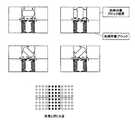
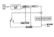
図24Aに、符号化の工程におけるデブロッキングフィルタの位置を示し、図24Bに、復号の工程におけるデブロッキングフィルタの位置を示す。 FIG. 24A shows the position of the deblocking filter in the encoding step, and FIG. 24B shows the position of the deblocking filter in the decoding step.
デブロッキングフィルタの処理は、1つのマクロブロック(以下、MBと略記する)を分割して得られる16個のブロック(4×4)の各ブロック境界に対して施される。また、MB境界の場合、隣接MBが存在すれば、フィルタに必要な画素が得られるため、処理を同様に施す。 The deblocking filter process is performed on each block boundary of 16 blocks (4 × 4) obtained by dividing one macroblock (hereinafter abbreviated as MB). In the case of an MB boundary, if there is an adjacent MB, a pixel necessary for the filter can be obtained, and thus the same processing is performed.
図25Aおよび図25Bに、具体的な処理箇所を示す。ここで、図25Aは垂直方向のブロック境界に関するフィルタの位置を示す。また、図25Bは水平方向のブロック境界に関するフィルタ位置を示す。ただし、処理対象MBが輝度信号の8×8ブロックで処理された場合には、基本的に実線部分のみ処理を施し、輝度信号そして色差信号の4×4ブロックで処理された場合には、実線と破線部分の両方を処理する。 FIG. 25A and FIG. 25B show specific processing locations. Here, FIG. 25A shows the position of the filter with respect to the block boundary in the vertical direction. FIG. 25B shows the filter position with respect to the block boundary in the horizontal direction. However, when the processing target MB is processed with 8 × 8 blocks of luminance signals, only the solid line portion is basically processed, and when processed with 4 × 4 blocks of luminance signals and color difference signals, solid lines are processed. And both broken lines.
なお、以上に記載した点については、下記に示す非特許文献2のpp. 182-193に記載されている。 The points described above are described in pp. 182-193 of
画像の特性によって、ブロック歪みが発生し易い箇所と発生しにくい箇所があるため、デブロッキングフィルタの処理は適応的に施される。具体的には、
・境界強度(Bs値:Boundary Strength)
・境界間画素の差分の絶対値
の条件に従って、処理が変化する。下記の表1に、境界強度の定義を示す。Depending on the characteristics of the image, there are locations where block distortion is likely to occur and locations where block distortion is unlikely to occur, so the deblocking filter processing is adaptively performed. In particular,
・ Boundary strength (Bs value: Boundary Strength)
The processing changes according to the condition of the absolute value of the difference between the pixels between the boundaries. Table 1 below shows the definition of boundary strength.

また、図25Aおよび図25Bに示されるように、1つのブロックの画素値をpm(0≦m<4:ブロック境界に近いほど添字は小さい)、もう一方のブロックの画素値をqn(0≦n<4:ブロック境界に近いほど添字は小さい)とする場合、
1.Bs>0
2.|p0−q0|<α && |p1−p0|<β && |q1−q0|<β
という2つの条件を満たす場合に、デブロッキングフィルタは動作する。Further, as shown in FIGS. 25A and 25B, 1 single pixel values pm of the block (0 ≦ m <4: small index closer to the block boundary), the pixel values of the other blocks qn ( 0 ≦ n <4: the closer to the block boundary, the smaller the subscript)
1. Bs> 0
2. | p0 −q0 | <α && | p1 −p0 | <β && | q1 −q0 | <β
The deblocking filter operates when the two conditions are satisfied.
ここで、αおよびβは符号化時に定める量子化パラメータ(QP:Quantization Parameter)に依存して、一意に定まる。また、ユーザー側もスライスヘッダに含まれる2つのパラメータslice_alpha_c0_offset_div2およびslice_beta_offset_div2のフラグを利用することで、αおよびβを調整することが可能となっている。 Here, α and β are uniquely determined depending on a quantization parameter (QP) defined at the time of encoding. The user can also adjust α and β by using the flags of two parameters slice_alpha_c0_offset_div2 and slice_beta_offset_div2 included in the slice header.
さらに、上記の2つのパラメータ以外に、ピクチャパラメータセット(ヘッダ部分)にて、deblocking_filter_control_present_flagおよびdisable_deblocking_filter_idc の2つのパラメータにより、
1.ブロック境界、およびMB境界にデブロッキングフィルタを施す
2.MB境界のみにデブロッキングフィルタを施す
3.デブロッキングフィルタを施さない
というように、3種類のレベルに分けて、デブロッキングフィルタの制御が可能となっている。Furthermore, in addition to the above two parameters, in the picture parameter set (header part), by two parameters deblocking_filter_control_present_flag and disable_deblocking_filter_idc,
1. 1. Apply deblocking filter to block boundary and
なお、デブロッキングフィルタとは関係しないが、画面内予測の性能を改善する様々な手法が提案されている。本発明者も、画像のテクスチャに合わせて傾斜を付けて予測することで画面内予測の性能を改善する手法を提案している(非特許文献3参照)。 Although not related to the deblocking filter, various methods for improving the performance of intra prediction are proposed. The present inventor has also proposed a method for improving the performance of in-screen prediction by making an inclination in accordance with the texture of an image (see Non-Patent Document 3).
従来のデブロッキングフィルタでは、ブロック境界に対して、常に垂直方向(90°)に画素をとり、(i)境界強度と、(ii)選択された画素の差分の絶対値という2つの条件によって、フィルタ処理を適応的に施していた。 In the conventional deblocking filter, pixels are always taken in the vertical direction (90 °) with respect to the block boundary, and (i) the boundary strength and (ii) the absolute value of the difference between the selected pixels, Filter processing was applied adaptively.
しかしながら、従来技術では垂直方向のみの画素処理になるため、仮に符号化対象画像が固有の斜め方向のテクスチャ(例えば、斜めの模様や線)を有する場合、そのテクスチャをぼかしてしまう可能性があった。 However, since the conventional technique performs pixel processing only in the vertical direction, if the encoding target image has a unique oblique texture (for example, an oblique pattern or line), the texture may be blurred. It was.
すなわち、従来のデブロッキングフィルタは適応的に処理を施すものの、元来画像に含まれるテクスチャの方向を考慮して処理するという機構は有していない。このため、従来技術に従っていると、本来残すべきテクスチャに対してもフィルタを施してしまうことから、斜めのテクスチャ成分が滑らかになり、主観画質が劣化する可能性があった。 That is, although the conventional deblocking filter performs processing adaptively, it does not have a mechanism for processing in consideration of the direction of the texture originally included in the image. For this reason, according to the prior art, since the filter should be applied to the texture that should remain, the oblique texture component may become smooth and the subjective image quality may deteriorate.
本発明はかかる事情に鑑みてなされたものであって、画像に残すべき斜め方向のテクスチャを保存し、かつブロックノイズを効率的に削減可能とする新たなデブロッキング処理技術の提供を目的とするものである。また、これにより、単一画像の主観画質向上だけでなく、画質が向上した画像を参照することにより画面間予測符号化の性能も向上させることで、映像情報全体の符号化効率向上を実現可能とすることを目的とするものである。 The present invention has been made in view of such circumstances, and it is an object of the present invention to provide a new deblocking processing technique that preserves an oblique texture to be left in an image and can efficiently reduce block noise. Is. In addition to improving the subjective image quality of a single image, this also improves the coding efficiency of the entire video information by improving the performance of inter-picture predictive coding by referring to the image with improved image quality. It is intended to be.
この目的を達成するために、本発明のデブロッキング処理方法は、ブロックベースの予測符号化を行う映像符号化方式や、前記映像符号化方式により符号化された映像を復号する映像復号方式で発生するブロック歪みを低減させるためのデブロッキング処理装置が実行するデブロッキング処理方法であって、前記デブロッキング処理装置の検出手段が、各ブロックについて、各ブロックの画素値の変化方向を示すエッジがどちらの方向への画素値変化を示しているのかを検出する検出ステップと、前記デブロッキング処理装置の決定手段が、デブロッキングの対象となるブロック境界を持つ処理対象ブロックおよび前記処理対象ブロックに接するブロックについて検出した前記エッジの方向に基づいて、前記ブロック境界に対して施すデブロッキングフィルタの施す方向を決定する決定ステップと、前記デブロッキング処理装置のフィルタ実行手段が、前記決定した方向に従って、前記ブロック境界に対して前記デブロッキングフィルタを施すフィルタ実行ステップとを有する。In order to achieve this object, the deblocking processing method of the present invention is generated by a video encoding system that performs block-based predictive encoding and a video decoding system that decodes video encoded by the video encoding system. A deblocking processing methodexecuted by a deblocking processing device for reducing block distortion, in whichthe detection means of the deblocking processing device has an edge indicating a change direction of a pixel value of each block for each block. A detection step for detecting whether or not a pixel value change in the direction is indicated, and a processing block having a block boundary to be deblocked by thedetermining means of the deblocking processing device and a block in contact with the processing target block Based on the edge direction detected for the block boundary. A determination step of determining the direction of applying King filter,filter execution means of the deblocking apparatus inaccordance with the direction in which the determined, and a filter execution step of applying the deblocking filter to the block boundary.
本発明のデブロッキング処理方法において、前記検出ステップでは、前記検出手段が、各ブロックについて、各ブロックの画素値変化の水平方向の成分を検出するとともに、各ブロックの画素値変化の垂直方向の成分を検出して、検出した前記水平方向の成分および前記垂直方向の成分に基づいて、前記エッジの方向を検出するようにしても良い。In the deblocking processing method of the present invention, in the detection step, thedetection means detects, for each block, a horizontal component of a pixel value change of each block, and a vertical component of a pixel value change of each block. And the edge direction may be detected based on the detected horizontal component and the detected vertical component.
本発明のデブロッキング処理方法において、前記検出ステップでは、前記検出手段が、各ブロックについて、各ブロックを画面内符号化した場合に用いられる予測モードの情報を取得して、取得した前記予測モードの情報に基づいて、前記エッジの方向を検出するようにしても良い。In the deblocking processing method of the present invention, in the detection step, thedetection unit acquires, for each block, information on a prediction mode used when each block is intra-coded, and the acquired prediction mode The direction of the edge may be detected based on the information.
本発明のデブロッキング処理方法において、前記デブロッキング処理装置の算出手段が、各ブロックについて、検出した前記水平方向の成分および前記垂直方向の成分に基づいて、前記エッジの強度を算出する算出ステップを備え、前記決定ステップでは、前記決定手段が、前記処理対象ブロックについて算出した前記エッジの強度と所定の閾値とを比較し、前記エッジの強度が前記所定の閾値以下である場合には、前記エッジの方向に基づいて決定した前記デブロッキングフィルタの施す方向を前記ブロック境界に直交する方向に変更するようにしても良い。In the deblocking processing method of the present invention,the calculating step of the deblocking processing device includes a calculating step of calculating the intensity of the edge based on the detected horizontal component and vertical component for each block. In the determining step, thedetermining means compares the edge strength calculated for the processing target block with a predetermined threshold value, and if the edge strength is equal to or lower than the predetermined threshold value, the edge The direction on which the deblocking filter is determined based on the direction may be changed to a direction orthogonal to the block boundary.
本発明のデブロッキング処理方法において、前記決定ステップでは、前記決定手段が、前記処理対象ブロックについての前記予測モードの情報が画素平均値を予測信号とする予測モードであることを示している場合には、前記エッジの方向に基づいて決定した前記デブロッキングフィルタの施す方向を前記ブロック境界に直交する方向に変更するようにしても良い。In the deblocking processing method of the present invention, in the determination step, thedetermination means indicates that the prediction mode information for the processing target block is a prediction mode using a pixel average value as a prediction signal. The direction of the deblocking filter determined based on the direction of the edge may be changed to a direction orthogonal to the block boundary.
本発明のデブロッキング処理方法において、前記決定ステップでは、前記決定手段が、前記処理対象ブロックおよび前記処理対象ブロックに接する前記ブロックについて検出した前記エッジの方向をキーにして、前記処理対象ブロックおよび前記処理対象ブロックに接する前記ブロックの前記エッジの方向と前記デブロッキングフィルタの施す方向との対応関係について記述する情報を記憶する記憶手段の記憶データを参照することで、前記デブロッキングフィルタの施す方向を決定するようにしても良い。In the deblocking processing method of the present invention, in the determination step, thedetermination means uses the detected edge direction for the block to be processed and the block in contact with the block to be processed as a key, and the block to be processed and the block By referring to stored data of storage means for storing information describing the correspondence relationship between the direction of the edge of the block in contact with the processing target block and the direction to which the deblocking filter is applied, the direction to which the deblocking filter is applied is determined. It may be determined.
本発明のデブロッキング処理装置は、ブロックベースの予測符号化を行う映像符号化方式や、前記映像符号化方式により符号化された映像を復号する映像復号方式で発生するブロック歪みを低減させるためのデブロッキング処理装置であって、各ブロックについて、各ブロックの画素値の変化方向を示すエッジがどちらの方向への画素値変化を示しているのかを検出する検出手段と、デブロッキングの対象となるブロック境界を持つ処理対象ブロックおよび前記処理対象ブロックに接するブロックについて検出した前記エッジの方向に基づいて、前記ブロック境界に対して施すデブロッキングフィルタの施す方向を決定する決定手段と、前記決定した方向に従って、前記ブロック境界に対して前記デブロッキングフィルタを施すフィルタ実行手段とを有する。 The deblocking processing apparatus according to the present invention reduces block distortion that occurs in a video encoding scheme that performs block-based predictive encoding and a video decoding scheme that decodes video encoded by the video encoding scheme. A deblocking processing device, for each block, detection means for detecting in which direction an edge indicating a change direction of a pixel value of each block indicates a change in the pixel value, and is a deblocking target Determining means for determining a direction to apply a deblocking filter to the block boundary based on the direction of the edge detected for the processing target block having a block boundary and a block in contact with the processing target block; and the determined direction Filter execution to apply the deblocking filter to the block boundary according to And a stage.
本発明のデブロッキング処理装置において、前記処理対象ブロックおよび前記処理対象ブロックに接する前記ブロックの前記エッジの方向と前記デブロッキングフィルタの施す方向との対応関係について記述する情報を記憶する記憶手段を備え、前記決定手段は、前記処理対象ブロックおよび前記処理対象ブロックに接する前記ブロックについて検出した前記エッジの方向をキーにして、前記記憶手段の記憶データを参照することで、前記デブロッキングフィルタの施す方向を決定するようにしても良い。 The deblocking processing apparatus of the present invention comprises storage means for storing information describing a correspondence relationship between the direction of the edge of the block to be processed and the block in contact with the block to be processed and the direction to which the deblocking filter is applied. The determining means refers to the data stored in the storage means by using the direction of the edge detected for the processing target block and the block in contact with the processing target block as a key, so that the deblocking filter is applied. May be determined.
本発明のデブロッキング処理プログラムは、上記デブロッキング処理方法の各ステップをコンピュータに実行させるためのデブロッキング処理プログラムである。The deblocking processing program of this invention is a deblocking processing program for making a computer performeach step of the said deblocking processing method.
本発明のコンピュータ読み取り可能な記録媒体は、上記デブロッキング処理方法の各ステップをコンピュータに実行させるためのデブロッキング処理プログラムを記録したコンピュータ読み取り可能な記録媒体である。The computer-readable recording medium of the present invention is a computer-readable recording medium recording a deblocking processing program for causing a computer to executeeach step of the deblocking processing method.
以上説明したように、本発明によれば、従来のデブロッキングフィルタでは斜め方向のエッジが保存できず、画質の劣化を招くと考えられる斜め方向のエッジを多く含む画像に対して、保存すべき斜め方向のテクスチャも保存しつつ、ブロック境界に存在するブロックノイズを削減することができるようになる。したがって、主観画質の向上を実現できるようになる。 As described above, according to the present invention, the conventional deblocking filter cannot store the edge in the oblique direction, and should be preserved for an image including a large number of the edge in the oblique direction that is considered to cause deterioration in image quality. Block noise existing at the block boundary can be reduced while preserving the texture in the diagonal direction. Therefore, improvement in subjective image quality can be realized.
そして、本発明によれば、デコードされる画像が高画質化されることから、この画像を参照する画面間予測符号化にて、残差信号を低下させることができ、その結果として符号化効率の向上を実現できるようになる。 According to the present invention, since the image to be decoded has a high image quality, the residual signal can be reduced in the inter-screen predictive coding referring to this image, and as a result, the coding efficiency is improved. Can be improved.
まず、本発明の実施形態を説明するのに先立ち、本発明が適用されるデブロッキング処理方法、デブロッキング処理装置、デブロッキング処理プログラムの基本原理について説明する。本発明が適用されるデブロッキング処理方法、デブロッキング処理装置、デブロッキング処理プログラムでは、ブロック境界に対する垂直方向のみだけでなく、画像の有するテクスチャの向きに応じてフィルタの方向を適応的に変化させて画素変換処理を施すようにしている。これにより、画像固有のテクスチャを保存しつつ、ブロックノイズを効率的に削減することが可能となり、主観画質を向上させるデブロッキングフィルタを実現することができるようになる。 First, prior to describing an embodiment of the present invention, a basic principle of a deblocking processing method, a deblocking processing apparatus, and a deblocking processing program to which the present invention is applied will be described. In the deblocking processing method, the deblocking processing apparatus, and the deblocking processing program to which the present invention is applied, not only the vertical direction with respect to the block boundary but also the direction of the filter is adaptively changed according to the texture direction of the image. Thus, pixel conversion processing is performed. As a result, it is possible to efficiently reduce block noise while preserving image-specific texture, and to realize a deblocking filter that improves subjective image quality.
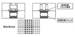
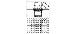
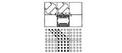
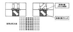
図1の(a)部分に示すように、符号化対象ブロックが斜め方向にテクスチャを含む場合を想定する。 As illustrated in part (a) of FIG. 1, a case is assumed where the encoding target block includes a texture in an oblique direction.
この場合、図1の(b)部分のように、従来のデブロッキングフィルタを施すと、ブロック境界のブロックノイズは削減できるが、斜めのテクスチャも状況に応じて平滑化するため、テクスチャに影響を与える可能性がある。 In this case, if the conventional deblocking filter is applied as shown in part (b) of FIG. 1, the block noise at the block boundary can be reduced, but since the diagonal texture is also smoothed according to the situation, the texture is affected. There is a possibility to give.
そこで、図1の(c)部分のように、テクスチャの向きに応じて斜め方向にフィルタ処理を行うことで、テクスチャを残しつつ、ブロックノイズを削減させる。これにより、主観画質の向上を実現できるとともに、処理画像を参照する場合の残差信号の削減を実現でき、符号化効率の向上も実現できるようになる。 Therefore, as shown in FIG. 1 (c), the block noise is reduced while leaving the texture by performing the filtering process in an oblique direction according to the direction of the texture. As a result, the subjective image quality can be improved, the residual signal when the processed image is referred to can be reduced, and the encoding efficiency can be improved.
次に、このことを実現するデブロッキング処理装置の構成について説明する。 Next, the structure of the deblocking processing apparatus which implement | achieves this is demonstrated.
このデブロッキング処理装置は、ブロックベースの予測符号化を行う映像符号化方式や、前記映像符号化方式により符号化された映像を復号する映像復号方式で発生するブロック歪みを低減させることを実現するために、(1)各ブロックについて、各ブロックの画素値の変化方向を示すエッジがどちらの方向への画素値変化を示しているのかを検出する検出手段と、(2)デブロッキングの対象となるブロック境界を持つ処理対象ブロックおよび前記処理対象ブロックに接するブロック(上下左右斜め方向で接するブロック)について検出した前記エッジの方向に基づいて、前記ブロック境界に対して施すデブロッキングフィルタの施す方向を決定する決定手段と、(3)前記決定手段の決定した方向に従って、前記デブロッキングの対象となる前記ブロック境界に対して前記デブロッキングフィルタを施すフィルタ実行手段とを備える。 This deblocking processing device realizes reduction of block distortion that occurs in a video encoding system that performs block-based predictive encoding and a video decoding system that decodes video encoded by the video encoding system. For this purpose, (1) for each block, detection means for detecting in which direction an edge indicating the change direction of the pixel value of each block indicates a change in the pixel value, and (2) a deblocking target Based on the direction of the edge detected for a processing target block having a block boundary and a block in contact with the processing target block (a block touching in an up / down / left / right diagonal direction), a direction to apply a deblocking filter to the block boundary is determined. (3) the deblocking target according to the direction determined by the determining means; To the block boundary corresponding and a filter execution means for applying the deblocking filter.
さらに、前記処理対象ブロックおよび前記処理対象ブロックに接する前記ブロックの前記エッジの方向と前記デブロッキングフィルタの施す方向との対応関係について記述する情報を記憶する記憶手段を備えることがある。この場合には、前記決定手段は、前記処理対象ブロックおよび前記処理対象ブロックに接する前記ブロックについて検出された前記エッジの方向をキーにして、この記憶手段の記憶データを参照することで、前記デブロッキングフィルタの施す方向を決定することになる。 The information processing apparatus may further include a storage unit that stores information describing a correspondence relationship between a direction of the edge of the block to be processed and the block in contact with the block to be processed and a direction to which the deblocking filter is applied. In this case, the determination means refers to the data stored in the storage means by using the edge direction detected for the processing target block and the block in contact with the processing target block as a key. The direction in which the blocking filter is applied is determined.
この構成を採るときに、検出手段は、各ブロックについて、各ブロックの画素値の水平方向の成分を検出するとともに、各ブロックの画素値変化の垂直方向の成分を検出して、検出した前記水平方向の成分および前記垂直方向の成分に基づいて、前記エッジの方向を検出することがある。 When adopting this configuration, the detecting means detects the horizontal component of the pixel value of each block and detects the vertical component of the pixel value change of each block for each block, and detects the detected horizontal The edge direction may be detected based on a direction component and the vertical direction component.
この場合に、各ブロックについて、前記検出手段の検出した前記水平方向の成分および前記垂直方向の成分に基づいて、前記エッジの強度を算出する算出手段を備えることがある。この算出手段を備える場合において、前記決定手段は、前記算出手段が前記処理対象ブロックについて算出した前記エッジの強度と所定の閾値とを比較し、前記エッジの強度が前記所定の閾値以下である場合には、前記検出手段の検出した前記エッジの方向に基づいて決定した前記デブロッキングフィルタの施す方向を前記デブロッキングの対象となる前記ブロック境界に直交する方向に変更することがある。 In this case, for each block, there may be provided calculation means for calculating the strength of the edge based on the horizontal component and the vertical component detected by the detection means. In the case of including this calculation means, the determination means compares the edge strength calculated by the calculation means for the processing target block with a predetermined threshold value, and the edge strength is equal to or less than the predetermined threshold value. In some cases, the direction of the deblocking filter determined based on the edge direction detected by the detection means is changed to a direction orthogonal to the block boundary to be deblocked.
また、この構成を採るときに、前記検出手段は、各ブロックについて、各ブロックを画面内符号化した場合に用いられる予測モードの情報を取得して、取得した前記予測モードの情報に基づいて、エッジの方向を検出することがある。 Further, when adopting this configuration, the detection means acquires information on the prediction mode used when each block is intra-coded for each block, and based on the acquired information on the prediction mode, Edge direction may be detected.
この場合に、前記決定手段は、前記処理対象ブロックについての前記予測モードの情報が画素平均値を予測信号とする予測モードであることを指名している場合には、前記検出手段の検出した前記エッジの方向に基づいて決定した前記デブロッキングフィルタの施す方向を前記デブロッキングの対象となる前記ブロック境界に直交する方向に変更することがある。 In this case, when the information on the prediction mode for the processing target block is designated as a prediction mode using a pixel average value as a prediction signal, the determination unit specifies the detection mode detected by the detection unit. The direction to which the deblocking filter is determined based on the edge direction may be changed to a direction orthogonal to the block boundary to be deblocked.
以上の各処理手段が動作することで実現されるデブロッキング処理方法はコンピュータプログラムでも実現できるものである。このコンピュータプログラムは、適当なコンピュータ読み取り可能な記録媒体に記録して提供されたり、ネットワークを介して提供されたりして、デブロッキング処理方法を実施する際にコンピュータにインストールされてCPU(中央処理装置)などの制御手段上で動作することによりデブロッキング処理方法を実現することになる。 The deblocking processing method realized by the operation of each processing means described above can also be realized by a computer program. The computer program is provided by being recorded on an appropriate computer-readable recording medium or provided via a network, and is installed in the computer when the deblocking processing method is executed, and the CPU (central processing unit). The deblocking processing method is realized by operating on the control means such as).
この構成により、ブロック境界に対する斜め方向についてもデブロッキングフィルタ処理を可能にする。その結果、保存すべき斜め方向のテクスチャも保存しつつ、ブロック境界に存在するブロックノイズを削減することが可能となり、主観画質の向上を実現できる。 With this configuration, it is possible to perform the deblocking filter processing also in an oblique direction with respect to the block boundary. As a result, it is possible to reduce the block noise existing at the block boundary while preserving the texture in the oblique direction to be preserved, and the subjective image quality can be improved.
また、デコードされる画像が高画質化されることから、この画像を参照する画面間予測符号化において残差信号を低下させることができ、その結果として符号化効率の向上も実現可能となる。 In addition, since the image to be decoded has a high image quality, the residual signal can be reduced in the inter-picture predictive encoding referring to this image, and as a result, the encoding efficiency can be improved.
これに対して、従来のデブロッキングフィルタでは、ブロック境界に対して垂直方向にしか画素変更処理ができなかった。したがって、ブロック境界に存在するブロックノイズを平滑化する際に、本来画像が有する斜め方向のテクスチャをぼかしてしまい、主観画質の劣化を招く可能性があった。 On the other hand, with the conventional deblocking filter, the pixel changing process can be performed only in the direction perpendicular to the block boundary. Therefore, when smoothing the block noise existing at the block boundary, the texture in the diagonal direction inherent to the image is blurred, and there is a possibility that the subjective image quality is deteriorated.
次に、実施形態に従って本発明を詳細に説明する。 Next, the present invention will be described in detail according to embodiments.
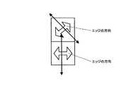
以下、本発明に言うエッジとは、輝度信号の変化の向きを意味し、図2に示すように、テクスチャの方向に対して直角になるものである。 Hereinafter, the edge referred to in the present invention means the direction of change of the luminance signal and is perpendicular to the direction of the texture as shown in FIG.
〔第1の実施形態〕
まず最初に、本発明の第1の実施形態に従ったデブロッキング処理装置1について説明する。[First Embodiment]
First, the
図3に、本発明の第1の実施形態に従ったデブロッキング処理装置1の構成を図示する。 FIG. 3 illustrates the configuration of the
このデブロッキング処理装置1は、図24Aや図24Bに示すような形態で映像符号化装置や映像復号装置に実装されるものである。図3に示すように、本実施形態により構成されるデブロッキング処理装置1は、画素決定部40にて使用するブロック内のエッジ成分を導出して、そのブロック内のエッジの方向を検出するエッジ検出部10と、エッジ検出部10の検出結果を記憶するエッジ方向情報記憶部20と、デブロッキングフィルタの処理対象となる画素(フィルタ処理画素)の決定に用いる情報を記憶するフィルタ処理画素決定用情報記憶部30と、エッジ方向情報記憶部20およびフィルタ処理画素決定用情報記憶部30の記憶する情報を参照することで、エッジ検出部10により検出されたエッジの方向から、実際のフィルタ処理に用いる画素を決定する画素決定部40と、画素決定部40により決定された画素を用いて、フィルタ処理を使用するかどうかを決定するフィルタ使用判定部50と、画素決定部40により決定された画素に対してフィルタ処理を実行するフィルタ処理部60と、MBの最後のブロック境界かどうかを判定することで処理の終了を判断する処理終了判定部70とから構成される。 The
なお、フィルタ処理画素決定用情報記憶部30の記憶するフィルタ処理画素の決定に用いる情報については図18を参照して詳述する。 Information used to determine the filter processing pixel stored in the filter processing pixel determination information storage unit 30 will be described in detail with reference to FIG.
このエッジ検出部10は、図3に示すように、MB内の各ブロックの水平方向のエッジ成分を導出するx方向エッジ成分導出部11と、MB内の各ブロックの垂直方向のエッジ成分を導出するy方向エッジ成分導出部12と、x方向エッジ成分導出部11およびy方向エッジ成分導出部12により導出されたエッジ成分を用いて各ブロックのエッジの方向を決定して、エッジ方向情報記憶部20に保存するエッジ方向決定部13とから構成される。 As shown in FIG. 3, the
また、画素決定部40は、図3に示すように、エッジ方向情報記憶部20の記憶する情報を参照することで、MB内の各ブロック境界に関わるエッジの方向を確認する隣接ブロックエッジ確認部41と、フィルタ処理画素決定用情報記憶部30の記憶する情報を参照することで、隣接ブロックエッジ確認部41により確認されたエッジの方向に基づいて、デブロッキングフィルタの処理対象となる画素を決定するフィルタ処理画素決定部42とから構成される。 Further, as shown in FIG. 3, the pixel determining unit 40 refers to the information stored in the edge direction
図4〜図9に、このように構成される本実施形態のデブロッキング処理装置1が1つのMB内の4×4ブロック境界を処理する場合に実行するフローチャートの一例を図示する。 FIGS. 4 to 9 show examples of flowcharts executed when the
次に、これらのフローチャートに従って、本実施形態のデブロッキング処理装置1の実行する処理について詳細に説明する。 Next, processing executed by the
なお、以下では、特に断りがない限り、ブロックサイズは4×4で、処理対象は輝度信号とする。また、エッジの方向については、4方向(水平(0°)、垂直(90°)、斜め(45°および135°))と仮定する。 In the following, unless otherwise specified, the block size is 4 × 4 and the processing target is a luminance signal. Further, it is assumed that the directions of the edges are four directions (horizontal (0 °), vertical (90 °), oblique (45 ° and 135 °)).
〔1〕本実施形態の実行するフローチャート
〔1−1〕全体的なフローチャート
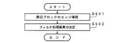
図4に、本実施形態のデブロッキング処理装置1の実行する一連の処理の全体的なフローチャートを図示する。[1] Flowchart Executed by the Present Embodiment [1-1] Overall Flowchart FIG. 4 shows an overall flowchart of a series of processes executed by the
ここで、これから示す処理はMB単位で行い、画像に含まれるMBに対して順番に適用することで実行される。 Here, the processing shown below is performed in units of MB, and is executed by sequentially applying to the MBs included in the image.
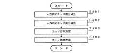
本実施形態のデブロッキング処理装置1は、図4のフローチャートに示すように、まず最初に、ステップS101にて、MB内の16個の4×4ブロックにおける全てのエッジの方向を検出し、その情報をエッジ方向情報記憶部20に保存する。エッジの方向の検出方法については、ステップS201〜ステップS203(図5のフローチャート)で後述する。 As shown in the flowchart of FIG. 4, the
続いて、ステップS102にて、ステップS101で求まったエッジの方向からフィルタ方向の選択を行う。フィルタ方向の選択後、デブロッキングフィルタの処理に必要となる8点の画素を指定する。フィルタ方向の選択と画素の指定の仕方の詳細については、ステップS601〜ステップS602(図9のフローチャート)で後述する。 Subsequently, in step S102, the filter direction is selected from the edge direction obtained in step S101. After selecting the filter direction, 8 pixels necessary for the deblocking filter process are designated. Details of the filter direction selection and pixel designation method will be described later in steps S601 to S602 (flowchart in FIG. 9).
続いて、ステップS103にて、未選択のブロックを1つ選択して、その選択したブロックについて、デブロッキングフィルタ処理の使用有無の判定を行う。これは従来のH.264/AVCに定義されている判定条件を用いる。もしフィルタを使用する場合は、ステップS104に進む。もしフィルタを使用しない場合は、次のブロック処理へ進むために、処理の位置が最終ブロックに到達したかどうかの判定を行うステップS105へ進む。 Subsequently, in step S103, one unselected block is selected, and whether or not the deblocking filter process is used is determined for the selected block. This is the conventional H.264 standard. The determination conditions defined in H.264 / AVC are used. If a filter is used, the process proceeds to step S104. If no filter is used, in order to proceed to the next block process, the process proceeds to step S105 in which it is determined whether or not the position of the process has reached the final block.
続いて、ステップS104にて、ステップS102にて選択された8点の画素を用い、実際にフィルタ処理を実行する。 Subsequently, in step S104, filter processing is actually executed using the eight pixels selected in step S102.
続いて、ステップS105にて、次のブロックへと処理を進めるかどうかの判定を行う。処理対象ブロックが最終ブロックでなければ、そのまま次のブロックへ処理を進めるので、ステップS103の処理へ戻る。最終ブロックまで処理が終わっていれば、処理を終了する。 Subsequently, in step S105, it is determined whether or not the process proceeds to the next block. If the block to be processed is not the final block, the process proceeds to the next block as it is, and the process returns to step S103. If the process has been completed up to the last block, the process ends.
〔1−2〕ステップS101の処理の詳細
〔1−2−1〕ステップS101の全体的な処理
次に、図5のフローチャートに従って、ステップS101にて実行する処理の詳細について説明する。[1-2] Details of processing in step S101 [1-2-1] Overall processing in step S101 Next, details of processing executed in step S101 will be described according to the flowchart of FIG.
本実施形態のデブロッキング処理装置1は、図4のフローチャートのステップS101の処理に入ると、図5のフローチャートに示すように、まず最初に、ステップS201にて、x方向(水平方向)のエッジ成分の導出を行う。続いて、ステップS202にて、y方向(垂直方向)のエッジ成分の導出を行う。続いて、ステップS203にて、ステップS201とステップS202にて求まった各方向のエッジ成分から、ブロックの有するエッジの方向を決定する。 When the
次に、ステップS201、S202、S203の処理の詳細について、それぞれ順番に説明する。 Next, details of the processing of steps S201, S202, and S203 will be described in order.
〔1−2−2〕ステップS201の処理の詳細
図6のフローチャートに従って、ステップS201にて実行する処理の詳細について説明する。[1-2-2] Details of Processing in Step S201 Details of the processing executed in step S201 will be described with reference to the flowchart of FIG.
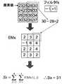
本実施形態のデブロッキング処理装置1は、図5のフローチャートのステップS201の処理に入ると、図6のフローチャートに示すように、まず最初に、ステップS301にて、フィルタfx={−1,1}(図10を参照)を対象ブロックに対して水平方向に施し、得られる行列をエッジマトリクスx(EMx)と定義する(図10を参照)。 When the
続いて、ステップS302にて、ステップS301で得られたEMxに対して、各成分の和を取る。この値をSxとする。Sxはエッジの水平方向成分を示し、プラスならば左から右へ輝度値が上昇する傾向があることを意味し、マイナスの場合は、左から右へ輝度値が減少する傾向があることを意味する。 Then, in step S302, the sum of each component is taken with respect to EMx obtained in step S301. This value is Sx. Sx indicates the horizontal component of the edge. If it is positive, it means that the luminance value tends to increase from left to right, and if it is negative, it means that the luminance value tends to decrease from left to right. To do.
図10に、ステップS201にて実行する処理の概念図を示す。この図10において、4×4ブロックの大きさを持つエッジマトリクスx(EMx)の各要素値をEMx(i,j)とし、iは1以上の整数でx方向の位置を示し、jは1以上の整数でy方向の位置を示す。図10に示すように、例えば、画素値28及び31をそれぞれ有する2つの画素に対してフィルタfx={−1,+1}を施すことで、EMxの成分として30−28=2が得られる。また、EMxの12個の成分の和を取ることで、Sxとして31が得られる。 FIG. 10 shows a conceptual diagram of the process executed in step S201. In FIG. 10, each element value of the edge matrix x (EMx) having a size of 4 × 4 blocks is EMx (i, j), i is an integer of 1 or more and indicates a position in the x direction, and j is 1 The position in the y direction is indicated by the above integer. As shown in FIG. 10, for example, by applying a filter fx = {− 1, + 1} to two pixels each having
〔1−2−3〕ステップS202の処理の詳細
図7のフローチャートに従って、ステップS202にて実行する処理の詳細について説明する。[1-2-3] Details of Processing in Step S202 Details of the processing executed in step S202 will be described according to the flowchart of FIG.
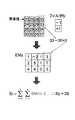
本実施形態のデブロッキング処理装置1は、図5のフローチャートのステップS202の処理に入ると、図7のフローチャートに示すように、まず最初に、ステップS401にて、フィルタfy={−1,1}(図11を参照)を対象ブロックに対して垂直方向に施し、得られる行列をエッジマトリクスy(EMy)と定義する(図11を参照)。 When the
続いて、ステップS402にて、ステップS401で得られたEMyに対して、各成分の和を取る。この値をSyとする。Syはエッジの垂直方向成分を示し、プラスならば上から下へ輝度値が上昇する傾向があることを意味し、マイナスの場合は、上から下へ輝度値が減少する傾向があることを意味する。 Subsequently, in step S402, the sum of each component is calculated with respect to EMy obtained in step S401. This value is Sy. Sy indicates the vertical component of the edge. If it is positive, it means that the luminance value tends to increase from top to bottom, and if it is negative, it means that the luminance value tends to decrease from top to bottom. To do.
図11に、ステップS202にて実行する処理の概念図を示す。この図11において、4×4ブロックの大きさを持つエッジマトリクスy(EMy)の各要素値をEMy(i,j)とし、iは1以上の整数でx方向の位置を示し、jは1以上の整数でy方向の位置を示す。図11に示すように、例えば、画素値30及び33をそれぞれ有する2つの画素に対してフィルタfy={−1,+1}を施すことで、EMyの成分として33−30=3が得られる。また、EMyの12個の成分の和を取ることで、Syとして28が得られる。 FIG. 11 shows a conceptual diagram of the process executed in step S202. In FIG. 11, each element value of the edge matrix y (EMy) having a size of 4 × 4 blocks is EMy (i, j), i is an integer of 1 or more and indicates a position in the x direction, and j is 1 The position in the y direction is indicated by the above integer. As shown in FIG. 11, for example, by applying the filter fy = {− 1, + 1} to two pixels having pixel values 30 and 33, 33-30 = 3 is obtained as the component of EMy. Moreover, 28 is obtained as Sy by taking the sum of 12 components of EMy.
〔1−2−4〕ステップS203の処理の詳細
図8のフローチャートに従って、ステップS203にて実行する処理の詳細について説明する。[1-2-4] Details of Processing in Step S203 Details of the processing executed in step S203 will be described with reference to the flowchart of FIG.
本実施形態のデブロッキング処理装置1は、図5のフローチャートのステップS203の処理に入ると、図8のフローチャートに示すように、まず最初に、ステップS501にて、ステップS302で求めたSxおよびステップS402で求めたSyを、
D=Sy/Sx
という式に代入して、ブロックの有するエッジの角度Dを求める。When the
D = Sy / Sx
The angle D of the edge of the block is obtained by substituting it into the equation.
続いて、ステップS502にて、ステップS501で求めたエッジ角度Dから、エッジの方向を決定する。例えば、エッジの方向が4種類の場合、下記の表2の場合分けにしたがって、エッジの方向(エッジタイプ)を決定する。 Subsequently, in step S502, the edge direction is determined from the edge angle D obtained in step S501. For example, when there are four types of edge directions, the edge direction (edge type) is determined according to the case classification in Table 2 below.
図12に示すように、“D=0.414”はエッジ角度Dが22.5°であること(tan22.5°≒0.414に由来)を意味し、“D=2.414”はエッジ角度Dが67.5°であること(tan67.5°≒2.414に由来)を意味し、“D=−2.414”はエッジ角度Dが112.5°であること(tan112.5°≒−2.414に由来)を意味し、“D=−0.414”はエッジ角度Dが157.5°であること(tan157.5°≒−0.414に由来)を意味している。 As shown in FIG. 12, “D = 0.414” means that the edge angle D is 22.5 ° (derived from tan 22.5 ° ≈0.414), and “D = 2.414” This means that the edge angle D is 67.5 ° (derived from tan 67.5 ° ≈2.414), and “D = −2.414” means that the edge angle D is 112.5 ° (tan 112. “D = −0.414” means that the edge angle D is 157.5 ° (derived from tan157.5 ° ≈−0.414). ing.
これから、表2に示す“D≦−2.414 ,2.414 <D”の指すエッジタイプ3は、図12に示すように、エッジ角度Dが67.5°〜112.5°(247.5°〜292.5°)にあることを意味する(代表角度=90°,270°)。また、表2に示す“−2.414 <D≦−0.414 ”の指すエッジタイプ4は、図12に示すように、エッジ角度Dが112.5°〜157.5°(292.5°〜337.5°)にあることを意味する(代表角度=135°,315°)。また、表2に示す“−0.414 <D≦0.414 ”の指すエッジタイプ1は、図12に示すように、エッジ角度Dが157.5°〜202.5°(337.5°〜22.5°)にあることを意味する(代表角度=0°(=360°),180°)。また、表2に示す“0.414 <D≦2.414 ”の指すエッジタイプ2は、図12に示すように、エッジ角度Dが22.5°〜67.5°(202.5°〜247.5°)にあることを意味する(代表角度=45°,225°)。 As shown in FIG. 12, the
この表2の場合分けにしたがって、例えば、図10および図11に例示したブロックでは、Sx=31で、Sy=28であることで、D=0.90になることから、ステップS502の処理に従って、代表角度が45°,225°となるエッジタイプ2と決定されることになる。 In accordance with the case classification in Table 2, for example, in the blocks illustrated in FIGS. 10 and 11, since Sx = 31 and Sy = 28, D = 0.90. Therefore, according to the process of step S502 The
〔1−3〕ステップS102の処理の詳細
次に、図9のフローチャートに従って、ステップS102にて実行する処理の詳細について説明する。[1-3] Details of Processing in Step S102 Next, details of processing executed in step S102 will be described according to the flowchart of FIG.
本実施形態のデブロッキング処理装置1は、図4のフローチャートのステップS102の処理に入ると、図9のフローチャートに示すように、まず最初に、ステップS601にて、図3に示したエッジ方向情報記憶部20の記憶する情報を参照することで、ステップS101で求めたMB内の全てのブロックについてのエッジ方向の情報を取得して、各ブロック境界面について、どの方向でフィルタを施すかを確認する。 When the
続いて、ステップS602にて、ステップS601で確認したフィルタ方向に沿って、8点の処理対象画素(フィルタ処理画素)を決定する。 Subsequently, in step S602, eight processing target pixels (filter processing pixels) are determined along the filter direction confirmed in step S601.
この処理対象画素(フィルタ処理画素)の決定は、基本的には、図13に示すように、エッジの方向に直交する直線上に並ぶ画素を選ぶことで行う。すなわち、エッジの垂直方向に画像のテクスチャ(線など)があると予測されるため、それに沿う形でフィルタをかけるようにフィルタ処理画素を選ぶ。 This processing target pixel (filter processing pixel) is basically determined by selecting pixels arranged on a straight line orthogonal to the edge direction, as shown in FIG. That is, since it is predicted that there is an image texture (such as a line) in the vertical direction of the edge, a filtering pixel is selected so as to apply a filter along the texture.
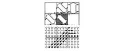
次に、図14A〜図17Gに、水平方向のブロック境界を処理対象とする場合に、処理対象のブロックのエッジの方向と、そのブロックの周辺に位置するブロックのエッジの方向とに応じて、どのような形で8点のフィルタ処理画素を決定するのかということについての具体例を図示する。 Next, in FIGS. 14A to 17G, when a horizontal block boundary is a processing target, depending on the direction of the edge of the processing target block and the direction of the edge of the block located around the block, A specific example of how to determine the eight filtered pixels is shown.
図14A〜図14Eに示す具体例は、処理対象ブロックのエッジの方向がエッジタイプ1である場合に、そのブロックの周辺に位置するブロックのエッジの方向に応じて、どのような形で8点のフィルタ処理画素を決定するのかということについて記載する。 In the specific examples shown in FIGS. 14A to 14E, when the edge direction of the processing target block is the
すなわち、処理対象ブロックのエッジの方向がエッジタイプ1である場合に、処理対象ブロックの上方向に隣接するブロックのエッジの方向がエッジタイプ1またはエッジタイプ3である場合には、図14Aに示すように、従来技術と同じ形態で8点のフィルタ処理画素を決定する。 That is, when the edge direction of the processing target block is
ここで、このときに、上方向に隣接するブロックのエッジの方向がエッジタイプ3である場合に、図13に示す基本的な構成に従ってフィルタ処理画素を選んでいないのは、水平方向に並ぶ画素を選ぶことができないからである。したがって、この場合には、従来技術と同じ形態で8点のフィルタ処理画素を決定することになる。 Here, in this case, when the edge direction of the adjacent block in the upward direction is the
また、処理対象ブロックのエッジの方向がエッジタイプ1である場合に、処理対象ブロックの上方向に隣接するブロックのエッジの方向がエッジタイプ2で、処理対象ブロックの右上方向に隣接するブロックのエッジの方向がエッジタイプ2である場合には、図14Bに示すような形態で8点のフィルタ処理画素を決定することになる。 In addition, when the edge direction of the processing target block is
また、処理対象ブロックのエッジの方向がエッジタイプ1である場合に、処理対象ブロックの上方向に隣接するブロックのエッジの方向がエッジタイプ4で、処理対象ブロックの左上方向に隣接するブロックのエッジの方向がエッジタイプ4である場合には、図14Cに示すような形態で8点のフィルタ処理画素を決定することになる。 In addition, when the edge direction of the processing target block is
また、処理対象ブロックのエッジの方向がエッジタイプ1である場合に、処理対象ブロックの上方向に隣接するブロックのエッジの方向がエッジタイプ2で、処理対象ブロックの右上方向に隣接するブロックのエッジの方向がエッジタイプ3である場合には、図14Dに示すような形態で8点のフィルタ処理画素を決定することになる。 In addition, when the edge direction of the processing target block is
また、処理対象ブロックのエッジの方向がエッジタイプ1である場合に、処理対象ブロックの上方向に隣接するブロックのエッジの方向がエッジタイプ4で、処理対象ブロックの左上方向に隣接するブロックのエッジの方向がエッジタイプ3である場合には、図14Eに示すような形態で8点のフィルタ処理画素を決定することになる。 In addition, when the edge direction of the processing target block is
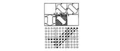
図15A〜図15Gに示す具体例は、処理対象ブロックのエッジの方向がエッジタイプ2である場合に、そのブロックの周辺に位置するブロックのエッジの方向に応じて、どのような形で8点のフィルタ処理画素を決定するのかということについて記載する。 In the specific examples shown in FIGS. 15A to 15G, when the edge direction of the block to be processed is the
図15Aは、処理対象ブロックのエッジの方向がエッジタイプ2で、処理対象ブロックの上方向に隣接するブロックのエッジの方向がエッジタイプ3またはエッジタイプ4の場合の具体例である。図15Aに示すように、これらの場合は、従来技術と同じ形態で8点のフィルタ処理画素を決定する。 FIG. 15A is a specific example when the edge direction of the processing target block is
また、図15Bは、処理対象ブロックのエッジの方向がエッジタイプ2で、処理対象ブロックの上方向に隣接するブロックのエッジの方向がエッジタイプ1で、処理対象ブロックの左方向に隣接するブロックのエッジの方向がエッジタイプ2である場合の具体例である。 FIG. 15B shows that the edge direction of the block to be processed is
また、図15Cは、処理対象ブロックのエッジの方向がエッジタイプ2で、処理対象ブロックの上方向に隣接するブロックのエッジの方向がエッジタイプ2で、処理対象ブロックの右上方向に隣接するブロックのエッジの方向がエッジタイプ2で、処理対象ブロックの左方向に隣接するブロックのエッジの方向がエッジタイプ2である場合の具体例である。 FIG. 15C shows that the edge direction of the block to be processed is
また、図15Dは、処理対象ブロックのエッジの方向がエッジタイプ2で、処理対象ブロックの上方向に隣接するブロックのエッジの方向がエッジタイプ2で、処理対象ブロックの右上方向に隣接するブロックのエッジの方向がエッジタイプ3で、処理対象ブロックの左方向に隣接するブロックのエッジの方向がエッジタイプ2である場合の具体例である。 Further, FIG. 15D shows that the edge direction of the block to be processed is
また、図15Eは、処理対象ブロックのエッジの方向がエッジタイプ2で、処理対象ブロックの上方向に隣接するブロックのエッジの方向がエッジタイプ1で、処理対象ブロックの左方向に隣接するブロックのエッジの方向がエッジタイプ3である場合の具体例である。 In FIG. 15E, the edge direction of the block to be processed is
また、図15Fは、処理対象ブロックのエッジの方向がエッジタイプ2で、処理対象ブロックの上方向に隣接するブロックのエッジの方向がエッジタイプ2で、処理対象ブロックの右上方向に隣接するブロックのエッジの方向がエッジタイプ2で、処理対象ブロックの左方向に隣接するブロックのエッジの方向がエッジタイプ3である場合の具体例である。 In addition, FIG. 15F shows that the edge direction of the block to be processed is
また、図15Gは、処理対象ブロックのエッジの方向がエッジタイプ2で、処理対象ブロックの上方向に隣接するブロックのエッジの方向がエッジタイプ2で、処理対象ブロックの右上方向に隣接するブロックのエッジの方向がエッジタイプ3で、処理対象ブロックの左方向に隣接するブロックのエッジの方向がエッジタイプ3である場合の具体例である。 Further, FIG. 15G shows that the edge direction of the block to be processed is
図16に示す具体例は、処理対象ブロックのエッジの方向がエッジタイプ3である場合に、そのブロックの周辺に位置するブロックのエッジの方向に応じて、どのような形で8点のフィルタ処理画素を決定するのかということについて記載する。 In the specific example shown in FIG. 16, when the direction of the edge of the block to be processed is
この図に示すように、処理対象ブロックのエッジの方向がエッジタイプ3である場合には、処理対象ブロックの上方向に隣接するブロックのエッジの方向がエッジタイプ1、エッジタイプ2、エッジタイプ3、エッジタイプ4のいずれにある場合も、従来技術と同じ形態で8点のフィルタ処理画素を決定することになる。 As shown in this figure, when the direction of the edge of the processing target block is
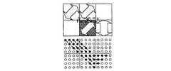
図17A〜図17Gに示す具体例は、処理対象ブロックのエッジの方向がエッジタイプ4である場合に、そのブロックの周辺に位置するブロックのエッジの方向に応じて、どのような形で8点のフィルタ処理画素を決定するのかということについて記載する。 In the specific examples shown in FIGS. 17A to 17G, when the edge direction of the processing target block is the
図17Aは、処理対象ブロックのエッジの方向がエッジタイプ4で、処理対象ブロックの上方向に隣接するブロックのエッジの方向がエッジタイプ3またはエッジタイプ2の場合の具体例である。図17Aに示すように、これらの場合は、従来技術と同じ形態で8点のフィルタ処理画素を決定する。 FIG. 17A is a specific example in the case where the edge direction of the processing target block is
また、図17Bは、処理対象ブロックのエッジの方向がエッジタイプ4で、処理対象ブロックの上方向に隣接するブロックのエッジの方向がエッジタイプ1で、処理対象ブロックの右方向に隣接するブロックのエッジの方向がエッジタイプ4である場合の具体例である。 In FIG. 17B, the direction of the edge of the processing target block is
また、図17Cは、処理対象ブロックのエッジの方向がエッジタイプ4で、処理対象ブロックの上方向に隣接するブロックのエッジの方向がエッジタイプ4で、処理対象ブロックの左上方向に隣接するブロックのエッジの方向がエッジタイプ4で、処理対象ブロックの右方向に隣接するブロックのエッジの方向がエッジタイプ4である場合の具体例である。 In FIG. 17C, the edge direction of the block to be processed is
また、図17Dは、処理対象ブロックのエッジの方向がエッジタイプ4で、処理対象ブロックの上方向に隣接するブロックのエッジの方向がエッジタイプ4で、処理対象ブロックの左上方向に隣接するブロックのエッジの方向がエッジタイプ3で、処理対象ブロックの右方向に隣接するブロックのエッジの方向がエッジタイプ4である場合の具体例である。 In FIG. 17D, the edge direction of the block to be processed is
また、図17Eは、処理対象ブロックのエッジの方向がエッジタイプ4で、処理対象ブロックの上方向に隣接するブロックのエッジの方向がエッジタイプ1で、処理対象ブロックの右方向に隣接するブロックのエッジの方向がエッジタイプ3である場合の具体例である。 In FIG. 17E, the edge direction of the block to be processed is
また、図17Fは、処理対象ブロックのエッジの方向がエッジタイプ4で、処理対象ブロックの上方向に隣接するブロックのエッジの方向がエッジタイプ4で、処理対象ブロックの左上方向に隣接するブロックのエッジの方向がエッジタイプ4で、処理対象ブロックの右方向に隣接するブロックのエッジの方向がエッジタイプ3である場合の具体例である。 In FIG. 17F, the direction of the edge of the processing target block is
また、図17Gは、処理対象ブロックのエッジの方向がエッジタイプ4で、処理対象ブロックの上方向に隣接するブロックのエッジの方向がエッジタイプ4で、処理対象ブロックの左上方向に隣接するブロックのエッジの方向がエッジタイプ3で、処理対象ブロックの右方向に隣接するブロックのエッジの方向がエッジタイプ3である場合の具体例である。 In FIG. 17G, the edge direction of the block to be processed is
このようにして、図4のフローチャートのステップS102では、図9のフローチャートを実行することで、MB内ブロックのエッジの方向に基づいて、図14A〜図17Gに示すような形態でデブロッキングフィルタの処理対象となるフィルタ処理画素を決定するように処理する。 In this way, in step S102 of the flowchart of FIG. 4, by executing the flowchart of FIG. 9, the deblocking filter is executed in the form as shown in FIGS. 14A to 17G based on the edge direction of the block in the MB. Processing is performed so as to determine a filtering pixel to be processed.
なお、図14A〜図17Gでは、発生するテクスチャの状況(頻度)を考慮して代表的な具体例を示したが、これら以外の具体例についても、図14A〜図17Gに示した具体例に準じてデブロッキングフィルタの処理対象となるフィルタ処理画素を決定することができる。 In FIGS. 14A to 17G, typical specific examples are shown in consideration of the state (frequency) of the generated texture, but other specific examples are also shown in the specific examples shown in FIGS. 14A to 17G. Accordingly, it is possible to determine the filter processing pixel to be processed by the deblocking filter.
例えば、図14Bにおける処理対象ブロックの右上方向に隣接するブロックのエッジの方向が、エッジタイプ2ではなくエッジタイプ1である場合には、従来技術と同じ形態で8点のフィルタ処理画素を決定する。その理由は、テクスチャが、処理対象ブロックの上方向に隣接するブロックと処理対象ブロックの右上方向に隣接するブロックとの間で途切れてしまうため、デブロッキングフィルタ処理を施さない方が良いと判断されるためである。 For example, when the edge direction of the block adjacent to the upper right direction of the processing target block in FIG. 14B is not edge
一方、例えば、図14Bにおける処理対象ブロックの右上方向に隣接するブロックのエッジの方向が、エッジタイプ2ではなくエッジタイプ4である場合、テクスチャが右上に伸びるところを強制的に左下へ向かわせることになる。すなわち、テクスチャは“/\”のように曲がることになる。なお、この場合は、処理対象ブロックの右方向に隣接するブロックについてもエッジの方向を判定することになる。テクスチャが“<”あるいは“>”のように曲がる場合も含めて、テクスチャが急峻に変化する状況(頻度)はあまりないと予想されるが、こうした場合にもデブロッキングフィルタ処理を施すことが可能である。 On the other hand, for example, when the edge direction of the block adjacent to the upper right direction of the processing target block in FIG. 14B is
要するに、画像のテクスチャ(線など)がエッジに対して垂直方向に現れるという想定の下で、テクスチャの線分が遮断される状況は効率低下を招く可能性があるため、デブロッキングフィルタ処理を施す候補から外すということになる。 In short, under the assumption that the texture (lines, etc.) of the image appears in the direction perpendicular to the edges, the situation where the texture line segments are blocked may cause a decrease in efficiency. It will be removed from the candidate.
ここで、図14A〜図17Gでは、水平方向のブロック境界を処理対象とする場合に、処理対象のブロックのエッジの方向と、そのブロックに隣接するブロックのエッジの方向とに応じて、どのような形で8点のフィルタ処理画素を決定するのかということについて説明したが、垂直方向のブロック境界を処理対象とする場合も、同様にして8点のフィルタ処理画素を決定することになる。すなわち、垂直方向のブロック境界を処理対象とする場合には、図14A〜図17Gを90°だけ傾ける形で同様に処理できる。 Here, in FIGS. 14A to 17G, when a horizontal block boundary is set as a processing target, depending on an edge direction of a processing target block and an edge direction of a block adjacent to the processing block, how In the above description, the eight filtering pixels are determined. However, when the vertical block boundary is a processing target, the eight filtering pixels are determined in the same manner. That is, when the block boundary in the vertical direction is to be processed, the processing can be similarly performed by tilting FIGS. 14A to 17G by 90 °.
以上に説明したように、図4のフローチャートのステップS102では、図9のフローチャートを実行することで、処理対象ブロックおよびその周辺に位置するブロック(上下左右斜め方向に接するブロック)のエッジの方向に基づいて、図14A〜図17Gに示すような形態で8点のフィルタ処理画素を決定することになる。この決定処理を実現するために、図3に示したフィルタ処理画素決定用情報記憶部30が用意される。 As described above, in step S102 of the flowchart of FIG. 4, by executing the flowchart of FIG. Based on this, eight filtering pixels are determined in the form shown in FIGS. 14A to 17G. In order to realize this determination process, the filter processing pixel determination information storage unit 30 shown in FIG. 3 is prepared.
図18に、フィルタ処理画素を決定するために用意されるフィルタ処理画素決定用情報記憶部30のデータ構造の一例を図示する。 FIG. 18 shows an example of the data structure of the filtering pixel determination information storage unit 30 prepared for determining filtering pixels.
この図に示すように、フィルタ処理画素決定用情報記憶部30は、処理対象となるブロック境界が水平方向である場合に、処理対象ブロックのエッジタイプ(エッジの方向)の値と、周辺のブロックのエッジタイプの値との組み合わせのそれぞれについて、フィルタ処理画素として決定される画素の位置を記述した位置情報を記憶する。また、フィルタ処理画素決定用情報記憶部30は、処理対象となるブロック境界が垂直方向である場合に、処理対象ブロックのエッジタイプの値と、周辺のブロックのエッジタイプの値との組み合わせのそれぞれについて、フィルタ処理画素として決定される画素の位置を記述した位置情報を記憶する。 As shown in this figure, when the block boundary to be processed is the horizontal direction, the filter processing pixel determination information storage unit 30 determines the edge type (edge direction) value of the processing target block and the surrounding blocks. For each combination with the edge type value, position information describing the position of the pixel determined as the filter processing pixel is stored. In addition, the filter processing pixel determination information storage unit 30 is configured so that each of the combinations of the edge type value of the processing target block and the edge type values of the surrounding blocks when the block boundary to be processed is in the vertical direction. Is stored with position information describing the position of the pixel determined as the filtering pixel.
このようなデータ構造を持つフィルタ処理画素決定用情報記憶部30を設けて、ステップS601において、図3に示したエッジ方向情報記憶部20の記憶する情報を参照することで、処理対象ブロックおよびその周辺に位置するブロックのエッジタイプを特定すると、ステップS602では、その特定したエッジタイプ情報および処理対象のブロック境界の方向情報をキーにして、フィルタ処理画素決定用情報記憶部30の記憶する情報を参照することで、8点のフィルタ処理画素を決定する。 By providing the filter processing pixel determination information storage unit 30 having such a data structure and referring to the information stored in the edge direction
〔1−4〕ステップS103,ステップS104の処理
ステップS103では、デブロッキングフィルタ処理の使用有無の判定を行う。これは従来のH.264/AVCに定義されている判定条件を用いる。[1-4] Steps S103 and S104 In step S103, it is determined whether or not the deblocking filter process is used. This is the conventional H.264 standard. The determination conditions defined in H.264 / AVC are used.
ステップS103でデブロッキングフィルタ処理の使用を決定する場合には、続いて、ステップS104で、ステップS102で決定したフィルタ処理画素に対して、従来のH.264/AVCに定義されているデブロッキングフィルタ処理を施す。 If it is determined in step S103 that the deblocking filter process is to be used, then in step S104, the conventional H.264 filter is applied to the filter processing pixel determined in step S102. Deblocking filter processing defined in H.264 / AVC is performed.
従来のデブロッキングフィルタではブロック境界に対して垂直方向の8点4組の画素しか変更が行えなかったが、以上に説明した本発明の実施形態により斜め方向のデブロッキングフィルタ処理が可能となる。これにより、本発明が解決しようとする課題に対応できることになって、主観画質の向上と符号化効率の向上が見込めることになる。 In the conventional deblocking filter, only eight sets of four pixels in the vertical direction with respect to the block boundary can be changed. However, the deblocking filter processing in the oblique direction can be performed according to the embodiment of the present invention described above. As a result, the problem to be solved by the present invention can be addressed, and an improvement in subjective image quality and an improvement in coding efficiency can be expected.
以上、4×4ブロックについての説明を行ったが、4×4ブロック以外の大きさにも本発明の概念は適用可能である。また、輝度信号だけでなく、色差信号に対しても同様に適用可能である。 The 4 × 4 block has been described above, but the concept of the present invention can be applied to sizes other than the 4 × 4 block. Further, the present invention can be similarly applied not only to a luminance signal but also to a color difference signal.
〔2〕本実施形態の有効性を検証するために行った実験について
次に、本実施形態の有効性を検証するために行った実験結果について説明する。[2] Experiments performed to verify the effectiveness of the present embodiment Next, results of experiments performed to verify the effectiveness of the present embodiment will be described.
この実験は、標準化で利用されている標準画像Foreman について、本実施形態を実装して画像品質を検証することで行った。具体的な実験条件は下記の通りである。 This experiment was performed by implementing this embodiment and verifying image quality for a standard image Foreman used in standardization. Specific experimental conditions are as follows.
・使用ソフトウェア: KTA(Key Technical Area) ver. 1.8
・画像種類 : Foreman
・画像サイズ : QCIF(176×144)
・GOP構造 : III...(All intra coded)
・量子化パラメータ: 37(固定)
・エッジ方向 : 4
・フレーム枚数 : 10
・フレームスキップ: 1
なお、画像とソフトウェアについては、
・http://media.xiph.org/video/derf/ (標準画像)
・http://iphome.hhi.de/suehring/tml/download/KTA/ (ソフトウェア)
にてそれぞれ入手できる。-Software used: KTA (Key Technical Area) ver. 1.8
・ Image type: Foreman
・ Image size: QCIF (176 × 144)
・ GOP structure: III ... (All intra coded)
・ Quantization parameter: 37 (fixed)
・ Edge direction: 4
・ Number of frames: 10
・ Frame skip: 1
For images and software,
・ Http://media.xiph.org/video/derf/ (Standard image)
・ Http://iphome.hhi.de/suehring/tml/download/KTA/ (software)
Available at
図19Aに、実験により得られた標準画像Foreman についてのフレーム単位の客観画質PSNR(Peak Signal-to-Noise Ratio)値を図示し、図19Bに、それをグラフ化したデータを図示する。ここで、図19Bにおいて、横軸は処理フレーム番号を示し、縦軸は該当フレームにおける客観画質(PSNR)を示す。また、凡例のNormalは従来のデブロッキングフィルタを意味しており、EADF(Edge Adaptive Deblocking Filter )は本実施形態によるフィルタを意味する。 FIG. 19A illustrates an objective image quality PSNR (Peak Signal-to-Noise Ratio) value for a standard image Foreman obtained by experiment, and FIG. 19B illustrates data obtained by graphing it. Here, in FIG. 19B, the horizontal axis indicates the processing frame number, and the vertical axis indicates the objective image quality (PSNR) in the corresponding frame. In addition, Normal in the legend means a conventional deblocking filter, and EADDF (Edge Adaptive Deblocking Filter) means a filter according to the present embodiment.
この実験結果により、本実施形態を利用することで画質が向上していることを確認でき、本実施形態の有効性を検証できた。 From this experimental result, it was confirmed that the image quality was improved by using this embodiment, and the effectiveness of this embodiment could be verified.
〔第2の実施形態〕
次に、本発明の第2の実施形態に従ったデブロッキング処理装置1について説明する。[Second Embodiment]
Next, the
本発明の第1の実施形態ではエッジの方向に直交する直線上に並ぶ画素を使ってデブロッキング処理を実行する構成を採ることから、斜めのエッジを有する画像については、その画質を向上させることができるものの、複雑なテクスチャを有する画像については、フレームによっては画質が劣化することも考えられる。 The first embodiment of the present invention adopts a configuration in which deblocking processing is performed using pixels arranged on a straight line orthogonal to the edge direction, so that the image quality of an image having an oblique edge is improved. However, for an image having a complicated texture, the image quality may be deteriorated depending on the frame.
そこで、第2の実施形態では、この点を考慮して、各ブロックについてエッジの強度を求めるようにして、その求めたエッジの強度が大きい処理対象ブロック、すなわち、斜めの強い(鮮明な)エッジを有する画像については、第1の実施形態と同様のデブロッキングフィルタを利用してデブロッキング処理を実行し、一方、その求めたエッジの強度が小さい処理対象ブロック、すなわち、複雑なテクスチャを有する画像、もしくはエッジが弱い(目立たない)画像については、従来技術によるデブロッキングフィルタを利用してデブロッキング処理を実行するという構成を採る。 Therefore, in the second embodiment, in consideration of this point, the edge strength is obtained for each block, and the processing target block having the obtained edge strength is large, that is, the diagonally strong (clear) edge. As for the image having, the deblocking process is executed using the same deblocking filter as in the first embodiment. On the other hand, the obtained processing target block having a small edge strength, that is, an image having a complex texture. Alternatively, for an image with weak edges (not conspicuous), a configuration is employed in which deblocking processing is performed using a deblocking filter according to the prior art.
図20に、本発明の第2の実施形態に従ったデブロッキング処理装置1の構成を図示する。 FIG. 20 illustrates a configuration of a
本実施形態のデブロッキング処理装置1は、第1の実施形態の備えるエッジ方向決定部13に代えてエッジ方向決定部13αを備え、第1の実施形態の備えるエッジ方向情報記憶部20に代えてエッジ方向強度情報記憶部20αを備え、第1の実施形態の備える画素決定部40がさらにエッジ強度判定部43とフィルタ処理画素最終決定部44とを備えるという構成を採る。 The
このエッジ方向決定部13αは、x方向エッジ成分導出部11およびy方向エッジ成分導出部12により導出されたエッジ成分を用いて各ブロックのエッジの方向を決定することに加えて、そのエッジの強度を算出して、それらの情報をエッジ方向強度情報記憶部20αに保存する。 The edge direction determination unit 13α determines the edge direction of each block using the edge components derived by the x-direction edge
また、エッジ強度判定部43は、エッジ方向強度情報記憶部20αの記憶する情報を参照することで、MB内の各ブロックのエッジの強度を取得して、それを所定の閾値と比較することで、MB内の各ブロックのエッジの強度が大きいものであるのか否かを判定する。 The edge strength determination unit 43 obtains the edge strength of each block in the MB by referring to the information stored in the edge direction strength information storage unit 20α, and compares it with a predetermined threshold value. , It is determined whether the edge strength of each block in the MB is large.
また、フィルタ処理画素最終決定部44は、エッジ強度判定部43によりエッジの強度が小さいと判定されたブロックについて、フィルタ処理画素決定部42の決定したフィルタ処理画素を、従来技術で使われているフィルタ処理画素(ブロック境界の方向に直交する直線上に並ぶ画素で構成されるフィルタ処理画素)に変更する。 Further, the filter processing pixel final determination unit 44 uses the filter processing pixel determined by the filter processing pixel determination unit 42 for the block determined to have a low edge strength by the edge strength determination unit 43 in the prior art. Change to a filter processing pixel (filter processing pixel composed of pixels arranged on a straight line orthogonal to the direction of the block boundary).
図21および図22に、本実施形態のデブロッキング処理装置1が1つのMB内の4×4ブロック境界を処理する場合に実行するフローチャートの一例を図示する。 FIG. 21 and FIG. 22 show an example of a flowchart executed when the
次に、これらのフローチャートに従って、本実施形態のデブロッキング処理装置1の実行する処理について詳細に説明する。 Next, processing executed by the
なお、以下では、特に断りがない限り、ブロックサイズは4×4で、処理対象は輝度信号とする。また、エッジの方向については、4方向(水平(0°)、垂直(90°)、斜め(45°および135°))と仮定する。 In the following, unless otherwise specified, the block size is 4 × 4 and the processing target is a luminance signal. Further, it is assumed that the directions of the edges are four directions (horizontal (0 °), vertical (90 °), oblique (45 ° and 135 °)).
本実施形態のデブロッキング処理装置1は、図21のフローチャートに示すように、まず最初に、ステップS701にて、MB内の16個の4×4ブロックにおける全てのエッジの方向および強度を検出し、その情報をエッジ方向強度情報記憶部20αに保存する。第1の実施形態と異なる点は、エッジの強度を導出する処理が加わる点である。エッジの方向および強度の検出方法については、ステップS801〜ステップS804(図22のフローチャート)で後述する。 As shown in the flowchart of FIG. 21, the
続いて、ステップS702にて、ステップS701で求まったエッジの方向からフィルタ方向の選択を行う。フィルタ方向の選択後、デブロッキングフィルタの処理に必要となる8点の画素を指定する。フィルタ方向の選択と画素の指定の仕方の詳細については、ステップS601〜ステップS602(図9のフローチャート)で説明した通りである。 In step S702, the filter direction is selected from the edge direction obtained in step S701. After selecting the filter direction, 8 pixels necessary for the deblocking filter process are designated. The details of how to select the filter direction and specify the pixel are as described in Steps S601 to S602 (the flowchart of FIG. 9).
続いて、ステップS703にて、処理対象ブロックを1つ選択して(MB内でフィルタをかける処理の位置順序はH.264/AVCに基づく)、その選択したブロックについて、ステップS701にて導出されたエッジの強度と所定の閾値との比較を行う。エッジの強度が閾値よりも大きければ、エッジが強く、テクスチャが斜め方向に現れると判断して、ステップS702で決定されたフィルタ処理画素を最終的なフィルタ処理画素として決定して、ステップS704の処理を実行することなくステップS705へ進む。 Subsequently, in step S703, one processing target block is selected (the position order of the filtering process in the MB is based on H.264 / AVC), and the selected block is derived in step S701. The intensity of the edge is compared with a predetermined threshold value. If the edge strength is greater than the threshold value, it is determined that the edge is strong and the texture appears in an oblique direction, and the filtering pixel determined in step S702 is determined as the final filtering pixel, and the processing in step S704 is performed. Without proceeding to step S705.
一方、エッジの強度が閾値よりも小さいか等しければ、エッジが弱く、テクスチャが斜め方向に現われていないと判断して、ステップS702で決定されたフィルタ処理画素を変更すべくステップS704に進む。ステップS704にて、従来技術と同様に、ブロック境界の方向に直交する直線上に並ぶ画素を最終的なフィルタ処理画素として決定することで、デブロッキングフィルタの処理に必要となる8点の画素を指定する。つまり、ステップ702で選択したフィルタ方向をブロック境界に直交する方向に変更する。 On the other hand, if the intensity of the edge is less than or equal to the threshold value, it is determined that the edge is weak and the texture does not appear in the oblique direction, and the process proceeds to step S704 to change the filtering pixel determined in step S702. In step S704, as in the related art, by determining pixels arranged on a straight line orthogonal to the direction of the block boundary as final filter processing pixels, eight pixels necessary for deblocking filter processing are determined. specify. That is, the filter direction selected in step 702 is changed to a direction orthogonal to the block boundary.
ステップS703,ステップS704の処理を終えると、続いて、ステップS705にて、デブロッキングフィルタ処理の使用有無の判定を行う。これは従来のH.264/AVCに定義されている判定条件を用いる。もしフィルタを使用する場合は、ステップS706に進む。もしフィルタを使用しない場合は、次のブロック処理へ進むために、処理の位置が最終ブロックに到達したかどうかの判定を行うステップS707へ進む。 When the processes in steps S703 and S704 are finished, subsequently, in step S705, it is determined whether or not the deblocking filter process is used. This is the conventional H.264 standard. The determination conditions defined in H.264 / AVC are used. If a filter is used, the process proceeds to step S706. If the filter is not used, the process proceeds to step S707 for determining whether or not the position of the process has reached the final block in order to proceed to the next block process.
続いて、ステップS706にて、ステップS704の処理を行わないブロックについては、ステップS702にて決定された8点の画素を用いて実際にフィルタ処理(すなわち、第1の実施形態と同様の斜め方向のフィルタ処理)を実行する。一方、ステップS704の処理を行ったブロックについては、ステップS704にて決定された8点の画素を用いて実際にフィルタ処理(すなわち、従来技術と同様のブロック境界に対して垂直方向のみのフィルタ処理)をステップS706にて実行する。 Subsequently, in step S706, for the blocks that are not subjected to the processing in step S704, the filter processing is actually performed using the eight pixels determined in step S702 (that is, the diagonal direction similar to that in the first embodiment). Filter processing). On the other hand, for the block that has undergone the processing in step S704, the actual filtering process using the eight pixels determined in step S704 (that is, the filtering process only in the vertical direction with respect to the block boundary similar to the conventional technique). ) Is executed in step S706.
続いて、ステップS707にて、次のブロックへと処理を進めるかどうかの判定を行う。処理対象ブロックが最終ブロックでなければ、そのまま次のブロックへ処理を進めるので、ステップS703の処理へ戻る。最終ブロックまで処理が終わっていれば、処理を終了する。 Subsequently, in step S707, it is determined whether or not to proceed to the next block. If the processing target block is not the final block, the process proceeds to the next block as it is, and the process returns to step S703. If the process has been completed up to the last block, the process ends.
次に、図22のフローチャートに従って、ステップS701にて実行する処理の詳細について説明する。 Next, details of the process executed in step S701 will be described with reference to the flowchart of FIG.
本実施形態のデブロッキング処理装置1は、図21のフローチャートのステップS701の処理に入ると、図22のフローチャートに示すように、まず最初に、ステップS801にて、x方向(水平方向)のエッジ成分の導出を行う。この処理の詳細は、第1の実施形態のステップS301〜ステップS302で詳説した通りである。 When the
続いて、ステップS802にて、y方向(垂直方向)のエッジ成分の導出を行う。この処理の詳細は、第1の実施形態のステップS401〜ステップS402で詳説した通りである。 Subsequently, in step S802, an edge component in the y direction (vertical direction) is derived. Details of this processing are as described in detail in steps S401 to S402 of the first embodiment.
続いて、ステップS803にて、ステップS801で求めたエッジの水平方向成分の和SxおよびステップS802で求めたエッジの垂直方向成分の和Syから、ブロックの有するエッジの角度Dを求めて、それに基づいてエッジの方向を決定する。この処理の詳細は、第1の実施形態のステップS501〜ステップS502で詳説した通りである。 Subsequently, in step S803, the edge angle D of the block is obtained from the sum Sx of the horizontal components of the edges obtained in step S801 and the sum Sy of the vertical components of the edges obtained in step S802. To determine the edge direction. Details of this processing are as described in detail in steps S501 to S502 of the first embodiment.
続いて、ステップS804にて、ステップS801で求めたエッジの水平方向成分の和SxおよびステップS802で求めたエッジの垂直方向成分の和Syを、
M=(Sx2+Sy2)1/2
という式に代入して、ブロックの有するエッジの強度Mを算出する。Subsequently, in step S804, the sum Sx of the horizontal component of the edge obtained in step S801 and the sum Sy of the vertical component of the edge obtained in step S802 are obtained.
M = (Sx2 + Sy2 )1/2
By substituting into the expression, the edge strength M of the block is calculated.
なお、図21のフローチャートのステップS703で用いるエッジの強度と比較することになる閾値は、複数の符号化対象映像からフレームを取り、それらのフレームの有するエッジ強度の平均値を算出することなどで決定することが可能である。 The threshold to be compared with the edge strength used in step S703 in the flowchart of FIG. 21 is obtained by taking a frame from a plurality of encoding target videos and calculating an average value of the edge strengths of the frames. It is possible to determine.
以上に説明した本実施形態により、エッジの強度を考慮して、エッジの方向に対応したデブロッキングフィルタ処理が可能となる。これにより、エッジの強度を考慮せずに、エッジの強度が弱くてもエッジの方向からフィルタ方向を決めるという構成を採る第1の実施形態に比べて、特に強い斜め方向のテクスチャが存在し、その部分のみにフィルタ処理画素の方向を変えたい場合に有効な方法となる。 According to the present embodiment described above, the deblocking filter processing corresponding to the edge direction can be performed in consideration of the edge strength. Thereby, there is a particularly strong texture in the oblique direction compared to the first embodiment in which the filter direction is determined from the edge direction even if the edge strength is weak, without considering the edge strength, This is an effective method when it is desired to change the direction of the filtering pixel only in that portion.
〔第3の実施形態〕
次に、本発明の第3の実施形態に従ったデブロッキング処理装置1について説明する。[Third Embodiment]
Next, the
本実施形態と第2の実施形態との違いは、ステップS701に該当するエッジ方向の検出方法と、ステップS703に該当するエッジ強度を用いた判定方法とが異なる点である。なお、本実施形態に従ったデブロッキング処理装置の構成は、第2の実施形態に従ったデブロッキング処理装置(図20を参照)の構成と同様である。 The difference between the present embodiment and the second embodiment is that the edge direction detection method corresponding to step S701 is different from the determination method using the edge strength corresponding to step S703. In addition, the structure of the deblocking processing apparatus according to this embodiment is the same as that of the deblocking processing apparatus (refer FIG. 20) according to 2nd Embodiment.
まず、図23のフローチャートに従って、ステップS701に対しての変更内容について詳説する。本実施形態では、イントラ予測情報を利用してエッジの方向を検出するようにしている。 First, according to the flowchart of FIG. 23, the details of changes to step S701 will be described in detail. In the present embodiment, the direction of the edge is detected using intra prediction information.
なお、以下では、特に断りがない限り、ブロックサイズは4×4で、処理対象は輝度信号とする。また、エッジの方向については、4方向(水平(0°)、垂直(90°)、斜め(45°および135°))と仮定する。 In the following, unless otherwise specified, the block size is 4 × 4 and the processing target is a luminance signal. Further, it is assumed that the directions of the edges are four directions (horizontal (0 °), vertical (90 °), oblique (45 ° and 135 °)).
本実施形態のデブロッキング処理装置1では、エッジの方向を検出する場合、図23のフローチャートに示すように、まず最初に、ステップS901にて、処理対象MBがイントラ予測で符号化されているのかどうかを判定する。もしもイントラ予測符号化されていた場合は、ステップS902に進み、MB内のイントラ予測の予測モード情報を取得する。 In the
一方、処理対象MBがイントラ予測で符号化されているのではなくてインター予測で符号化されていた場合は、ステップS903へ進み、処理対象MBのイントラ予測を実行する。そして、ステップS903が終了したら、続いてステップS904へ進み、そのイントラ予測で得られた予測モード情報を取得する。 On the other hand, when the processing target MB is not encoded by intra prediction but encoded by inter prediction, the process proceeds to step S903, and intra prediction of the processing target MB is executed. When step S903 is completed, the process proceeds to step S904, and the prediction mode information obtained by the intra prediction is acquired.
続いて、ステップS905にて、ステップS902またはS904で取得した予測モード情報に従って、エッジの方向の決定を行う。このエッジの方向の決定には、予測モードとエッジの方向との対応表である下記の表3を用いる。 Subsequently, in step S905, the edge direction is determined according to the prediction mode information acquired in step S902 or S904. For the determination of the edge direction, the following Table 3 which is a correspondence table between the prediction mode and the edge direction is used.
例えば、予測モードが0の場合、H.264/AVCにおいては垂直予測が選ばれているため、同様の画素値を持つ画素のラインが垂直方向に伸びていると予想される。従って画像のテクスチャが垂直方向にあるため、エッジは水平方向、すなわち、第1の実施形態における図12のエッジタイプ1に相当すると予想される。また、予測モードが2の場合は、MBが平均値予測されるため、エッジはないかあるいは非常に弱いと考えられ、エッジの方向をNonと判定する。 For example, when the prediction mode is 0, H. In H.264 / AVC, since vertical prediction is selected, it is expected that lines of pixels having similar pixel values extend in the vertical direction. Therefore, since the texture of the image is in the vertical direction, the edge is expected to correspond to the horizontal direction, that is, the
このようにして、本実施形態では、処理対象MBをイントラ予測した場合の予測モードからエッジの方向を推定する。 Thus, in this embodiment, the direction of the edge is estimated from the prediction mode when the processing target MB is intra-predicted.
次に、ステップS703に対しての変更内容について詳説する。 Next, details of changes made to step S703 will be described.
本実施形態のデブロッキング処理装置1では、ステップS905にてエッジの方向がNonと判定された場合は、エッジの強度が閾値以下になるとみなし、ステップS704へ進むことで、従来のデブロッキングフィルタと同様の方向の処理にする。それ以外の場合については、ステップS704の処理を行わないことで、エッジの方向に従ってデブロッキングフィルタ処理を行う。 In the
以上に説明した本実施形態により、第2の実施形態と同様に、エッジの強度を考慮して、エッジの方向に対応したデブロッキングフィルタ処理が可能となる。これにより、エッジの強度を考慮せずに、エッジの強度が弱くてもエッジの方向からフィルタ方向を決めるという構成を採る第1の実施形態に比べて、特に強い斜め方向のテクスチャが存在し、その部分のみにフィルタ処理画素の方向を変えたい場合に有効な方法となる。 According to the present embodiment described above, the deblocking filter process corresponding to the edge direction can be performed in consideration of the edge strength, as in the second embodiment. Thereby, there is a particularly strong texture in the oblique direction compared to the first embodiment in which the filter direction is determined from the edge direction even if the edge strength is weak, without considering the edge strength, This is an effective method when it is desired to change the direction of the filtering pixel only in that portion.
なお、上記で説明した各処理ステップを実現するためのプログラムをコンピュータ読み取り可能な記録媒体に記録して、この記録媒体に記録されたプログラムをコンピュータシステムに読み込ませ、実行することにより、映像符号化装置に係る上述した種々の処理を行ってもよい。 The program for realizing each processing step described above is recorded on a computer-readable recording medium, and the program recorded on the recording medium is read into a computer system and executed, whereby video encoding is performed. You may perform the various process which concerns on the apparatus mentioned above.
ここでいうコンピュータシステムとは、OS(オペレーティングシステム)や周辺機器等のハードウェアを含むものであってもよい。また、コンピュータシステムは、WWW(ワールドワイドウェブ)システムを利用している場合であれば、ホームページ提供環境(あるいは表示環境)も含むものとする。 The computer system referred to here may include an OS (operating system) and hardware such as peripheral devices. The computer system also includes a homepage providing environment (or display environment) if a WWW (World Wide Web) system is used.
コンピュータ読み取り可能な記録媒体とは、フレキシブルディスク、光磁気ディスク、ROM(Read Only Memory)、フラッシュメモリ等の書き込み可能な不揮発性メモリ、CD(コンパクトディスク)−ROM等の可搬媒体、コンピュータシステムに内蔵されるハードディスク等の記憶装置のことをいう。また、コンピュータ読み取り可能な記録媒体とは、インターネット等のネットワークや電話回線等の通信回線を介してプログラムが送信された場合のサーバやクライアントとなるコンピュータシステム内部の揮発性メモリ(例えばDRAM(Dynamic Random Access Memory))のように、一定時間プログラムを保持しているものも含むものとする。 Computer-readable recording media include flexible disks, magneto-optical disks, ROM (Read Only Memory), writable non-volatile memory such as flash memory, portable media such as CD (Compact Disk) -ROM, and computer systems. A built-in storage device such as a hard disk. The computer-readable recording medium is a volatile memory (eg, DRAM (Dynamic Random) inside a computer system that becomes a server or client when a program is transmitted via a network such as the Internet or a communication line such as a telephone line. Access Memory)) is also included, which holds a program for a certain period of time.
上記プログラムは、このプログラムを記憶装置等に格納したコンピュータシステムから、伝送媒体を介してあるいは伝送媒体中の伝送波により、他のコンピュータシステムに伝送されてもよい。ここで、プログラムを伝送する伝送媒体は、インターネット等のネットワーク(通信網)や電話回線等の通信回線(通信線)のように情報を伝送する機能を有する媒体のことをいう。また、上記プログラムは、前述した機能の一部を実現するためのものであって良い。さらに、前述した機能をコンピュータシステムにすでに記録されているプログラムとの組み合わせで実現できるもの、いわゆる差分ファイル(差分プログラム)であって良い。 The program may be transmitted from a computer system storing the program in a storage device or the like to another computer system via a transmission medium or by a transmission wave in the transmission medium. Here, the transmission medium for transmitting the program refers to a medium having a function of transmitting information, such as a network (communication network) such as the Internet or a communication line (communication line) such as a telephone line. The program may be for realizing a part of the functions described above. Furthermore, what can implement | achieve the function mentioned above in combination with the program already recorded on the computer system, and what is called a difference file (difference program) may be sufficient.
以上、本発明の実施形態を説明したが、本発明は上述した実施形態に限定されるものではなく、本発明の趣旨を逸脱しない範囲で構成の付加,省略,置換,およびその他の変更が可能である。本発明は前述した説明によって限定されることはなく、添付の請求の範囲によってのみ限定される。 Although the embodiments of the present invention have been described above, the present invention is not limited to the above-described embodiments, and additions, omissions, substitutions, and other modifications can be made without departing from the spirit of the present invention. It is. The present invention is not limited by the above description, but only by the appended claims.
本発明は、ブロックベースの予測符号化を実装する映像符号化装置や映像復号装置で用いられるデブロッキング処理に適用できるものである。本発明を適用することで、画像固有のテクスチャを保存しつつ、ブロックノイズを削減することが可能となり、主観画質を向上させるデブロッキング処理を実現することができるようになる。 The present invention can be applied to a deblocking process used in a video encoding device or a video decoding device that implements block-based predictive encoding. By applying the present invention, it is possible to reduce block noise while preserving an image-specific texture, and to realize a deblocking process that improves subjective image quality.
1 デブロッキング処理装置
10 エッジ検出部
11 x方向エッジ成分導出部
12 y方向エッジ成分導出部
13、13α エッジ方向決定部
20、20α エッジ方向情報記憶部
30 フィルタ処理画素決定用情報記憶部
40 画素決定部
41 隣接ブロックエッジ確認部
42 フィルタ処理画素決定部
43 エッジ強度判定部
44 フィルタ処理画素最終決定部
50 フィルタ使用判定部
60 フィルタ処理部
70 処理終了判定部DESCRIPTION OF
Claims (10)
Translated fromJapanese前記デブロッキング処理装置の検出手段が、各ブロックについて、各ブロックの画素値の変化方向を示すエッジがどちらの方向への画素値変化を示しているのかを検出する検出ステップと、
前記デブロッキング処理装置の決定手段が、デブロッキングの対象となるブロック境界を持つ処理対象ブロックおよび前記処理対象ブロックに接するブロックについて検出した前記エッジの方向に基づいて、前記ブロック境界に対して施すデブロッキングフィルタの施す方向を決定する決定ステップと、
前記デブロッキング処理装置のフィルタ実行手段が、前記決定した方向に従って、前記ブロック境界に対して前記デブロッキングフィルタを施すフィルタ実行ステップと
を有するデブロッキング処理方法。Deblockingexecuted by a deblocking processing device for reducing block distortion that occurs in a video coding system that performs block-based predictive coding and a video decoding system that decodes video encoded by the video coding system A processing method,
A detection step in which the detection means of the deblocking apparatus detects, for each block, an edge indicating a change direction of the pixel value of each block indicating a change in the pixel value;
The determination means of the deblocking processing device performs a process on the block boundary based on the edge direction detected for the processing target block having a block boundary to be deblocked and the block in contact with the processing target block. A decision step for deciding the direction of the blocking filter;
A filter execution step in whichthe filter execution means of the deblocking processing device applies the deblocking filter to the block boundary according to the determined direction.
前記検出ステップでは、前記検出手段が、各ブロックについて、各ブロックの画素値変化の水平方向の成分を検出するとともに、各ブロックの画素値変化の垂直方向の成分を検出して、検出した前記水平方向の成分および前記垂直方向の成分に基づいて、前記エッジの方向を検出するデブロッキング処理方法。In the deblocking processing method of Claim 1,
In the detection step, for each block, the detection unit detects a horizontal component of a pixel value change of each block and detects a vertical component of a pixel value change of each block, thereby detecting the detected horizontal component. A deblocking method for detecting a direction of the edge based on a direction component and the vertical direction component.
前記検出ステップでは、前記検出手段が、各ブロックについて、各ブロックを画面内符号化した場合に用いられる予測モードの情報を取得して、取得した前記予測モードの情報に基づいて、前記エッジの方向を検出するデブロッキング処理方法。In the deblocking processing method of Claim 1,
In the detection step, thedetection unit acquires, for each block, information on a prediction mode used when each block is intra-coded, and the direction of the edge based on the acquired information on the prediction mode. Deblocking processing method to detect.
前記デブロッキング処理装置の算出手段が、各ブロックについて、検出した前記水平方向の成分および前記垂直方向の成分に基づいて、前記エッジの強度を算出する算出ステップを備え、
前記決定ステップでは、前記決定手段が、前記処理対象ブロックについて算出した前記エッジの強度と所定の閾値とを比較し、前記エッジの強度が前記所定の閾値以下である場合には、前記エッジの方向に基づいて決定した前記デブロッキングフィルタの施す方向を前記ブロック境界に直交する方向に変更するデブロッキング処理方法。In the deblocking processing method of Claim 2,
The calculation means of the deblocking processing device comprises a calculation step for calculating the strength of the edge for each block based on the detected horizontal component and vertical component,
In the determining step, thedetermining unit compares the edge strength calculated for the processing target block with a predetermined threshold value, and if the edge strength is equal to or less than the predetermined threshold value, the direction of the edge The deblocking processing method which changes the direction which performs the said deblocking filter determined based on to the direction orthogonal to the said block boundary.
前記決定ステップでは、前記決定手段が、前記処理対象ブロックについての前記予測モードの情報が画素平均値を予測信号とする予測モードであることを示している場合には、前記エッジの方向に基づいて決定した前記デブロッキングフィルタの施す方向を前記ブロック境界に直交する方向に変更するデブロッキング処理方法。In the deblocking processing method of Claim 3,
In the determination step, when thedetermination unit indicates that the prediction mode information for the processing target block is a prediction mode using a pixel average value as a prediction signal, thedetermination unit is based on the edge direction. The deblocking processing method which changes the direction which the determined said deblocking filter performs to the direction orthogonal to the said block boundary.
前記決定ステップでは、前記決定手段が、前記処理対象ブロックおよび前記処理対象ブロックに接する前記ブロックについて検出した前記エッジの方向をキーにして、前記処理対象ブロックおよび前記処理対象ブロックに接する前記ブロックの前記エッジの方向と前記デブロッキングフィルタの施す方向との対応関係について記述する情報を記憶する記憶手段の記憶データを参照することで、前記デブロッキングフィルタの施す方向を決定するデブロッキング処理方法。In the deblocking processing method according to any one of claims 1 to 5,
In the determining step, thedetermining unit uses the detected edge direction for the processing target block and the block in contact with the processing target block as a key, and the processing block and the block in contact with the processing target block. A deblocking processing method for determining a direction to be applied by the deblocking filter by referring to storage data of a storage unit that stores information describing a correspondence relationship between an edge direction and a direction to be applied by the deblocking filter.
各ブロックについて、各ブロックの画素値の変化方向を示すエッジがどちらの方向への画素値変化を示しているのかを検出する検出手段と、
デブロッキングの対象となるブロック境界を持つ処理対象ブロックおよび前記処理対象ブロックに接するブロックについて検出した前記エッジの方向に基づいて、前記ブロック境界に対して施すデブロッキングフィルタの施す方向を決定する決定手段と、
前記決定した方向に従って、前記ブロック境界に対して前記デブロッキングフィルタを施すフィルタ実行手段と
を有するデブロッキング処理装置。A video coding system that performs block-based predictive coding, and a deblocking processing device for reducing block distortion that occurs in a video decoding system that decodes video encoded by the video coding system,
For each block, detection means for detecting in which direction the edge indicating the change direction of the pixel value of each block indicates the change in the pixel value;
Determining means for deciding a direction to apply a deblocking filter to the block boundary based on the edge direction detected for the processing target block having a block boundary to be deblocked and the block in contact with the processing target block When,
A deblocking processing device comprising: a filter execution unit that applies the deblocking filter to the block boundary according to the determined direction.
前記処理対象ブロックおよび前記処理対象ブロックに接する前記ブロックの前記エッジの方向と前記デブロッキングフィルタの施す方向との対応関係について記述する情報を記憶する記憶手段を備え、
前記決定手段は、前記処理対象ブロックおよび前記処理対象ブロックに接する前記ブロックについて検出した前記エッジの方向をキーにして、前記記憶手段の記憶データを参照することで、前記デブロッキングフィルタの施す方向を決定するデブロッキング処理装置。In the deblocking processing apparatus of Claim 7,
Storage means for storing information describing a correspondence relationship between the direction of the edge of the block to be processed and the block in contact with the block to be processed and the direction of the deblocking filter;
The determining means refers to the stored data of the storage means by using the edge direction detected for the processing target block and the block in contact with the processing target block as a key, thereby determining the direction to be applied to the deblocking filter. Deblocking processing device to be determined.
Priority Applications (1)
| Application Number | Priority Date | Filing Date | Title |
|---|---|---|---|
| JP2010534693AJP5503548B2 (en) | 2008-10-22 | 2009-10-21 | Deblocking processing method, deblocking processing apparatus, deblocking processing program, and computer-readable recording medium recording the program |
Applications Claiming Priority (4)
| Application Number | Priority Date | Filing Date | Title |
|---|---|---|---|
| JP2008271496 | 2008-10-22 | ||
| JP2008271496 | 2008-10-22 | ||
| PCT/JP2009/005524WO2010047104A1 (en) | 2008-10-22 | 2009-10-21 | Deblocking method, deblocking device, deblocking program, and computer-readable recording medium containing the program |
| JP2010534693AJP5503548B2 (en) | 2008-10-22 | 2009-10-21 | Deblocking processing method, deblocking processing apparatus, deblocking processing program, and computer-readable recording medium recording the program |
Publications (2)
| Publication Number | Publication Date |
|---|---|
| JPWO2010047104A1 JPWO2010047104A1 (en) | 2012-03-22 |
| JP5503548B2true JP5503548B2 (en) | 2014-05-28 |
Family
ID=42119157
Family Applications (1)
| Application Number | Title | Priority Date | Filing Date |
|---|---|---|---|
| JP2010534693AActiveJP5503548B2 (en) | 2008-10-22 | 2009-10-21 | Deblocking processing method, deblocking processing apparatus, deblocking processing program, and computer-readable recording medium recording the program |
Country Status (10)
| Country | Link |
|---|---|
| US (1) | US20110188574A1 (en) |
| EP (1) | EP2339852A4 (en) |
| JP (1) | JP5503548B2 (en) |
| KR (1) | KR101252704B1 (en) |
| CN (1) | CN102187676B (en) |
| BR (1) | BRPI0920324A2 (en) |
| CA (1) | CA2739254C (en) |
| RU (1) | RU2499360C2 (en) |
| TW (1) | TWI386068B (en) |
| WO (1) | WO2010047104A1 (en) |
Families Citing this family (30)
| Publication number | Priority date | Publication date | Assignee | Title |
|---|---|---|---|---|
| US7456760B2 (en)* | 2006-09-11 | 2008-11-25 | Apple Inc. | Complexity-aware encoding |
| JP5418756B2 (en)* | 2007-01-22 | 2014-02-19 | 日本電気株式会社 | Image re-encoding device, image re-encoding method, and image re-encoding program |
| JP5597968B2 (en)* | 2009-07-01 | 2014-10-01 | ソニー株式会社 | Image processing apparatus and method, program, and recording medium |
| JP5818800B2 (en)* | 2009-10-05 | 2015-11-18 | トムソン ライセンシングThomson Licensing | Encoding method and decoding method |
| KR20110123651A (en) | 2010-05-07 | 2011-11-15 | 한국전자통신연구원 | Image coding and decoding apparatus using skip coding and method thereof |
| CN106060546A (en)* | 2010-06-17 | 2016-10-26 | 夏普株式会社 | Decoding apparatus and encoding apparatus |
| US8787444B2 (en)* | 2010-07-16 | 2014-07-22 | Sony Corporation | Differential coding of intra directions (DCIC) |
| US8976856B2 (en)* | 2010-09-30 | 2015-03-10 | Apple Inc. | Optimized deblocking filters |
| US20120106622A1 (en)* | 2010-11-03 | 2012-05-03 | Mediatek Inc. | Method and Apparatus of Slice Grouping for High Efficiency Video Coding |
| JP2012169762A (en)* | 2011-02-10 | 2012-09-06 | Sony Corp | Image coding device, image decoding device, methods thereof, and programs |
| CN107094258B (en) | 2011-02-22 | 2020-02-14 | 太阳专利托管公司 | Image decoding method and image decoding device |
| WO2012114724A1 (en) | 2011-02-22 | 2012-08-30 | パナソニック株式会社 | Filter method, dynamic image encoding device, dynamic image decoding device, and dynamic image encoding/decoding device |
| US8964853B2 (en) | 2011-02-23 | 2015-02-24 | Qualcomm Incorporated | Multi-metric filtering |
| SG10201408715UA (en)* | 2011-06-28 | 2015-02-27 | Samsung Electronics Co Ltd | Video encoding method using offset adjustments according to pixel classification and apparatus therefor, video decoding method and apparatus therefor |
| US9210426B2 (en) | 2011-06-30 | 2015-12-08 | Mitsubishi Electric Corporation | Image coding device, image decoding device, image coding method, and image decoding method |
| BR112013030498B1 (en)* | 2011-07-19 | 2022-06-28 | Tagivan Ii Llc | UNLOCK FILTERING METHOD FOR VIDEO ENCODING AND DECODING |
| WO2013042912A2 (en)* | 2011-09-21 | 2013-03-28 | 엘지전자 주식회사 | Method and an apparatus for encoding/decoding an image |
| MY198290A (en) | 2011-10-28 | 2023-08-21 | Samsung Electronics Co Ltd | Method And Device For Intra Prediction Video |
| KR20140013145A (en)* | 2012-07-19 | 2014-02-05 | 현대모비스 주식회사 | An efficient interpolation algorithm using intra prediction information in h.264/avc |
| KR101906831B1 (en)* | 2012-11-27 | 2018-10-12 | 연세대학교 산학협력단 | Method and Apparatus for image encoding |
| US9445130B2 (en)* | 2013-01-09 | 2016-09-13 | Qualcomm Incorporated | Blockiness metric for large HEVC block artifacts |
| CN103236036B (en)* | 2013-04-01 | 2016-09-14 | 北京开明智达科技有限责任公司深圳分公司 | A kind of color plane interpolation method based on direction |
| JP6504604B2 (en) | 2015-08-25 | 2019-04-24 | Kddi株式会社 | Moving picture coding apparatus, moving picture decoding apparatus, moving picture processing system, moving picture coding method, moving picture decoding method, and program |
| US20170302965A1 (en)* | 2016-04-15 | 2017-10-19 | Google Inc. | Adaptive directional loop filter |
| US10491923B2 (en) | 2017-08-14 | 2019-11-26 | Google Llc | Directional deblocking filter |
| KR102658361B1 (en)* | 2018-01-08 | 2024-04-17 | 삼성전자주식회사 | Method and Apparatus for video encoding and Method and Apparatus for video decoding |
| US11412260B2 (en)* | 2018-10-29 | 2022-08-09 | Google Llc | Geometric transforms for image compression |
| JP2019110568A (en)* | 2019-02-15 | 2019-07-04 | Kddi株式会社 | Moving picture coding apparatus, moving picture processing system, moving picture coding method, and program |
| US10638130B1 (en) | 2019-04-09 | 2020-04-28 | Google Llc | Entropy-inspired directional filtering for image coding |
| CN111800643A (en)* | 2020-07-03 | 2020-10-20 | 北京博雅慧视智能技术研究院有限公司 | Deblocking filter for video coding and filtering method thereof |
Citations (7)
| Publication number | Priority date | Publication date | Assignee | Title |
|---|---|---|---|---|
| JPH0257067A (en)* | 1988-08-23 | 1990-02-26 | Nippon Telegr & Teleph Corp <Ntt> | Image encoding processing method |
| JPH05143726A (en)* | 1991-11-25 | 1993-06-11 | Canon Inc | Image processing method and apparatus |
| JPH05316361A (en)* | 1992-04-24 | 1993-11-26 | Sony Corp | Block distortion elimination filter |
| JP2001320586A (en)* | 2000-03-31 | 2001-11-16 | Sharp Corp | Post-processing method for decompressed image and post-processing method for interlaced video |
| JP2002185968A (en)* | 1997-04-10 | 2002-06-28 | Samsung Electronics Co Ltd | Block foundation video processor |
| JP2003259367A (en)* | 2002-02-27 | 2003-09-12 | Toshiba Corp | Image decoding device and image decoding method |
| JP2006140999A (en)* | 2004-10-14 | 2006-06-01 | Mitsubishi Electric Research Laboratories Inc | Method for filtering pixel in image |
Family Cites Families (29)
| Publication number | Priority date | Publication date | Assignee | Title |
|---|---|---|---|---|
| US5367385A (en)* | 1992-05-07 | 1994-11-22 | Picturetel Corporation | Method and apparatus for processing block coded image data to reduce boundary artifacts between adjacent image blocks |
| US5852475A (en)* | 1995-06-06 | 1998-12-22 | Compression Labs, Inc. | Transform artifact reduction process |
| US5524623A (en)* | 1995-06-30 | 1996-06-11 | Siemens Medical Systems, Inc. | Adaptive artifact suppression for ultrasound imaging |
| JP2001245155A (en)* | 1999-12-24 | 2001-09-07 | Sanyo Electric Co Ltd | Method for edge correction of image data, and device thereof |
| FI116819B (en)* | 2000-01-21 | 2006-02-28 | Nokia Corp | Procedure for transferring images and an image encoder |
| US7003174B2 (en)* | 2001-07-02 | 2006-02-21 | Corel Corporation | Removal of block encoding artifacts |
| DE10158658A1 (en)* | 2001-11-30 | 2003-06-12 | Bosch Gmbh Robert | Method for directional prediction of an image block |
| US7995849B2 (en)* | 2003-03-17 | 2011-08-09 | Qualcomm, Incorporated | Method and apparatus for improving video quality of low bit-rate video |
| KR101000926B1 (en)* | 2004-03-11 | 2010-12-13 | 삼성전자주식회사 | Filters and Filtering Methods to Eliminate Image Discontinuities |
| KR101044940B1 (en)* | 2004-06-23 | 2011-06-28 | 삼성전자주식회사 | Method and apparatus for removing block phenomenon using edge flow directional filter and curvelet transform |
| KR100644618B1 (en)* | 2004-07-02 | 2006-11-10 | 삼성전자주식회사 | Discontinuity Removal Filter and Method at Block Boundary of Image Coded by Block |
| KR100648308B1 (en)* | 2004-08-12 | 2006-11-23 | 삼성전자주식회사 | Resolution conversion method and device |
| JP4559811B2 (en)* | 2004-09-30 | 2010-10-13 | 株式会社東芝 | Information processing apparatus and information processing method |
| US20060072038A1 (en)* | 2004-10-05 | 2006-04-06 | Wyman Richard H | Method and system for detecting deinterlaced moving thin diagonal lines |
| US7336847B2 (en)* | 2004-10-11 | 2008-02-26 | Benq Corporation | Texture error recovery method using edge preserving spatial interpolation |
| US7778480B2 (en)* | 2004-11-23 | 2010-08-17 | Stmicroelectronics Asia Pacific Pte. Ltd. | Block filtering system for reducing artifacts and method |
| US7961357B2 (en)* | 2004-12-08 | 2011-06-14 | Electronics And Telecommunications Research Institute | Block artifact phenomenon eliminating device and eliminating method thereof |
| KR100843196B1 (en)* | 2004-12-17 | 2008-07-02 | 삼성전자주식회사 | Deblocking Filter for H.264 / ACC Video Decoder |
| TWI264951B (en)* | 2005-05-19 | 2006-10-21 | Cheertek Inc | Deblock filter method for applying on video encoding/decoding and the apparatus thereof |
| KR100678958B1 (en)* | 2005-07-29 | 2007-02-06 | 삼성전자주식회사 | Deblock filtering method considering intra bit mode, and multi-layer video encoder / decoder using the method |
| JP4700445B2 (en)* | 2005-09-01 | 2011-06-15 | オリンパス株式会社 | Image processing apparatus and image processing program |
| US7590288B1 (en)* | 2005-11-07 | 2009-09-15 | Maxim Integrated Products, Inc. | Method and/or apparatus for detecting edges of blocks in an image processing system |
| JP4679425B2 (en)* | 2006-04-20 | 2011-04-27 | 株式会社東芝 | Image processing apparatus, image processing method, and program |
| JP4712642B2 (en)* | 2006-08-17 | 2011-06-29 | 富士通セミコンダクター株式会社 | Deblocking filter, image encoding device, and image decoding device |
| KR100922275B1 (en)* | 2006-12-15 | 2009-10-15 | 경희대학교 산학협력단 | Derivation process of a boundary filtering strength and deblocking filtering method and apparatus using the derivation process |
| US8405552B2 (en) | 2007-04-16 | 2013-03-26 | Samsung Thales Co., Ltd. | Multi-resonant broadband antenna |
| US8442337B2 (en)* | 2007-04-18 | 2013-05-14 | Microsoft Corporation | Encoding adjustments for animation content |
| JP2009111691A (en)* | 2007-10-30 | 2009-05-21 | Hitachi Ltd | Image encoding apparatus, encoding method, image decoding apparatus, and decoding method |
| US20090285308A1 (en)* | 2008-05-14 | 2009-11-19 | Harmonic Inc. | Deblocking algorithm for coded video |
- 2009
- 2009-10-20TWTW098135363Apatent/TWI386068B/enactive
- 2009-10-21RURU2011114295/07Apatent/RU2499360C2/enactive
- 2009-10-21BRBRPI0920324Apatent/BRPI0920324A2/ennot_activeIP Right Cessation
- 2009-10-21CACA2739254Apatent/CA2739254C/enactiveActive
- 2009-10-21USUS13/122,054patent/US20110188574A1/ennot_activeAbandoned
- 2009-10-21EPEP09821804.3Apatent/EP2339852A4/ennot_activeWithdrawn
- 2009-10-21JPJP2010534693Apatent/JP5503548B2/enactiveActive
- 2009-10-21KRKR1020117008321Apatent/KR101252704B1/enactiveActive
- 2009-10-21WOPCT/JP2009/005524patent/WO2010047104A1/enactiveApplication Filing
- 2009-10-21CNCN200980140629.3Apatent/CN102187676B/enactiveActive
Patent Citations (7)
| Publication number | Priority date | Publication date | Assignee | Title |
|---|---|---|---|---|
| JPH0257067A (en)* | 1988-08-23 | 1990-02-26 | Nippon Telegr & Teleph Corp <Ntt> | Image encoding processing method |
| JPH05143726A (en)* | 1991-11-25 | 1993-06-11 | Canon Inc | Image processing method and apparatus |
| JPH05316361A (en)* | 1992-04-24 | 1993-11-26 | Sony Corp | Block distortion elimination filter |
| JP2002185968A (en)* | 1997-04-10 | 2002-06-28 | Samsung Electronics Co Ltd | Block foundation video processor |
| JP2001320586A (en)* | 2000-03-31 | 2001-11-16 | Sharp Corp | Post-processing method for decompressed image and post-processing method for interlaced video |
| JP2003259367A (en)* | 2002-02-27 | 2003-09-12 | Toshiba Corp | Image decoding device and image decoding method |
| JP2006140999A (en)* | 2004-10-14 | 2006-06-01 | Mitsubishi Electric Research Laboratories Inc | Method for filtering pixel in image |
Non-Patent Citations (4)
| Title |
|---|
| CSNG200900230004; 松尾 翔平、高村 誠之、八島 由幸: 'エッジ適応デブロッキングフィルタに関する検討 A Study on Edge Adaptive Deblocking Filter' 電子情報通信学会技術研究報告 Vol.109 No.21 IEICE Technical Report 第109巻, 20090420, pp.21-25, 社団法人電子情報通信学会 The Institute of Electro* |
| CSNG200900513005; 松尾 翔平、高村 誠之、八島 由幸: '画像符号化・映像メディア処理レター特集' 電子情報通信学会論文誌 (J92-D) 第10号 THE IEICE TRANSACTIONS ON INFORMATION AND SYSTEMS 第J92-D巻, 20091001, pp.1710-1712, 社団法人電子情報通信学会 THE INSTITUTE OF ELECTRO* |
| CSNJ200910057039; 松尾 翔平、高村 誠之、八島 由幸: 'エッジ適応デブロッキングフィルタの基礎検討' 画像符号化シンポジウム 第23回シンポジウム資料 The Proceedings of the 23th Picture Coding Symposi , 20081029, pp.81-82* |
| CSNJ200910085060; 松尾 翔平、高村 誠之、八島 由幸: 'イントラ予測モードを利用したエッジ適応デブロッキングフィルタ' 電子情報通信学会2009年総合大会講演論文集 情報・システム2 PROCEEDINGS OF THE 2009 IEICE GENERA , 20090304, pp.60* |
Also Published As
| Publication number | Publication date |
|---|---|
| KR20110066177A (en) | 2011-06-16 |
| EP2339852A4 (en) | 2016-04-13 |
| JPWO2010047104A1 (en) | 2012-03-22 |
| TW201021579A (en) | 2010-06-01 |
| RU2499360C2 (en) | 2013-11-20 |
| TWI386068B (en) | 2013-02-11 |
| RU2011114295A (en) | 2012-11-27 |
| WO2010047104A1 (en) | 2010-04-29 |
| KR101252704B1 (en) | 2013-04-09 |
| EP2339852A1 (en) | 2011-06-29 |
| US20110188574A1 (en) | 2011-08-04 |
| CA2739254C (en) | 2016-01-12 |
| CN102187676A (en) | 2011-09-14 |
| CN102187676B (en) | 2015-03-11 |
| CA2739254A1 (en) | 2010-04-29 |
| BRPI0920324A2 (en) | 2016-02-23 |
Similar Documents
| Publication | Publication Date | Title |
|---|---|---|
| JP5503548B2 (en) | Deblocking processing method, deblocking processing apparatus, deblocking processing program, and computer-readable recording medium recording the program | |
| KR102393177B1 (en) | Method and apparatus for encoding intra prediction information | |
| KR102292592B1 (en) | Method and apparatus for decoding image | |
| JP7618864B2 (en) | Image decoding device and image decoding method | |
| KR101103699B1 (en) | Video coding method and decoding method, their device, their program and program-recorded medium | |
| CN106105201B (en) | Deblocking filtering using pixel distance | |
| JP2023053247A (en) | Video encoding and decoding apparatus and method using abbreviated encoding | |
| RU2571550C2 (en) | Spatial prediction method, image decoding method and image encoding method | |
| AU2011247331B2 (en) | Filtering mode for intra prediction inferred from statistics of surrounding blocks | |
| TWI709333B (en) | A method of deblocking filtering | |
| KR20130045148A (en) | Method and apparatus for encoding image in intra prediction mode | |
| WO2012076144A1 (en) | Pixel adaptive intra smoothing | |
| WO2012119792A1 (en) | Line memory reduction for video coding and decoding | |
| AU2011247331A1 (en) | Filtering mode for intra prediction inferred from statistics of surrounding blocks | |
| EP2754295A1 (en) | Low complex deblocking filter decisions | |
| KR20170093833A (en) | Coding of intra modes | |
| JP4774315B2 (en) | Image decoding apparatus and image decoding method | |
| AU2012219941A1 (en) | Efficient decisions for deblocking | |
| EP2679006A1 (en) | Efficient decisions for deblocking | |
| CN112740690A (en) | Method and apparatus for encoding and decoding a data stream representing at least one image |
Legal Events
| Date | Code | Title | Description |
|---|---|---|---|
| A621 | Written request for application examination | Free format text:JAPANESE INTERMEDIATE CODE: A621 Effective date:20120921 | |
| RD02 | Notification of acceptance of power of attorney | Free format text:JAPANESE INTERMEDIATE CODE: A7422 Effective date:20130605 | |
| RD04 | Notification of resignation of power of attorney | Free format text:JAPANESE INTERMEDIATE CODE: A7424 Effective date:20130726 | |
| A131 | Notification of reasons for refusal | Free format text:JAPANESE INTERMEDIATE CODE: A131 Effective date:20131217 | |
| A521 | Request for written amendment filed | Free format text:JAPANESE INTERMEDIATE CODE: A523 Effective date:20140129 | |
| TRDD | Decision of grant or rejection written | ||
| A01 | Written decision to grant a patent or to grant a registration (utility model) | Free format text:JAPANESE INTERMEDIATE CODE: A01 Effective date:20140311 | |
| A61 | First payment of annual fees (during grant procedure) | Free format text:JAPANESE INTERMEDIATE CODE: A61 Effective date:20140314 | |
| R150 | Certificate of patent or registration of utility model | Ref document number:5503548 Country of ref document:JP Free format text:JAPANESE INTERMEDIATE CODE: R150 | |
| S533 | Written request for registration of change of name | Free format text:JAPANESE INTERMEDIATE CODE: R313533 | |
| R350 | Written notification of registration of transfer | Free format text:JAPANESE INTERMEDIATE CODE: R350 |