JP5501799B2 - Vehicle door mirror - Google Patents
Vehicle door mirrorDownload PDFInfo
- Publication number
- JP5501799B2 JP5501799B2JP2010040878AJP2010040878AJP5501799B2JP 5501799 B2JP5501799 B2JP 5501799B2JP 2010040878 AJP2010040878 AJP 2010040878AJP 2010040878 AJP2010040878 AJP 2010040878AJP 5501799 B2JP5501799 B2JP 5501799B2
- Authority
- JP
- Japan
- Prior art keywords
- housing
- upper housing
- lower housing
- door mirror
- lamp assembly
- Prior art date
- Legal status (The legal status is an assumption and is not a legal conclusion. Google has not performed a legal analysis and makes no representation as to the accuracy of the status listed.)
- Active
Links
- 239000011347resinSubstances0.000claimsdescription13
- 229920005989resinPolymers0.000claimsdescription13
- 230000009977dual effectEffects0.000claims1
- 210000000078clawAnatomy0.000description18
- 238000001746injection mouldingMethods0.000description4
- 238000010422paintingMethods0.000description4
- 238000003780insertionMethods0.000description3
- 230000037431insertionEffects0.000description3
- 239000000463materialSubstances0.000description3
- NJPPVKZQTLUDBO-UHFFFAOYSA-NnovaluronChemical compoundC1=C(Cl)C(OC(F)(F)C(OC(F)(F)F)F)=CC=C1NC(=O)NC(=O)C1=C(F)C=CC=C1FNJPPVKZQTLUDBO-UHFFFAOYSA-N0.000description3
- 230000002093peripheral effectEffects0.000description3
- 238000000465mouldingMethods0.000description2
- 238000003466weldingMethods0.000description2
- 239000003086colorantSubstances0.000description1
- 238000005516engineering processMethods0.000description1
Images


Classifications
- B—PERFORMING OPERATIONS; TRANSPORTING
- B60—VEHICLES IN GENERAL
- B60R—VEHICLES, VEHICLE FITTINGS, OR VEHICLE PARTS, NOT OTHERWISE PROVIDED FOR
- B60R1/00—Optical viewing arrangements; Real-time viewing arrangements for drivers or passengers using optical image capturing systems, e.g. cameras or video systems specially adapted for use in or on vehicles
- B60R1/12—Mirror assemblies combined with other articles, e.g. clocks
- B60R1/1207—Mirror assemblies combined with other articles, e.g. clocks with lamps; with turn indicators
- B—PERFORMING OPERATIONS; TRANSPORTING
- B60—VEHICLES IN GENERAL
- B60Q—ARRANGEMENT OF SIGNALLING OR LIGHTING DEVICES, THE MOUNTING OR SUPPORTING THEREOF OR CIRCUITS THEREFOR, FOR VEHICLES IN GENERAL
- B60Q1/00—Arrangement of optical signalling or lighting devices, the mounting or supporting thereof or circuits therefor
- B60Q1/26—Arrangement of optical signalling or lighting devices, the mounting or supporting thereof or circuits therefor the devices being primarily intended to indicate the vehicle, or parts thereof, or to give signals, to other traffic
- B60Q1/2661—Arrangement of optical signalling or lighting devices, the mounting or supporting thereof or circuits therefor the devices being primarily intended to indicate the vehicle, or parts thereof, or to give signals, to other traffic mounted on parts having other functions
- B60Q1/2665—Arrangement of optical signalling or lighting devices, the mounting or supporting thereof or circuits therefor the devices being primarily intended to indicate the vehicle, or parts thereof, or to give signals, to other traffic mounted on parts having other functions on rear-view mirrors
- B—PERFORMING OPERATIONS; TRANSPORTING
- B60—VEHICLES IN GENERAL
- B60R—VEHICLES, VEHICLE FITTINGS, OR VEHICLE PARTS, NOT OTHERWISE PROVIDED FOR
- B60R1/00—Optical viewing arrangements; Real-time viewing arrangements for drivers or passengers using optical image capturing systems, e.g. cameras or video systems specially adapted for use in or on vehicles
- B60R1/02—Rear-view mirror arrangements
- B60R1/06—Rear-view mirror arrangements mounted on vehicle exterior
Landscapes
- Engineering & Computer Science (AREA)
- Mechanical Engineering (AREA)
- Multimedia (AREA)
- Rear-View Mirror Devices That Are Mounted On The Exterior Of The Vehicle (AREA)
- Lighting Device Outwards From Vehicle And Optical Signal (AREA)
Description
Translated fromJapanese本発明は、特に、ランプアッシー(例えばサイドターンランプ)を備えた車両用ドアミラーに関するものである。 The present invention particularly relates to a vehicle door mirror provided with a lamp assembly (for example, a side turn lamp).
従来、このような分野の技術として、特開2002−96684号公報がある。この公報に記載されたドアミラーは、後側が開口した湾曲容器形状の樹脂製ハウジングを備えている。このハウジングには、車幅方向の外側端から内方に向けて延在する横長なコ字状の切欠部が形成されている。この切欠き部には、横長形状のサイドターンランプが挿入されている。このサイドターンランプのレンズベースにはレンズが溶着等により固定され、レンズベースとレンズとで形成される内部空間には、LEDが配列されている。そして、このサイドターンランプは、ネジによってハウジングの内側で固定されている。 Conventionally, as a technology in such a field, there is JP-A-2002-96684. The door mirror described in this gazette includes a curved container-shaped resin housing having an open rear side. The housing is formed with a horizontally-long U-shaped notch that extends inward from the outer end in the vehicle width direction. A laterally long side turn lamp is inserted into the notch. A lens is fixed to the lens base of the side turn lamp by welding or the like, and LEDs are arranged in an internal space formed by the lens base and the lens. The side turn lamp is fixed inside the housing by screws.
前述した従来のドアミラーにあって、ハウジングの切欠き部に挿入されたサイドターンランプは、ハウジングの表面と面一になるように、ネジによって固定され、ハウジングの切欠き部を形成する縁部と、サイドターンランプの縁部とが突き当てられるようになっている。しかしながら、ハウジングには、横長なコ字状の切欠き部が形成されているので、射出成形による変形や、塗装時に加わる熱変形により、ハウジングとサイドターンランプとの組み付け誤差が発生し易く、ハウジングの表面側において、ハウジングとサイドターンランプとの間に隙間が発生し易いといった問題点があった。このようなハウジングにあっては、寸法チューニングの必要が生じ易い。 In the above-described conventional door mirror, the side turn lamp inserted into the notch portion of the housing is fixed with screws so as to be flush with the surface of the housing, and an edge portion forming the notch portion of the housing, The edge of the side turn lamp is abutted against. However, since the housing is formed with a horizontally long U-shaped notch, an assembly error between the housing and the side turn lamp easily occurs due to deformation caused by injection molding or thermal deformation applied during painting. There is a problem in that a gap is easily generated between the housing and the side turn lamp on the front surface side. Such a housing is likely to require dimensional tuning.
本発明は、ハウジングに成形誤差を発生し難くして、ハウジングとランプアッシーとの組み付け精度を向上させるようにした車両用ドアミラーを提供することを目的とする。 SUMMARY OF THE INVENTION An object of the present invention is to provide a vehicle door mirror that is less likely to cause a molding error in a housing and improves the assembly accuracy between the housing and the lamp assembly.
本発明は、カップ状のハウジングを有する車両用ドアミラーにおいて、
ハウジングは、上側に位置する樹脂製のアッパーハウジングと、下側に位置する樹脂製のロアハウジングと、に二分割され、
アッパーハウジングとロアハウジングとの間にランプアッシーが配置され、
ハウジングは、
ランプアッシーを露出させるように、アッパーハウジングの下端に形成された第1の分割端面と、ロアハウジングの上端に形成された第2の分割端面とを離間させているランプ露出部分と、
アッパーハウジングの第1の分割端面とロアハウジングの第2の分割端面とを接合させている接合部分と、を有し、
ランプ露出部分は、車両から離れる端部まで達しており、ランプ露出部分よりも車両側に接合部分が形成されていることを特徴とする。The present invention relates to a vehicle door mirror having a cup-shaped housing.
The housing is divided into a resin upper housing located on the upper side and a resin lower housing located on the lower side.
A lamp assembly is arranged between the upper housing and the lower housing,
The housing is
A lamp exposed portion that separates a first divided end surface formed at the lower end of the upper housing and a second divided end surface formed at the upper end of the lower housing so as to expose the lamp assembly;
A joining portion joining the first split end face of the upper housing and the second split end face of the lower housing;
The lamp exposed portion reaches an end away from the vehicle, and a junction portion is formed on the vehicle side of the lamp exposed portion .
この車両用ドアミラーにおいては、ハウジングが上側に位置するアッパーハウジングと、下側に位置するロアハウジングと、に二分割されているので、アッパーハウジングとロアハウジングとの材質を異ならせたり、色を変えたりすることができ、ハウジングの質感や外観を容易に変更することができる。しかも、ハウジングには、ランプアッシーを挿入するために、従来のような横長なコ字状の切欠部を形成する必要が無いので、射出成形による変形や、塗装時に加わる熱変形により、ハウジングとランプアッシーとの組み付け誤差が発生し難く、ハウジングの表面側において、ハウジングとランプアッシーとの間に隙間が発生し難い。そして、このようなハウジングは、寸法チューニングの必要が生じ難い。また、アッパーハウジングとロアハウジングとを直接接合させる部分をもっているので、ハウジング自体の剛性を高めることができる。In this vehicle door mirror, since the housing is divided into an upper housing located on the upper side and a lower housing located on the lower side, the material of the upper housing and the lower housing is made different or the color is changed. The texture and appearance of the housing can be easily changed. In addition, since it is not necessary to form a horizontally long U-shaped notch in the housing in order to insert the lamp assembly, the housing and the lamp are deformed by injection molding or thermal deformation applied during painting. Assembling errors with the assembly are unlikely to occur, and a gap is hardly generated between the housing and the lamp assembly on the surface side of the housing. Such a housing is unlikely to require dimension tuning.In addition, since the upper housing and the lower housing are directly joined, the rigidity of the housing itself can be increased.
本発明は、カップ状のハウジングを有する車両用ドアミラーにおいて、
ハウジングは、上側に位置する樹脂製のアッパーハウジングと、下側に位置する樹脂製のロアハウジングと、に二分割され、
アッパーハウジングとロアハウジングとの間にランプアッシーが配置され、
ハウジングは、ランプアッシーを露出させるように、アッパーハウジングの下端に形成された第1の分割端面と、ロアハウジングの上端に形成された第2の分割端面とを離間させているランプ露出部分と、アッパーハウジングの第1の分割端面とロアハウジングの第2の分割端面とを接合させている接合部分と、を有し、
ランプアッシーは、アッパーハウジング及びロアハウジングに固定されていることを特徴とする。
この車両用ドアミラーにおいては、ハウジングが上側に位置するアッパーハウジングと、下側に位置するロアハウジングと、に二分割されているので、アッパーハウジングとロアハウジングとの材質を異ならせたり、色を変えたりすることができ、ハウジングの質感や外観を容易に変更することができる。しかも、ハウジングには、ランプアッシーを挿入するために、従来のような横長なコ字状の切欠部を形成する必要が無いので、射出成形による変形や、塗装時に加わる熱変形により、ハウジングとランプアッシーとの組み付け誤差が発生し難く、ハウジングの表面側において、ハウジングとランプアッシーとの間に隙間が発生し難い。そして、このようなハウジングは、寸法チューニングの必要が生じ難い。また、アッパーハウジングとロアハウジングとを直接接合させる部分をもっているので、ハウジング自体の剛性を高めることができる。The present invention relates to a vehicle door mirror having a cup-shaped housing.
The housing is divided into a resin upper housing located on the upper side and a resin lower housing located on the lower side.
A lamp assembly is arranged between the upper housing and the lower housing,
Housings is so as to expose the lamp assembly, the lamp exposed portion that is spaced a first split end face formed at the lower end of the upper housing, and a second split end face formed at the upper end of the lower housing A joining portion joining the first split end face of the upper housing and the second split end face of the lower housing;
The lamp assembly is fixed to the upper housing and the lower housing.
In this vehicle door mirror, since the housing is divided into an upper housing located on the upper side and a lower housing located on the lower side, the material of the upper housing and the lower housing is made different or the color is changed. The texture and appearance of the housing can be easily changed. In addition, since it is not necessary to form a horizontally long U-shaped notch in the housing in order to insert the lamp assembly, the housing and the lamp are deformed by injection molding or thermal deformation applied during painting. Assembling errors with the assembly are unlikely to occur, and a gap is hardly generated between the housing and the lamp assembly on the surface side of the housing. Such a housing is unlikely to require dimension tuning. In addition, since the upper housing and the lower housing are directly joined, the rigidity of the housing itself can be increased.
また、接合部分には、アッパーハウジングの内面に位置して、アッパーハウジングの第1の分割端面を越えて下方に突出すると共に、ロアハウジングの内面に引っ掛けられる第1の掛け止め片と、ロアハウジングの内面に位置して、ロアハウジングの第2の分割端面を越えて上方に突出すると共に、アッパーハウジングの内面に引っ掛けられる第2の掛け止め片と、が設けられていると好適である。
このような構成を採用すると、ワンタッチでアッパーハウジングとロアハウジングとを接合させることができ、組立作業性が向上する。In addition, the joint portion is located on the inner surface of the upper housing, protrudes downward beyond the first split end surface of the upper housing, and is hooked on the inner surface of thelower housing, and thelower housing It is preferable that a second latching piece that is located on the inner surface of the lower housing and protrudes upward beyond the second divided end surface of the lower housing and is hooked on the inner surface of the upper housing is provided.
If such a configuration is adopted, the upper housing and the lower housing can be joined with one touch, and the assembling workability is improved.
また、アッパーハウジングの内面には、第2の掛け止め片の挿入時に第2の掛け止め片の先端が当接する位置で、上方に行くにつれて第2の掛け止め片に近づくように傾けられたガイドリブが起立させられていると好適である。
アッパーハウジングとロアハウジングとの接合に利用される第2の掛け止め片をガイドリブに当て付けながら、アッパーハウジングとロアハウジングとを接合させることができるので、アッパーハウジングに対してロアハウジングが分割端面の延在方向にズレることなく、アッパーハウジングとロアハウジングとを容易に接合させることができる。しかも、ガイドリブが傾けられているので、第2の掛け止め片の挿入位置が分割端面の延在方向に多少ズレたとしても、ガイドリブに第2の掛け止め片を確実に当て付けることができる。Further, a guide rib that is inclined on the inner surface of the upper housing so as to approach the second latching piece as it goes upward at a position where the tip of the second latching piece abuts when the second latching piece is inserted Is preferably raised.
The upper housing and the lower housing can be joined to each other while the second latching piece used for joining the upper housing and the lower housing is applied to the guide rib. The upper housing and the lower housing can be easily joined without being displaced in the extending direction. In addition, since the guide rib is inclined, even if the insertion position of the second latching piece is slightly shifted in the extending direction of the divided end surface, the second latching piece can be reliably applied to the guide rib.
また、ハウジングの開口側に装着されるバイザーを更に備え、アッパーハウジング及びロアハウジングには、アッパーハウジング及びロアハウジングの内面に位置して、開口側端面を越えて突出するガイド片が設けられ、ガイド片はバイザーの内面に摺接すると好適である。
このような構成を採用すると、ハウジングにバイザーを組み付ける際に、ハウジングに対してバイザーが捻れの位置関係になることを防止し、ガイド片に沿ってバイザーをハウジングに確実に組み付けることができ、組立作業性が向上する。The housing further includes a visor mounted on the opening side of the housing, and the upper housing and the lower housing are provided with guide pieces that are located on the inner surfaces of the upper housing and the lower housing and project beyond the end surface on the opening side. The piece is preferably in sliding contact with the inner surface of the visor.
When such a configuration is adopted, when the visor is assembled to the housing, the visor is prevented from being twisted with respect to the housing, and the visor can be reliably assembled to the housing along the guide piece. Workability is improved.
本発明によれば、ハウジングに成形誤差を発生し難くして、ハウジングとランプアッシーとの組み付け精度を向上させることができる。 According to the present invention, it is difficult to generate a molding error in the housing, and the assembly accuracy between the housing and the lamp assembly can be improved.
以下、図面を参照しつつ本発明に係るドアミラーのハウジング構造の好適な実施形態について詳細に説明する。 DESCRIPTION OF EMBODIMENTS Hereinafter, preferred embodiments of a door mirror housing structure according to the present invention will be described in detail with reference to the drawings.
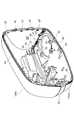
図1に示すように、車両用ドアミラー1は、フロントドアにボルト止めされるベース部2aから水平に張り出した台座部2bを有する樹脂製のドアミラーベース2と、ドアミラーベース2の台座部2bに取り付けられるドアミラー本体3とを備えている。このドアミラー本体3は、ドアミラーベース2の台座部2bにネジによって下端が固定されるシャフトと、ミラーの傾動機構などを固定すると共に、シャフトに対して回動自在な樹脂製のフレームと、フレームが固定されるカップ状の樹脂製ハウジング4と、ミラーを取り囲むように、ハウジング4の開口の周囲でハウジング4に嵌合される樹脂製のバイザー43と、を備えている。 As shown in FIG. 1, a
図2及び図3に示すように、ハウジング4は、上側に位置するアッパーハウジング10と、下側に位置するロアハウジング11とで二分割され、アッパーハウジング10とロアハウジング11との間には、サイドターンランプを構成するランプアッシー12が配置されている。 As shown in FIGS. 2 and 3, the
このように、ハウジング4が上下で二分割されることで、アッパーハウジング10とロアハウジング11との材質を異ならせたり、色を変えたりすることができ、ハウジング4の質感や外観を容易に変更することができる。しかも、ハウジング4には、ランプアッシーを挿入するために、従来のような横長なコ字状の切欠部を形成する必要が無いので、射出成形による変形や、塗装時に加わる熱変形により、ハウジング4とランプアッシー12との組み付け誤差が発生し難く、ハウジング4の表面側において、ハウジング4とランプアッシー12との間に隙間が発生し難い。そして、このようなハウジング4は、寸法チューニングの必要が生じ難い。 As described above, the
また、ランプアッシー12は、アッパーハウジング10及びロアハウジング11に固定されるレンズベース13と、このレンズベース13に溶着等で固定されたレンズ部14と、レンズベース13とレンズ部14とで形成される内部空間に配列されたLED(不図示)と、を有している。 The
さらに、ロアハウジング11の内面には、鉛直方向に突出する爪片11b,11c,11dが設けられ、ランプアッシー12の下側には、水平方向に突出する係止片12a,12b,12cが設けられている。そして、それぞれの爪片11b,11c,11dの先端部が係止片12a,12b,12cに引っ掛けられることで、ランプアッシー12は、ロアハウジング11に掛け止めされ、鉛直方向でランプアッシー12とロアハウジング11とが分離するのを防止している。 Further, claw
ロアハウジング11の内面には、三角形状のリブ11eが立設され、ランプアッシー12の下側には、鉛直方向に延在する受け面12fが形成され、リブ11eの直立面に受け面12fが当接されることで、ランプアッシー12はロアハウジング11に水平方向に押し付けられる。 A
また、アッパーハウジング10の内面には、水平方向に突出する爪片10bが設けられ、ランプアッシー12の上側には、鉛直方向に突出する係止片12dが設けられている。そして、爪片10bの先端部が係止片12dに引っ掛けられることで、ランプアッシー12は、アッパーハウジング10に掛け止めされ、ランプアッシー12がアッパーハウジング10から水平方向に抜けるのを防止している。 Further, a
さらに、ランプアッシー12の上側には、鉛直方向に突出したL字形の押え爪12eが設けられ、アッパーハウジング10の内面には、水平方向に突出した引っ掛けリブ10cが設けられている。そして、押え爪12eの先端部が引っ掛けリブ10cに引っ掛けられることで、鉛直方向でランプアッシー12とアッパーハウジング10とが分離するのを防止している。 Further, an L-shaped
また、アッパーハウジング10の内面には水平方向に突出するボス部20が設けられ、ランプアッシー12のレンズベース13の上側には、鉛直方向に延在してボス部20の遊端に当接する当接片21が設けられている。さらに、このボス部20の中央には、ネジ22が水平方向にねじ込まれるネジ螺着部が設けられ、当接片21には、ネジ22が貫通するネジ貫通孔24が形成されている。 Further, a
アッパーハウジング10には、ボス部20に隣接して水平方向に突出する位置決めピン29が設けられ、この位置決めピン29は、当接片21に形成されたピン挿入孔25内に差し込まれることで、アッパーハウジング10に対するランプアッシー12の位置決めを達成している。更に、アッパーハウジング10の表面側には、水平方向に延在してランプアッシー12のレンズ部14に突き合わされる第1の突き合わせ部26が形成されている。この第1の突き合わせ部26は、ランプアッシー12の表面側に位置して水平方向に延在する段状の第2の突き合わせ部27に当接され、この第2の突き合わせ部27には、等間隔に突起部27aが一体成形されている。 The
同様に、ロアハウジング11の内面には水平方向に突出するボス部30が設けられ、ランプアッシー12のレンズベース13の下側には、鉛直方向に延在してボス部30の遊端に当接する当接片31が設けられている。さらに、このボス部30の中央には、ネジ32が水平方向にねじ込まれるネジ螺着部が設けられ、当接片31には、ネジ32が貫通するネジ貫通孔34が形成されている。更に、ロアハウジング11の表面側には、水平方向に延在してランプアッシー12のレンズ部14に突き合わされる第1の突き合わせ部28が形成されている。この第1の突き合わせ部28は、ランプアッシー12の表面側に位置して水平方向に延在する段状の第2の突き合わせ部35に当接される。この第2の突き合わせ部35にも、突起部27aと同様の突起部(不図示)が一体成形されている。 Similarly, a
ハウジング4について更に詳細に説明する。 The
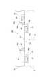
図4に示すように、アッパーハウジング10の下端には略水平方向に延在する第1の分割端面S1が形成され、ロアハウジング11の上端には略水平方向に延在する第2の分割端面S2が形成されている。そして、ハウジング4は、ランプアッシー12を露出させるように、アッパーハウジング10の第1の分割端面S1と、ロアハウジング11の第2の分割端面S1とを離間させているランプ露出部分H1と、アッパーハウジング10の第1の分割端面S1とロアハウジング11の第2の分割端面S2とを接合させている接合部分H2と、を有している。 As shown in FIG. 4, a first divided end surface S <b> 1 extending in a substantially horizontal direction is formed at the lower end of the
図5〜図7に示すように、接合部分H2には、アッパーハウジング10の内面に位置して、アッパーハウジング10の第1の分割端面S1を越えて下方に突出すると共に、ロアハウジング11の内面に引っ掛けられる第1の掛け止め片36と、ロアハウジング11の内面に位置して、ロアハウジング11の第2の分割端面S2を越えて上方に突出すると共に、アッパーハウジング10の内面に引っ掛けられる第2の掛け止め片38と、が設けられている。 As shown in FIGS. 5 to 7, the joint portion H <b> 2 is located on the inner surface of the
各々の第1の掛け止め片36は、第1の分割端面S1に沿って並設されていると共に、矩形の中空部36aを有するコ字状に形成されている。これに対して、ロアハウジング11の内面には、第1の掛け止め片36の中空部36aに引っ掛け可能な爪部37が形成され、この爪部37は、上部を頂点とした断面略直角三角形状になっているので、爪部37に第1の掛け止め片36の中空部36aを引っ掛け易く、一旦、爪部37に第1の掛け止め片36が係止させられると第1の掛け止め片36は外れ難い。 Each of the
同様に、第2の掛け止め片38は、矩形の中空部38aを有するコ字状をなしている。これに対して、アッパーハウジング10の内面には、第2の掛け止め片38の中空部38aに引っ掛け可能な爪部39が形成され、この爪部39は、下部を頂点とした断面略直角三角形状になっているので、爪部39が第2の掛け止め片38の中空部38aに引っ掛け易く、一旦爪部39に第2の掛け止め片38が係止させられると第2の掛け止め片38は外れ難い。 Similarly, the
このようにハウジング4は、アッパーハウジング10とロアハウジング11とを直接接合させる部分H2をもっているので、ハウジング4自体の剛性を高めることができる。そして、ワンタッチでアッパーハウジング10とロアハウジング11とを接合させることができ、組立作業性が向上する。 Thus, since the
アッパーハウジング10の内面には、ロアハウジング11の第2の掛け止め片38をアッパーハウジング10の第1の分割端面S1に向けて下から矢印A方向に挿入した時に、第2の掛け止め片38の先端の隅部38bが当接する位置で、上方に行くにつれて第2の掛け止め片38に近づくように傾けられたガイドリブ40が起立させられている。 On the inner surface of the
更に、ロアハウジング11の内面には、ロアハウジング11の第2の分割端面S2を越えて上方に突出する位置決め片41が形成されている。そして、アッパーハウジング10の内面には、ロアハウジング11の位置決め片41を下からアッパーハウジング10の第1の分割端面S1に向けて矢印A方向に挿入した時に、位置決め片41の先端の隅部41aが当接する位置で、上方に行くにつれて位置決め片41に近づくように傾けられたガイドリブ42が起立させられている。 Further, a
図7に示すように、アッパーハウジング10とロアハウジング11との接合に利用される第2の掛け止め片38と位置決めのみに利用される位置決め片41を、それぞれのガイドリブ40,42に突き当てされながら、アッパーハウジング10とロアハウジング11とを接合させることができるので、アッパーハウジング10に対してロアハウジング11が分割端面S1,S2の延在方向にズレることなく、アッパーハウジング10とロアハウジング11とを容易に接合させることができる。しかも、ガイドリブ40,42が傾けられているので、第2の掛け止め片38及び位置決め片41の挿入位置が分割端面S1,S2の延在方向に多少ズレたとしても、ガイドリブ40,42に、第2の掛け止め片38と位置決め片41の何れか一方又は両方を確実に当て付けることができる。 As shown in FIG. 7, the
図3、図6及び図8に示すように、ハウジング4の開口側にはバイザー43が装着され、このバイザー43の外周には、スカート状の回り縁43aが形成され、バイザー43には、回り縁43aより内側に位置するミラー収容部43dが設けられ、このミラー収容部43d内に傾動自在なミラーが収容される。そして、この回り縁43aの遊端には、上側及び下側で略水平方向に延在する凸部43bが形成され、凸部43bは、ハウジング4の開口側の端面に沿って延在する凹部44内に挿入され、これによって、ハウジング4とバイザー43の位置合わせがなされている。 As shown in FIGS. 3, 6, and 8, a
アッパーハウジング10及びロアハウジング11には、アッパーハウジング10及びロアハウジング11の内面に位置して、開口側の端面を越えて突出するテーパー形状のガイド片45が設けられている。そして、各ガイド片45は、ハウジング4の開口側にバイザー43を装着させる際に、バイザー43における回り縁43aの内面43cに摺接する。このような構成を採用すると、ハウジング4にバイザー43を組み付ける際に、ハウジング4に対してバイザー43が捻れの位置関係になることを防止し、ガイド片45に沿ってバイザー43をハウジング4に確実に組み付けることができ、組立作業性が向上する。 The
さらに、バイザー43の回り縁43aには、この遊端から突出する第3の掛け止め片46が設けられ、各々の第3の掛け止め片46は、並設されていると共に、矩形の中空部46aを有するコ字状に形成されている。これに対して、アッパーハウジング10の内面には、第3の掛け止め片46の中空部46aに引っ掛け可能な爪部47が形成され、この爪部47は、ハウジング4の開口側を頂点とした断面略直角三角形状になっているので、爪部47に第3の掛け止め片46の中空部46aを引っ掛け易く、一旦、爪部47に第3の掛け止め片46が係止させられると第3の掛け止め片46は外れ難い。 Further, a
図3に示すように、アッパーハウジング10には、ボス部50が設けられ、ランプアッシー12には、ボス部50の遊端に当接する当接片51が設けられ、バイザー43には、ネジ貫通孔52が設けられ、ボス部50と当接片51とバイザー43とは、ネジ53によって連結される。アッパーハウジング10には、ボス部60が設けられ、バイザー43には、ネジ貫通孔62が設けられ、ボス部60とバイザー43とは、ネジ63によって連結される。ロアハウジング11には、ボス部70が設けられ、ランプアッシー12には、ボス部70の遊端に当接する当接片71が設けられ、バイザー43には、ネジ貫通孔72が設けられ、ボス部70と当接片71とバイザー43とは、ネジ73によって連結される。 As shown in FIG. 3, the
本発明は、前述した実施形態に限定されないことは言うまでもない。例えば、ガイドリブ40,42は、第1の掛け止め片36の先端を案内するために、ロアハウジング11側に形成されていてもよい。 It goes without saying that the present invention is not limited to the embodiment described above. For example, the
1…ドアミラー、4…ハウジング、10…アッパーハウジング、11…ロアハウジング、12…ランプアッシー、36…第1の掛け止め片、38…第2の掛け止め片、40…ガイドリブ、43…バイザー、45…ガイド片、S1…第1の分割端面、S2…第2の分割端面、H1…ランプ露出部分、H2…接合部分。 DESCRIPTION OF
Claims (5)
Translated fromJapanese前記ハウジングは、上側に位置する樹脂製のアッパーハウジングと、下側に位置する樹脂製のロアハウジングと、に二分割され、
前記アッパーハウジングと前記ロアハウジングとの間にランプアッシーが配置され、
前記ハウジングは、
前記ランプアッシーを露出させるように、前記アッパーハウジングの下端に形成された第1の分割端面と、前記ロアハウジングの上端に形成された第2の分割端面とを離間させているランプ露出部分と、
前記アッパーハウジングの前記第1の分割端面と前記ロアハウジングの前記第2の分割端面とを接合させている接合部分と、を有し、
前記ランプ露出部分は、車両から離れる端部まで達しており、前記ランプ露出部分よりも車両側に前記接合部分が形成されていることを特徴とする車両用ドアミラー。In a vehicle door mirror having a cup-shaped housing,
The housing is divided into a resin upper housing located on the upper side and a resin lower housing located on the lower side,
A lamp assembly is disposed between the upper housing and the lower housing;
The housing is
A lamp exposed portion that separates a first divided end surface formed at the lower end of the upper housing and a second divided end surface formed at the upper end of the lower housing so as to expose the lamp assembly;
A joining portion joining the first split end face of the upper housing and the second split end face of the lower housing;
The vehicle door mirror characterized in that thelamp exposed portion reaches an end away from the vehicle, and the joint portion is formed closer to the vehicle than the lamp exposed portion .
前記ハウジングは、上側に位置する樹脂製のアッパーハウジングと、下側に位置する樹脂製のロアハウジングと、に二分割され、
前記アッパーハウジングと前記ロアハウジングとの間にランプアッシーが配置され、
前記ハウジングは、
前記ランプアッシーを露出させるように、前記アッパーハウジングの下端に形成された第1の分割端面と、前記ロアハウジングの上端に形成された第2の分割端面とを離間させているランプ露出部分と、
前記アッパーハウジングの前記第1の分割端面と前記ロアハウジングの前記第2の分割端面とを接合させている接合部分と、を有し、
前記ランプアッシーは、前記アッパーハウジング及び前記ロアハウジングに固定されていることを特徴とする車両用ドアミラー。In a vehicle door mirror having a cup-shaped housing,
The housing is divided into a resin upper housing located on the upper side and a resin lower housing located on the lower side,
A lamp assembly is disposed between the upper housing and the lower housing;
The housing is
A lamp exposed portion that separates a first divided end surface formed at the lower end of the upper housing and a second divided end surface formed at the upper end of the lower housing so as to expose the lamp assembly;
A joining portion joining the first split end face of the upper housing and the second split end face of the lower housing;
The lamp assembly isa car dual door mirroryou characterized inthat it is fixed to the upper housing and the lower housing.
前記アッパーハウジングの内面に位置して、前記アッパーハウジングの前記第1の分割端面を越えて下方に突出すると共に、前記ロアハウジングの内面に引っ掛けられる第1の掛け止め片と、
前記ロアハウジングの内面に位置して、前記ロアハウジングの前記第2の分割端面を越えて上方に突出すると共に、前記アッパーハウジングの内面に引っ掛けられる第2の掛け止め片と、が設けられていることを特徴とする請求項1又は2に記載の車両用ドアミラー。In the joint part,
A first latching piece located on the inner surface of the upper housing and projecting downward beyond the first split end surface of the upper housing and hooked on the inner surface of the lower housing;
Located on the inner surface of thelower housing, together with the projecting upwardly beyond the second split end surface of the lower housing, and a second latching piece is hooked on the inner surface of the upper housing, it is provided The door mirror for vehicles according to claim1 or 2 characterized by things.
前記アッパーハウジング及び前記ロアハウジングには、前記アッパーハウジング及び前記ロアハウジングの内面に位置して、開口側端面を越えて突出するガイド片が設けられ、前記ガイド片は前記バイザーの内面に摺接することを特徴とする請求項1〜4の何れか一項に記載の車両用ドアミラー。A visor attached to the opening side of the housing;
The upper housing and the lower housing are provided with guide pieces that are located on the inner surfaces of the upper housing and the lower housing and project beyond the end surface on the opening side, and the guide pieces are in sliding contact with the inner surface of the visor. The door mirror for vehicles as described in any one of Claims 1-4 characterized by these.
Priority Applications (4)
| Application Number | Priority Date | Filing Date | Title |
|---|---|---|---|
| JP2010040878AJP5501799B2 (en) | 2010-02-25 | 2010-02-25 | Vehicle door mirror |
| US12/938,631US8210726B2 (en) | 2010-02-25 | 2010-11-03 | Door mirror for an automobile |
| DE102010051017ADE102010051017A1 (en) | 2010-02-25 | 2010-11-11 | Door mirror for a motor vehicle |
| CN201010575577.7ACN102166986B (en) | 2010-02-25 | 2010-11-30 | Door mirror for an automobile |
Applications Claiming Priority (1)
| Application Number | Priority Date | Filing Date | Title |
|---|---|---|---|
| JP2010040878AJP5501799B2 (en) | 2010-02-25 | 2010-02-25 | Vehicle door mirror |
Publications (2)
| Publication Number | Publication Date |
|---|---|
| JP2011173572A JP2011173572A (en) | 2011-09-08 |
| JP5501799B2true JP5501799B2 (en) | 2014-05-28 |
Family
ID=44356846
Family Applications (1)
| Application Number | Title | Priority Date | Filing Date |
|---|---|---|---|
| JP2010040878AActiveJP5501799B2 (en) | 2010-02-25 | 2010-02-25 | Vehicle door mirror |
Country Status (4)
| Country | Link |
|---|---|
| US (1) | US8210726B2 (en) |
| JP (1) | JP5501799B2 (en) |
| CN (1) | CN102166986B (en) |
| DE (1) | DE102010051017A1 (en) |
Families Citing this family (11)
| Publication number | Priority date | Publication date | Assignee | Title |
|---|---|---|---|---|
| JP5389693B2 (en)* | 2010-02-25 | 2014-01-15 | 株式会社村上開明堂 | Vehicle door mirror |
| JP6408196B2 (en)* | 2012-10-01 | 2018-10-17 | 株式会社石▲崎▼本店 | Housing structure for vehicle door mirrors |
| JP5784574B2 (en)* | 2012-11-08 | 2015-09-24 | 株式会社東海理化電機製作所 | Mirror device for vehicle |
| JP5995103B2 (en)* | 2013-10-30 | 2016-09-21 | 株式会社ホンダロック | Vehicle door mirror |
| US10259391B2 (en) | 2014-10-16 | 2019-04-16 | Honda Motor Co., Ltd. | Side mirror device |
| JP6159699B2 (en)* | 2014-10-16 | 2017-07-05 | 本田技研工業株式会社 | Side mirror device |
| DE102015108486A1 (en)* | 2015-05-29 | 2016-12-01 | Hella Kgaa Hueck & Co. | Side indicator for vehicles |
| JP6625487B2 (en)* | 2016-06-10 | 2019-12-25 | 株式会社東海理化電機製作所 | Door mirror device and method of manufacturing door mirror device |
| JP2017218130A (en) | 2016-06-10 | 2017-12-14 | 株式会社東海理化電機製作所 | Door mirror device |
| FR3095851B1 (en)* | 2019-05-07 | 2021-04-16 | Psa Automobiles Sa | Signaling module box for motor vehicles and vehicle equipped with said module |
| US20210031689A1 (en) | 2019-07-31 | 2021-02-04 | Ficosa North America Corporation | Exterior rearview mirror or winglet for a vehicle having a lighting lens assembly attached to a housing |
Family Cites Families (21)
| Publication number | Priority date | Publication date | Assignee | Title |
|---|---|---|---|---|
| GB8401920D0 (en)* | 1984-01-25 | 1984-02-29 | Winstanley J | Rear view mirror |
| US4812955A (en)* | 1988-04-12 | 1989-03-14 | Truck-Lite Co., Inc. | Modular shock resistant/sealed multi-function lamp |
| JPH0727260Y2 (en)* | 1989-12-08 | 1995-06-21 | 泉自動車株式会社 | Steering column cover |
| CN2294189Y (en)* | 1997-03-24 | 1998-10-14 | 谢基生 | Movable vehicle monitor with side lights and surveillance effects |
| CA2230930A1 (en)* | 1997-04-25 | 1998-10-25 | Dale Gathergood | Exterior rear view mirror integral warning light |
| US6039448A (en)* | 1998-10-01 | 2000-03-21 | Oprea; Florin I. | Side rearview mirror device |
| US6142656A (en)* | 1999-03-26 | 2000-11-07 | Kurth; John F. | Multi-functional side rear view mirror for a vehicle |
| US6511192B1 (en)* | 1999-12-17 | 2003-01-28 | Britax Vision Systems (North America) Inc. | Side view mirror with integral lighting |
| US7008089B1 (en)* | 2000-02-01 | 2006-03-07 | Schefenacker Vision Systems Usa Inc. | Exterior rear view mirror having a chin strap and a repeater |
| ES2168071B1 (en)* | 2000-07-12 | 2003-07-16 | Barros Alejandro Rodriguez | MODULAR REAR VIEW MIRROR WITH INTERCHANGEABLE MULTIPLE SIGNALS FOR VEHICLES OF 2, 3, 4 OR MORE WHEELS. |
| JP4038975B2 (en) | 2000-09-21 | 2008-01-30 | 市光工業株式会社 | Vehicle door mirror |
| JP3977585B2 (en)* | 2000-10-06 | 2007-09-19 | 株式会社ケーヒン | Substrate storage case |
| US6811288B2 (en)* | 2001-06-29 | 2004-11-02 | Donnelly Corporation | Sideview mirror assembly with utility features |
| JP3500612B2 (en)* | 2002-02-20 | 2004-02-23 | 本田技研工業株式会社 | Light emitting circuit and lighting device |
| JP4109982B2 (en)* | 2002-12-24 | 2008-07-02 | 株式会社東海理化電機製作所 | Assembly structure of vehicle mirror device |
| JP4468662B2 (en)* | 2003-07-30 | 2010-05-26 | サカエ理研工業株式会社 | Door mirror device with turn signal lamp |
| JP4961171B2 (en)* | 2006-06-22 | 2012-06-27 | 株式会社ミツバ | Vehicle door mirror |
| JP5115053B2 (en)* | 2007-06-25 | 2013-01-09 | 市光工業株式会社 | Vehicle side mirror |
| JP4599377B2 (en)* | 2007-08-21 | 2010-12-15 | 株式会社村上開明堂 | Outer mirror |
| JP2010040878A (en) | 2008-08-06 | 2010-02-18 | Toshiba Lighting & Technology Corp | Lighting device for light-emitting diode |
| JP2010269705A (en)* | 2009-05-21 | 2010-12-02 | Murakami Corp | Shaft structure of retractable outer mirror |
- 2010
- 2010-02-25JPJP2010040878Apatent/JP5501799B2/enactiveActive
- 2010-11-03USUS12/938,631patent/US8210726B2/ennot_activeExpired - Fee Related
- 2010-11-11DEDE102010051017Apatent/DE102010051017A1/ennot_activeCeased
- 2010-11-30CNCN201010575577.7Apatent/CN102166986B/enactiveActive
Also Published As
| Publication number | Publication date |
|---|---|
| JP2011173572A (en) | 2011-09-08 |
| CN102166986B (en) | 2015-02-18 |
| US8210726B2 (en) | 2012-07-03 |
| CN102166986A (en) | 2011-08-31 |
| DE102010051017A1 (en) | 2011-08-25 |
| US20110205747A1 (en) | 2011-08-25 |
Similar Documents
| Publication | Publication Date | Title |
|---|---|---|
| JP5501799B2 (en) | Vehicle door mirror | |
| JP5411021B2 (en) | Door mirror housing structure | |
| JP6348930B2 (en) | Body structure | |
| JP4951280B2 (en) | Mirror base | |
| JP2008012953A (en) | Interior part for automobile | |
| JP2011173557A (en) | Door mirror for vehicle | |
| JP6012300B2 (en) | Mirror base structure | |
| JP4722611B2 (en) | Fender cover structure | |
| WO2018174230A1 (en) | Coupling structure for wiper blade and wiper arm, and wiper blade | |
| JP4970341B2 (en) | Two-part assembly structure | |
| JP2008022595A (en) | Protector | |
| JP4622528B2 (en) | Front fender mounting structure of cover member | |
| JP2018078051A (en) | connector | |
| JP2012235575A (en) | Protector | |
| JP2008083562A (en) | Display device | |
| JP2004111318A (en) | Connector | |
| JP6140832B2 (en) | Body bumper structure | |
| JP3949881B2 (en) | Corner piece mounting structure for automobile doors | |
| JP4811219B2 (en) | Shift lever device peripheral structure | |
| KR101987876B1 (en) | Mounting clip assembly for trim | |
| JP2020205209A (en) | Connector stay and door mirror structure | |
| JP2015231784A (en) | Package tray, pillar garnish and assembling structure of package tray | |
| JP4622529B2 (en) | Roof molding mounting structure | |
| JP6367898B2 (en) | Mirror device for vehicle | |
| JP2004216948A (en) | Rearview mirror for vehicles |
Legal Events
| Date | Code | Title | Description |
|---|---|---|---|
| A621 | Written request for application examination | Free format text:JAPANESE INTERMEDIATE CODE: A621 Effective date:20120622 | |
| A977 | Report on retrieval | Free format text:JAPANESE INTERMEDIATE CODE: A971007 Effective date:20130808 | |
| A131 | Notification of reasons for refusal | Free format text:JAPANESE INTERMEDIATE CODE: A131 Effective date:20130820 | |
| A521 | Request for written amendment filed | Free format text:JAPANESE INTERMEDIATE CODE: A523 Effective date:20131017 | |
| TRDD | Decision of grant or rejection written | ||
| A01 | Written decision to grant a patent or to grant a registration (utility model) | Free format text:JAPANESE INTERMEDIATE CODE: A01 Effective date:20140304 | |
| A61 | First payment of annual fees (during grant procedure) | Free format text:JAPANESE INTERMEDIATE CODE: A61 Effective date:20140312 | |
| R150 | Certificate of patent or registration of utility model | Ref document number:5501799 Country of ref document:JP Free format text:JAPANESE INTERMEDIATE CODE: R150 | |
| R250 | Receipt of annual fees | Free format text:JAPANESE INTERMEDIATE CODE: R250 | |
| R250 | Receipt of annual fees | Free format text:JAPANESE INTERMEDIATE CODE: R250 | |
| R250 | Receipt of annual fees | Free format text:JAPANESE INTERMEDIATE CODE: R250 | |
| R250 | Receipt of annual fees | Free format text:JAPANESE INTERMEDIATE CODE: R250 | |
| R250 | Receipt of annual fees | Free format text:JAPANESE INTERMEDIATE CODE: R250 | |
| R250 | Receipt of annual fees | Free format text:JAPANESE INTERMEDIATE CODE: R250 | |
| R250 | Receipt of annual fees | Free format text:JAPANESE INTERMEDIATE CODE: R250 | |
| R250 | Receipt of annual fees | Free format text:JAPANESE INTERMEDIATE CODE: R250 | |
| R250 | Receipt of annual fees | Free format text:JAPANESE INTERMEDIATE CODE: R250 |