JP5500055B2 - Portable cutting machine - Google Patents
Portable cutting machineDownload PDFInfo
- Publication number
- JP5500055B2 JP5500055B2JP2010270320AJP2010270320AJP5500055B2JP 5500055 B2JP5500055 B2JP 5500055B2JP 2010270320 AJP2010270320 AJP 2010270320AJP 2010270320 AJP2010270320 AJP 2010270320AJP 5500055 B2JP5500055 B2JP 5500055B2
- Authority
- JP
- Japan
- Prior art keywords
- saw blade
- wall
- dust collection
- collection box
- blade
- Prior art date
- Legal status (The legal status is an assumption and is not a legal conclusion. Google has not performed a legal analysis and makes no representation as to the accuracy of the status listed.)
- Active
Links
- 238000005520cutting processMethods0.000titleclaimsdescription58
- 239000000428dustSubstances0.000claimsdescription60
- 230000002093peripheral effectEffects0.000claimsdescription16
- 230000001012protectorEffects0.000claimsdescription16
- 239000011521glassSubstances0.000claimsdescription14
- 229910052751metalInorganic materials0.000claimsdescription10
- 239000002184metalSubstances0.000claimsdescription10
- 229920003002synthetic resinPolymers0.000claimsdescription6
- 239000000057synthetic resinSubstances0.000claimsdescription6
- 238000012544monitoring processMethods0.000claims2
- 244000144985peepSpecies0.000claims1
- XEEYBQQBJWHFJM-UHFFFAOYSA-NIronChemical compound[Fe]XEEYBQQBJWHFJM-UHFFFAOYSA-N0.000description2
- 238000007689inspectionMethods0.000description2
- 229910052782aluminiumInorganic materials0.000description1
- XAGFODPZIPBFFR-UHFFFAOYSA-NaluminiumChemical compound[Al]XAGFODPZIPBFFR-UHFFFAOYSA-N0.000description1
- 229910052742ironInorganic materials0.000description1
- 230000000149penetrating effectEffects0.000description1
- 229920000515polycarbonatePolymers0.000description1
- 239000004417polycarbonateSubstances0.000description1
- 230000000007visual effectEffects0.000description1
Images


Landscapes
- Sawing (AREA)
Description
Translated fromJapanese本発明は携帯用切断機に関する。 The present invention relates to a portable cutting machine.
一般に、回転するチップソーで部材を切断する携帯用切断機は、木板のほかに鉄、アルミなどの金属製部材を切断することができる。これらの金属製部材を切断する際には切粉が飛散するので、のこ刃を回転自在に設けた定盤(ベース)の上部には飛散した切粉を集めるための集塵ボックスが設けられている。集塵ボックスは、のこ刃の上方を覆うように配置されているので、のこ刃よりも大きく、定盤と密接するように配置されている。 Generally, a portable cutting machine that cuts a member with a rotating tip saw can cut a metal member such as iron or aluminum in addition to a wooden board. When cutting these metal parts, chips are scattered, so a dust collection box for collecting the scattered chips is provided on the top of the surface plate (base) provided with a saw blade. ing. Since the dust collection box is disposed so as to cover the upper side of the saw blade, it is larger than the saw blade and disposed so as to be in close contact with the surface plate.
部材を切断するときは、部材を定盤の下面にあてがうが、のこ刃がどこにあるのかがわからないと切断位置を特定することができない。そこで、集塵ボックスを透明な合成樹脂から構成し、集塵ボックスからのこ刃の先端を透視して切断位置の狙いが定められるようになっている(特許文献1参照)。さらに、定盤にも、のこ刃の中心の延長上で集塵ボックスに覆われない位置にのぞき窓を開口形成し、真上からのぞき窓越しに刃先と部材に設けられた切断用マークとを合せられるようになっている。 When cutting a member, the member is applied to the lower surface of the surface plate, but the cutting position cannot be specified unless the location of the saw blade is known. Therefore, the dust collection box is made of a transparent synthetic resin, and the cutting position is aimed by seeing through the tip of the saw blade from the dust collection box (see Patent Document 1). Furthermore, on the surface plate, an inspection window is formed at a position that is not covered by the dust collection box on the extension of the center of the saw blade, and a cutting mark provided on the blade edge and the member through the observation window from above. Can be matched.
しかしながら、切粉は金属で、熱くなっているから、切断時に定盤の上方に飛び散って合成樹脂製集塵ボックスの内面に衝突するので、切断作業を繰り返すうちに、内面を少しずつ傷つけていく。特に集塵ボックスの内周面には切粉が直接に当たる。このため、集塵ボックスの内周面が徐々に削られてついには外周面にまで達して周壁の端部に削りによる溝ができる。同時に、内面にできた小さな傷のために曇りが発生し、表面が白濁して透明性が損なわれ、のこ刃の視認性も失われていく。このため、作業者はのぞき窓から切断位置を確認することになるが、従来ののぞき窓はのこ刃の刃先から遠い位置に設けられているので、被切断部材の切断部分がのこ刃に近づくと、のこ刃が見えにくく、狙いが狂いやすいという問題があった。 However, since the chips are metal and are hot, they scatter over the surface of the platen and collide with the inner surface of the dust collection box made of synthetic resin. As the cutting operation is repeated, the inner surface is gradually damaged. . In particular, chips hit the inner peripheral surface of the dust collection box directly. For this reason, the inner peripheral surface of the dust collection box is gradually scraped, and finally reaches the outer peripheral surface to form a groove by shaving at the end of the peripheral wall. At the same time, clouding occurs due to small scratches on the inner surface, the surface becomes clouded and the transparency is lost, and the visibility of the saw blade is lost. For this reason, the operator checks the cutting position from the observation window, but since the conventional inspection window is provided at a position far from the blade edge of the saw blade, the cutting portion of the member to be cut becomes the saw blade. When approaching, there was a problem that the saw blade was difficult to see and the aim was likely to go wrong.
本発明は、上記問題点を解消し、集塵ボックスの透明性を維持し、長期間視認性を確保することができるとともに、耐久性を向上させることができ、また集塵ボックスに曇りが発生した際にも、のこ刃に近い位置ののぞき窓より、のこ刃の情報をわかりやすくすることができる携帯用切断機を提供することをその課題とする。 The present invention solves the above problems, maintains the transparency of the dust collection box, can ensure visibility for a long time, and can improve durability, and clouding occurs in the dust collection box. In this case, it is an object of the present invention to provide a portable cutting machine that can make the information on the saw blade easier to understand from the observation window located near the saw blade.
前記第1の課題を解決するため、請求項1に係る発明は、切断用ののこ刃を通す開口部を貫通形成した定盤の上部に、切断時に飛散した切粉を集めるための透明な合成樹脂製集塵ボックスを上記のこ刃の周囲を覆うように設けた携帯用切断機において、上記集塵ボックスは、半円弧状の周壁部と略半円形の内側壁部と外側壁部とによって構成され、上記周壁部の内周壁側と、上記内側壁部及び上記外側壁部と、に沿って金属製のプロテクタを取り付け、上記プロテクタを、透明な上記内側壁部側から上記のこ刃の刃先を透視するのに邪魔にならない位置に設け、上記集塵ボックスの内側壁部から上記のこ刃の刃先を透視可能としたことを特徴とする。In order to solve the first problem, the invention according to
請求項2に係る発明は、請求項1において、上記のこ刃の刃先を透視可能な内側壁部を外側に膨出させ、のこ刃を通す上記開口部を外側に拡開させて形成したことを特徴とする。 According to a second aspect of the present invention, in the first aspect, the inner wall portion through which the blade edge of the saw blade can be seen is bulged outward, and the opening through which the saw blade is passed is expanded outward. It is characterized by that.
請求項3に係る発明は、請求項1又は2において、上記集塵ボックスの内側壁部の内側に、硬質ガラスを接着したこと、または、上記集塵ボックスの内側壁部に開口部を形成し、この開口部に硬質ガラスを固着したことを特徴とする。 The invention according to
請求項4に係る発明は、請求項1において、上記定盤には、集塵ボックスに覆われない位置で上記のこ刃の中心の延長上には、上記のこ刃の刃先に近い位置と遠い位置とにそれぞれ第1ののぞき窓と第2ののぞき窓とを開口形成し、第1ののぞき窓の開口形成された底角を結ぶ線と第2ののぞき窓の開口形成された前後の対角を結ぶ線とが上記のこ刃の延長上にあることを特徴とする。 According to a fourth aspect of the present invention, in the first aspect, the surface plate includes a position near the blade edge of the saw blade on an extension of the center of the saw blade at a position not covered by the dust collection box. A first observation window and a second observation window are formed at distant positions, respectively, and a line connecting a bottom angle of the first observation window and a second observation window before and after the second observation window is formed. The line connecting the diagonals is on the extension of the saw blade.
請求項5に係る発明は、請求項4において、上記集塵ボックスの外側壁部の前側を絞り込んでくさび状にしたことを特徴とする。 The invention according to
請求項1に係る発明によれば、被切断部材を切断するにあたっては、のこ刃の先端がどこにあるかを確認しなければならないが、集塵ボックス内側壁部は透明であり、内側壁側のプロテクタは、集塵ボックスの内側壁部からのこ刃の刃先を透視するのに邪魔にならない位置に設けられているから、作業者は集塵ボックスの内側壁からのこ刃の刃先を透視することができる。したがって、刃先と被切断部材との位置関係を確実に把握して正確に切断することができる。 According to the first aspect of the invention, when cutting the member to be cut, it is necessary to confirm where the tip of the saw blade is located, but the inner wall portion of the dust collection box is transparent and the inner wall side Since the protector is provided at a position that does not obstruct the saw blade edge from the inner wall of the dust collection box, the operator sees the blade edge of the saw blade from the inner wall of the dust collection box. can do. Therefore, the positional relationship between the blade edge and the member to be cut can be reliably grasped and cut accurately.
また、集塵ボックスの内側壁部において、のこ刃を透視できる部位は、切粉が直接に当たりにくい部位であるから、集塵ボックスの透明性は長く維持され、長期間視認性を確保することができる。 In addition, the part that can see through the saw blade on the inner wall of the dust collection box is a part that is difficult for chips to hit directly. Therefore, the transparency of the dust collection box is maintained for a long time and visibility is ensured for a long time. Can do.
さらに、集塵ボックスの内周壁とその近傍には、切断時に飛び散った切粉が直接に当たるが、ここには金属製のプロテクタ、が取り付けられ、切粉で特に削れ易い部分がプロテクタによって良好に保護されるから、集塵ボックスの耐久性が向上する。 In addition, chips scattered during cutting directly hit the inner peripheral wall of the dust collection box and its vicinity, but a metal protector is attached here, and the parts that are particularly easily scraped by the chips are well protected by the protector. Therefore, the durability of the dust collection box is improved.
請求項2に係る発明によれば、のこ刃の刃先を透視可能な内側壁部の一部を、外側に膨出させるとともに、のこ刃を通す開口部を外側に拡開形成したので、視認領域が増大し、のこ刃の位置をより広い範囲で認識することができる。 According to the invention of
そして、この場合、外側に膨出させた分だけ集塵カバーの内側壁には切粉が接触しにくくなるので、内側壁部が白濁しにくく、視認性がより良好に持続する。 In this case, the chips are less likely to come into contact with the inner wall of the dust collection cover by the amount bulged outwardly, so that the inner wall is less likely to become cloudy and the visibility is maintained more favorably.
請求項3に係る発明によれば、上記集塵ボックスの内側壁部の内側に硬質ガラスを接着した、または、上記集塵ボックスの内側壁部に開口部を形成し、この開口部に硬質ガラスを固着したので、硬質ガラスは硬く表面に傷がつきにくいから、長期間にわたり透明度を維持することができる。 According to the invention which concerns on
請求項4に係る発明によれば、切断時に発生した切粉はプロテクタで覆った部分だけでなく、それ以外の部分にも飛び散るから、切断作業が繰り返されると、のこ刃の先端を透視する内側壁部も徐々に白濁し、ついにはのこ刃の先端が見えなくなる。このような状態になったときでも、のこ刃の先端位置を第1ののぞき窓と第2ののぞき窓から確認しながら正確に切断することができる。 According to the fourth aspect of the invention, the chips generated at the time of cutting are scattered not only in the part covered with the protector but also in other parts, so when the cutting operation is repeated, the tip of the saw blade is seen through. The inner wall also gradually becomes cloudy and eventually the tip of the saw blade disappears. Even in such a state, cutting can be accurately performed while confirming the tip position of the saw blade from the first and second observation windows.
請求項5に係る発明によれば、集塵ボックスの外側壁部の前側を絞り込んでくさび状の形状にしたので、集塵ボックスは前方が先細となり、作業者が上からのぞいたときに、特に第1ののぞき窓からのこ刃の先端位置が見やすくなる。 According to the invention according to
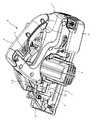
図1〜図9において符号Aは携帯用切断機を示す。この切断機Aは、切断機本体1を定盤2に回動自在に設けたもので、定盤2の一側には、切断機本体1に設けられたのこ刃(丸鋸)3を通す開口部4が貫通形成され、のこ刃3の一部は定盤2の下方に突出可能に構成されている。 1-9, the code | symbol A shows a portable cutting machine. In this cutting machine A, a cutting machine
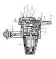
切断機本体1には、切断用ののこ刃3とのこ刃3を回転させる回転駆動機構と操作用ハンドル5とが設けられている。回転駆動機構には、図7に示されるように、のこ刃3の回転軸7と減速歯車9を介して作動連結する電動モータ6と、電動モータ6に電力を供給するバッテリパック21とが含まれる。電動モータ6はモータハウジングの内部に配置されている。操作用ハンドル5には電動モータの作動を制御するトリガ8が取り付けられている。 The cutting machine
定盤2は切断機本体1の下部に配置された金属製の板状部材で、のこ刃3を通す開口部4の下方にはのこ刃3の一部が露出し、円弧状のロアガード10によって覆われている。このロアガード10はのこ刃3の回転軸7を中心に後方から上方に回動可能に装着されている。また、定盤2の上部には、切断時に飛散した切粉を集めるための透明なポリカーボネート等の合成樹脂製集塵ボックス11が上記のこ刃3の周囲を覆うように設けられている。なお、集塵ボックス11は、図7に示されるように、半円弧状の周壁部11aと略半円形の内側壁部11bと外側壁部11cとによって構成され、内側壁部11bは切断機本体1と一体的に配設され、また周壁部11aと外側壁部11cとは一体になって、内側壁部11bに対して着脱できるように構成されている。また、外側壁部11cの前側は図6に示すように一重だが、中心側は内壁部12と外壁部13の二重構造になっており、外側壁部11cはのこ刃3をはさんで内側壁部11bに対向し、内壁部12と外壁部13との間には切粉収容部14が形成されている。内壁部12には穴15が形成され、切断によって生じた切粉は、図8に示すように穴15から切粉収容部14に飛び込んで切粉が溜まるように形成されている。なお、集塵ボックス11はのこ刃3の上部を保護するアッパーガードを兼ねている。 The
次に、集塵ボックス11は透明であるから、内側壁部11bから定盤2の開口部4を通してのこ刃3の前側先端部を透視することができる。なお、開口部4の全体は図11に示したとおりである。 Next, since the
ところで、切断時に形成された切粉は定盤2の開口部4から上方に飛び散り、集塵ボックス11の内面に衝突するが、その際、直接に当たるのは、のこ刃3の刃先の接線方向である。そこで、集塵ボックス11の内周壁20とその近傍の切粉が直接に当たる位置には金属製のプロテクタ16、17が取り付けられている。 By the way, the chips formed at the time of cutting scatter upward from the
特に、内側壁部11b側のプロテクタ17は、集塵ボックス11の内側壁部11b側からのこ刃3の刃先を透視するのに邪魔にならない位置に設けられている。 In particular, the
次に、定盤2には、集塵ボックス11に覆われない位置で、のこ刃3の延長上に、のこ刃3の刃先に近い位置と遠い位置とにそれぞれ第1ののぞき窓18と第2ののぞき窓19とが開口形成されている。第1ののぞき窓18は二等辺三角形に、また第2ののぞき窓19は菱形に形成され、のこ刃3の延長は第1ののぞき窓18の底角を結ぶ線と第2ののぞき窓19の前後の対角を結ぶ線P(図5参照)上にあるように形成されている。 Next, on the
上記切断機によって被切断部材を切断するときは、被切断部材の表面に定盤2の下面を当て、トリガ8を引き操作し、電動モータ2を作動させ、ハンドル5を押しつつ定盤2を被切断部材の表面に沿って移動させればよい。 When the member to be cut is cut by the cutting machine, the lower surface of the
被切断部材を切断するにあたっては、のこ刃3の先端がどこにあるかを確認しなければならない。これに対応し、集塵ボックス11の内側壁部11bは透明であり、内側壁側のプロテクタ16、17は、集塵ボックス11の内側壁部11b側からのこ刃3の刃先を透視するのに邪魔にならない位置に設けられているから、図1及び図2に示されるように、作業者は集塵ボックス11の内側壁からのこ刃3の刃先を透視することができる。したがって、刃先と被切断部材との位置関係を確実に把握して正確に切断することができる。 When cutting the member to be cut, it is necessary to confirm where the tip of the
また、集塵ボックス11の内側壁部11bで、のこ刃3を透視できる部位は、切粉が直接に当たりにくい部位であるから、集塵ボックス11の透明性は長く維持され、長期間視認性を確保することができる。 Moreover, since the site | part which can see through the
さらに、集塵ボックス11の内周壁20とその近傍には、切断時に飛び散った切粉が直接に当たるが、ここには金属製のプロテクタ16、17が取り付けられ、切粉で特に削れ易い部分がプロテクタ16、17によって良好に保護されるから、集塵ボックス11の耐久性が向上する。 Further, the dust scattered at the time of cutting directly hits the inner
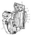
なお、図10に示されるように、のこ刃3の刃先を透視可能な内側壁部11bの一部を、外側に膨出させるとともに、のこ刃3を通す開口部4を外側に拡開形成するようにしてもよい。これによれば、視認領域が増大するので、のこ刃3の位置をより広い範囲で認識することができる。 As shown in FIG. 10, a part of the
そして、この場合、外側に膨出させた分だけ集塵カバー11の内側壁には切粉が接触しにくくなるので、内側壁部11bが白濁しにくく、視認性がより良好に持続する。 In this case, the chips are less likely to come into contact with the inner wall of the
なお、のこ刃3の刃先を透視可能な内側壁部11bの一部又は定規2ののこ刃3を通す開口部4の近傍には、合成樹脂ではなく硬質ガラス22(図1、図2、図6、図10参照)を使用してもよい。これによれば、硬質ガラスは硬く表面に傷がつきにくいので、長期間にわたり透明度を維持することができる。特に、膨出した部分に硬質ガラスを取り付けることにより、透明度が維持される期間をさらに長くすることができる。硬質ガラスは内側壁部11bの内側に接着してもよく、あるいは内側壁部11bに開口部を形成し、開口部に硬質ガラスを固着するようにしてもよい。 It should be noted that a portion of the
同様に、プロテクタ16、17は金属であるから、のこ刃3の刃先を透視することはできないが、その取付け領域は内周壁20とその近傍にのみ限定されるものではない。のこ刃3の刃先を透視する際の障害とならない限り、他の部分に延設させてもよい。 Similarly, since the
次に、切断による切粉はプロテクタ16、17で覆った部分だけでなく、それ以外の部分にも飛び散るから、切断作業が繰り返されると、のこ刃3の先端を透視する内側壁部11bも徐々に白濁し、ついにはのこ刃3の先端が見えなくなる。このような状態になったときでも、のこ刃3の先端の直近に第1ののぞき窓18を設け、さらにその延長線上に第2ののぞき窓19を設けることで、のこ刃3の切断方向の情報を確認することができる。通常の場合、作業者は、被切断部材の表面に切断用のマークとして墨線を施しておき、定盤2の前部を被切断部材の上に置く。このとき、のこ刃3を被切断部材から少し離すので、墨線は第2ののぞき窓19から確認する。そして、のこ刃3の回転速度を最大にしてから、のこ刃3を被切断部材に近づけ、第1ののぞき窓18から切断位置を確認しながら切断を開始する。 Next, since the chips by cutting scatter not only in the parts covered by the
なお、被切断部材に墨線を施さないときは、第1ののぞき窓18と第2ののぞき窓19から直接にのこ刃3の先端を直接に見て切断すべき部位に正確に狙いを合せて切断すればよい。このように、集塵ボックス11が白濁しても、第1又は第2ののぞき窓18又は19からのこ刃3の切断方向の情報を確認することができる。 When the black line is not applied to the member to be cut, the aim is precisely aimed at the portion to be cut by directly looking at the tip of the
ところで、第1ののぞき窓18は、なるべくのこ刃3の先端に近い位置に配置するのが好ましい。近ければ近いほどよいが、開口部4から連続して延長形成すると、この部分の強度に影響が出るので、開口部4の前端部から1mm以上の位置に形成するのが好ましい。1mm以下では強度上問題が発生する。また、10mm以上になると、第1のぞき窓は定盤2の開口部4からのこ刃3の先端が見えにくくなる。 By the way, it is preferable to arrange | position the
なお、のぞき窓は3個以上あってもよい。 There may be three or more viewing windows.
なお、のこ刃3の位置を容易に確認するためには、なるべく集塵ボックス11の形状を薄くするのが好ましい。特に、図3に示されるように、集塵ボックス11の外側壁部11cの前側形状を内側に絞り込んでくさび状の形状とするのがよい。これによれば、集塵ボックス11は前方が先細となるので、作業者が上からのぞいたときに、特に第1ののぞき窓18からのこ刃3の先端が見やすくなる。 In addition, in order to confirm the position of the
1 切断機本体
2 定盤
3 のこ刃
4 開口部
6 定盤2
11 集塵ボックス
11b 内側壁部
11c 外側壁部
16、17 プロテクタ1 Cutting
11
Claims (5)
Translated fromJapanesePriority Applications (2)
| Application Number | Priority Date | Filing Date | Title |
|---|---|---|---|
| JP2010270320AJP5500055B2 (en) | 2010-12-03 | 2010-12-03 | Portable cutting machine |
| CN201110399471.0ACN102528854B (en) | 2010-12-03 | 2011-12-05 | Portable cutting machine |
Applications Claiming Priority (1)
| Application Number | Priority Date | Filing Date | Title |
|---|---|---|---|
| JP2010270320AJP5500055B2 (en) | 2010-12-03 | 2010-12-03 | Portable cutting machine |
Publications (2)
| Publication Number | Publication Date |
|---|---|
| JP2012115969A JP2012115969A (en) | 2012-06-21 |
| JP5500055B2true JP5500055B2 (en) | 2014-05-21 |
Family
ID=46337507
Family Applications (1)
| Application Number | Title | Priority Date | Filing Date |
|---|---|---|---|
| JP2010270320AActiveJP5500055B2 (en) | 2010-12-03 | 2010-12-03 | Portable cutting machine |
Country Status (2)
| Country | Link |
|---|---|
| JP (1) | JP5500055B2 (en) |
| CN (1) | CN102528854B (en) |
Families Citing this family (6)
| Publication number | Priority date | Publication date | Assignee | Title |
|---|---|---|---|---|
| CN103506690B (en)* | 2012-06-29 | 2017-08-29 | 博世电动工具(中国)有限公司 | Annular saw with chip barrier element |
| CN103537752B (en)* | 2012-07-13 | 2016-10-05 | 苏州宝时得电动工具有限公司 | Portable cutter |
| CN106378491A (en) | 2012-07-13 | 2017-02-08 | 苏州宝时得电动工具有限公司 | Portable cutting machine |
| JP6380931B2 (en)* | 2014-09-12 | 2018-08-29 | パナソニックIpマネジメント株式会社 | Electric circular saw |
| CN110114178B (en)* | 2016-12-28 | 2021-07-09 | 工机控股株式会社 | Portable Cutter |
| JP7468154B2 (en)* | 2020-05-29 | 2024-04-16 | 工機ホールディングス株式会社 | Work Machine |
Family Cites Families (16)
| Publication number | Priority date | Publication date | Assignee | Title |
|---|---|---|---|---|
| JPS61172703A (en)* | 1985-01-28 | 1986-08-04 | 日立工機株式会社 | Dust collector for portable electric tool |
| JPS62167002A (en)* | 1986-01-17 | 1987-07-23 | 日立工機株式会社 | Portable rotary cutting machine blade cover |
| JPS62144606U (en)* | 1986-03-07 | 1987-09-11 | ||
| JPS6342801A (en)* | 1986-08-08 | 1988-02-24 | 日立工機株式会社 | Portable dust collection circular saw |
| JPH06278101A (en)* | 1993-03-26 | 1994-10-04 | Matsushita Electric Works Ltd | Electric circular saw |
| JP3214295B2 (en)* | 1995-05-12 | 2001-10-02 | 日立工機株式会社 | Portable dust collection circular saw |
| JP3802620B2 (en)* | 1996-09-03 | 2006-07-26 | 新ダイワ工業株式会社 | Dust collecting mechanism of portable circular saw device |
| JPH10113905A (en)* | 1996-10-11 | 1998-05-06 | Ryobi Ltd | Cutter |
| JPH10202609A (en)* | 1997-01-28 | 1998-08-04 | Matsushita Electric Works Ltd | Circular saw |
| JP3661465B2 (en)* | 1999-01-08 | 2005-06-15 | 日立工機株式会社 | Metal cutting machine |
| JP2001062803A (en)* | 1999-08-27 | 2001-03-13 | Makita Corp | Circular saw |
| JP2002240004A (en)* | 2001-02-16 | 2002-08-28 | Ryobi Ltd | Dust collecting unit of circular saw |
| US6543143B2 (en)* | 2001-04-06 | 2003-04-08 | Black & Decker Inc. | Metal cutting circular saw with integral sight window |
| US7526866B2 (en)* | 2003-10-31 | 2009-05-05 | Black & Decker Inc. | Variable dust chute for circular saws |
| JP4466771B2 (en)* | 2008-07-07 | 2010-05-26 | パナソニック電工株式会社 | Electric circular saw |
| JP5412089B2 (en)* | 2008-11-11 | 2014-02-12 | 株式会社マキタ | Cutting machine |
- 2010
- 2010-12-03JPJP2010270320Apatent/JP5500055B2/enactiveActive
- 2011
- 2011-12-05CNCN201110399471.0Apatent/CN102528854B/ennot_activeExpired - Fee Related
Also Published As
| Publication number | Publication date |
|---|---|
| CN102528854A (en) | 2012-07-04 |
| CN102528854B (en) | 2016-02-24 |
| JP2012115969A (en) | 2012-06-21 |
Similar Documents
| Publication | Publication Date | Title |
|---|---|---|
| JP5500055B2 (en) | Portable cutting machine | |
| TW570855B (en) | Circular saw | |
| JP5093464B2 (en) | Portable cutting machine | |
| EP2039454A3 (en) | Cutting angle indicator in jigsaw housing with dust extraction | |
| CN101623874A (en) | Electric saw | |
| EP4324583A2 (en) | Compact multi-material cut-off tool | |
| US4741105A (en) | Combined envelope opener and pencil sharpener unit | |
| JP2007038645A (en) | Dust collecting cover and cutter provided with the same | |
| JP5162262B2 (en) | Protective cover and electric tool with protective cover | |
| EP2039453A3 (en) | Housing of a cutting tool including blade storage, integral blade guard and motor ventilation pathway | |
| CA3104419A1 (en) | Circular saw | |
| CN102343580B (en) | Annular saw | |
| JP4957228B2 (en) | cutter | |
| EP2886233A1 (en) | Power circular saw | |
| EP2953773B1 (en) | Circular saw blade guard with scratch-resistant panel | |
| JP5092567B2 (en) | Portable tools | |
| CN205888243U (en) | Annular saw cutting machine | |
| WO2011086736A1 (en) | Cutting machine | |
| KR920006075A (en) | Blade grinder | |
| JP2008114359A (en) | Portable belt polishing machine | |
| JPH05318403A (en) | Motor-driven circular saw | |
| JP3731856B2 (en) | Portable circular saw | |
| EP2995408A1 (en) | Power circular saw | |
| JP3144741U (en) | Protective cover for brush cutter and brush cutter provided with the same | |
| US20070062048A1 (en) | Observation device for portable circular saws |
Legal Events
| Date | Code | Title | Description |
|---|---|---|---|
| A621 | Written request for application examination | Free format text:JAPANESE INTERMEDIATE CODE: A621 Effective date:20120824 | |
| A977 | Report on retrieval | Free format text:JAPANESE INTERMEDIATE CODE: A971007 Effective date:20130116 | |
| A131 | Notification of reasons for refusal | Free format text:JAPANESE INTERMEDIATE CODE: A131 Effective date:20130122 | |
| A521 | Written amendment | Free format text:JAPANESE INTERMEDIATE CODE: A523 Effective date:20130318 | |
| A131 | Notification of reasons for refusal | Free format text:JAPANESE INTERMEDIATE CODE: A131 Effective date:20130827 | |
| A521 | Written amendment | Free format text:JAPANESE INTERMEDIATE CODE: A523 Effective date:20130906 | |
| TRDD | Decision of grant or rejection written | ||
| A01 | Written decision to grant a patent or to grant a registration (utility model) | Free format text:JAPANESE INTERMEDIATE CODE: A01 Effective date:20140212 | |
| A61 | First payment of annual fees (during grant procedure) | Free format text:JAPANESE INTERMEDIATE CODE: A61 Effective date:20140225 | |
| R150 | Certificate of patent or registration of utility model | Ref document number:5500055 Country of ref document:JP Free format text:JAPANESE INTERMEDIATE CODE: R150 |