JP5499778B2 - Imaging device - Google Patents
Imaging deviceDownload PDFInfo
- Publication number
- JP5499778B2 JP5499778B2JP2010046733AJP2010046733AJP5499778B2JP 5499778 B2JP5499778 B2JP 5499778B2JP 2010046733 AJP2010046733 AJP 2010046733AJP 2010046733 AJP2010046733 AJP 2010046733AJP 5499778 B2JP5499778 B2JP 5499778B2
- Authority
- JP
- Japan
- Prior art keywords
- image
- viewpoint
- image data
- image signal
- region
- Prior art date
- Legal status (The legal status is an assumption and is not a legal conclusion. Google has not performed a legal analysis and makes no representation as to the accuracy of the status listed.)
- Active
Links
Images


Classifications
- G—PHYSICS
- G03—PHOTOGRAPHY; CINEMATOGRAPHY; ANALOGOUS TECHNIQUES USING WAVES OTHER THAN OPTICAL WAVES; ELECTROGRAPHY; HOLOGRAPHY
- G03B—APPARATUS OR ARRANGEMENTS FOR TAKING PHOTOGRAPHS OR FOR PROJECTING OR VIEWING THEM; APPARATUS OR ARRANGEMENTS EMPLOYING ANALOGOUS TECHNIQUES USING WAVES OTHER THAN OPTICAL WAVES; ACCESSORIES THEREFOR
- G03B35/00—Stereoscopic photography
- G03B35/08—Stereoscopic photography by simultaneous recording
- G—PHYSICS
- G02—OPTICS
- G02B—OPTICAL ELEMENTS, SYSTEMS OR APPARATUS
- G02B30/00—Optical systems or apparatus for producing three-dimensional [3D] effects, e.g. stereoscopic images
- G02B30/20—Optical systems or apparatus for producing three-dimensional [3D] effects, e.g. stereoscopic images by providing first and second parallax images to an observer's left and right eyes
- G02B30/26—Optical systems or apparatus for producing three-dimensional [3D] effects, e.g. stereoscopic images by providing first and second parallax images to an observer's left and right eyes of the autostereoscopic type
- G02B30/30—Optical systems or apparatus for producing three-dimensional [3D] effects, e.g. stereoscopic images by providing first and second parallax images to an observer's left and right eyes of the autostereoscopic type involving parallax barriers
- G—PHYSICS
- G03—PHOTOGRAPHY; CINEMATOGRAPHY; ANALOGOUS TECHNIQUES USING WAVES OTHER THAN OPTICAL WAVES; ELECTROGRAPHY; HOLOGRAPHY
- G03B—APPARATUS OR ARRANGEMENTS FOR TAKING PHOTOGRAPHS OR FOR PROJECTING OR VIEWING THEM; APPARATUS OR ARRANGEMENTS EMPLOYING ANALOGOUS TECHNIQUES USING WAVES OTHER THAN OPTICAL WAVES; ACCESSORIES THEREFOR
- G03B35/00—Stereoscopic photography
- G03B35/08—Stereoscopic photography by simultaneous recording
- G03B35/10—Stereoscopic photography by simultaneous recording having single camera with stereoscopic-base-defining system
- H—ELECTRICITY
- H04—ELECTRIC COMMUNICATION TECHNIQUE
- H04N—PICTORIAL COMMUNICATION, e.g. TELEVISION
- H04N13/00—Stereoscopic video systems; Multi-view video systems; Details thereof
- H04N13/10—Processing, recording or transmission of stereoscopic or multi-view image signals
- H04N13/189—Recording image signals; Reproducing recorded image signals
- H—ELECTRICITY
- H04—ELECTRIC COMMUNICATION TECHNIQUE
- H04N—PICTORIAL COMMUNICATION, e.g. TELEVISION
- H04N13/00—Stereoscopic video systems; Multi-view video systems; Details thereof
- H04N13/20—Image signal generators
- H04N13/204—Image signal generators using stereoscopic image cameras
- H04N13/207—Image signal generators using stereoscopic image cameras using a single 2D image sensor
- H04N13/211—Image signal generators using stereoscopic image cameras using a single 2D image sensor using temporal multiplexing
- H—ELECTRICITY
- H04—ELECTRIC COMMUNICATION TECHNIQUE
- H04N—PICTORIAL COMMUNICATION, e.g. TELEVISION
- H04N13/00—Stereoscopic video systems; Multi-view video systems; Details thereof
- H04N13/20—Image signal generators
- H04N13/204—Image signal generators using stereoscopic image cameras
- H04N13/207—Image signal generators using stereoscopic image cameras using a single 2D image sensor
- H04N13/229—Image signal generators using stereoscopic image cameras using a single 2D image sensor using lenticular lenses, e.g. arrangements of cylindrical lenses
- H—ELECTRICITY
- H04—ELECTRIC COMMUNICATION TECHNIQUE
- H04N—PICTORIAL COMMUNICATION, e.g. TELEVISION
- H04N13/00—Stereoscopic video systems; Multi-view video systems; Details thereof
- H04N13/20—Image signal generators
- H04N13/204—Image signal generators using stereoscopic image cameras
- H04N13/207—Image signal generators using stereoscopic image cameras using a single 2D image sensor
- H04N13/232—Image signal generators using stereoscopic image cameras using a single 2D image sensor using fly-eye lenses, e.g. arrangements of circular lenses
- H—ELECTRICITY
- H04—ELECTRIC COMMUNICATION TECHNIQUE
- H04N—PICTORIAL COMMUNICATION, e.g. TELEVISION
- H04N13/00—Stereoscopic video systems; Multi-view video systems; Details thereof
- H04N13/20—Image signal generators
- H04N13/204—Image signal generators using stereoscopic image cameras
- H04N13/239—Image signal generators using stereoscopic image cameras using two 2D image sensors having a relative position equal to or related to the interocular distance
- H—ELECTRICITY
- H04—ELECTRIC COMMUNICATION TECHNIQUE
- H04N—PICTORIAL COMMUNICATION, e.g. TELEVISION
- H04N13/00—Stereoscopic video systems; Multi-view video systems; Details thereof
- H04N13/30—Image reproducers
- H04N13/398—Synchronisation thereof; Control thereof
- G—PHYSICS
- G02—OPTICS
- G02B—OPTICAL ELEMENTS, SYSTEMS OR APPARATUS
- G02B30/00—Optical systems or apparatus for producing three-dimensional [3D] effects, e.g. stereoscopic images
- G02B30/20—Optical systems or apparatus for producing three-dimensional [3D] effects, e.g. stereoscopic images by providing first and second parallax images to an observer's left and right eyes
- G02B30/26—Optical systems or apparatus for producing three-dimensional [3D] effects, e.g. stereoscopic images by providing first and second parallax images to an observer's left and right eyes of the autostereoscopic type
- G02B30/27—Optical systems or apparatus for producing three-dimensional [3D] effects, e.g. stereoscopic images by providing first and second parallax images to an observer's left and right eyes of the autostereoscopic type involving lenticular arrays
Landscapes
- Engineering & Computer Science (AREA)
- Multimedia (AREA)
- Signal Processing (AREA)
- Physics & Mathematics (AREA)
- General Physics & Mathematics (AREA)
- Optics & Photonics (AREA)
- Testing, Inspecting, Measuring Of Stereoscopic Televisions And Televisions (AREA)
- Studio Devices (AREA)
- Cameras In General (AREA)
- Stereoscopic And Panoramic Photography (AREA)
- Transforming Light Signals Into Electric Signals (AREA)
Description
Translated fromJapanese本発明は、多視点画像を生成する撮像装置に関する。 The present invention relates to an imaging device that generates a multi-viewpoint image.
従来から、2つの撮像光学系を用いて、右目用の画像と、左目用の画像と、から成るステレオ画像を撮像するステレオ撮像装置が知られている(例えば、特許文献1)。このようなステレオ撮像装置は、2つの撮像光学系を所定の間隔で配置することにより、同一の被写体を撮像して得られる2つの画像に視差を生じさせる。 Conventionally, a stereo imaging device that captures a stereo image composed of a right-eye image and a left-eye image using two imaging optical systems is known (for example, Patent Document 1). Such a stereo imaging device causes parallax to occur in two images obtained by imaging the same subject by arranging two imaging optical systems at a predetermined interval.
また、任意の像面における像の画像データを合成する撮像装置が知られている(たとえば特許文献2)。この撮像装置は、マイクロレンズアレイを構成する各々のマイクロレンズの後方に配置された画素配列から、所定の光電変換素子の出力を取り出すことにより、任意の撮影距離に位置する被写体に焦点が合った画像データを合成する機能を有する。 An imaging device that synthesizes image data of an image on an arbitrary image plane is known (for example, Patent Document 2). This imaging apparatus is focused on a subject located at an arbitrary shooting distance by taking out an output of a predetermined photoelectric conversion element from a pixel array arranged behind each microlens constituting the microlens array. It has a function to synthesize image data.
しかしながら、単一の撮影光学系を用いて、任意の数の視差を有する画像を生成することができないという問題がある。 However, there is a problem that an image having an arbitrary number of parallaxes cannot be generated using a single photographing optical system.
請求項1に記載の発明による撮像装置は、撮影光学系の焦点面近傍に二次元状に配置された複数のマイクロレンズと、前記撮影光学系を通過した被写体からの光束を前記マイクロレンズを介して受光して画像信号を出力する複数の光電変換素子を含む複数の素子群が、前記マイクロレンズにそれぞれ対応して二次元状に配置された撮像素子と、前記複数の素子群のそれぞれに含まれる前記複数の光電変換素子から出力された前記画像信号から、前記撮影光学系の瞳面上の複数の異なる部分領域のそれぞれに対応する複数の領域画像信号を抽出し、前記領域画像信号に基づいて前記部分領域のそれぞれに対応する複数の画像データを、視点位置がそれぞれ異なる複数の視点画像データとして生成する生成手段と、前記複数の視点画像データ間における視点の変化量を示す視差を選択する視差選択操作を受け付ける受付手段と、前記領域画像信号を抽出するための抽出領域を設定する設定手段と、を備え、前記設定手段は、前記視差選択操作によって選択された前記視差に応じた位置間隔で前記抽出領域を設定し、前記生成手段は、前記位置間隔ごとに前記抽出領域から前記領域画像信号を抽出して、前記視点画像データを生成することを特徴とする。
請求項2に記載の発明による撮像装置は、撮影光学系の焦点面近傍に二次元状に配置された複数のマイクロレンズと、前記撮影光学系を通過した被写体からの光束を前記マイクロレンズを介して受光して画像信号を出力する複数の光電変換素子を含む複数の素子群が、前記マイクロレンズにそれぞれ対応して二次元状に配置された撮像素子と、前記複数の素子群のそれぞれに含まれる前記複数の光電変換素子から出力された前記画像信号から、前記撮影光学系の瞳面上の複数の異なる部分領域のそれぞれに対応する複数の領域画像信号を抽出し、前記領域画像信号に基づいて前記部分領域のそれぞれに対応する複数の画像データを、視点位置がそれぞれ異なる複数の視点画像データとして生成する生成手段と、画像の被写界深度を選択する深度選択操作を受け付ける受付手段と、前記領域画像信号を抽出するための抽出領域を設定する設定手段と、を備え、前記設定手段は、前記深度選択操作によって選択された前記被写界深度に応じて前記抽出領域の大きさを設定し、前記生成手段は、前記設定された前記抽出領域の大きさに応じて、複数の前記画像信号を合成して1つの領域画像信号として抽出し、前記視点画像データを生成することを特徴とする。
請求項3に記載の発明による撮像装置は、撮影光学系の焦点面近傍に二次元状に配置された複数のマイクロレンズと、前記撮影光学系を通過した被写体からの光束を前記マイクロレンズを介して受光して画像信号を出力する複数の光電変換素子を含む複数の素子群が、前記マイクロレンズにそれぞれ対応して二次元状に配置された撮像素子と、前記複数の素子群のそれぞれに含まれる前記複数の光電変換素子から出力された前記画像信号から、前記撮影光学系の瞳面上の複数の異なる部分領域のそれぞれに対応する複数の領域画像信号を抽出し、前記領域画像信号に基づいて前記部分領域のそれぞれに対応する複数の画像データを、視点位置がそれぞれ異なる複数の視点画像データとして生成する生成手段と、前記視点の位置を二次元方向に異ならせる視点位置選択操作を受け付ける受付手段と、前記領域画像信号を抽出するための抽出領域を設定する設定手段と、を備え、前記設定手段は、前記視点位置選択操作に応じて視点数と同数の前記抽出領域を抽出する方向を設定し、前記生成手段は、前記設定手段により設定された方向に沿って前記領域画像信号を抽出して、前記視点画像データを生成することを特徴とする。
請求項4に記載の発明による撮像装置は、撮影光学系の焦点面近傍に二次元状に配置された複数のマイクロレンズと、前記撮影光学系を通過した被写体からの光束を前記マイクロレンズを介して受光して画像信号を出力する複数の光電変換素子を含む複数の素子群が、前記マイクロレンズにそれぞれ対応して二次元状に配置された撮像素子と、前記複数の素子群のそれぞれに含まれる前記複数の光電変換素子から出力された前記画像信号から、前記撮影光学系の瞳面上の複数の異なる部分領域のそれぞれに対応する複数の領域画像信号を抽出し、前記領域画像信号に基づいて前記部分領域のそれぞれに対応する複数の画像データを、視点位置がそれぞれ異なる複数の視点画像データとして生成する生成手段と、前記領域画像信号を抽出するための抽出領域を設定する設定手段と、を備え、前記生成手段は、前記設定手段により設定された前記抽出領域が1つの前記光電変換素子のうちの一部と重複する場合には、前記重複する光電変換素子から出力された画像信号に対して重複する割合に応じて決まる重み付けを行って前記領域画像信号として抽出することを特徴とする。
請求項5に記載の発明による撮像装置は、撮影光学系の焦点面近傍に二次元状に配置された複数のマイクロレンズと、前記撮影光学系を通過した被写体からの光束を前記マイクロレンズを介して受光して画像信号を出力する複数の光電変換素子を含む複数の素子群が、前記マイクロレンズにそれぞれ対応して二次元状に配置された撮像素子と、前記複数の素子群のそれぞれに含まれる前記複数の光電変換素子から出力された前記画像信号から、前記撮影光学系の瞳面上の複数の異なる部分領域のそれぞれに対応する複数の領域画像信号を抽出し、前記領域画像信号に基づいて前記部分領域のそれぞれに対応する複数の画像データを、視点位置がそれぞれ異なる複数の視点画像データとして生成する生成手段と、前記領域画像信号を抽出するための抽出領域を設定する設定手段と、撮像装置の姿勢を検出する姿勢検出手段と、を備え、前記設定手段は、前記姿勢検出手段により検出された姿勢に応じて前記視点の位置が異なるように前記視点の数と同数の前記抽出領域を抽出する方向を設定し、前記生成手段は、前記設定手段により設定された方向に沿って前記領域画像信号を抽出して、前記視点画像データを生成することを特徴とする。
請求項6に記載の発明による撮像装置は、撮影光学系の焦点面近傍に二次元状に配置された複数のマイクロレンズと、前記撮影光学系を通過した被写体からの光束を前記マイクロレンズを介して受光して画像信号を出力する複数の光電変換素子を含む複数の素子群が、前記マイクロレンズにそれぞれ対応して二次元状に配置された撮像素子と、前記複数の素子群のそれぞれに含まれる前記複数の光電変換素子から出力された前記画像信号から、前記撮影光学系の瞳面上の複数の異なる部分領域のそれぞれに対応する複数の領域画像信号を抽出し、前記領域画像信号に基づいて前記部分領域のそれぞれに対応する複数の画像データを、視点位置がそれぞれ異なる複数の視点画像データとして生成する生成手段と、前記領域画像信号を抽出するための抽出領域を設定する設定手段と、を備え、前記設定手段は、前記抽出領域として、第1の抽出領域と、前記第1の抽出領域の大きさよりも大きな第2の抽出領域とを、それぞれ設定し、前記生成手段は、前記設定手段が前記第1の抽出領域を設定した場合に、1つの前記画像信号を1つの領域画像信号として抽出し前記視点画像データを生成し、前記設定手段が前記第2の抽出領域を設定した場合に、複数の前記画像信号を合成して1つの領域画像信号として抽出し前記視点画像データを生成することを特徴とする。
An imaging apparatus according to a first aspect of the present invention includes a plurality of microlenses arranged two-dimensionally in the vicinity of a focal plane of a photographing optical system, and a light beam from a subject that has passed through the photographing optical system via the microlens. A plurality of element groups including a plurality of photoelectric conversion elements that receive light and output image signals are included in each of the plurality of element groups and the image pickup elements that are two-dimensionally arranged corresponding to the microlenses, respectively. A plurality of region image signals corresponding to each of a plurality of different partial regions on the pupil plane of the photographing optical system are extracted from the image signals output from the plurality of photoelectric conversion elements, and based on the region image signals wherein the plurality of image data corresponding to the respective partial regions, a generation unit viewpoint position is generated as a plurality of different viewpoints image data respectively,among the plurality of viewpoint image data Te Comprising a receiving means for receivingdisparity selection operation for selecting a parallax indicating a kick variation of the viewpoint,and a setting means for setting an extraction region for extracting the area image signal,the setting means, the disparity operation The extraction area is set at a position interval corresponding to the parallax selected by the method, and the generation unitextracts the area image signalfrom the extraction area at each position interval to generate the viewpoint image data. It is characterized by.
An imaging apparatus according to a second aspect of the present invention includes a plurality of microlenses arranged two-dimensionally in the vicinity of a focal plane of a photographing optical system, and a light beam from a subject that has passed through the photographing optical system via the microlens. A plurality of element groups including a plurality of photoelectric conversion elements that receive light and output image signals are included in each of the plurality of element groups and the image pickup elements that are two-dimensionally arranged corresponding to the microlenses, respectively. A plurality of region image signals corresponding to each of a plurality of different partial regions on the pupil plane of the photographing optical system are extracted from the image signals output from the plurality of photoelectric conversion elements, and based on the region image signals Generating means for generating a plurality of image data corresponding to each of the partial areas as a plurality of viewpoint image data having different viewpoint positions, and a depth for selecting a depth of field of the image. Receiving means for receiving a selection operation; and setting means for setting an extraction region for extracting the region image signal, wherein the setting unit is in accordance with the depth of field selected by the depth selection operation. The size of the extraction region is set, and the generation unit synthesizes a plurality of the image signals according to the set size of the extraction region and extracts the same as the region image signal. It is characterized by generating data.
According to a third aspect of the present invention, there is provided an imaging apparatus comprising: a plurality of microlenses arranged two-dimensionally in the vicinity of a focal plane of a photographing optical system; and a light beam from a subject passing through the photographing optical system via the microlens. A plurality of element groups including a plurality of photoelectric conversion elements that receive light and output image signals are included in each of the plurality of element groups and the image pickup elements that are two-dimensionally arranged corresponding to the microlenses, respectively. A plurality of region image signals corresponding to each of a plurality of different partial regions on the pupil plane of the photographing optical system are extracted from the image signals output from the plurality of photoelectric conversion elements, and based on the region image signals Generating means for generating a plurality of image data corresponding to each of the partial areas as a plurality of viewpoint image data having different viewpoint positions, and the position of the viewpoint in a two-dimensional direction. And a setting unit that sets an extraction region for extracting the region image signal. The setting unit has the same number as the number of viewpoints according to the viewpoint position selection operation. A direction in which the extraction area is extracted is set, and the generation unit extracts the area image signal along the direction set by the setting unit to generate the viewpoint image data.
According to a fourth aspect of the present invention, there is provided an imaging apparatus including a plurality of microlenses arranged two-dimensionally in the vicinity of a focal plane of a photographing optical system, and a light beam from a subject passing through the photographing optical system via the microlens. A plurality of element groups including a plurality of photoelectric conversion elements that receive light and output image signals are included in each of the plurality of element groups and the image pickup elements that are two-dimensionally arranged corresponding to the microlenses, respectively. A plurality of region image signals corresponding to each of a plurality of different partial regions on the pupil plane of the photographing optical system are extracted from the image signals output from the plurality of photoelectric conversion elements, and based on the region image signals Generating means for generating a plurality of image data corresponding to each of the partial areas as a plurality of viewpoint image data having different viewpoint positions, and extracting the area image signal Setting means for setting the extraction region, and the generation means overlaps when the extraction region set by the setting means overlaps a part of one of the photoelectric conversion elements. The image signal output from the photoelectric conversion element is extracted as the region image signal by performing weighting determined according to the overlapping ratio.
An imaging apparatus according to a fifth aspect of the present invention includes a plurality of microlenses arranged two-dimensionally in the vicinity of a focal plane of a photographing optical system, and a light beam from a subject that has passed through the photographing optical system via the microlens. A plurality of element groups including a plurality of photoelectric conversion elements that receive light and output image signals are included in each of the plurality of element groups and the image pickup elements that are two-dimensionally arranged corresponding to the microlenses, respectively. A plurality of region image signals corresponding to each of a plurality of different partial regions on the pupil plane of the photographing optical system are extracted from the image signals output from the plurality of photoelectric conversion elements, and based on the region image signals Generating means for generating a plurality of image data corresponding to each of the partial areas as a plurality of viewpoint image data having different viewpoint positions, and extracting the area image signal Setting means for setting the extraction area of the image pickup device and posture detection means for detecting the posture of the imaging apparatus, wherein the setting means is configured so that the position of the viewpoint differs according to the posture detected by the posture detection means. A direction for extracting the same number of extraction regions as the number of viewpoints is set, and the generation unit extracts the region image signal along the direction set by the setting unit to generate the viewpoint image data. It is characterized by that.
An imaging apparatus according to a sixth aspect of the present invention includes a plurality of microlenses arranged two-dimensionally in the vicinity of a focal plane of a photographing optical system, and a light beam from a subject that has passed through the photographing optical system via the microlens. A plurality of element groups including a plurality of photoelectric conversion elements that receive light and output image signals are included in each of the plurality of element groups and the image pickup elements that are two-dimensionally arranged corresponding to the microlenses, respectively. A plurality of region image signals corresponding to each of a plurality of different partial regions on the pupil plane of the photographing optical system are extracted from the image signals output from the plurality of photoelectric conversion elements, and based on the region image signals Generating means for generating a plurality of image data corresponding to each of the partial areas as a plurality of viewpoint image data having different viewpoint positions, and extracting the area image signal Setting means for setting the extraction area of the first extraction area and a second extraction area larger than the size of the first extraction area, as the extraction area, respectively. When the setting unit sets the first extraction region, the generation unit extracts one image signal as one region image signal to generate the viewpoint image data, and the setting unit When the second extraction area is set, a plurality of the image signals are combined and extracted as one area image signal to generate the viewpoint image data.
本発明によれば、視点数選択操作によって選択された視点数と同数の視点画像データを生成することができる。 According to the present invention, the same number of viewpoint image data as the number of viewpoints selected by the viewpoint number selection operation can be generated.
−第1の実施の形態−
本実施の形態のデジタルカメラは、1つの被写界について複数の視点(視差)数の画像が生成可能に構成されている。このデジタルカメラは、ユーザが所望する視点数、視差、視点変化の方向、被写界深度等を選択すると、ユーザの選択に応じた多視点の画像を作成することができる。以下、詳細に説明する。-First embodiment-
The digital camera according to the present embodiment is configured to be able to generate images of a plurality of viewpoints (parallax) numbers for one object scene. This digital camera can create a multi-viewpoint image according to the user's selection by selecting the number of viewpoints desired by the user, parallax, viewpoint change direction, depth of field, and the like. Details will be described below.
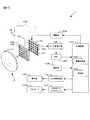
図1は、第1の実施の形態によるデジタルカメラの構成を示す図である。デジタルカメラ1は、撮影レンズL1を有する交換レンズ2が着脱可能に構成されている。デジタルカメラ1は、撮像ユニット100,制御回路101,A/D変換回路102、メモリ103,駆動部104、メモリカードインタフェース107、操作部108、表示器109およびLCD駆動回路110を備える。撮像ユニット100は、多数のマイクロレンズ120が二次元状に配列されたマイクロレンズアレイ12および撮像素子13を備える。なお、図1においては、z軸を撮影レンズL1の光軸に平行となるように設定され、z軸と直交する平面内でx軸とy軸とが互いに直交する方向に設定されている。 FIG. 1 is a diagram illustrating a configuration of a digital camera according to the first embodiment. The
撮影レンズL1は、複数の光学レンズ群から構成され、被写界からの光束をその焦点面近傍に結像する。なお、図1では撮影レンズL1を説明の都合上1枚のレンズで代表して表している。撮影レンズL1の焦点面近傍に、マイクロレンズアレイ12と撮像素子13とが順に配置される。撮像素子13は、複数の光電変換素子を備えたCCDやCMOSイメージセンサによって構成される。撮像素子13は、撮像面上に結像されている被写体像を撮像し、駆動部104により制御されて被写体像に応じた光電変換信号(画像信号)をA/D変換回路102へ出力する。なお、撮像ユニット100の詳細については説明を後述する。駆動部104は、制御回路101からの命令に応じて、撮像素子13にタイミング信号を出力し、撮像素子13の駆動タイミングを制御する。 The taking lens L1 is composed of a plurality of optical lens groups, and forms an image of a light flux from the object field in the vicinity of the focal plane. In FIG. 1, the taking lens L1 is represented by a single lens for convenience of explanation. In the vicinity of the focal plane of the photographic lens L1, the
A/D変換回路102は、撮像素子13が出力する画像信号にアナログ的な処理をしてからデジタル画像信号に変換する回路である。制御回路101は、制御プログラムに基づいて、デジタルカメラ1を構成する各部から入力される信号を用いて所定の演算を行い、デジタルカメラ1の各部に対する制御信号を送出して、撮影動作を制御する。制御回路101は、画像処理部105および演算部106を機能的に備える。画像処理部105は、A/D変換回路102によりデジタル変換された画像信号に対して種々の画像処理を施して画像データを生成する。そして、画像処理部105は生成した画像データに対してJPEG圧縮処理を施し、EXIFなどの形式でメモリカード107aへ記録する。演算部106は、上記の画像処理部105により行われる各種の画像処理のための演算処理を行う。 The A /
メモリ103は、A/D変換回路102によりデジタル変換された画像信号や、画像処理、画像圧縮処理および表示用画像データ作成処理の途中や処理後のデータを一時的に格納するために使用される揮発性記憶媒体である。メモリカードインタフェース107は、メモリカード107aが着脱可能なインタフェースである。メモリカードインタフェース107は、制御回路101の制御に応じて、画像データをメモリカード107aに書き込んだり、メモリカード107aに記録されている画像データを読み出すインタフェース回路である。メモリカード107aはコンパクトフラッシュ(登録商標)やSDカードなどの半導体メモリカードである。 The
LCD駆動回路110は、制御回路101の命令に基づいて表示器109を駆動する回路である。表示器109は、たとえば液晶等により構成され、再生モードにおいてメモリカード107aに記録されている画像データに基づいて制御回路101で作成された表示データの表示を行う。また、表示器109には、デジタルカメラ1の各種動作を設定するためのメニュー画面が表示される。LCD駆動回路110および表示器109の詳細については説明を後述する。 The
操作部108は、ユーザの操作を受け付けて、操作内容に応じた各種の操作信号を制御回路101へ出力する。操作部108は、電源ボタン、レリーズボタン、モード選択ボタン、その他の設定メニューの表示切換ボタン、設定メニュー決定ボタン等を含む。モード選択ボタンは、デジタルカメラ1の動作を撮影モードと再生モードとの間で切り替えるための操作をする際に用いられる。また、デジタルカメラ1は、撮影モードとして、複数の視点数の画像(多視点画像)を撮影するための多視点画像生成モードを含む。多視点画像生成モードでは、ユーザにより撮影する画像の視点数、視差、視点変化の方向、被写界深度等の視点条件を選択可能に構成されている。多視点画像生成モードにおける視点条件の選択は、上述したメニュー画面上から操作部108を操作することにより行われる。 The
次に、撮像ユニット100の構成について詳細に説明する。撮像ユニット100は、上述したようにマイクロレンズアレイ12と撮像素子13とを有する。マイクロレンズアレイ12は、二次元状に配列された複数のマイクロレンズ120により構成される。撮像素子13には、上記の各マイクロレンズ120を通過した光を受光する画素配列130が、マイクロレンズ120に対応した配置パターンで配置されている。各々の画素配列130は、二次元状に配列された複数の光電変換素子131(以下、撮像画素131と呼ぶ)により構成される。 Next, the configuration of the
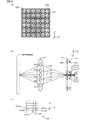
図2にマイクロレンズ120と撮像素子13の配置の一例を示す。図2(a)は、撮影レンズL1の光軸方向と直交する方向(xy平面)における、マイクロレンズ120および撮像素子13の撮像画素131の配置の一例を説明する図である。図2(a)に示すマイクロレンズアレイ12には、x軸方向に6個のマイクロレンズ120とy軸方向に6個のマイクロレンズ120、すなわち6×6個のマイクロレンズ120が配列されている。1つのマイクロレンズ120には、1つの画素配列130が対応して設けられる。個々の画素配列130は、x軸方向に5個の撮像画素131とy軸方向に5個の撮像画素131、すなわち5×5個の撮像画素131を備える。すなわち、1つのマイクロレンズ120に対して、5×5個の撮像画素131が配置されている。その結果、本実施の形態においては、撮像素子13は30×30個の撮像画素131を有している。 FIG. 2 shows an example of the arrangement of the
図2(b)は、撮影レンズL1の光軸方向(z軸方向)における、撮影レンズL1とマイクロレンズ120と撮像素子13との位置関係を説明する図である。図2(b)に示すように、マイクロレンズ120は、被写体(物体面)の像を捕らえる撮影レンズL1の焦点位置(結像面)、すなわち物体面と共役な位置に配置される。撮像素子13はマイクロレンズ120の焦点距離だけ離れた位置に配置される。その結果、撮像素子13の撮像面が撮影レンズL1と共役となっている。なお、図2(b)においては、物体面に撮影レンズL1の焦点があっている場合、すなわち撮影レンズL1からの光束がマイクロレンズ120上で結像している場合を示している。 FIG. 2B is a diagram for explaining the positional relationship among the photographing lens L1, the
図2(b)において、撮像画素131aiに対応するマイクロレンズ120による、撮影レンズL1の瞳面への投影像が占める領域が、撮影レンズL1の瞳上の部分領域P1である。部分領域P1と同様に、部分領域P2,P3,…は、撮像画素131bi,131ci,…に対応する。撮影レンズL1の瞳上の部分領域P1,P2,P3,…を透過した光束r1,r2,r3,・・・はそれぞれ、マイクロレンズを透過して撮像画素131ai,131bi,131ci,…に入射する。なお、図2(b)では、撮影レンズL1の光軸上に配置されたマイクロレンズ120へ入射する光束r1〜r5を代表して示しているが、光軸から離れた位置に設けられたマイクロレンズ120についても同様に各光束r1〜r5が入射し、対応する撮像画素131に導かれる。また、部分領域P1,P2,P3,・・・は実際には二次元状に、すなわちy軸方向にも存在するが、ここでは説明を簡単にするためx軸方向の配列のみを考える。 In FIG. 2B, the region occupied by the projection image on the pupil plane of the photographing lens L1 by the
図2(c)は、1つの画素配列130i上における撮像画素131ai〜131diの位置関係を示す。なお、図2(b)ではx軸方における撮影レンズL1の部分領域P1〜P5を例としているので、各光束r1〜r5はx軸方向に並んで配置された撮像画素131ai〜131diにそれぞれ入射する。そして、各撮像画素131ai,131bi,131ci,・・・は、それぞれ画像信号ai,bi,ci,・・・を出力する。 FIG. 2C shows the positional relationship between the imaging pixels 131ai to 131di on one
上記のように構成された撮像ユニット100から出力された画像信号を用いて、デジタルカメラ1の画像処理部105により多視点(多視差)画像を生成するための処理が行われる。また、本実施の形態のデジタルカメラ1のLCD駆動回路110および表示器109は、生成された多視点(多視差)画像を立体画像(3D画像)として表示可能に構成されている。以下、(A)多視点(多視差)画像の生成原理、(B)多視点画像間で視差が発生する原理、(C)多視点画像の生成処理、(D)立体表示について説明する。 Using the image signal output from the
(A)多視点(多視差)画像の生成原理
撮像ユニット100に含まれる各撮像画素131から出力される画像信号を用いて、被写体からの光束の位置と方向とがそれぞれ独立に検出される。被写体からの光束の位置はマイクロレンズ120の数に応じて検出できる。そのため、画像信号に基づいて生成される画像データの画素数、すなわち解像度はマイクロレンズ120の数によって制限されることになる。図2(a)に示すように、マイクロレンズアレイ12が6×6個のマイクロレンズ120を有している場合には、画像データの解像度は36(=6×6)となる。(A) Generation Principle of Multi-viewpoint (Multi-Parallax) Image Using the image signal output from each
視点の方向は1つのマイクロレンズ120に対応して設けられた撮像画素131の数に応じて検出される。上述したように、撮影レンズL1の瞳面と撮像素子13の撮像面とは共役なので、1つの画素配列130に含まれる撮像画素131の数と同数の部分領域Pが撮影レンズL1の瞳面で分割されることになる。画像処理部105は、この各部分領域Pを通過した光束rに対応する画像信号ごとに画像データを生成する。その結果、画像処理部105は、同一の被写体に対して視点の異なる部分領域Pの数と同数、すなわち、1つの画素配列130に含まれる撮像画素131の数と同数の画像データを生成する。図2(a)に示す場合のように、1つのマイクロレンズ120に対して5×5個の撮像画素131が配置されている場合には、5×5個の視点を検出できるので、画像処理部105は5×5個の視点が異なる画像データを生成する。 The direction of the viewpoint is detected according to the number of
さらに、画像処理部105は、1つの画素配列130で規定される領域を複数の抽出領域(たとえば矩形領域)に分割し、抽出領域に含まれる複数の撮像画素131から出力される画素信号を用いて画像データを生成する。この場合には、画像処理部105は抽出領域の数と同数の視点数の画像データを生成する。換言すると、抽出領域の数と同数の部分領域Pが撮影レンズL1の瞳面で分割されることになり、画像処理部105は、この各部分領域Pを通過した光束rに対応する画像信号ごとに画像データを生成する。なお、以後の説明では、抽出領域をブロックと呼ぶ。また、ブロックの大きさは、メニュー画面上でユーザによる操作部108を用いた選択、設定処理を行うことにより設定可能に構成されているものとする。設定処理の詳細については、説明を後述する。 Furthermore, the
図3を用いてブロックの大きさと視点数との関係について説明する。図3では、ユーザによりブロックBloの大きさが1に設定された場合、すなわち1つのブロックBloに1つの撮像画素131が含まれる場合を示す。なお、図3では、説明の都合上、x軸方向の視点数についてのみ示す。図3(a)は、撮像素子13に含まれる複数の画素配列130のうちの1つの画素配列130iを一例として示す。 The relationship between the block size and the number of viewpoints will be described with reference to FIG. FIG. 3 shows a case where the size of the block Blo is set to 1 by the user, that is, a case where one
この場合、画像処理部15は、撮像素子13から出力された画像信号の中から、図3(a)に示す画素配列130に含まれる撮像画素131aiから出力された画像信号aiを抽出する。さらに、画像処理部105は、撮像素子13に含まれる全ての画素配列130のそれぞれの撮像画素131aから出力された画像信号aを抽出する。そして、画像処理部105は、抽出した全ての画像信号aを用いて1つの画像データIm_aを生成する。同様に、画像処理部105は、各画素配列130に含まれるそれぞれの撮像画素131b,・・・,131eから出力された画像信号b,・・・,eを用いて画像データIm_b,・・・,Im_eを生成する。その結果、図3(b)に示すように、画像処理部105は5つ(5視点)の画像データIm_a,Im_b,・・・,Im_eを生成する。 In this case, the image processing unit 15 extracts the image signal ai output from the imaging pixel 131ai included in the
図4を用いてブロックBloの大きさと視点数との関係について説明する。図4(a)は、ユーザによりブロックBloの大きさが2×3に設定された場合、すなわち1つのブロックBloに6(=2×3)個の撮像画素131が含まれる場合を示す。なお、図4についても図3と同様に、説明の都合上、x軸方向の視点数についてのみ示す。図4(a)は、撮像素子13に含まれる複数の画素配列130のうちの1つの画素配列130iを一例として示す。また、ブロックBlo_bi(図4(a)の縦線領域),Blo_ci(図4(a)のドット領域),Blo_di(図4(a)の横線領域)は、ブロックBlo_ai(図4(a)の斜線領域)を1画素ずつ順次移動させたものである。 The relationship between the size of the block Blo and the number of viewpoints will be described with reference to FIG. FIG. 4A shows a case where the size of the block Blo is set to 2 × 3 by the user, that is, a case where 6 (= 2 × 3) imaging
この場合、画像処理部15は、撮像素子13から出力された画像信号の中から、画素配列130のブロックBlo_aiに含まれる6(2×3)個の撮像画素131から出力される画像信号を加算して、1つの画像信号aiを抽出する。さらに、画像処理部105は、撮像素子13に含まれる全ての画素配列130のそれぞれのブロックBlo_a内の撮像画素131から出力された画像信号aを抽出する。そして、画像処理部105は、抽出した全ての画像信号aを用いて1つの画像データIm_aを生成する。同様に、画像処理部105は、各画素配列130に含まれるそれぞれのブロックBlo_b,・・・,Blo_di内の撮像画素131からの出力についても同様の処理を行って画像データIm_b,・・・,Im_dを生成する。その結果、図4(b)に示すように、画像処理部105は4つ(4視点)の画像データIm_a,Im_b,・・・,Im_dを生成する。 In this case, the image processing unit 15 adds the image signals output from 6 (2 × 3) imaging
上述したようにブロックBloの数と同数の部分領域Pが撮影レンズL1の瞳面で分割されるので、撮影レンズL1の部分領域Pの大きさは設定されたブロックBloの大きさに応じて決まる。このため、撮像素子13によって検出される各画素(すなわちブロックBloの大きさ)は、撮像素子13と共役関係にある撮影レンズL1の部分領域Pの大きさ、すなわち光束の大きさ(径)を規定することになる。したがって、設定されたブロックBloの大きさは撮影レンズL1のF値に相当することになり、ブロックBloの大きさが小さいほどF値が大きくなる。 As described above, the same number of partial areas P as the number of blocks Blo are divided by the pupil plane of the taking lens L1, so that the size of the partial area P of the taking lens L1 is determined according to the set size of the block Blo. . For this reason, each pixel (that is, the size of the block Blo) detected by the
図3を用いて説明した場合のように、ブロックBloの大きさが1に設定されている場合は、画像処理部105は、1つのマイクロレンズ120に対して1つの撮像画素131から出力された画像信号に基づいて、5つの画像データIm_a〜Im_eを生成している。したがって、ブロックBloの大きさが1に設定された場合はF値が大きくなるので、生成された画像データIm_a〜Im_eのそれぞれに対応する画像の被写界深度が深くなる。 As in the case described with reference to FIG. 3, when the size of the block Blo is set to 1, the
図4を用いて説明した場合のように、ブロックBloの大きさが2×3に設定されている場合は、画像処理部105は、1つのマイクロレンズ120に対して6個の撮像画素131から出力された画像信号に基づいて画像データを生成している。この場合の撮影レンズL1の部分領域Pは、図3の場合における撮影レンズL1の部分領域Pの大きさよりも6倍の大きさを有するので、ブロックBlo内の撮像画素131に入射する光束は6倍の大きさ(径)となる。したがって、ブロックBloの大きさが2×3に設定された場合はF値が小さくなるので、生成された画像データIm_a〜Im_dのそれぞれに対応する画像の被写界深度が浅くなる。この結果、ブロックBloの大きさを大きく設定することにより、通常の一眼レフカメラ等を用いて撮影した、主要被写体にのみピントを合わせ背景や前景をぼかした写真と同様の画像が本実施の形態のデジタルカメラ1によって生成される。 As in the case described with reference to FIG. 4, when the size of the block Blo is set to 2 × 3, the
なお、上述の説明では視点の移動方向をx軸方向として説明したが、視点はy軸方向に移動するものでも、xy平面上を二次元方向に移動するものでもよい。また、ブロックBloの形状についても矩形に限定されるものではない。 In the above description, the movement direction of the viewpoint is described as the x-axis direction, but the viewpoint may move in the y-axis direction or may move in the two-dimensional direction on the xy plane. Further, the shape of the block Blo is not limited to a rectangle.
(B)多視点画像間で視差が発生する原理
上記のようにして生成された複数の視点画像のそれぞれについて視差が生じる場合と生じない場合について説明する。まず、図5を用いて、複数の視点画像のそれぞれについて視差が生じない場合について説明する。図5(a)は撮像側で5つの視点画像を生成する場合の光束r1〜r5を説明する図である。図5(b)は、図5(a)に示す光束r1〜r5のうち、撮影レンズL1と焦点面(結像面)付近での光束r1〜r5を拡大して示す図である。さらに、図5(c)は、図5(b)に示す光束r1〜r5のうち、マイクロレンズアレイ12および撮像素子13付近での光束を拡大して示す図である。(B) Principle of generating parallax between multi-viewpoint images A case where parallax occurs and a case where no parallax occurs for each of the plurality of viewpoint images generated as described above will be described. First, the case where parallax does not arise about each of several viewpoint images is demonstrated using FIG. FIG. 5A is a diagram illustrating light beams r1 to r5 when five viewpoint images are generated on the imaging side. FIG. 5B is an enlarged view of the light beams r1 to r5 in the vicinity of the photographing lens L1 and the focal plane (imaging plane) among the light beams r1 to r5 illustrated in FIG. Further, FIG. 5C is an enlarged view of the light beams in the vicinity of the
図5において、5つの視点の位置は図2〜図4に示す撮像画素131ai〜131eiと同様である。図5(a)に示すように、1つのマイクロレンズ120に対応して設けられた撮像画素131ai〜131eiのそれぞれに入射する光線は、物体面Q1上で同じ点で交わっている。したがって、物体面Q1に存在する被写体については、視点画像データIm_a〜Im_eのそれぞれに対応する画像上で視差が生じない。これに対して、物体面Q1から外れた面Q2で交わる光束r1〜r5は、異なるマイクロレンズ120に導かれる。したがって、物体面Q1から外れた面Q2に存在する被写体については、視点画像データIm_a〜Im_eのそれぞれに対応する画像上で視差が生じる。以下、視差が生じる場合と生じない場合とについて、詳細に説明する。 In FIG. 5, the positions of the five viewpoints are the same as those of the imaging pixels 131ai to 131ei shown in FIGS. As shown in FIG. 5A, the light rays incident on each of the imaging pixels 131ai to 131ei provided corresponding to one
−視差が生じない場合−
図6を参照しながら、複数の視点画像のそれぞれについて視差が生じない場合について説明する。図6(a)は、焦点面に結像した被写体「A」の像を撮影して生成された5つの視点画像データIm_a〜Im_eに対応する視点画像Ai〜Eiを示す。すなわち、視点画像Ai〜Eiは、撮像画素131ai〜131eiから出力された画像信号にそれぞれ対応している。図6(b)は撮像素子13に入射する光束の様子を示す。図6(b)では、紙面の上下方向をz軸方向とし、z=0をマイクロレンズ120の面、すなわち焦点面に設定している。焦点面(z=0)に結像した被写体「A」の像の位置をX1〜X9として表す。-When parallax does not occur-
A case where no parallax occurs for each of the plurality of viewpoint images will be described with reference to FIG. FIG. 6A shows viewpoint images Ai to Ei corresponding to five viewpoint image data Im_a to Im_e generated by photographing an image of the subject “A” formed on the focal plane. That is, the viewpoint images Ai to Ei correspond to the image signals output from the imaging pixels 131ai to 131ei, respectively. FIG. 6B shows the state of the light beam incident on the
X5の位置に結像した像を形成する光束r1〜r5は、マイクロレンズ1205を介して撮像画素131a5〜131e5にそれぞれ入射する。また、X6の位置に結像した像を形成する光束r1〜r5は、マイクロレンズ1206を介して撮像画素131a6〜131e6にそれぞれ入射する。すなわち、撮像素子13上の撮像画素131a1,131a2,131a3,・・・は、光束r1を受光して画像信号を出力している。その結果、撮像画素131a1,131a2,・・・は位置X1,X2,・・・の像を撮像していることになる。Light beam r1~r5 forming the formed image to the position of X5, respectively incident on the imaging pixels 131a5~131e5 through the
同様に、撮像画素131b1,131b2,・・・は光束r2を受光し、撮像画素131c1,131c2,・・・は光束r3を受光し、撮像画素131d1,131d2,・・・は光束r4を受光し、撮像画素131e1,131e2,・・・は光束r5を受光する。その結果、撮像画素131a1,131a2,・・・が撮像する像、撮像画素131b1,131b2,・・・が撮像する像、撮像画素131c1,131c2,・・・が撮像する像、撮像画素131d1,131d2,・・・が撮像する像、撮像画素131e1,131e2,・・・が撮像する像は、いずれも位置X1,X2,・・・の像となる。したがって、図6(a)に示すように、撮像画素131ai〜131eiから出力されたそれぞれの画像信号に基づいて生成される5つの視点画像Ai〜Eiは、同一の画像となるため視差が生じない。 Similarly, the imaging pixels 131b1, 131b2,... Receive the light beam r2, the imaging pixels 131c1, 131c2,... Receive the light beam r3, and the imaging pixels 131d1, 131d2,. The imaging pixels 131e1, 131e2,... Receive the light beam r5. As a result, images captured by the imaging pixels 131a1, 131a2,..., Images captured by the imaging pixels 131b1, 131b2,..., Images captured by the imaging pixels 131c1, 131c2,. ,... And the images captured by the imaging pixels 131e1, 131e2,... Are images at positions X1, X2,. Accordingly, as shown in FIG. 6A, the five viewpoint images Ai to Ei generated based on the respective image signals output from the imaging pixels 131ai to 131ei are the same image, and thus no parallax occurs. .
−視差が生じる場合−
図7を参照しながら、複数の視点画像のそれぞれについて視差が生じない場合について説明する。図7(a)は、焦点面とは異なる面に結像した被写体「A」の像を撮影して生成された5つの視点画像Ai〜Eiを示す。図6(a)の場合と同様に、視点画像Ai〜Eiは、撮像画素131ai〜131eiから出力された画像信号にそれぞれ対応している。図7(b)は撮像素子13に入射する光束の様子を示す。図7(b)においても、紙面の上下方向をz軸方向とし、z=0をマイクロレンズ120の面、すなわち焦点面に設定している。焦点面とは異なる面(z=h1)に結像した被写体「A」の像の位置をX1〜X9として表す。-When parallax occurs-
A case where no parallax occurs for each of the plurality of viewpoint images will be described with reference to FIG. FIG. 7A shows five viewpoint images Ai to Ei generated by photographing an image of the subject “A” formed on a plane different from the focal plane. As in the case of FIG. 6A, the viewpoint images Ai to Ei correspond to the image signals output from the imaging pixels 131ai to 131ei, respectively. FIG. 7B shows the state of the light beam incident on the
X5の位置に結像した像を形成する光束r1〜r5のうち光束r1は、マイクロレンズ1203を介して撮像画素131a3へ入射する。また、光束r2はマイクロレンズ1204を介して撮像画素131b4へ、光束r3はマイクロレンズ1205を介して撮像画素131c5へ、光束r4はマイクロレンズ1206を介して撮像画素131d6へ、光束r5はマイクロレンズ1207を介して撮像画素131e7へ入射する。同様に、X6の位置に結像した像を形成する光束r1〜r5のうち光束r1は、撮像画素131a4へ、光束r2は撮像画素131b5へ、光束r3は撮像画素131c6へ、光束r4は撮像画素131d7へ、光束r5は撮像画素131e8へ入射する。その結果、異なる位置に結像した像を形成する光束r1〜r5のそれぞれは、異なるマイクロレンズ120を介して撮像素子13に入射する。Of light beams r1 of the light beam r1~r5 forming the formed image to the position of the X5 is incident to the image pickup pixel 131a3 through the
したがって、撮像素子13上の撮像画素131a1,131a2,131a3,・・・は、光束r1を受光して画像信号を出力している。すなわち、撮像画素131a1,131a2,131a3・・・は位置X3、X4、X5・・・の像を撮像していることになる。また、撮像素子13上の撮像画素131b1,131b2,131b3,・・・は光束r2を受光するので、位置X2,X3,X4・・・の像を撮像していることになる。同様に、撮像画素131c1,131c2,131c3,・・・は光束r3を受光して位置X1,X2,X3・・・の像を撮像し、撮像画素131d1,131d2,131d3,・・・は光束r4を受光して位置X0(不図示),X1,X2・・・の像を撮像し、撮像画素131e1,131e2,131e3,・・・は光束r5を受光して位置X(−1)(不図示),X0(不図示),X1,・・・の像を撮像している。 Therefore, the imaging pixels 131a1, 131a2, 131a3,... On the
その結果、撮像画素131a1,131a2,・・・が撮像する像、撮像画素131b1,131b2,・・・が撮像する像、撮像画素131c1,131c2,・・・が撮像する像、撮像画素131d1,131d2,・・・が撮像する像、撮像画素131e1,131e2,・・・が撮像する像は、その位置がx軸方向に少しずつずれたものとなる。したがって、図7(a)に示すように、撮像画素131ai〜131eiから出力されたそれぞれの画像信号に基づいて生成される5つの視点画像Ai〜Eiは、同一の画像とはならないので視差が生じることになる。このようにして、デジタルカメラ1に対する物体面の奥行き、すなわち距離情報が取得された複数の視点画像間において視差となって現れる。この視差は3次元表示可能な表示素子上においては立体情報として扱うことができる。 As a result, images captured by the imaging pixels 131a1, 131a2,..., Images captured by the imaging pixels 131b1, 131b2,..., Images captured by the imaging pixels 131c1, 131c2,. ,..., And the images captured by the imaging pixels 131e1, 131e2,... Are shifted little by little in the x-axis direction. Accordingly, as shown in FIG. 7A, the five viewpoint images Ai to Ei generated based on the respective image signals output from the imaging pixels 131ai to 131ei do not become the same image, and thus parallax occurs. It will be. In this way, the depth of the object plane with respect to the
(C)多視点画像の生成処理
以下、第1の実施の形態におけるデジタルカメラ1による多視点(多視差)画像の生成処理、すなわち多視点画像生成モードが設定された場合のデジタルカメラ1の動作について説明する。なお、多視点画像生成モードは、ユーザによるモード選択ボタンの操作に応じて多視点画像生成モードが選択され、操作部108から操作信号が入力されると、制御回路101により設定される。(C) Multi-viewpoint image generation processing Hereinafter, the multi-viewpoint (multi-parallax) image generation processing by the
多視点画像生成モードでは、上述したように、ユーザにより視点画像(すなわち3次元画像)の特性、すなわち視点条件が選択可能となるように構成されている。選択可能な特性として、視点変化の方向、視点数、視点の変化量、視点生成の画素数(ブロックBloの大きさ)がある。これらの特性は、上述した表示器109に表示されるメニュー画面上から、ユーザが操作部108を用いて選択操作することにより設定される。演算部106は、上記の特性に対応するパラメータを可変パラメータとして、視点画像データを生成する際の演算処理に用いる。 In the multi-viewpoint image generation mode, as described above, the characteristics of the viewpoint image (that is, the three-dimensional image), that is, the viewpoint condition can be selected by the user. The selectable characteristics include the direction of viewpoint change, the number of viewpoints, the amount of viewpoint change, and the number of pixels for viewpoint generation (the size of block Bl). These characteristics are set when the user performs a selection operation using the
図8(a)に各種可変パラメータと、可変パラメータにより制御可能となる特性を示す。図8(a)に示す「ブロック内の画素(撮像画素131)数u、v」はブロックBloの大きさを決定するための可変パラメータであり、設定されたブロックBlo内の画素数に応じて、上述したように視点画像の被写界深度が決定される。なお、uはブロックBlo内のx軸方向の画素数、vはブロックBlo内のy軸方向の画素数を示す。 FIG. 8A shows various variable parameters and characteristics that can be controlled by the variable parameters. “Number of pixels (imaging pixels 131) u, v” in the block shown in FIG. 8A is a variable parameter for determining the size of the block Blo, and depends on the number of pixels in the set block Blo. As described above, the depth of field of the viewpoint image is determined. Note that u represents the number of pixels in the x-axis direction in the block Blo, and v represents the number of pixels in the y-axis direction in the block Blo.
「ブロックの移動する回数Kx、Ky」は多視点画像の視点数を決定するための可変パラメータである。画像処理部105は、設定された回数Kx、Kyと同数の異なるブロックBloを画素配列130上に設定して、それぞれのブロックBloに含まれる撮像画素131から画像信号を抽出する。図3、図4で示したようにブロックBloが5回移動すれば5視点の画像が生成され、ブロックBloが4回移動すれば4視点の画像が生成される。 “Number of times the block moves Kx, Ky” is a variable parameter for determining the number of viewpoints of the multi-viewpoint image. The
「ブロックの移動量Sx、Sy」は複数の視点画像間の視点の変化量を決定するための可変パラメータである。ブロックBloが移動する量が大きくなるほど、視点画像間で生じる視差が大きくなる。画像処理部105は、設定された移動量Sx、Syに応じた位置間隔で画素配列130上に配列されたブロックBloから画像信号を抽出する。「ブロックの移動方向Arctan(Sy/Sx)」は視点画像の視点変化の方向を決定するための可変パラメータである。画像処理部105は、選択された移動方向に沿って画素配列130上に設定されたブロックBloから画像信号を抽出する。図3、図4で説明した例においては移動方向としてx軸方向が設定された場合を示した。「ブロックの初期位置U0、V0」は視点画像の視点の初期位置を決定するための可変パラメータである。 “Block movement amount Sx, Sy” is a variable parameter for determining a viewpoint change amount between a plurality of viewpoint images. The larger the amount that the block Blo moves, the greater the parallax that occurs between the viewpoint images. The
また、図8(b)に示すように、マイクロレンズ120の配列数M、Nおよびピッチp、q、撮像素子13の画素(撮像画素131)数Cx、Cyおよびピッチs、t、生成画像の解像度M、Nが固定パラメータとして設定されている。これらの固定パラメータはマイクロレンズ120および撮像素子13の構造に依存して決定される値である。 Further, as shown in FIG. 8B, the number of arrangements M and N of the
図3に示す5つの視点(x軸方向に5視点)画像を生成する場合には、上記の可変パラメータおよび固定パラメータの値は以下のようになる。
マイクロレンズ120のx軸方向の配列数M=6
マイクロレンズ120のy軸方向の配列数N=6
撮像素子13のx軸方向の画素数Cx=30
撮像素子13のy軸方向の画素数Cy=30
ブロックの初期位置U0=0、V0=0
ブロックの移動する回数Kx=5、Ky=1
ブロックの移動量Sx=1、Sy=0
ブロック内の画素数u=1、v=1
なお、この場合の視点画像の解像度は36(=6×6=M×N)である。When the five viewpoint images (five viewpoints in the x-axis direction) shown in FIG. 3 are generated, the values of the variable parameter and the fixed parameter are as follows.
Number of arrangement of
Number of arrangement of
Number of pixels in the x-axis direction of the
Number of pixels in the y-axis direction of the
Initial block position U0 = 0, V0 = 0
Number of times the block moves Kx = 5, Ky = 1
Block movement amount Sx = 1, Sy = 0
Number of pixels in block u = 1, v = 1
In this case, the resolution of the viewpoint image is 36 (= 6 × 6 = M × N).
図4に示す4つの多視点(水平方向に4視点)画像を生成する場合には、上記の可変パラメータおよび固定パラメータの値は以下のようになる。
マイクロレンズ120のx軸方向の配列数M=6
マイクロレンズ120のy軸方向の配列数N=6
撮像素子13のx軸方向の画素数Cx=30
撮像素子13のy軸方向の画素数Cy=30
ブロックの初期位置U0=0、V0=0
ブロックの移動する回数Kx=4、Ky=1
ブロックの移動量Sx=1、Sy=0
ブロック内の画素数u=2、v=3
なお、この場合の視点画像の解像度は36(=6×6=M×N)である。When the four multi-viewpoint images (four viewpoints in the horizontal direction) shown in FIG. 4 are generated, the values of the variable parameter and the fixed parameter are as follows.
Number of arrangement of
Number of arrangement of
Number of pixels in the x-axis direction of the
Number of pixels in the y-axis direction of the
Initial block position U0 = 0, V0 = 0
Number of times the block moves Kx = 4, Ky = 1
Block movement amount Sx = 1, Sy = 0
Number of pixels in block u = 2, v = 3
In this case, the resolution of the viewpoint image is 36 (= 6 × 6 = M × N).
上記の各種のパラメータが設定されると、画像処理部105は、1つの被写体を撮影して取得され、メモリ103に格納された画像信号を用いて、複数の視点画像データを生成する。上述したように、画像処理部105は、1つのマイクロレンズ120に対応する画素配列130内の撮像画素131から出力された画像信号のうち、設定されたブロックBloに含まれる撮像画素131から出力された画素信号を抽出する。そして、画像処理部105は、全ての画素配列130内に対しても同様に画素信号を抽出し、抽出された複数の画素信号を用いて1つの視点画像データImを生成する。画像処理部105は、上記の処理を設定されたブロックBloの移動量Sx、Syだけ移動させながら、設定されたブロックBloの移動回数Kx、Kyだけ行うことにより、複数の視点画像データImを生成する。このとき、画像処理部105は、演算部106による演算結果に基づいて画像信号を抽出する。すなわち、演算部106は、画像処理部105が視点画像データImを生成するために抽出する画像信号を決定する。 When the above various parameters are set, the
まず、演算部106が行う演算処理について説明する。
図9(a)にxy平面におけるマイクロレンズアレイ12の座標系(m,n)を示す。この座標系では、図の左下端のマイクロレンズ120の位置を(m,n)=(0,0)として示す。なお、図9(a)においては、0≦m<6,0≦n<6である。さらに、図9(b)にxy平面における撮像素子13の座標系(i,j)を示す。図9(b)の撮像素子13の座標系において、(i,j)に配置された撮像画素131からの画素値、すなわち画像信号をI(i,j)で表す。First, arithmetic processing performed by the
FIG. 9A shows a coordinate system (m, n) of the
演算部106は、まず(m,n)=(0,0)の位置に設けられたマイクロレンズ120の中心位置(X0,Y0)を以下の式(1)を用いて算出する。なお、係数pは上述したようにマイクロレンズ120のx軸方向の配列ピッチを示す固定パラメータであり、係数qはマイクロレンズ120のy軸方向の配列ピッチを示す固定パラメータである。
X0=mp+p/2
Y0=nq+q/2 ・・・(1)The
X0 = mp + p / 2
Y0 = nq + q / 2 (1)
次に、演算部106は、マイクロレンズ120におけるブロックの初期位置(左下端)(X,Y)を、以下の式(2)を用いて算出する。係数sは上述したように撮像画素131のx軸方向の配列ピッチを示す固定パラメータであり、係数tは撮像画素131のy軸方向の配列ピッチを示す固定パラメータである。係数Nxは、x軸方向に生成する視点画像データImの個数を示すパラメータであり、0≦Nx<Kxである。係数Nyは、y軸方向に生成する視点画像データImの個数を示すパラメータであり、0≦Ny<Kyである。
X=X0+U0+s・Nx・Sx
Y=Y0+V0+t・Ny・Sy ・・・(2)Next, the
X = X0 + U0 + s · Nx · Sx
Y = Y0 + V0 + t · Ny · Sy (2)
図3に示す5視点画像データおよび図4に示す4視点画像データを生成する場合には、ブロックBloの初期位置(X,Y)は以下の式(2)’のように表される。なお、係数vは、上述したように、ブロックBlo内に含まれるy軸方向の撮像画素131の数である。
X=mp+s・Nx
Y=(n+1/2)q−tv/2 ・・・(2)’When the 5-viewpoint image data shown in FIG. 3 and the 4-viewpoint image data shown in FIG. 4 are generated, the initial position (X, Y) of the block Blo is expressed by the following equation (2) ′. Note that the coefficient v is the number of
X = mp + s · Nx
Y = (n + 1/2) q−tv / 2 (2) ′
演算部106は、式(2)を用いて算出したブロックBloの初期位置(X,Y)を撮像素子13の座標系(i,j)に換算する。このとき、演算部106は、以下の式(3)を用いる。
i=X/s
j=Y/t ・・・(3)The
i = X / s
j = Y / t (3)
図3に示す5視点画像データImを生成する場合には、ブロックBloの初期位置(X,Y)は以下の式(3)’に示す位置に換算される。なお、以下の換算は、図3においては各パラメータがU0=−p/2、V0=−tv/2、p=5s、q=5t、u=1、v=1のように表すことができることに基づいている。
i=X/s=mp+Nx=5m+Nx
j=Y/t=(n+1/2)q/t−v/2=5n+2 ・・・(3)’When the 5-viewpoint image data Im shown in FIG. 3 is generated, the initial position (X, Y) of the block Blo is converted to the position shown in the following equation (3) ′. The following conversion can be expressed in FIG. 3 such that each parameter is U0 = −p / 2, V0 = −tv / 2, p = 5s, q = 5t, u = 1, and v = 1. Based on.
i = X / s = mp + Nx = 5m + Nx
j = Y / t = (n + 1/2) q / tv / 2 = 2 = 5n + 2 (3) ′
図4に示す4視点画像データImを生成する場合には、ブロックBloの初期位置(X,Y)は以下の式(3)”に示す位置に換算される。なお、以下の換算は、図4においては各パラメータがU0=−p/2、V0=−tv/2、p=5s、q=5t、u=2、v=3のように表すことができることに基づいている。
i=X/s=mp+Nx=5m+Nx
j=Y/t=(n+1/2)q/t−v/2=5n+1 ・・・(3)”When generating the 4-viewpoint image data Im shown in FIG. 4, the initial position (X, Y) of the block Blo is converted to the position shown in the following equation (3) ". 4 is based on the fact that each parameter can be expressed as U0 = −p / 2, V0 = −tv / 2, p = 5s, q = 5t, u = 2, v = 3.
i = X / s = mp + Nx = 5m + Nx
j = Y / t = (n + 1/2) q / tv / 2 = 5n + 1 (3) "
画像処理部105は、上記の式(3)にて算出されたブロックBloの初期位置を用いて、画像信号Iを抽出する。すなわち、画像処理部105は、式(3)で算出された初期位置(i,j)に対応する画像信号を基準として、ブロックBlo内に含まれる画像信号の和(ブロック信号Ib(i,j))を算出する。この場合、画像処理部105は、以下の式(4)を用いてブロック信号Ib(i,j)を算出する。
Ib(i,j)=ΣI(i+k−1,j+l−1)
=I(i,j)+I(i,j+1)+・・・+I(i,j+v−1)
+I(i+1,j)+I(i+1,j+1)+・・・+I(i+1,j+v−1)
+I(i+2,j)+I(i+2,j+1)+・・・+I(i+2,j+v−1)
+ ・・・・
+I(i+u−1,j)+I(i+u−1,j+1)+・・・+I(i+u−1,j+v−1) ・・・(4)The
Ib (i, j) = ΣI (i + k−1, j + l−1)
= I (i, j) + I (i, j + 1) +... + I (i, j + v-1)
+ I (i + 1, j) + I (i + 1, j + 1) +... + I (i + 1, j + v-1)
+ I (i + 2, j) + I (i + 2, j + 1) +... + I (i + 2, j + v-1)
+ ・ ・ ・ ・
+ I (i + u-1, j) + I (i + u-1, j + 1) + ... + I (i + u-1, j + v-1) (4)
図3に示す5視点画像データImを生成する場合には、ブロック信号Ib(i,j)は以下の式(4)’で示す値となる。また、図4に示す4視点画像データを生成する場合には、ブロック信号Ib(i,j)は以下の式(4)’で示す値となる。
Ib(i,j)=I(i,j)=I(5m+Nx,5n+2) ・・・(4)’
Ib(i,j)=I(i,j)+I(i,j+1)+I(i,j+2)+I(i+1,j)+I(i+1,j+1)+I(i+1,j+2) ・・・(4)”When the 5-viewpoint image data Im shown in FIG. 3 is generated, the block signal Ib (i, j) has a value represented by the following expression (4) ′. In addition, when the 4-viewpoint image data shown in FIG. 4 is generated, the block signal Ib (i, j) has a value represented by the following expression (4) ′.
Ib (i, j) = I (i, j) = I (5m + Nx, 5n + 2) (4) ′
Ib (i, j) = I (i, j) + I (i, j + 1) + I (i, j + 2) + I (i + 1, j) + I (i + 1, j + 1) + I (i + 1, j + 2) (4) "
以上の処理を全てのマイクロレンズ120に対して行って生成されたブロック信号Ib(i,j)を用いて、画像処理部105は1つの視点画像データImを生成する。すなわち、画像処理部105は、ブロック信号Ib(i,j)が視点画像データIm内で1つの画素値を表すように、各ブロック信号Ibを加算する。その後、演算部106は、ブロックBloを設定された移動方向(Arctan(Sy/Sx)に設定された移動量Sx、Syずつ移動させた場合のブロックBloの初期位置(i,j)を新たに算出する。そして、画像処理部105は、新たに算出されたブロックBloの初期位置(i,j)に基づいて式(4)を用いて新たにブロック信号Ib(i,j)を算出し、異なる1つの視点画像データImを生成する。画像処理部105は、上記の処理を設定された移動回数Kx、Ky分繰り返して、複数の視点画像データImを生成する。 The
画像処理部105は、上述のようにして生成した複数の視点画像データImを用いて多視点画像ファイルを生成してメモリカード107aに記録する。なお、画像処理部105は、生成した視点画像データImのそれぞれに関連付けを行ってメモリカード107aに記録するようにしてもよい。 The
図10のフローチャートを用いて、以上で説明した多視点画像生成処理について説明する。図10に示す各処理は、制御回路101内の図示しないメモリに記録され、多視点画像生成モードが設定された状態で撮影処理により取得された画像信号がメモリ103内に格納されると、制御回路101により起動され、実行される。
ステップS101では、視点画像を生成する個数(Nx,Ny)の値を初期値である0に設定してステップS102へ進む。ステップS102では、マイクロレンズ120の初期位置としてm,nの値を0に設定してステップS103へ進む。The multi-viewpoint image generation process described above will be described using the flowchart of FIG. Each process shown in FIG. 10 is recorded in a memory (not shown) in the
In step S101, the number of viewpoint images to be generated (Nx, Ny) is set to 0, which is an initial value, and the process proceeds to step S102. In step S102, the values of m and n are set to 0 as the initial position of the
ステップS103では、式(1)を用いて対象となるマイクロレンズ120の中心位置を算出してステップS104へ進む。ステップS104では、式(2)を用いて、マイクロレンズ120の座標系におけるブロックBloの初期位置、すなわち左下端部の座標を算出してステップS105へ進む。ステップS105では、ステップS104で算出した座標値を、式(3)を用いて撮像素子13の座標系(i,j)に換算してステップS106へ進む。 In step S103, the center position of the
ステップS106では、式(4)を用いて、ブロックに含まれる光電変換信号131から出力された画像信号を加算し、ブロック信号Ibを生成してステップS107へ進む。ステップS107では、次のマイクロレンズ120へ移動(m=m+1またはn=n+1)してステップS108へ進む。ステップS108では、全てのマイクロレンズ120に対応する画素配列130に対して処理が終了したか否かを判定する。全ての画素配列130に対して処理が終了した場合、すなわちm=Mかつn=Nの場合には、ステップS109へ進む。全ての画素配列130に対して処理が終了していない場合には、ステップS109が否定判定されてステップS103へ戻る。 In step S106, the image signal output from the
ステップS109では、各画素配列130ごとに生成されたブロック信号Ibを合成して1つの視点画像データImを生成してステップS110へ進む。ステップS110では、ブロックの位置を設定された移動量であるSx,Syだけ移動させる。そして、視点画像の個数をNx=Nx+1またはNy=Ny+1に設定してステップS111へ進む。 In step S109, the block signals Ib generated for each
ステップS111では、設定された視点数(Kx,Ky)分の視点画像データImが生成されたか否かを判定する。設定された視点数の視点画像データImが生成された場合、すなわちNx=KxかつNy=Kyの場合には、ステップS111が肯定判定されてステップS112へ進む。設定された視点数の視点画像データImが生成されていない場合には、ステップS111が否定判定されてステップS102へ戻る。ステップS112では、生成されたKx×Ky個の視点画像データImを用いて多視点画像ファイルを生成し、メモリカード107aに記録させて処理を終了する。 In step S111, it is determined whether viewpoint image data Im for the set number of viewpoints (Kx, Ky) has been generated. When viewpoint image data Im having the set number of viewpoints has been generated, that is, when Nx = Kx and Ny = Ky, an affirmative determination is made in step S111 and the process proceeds to step S112. If viewpoint image data Im having the set number of viewpoints has not been generated, a negative determination is made in step S1111 and the process returns to step S102. In step S112, a multi-viewpoint image file is generated using the generated Kx × Ky viewpoint image data Im, recorded in the
(D)立体表示
上述のようにして生成された複数の視点画像データImのそれぞれに対応する視点画像を表示器109に立体画像として表示させるための処理について説明する。
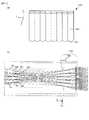
図11に示すように表示器109は、その表面に、円筒形を軸方向に切断したような形状を有する凸レンズ151を複数有するレンチキュラーレンズ150を備える。すなわち表示器109は、公知のレンチキュラー方式により複数の視点画像を立体画像として表示する。図11(a)に示すように、本実施の形態においては、レンチキュラーレンズ150の個々の凸レンズ151の長辺方向をy軸方向に揃えて配置されている。なお、以下の説明においても、代表してx軸方向の処理を中心に行う。(D) Stereoscopic Display A process for displaying the viewpoint images corresponding to each of the plurality of viewpoint image data Im generated as described above as a stereoscopic image on the
As shown in FIG. 11, the
図11(b)には、表示器109のxz平面における断面図を示す。レンチキュラーレンズ150の個々の凸レンズ151は、表示器109を構成する、y軸方向に沿った複数の画素列Coからの光を集光してユーザへ導く。図11(b)では、1つの凸レンズ151aが表示器109の画素列Co1_1〜Co1_5から発せられた光を集光している。そして、複数の凸レンズ151から導かれる光のうち、画素列Co1_1,Co2_1,Co3_1,・・・からの光は、点W1で結像する。同様に、画素列Co1_2,Co2_2,Co3_2,・・・からの光は点W2で、画素列Co1_3,Co2_3,Co3_3,・・・からの光は点W3で、画素列Co1_4,Co2_4,Co3_4,・・・からの光は点W4で、画素列Co1_5,Co2_5,Co3_5,・・・からの光は点W5で結像する。 FIG. 11B shows a cross-sectional view of the
したがって、ユーザ(閲覧者)がH1の位置から表示器109に表示された画像を観察する場合、右目で点W1の像、すなわち画素列Co1_1,Co2_1,Co3_1,・・・からの光を観察し、左目で点W2の像、すなわち画素列Co1_2,Co2_2,Co3_2,・・・からの光を観察する。また、ユーザがH2の位置から画像を観察する場合は、右目で点W4の像(画素列Co1_4,Co2_4,Co3_4,・・・からの光)を観察し、左目で点W5の像(画素列Co1_5,Co2_5,Co3_5,・・・からの光)を観察する。 Accordingly, when the user (viewer) observes the image displayed on the
なお、表示器109は、パララックスバリア方式により複数の視点画像を立体画像として表示させてもよい。この場合、図11のレンチキュラーレンズ150が配置されている位置に、y軸方向に長辺をそろえた複数の細長い開口を有するマスク(バリア)を配置すればよい。 The
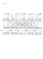
図12に示す概念図を用いて、上記のように立体画像が表示可能な表示器109へ出力する表示用データを生成する処理を説明する。同一の被写界を撮影した、視差のある多視点画像(たとえば5つの視点)に対応する視点画像データをIm1,Im2,・・・,Im5とする。この場合、画像処理部105は、視点画像データをIm1,Im2,・・・,Im5からそれぞれ同一の画素列Co1に対応する画像データを抽出して合成することにより1つの表示用画像データId1を作成する。さらに、画像処理部105は、視点画像データIm1,Im2,・・・,Im5のそれぞれから画素列Co2に対応する画像データを抽出して、1つの表示用画像データId2を作成する。以下同様にして画像処理部105は表示用画像データId3〜Id5を作成する。 A process for generating display data to be output to the
各表示用画像データId1〜Id5が作成されると、画像処理部105は、LCD駆動制御部110に表示用画像データId1を出力して、表示器109のCo1に表示用画像データId1に対応する画像を表示させる。同様に、画像処理部105は、LCD駆動制御部110に表示用画像データId2〜Id5を出力して、表示器109のCo2〜Co5にそれぞれ表示用画像データId2〜Id5に対応する画像を表示させる。 When each of the display image data Id1 to Id5 is created, the
上述したように、画素列Co1_1,Co2_1,Co3_1,・・・からの光は、点W1で結像するので、視点画像データIm1に対応する画像は点W1で観察される。同様に、視点画像データIm2に対応する画像は点W2で観察され、視点画像データId3に対応する画像は点W3で観察され、視点画像データIm4に対応する画像は点W4で観察され、視点画像データIm5に対応する画像は点W5で観察される。上述したように、H1に位置するユーザは、右目で点W1を観察し左目で点W2を観察する。すなわち、H1のユーザは右目で視点画像データIm1に対応する画像を観察し、左目で視点画像データIm2に対応する画像を観察することになる。視点画像データIm1とIm2との間には視差があり、ユーザは視点画像データIm1とIm2のそれぞれに対応する画像を異なる目で観察する。その結果、同一の被写界を撮影した画像が立体画像としてユーザによって観察される。なお、ユーザがH1に位置する場合は、ユーザは右目で視点画像データIm4に対応する画像を観察し、左目で視点画像データIm5に対応する画像を観察することで、同一被写界を撮影した画像を立体画像として観察する。 As described above, since the light from the pixel columns Co1_1, Co2_1, Co3_1,... Forms an image at the point W1, an image corresponding to the viewpoint image data Im1 is observed at the point W1. Similarly, the image corresponding to the viewpoint image data Im2 is observed at the point W2, the image corresponding to the viewpoint image data Id3 is observed at the point W3, and the image corresponding to the viewpoint image data Im4 is observed at the point W4. An image corresponding to the data Im5 is observed at a point W5. As described above, the user located at H1 observes the point W1 with the right eye and observes the point W2 with the left eye. That is, the user of H1 observes the image corresponding to the viewpoint image data Im1 with the right eye, and observes the image corresponding to the viewpoint image data Im2 with the left eye. There is parallax between the viewpoint image data Im1 and Im2, and the user observes images corresponding to the viewpoint image data Im1 and Im2 with different eyes. As a result, an image obtained by photographing the same scene is observed as a stereoscopic image by the user. When the user is located at H1, the user observes an image corresponding to the viewpoint image data Im4 with the right eye, and observes an image corresponding to the viewpoint image data Im5 with the left eye, thereby photographing the same scene. Observe the image as a stereoscopic image.
以上で説明した第1の実施の形態によれば、以下の作用効果が得られる。
(1)マイクロレンズ120は、撮影レンズL1の焦点面近傍に二次元状に複数個配置される。撮像素子13は複数のマイクロレンズ120のそれぞれに対して、複数の光電変換素子(撮像画素)131を有する二次元状に配置された複数の画素配列130を備える。この撮像画素131は撮影レンズL1を通過した被写体からの光束をマイクロレンズ120を介して受光して画像信号を出力する。画像処理部105は、複数の画素配列130のそれぞれに含まれる複数の撮像画素131から出力された画像信号から、撮影レンズL1の複数の異なる部分領域Pのそれぞれに対応する複数のブロック信号Ibを抽出し、抽出したブロック信号Ibに基づいて部分領域Pのそれぞれに対応する複数の画像データImを、視点位置がそれぞれ異なる視点画像データImとして生成する。すなわち、画像処理部105は、複数の画素配列130のそれぞれから抽出した複数のブロック信号Ibのうち、異なる画素配列130から抽出されたブロック信号Ibであって、同一の部分領域Pに対応するブロック信号Ibを合成して1つの視点画像データImを生成する。操作部108はユーザによる視点数を選択する操作を受け付ける。そして、画像処理部105は、ユーザによる操作によって選択された視点数のブロック信号Ibを抽出して、視点画像データImを生成するようにした。According to the first embodiment described above, the following operational effects can be obtained.
(1) A plurality of
立体画像を表示させるには、視点が動くと逆視が発生したり、方向によってはボケやモアレが発生しやすい、すなわち見にくく目が疲れやすい2眼方式の立体表示ディスプレイに対し、逆視が起きにくい多数の視点を有するディスプレイ(多眼方式裸眼ディスプレイ)を用いるのが好ましい。従来では、この多眼方式裸眼ディスプレイに表示させる画像を取得するために、位置を変えながら複数回の撮影を行うか、多数のカメラを並べて撮影を行う等煩雑な手順が必要となった。また、立体画像表示では、輻輳(両眼視点の交差)と焦点との一致は、疲れや異常な見えを引き起こさないために重要な要素である。しかしながら、一般に、ステレオ方式で撮像した画像では、2台のカメラが平行に置かれ無限遠に焦点を合わせた(いわゆる平行ステレオ)構成が多く、この条件を満足させることは困難である。 In order to display a stereoscopic image, reverse viewing occurs when the viewpoint moves, and reverse viewing occurs with respect to a binocular stereoscopic display that tends to cause blurring or moire depending on the direction, that is, it is difficult to see and tired. It is preferable to use a display having a large number of difficult viewpoints (multi-eye type naked eye display). Conventionally, in order to acquire an image to be displayed on this multi-eye type autostereoscopic display, a complicated procedure has been required, such as shooting a plurality of times while changing the position, or shooting a number of cameras side by side. In stereoscopic image display, the convergence (intersection of binocular viewpoints) and the focus are important elements in order not to cause fatigue or abnormal appearance. However, in general, in an image captured in stereo, there are many configurations in which two cameras are placed in parallel and focused at infinity (so-called parallel stereo), and it is difficult to satisfy this condition.
本実施の形態のデジタルカメラ1は、上述した構成を有することにより、ディスプレイの特性に応じて、ユーザが所望する視点数の視点画像データを1台のカメラを用いて取得することができるので、利便性が向上する。さらには、通常の一眼レフの撮影と同様に、自由にレンズ交換し、焦点調節機能を使って被写体の任意の位置に焦点を合わせて撮影することができる。この場合、レンズ交換やズームレンズなどの焦点距離の変化に対しても、また、被写体の焦点位置の変化に対しても、輻輳と焦点位置が常に同じなので目を疲れさせない自然な立体表示用の画像が撮影できる。すなわち、通常のカメラと同様にして焦点調節を行って撮影した画像から、被写体のピントを合わせた位置を前後に立体感のある映像を作ることができるので、ユーザは通常のカメラを用いた撮影との違和感を覚えることなく立体画像を撮影できる。 Since the
(2)演算部106は、ユーザにより選択された視点数と同数のブロックBloを、ブロック信号Ibを抽出するための抽出領域として算出して画素配列130上のそれぞれに設定する。そして、画像処理部105は、設定されたブロックBloごとに、ブロックBloに含まれる撮像画素131から出力された画像信号Iを加算してブロック信号Ibとして抽出するようにした。したがって、ユーザが所望する視点数の視点画像データImを生成することができるので、立体画像を表示させるモニタ等の特性に応じた立体画像撮影が1台のカメラで行うことができる。(2) The
(3)操作部108は、複数の視点画像データIm間における視点の変化量を示す視差を選択するためのユーザによる操作を受け付ける。演算部106は、ユーザによって選択された視差に応じた位置間隔でブロックBloを画素配列130上に設定する。すなわち演算部106はブロックBloの移動量を算出する。そして、画像処理部105は、複数の位置のブロックBloごとにブロック信号Ibを抽出して、視点画像データImを生成するようにした。したがって、ユーザが所望する視差を有する立体画像を1台のカメラで行うことができるので、利便性が向上する。(3) The
(4)操作部108は、画像の被写界深度を選択するためのユーザによる操作を受け付ける。演算106は、ユーザによって選択された被写界深度に応じてブロックBloの大きさを算出して設定する。画像処理部105は、算出されたブロックBloの大きさに応じて、ブロックBlo内に含まれる撮像画素131からの複数の画像信号Iを合成して1つのブロック信号Ibとして抽出し、視点画像データImを生成するようにした。したがって、簡易な操作でユーザが所望する被写界深度を立体画像で得ることができる。(4) The
(5)操作部108は、視点の位置を二次元方向に異ならせるためのユーザによる操作を受け付ける。演算部106は、ユーザによる操作に応じて視点数分のブロックBloを抽出する方向を算出して設定する。そして、画像処理部105は、算出された方向に沿ってブロックBloからブロック信号Ibを抽出して視点画像データImを生成するようにした。したがって、ユーザが所望する方向に視点が異なる視点画像データImを生成することができるので、立体画像を表示させるモニタ等の特性に応じた立体画像撮影が1台のカメラで可能になる。(5) The
(6)画像処理部105は、生成した複数の視点画像データImに基づいて表示用画像データIdを生成し、表示用画像データIdに対応する画像を立体画像として表示器109に表示させるようにした。したがって、ユーザは、撮影した視点画像データに対応する画像を即座に立体画像として観察することができる。(6) The
−第2の実施の形態−
図面を参照して、本発明による第2の実施の形態におけるデジタルカメラを説明する。以下の説明では、第1の実施の形態と同じ構成要素には同じ符号を付して相違点を主に説明する。特に説明しない点については、第1の実施の形態と同じである。本実施の形態では、1つのマイクロレンズ120の大きさが撮像画素131の大きさの整数倍ではない点で、第1の実施の形態と異なる。この場合、演算部106による演算処理と、画像処理部105によるブロック信号Ibの算出処理とが第1の実施の形態の場合とは異なることになる。-Second Embodiment-
A digital camera according to a second embodiment of the present invention will be described with reference to the drawings. In the following description, the same components as those in the first embodiment are denoted by the same reference numerals, and different points will be mainly described. Points that are not particularly described are the same as those in the first embodiment. This embodiment is different from the first embodiment in that the size of one
図13に、xy平面における撮像素子13での座標系(i,j)におけるマイクロレンズ120と撮像画素131との大きさの関係を示す。図13(a)、図13(b)に示すように、第2の実施の形態のマイクロレンズ120のx軸またはy軸方向に平行な方向の直径は、撮像画素131の大きさの整数倍とはなっていない。すなわち、x軸方向において、マイクロレンズ120のx軸方向には、撮像画素131uおよび131vの一部の領域が含まれる。なお、図13における十字形状の指標は、マイクロレンズ120の中心位置を示すものとする。 FIG. 13 shows a relationship in size between the
図13(a)には、ブロックBloの大きさとして1×1、すなわちu=v=1が設定された場合を示している。ブロックBloはその領域の大きさが4個の撮像画素131a〜dのそれぞれを一部分ずつ含んでいる。この場合に、演算部106は、撮像画素131aとブロックBloとが重複する領域が、撮像画素131aの全領域に対して占有する割合(以下、占有率)を計算する。画像処理部105は、演算部106により算出された占有率を撮像画素131aから出力された画像信号に積算する。以上の処理をブロックBloに含まれる撮像画素131b〜131dについて行い、画像処理部105は、算出されたそれぞれの画像信号を加算してブロックBloのブロック信号Ibとして算出する。 FIG. 13A shows a case where 1 × 1, that is, u = v = 1 is set as the size of the block Blo. The block Blo includes a part of each of the four
図13(b)には、ブロックBloの大きさをu×vとして一般化した場合を示す。ブロックBloには、14個の撮像画素131a〜131nのそれぞれを一部ずつと、6個の撮像画素131o〜131tの全領域とが含まれる。この場合、図13(a)の場合と同様にして、画像処理部105は、演算部106により算出された占有率を、対応する撮像画素131a〜131nのそれぞれからの画像信号に積算して補間信号として算出する。そして、画像処理部105は、算出した撮像画素131a〜131nのそれぞれの補間信号と、撮像画素131o〜131tのそれぞれから出力された画像信号とを加算して、ブロック信号Ibを算出する。すなわち、画像処理部105は、画像信号に対して占有率に応じた重み付けを行ってブロック信号Ibを算出する。以下、詳細に説明する。 FIG. 13B shows a case where the size of the block Blo is generalized as u × v. The block Blo includes a part of each of the 14
演算部106は、まず(m,n)=(0,0)の位置に設けられたマイクロレンズ120の中心位置(X0,Y0)を以下の式(5)を用いて算出する。なお、係数pは上述したようにマイクロレンズ120のx軸方向の配列ピッチを示す固定パラメータであり、係数qはマイクロレンズ120のy軸方向の配列ピッチを示す固定パラメータである。
X0=mp+p/2
Y0=nq+q/2 ・・・(5)The
X0 = mp + p / 2
Y0 = nq + q / 2 (5)
次に、演算部106は、マイクロレンズ120におけるブロックBloの初期位置(左下端)(X,Y)を、以下の式(6)を用いて算出する。係数sは上述したように撮像画素131のx軸方向の配列ピッチを示す固定パラメータであり、係数tは撮像画素131のy軸方向の配列ピッチを示す固定パラメータである。係数Nxは、x軸方向に生成する視点画像データImの個数を示すパラメータであり、0≦Nx<Kxである。係数Nyは、y軸方向に生成する視点画像データImの個数を示すパラメータであり、0≦Ny<Kyである。
X=X0+U0−u/2+s・Nx・Sx
Y=Y0+V0−v/2+t・Ny・Sy ・・・(6)Next, the
X = X0 + U0−u / 2 + s · Nx · Sx
Y = Y0 + V0−v / 2 + t · Ny · Sy (6)
演算部106は、式(6)を用いて算出したブロックBloの初期位置(X,Y)を撮像素子13の座標系(i,j)に換算する。すなわちブロックBloの初期位置を撮像素子13の座標系(i,j)における整数部分と端数で生じた小数部分とを用いて表記する。このとき、演算部106は、以下の式(7)を用いる。
i+a=X/s
j+b=Y/t ・・・(7)The
i + a = X / s
j + b = Y / t (7)
式(7)で示すa、bの値は、図13(b)に示すブロックBloの左下端部が撮像画素131sの左下端部から、それぞれx軸方向およびy軸方向にずれている量を示している。換言すると、このa、bの値が上述した占有率を示す。 The values of a and b shown in Expression (7) are the amounts by which the lower left corner of the block Bl shown in FIG. 13B is shifted from the lower left corner of the
画像処理部105は、上記の式(7)にて算出されたブロックBloの初期位置を用いて、画像信号Iを抽出する。すなわち、画像処理部105は、式(7)で算出された初期位置(i,j)に対応する画像信号を基準として、ブロックBlo内に含まれる画像信号の和(ブロック信号Ib(i,j))を算出する。この場合、画像処理部105は、以下の式(8)を用いてブロック信号Ib(i,j)を算出する。
Ib(i,j)=
(1−a)・(1−b)・I(i,j)+(1−a)・b・I(i+u,j)+a・b・I(i+u,j+v)
+(1−a)・{I(i,j+1)+・・・+I(i,j+v−1)}
+a・{I(i+u,j+1)+・・・I(i+u,j+v−1)}
+(1−b)・{I(i+1,j)+・・・+I(i+u−1,j)}
+b・{I(i+1,j)+・・・+I(i+u−1,j)}
+I(i+1,j+1)+・・・+I(i+u−1,j+1)
+I(i+1,j+v−1)+・・・+I(i+u−1,j+v−1) ・・・(8)The
Ib (i, j) =
(1-a) * (1-b) * I (i, j) + (1-a) * b * I (i + u, j) + a * b * I (i + u, j + v)
+ (1-a) · {I (i, j + 1) +... + I (i, j + v−1)}
+ A · {I (i + u, j + 1) +... I (i + u, j + v−1)}
+ (1-b) · {I (i + 1, j) +... + I (i + u−1, j)}
+ B · {I (i + 1, j) +... + I (i + u−1, j)}
+ I (i + 1, j + 1) +... + I (i + u-1, j + 1)
+ I (i + 1, j + v-1) + ... + I (i + u-1, j + v-1) (8)
図13(a)に示すブロックBloのブロック信号Ib(i,j)は以下の式(8)’で示す値となる。
Ib(i,j)=
(1−a)・(1−b)・I(i,j)+(1−a)・b・I(i,j+1)
+a・(1−b)・I(i+1,j)+a・b・I(i+1,j+1) ・・・(8)’The block signal Ib (i, j) of the block Blo shown in FIG. 13A has a value represented by the following equation (8) ′.
Ib (i, j) =
(1-a) * (1-b) * I (i, j) + (1-a) * b * I (i, j + 1)
+ A · (1−b) · I (i + 1, j) + a · b · I (i + 1, j + 1) (8) ′
以上のようにしてブロック信号Ibが算出されると、第1の実施の形態の場合と同様にして、画像処理部105は、ブロックBloを設定された移動量Sx、Syだけ移動した位置でブロック信号Ibを算出する。図13(c)には、演算部106の演算結果に応じてブロックBloが移動する様子を示している。なお、第2の実施の形態においてはマイクロレンズ120の直径が撮像画素131の大きさの整数倍ではない場合であっても画像処理部105がブロック信号Ibを算出可能な構成としている。したがって、ブロックBloの移動量Sx,Syが整数倍ではない場合であっても、画像処理部105は移動後のブロックBloの位置でブロック信号Ibを算出できる。換言すると、ブロックBloの移動量をユーザが所望する任意の実数値に設定することができる。 When the block signal Ib is calculated as described above, as in the case of the first embodiment, the
図14のフローチャートを用いて、以上で説明した第2の実施の形態によるデジタルカメラ1の多視点画像生成処理について説明する。図14に示す各処理は、制御回路101内の図示しないメモリに記録され、多視点画像生成モードが設定された状態で撮影処理により取得された画像信号がメモリ103内に格納されると、制御回路101により起動され、実行される。
ステップS201では、視点画像を生成する個数(Nx,Ny)の値を初期値である0に設定してステップS202へ進む。ステップS202では、マイクロレンズ120の初期位置としてm,nの値を0に設定してステップS203へ進む。The multi-viewpoint image generation process of the
In step S201, the number of viewpoint images to be generated (Nx, Ny) is set to 0, which is an initial value, and the process proceeds to step S202. In step S202, the values of m and n are set to 0 as the initial position of the
ステップS203では、式(5)を用いて対象となるマイクロレンズ120の中心位置を算出してステップS204へ進む。ステップS204では、式(6)を用いて、マイクロレンズ120の座標系におけるブロックBloの初期位置、すなわち左下端部の座標を算出してステップS205へ進む。ステップS205では、ステップS204で算出した座標値を、式(7)を用いて撮像素子13の座標系(i,j)に換算してステップS206へ進む。 In step S203, the center position of the
ステップS206では、式(8)を用いて、ブロックBloに含まれる撮像画素131から出力された画像信号を加算し、ブロック信号Ibを生成してステップS207へ進む。ステップS207(次のマイクロレンズへ移動)からステップS212(多視点画像ファイルの生成、記録)までの各処理は、図14に示すステップS107(次のマイクロレンズへ移動)からステップS112(多視点画像ファイルの生成、記録)までの各処理と同様である。 In step S206, using the equation (8), the image signals output from the
以上で説明した第2の実施の形態によれば、第1の実施の形態により得られる作用効果に加えて、以下の作用効果が得られる。
画像処理部105は、演算部106により算出されたブロックBloが1つの撮像画素131のうちの一部と重複する場合には、重複する撮像画素131から出力された画像信号に対して重複する度合に応じて決まる重み付けを行ってブロック信号Ibを抽出するようにした。したがって、撮像画素131とマイクロレンズ120との据付精度が低い場合であってもユーザが所望する立体画像を生成することができる。さらには、ブロックBloの大きさや移動量等が撮像画素131によって規制されることがなくなるので、ユーザが所望する視点条件を実現することができる。According to the second embodiment described above, in addition to the functions and effects obtained by the first embodiment, the following functions and effects are obtained.
When the block Blo calculated by the
−第3の実施の形態−
図面を参照して、本発明による第3の実施の形態におけるデジタルカメラを説明する。以下の説明では、第1および第2の実施の形態と同じ構成要素には同じ符号を付して相違点を主に説明する。特に説明しない点については、第1または第2の実施の形態と同じである。本実施の形態では、ユーザがデジタルカメラを縦位置に構えて画像撮影を行った場合であっても多視点(多視差)画像を生成可能に構成されている点で、第1および第2の実施の形態と異なる。-Third embodiment-
A digital camera according to a third embodiment of the present invention will be described with reference to the drawings. In the following description, the same components as those in the first and second embodiments are denoted by the same reference numerals, and different points will be mainly described. Points that are not particularly described are the same as those in the first or second embodiment. In the present embodiment, the first and second points are configured in such a way that a multi-viewpoint (multi-parallax) image can be generated even when the user takes an image while holding the digital camera in a vertical position. Different from the embodiment.
図15に第3の実施の形態によれるデジタルカメラ1の制御系のブロック図を示す。姿勢センサ300はたとえば傾斜センサやジャイロセンサ等により構成され、デジタルカメラ1の重力方向を検出し、検出信号を制御回路101へ出力する。制御回路101は、入力した検出信号に基づいて、デジタルカメラ1の姿勢、すなわちデジタルカメラ1の横位置姿勢または縦位置姿勢を判定する。画像データ取得時に姿勢センサ300からの検出信号により判定されたデジタルカメラ1の姿勢は、姿勢情報として画像データと関連付けされてメモリ103に格納される。 FIG. 15 shows a block diagram of a control system of the
多視点画像生成モードが設定された場合、制御回路101は対象となる画像データと関連付けされメモリ103に格納された姿勢情報を参照する。姿勢情報が縦位置姿勢を示している場合は、演算部106は、x軸方向の固定パラメータ(M,Cx,p,s)および可変パラメータ(U0,Kx,Sx,u)をy軸方向の設定値と見なし、y軸方向の固定パラメータ(N,Cy,q,t)および可変パラメータ(V0,Ky,Sy,v)をx軸方向の設定値とみなして、第1および第2の実施の形態にて説明した演算処理を行う。そして、画像処理部105はy軸方向に視点数が異なる視点画像データImを生成する。 When the multi-viewpoint image generation mode is set, the
以上で説明した第3の実施の形態によれば、第1の実施の形態または第2の実施の形態により得られる作用効果に加えて、以下の作用効果が得られる。
姿勢センサ300はデジタルカメラ1の姿勢を検出するようにした。演算部106は、姿勢センサ300により検出された姿勢が縦位置撮影である場合には、視点の位置が撮像素子13上でy軸方向となるように、すなわち横位置撮影とは異なるようにブロックBloの移動方向を設定する。そして、画像処理部105は、設定された方向、すなわちy軸方向に沿ってブロック信号Ibを抽出して視点画像データImを生成するようにした。したがって、1台のカメラで縦位置撮影および横位置撮影のいずれの場合であっても立体画像を生成できるので、利便性が向上する。According to the third embodiment described above, the following functions and effects can be obtained in addition to the functions and effects obtained by the first embodiment or the second embodiment.
The
以上で説明した第1〜第3の実施の形態のデジタルカメラ1を以下のように変形できる。
(1)多視点画像データを用いて画像処理部105により生成された表示用画像データIdに対応する画像を表示器109に立体表示させるものに代えて、デジタルカメラ1とは異なる外部の表示装置(たとえばパーソナルコンピュータ、テレビ等)が備えるモニタに表示させてもよい。この場合、外部の表示装置は、デジタルカメラ1で生成され、メモリカード107aに記録された多視点画像ファイルを読み込む。そして、表示装置は、読み込んだ多視点画像ファイル内の視点画像データImを用いて、画像処理部105と同様の処理を行って表示用画像データIdを生成し、モニタに出力する。The
(1) An external display device different from the
なお、表示装置が備えるモニタも、実施の形態の表示器109と同様に、レンチキュラー方式やパララックスバリア方式等により立体画像が表示可能に構成されている必要がある。また、表示装置がデジタルカメラ1から多視点画像ファイルを読み込む際には、たとえばLANケーブルや無線通信等のインタフェースを用いるものでもよい。さらには、デジタルカメラ1で生成した画像データを外部の表示装置が読み込んで、表示装置が画像処理部105と同様の処理を行って、視点画像データImを生成するようにしてもよい。 Note that the monitor included in the display device needs to be configured to be able to display a stereoscopic image by a lenticular method, a parallax barrier method, or the like, similarly to the
(2)メモリ103に格納された画像信号から固定パラメータおよび可変パラメータを用いて複数の視点画像データImを生成するものに代えて、予め所定の視点数の視点画像データImを生成するものであってもよい。この場合、画像処理部105は、メモリ103に格納された画像信号を用いて、たとえば100視点の視点画像が得られるように100個の視点画像データImを生成し、メモリ103に格納する。そして、画像処理部105は、メモリ103に格納されて100個の視点画像データImの中から設定された可変パラメータに従って、ユーザにより選択された視点数と同数の視点画像データImを選択し、多視点画像ファイルを生成してメモリカード107aに記録する。(2) Instead of generating a plurality of viewpoint image data Im using fixed parameters and variable parameters from an image signal stored in the
また、本発明の特徴を損なわない限り、本発明は上記実施の形態に限定されるものではなく、本発明の技術的思想の範囲内で考えられるその他の形態についても、本発明の範囲内に含まれる。説明に用いた実施の形態および変形例は、それぞれを適宜組合わせて構成しても構わない。 In addition, the present invention is not limited to the above-described embodiment as long as the characteristics of the present invention are not impaired, and other forms conceivable within the scope of the technical idea of the present invention are also within the scope of the present invention. included. The embodiments and modifications used in the description may be configured by appropriately combining them.
12・・・マイクロレンズアレイ、 13・・・撮像素子、
120・・・マイクロレンズ、 130・・・画素配列、
131・・・光電変換素子、撮像画素、 101・・・制御回路、
105・・・画像処理部、 106・・・演算部、
108・・・操作部、 109・・・表示器、
110・・・LCD駆動回路、 300・・・姿勢センサ12 ... Microlens array, 13 ... Image sensor,
120 ... micro lens, 130 ... pixel arrangement,
131: photoelectric conversion element, imaging pixel, 101: control circuit,
105... Image processing unit, 106.
108 ... operation unit, 109 ... display,
110 ... LCD drive circuit, 300 ... Attitude sensor
Claims (10)
Translated fromJapanese前記撮影光学系を通過した被写体からの光束を前記マイクロレンズを介して受光して画像信号を出力する複数の光電変換素子を含む複数の素子群が、前記マイクロレンズにそれぞれ対応して二次元状に配置された撮像素子と、
前記複数の素子群のそれぞれに含まれる前記複数の光電変換素子から出力された前記画像信号から、前記撮影光学系の瞳面上の複数の異なる部分領域のそれぞれに対応する複数の領域画像信号を抽出し、前記領域画像信号に基づいて前記部分領域のそれぞれに対応する複数の画像データを、視点位置がそれぞれ異なる複数の視点画像データとして生成する生成手段と、
前記複数の視点画像データ間における視点の変化量を示す視差を選択する視差選択操作を受け付ける受付手段と、
前記領域画像信号を抽出するための抽出領域を設定する設定手段と、を備え、
前記設定手段は、前記視差選択操作によって選択された前記視差に応じた位置間隔で前記抽出領域を設定し、
前記生成手段は、前記位置間隔ごとに前記抽出領域から前記領域画像信号を抽出して、前記視点画像データを生成することを特徴とする撮像装置。A plurality of microlenses arranged two-dimensionally in the vicinity of the focal plane of the photographing optical system;
A plurality of element groups including a plurality of photoelectric conversion elements that receive a light beam from a subject that has passed through the photographing optical system through the microlens and output an image signal are two-dimensionally associated with the microlens. An image sensor arranged in
From the image signals output from the plurality of photoelectric conversion elements included in each of the plurality of element groups, a plurality of region image signals corresponding to a plurality of different partial regions on the pupil plane of the photographing optical system are obtained. Generating means for extracting and generating a plurality of image data corresponding to each of the partial areas based on the area image signal as a plurality of viewpoint image data having different viewpoint positions;
Receiving means for receivinga parallax selection operation forselecting a parallax indicating the amount of change in viewpoint between the plurality of viewpoint image data ;
Setting means for setting an extraction region for extracting the region image signal ,
The setting unit sets the extraction region at a position interval according to the parallax selected by the parallax selection operation;
The imaging device is characterized in that the generation meansextracts the region image signalfrom the extraction region at each position interval to generate the viewpoint image data.
前記撮影光学系を通過した被写体からの光束を前記マイクロレンズを介して受光して画像信号を出力する複数の光電変換素子を含む複数の素子群が、前記マイクロレンズにそれぞれ対応して二次元状に配置された撮像素子と、
前記複数の素子群のそれぞれに含まれる前記複数の光電変換素子から出力された前記画像信号から、前記撮影光学系の瞳面上の複数の異なる部分領域のそれぞれに対応する複数の領域画像信号を抽出し、前記領域画像信号に基づいて前記部分領域のそれぞれに対応する複数の画像データを、視点位置がそれぞれ異なる複数の視点画像データとして生成する生成手段と、
画像の被写界深度を選択する深度選択操作を受け付ける受付手段と、
前記領域画像信号を抽出するための抽出領域を設定する設定手段と、を備え、
前記設定手段は、前記深度選択操作によって選択された前記被写界深度に応じて前記抽出領域の大きさを設定し、
前記生成手段は、前記設定された前記抽出領域の大きさに応じて、複数の前記画像信号を合成して1つの領域画像信号として抽出し、前記視点画像データを生成することを特徴とする撮像装置。A plurality of microlenses arranged two-dimensionally in the vicinity of the focal plane of the photographing optical system;
A plurality of element groups including a plurality of photoelectric conversion elements that receive a light beam from a subject that has passed through the photographing optical system through the microlens and output an image signal are two-dimensionally associated with the microlens. An image sensor arranged in
From the image signals output from the plurality of photoelectric conversion elements included in each of the plurality of element groups, a plurality of region image signals corresponding to a plurality of different partial regions on the pupil plane of the photographing optical system are obtained. Generating means for extracting and generating a plurality of image data corresponding to each of the partial areas based on the area image signal as a plurality of viewpoint image data having different viewpoint positions;
Receiving means for receivinga depth selection operation forselecting the depth of field of the image ;
Setting means for setting an extraction region for extracting the region image signal ,
The setting means sets the size of the extraction region according to the depth of field selected by the depth selection operation,
The generating means combinesthe plurality of image signals and extracts them as one area image signal according to the set size of the extraction area, and generates the viewpoint image data. apparatus.
前記撮影光学系を通過した被写体からの光束を前記マイクロレンズを介して受光して画像信号を出力する複数の光電変換素子を含む複数の素子群が、前記マイクロレンズにそれぞれ対応して二次元状に配置された撮像素子と、
前記複数の素子群のそれぞれに含まれる前記複数の光電変換素子から出力された前記画像信号から、前記撮影光学系の瞳面上の複数の異なる部分領域のそれぞれに対応する複数の領域画像信号を抽出し、前記領域画像信号に基づいて前記部分領域のそれぞれに対応する複数の画像データを、視点位置がそれぞれ異なる複数の視点画像データとして生成する生成手段と、
前記視点の位置を二次元方向に異ならせる視点位置選択操作を受け付ける受付手段と、
前記領域画像信号を抽出するための抽出領域を設定する設定手段と、を備え、
前記設定手段は、前記視点位置選択操作に応じて視点数と同数の前記抽出領域を抽出する方向を設定し、
前記生成手段は、前記設定手段により設定された方向に沿って前記領域画像信号を抽出して、前記視点画像データを生成することを特徴とする撮像装置。A plurality of microlenses arranged two-dimensionally in the vicinity of the focal plane of the photographing optical system;
A plurality of element groups including a plurality of photoelectric conversion elements that receive a light beam from a subject that has passed through the photographing optical system through the microlens and output an image signal are two-dimensionally associated with the microlens. An image sensor arranged in
From the image signals output from the plurality of photoelectric conversion elements included in each of the plurality of element groups, a plurality of region image signals corresponding to a plurality of different partial regions on the pupil plane of the photographing optical system are obtained. Generating means for extracting and generating a plurality of image data corresponding to each of the partial areas based on the area image signal as a plurality of viewpoint image data having different viewpoint positions;
Receiving means for receivinga viewpoint position selection operation for changingthe position of the viewpoint in a two-dimensional direction ;
Setting means for setting an extraction region for extracting the region image signal ,
The setting means sets a direction for extracting the same number of extraction regions as the number of viewpoints according to the viewpoint position selection operation,
The imaging device is characterized in that the generation unit extracts the region image signalalong a direction set by the setting unit and generates the viewpoint image data.
前記撮影光学系を通過した被写体からの光束を前記マイクロレンズを介して受光して画像信号を出力する複数の光電変換素子を含む複数の素子群が、前記マイクロレンズにそれぞれ対応して二次元状に配置された撮像素子と、
前記複数の素子群のそれぞれに含まれる前記複数の光電変換素子から出力された前記画像信号から、前記撮影光学系の瞳面上の複数の異なる部分領域のそれぞれに対応する複数の領域画像信号を抽出し、前記領域画像信号に基づいて前記部分領域のそれぞれに対応する複数の画像データを、視点位置がそれぞれ異なる複数の視点画像データとして生成する生成手段と、
前記領域画像信号を抽出するための抽出領域を設定する設定手段と、を備え、
前記生成手段は、前記設定手段により設定された前記抽出領域が1つの前記光電変換素子のうちの一部と重複する場合には、前記重複する光電変換素子から出力された画像信号に対して重複する割合に応じて決まる重み付けを行って前記領域画像信号として抽出することを特徴とする撮像装置。A plurality of microlenses arranged two-dimensionally in the vicinity of the focal plane of the photographing optical system;
A plurality of element groups including a plurality of photoelectric conversion elements that receive a light beam from a subject that has passed through the photographing optical system through the microlens and output an image signal are two-dimensionally associated with the microlens. An image sensor arranged in
From the image signals output from the plurality of photoelectric conversion elements included in each of the plurality of element groups, a plurality of region image signals corresponding to a plurality of different partial regions on the pupil plane of the photographing optical system are obtained. Generating means for extracting and generating a plurality of image data corresponding to each of the partial areas based on the area image signal as a plurality of viewpoint image data having different viewpoint positions;
Setting means for setting an extraction region for extracting the region image signal ,
When theextraction region set by the setting unit overlaps a part of one photoelectric conversion element, the generation unitoverlaps the image signal output from the overlapping photoelectric conversion element. An image pickup apparatusthat performs weighting determined according to a ratio to beextracted and extracts the region image signal .
前記撮影光学系を通過した被写体からの光束を前記マイクロレンズを介して受光して画像信号を出力する複数の光電変換素子を含む複数の素子群が、前記マイクロレンズにそれぞれ対応して二次元状に配置された撮像素子と、
前記複数の素子群のそれぞれに含まれる前記複数の光電変換素子から出力された前記画像信号から、前記撮影光学系の瞳面上の複数の異なる部分領域のそれぞれに対応する複数の領域画像信号を抽出し、前記領域画像信号に基づいて前記部分領域のそれぞれに対応する複数の画像データを、視点位置がそれぞれ異なる複数の視点画像データとして生成する生成手段と、
前記領域画像信号を抽出するための抽出領域を設定する設定手段と、
撮像装置の姿勢を検出する姿勢検出手段と、を備え、
前記設定手段は、前記姿勢検出手段により検出された姿勢に応じて前記視点の位置が異なるように前記視点の数と同数の前記抽出領域を抽出する方向を設定し、
前記生成手段は、前記設定手段により設定された方向に沿って前記領域画像信号を抽出して、前記視点画像データを生成することを特徴とする撮像装置。A plurality of microlenses arranged two-dimensionally in the vicinity of the focal plane of the photographing optical system;
A plurality of element groups including a plurality of photoelectric conversion elements that receive a light beam from a subject that has passed through the photographing optical system through the microlens and output an image signal are two-dimensionally associated with the microlens. An image sensor arranged in
From the image signals output from the plurality of photoelectric conversion elements included in each of the plurality of element groups, a plurality of region image signals corresponding to a plurality of different partial regions on the pupil plane of the photographing optical system are obtained. Generating means for extracting and generating a plurality of image data corresponding to each of the partial areas based on the area image signal as a plurality of viewpoint image data having different viewpoint positions;
Setting means for setting an extraction region for extracting the region image signal;
Posture detecting means for detecting the posture of the imaging device ,
The setting means sets a direction for extracting the same number of extraction regions as the number of viewpoints so that the positions of the viewpoints differ according to the attitude detected by the attitude detection means,
The imaging device is characterized in that the generation unit extracts the region image signalalong a direction set by the setting unit and generates the viewpoint image data.
前記撮影光学系を通過した被写体からの光束を前記マイクロレンズを介して受光して画像信号を出力する複数の光電変換素子を含む複数の素子群が、前記マイクロレンズにそれぞれ対応して二次元状に配置された撮像素子と、 A plurality of element groups including a plurality of photoelectric conversion elements that receive a light beam from a subject that has passed through the photographing optical system through the microlens and output an image signal are two-dimensionally associated with the microlens. An image sensor arranged in
前記複数の素子群のそれぞれに含まれる前記複数の光電変換素子から出力された前記画像信号から、前記撮影光学系の瞳面上の複数の異なる部分領域のそれぞれに対応する複数の領域画像信号を抽出し、前記領域画像信号に基づいて前記部分領域のそれぞれに対応する複数の画像データを、視点位置がそれぞれ異なる複数の視点画像データとして生成する生成手段と、 From the image signals output from the plurality of photoelectric conversion elements included in each of the plurality of element groups, a plurality of region image signals corresponding to a plurality of different partial regions on the pupil plane of the photographing optical system are obtained. Generating means for extracting and generating a plurality of image data corresponding to each of the partial areas based on the area image signal as a plurality of viewpoint image data having different viewpoint positions;
前記領域画像信号を抽出するための抽出領域を設定する設定手段と、を備え、 Setting means for setting an extraction region for extracting the region image signal,
前記設定手段は、前記抽出領域として、第1の抽出領域と、前記第1の抽出領域の大きさよりも大きな第2の抽出領域とを、それぞれ設定し、 The setting means sets, as the extraction area, a first extraction area and a second extraction area larger than the size of the first extraction area,
前記生成手段は、前記設定手段が前記第1の抽出領域を設定した場合に、1つの前記画像信号を1つの領域画像信号として抽出し前記視点画像データを生成し、前記設定手段が前記第2の抽出領域を設定した場合に、複数の前記画像信号を合成して1つの領域画像信号として抽出し前記視点画像データを生成することを特徴とする撮像装置。 When the setting unit sets the first extraction region, the generation unit extracts one image signal as one region image signal to generate the viewpoint image data, and the setting unit generates the second image signal. When the extraction area is set, a plurality of the image signals are combined and extracted as one area image signal to generate the viewpoint image data.
前記受付手段は、視点数を選択する視点数選択操作を受け付け、 The accepting means accepts a viewpoint number selecting operation for selecting the viewpoint number;
前記生成手段は、前記視点数選択操作によって選択された前記視点数と同数の前記領域画像信号を抽出して、前記視点画像データを生成することを特徴とする撮像装置。 The imaging device is characterized in that the generation means extracts the same number of the area image signals as the number of viewpoints selected by the viewpoint number selection operation and generates the viewpoint image data.
視点数を選択する視点数選択操作を受け付ける受付手段を更に備え、 A receiving means for receiving a viewpoint number selection operation for selecting the viewpoint number;
前記生成手段は、前記視点数選択操作によって選択された前記視点数と同数の前記領域画像信号を抽出して、前記視点画像データを生成することを特徴とする撮像装置。 The imaging device is characterized in that the generation means extracts the same number of the area image signals as the number of viewpoints selected by the viewpoint number selection operation and generates the viewpoint image data.
前記生成手段は、前記複数の素子群のそれぞれから抽出した複数の前記領域画像信号のうち、異なる前記素子群から抽出された前記領域画像信号であって、同一の前記部分領域に対応する前記領域画像信号を合成して1つの前記視点画像データを生成することを特徴とする撮像装置。In the imaging device according toany one of claims1 to 8 ,
The generation means is the region image signal extracted from a different element group among the plurality of region image signals extracted from each of the plurality of element groups, and corresponds to the same partial region. An image pickup apparatus that synthesizes image signals to generate one viewpoint image data.
前記生成手段により生成された複数の前記視点画像データに基づいて表示用画像データを生成し、前記表示用画像データに対応する画像を立体画像として表示器に表示させる表示制御手段をさらに備えることを特徴とする撮像装置。In the imaging device according toany one of claims1 to 9 ,
The apparatus further comprises display control means for generating display image data based on the plurality of viewpoint image data generated by the generation means, and displaying an image corresponding to the display image data on a display device as a stereoscopic image. An imaging device that is characterized.
Priority Applications (4)
| Application Number | Priority Date | Filing Date | Title |
|---|---|---|---|
| JP2010046733AJP5499778B2 (en) | 2010-03-03 | 2010-03-03 | Imaging device |
| PCT/JP2011/054774WO2011108592A1 (en) | 2010-03-03 | 2011-03-02 | Image capture device |
| US13/520,873US9341935B2 (en) | 2010-03-03 | 2011-03-02 | Image capturing device |
| CN201180012101.5ACN102783162B (en) | 2010-03-03 | 2011-03-02 | camera device |
Applications Claiming Priority (1)
| Application Number | Priority Date | Filing Date | Title |
|---|---|---|---|
| JP2010046733AJP5499778B2 (en) | 2010-03-03 | 2010-03-03 | Imaging device |
Publications (2)
| Publication Number | Publication Date |
|---|---|
| JP2011182317A JP2011182317A (en) | 2011-09-15 |
| JP5499778B2true JP5499778B2 (en) | 2014-05-21 |
Family
ID=44542239
Family Applications (1)
| Application Number | Title | Priority Date | Filing Date |
|---|---|---|---|
| JP2010046733AActiveJP5499778B2 (en) | 2010-03-03 | 2010-03-03 | Imaging device |
Country Status (4)
| Country | Link |
|---|---|
| US (1) | US9341935B2 (en) |
| JP (1) | JP5499778B2 (en) |
| CN (1) | CN102783162B (en) |
| WO (1) | WO2011108592A1 (en) |
Families Citing this family (29)
| Publication number | Priority date | Publication date | Assignee | Title |
|---|---|---|---|---|
| JP5671842B2 (en) | 2010-06-03 | 2015-02-18 | 株式会社ニコン | Image processing apparatus and imaging apparatus |
| US20120056987A1 (en)* | 2010-09-03 | 2012-03-08 | Luke Fedoroff | 3d camera system and method |
| KR101852811B1 (en)* | 2011-01-05 | 2018-04-27 | 엘지전자 주식회사 | Display device and method for controlling thereof |
| DE112012002652T5 (en)* | 2011-06-27 | 2014-03-20 | Panasonic Corp. | imaging device |
| JP6080417B2 (en)* | 2011-08-19 | 2017-02-15 | キヤノン株式会社 | Image processing apparatus and image processing method |
| JP2013061440A (en)* | 2011-09-13 | 2013-04-04 | Canon Inc | Imaging device and control method of imaging device |
| JP5871535B2 (en)* | 2011-09-22 | 2016-03-01 | キヤノン株式会社 | IMAGING DEVICE AND IMAGING DEVICE CONTROL METHOD |
| JP5874334B2 (en)* | 2011-11-15 | 2016-03-02 | 株式会社ニコン | Image processing apparatus, imaging apparatus, image processing program, and imaging apparatus control program |
| CN103314571B (en) | 2011-11-30 | 2017-09-29 | 松下知识产权经营株式会社 | Cameras and Camera Systems |
| JP5917125B2 (en)* | 2011-12-16 | 2016-05-11 | キヤノン株式会社 | Image processing apparatus, image processing method, imaging apparatus, and display apparatus |
| JP5911291B2 (en)* | 2011-12-19 | 2016-04-27 | キヤノン株式会社 | Imaging apparatus and control method thereof |
| JP5354005B2 (en)* | 2011-12-27 | 2013-11-27 | カシオ計算機株式会社 | Image processing apparatus, image processing method, and program |
| JP5991461B2 (en)* | 2012-02-06 | 2016-09-14 | 株式会社ニコン | Imaging apparatus and imaging program thereof |
| JP5984422B2 (en)* | 2012-02-23 | 2016-09-06 | キヤノン株式会社 | Imaging apparatus and imaging control method |
| WO2013136819A1 (en)* | 2012-03-16 | 2013-09-19 | 株式会社ニコン | Image sensor, imaging device and imaging system |
| CN104471924B (en)* | 2012-07-12 | 2018-05-01 | 株式会社尼康 | filming device |
| EP4093019B1 (en)* | 2013-01-17 | 2025-06-18 | Canon Kabushiki Kaisha | Image pickup apparatus, remote control apparatus, and methods of controlling image pickup apparatus and remote control apparatus |
| JP6253380B2 (en)* | 2013-12-11 | 2017-12-27 | キヤノン株式会社 | Image processing method, image processing apparatus, and imaging apparatus |
| JP6263024B2 (en)* | 2013-12-25 | 2018-01-17 | キヤノン株式会社 | Image processing apparatus, image processing method, program, and image reproduction apparatus |
| JP6613554B2 (en)* | 2014-09-30 | 2019-12-04 | 株式会社ニコン | Image processing apparatus and program |
| JP6486149B2 (en)* | 2015-03-03 | 2019-03-20 | キヤノン株式会社 | Image processing apparatus, imaging apparatus, image processing method, program, and storage medium |
| WO2017049106A1 (en) | 2015-09-17 | 2017-03-23 | Lumii, Inc. | Multi-view displays and associated systems and methods |
| EP3144888A1 (en)* | 2015-09-17 | 2017-03-22 | Thomson Licensing | An apparatus and a method for generating data representing a pixel beam |
| JP6289515B2 (en)* | 2016-01-12 | 2018-03-07 | キヤノン株式会社 | IMAGING DEVICE AND IMAGING DEVICE CONTROL METHOD |
| JP6263221B2 (en)* | 2016-04-06 | 2018-01-17 | キヤノン株式会社 | Image processing apparatus, image processing method, imaging apparatus, and display apparatus |
| CA3070691A1 (en) | 2017-08-09 | 2019-02-14 | Lumii, Inc. | Manufacturing light field prints |
| CN108323208A (en)* | 2018-02-12 | 2018-07-24 | 深圳市汇顶科技股份有限公司 | Image acquisition method and device |
| JP7392712B2 (en)* | 2019-03-18 | 2023-12-06 | ソニーグループ株式会社 | Imaging device, information processing method, and program |
| KR20240045876A (en)* | 2022-09-30 | 2024-04-08 | 삼성전자주식회사 | Imaging method and device for auto focusing |
Family Cites Families (13)
| Publication number | Priority date | Publication date | Assignee | Title |
|---|---|---|---|---|
| US5687307A (en)* | 1993-09-21 | 1997-11-11 | Canon Kabushiki Kaisha | Computer graphic animation in which texture animation is independently performed on a plurality of objects in three-dimensional space |
| JP3186448B2 (en) | 1994-08-01 | 2001-07-11 | ミノルタ株式会社 | 3D TV camera |
| JP3647376B2 (en)* | 2001-01-31 | 2005-05-11 | キヤノン株式会社 | Viewpoint position detection apparatus, viewpoint position detection method, and stereoscopic image display system |
| CA2364601A1 (en)* | 2001-12-03 | 2003-06-03 | Utar Scientific Inc. | Computer-assisted hologram forming method and apparatus |
| US7636088B2 (en)* | 2003-04-17 | 2009-12-22 | Sharp Kabushiki Kaisha | 3-Dimensional image creation device, 3-dimensional image reproduction device, 3-dimensional image processing device, 3-dimensional image processing program, and recording medium containing the program |
| JP4440067B2 (en)* | 2004-10-15 | 2010-03-24 | キヤノン株式会社 | Image processing program for stereoscopic display, image processing apparatus, and stereoscopic display system |
| CN101080921A (en)* | 2004-12-16 | 2007-11-28 | 松下电器产业株式会社 | camera device |
| JP4826152B2 (en) | 2005-06-23 | 2011-11-30 | 株式会社ニコン | Image composition method and imaging apparatus |
| JP4745077B2 (en)* | 2006-02-14 | 2011-08-10 | オリンパスイメージング株式会社 | Imaging device |
| JP4791852B2 (en)* | 2006-02-27 | 2011-10-12 | 任天堂株式会社 | GAME DEVICE, GAME PROGRAM, AND GAME CONTROL METHOD |
| JP5354253B2 (en)* | 2008-07-22 | 2013-11-27 | 独立行政法人情報通信研究機構 | Imaging camera, image display device, and image display system |
| JP4538766B2 (en)* | 2008-08-21 | 2010-09-08 | ソニー株式会社 | Imaging device, display device, and image processing device |
| JP5246424B2 (en)* | 2009-05-11 | 2013-07-24 | ソニー株式会社 | Imaging device |
- 2010
- 2010-03-03JPJP2010046733Apatent/JP5499778B2/enactiveActive
- 2011
- 2011-03-02USUS13/520,873patent/US9341935B2/enactiveActive
- 2011-03-02WOPCT/JP2011/054774patent/WO2011108592A1/enactiveApplication Filing
- 2011-03-02CNCN201180012101.5Apatent/CN102783162B/enactiveActive
Also Published As
| Publication number | Publication date |
|---|---|
| US20120300041A1 (en) | 2012-11-29 |
| CN102783162B (en) | 2015-12-16 |
| JP2011182317A (en) | 2011-09-15 |
| US9341935B2 (en) | 2016-05-17 |
| WO2011108592A1 (en) | 2011-09-09 |
| CN102783162A (en) | 2012-11-14 |
Similar Documents
| Publication | Publication Date | Title |
|---|---|---|
| JP5499778B2 (en) | Imaging device | |
| JP5456020B2 (en) | Information processing apparatus and method | |
| CN102860015B (en) | Stereoscopic imaging apparatus, image-reproducing means | |
| JP5633181B2 (en) | Depth map output device | |
| JP5096048B2 (en) | Imaging apparatus, stereoscopic image reproduction apparatus, and stereoscopic image reproduction program | |
| US10587860B2 (en) | Imaging apparatus and method for controlling same | |
| US9648305B2 (en) | Stereoscopic imaging apparatus and stereoscopic imaging method | |
| WO2013065543A1 (en) | Disparity adjustment device and method, photography device, and play display device | |
| RU2567438C1 (en) | Image forming device and method of controlling same | |
| JP2012175194A (en) | Imaging apparatus and image signal processing apparatus | |
| JPWO2012043003A1 (en) | Stereoscopic image display apparatus and stereoscopic image display method | |
| JP2009021708A (en) | Element image group conversion device, stereoscopic image display device, and element image group conversion program | |
| JP5924943B2 (en) | IMAGING DEVICE AND IMAGING DEVICE CONTROL METHOD | |
| JP6004741B2 (en) | Image processing apparatus, control method therefor, and imaging apparatus | |
| JP2014022888A (en) | Image pickup device and image pickup device manufacturing method | |
| JP2012124650A (en) | Imaging apparatus, and imaging method | |
| JP6138222B2 (en) | Image processing apparatus, imaging apparatus, control method, and program | |
| JP2015084517A (en) | Image processing apparatus, image processing method, program and recording medium | |
| JP2017108194A (en) | Image processing apparatus, imaging device and image processing program | |
| JP2013242378A (en) | Imaging device, display method, and program | |
| JP6172949B2 (en) | IMAGING DEVICE, IMAGING DEVICE CONTROL METHOD, IMAGE PROCESSING DEVICE, AND IMAGE PROCESSING DEVICE CONTROL METHOD | |
| JP2016001854A (en) | Information processing device, imaging device, control method, and program | |
| JP6230266B2 (en) | Imaging apparatus, image processing apparatus, and control method | |
| JP2014090252A (en) | Image processing device and control method for the same, image pickup device and control method for the same and image processing program | |
| JP2014204299A (en) | Imaging apparatus and method for controlling the same |
Legal Events
| Date | Code | Title | Description |
|---|---|---|---|
| A621 | Written request for application examination | Free format text:JAPANESE INTERMEDIATE CODE: A621 Effective date:20130214 | |
| A131 | Notification of reasons for refusal | Free format text:JAPANESE INTERMEDIATE CODE: A131 Effective date:20131119 | |
| A521 | Request for written amendment filed | Free format text:JAPANESE INTERMEDIATE CODE: A523 Effective date:20140117 | |
| TRDD | Decision of grant or rejection written | ||
| A01 | Written decision to grant a patent or to grant a registration (utility model) | Free format text:JAPANESE INTERMEDIATE CODE: A01 Effective date:20140212 | |
| A61 | First payment of annual fees (during grant procedure) | Free format text:JAPANESE INTERMEDIATE CODE: A61 Effective date:20140225 | |
| R150 | Certificate of patent or registration of utility model | Ref document number:5499778 Country of ref document:JP Free format text:JAPANESE INTERMEDIATE CODE: R150 | |
| R250 | Receipt of annual fees | Free format text:JAPANESE INTERMEDIATE CODE: R250 | |
| R250 | Receipt of annual fees | Free format text:JAPANESE INTERMEDIATE CODE: R250 | |
| R250 | Receipt of annual fees | Free format text:JAPANESE INTERMEDIATE CODE: R250 | |
| R250 | Receipt of annual fees | Free format text:JAPANESE INTERMEDIATE CODE: R250 | |
| R250 | Receipt of annual fees | Free format text:JAPANESE INTERMEDIATE CODE: R250 | |
| R250 | Receipt of annual fees | Free format text:JAPANESE INTERMEDIATE CODE: R250 | |
| R250 | Receipt of annual fees | Free format text:JAPANESE INTERMEDIATE CODE: R250 | |
| R250 | Receipt of annual fees | Free format text:JAPANESE INTERMEDIATE CODE: R250 | |
| R250 | Receipt of annual fees | Free format text:JAPANESE INTERMEDIATE CODE: R250 |