JP5497747B2 - Clip safety device with sleeve - Google Patents
Clip safety device with sleeveDownload PDFInfo
- Publication number
- JP5497747B2 JP5497747B2JP2011509503AJP2011509503AJP5497747B2JP 5497747 B2JP5497747 B2JP 5497747B2JP 2011509503 AJP2011509503 AJP 2011509503AJP 2011509503 AJP2011509503 AJP 2011509503AJP 5497747 B2JP5497747 B2JP 5497747B2
- Authority
- JP
- Japan
- Prior art keywords
- sleeve
- safety clip
- needle
- catheter adapter
- clip
- Prior art date
- Legal status (The legal status is an assumption and is not a legal conclusion. Google has not performed a legal analysis and makes no representation as to the accuracy of the status listed.)
- Active
Links
Images


Classifications
- A—HUMAN NECESSITIES
- A61—MEDICAL OR VETERINARY SCIENCE; HYGIENE
- A61M—DEVICES FOR INTRODUCING MEDIA INTO, OR ONTO, THE BODY; DEVICES FOR TRANSDUCING BODY MEDIA OR FOR TAKING MEDIA FROM THE BODY; DEVICES FOR PRODUCING OR ENDING SLEEP OR STUPOR
- A61M25/00—Catheters; Hollow probes
- A61M25/01—Introducing, guiding, advancing, emplacing or holding catheters
- A61M25/06—Body-piercing guide needles or the like
- A61M25/0612—Devices for protecting the needle; Devices to help insertion of the needle, e.g. wings or holders
- A61M25/0618—Devices for protecting the needle; Devices to help insertion of the needle, e.g. wings or holders having means for protecting only the distal tip of the needle, e.g. a needle guard
- A—HUMAN NECESSITIES
- A61—MEDICAL OR VETERINARY SCIENCE; HYGIENE
- A61M—DEVICES FOR INTRODUCING MEDIA INTO, OR ONTO, THE BODY; DEVICES FOR TRANSDUCING BODY MEDIA OR FOR TAKING MEDIA FROM THE BODY; DEVICES FOR PRODUCING OR ENDING SLEEP OR STUPOR
- A61M5/00—Devices for bringing media into the body in a subcutaneous, intra-vascular or intramuscular way; Accessories therefor, e.g. filling or cleaning devices, arm-rests
- A61M5/178—Syringes
- A61M5/31—Details
- A61M5/32—Needles; Details of needles pertaining to their connection with syringe or hub; Accessories for bringing the needle into, or holding the needle on, the body; Devices for protection of needles
- A61M5/3205—Apparatus for removing or disposing of used needles or syringes, e.g. containers; Means for protection against accidental injuries from used needles
- A61M5/321—Means for protection against accidental injuries by used needles
- A61M5/3243—Means for protection against accidental injuries by used needles being axially-extensible, e.g. protective sleeves coaxially slidable on the syringe barrel
- A61M5/3245—Constructional features thereof, e.g. to improve manipulation or functioning
- A61M2005/3247—Means to impede repositioning of protection sleeve from needle covering to needle uncovering position
- A61M2005/325—Means obstructing the needle passage at distal end of a needle protection sleeve
- A—HUMAN NECESSITIES
- A61—MEDICAL OR VETERINARY SCIENCE; HYGIENE
- A61M—DEVICES FOR INTRODUCING MEDIA INTO, OR ONTO, THE BODY; DEVICES FOR TRANSDUCING BODY MEDIA OR FOR TAKING MEDIA FROM THE BODY; DEVICES FOR PRODUCING OR ENDING SLEEP OR STUPOR
- A61M5/00—Devices for bringing media into the body in a subcutaneous, intra-vascular or intramuscular way; Accessories therefor, e.g. filling or cleaning devices, arm-rests
- A61M5/178—Syringes
- A61M5/31—Details
- A61M5/32—Needles; Details of needles pertaining to their connection with syringe or hub; Accessories for bringing the needle into, or holding the needle on, the body; Devices for protection of needles
- A61M5/3205—Apparatus for removing or disposing of used needles or syringes, e.g. containers; Means for protection against accidental injuries from used needles
- A61M5/321—Means for protection against accidental injuries by used needles
- A61M5/3243—Means for protection against accidental injuries by used needles being axially-extensible, e.g. protective sleeves coaxially slidable on the syringe barrel
- A61M5/3273—Means for protection against accidental injuries by used needles being axially-extensible, e.g. protective sleeves coaxially slidable on the syringe barrel freely sliding on needle shaft without connection to syringe or needle
Landscapes
- Health & Medical Sciences (AREA)
- Life Sciences & Earth Sciences (AREA)
- Biophysics (AREA)
- Pulmonology (AREA)
- Engineering & Computer Science (AREA)
- Anesthesiology (AREA)
- Biomedical Technology (AREA)
- Heart & Thoracic Surgery (AREA)
- Hematology (AREA)
- Animal Behavior & Ethology (AREA)
- General Health & Medical Sciences (AREA)
- Public Health (AREA)
- Veterinary Medicine (AREA)
- Infusion, Injection, And Reservoir Apparatuses (AREA)
- Media Introduction/Drainage Providing Device (AREA)
Description
Translated fromJapanese本願は一般に、皮下注射針、カテーテルアセンブリおよびカテーテルアセンブリとともに使用される器材を含む血管アクセスデバイスおよび血管アクセス方法に関する。一般的に、血管アクセスデバイスは患者の血管系と流体連通するために使用される。たとえば、食塩水、各種の薬液および/または完全非経口栄養等の流体を患者の体内に注入し、患者から血液を採取し、および/または患者の血管系のさまざまなパラメータをモニタするために、カテーテルが用いられる。 The present application relates generally to hypodermic needles, catheter assemblies, and vascular access devices and methods that include equipment used with catheter assemblies. Generally, vascular access devices are used to fluidly communicate with a patient's vasculature. For example, to inject fluids such as saline, various medicinal solutions and / or complete parenteral nutrition into the patient's body, collect blood from the patient, and / or monitor various parameters of the patient's vasculature, A catheter is used.
各種の血管アクセスデバイスのひとつに、静脈(IV)カテーテルアセンブリがある。オーバーザニードル(Over−the−needle)末梢IVカテーテルは、広く普及しているIVカテーテルの形態である。その名前が示すように、オーバーザニードルカテーテルは、鋭利な遠位端を有する穿刺針の上に取り付けられる。穿刺針は通常、針アセンブリに取り付けられた皮下注射針であって、針を案内し、針とカテーテルとが一体化しやすくなるようにする。少なくともカテーテル遠位部内表面は針の外表面と密着して、カテーテルのめくれ上がりを防止し、それによってカテーテルを血管内に挿入しやすくできる。カテーテルと穿刺針は、穿刺針の遠位先端がカテーテル遠位先端より先まで延び、針のベベル面が患者の皮膚と反対を向くように組み立てられる。カテーテルと穿刺針は一般に、患者の皮膚に対して浅い角度で血管へと刺入される。 One type of vascular access device is an intravenous (IV) catheter assembly. An over-the-needle peripheral IV catheter is a widely used form of IV catheter. As its name suggests, the over-the-needle catheter is mounted over a puncture needle having a sharp distal end. The puncture needle is typically a hypodermic needle attached to a needle assembly that guides the needle and facilitates integration of the needle and catheter. At least the inner surface of the distal portion of the catheter is in close contact with the outer surface of the needle to prevent the catheter from turning up, thereby facilitating insertion of the catheter into the blood vessel. The catheter and puncture needle are assembled such that the distal tip of the puncture needle extends beyond the distal tip of the catheter and the bevel surface of the needle faces away from the patient's skin. The catheter and puncture needle are generally inserted into the blood vessel at a shallow angle with respect to the patient's skin.
針および/またはカテーテルが血管内に適正に位置づけられたことを確認するために、臨床医は通常、針アセンブリに設けられた逆流チャンバ内への血液の「逆流」を確認する。逆流は一般に少量の血液が現れるものであり、これが針アセンブリの中に見える。その結果、臨床医はカテーテルが患者の血管に入ったことを確認できる。カテーテルの遠位先端が血管内に正しく進入すると、臨床医は患者の皮膚の上から穿刺針とカテーテルの遠位側の血管を圧迫して、血管に圧力を加えることがある。このような指による圧迫によって血管が一時的に閉塞し、それ以上穿刺針とカテーテルを通って流れる血液の量を最小にする。 In order to confirm that the needle and / or catheter are properly positioned within the blood vessel, the clinician typically confirms the “backflow” of blood into the backflow chamber provided in the needle assembly. Reflux is generally a manifestation of a small amount of blood that is visible in the needle assembly. As a result, the clinician can confirm that the catheter has entered the patient's blood vessel. When the distal tip of the catheter is correctly entered into the blood vessel, the clinician may press the puncture needle and the blood vessel distal to the catheter over the patient's skin to apply pressure to the blood vessel. Such finger compression temporarily occludes the blood vessel, further minimizing the amount of blood flowing through the puncture needle and catheter.
次に、臨床医はカテーテルから穿刺針を引き抜くことができる。穿刺針は、針の先端を覆い、針刺し事故を防止するための針先端シールドないし針シールドの中に引き込まれる。一般に、針先端シールドは、ハウジング、スリーブまたは、針が患者から抜去されたときに針先端が針先端シールド内に閉じ込められ/捕捉されるように設計された他の同様の器材を有する。針先端シールドの目的は、針の先端を安全な場所に格納し、針と針先端シールドがカテーテルから適正に分離されたときの針刺しの可能性を低減させることである。一方、カテーテルはその位置に留置され、患者の静脈アクセスを可能にする。 The clinician can then withdraw the puncture needle from the catheter. The puncture needle covers the tip of the needle and is pulled into a needle tip shield or needle shield for preventing a needle stick accident. In general, the needle tip shield has a housing, sleeve, or other similar device designed such that the needle tip is confined / captured within the needle tip shield when the needle is removed from the patient. The purpose of the needle tip shield is to store the needle tip in a safe location and reduce the possibility of needle sticks when the needle and needle tip shield are properly separated from the catheter. On the other hand, the catheter is left in place to allow patient venous access.
針アセンブリをカテーテルアセンブリのカテーテル部分から分離する際には、臨床医やその周辺の人々に対して数多くの危険要因をもたらす。前述のように、針先端が針先端シールド内に適正に確保されないと、針刺し事故の危険性がある。さらに、針はそれまで患者の血管内の血液と接触していたため、血液がしばしば針の外側に付着しており、また針の内腔に残っていることも多い。針の抜去時に、この血液が針先端から滴り落ち、あるいは他の表面に接触して、臨床医や器具が血液に曝露される危険がある。さらに、針をカテーテルアセンブリから引き抜く時に、針に意識的または無意識的に曲げる力がかけられることなどにより、針アセンブリにしばしばエネルギーが加わることが観察されている。このエネルギーは、針がカテーテルアセンブリから分離すると、それまでに保存されていたエネルギーによって針が小刻みに揺れ、振動して血液が針から飛び跳ねたり飛び散ったりする原因となることが観察されている。針刺し事故低減のために、先行技術による針アセンブリにも針先端シールドが設けられているが、これらの先行技術によるケースやクリップでは、臨床医や設備が、針刺しによらずに針の血液に曝露される危険性に十分に対応できていない。オーバーザニードルカテーテルで使用される針先端からの血液曝露の問題が、問題として一般的に取り上げられているが、血液曝露の危険は、針先端が血液と接触する、皮下注射針のその他の用途においても問題である。本願の開示は、このような血液曝露を大幅に制限および/または防止するためのシステムと方法を提供するものである。 The separation of the needle assembly from the catheter portion of the catheter assembly poses a number of risk factors for the clinician and the surrounding people. As described above, if the needle tip is not properly secured in the needle tip shield, there is a risk of a needle stick accident. In addition, since the needle has previously been in contact with blood in the patient's blood vessels, blood often adheres to the outside of the needle and often remains in the lumen of the needle. When the needle is withdrawn, there is a risk that this blood will drip from the tip of the needle or come into contact with other surfaces, exposing the clinician or instrument to the blood. Furthermore, it has been observed that energy is often applied to the needle assembly, such as when the needle is consciously or unconsciously bent when it is withdrawn from the catheter assembly. It has been observed that when the needle is separated from the catheter assembly, this energy causes the needle to wiggle and vibrate due to the energy stored so far, causing blood to jump and scatter from the needle. Prior art needle assemblies are also provided with a needle tip shield to reduce needle stick accidents, but in these prior art cases and clips, clinicians and equipment are exposed to needle blood without needle sticks. Has not been able to cope with the dangers The problem of blood exposure from the needle tip used in over-the-needle catheters is commonly addressed as a problem, but the risk of blood exposure is in other applications of hypodermic needles where the needle tip contacts blood. Is also a problem. The present disclosure provides systems and methods for greatly limiting and / or preventing such blood exposure.
本願のシステムと方法は、現在入手可能な血管アクセスシステムと方法では確実に解決されていない、当業界の問題とニーズに応えて開発されたものである。したがって、これらのシステムと方法は、血液曝露を低減させる、より安全なアクセスシステムを提供するために開発されたものである。 The systems and methods of the present application have been developed in response to problems and needs in the industry that are not reliably resolved by currently available vascular access systems and methods. Accordingly, these systems and methods have been developed to provide a safer access system that reduces blood exposure.
血液アクセスシステムは、針シールドシステムを備えていてもよい。針シールドシステムは針を備えており、ある実施形態においては、針シールドシステムは皮下注射針を備える。針は管状の軸であり、遠位端に針先端、近位端に開口部がある。針はまた、針の外部に沿った、一般には針の遠位端の付近のある位置に、干渉部またはフェルール等の針特徴部を有する。針特徴部は不可逆的に針に取り付けられているため、この造作部は針から外すことができない。針特徴部は針の外部に沿って、後述のように、安全クリップと相互作用するように位置づけられる。 The blood access system may comprise a needle shield system. The needle shield system includes a needle, and in certain embodiments, the needle shield system includes a hypodermic needle. The needle is a tubular shaft with a needle tip at the distal end and an opening at the proximal end. The needle also has a needle feature, such as an interference or ferrule, at a location along the exterior of the needle, typically near the distal end of the needle. Since the needle feature is irreversibly attached to the needle, this feature cannot be removed from the needle. The needle feature is positioned along the exterior of the needle to interact with the safety clip, as described below.
針シールドシステムは、針周辺に設置された安全クリップを備えていてもよい。安全クリップはほぼ円筒形の基底部を有し、基底部の第一の側は閉じ、第二の側は開いている。基底部の第一の側にはカニューレ出入り口があり、針がカニューレ出入り口の中でスライド可能に延びて、安全クリップの基底部に入るようになっていてもよい。たとえば、ある実施形態において、カニューレ出入り口の内径は針シャフトの外径より大きいが、針特徴部の外径より小さいため、後述のように、針はカニューレ出入り口内で移動できるが、針特徴部はカニューレ出入り口内を移動できない。 The needle shield system may include a safety clip installed around the needle. The safety clip has a generally cylindrical base, the first side of the base is closed and the second side is open. There may be a cannula doorway on the first side of the base so that the needle extends slidably into the cannula doorway and enters the base of the safety clip. For example, in one embodiment, the inner diameter of the cannula doorway is larger than the outer diameter of the needle shaft, but smaller than the outer diameter of the needle feature, so that the needle can move within the cannula doorway, as described below, Cannot move within the cannula doorway.
安全クリップ基底部はさらに、少なくとも1つのアームを有し、アームは基底部から、針に平行に遠位方向に延びる。安全クリップはまたフラップも有し、フラップはアームの遠位端から垂直に延びて、針の管状軸を挟む。これによって基底部のアームとフラップは半径方向に外側に向かって偏倚する。安全クリップの基底部はさらに、少なくとも1つのかかり(barb)を有し、このかかりは基底部から半径方向に外側に向かって延び、スリーブ内部に配置される相補的なかかり受け部と相互作用する。安全クリップは、後述のように、スリーブ内に設置される。 The safety clip base further includes at least one arm that extends distally from the base parallel to the needle. The safety clip also has a flap that extends vertically from the distal end of the arm and pinches the tubular shaft of the needle. As a result, the base arm and the flap are biased outward in the radial direction. The base of the safety clip further has at least one barb that extends radially outward from the base and interacts with a complementary barb disposed within the sleeve. . The safety clip is installed in the sleeve as described below.
針シールドシステムはまた、ほぼ管状で安全クリップを格納するスリーブを有していてもよい。スリーブは、近位および遠位の開口部を有する。安全クリップはこのスリーブ内に格納され、安全クリップのアームは、スリーブから遠位開口部を通って延びる。さらに、針軸の近位端は近位開口部を通って延びる。しかしながら、スリーブの近位開口部は、安全クリップの基底部がスリーブから出ないようになっている。たとえば、ある実施形態において、スリーブの近位端開口部の内径は安全クリップの外径より小さいが、針軸の外径より大きい。安全クリップ基底部の外径は、スリーブの内径より若干小さいため、安全クリップはスリーブ内でスライド式に移動してもよい。スリーブはまた、スリーブ内面に相補的なかかり受け部を有していてもよい。そのため、安全クリップ基底部のかかりはスリーブのかかり受け部と不可逆的に相互作用し、安全クリップがスリーブ内部にロックされる。このプロセスの詳細は後述する。 The needle shield system may also have a sleeve that is generally tubular and that houses a safety clip. The sleeve has proximal and distal openings. The safety clip is stored within the sleeve, and the arm of the safety clip extends from the sleeve through the distal opening. Further, the proximal end of the needle shaft extends through the proximal opening. However, the proximal opening of the sleeve prevents the base of the safety clip from exiting the sleeve. For example, in some embodiments, the inner diameter of the proximal end opening of the sleeve is smaller than the outer diameter of the safety clip, but larger than the outer diameter of the needle shaft. Since the outer diameter of the safety clip base is slightly smaller than the inner diameter of the sleeve, the safety clip may slide in the sleeve. The sleeve may also have a complementary catch on the inner surface of the sleeve. Therefore, the hook of the safety clip base portion irreversibly interacts with the hook receiving portion of the sleeve, and the safety clip is locked inside the sleeve. Details of this process will be described later.
スリーブはまた、ヒンジ式嵌合フランジを有していてもよく、スリーブの一部がカットされて窓が形成される。窓は、3辺が取り付けられておらず、1辺はヒンジ式に取り付けられ、ヒンジ式に取り付けられて残っている切欠き部が嵌合フランジとなる。嵌合フランジは、スリーブ外表面から外側に向かって動き、カテーテルアダプタの内表面にある嵌合対応部(mate)と相互作用する。嵌合フランジは、嵌合対応部と係合するための嵌合指状部を有してしてもよく、安全クリップの少なくとも1つのアームと接触した状態に保つための安全クリップ接触部も有していてもよい。たとえば、ある実施形態において、スリーブ近位端には、スリーブの内面に設置された相補的なかかり受け部がある。スリーブ遠位端は、嵌合フランジがスリーブにヒンジ式に取り付けられるようにカットされる。同じ実施形態において、スリーブをカットすることによって窓が形成される。窓は一般に、3辺が取り付けられておらず、第4の辺がヒンジを有する。このヒンジにより、嵌合フランジが窓の第4の辺に取り付けられる。この実施形態による嵌合フランジはさらに、嵌合フランジの外表面から外側に延びる嵌合指状部を有していてもよい。嵌合指状部は、カテーテルアダプタの内表面に形成された嵌合対応部と適合した状態で係合する。嵌合フランジはさらに、安全クリップ接触部を有し、この接触部は嵌合フランジの内表面から内側に延びて、安全クリップのアームとの接触状態を保つ。たとえば、ある実施形態において、安全クリップ接触部と嵌合指状部は、フランジ延長部として金型成形される。安全クリップ接触部は、安全クリップの少なくとも1つのアームの外表面と接触した状態に保たれ、安全クリップのアームが外側に偏倚されているため、嵌合フランジが外側に偏倚する。こうして、嵌合指状部はカテーテルアダプタの内表面に形成された嵌合対応部の中にしっかりとロックされる。嵌合指状部と嵌合対応部の係合により、後述のように、スリーブとカテーテルアダプタが支持されることになる。 The sleeve may also have a hinged mating flange where a portion of the sleeve is cut to form a window. Three sides of the window are not attached, and one side is attached in a hinged manner, and a notch portion remaining after being attached in the hinged manner becomes a fitting flange. The mating flange moves outward from the outer surface of the sleeve and interacts with a mating mate on the inner surface of the catheter adapter. The mating flange may have a mating finger for engaging the mating counterpart and also has a safety clip contact for maintaining contact with at least one arm of the safety clip. You may do it. For example, in some embodiments, the proximal end of the sleeve has a complementary barb installed on the inner surface of the sleeve. The sleeve distal end is cut so that the mating flange is hingedly attached to the sleeve. In the same embodiment, the window is formed by cutting the sleeve. The window is generally not attached on three sides and the fourth side has a hinge. This hinge attaches the mating flange to the fourth side of the window. The fitting flange according to this embodiment may further have a fitting finger-like portion extending outward from the outer surface of the fitting flange. The fitting finger engages with the fitting corresponding portion formed on the inner surface of the catheter adapter in a state of being fitted. The mating flange further includes a safety clip contact that extends inwardly from the inner surface of the mating flange to maintain contact with the arm of the safety clip. For example, in one embodiment, the safety clip contact and the mating fingers are molded as flange extensions. The safety clip contact portion is kept in contact with the outer surface of at least one arm of the safety clip, and the arm of the safety clip is biased outward, so that the fitting flange is biased outward. Thus, the mating fingers are securely locked into mating counterparts formed on the inner surface of the catheter adapter. As will be described later, the sleeve and the catheter adapter are supported by the engagement between the fitting fingers and the fitting counterpart.
針シールドシステムはまた、カテーテルアダプタを有していてもよい。カテーテルアダプタは、スリーブを受けて、嵌合フランジの嵌合指状部がカテーテルアダプタの内表面に形成された嵌合対応部と適合した状態で係合するようになされた開口部を有する。カテーテルアダプタはまた、カテーテルを有していてもよい。カテーテルは、カテーテルアダプタの遠位端に装着され、針および針特徴部がカテーテル内部に配置されるように構成される。したがって、針は、カテーテルを患者に刺挿するのを助けるように位置づけられる。カテーテルアダプタの内径はスリーブの外径より若干大きい。したがって、スリーブは、カテーテルアダプタの中に適合した状態で挿入されてもよい。たとえば、ある実施形態において、スリーブはカテーテルアダプタの中に嵌め込まれる。挿入された状態では、嵌合フランジの嵌合指状部がカテーテルアダプタの内表面に形成された嵌合対応部と適合した状態で係合する。同じ実施形態において、針は、針先端が遠位方向に延びて、カテーテルの遠位端から出るように、カテーテル内に格納される。この実施形態では、スリーブとカテーテルアダプタは相互にロックされ、係合された嵌合指状部と嵌合対応部によって支持される。 The needle shield system may also have a catheter adapter. The catheter adapter has an opening that receives the sleeve and is adapted to engage the mating fingers of the mating flange in a state of being matched with the mating counterpart formed on the inner surface of the catheter adapter. The catheter adapter may also have a catheter. The catheter is attached to the distal end of the catheter adapter and is configured such that the needle and needle feature are disposed within the catheter. Thus, the needle is positioned to assist in inserting the catheter into the patient. The inner diameter of the catheter adapter is slightly larger than the outer diameter of the sleeve. Thus, the sleeve may be inserted in a fitted state in the catheter adapter. For example, in certain embodiments, the sleeve is fitted into a catheter adapter. In the inserted state, the fitting finger of the fitting flange engages with the fitting corresponding portion formed on the inner surface of the catheter adapter. In the same embodiment, the needle is stored within the catheter such that the needle tip extends distally and exits the distal end of the catheter. In this embodiment, the sleeve and catheter adapter are locked together and supported by the engaged mating fingers and mating counterparts.
針シールドシステムは、患者にカテーテルを挿入した後に作動する。これは、針先端がカテーテルから近位方向に引き抜かれると起こる。したがって、針と針特徴部はカテーテルから引き抜かれて、カテーテルアダプタの内腔内に入る。針先端がカテーテルアダプタの内部に引き込まれる際、針先端は近位方向に移動して、安全クリップアームのフラップを越える。その地点で、フラップは針軸を挟んでいない。ここで、安全クリップのアームが内側に倒れるため、フラップは針にほぼ垂直に、針先端の位置から遠位側に移動する。この地点で、フラップが針先端を覆うため、針先端はフラップを越えて安全クリップから出ることができなくなる。針軸の近位端が近位方向に移動すると、針はさらに安全クリップ内部に引き込まれ、最終的に針特徴部はカニューレ出入り口に到達する。この地点で、針と安全クリップは一緒にスリーブ内部に引き込まれる。 The needle shield system operates after inserting the catheter into the patient. This occurs when the needle tip is withdrawn proximally from the catheter. Thus, the needle and needle feature are withdrawn from the catheter and enter the lumen of the catheter adapter. As the needle tip is withdrawn into the catheter adapter, the needle tip moves proximally over the flap of the safety clip arm. At that point, the flap does not sandwich the needle axis. Here, as the arm of the safety clip falls inward, the flap moves distally from the needle tip position, substantially perpendicular to the needle. At this point, the flap covers the needle tip so that the needle tip cannot cross the flap and exit the safety clip. As the proximal end of the needle shaft moves in the proximal direction, the needle is further drawn into the safety clip and eventually the needle feature reaches the cannula doorway. At this point, the needle and safety clip are pulled together inside the sleeve.
針と安全クリップがスリーブ内部に引き込まれると、安全クリップアームのフラップは近位方向に引かれて安全クリップ接触部を通過する。そのため、安全クリップ接触部は安全クリップの少なくとも1つのアームと接触しない状態となる。この地点で、嵌合フランジは内側に弛緩し、嵌合指状部が嵌合対応部から外れる。嵌合指状部が嵌合対応部から外れると、これと同時に安全クリップ基底部のかかりが相補的なかかり受け部と噛み合う。これによって安全クリップはスリーブ内に不可逆的にロックされる。嵌合指状部が嵌合対応部から外れた状態にあると、スリーブおよび、格納されている針と安全クリップは、カテーテルアダプタによって支持されていないため、カテーテルアダプタから外して安全に処分することができる。 When the needle and safety clip are retracted inside the sleeve, the flap of the safety clip arm is pulled proximally and passes through the safety clip contact. Therefore, the safety clip contact portion does not come into contact with at least one arm of the safety clip. At this point, the fitting flange is loosened inward, and the fitting finger is detached from the fitting counterpart. When the fitting finger part is detached from the fitting corresponding part, the hook of the safety clip base part meshes with the complementary hook receiving part at the same time. This irreversibly locks the safety clip within the sleeve. When the mating fingers are out of the mating counterpart, the sleeve and the stored needle and safety clip are not supported by the catheter adapter and can be safely removed from the catheter adapter. Can do.
本発明の上記およびその他の特徴と利点の理解を深めるために、上で簡単に説明した本発明を、添付の図面に示した具体的な実施形態を参照しながら詳細に説明する。これらの図面は本発明の代表的な実施形態を示しているにすぎないため、本発明の範囲を限定するものとはみなされない。 To better understand the above and other features and advantages of the present invention, the invention briefly described above will now be described in detail with reference to specific embodiments illustrated in the accompanying drawings. These drawings depict only typical embodiments of the invention and are not to be considered as limiting the scope of the invention.
本発明の現時点で好ましい実施形態は、図面を参照するとよく理解でき、図中、同じまたは機能的に同様の要素には同様の参照番号が付されている。容易にわかることであるが、本願において一般的に説明され、図示されている本発明の構成要素は、さまざまな構成で配置、設計できる。したがって、図面に表される以下のより詳細な説明は、特許請求される本発明の範囲を限定しようとするものではなく、本発明の現時点で好ましい実施形態を示しているにすぎない。 The presently preferred embodiments of the present invention can be better understood with reference to the drawings, wherein like or functionally similar elements are provided with similar reference numerals. As will be readily appreciated, the components of the invention generally described and illustrated herein can be arranged and designed in a variety of configurations. Accordingly, the following more detailed description presented in the drawings is not intended to limit the scope of the claimed invention, but is merely indicative of presently preferred embodiments of the invention.
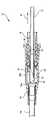
図1を参照すると、血管アクセスシステム10は、針12と、カテーテルアダプタ14と、スリーブ16と、安全クリップ18を有することが示されている。針12は、管状軸ないし本体を有する皮下注射針と、針12の遠位端に向かって配置された針特徴部20を含むことができる。針特徴部20は、安全クリップ18と相互作用するように設計されたフェルールないし干渉部を有することができる(詳細は後述する)。具体的な実施形態において、針12は皮下注射針であり、針特徴部20はフェルールである。針特徴部20は針12に沿って配置され、針12を針シールドアセンブリ10から抜いている間に、針特徴部20と針先端22が安全クリップ18内に一緒に保持されるようになっている。 Referring to FIG. 1, the
針12は、針シールドアセンブリ10の半径方向における中央を、ほぼ水平な軸24に沿って延在し、安全クリップ18の中に直接格納される。安全クリップ18はほぼスリーブ16の内腔内に配置され、基底部26と少なくとも1つのアーム28を有している。アーム28は基底部26から延び、針12にほぼ平行なものである。フラップ30はアーム28の遠位端から内側に向かって延在し、フラップ30は、針12の軸と接触した状態に保たれる。フラップ30は、針先端22と相互作用してこれを収容するのに有効などのような構造であってもよい。たとえば、一実施形態のフラップ30は、フラップ30の末端部分が安全クリップ18の基底部26に向かってカールするような構造である。別の実施形態では、安全クリップ基底部26は、2つのアーム28,28aを有するものであり、各アーム28,28aは、フラップを備える。第一のアーム28の第一のフラップ30は、内側にカールする末端部を有する。第二のアーム28aの第二のフラップ30aは、内側または外側にカールする末端部を有する。第一と第二のアーム28,28aは、第一のアーム28が第二のアーム28aより短くなるように構成される。したがって、第二のフラップ30aは、針先端22が安全クリップ18のフラップ30,30aを越えて引き戻されるとき、第一のフラップ30に重なるように配置することができる。 The
安全クリップ18の基底部26はさらに、少なくとも1つのかかり32を備える。かかり32は、基底部26の外表面に配置され、また、スリーブ16の内表面に配置されてスリーブ16の近位端に向いたかかり受け部34と適合した状態で係合するよう構成されている。安全クリップ18の基底部26はさらに、基底部26の近位端にカニューレ出入り口38をさらに備える。カニューレ出入り口38の内径は針12の軸の外径より若干大きいため、針12はカニューレ出入り口38を通ってスライド可能に移動できる。しかしながら、カニューレ出入り口38の内径は針特徴部20の外径より若干小さいため、針特徴部20はカニューレ出入り口38を通過できない。 The
安全クリップ18は、スリーブ16の内腔内に部分的に格納される。たとえば、基底部26は完全にスリーブ16の中に格納され、アーム28は一部がスリーブ16の中に格納され、フラップ30は完全にスリーブ16の中に入っていない。スリーブ16は概して管状であり、内腔を有し、その中に安全クリップ18の一部が格納される。スリーブ16の外径は、カテーテルアダプタ14の内径より若干小さくなるように選択されている。したがって、スリーブ16はカテーテルアダプタ14の内腔内に挿入することができる。スリーブ16はさらに、第一の端と第二の端を有し、第一の端にカニューレ出入り口36がある。カニューレ出入り口36の内径は針12の軸の外径より若干大きい。したがって、針12はカニューレ出入り口36を通ってスライド可能に移動できる。しかしながら、カニューレ出入り口36の内径は安全クリップ基底部26の外径より小さい。そのため、安全クリップ18の基底部26は、カニューレ出入り口36を通過して移動できず、スリーブ16の中に保持される。スリーブ16の第二の端は概して開いており、針12と安全クリップ18の少なくとも1つのアーム28は、スリーブ16の第二の端を超えて、カテーテルアダプタ14の内腔へと延在する。
スリーブ16はさらに、スリーブ16の第一の端の付近に、スリーブ16の内表面に設けられたかかり受け部34を備える。かかり受け部34は陥凹溝を有し、その幅と深さは、安全クリップのかかり32を適合した状態で受けるように設計されている。安全クリップ18の基底部26は、かかり32とスリーブ16の内表面との間の耐性をできるだけ小さくするよう構成され、これにより、スリーブ16の内表面がかかり32を内側に付勢するようにしている。安全クリップ18の基底部26がスリーブ16の第一の端に向かって引かれると、かかり32はかかり受け部34へと引き込まれる。このとき、かかり32の内側への付勢が解除されて、かかり32が外側に弛緩し、かかり受け部と係合する。いったん係合すると、かかり32とかかり受け部34が一方向にしか適合しないため、安全クリップ18はスリーブ16の第二の端の開口部から出ることができない。 The
スリーブ16はさらに、スリーブ16にヒンジ式に取り付けられた、スリーブ16の付属物としての嵌合フランジ40を備えることができる。一実施形態において、嵌合フランジ40は、スリーブ16の、3つの辺が完全に切り離された一部分であり、したがって、嵌合フランジ40はスリーブ16の、ヒンジ式に取り付けられた窓を形成する。嵌合フランジ40はどのような長さでもよいため、スリーブ16とカテーテルアダプタ14を嵌合させる機能を果たすのに必要な、スリーブ16の中のどの部分であってもよい。 The
嵌合フランジ40は、スリーブ16の外部材料の一部を除去して、スリーブ16と嵌合フランジ40の間に陥凹部を作ることによって形成されるヒンジ42を有する。ヒンジ42はスリーブの外表面に形成されているため、嵌合フランジ40は、ほぼ水平な軸24に関して外側に付勢されようにすることができる。嵌合フランジ40はさらに嵌合指状部44を有し、これは嵌合フランジ40のヒンジで取り付けられていない端の、嵌合フランジ40の外表面に配置される。嵌合指状部44は概して傾斜した形状を有し、カテーテルアダプタ14の内表面52に形成された嵌合対応部50と適合した状態で係合するように構成されている。嵌合指状部44は、嵌合フランジ40の外表面から半径方向外側に延在するため、スリーブ16の外表面より外側にも延在する。 The
最後に、嵌合フランジ40は安全クリップ接触部46を、嵌合フランジ40のヒンジで取り付けられていない端に備える。安全クリップ接触部46は、嵌合フランジ40の内表面の嵌合指状部44と反対側に位置づけられる。安全クリップ接触部46は嵌合フランジ40の内側に向かう延長部であり、安全クリップ18のアーム28aと接触して、これを挟むようになっている。したがって、嵌合フランジ40は、安全クリップ18の、挟んでいるアーム28aによって外側に付勢される。嵌合フランジ40が外側に付勢されることによって、嵌合指状部44は嵌合対応部50の中に確実に固定され、スリーブ16とカテーテルアダプタ14は互いにかみ合うことができる。 Finally, the
カテーテルアダプタ14は、ほぼ管状で、第一の端に開口部を有し、第一の端はスリーブ16を支持するよう構成され、この場合に、カテーテルアダプタ14の第一の端の内径がスリーブ16の外径より若干大きくされている。カテーテルアダプタはさらに、カテーテル54の格納部を形成する第二の端を有する。カテーテル54は、第一の端と第二の端を有する柔軟な管を有し、第一の端はカテーテルアダプタ14の第二の端の開口部の中に格納される。カテーテル54の第一の端は、針12と針特徴部20を受けるよう構成された開口部を有する。カテーテル54の第一の端は、カテーテルアダプタ14の第二の端の開口部内に液密状態で固定される。カテーテル54の第二の端は、針先端22がカテーテル54から先へと延びることができるようになされた開口部を有する。カテーテル54の第二の端の外表面は、針先端22に向かってテーパがつけられており、これによってカテーテル54を患者に挿入しやすくなる。 The
一実施形態において、スリーブ16の第二の端はカテーテルアダプタ14の中に格納される。スリーブ16は、外側に付勢された嵌合フランジ40の嵌合指状部44が嵌合対応部50と係合することによって、カテーテル14の内部に固定される。この同じ実施形態において、嵌合フランジ40は、安全クリップ接触部46と安全クリップアーム28aの挟むような相互作用によって、外側に付勢される。安全クリップアーム28aは、フラップ30aと針12の軸の挟むような相互作用によって、外側に付勢される。 In one embodiment, the second end of the
次に、図2−図5を参照すると、カテーテル54を患者(図示せず)に挿入した後の針シールドアセンブリ10が示されており、針12がカテーテル54から近位方向60に引き抜かれている。図2を参照すると、針12が近位方向60に向かって引き抜かれる際、針特徴部20は第一のフラップ30aと第二のフラップ30の下(内側)を通過する。このとき、第一のアーム28aと第二のアーム28は、針特徴部20が通過できるようにさらに外側に付勢されている。図3を参照すると、針12が引き続き近位方向60に引き抜かれると、針先端22は、第一のフラップ30aを越えて引き抜かれる。このとき、第一のフラップ30aは半径方向に内側へと弛緩し、これにより、第一のフラップ30aはもはや針12の軸を挟んでいない状態となる。この位置で、第一のフラップ30aは、針先端22が近位方向60と反対方向に移動して、第一のフラップ30aより先に出るのを防止する障害物として機能する。針12がさらに近位方向60に引き抜かれると、針先端22は第一のフラップ30を通過する。このとき、第二のフラップ30は半径方向に内側に弛緩し、これにより、第二のフラップ30はもはや針12の軸を挟んでいない状態となる。この位置で、第二のフラップ30は、針先端22が近位方向60と反対方向に移動して、第二のフラップ30より先に出るのを防止する障害物として機能する。 2-5, the
このとき、針12と針特徴部20は安全クリップ18の内腔の中に完全に入っている。したがって、針特徴部20は安全クリップ18のカニューレ出入り口38に当たって配置されている。この位置で、針特徴部20は、カニューレ出入り口38の直径が針特徴部20の外径より小さいために、カニューレ出入り口38を越えて移動できない。したがって、針12が近位方向60に引き抜かれると、針特徴部20はカニューレ出入り口38に引っ掛かり、安全クリップ18は針12および針特徴部20とともに近位方向60に移動する。 At this time, the
図4を参照すると、安全クリップ18は針12とともに近位方向60に移動し、最終的に第二のフラップ30が近位方向に移動して第一の安全クリップ接触部46を越える。このとき、第一の安全クリップ接触部46は第一のアーム28aと接触しなくなり、第一の嵌合フランジ40が内側に弛緩して、第一の嵌合指状部44がカテーテルアダプタ14の各々の嵌合対応部50から外れる。安全クリップ18がさらに移動すると、第一のフラップ30aは近位方向に移動して第二の安全クリップ接触部46aを通過する。このとき、第二の安全クリップ接触部46aは第二のアーム28と接触しなくなり、第二の嵌合フランジ40aが内側に弛緩して、第二の嵌合指状部44aはカテーテルアダプタ14の各々の嵌合対応部50から外れる。この時点で、かかり32はかかり受け部34と不可逆的に係合し、安全クリップ18はスリーブ16の中に固定される。さらに、この固定された位置において、安全クリップ基底部26はスリーブ16のカニューレ出入り口36と当接する。したがって、より大きな外径を持つ安全クリップ基底部26はより小さな直径のカニューレ出入り口36を通過できないため、安全クリップ18はそれ以上、近位方向60に移動できなくなる。 Referring to FIG. 4, the
次に、図5を参照すると、安全クリップ18はスリーブ16の内腔の中に固定され、スリーブ16はカテーテルアダプタ14と嵌合していない。したがって、嵌合指状部44,44aが両方とも各々の嵌合対応部50から外れ、針が近位方向60にさらに移動すると、解放されているスリーブ16はカテーテルアダプタ14の内腔から引き抜かれる。この地点で、針先端22は安全クリップ18の中に確実に固定されており、スリーブ16を血管アクセスシステム10から引き抜いて、処分できる。 Referring now to FIG. 5, the
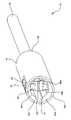
図6を参照すると、スリーブ70と安全クリップ72の実施形態が示されている。安全クリップ72の基底部74は一対の位置合わせクリップ76を有するように改変されており、この位置合わせクリップは、スリーブ70内での安全クリップ72の適正位置を制御する。安全クリップ72は、基底部74と、少なくとも1つのアーム80と、少なくとも1つのフラップ82と、カニューレ出入り口84と、かかり32と、1対の位置合わせクリップ76を有する。基底部74はほぼ管状であり、第一の端はカニューレ出入り口84を有し、第二の端は概して開放している。基底部74はさらに、基底部74の第二の端から横方向に延びる少なくとも1つのアーム80を有する。アーム80は基底部からほぼ水平な軸24に沿って延在し、フラップ82に続く。基底部74はさらに、かかり32を有する。かかり32は、基底部74の、部分的に切り抜かれた、折り返し部であり、かかり32の3辺は基底部74に取り付けられず、第4の辺が基底部74に取り付けられている。かかり32は外側に付勢され、かかり32は基底部74の第二の端に向いて開いている。したがって、かかり32の、取り付けられていない端は、スリーブ70のかかり受け部と不可逆的に係合する。 Referring to FIG. 6, an embodiment of a
各位置合わせクリップ76は、基底部74を一部切り抜き、折り返される部分からなる。各位置合わせクリップ76は、外側に向かって付勢され、各位置合わせクリップ76の自由端86がカニューレ出入り口84に向いて開いている。各位置合わせクリップ76の自由端は、スリーブ70の位置合わせ溝78との相互作用によって、スリーブ70に関する安全クリップ72の回転を防止する。したがって、位置合わせクリップ76によって、かかり32とかかり受け部が正しい位置関係となる。さらに、位置合わせクリップ76により、アーム80とスリーブ70の安全クリップ接触部46とが確実に正しい位置関係となる。 Each
スリーブ70は概して管状であり、第一の端96と第二の端102の両方に開口部を有する。スリーブ70はさらに、第一の内径90と第二の内径100を有する。第一の内径90は安全クリップ基底部74の外径98とほぼ等しいため、安全クリップ72はスリーブ70の中にスライド可能に格納される。スリーブ70はさらに、スリーブ70の内表面92の陥凹溝を有した一対の位置合わせ溝78を有する。位置合わせ溝78は、位置合わせクリップ76が位置合わせ溝78の中で移動できるように選択された溝の深さと溝の幅によって画定される。位置合わせ溝78は第一の端62と第二の端64を有し、第一の端62には開口部、第二の端64にはクリップ受け部94がある。クリップ受け部94は位置合わせ溝78を閉じ、位置合わせ溝78はスリーブ70の第一の端96の前の地点で終わる。クリップ受け部94は、各位置合わせクリップ76の自由端86と相互作用して、安全クリップ72がスリーブ70の第一の端96から出るのを防止する。クリップ受け部94の位置は、位置合わせクリップ76とクリップ受け部94、かかり32とかかり受け部34が同時に相互作用するように選択される。そのため、安全クリップ72がスリーブ70の第一の端96に向かって引き抜かれると、両方の相互作用が同時に発生し、安全クリップ72はスリーブ70内の所定の位置に固定される。 The
スリーブ70はさらに、スリーブ70の第二の端102に位置する第二の内径100を有する。第二の内径100は第一の内径90より大きく、スリーブ70の内表面92は、第一の内径90から第二の内径100へとテーパがつけられている。したがって、内表面92のテーパ部分により、アーム80とフラップ82がスリーブ70の第二の端102を越えた時に、安全クリップアーム80が外側に付勢されるための間隙が設けられる。スリーブはさらに、一対の嵌合フランジ40を有する。各嵌合フランジ40は、前の実施形態で説明したように(図1−図5参照)、嵌合指状部44と安全クリップ接触部46を有する。 The
次に、図7を参照すると、針シールドアセンブリ10は、スリーブ70がカテーテルアダプタ14から外された状態で示されている。図のように、針12と安全クリップフラップ82,82aは、スリーブ70の内腔の中に引き込まれている。第一と第二のフラップ82,82aは閉鎖位置にあり、針先端22は安全クリップ内に取り囲まれる。嵌合フランジ40は内側に弛緩しているため、嵌合指状部44はカテーテルアダプタ14の嵌合対応部から外れている。安全クリップ接触部46,46aは安全クリップフラップ82,82aの前に位置づけられ、これによって、より確実に安全クリップがスリーブ70の中に格納される。 Referring now to FIG. 7, the
次に、図8−図10を参照すると、針シールドアセンブリ110が示されている。針シールドアセンブリ110は、針12と、カテーテルアダプタ112と、スリーブ114と、安全クリップ116を有するものである。この実施形態において、安全クリップ116は少なくとも1つのアーム134を有するように改変されており、アーム134の遠位端には嵌合フランジ130がある。嵌合フランジ130は、嵌合フランジ130の遠位端140から内側に延びるフラップ138を有する。この位置において、フラップ138の自由端142は、針12の軸を挟み、針12の外表面144に弱い圧力を作用する。したがって、針12の存在によって、嵌合フランジ130は外側に付勢される。嵌合フランジ130はさらに、嵌合フランジ130の遠位端140から外側に延在する嵌合指状部132を有する。嵌合指状部132はフラップ138とほぼ反対の方向に位置付けけられ、嵌合指状部132は嵌合リング118の内表面との境界面146を形成する。フラップ138は線形であっても、あるいは高低を付けて、針先端22を有効にシールドして保持するだけでなく、針12の使用後に針先端22から残留液体が浸潤するのを受けるように構成されていてもよい。 Referring now to FIGS. 8-10, the
カテーテルアダプタ112は、嵌合リング118を有する。嵌合リング118は、カテーテルアダプタ112の第一の端122の開口部に配置され、カテーテルアダプタ112の内表面120の、内側に向かう環状の延長部を有する。嵌合リング118の深さと幅は、嵌合フランジ130の嵌合指状部132と係合するための適合面が提供されるように選択される。嵌合フランジ130は、針12の存在によって外側に付勢され、針12がフラップ138の自由端142によって挟まれるため、嵌合フランジ130は外側へと変位する。したがって、嵌合指状部132は嵌合リング118と係合して、嵌合指状部132と嵌合リング118の間の境界面146を形成する。このように、カテーテルアダプタ112とスリーブ114は、境界面によって支持され、相互にロックされる。 The
スリーブ114は、スリーブ114の内表面152に形成された少なくとも1つの嵌合指状部移動溝150を有するように改造されている。嵌合指状部移動溝150は、スリーブ114の内表面152に形成された陥凹溝である。嵌合指状部移動溝150は、スリーブ114の遠位端154からスリーブ114の近位端156にかけて延在し、嵌合指状部受け部158で終わる。嵌合指状部受け部158は、嵌合指状部移動溝150の終端であり、スリーブ114の近位端156の前に配置される。嵌合指状部移動溝150は、安全クリップ116の嵌合指状部132を適合した状態で受けるように構成される。嵌合指状部132は嵌合指状部移動溝150内を、スリーブ114の遠位端154からスリーブ114の近位端156まで移動できる。1カ所において、嵌合指状部132は嵌合指状部受け部158と係合し、安全クリップ116がそれ以上スリーブ114の中に入らないようにされる。嵌合指状部受け部158の位置は、嵌合指状部132と嵌合指状部受け部158および、かかり32とかかり受け部34とが同時に相互作用するように選択される。したがって、安全クリップ116がスリーブ114の近位端156の方向に引かれると、両方の相互作用が同時に発生し、安全クリップ116がスリーブ114の中の所定の位置に固定される。 The
スリーブ114はさらに、スリーブ114の内表面152と安全クリップ116のかかり32の間の耐性が最小限となるように改変されている。したがって、かかり32は、スリーブ114の内面152と接触した状態に保たれる。かかり32とスリーブ114の内面152との相互作用によって、安全クリップ116はスリーブ114の遠位端154に向かって移動できず、またここから出ることができない。そのため、安全クリップ116は、スリーブ114の近位端156の方向にのみ移動し、ここから出ることができる。安全クリップが一方向にしか移動できないことから、スリーブ114とカテーテルアダプタ112はさらに確実に固定されることになり、境界面146への干渉がなくなる。 The
嵌合指状部移動溝150と嵌合指状部132が係合することにより、安全クリップ116はスリーブ114の内部で半径方向に正しく位置合わせされるようにすることもできる。スリーブ114の遠位端154は、テーパのついた開口部160を提供するようにさらに改変されている。テーパのついた開口部160によって、嵌合フランジ130が外側に付勢されるための間隙が得られる。したがって、嵌合フランジ130は、スリーブ114の内表面152に接触したり、旋回したりすることなく、外側に付勢される。 The engagement clip-shaped
針シールドアセンブリ110は、カテーテル54を患者に挿入した後に作動する。カテーテル挿入後、針12はカテーテル54から近位方向60に外される。針12が外される際、針特徴部20は第一と第二のフラップ138の下(内側)を通過する。第一と第二の嵌合フランジ130は、針特徴部20の通過によってさらに外へと付勢される。針12が引き続き近位方向60に移動すると、針先端22は、第一と第二のフラップ138を通過して引き抜かれる。このとき、第一と第二の嵌合フランジ130は内側に弛緩して、針先端22をシールドする。さらに、嵌合フランジ130が内側に弛緩することによって、第一と第二の嵌合指状部132は嵌合リング118から解放される。そのため、嵌合指状部132は嵌合リング118から外れ、スリーブ14とカテーテルアダプタ112は接続されていない状態となる。
この時点で、針特徴部20は安全クリップ116のカニューレ出入り口84と当接する。したがって、より大きな直径の針特徴部20は、近位方向60に移動して、より小さな直径カニューレ出入り口84を超えることができない。そのため、針12が近位方向60に引き込まれると、針特徴部20はカニューレ出入り口84とひっかかり、安全クリップ116は針12とともに近位方向60に移動する。 At this point, the
針12と安全クリップ116が近位方向60に移動すると、嵌合指状部132は嵌合溝150と係合する。この状態で、嵌合指状部132は嵌合溝150の中で近位方向60に移動する。嵌合指状部132は、嵌合指状部132が嵌合指状部受け部158と接触するまで、嵌合溝150の中を移動する。この時点で、安全クリップ116とその中に格納された針12は、それ以上近位方向60に移動できない。嵌合指状部132が嵌合溝150の中を移動すると、スリーブ114のテーパ付開口部160がフラップ138を内側に付勢する。したがって、フラップ138は、針先端22の前で相互に重複して閉鎖するような位置に移動する。この位置で、フラップ138は針先端22をシールドし、針先端22を安全クリップ116の中にさらに確実に格納する。 As the
フラップ138が閉じ、針先端22をシールドした状態で、安全クリップ116は引き続き近位方向60に移動し、嵌合指状部132が嵌合溝150の嵌合指状部受け部158と接触したところで止まる。この接触と同時に、かかり32はそれぞれのかかり受け部34と係合し、それによって、安全クリップ116とその中に格納された針先端22はスリーブ114の内腔に固定される。 With the
本発明の針シールドアセンブリには、同じ発明的アイディアの中で、多数の変更を加えることが可能である。たとえば、針シールドアセンブリは、IVカテーテルのかニューレ、長い麻酔針の形状、カテーテルアダプタおよびその他これらの医療器材に用いるカニューレの先端の保護に使用することができる。針シールドアセンブリおよび/または管状ハウジングの断面は、正方形、長方形、三角形、長円、多角形等、他の形状であってもよい。針特徴部は非対称でもよく、軸に取り付ける、またはフェルールに取り付ける形態以外であってもよい。嵌合や嵌合対応部を提供するには、どのような構造を利用してもよい。針シールドには、1つまたは複数の血液安定化材を設け、さらに血液曝露のリスクを制限してもよい。血液安定化材料は、スリーブ、安全クリップおよび/または針シールドアセンブリの1つまたは複数の内面または外面に配置してもよい。上記に加え、または上記の代わりに、血液安定化材は、針が密着して通過する通路を有する、固体または半固体リングとして組み込んでもよい。血液安定化材は、凝固剤、吸収材、または曝露リスクを減らすために血液を安定化させるその他のどの材料であってもよい。同様に、血液安定化材は、液体、固体、ゲル、粉末、顆粒またはその他その使用に適したどのような堅さであってもよい。血液安定化材は、血液は進入できるが、血液安定化材は漏出できない、多孔質膜または容器の中に入れてもよい。さらに、上記の実施形態の要素は、あらゆる実施形態の他の要素と、数、方向を取らず、組み合わせることができる。 Many modifications can be made to the needle shield assembly of the present invention within the same inventive idea. For example, the needle shield assembly can be used to protect the tip of a cannula used in IV catheter burrows, long anesthetic needle shapes, catheter adapters, and other medical devices. The cross-section of the needle shield assembly and / or tubular housing may be other shapes such as square, rectangular, triangular, oval, polygonal, etc. The needle feature may be asymmetrical and may be other than attached to the shaft or attached to the ferrule. Any structure may be used to provide the fitting or the fitting counterpart. The needle shield may be provided with one or more blood stabilizers to further limit the risk of blood exposure. The blood stabilizing material may be disposed on one or more inner or outer surfaces of the sleeve, safety clip and / or needle shield assembly. In addition to or in lieu of the above, the blood stabilizing material may be incorporated as a solid or semi-solid ring having a passage through which the needle passes. The blood stabilizing material can be a coagulant, an absorbent material, or any other material that stabilizes the blood to reduce exposure risk. Similarly, the blood stabilizing material may be liquid, solid, gel, powder, granule or any other hardness suitable for its use. The blood stabilizing material may be placed in a porous membrane or container that allows blood to enter, but not blood leakage. Furthermore, the elements of the above embodiments can be combined with other elements of any embodiment without taking a number and direction.
本発明は、本明細書で幅広く説明され、後に請求されるその構造、方法その他の基本的特徴から逸脱することなく、他の具体的な形態でも実施できる。紹介した実施形態は、あらゆる点において限定的ではなく、例示として考えるものとする。したがって、本発明の範囲は、上記の説明ではなく、付属の特許請求範囲により示される。特許請求範囲の等価物の意味と範囲内に入るすべての変更は、その範囲内に包含されるものとする。 The present invention may be embodied in other specific forms without departing from the structure, method, or other basic features described broadly herein and claimed later. The introduced embodiments are not to be considered limiting in all respects and are to be considered as illustrative. The scope of the invention is, therefore, indicated by the appended claims rather than by the foregoing description. All changes that come within the meaning and range of equivalency of the claims are to be embraced within their scope.
Claims (16)
Translated fromJapaneseカテーテルアダプタと組み合わされたスリーブと、
部分的に前記スリーブ内に格納され、また部分的に前記カテーテルアダプタ内に格納される安全クリップであって、前記安全クリップの一部が前記スリーブから遠位方向に延在し、前記スリーブから遠位方向に延在する安全クリップの一部が前記スリーブに力を作用して前記スリーブの嵌合フランジが外側に付勢されて前記カテーテルアダプタの嵌合対応部の中に入り、それによって、前記安全クリップが前記スリーブから遠位方向に延在する間、前記スリーブを前記カテーテルアダプタに固定するようにした安全クリップと、
前記スリーブ、前記カテーテルアダプタ、および前記安全クリップ内に延在する針と、
を備え、
前記針を前記装置の前記近位端から引き抜いたときに、前記安全クリップが前記スリーブ内に保持される間、前記針の先端は前記安全クリップ内に保持されて、前記安全クリップから再び出ることが防止されることを特徴とする装置。A device for shielding the tip of a needle,
A sleeve combined with a catheter adapter;
A safety clip partially stored within the sleeve and partially stored within the catheter adapter, wherein a portion of the safety clip extends distally from the sleeve and is remote from the sleeve. A portion of the laterally extending safety clip exerts a force on the sleeve and the mating flange of the sleeve is biased outwardly into the mating counterpart of the catheter adapter, thereby A safety clip adapted to secure the sleeve to the catheter adapter while the safety clip extends distally from the sleeve ;
The sleeve, the catheter adapter, anda needle extendinginto the safety clip;
With
When the needle is withdrawn from the proximal end of the device, the tip of the needle is retained within the safety clip and exits the safety clip againwhile the safety clip is retained within the sleeve. A device characterized in that is prevented.
スリーブとカテーテルアダプタを組み合わせるステップと、
安全クリップを部分的に前記スリーブ内に、また部分的に前記カテーテルアダプタ内に格納し、前記安全クリップの一部が前記スリーブから遠位方向に延在し、前記スリーブから遠位方向に延在する安全クリップの一部が前記スリーブに力を作用して前記スリーブの嵌合フランジが外側に付勢されて前記カテーテルアダプタの嵌合対応部の中に入り、それによって、前記安全クリップが前記スリーブから遠位方向に延在する間、前記スリーブを前記カテーテルアダプタに固定するようにするステップと、
前記針を前記スリーブ、前記カテーテルアダプタおよび前記安全クリップの中に延在させるステップと、
を有し、
前記針を前記カテーテルアダプタの前記近位端から引き抜くと、前記安全クリップが前記スリーブ内に保持される間、前記針の先端が前記安全クリップ内に保持され、前記安全クリップから再び出ることが防止されることを特徴とする方法。A method of holding the tip of a needle,
Combining the sleeve and catheter adapter;
A safety clip is partially stored within the sleeve and partially within the catheter adapter,a portion of the safety clip extending distally from the sleeve and extending distally from the sleeve A portion of the safety clip that exerts a force on the sleeve and biases the mating flange of the sleeve outwardly into the mating counterpart of the catheter adapter so that the safety clip is in the sleeve Securing the sleeve to the catheter adapter while extending distally from the catheter ;
Said sleeve said needle, a stepcausing extends into the catheter adapter and the safety clip,
Have
When the needle is withdrawn from the proximal end of the catheter adapter, the tip of the needleis retained within the safety clip while the safety clip is retained within the sleeve, preventing it from exiting the safety clip again. A method characterized by being made.
カテーテルアダプタと組み合わされたスリーブと、
部分的に前記スリーブ内に格納され、部分的に前記カテーテルアダプタ内に格納される安全クリップであって、前記安全クリップの一部が前記スリーブから遠位方向に延在し、前記スリーブから遠位方向に延在する安全クリップの一部が前記スリーブに力を作用して前記スリーブの嵌合フランジが外側に付勢されて前記カテーテルアダプタの嵌合対応部の中に入り、それによって、前記安全クリップが前記スリーブから遠位方向に延在する間、前記スリーブを前記カテーテルアダプタに固定するようにした安全クリップと、
前記スリーブ、前記カテーテルアダプタ、および前記安全クリップ内に延在し、前記針の先端が前記カテーテルアダプタの近位端で露出するようになされた針と、
を備え、
前記針を前記カテーテルアダプタの前記近位端から引き抜くとき、前記安全クリップが前記スリーブ内に保持される間、前記針の先端は前記安全クリップ内に保持され、前記安全クリップから再び出ることが防止されることを特徴とする装置。A device that shields the tip of a needle after placement of a catheter in a patient,
A sleeve combined with a catheter adapter;
A safety clip partially stored within the sleeve and partially stored within the catheter adapter,wherein a portion of the safety clip extends distally from the sleeve and is distal from the sleeve A portion of the safety clip extending in a direction exerts a force on the sleeve and the mating flange of the sleeve is urged outwardly into the mating counterpart of the catheter adapter, whereby the safety clip A safety clipadapted to secure the sleeve to the catheter adapter while the clip extends distally from the sleeve ;
A needle extending into the sleeve, the catheter adapter, and the safety clip such that a tip of the needle is exposed at a proximal end of the catheter adapter;
With
When the needle is withdrawn from the proximal end of the catheter adapter, the tip of the needleis retained in the safety clip while the safety clip is retained in the sleeve, preventing it from coming out of the safety clip again. The apparatus characterized by being made.
Applications Claiming Priority (3)
| Application Number | Priority Date | Filing Date | Title |
|---|---|---|---|
| US12/119,332US7828774B2 (en) | 2008-05-12 | 2008-05-12 | Sleeved clip safety |
| US12/119,332 | 2008-05-12 | ||
| PCT/US2009/036828WO2009139951A1 (en) | 2008-05-12 | 2009-03-11 | Sleeved clip safety |
Publications (2)
| Publication Number | Publication Date |
|---|---|
| JP2011519707A JP2011519707A (en) | 2011-07-14 |
| JP5497747B2true JP5497747B2 (en) | 2014-05-21 |
Family
ID=40758933
Family Applications (1)
| Application Number | Title | Priority Date | Filing Date |
|---|---|---|---|
| JP2011509503AActiveJP5497747B2 (en) | 2008-05-12 | 2009-03-11 | Clip safety device with sleeve |
Country Status (10)
| Country | Link |
|---|---|
| US (1) | US7828774B2 (en) |
| EP (1) | EP2282799B1 (en) |
| JP (1) | JP5497747B2 (en) |
| AU (1) | AU2009246802B2 (en) |
| BR (1) | BRPI0911964B8 (en) |
| CA (1) | CA2723732C (en) |
| ES (1) | ES2558936T3 (en) |
| MX (1) | MX2010012284A (en) |
| NZ (1) | NZ589234A (en) |
| WO (1) | WO2009139951A1 (en) |
Families Citing this family (90)
| Publication number | Priority date | Publication date | Assignee | Title |
|---|---|---|---|---|
| US8066678B2 (en)* | 2001-12-17 | 2011-11-29 | Bard Access Systems, Inc. | Safety needle with collapsible sheath |
| US7776016B1 (en) | 2004-02-26 | 2010-08-17 | C. R. Bard, Inc. | Huber needle safety enclosure |
| EP1907042B1 (en) | 2005-07-06 | 2009-03-11 | Vascular Pathways Inc. | Intravenous catheter insertion device and method of use |
| JP4994775B2 (en) | 2006-10-12 | 2012-08-08 | 日本コヴィディエン株式会社 | Needle point protector |
| US8597253B2 (en) | 2007-04-20 | 2013-12-03 | Bard Access Systems | Huber needle with safety sheath |
| EP2150304B1 (en) | 2007-05-07 | 2010-12-01 | Vascular Pathways Inc. | Intravenous catheter insertion and blood sample devices and method of use |
| WO2009042874A1 (en)* | 2007-09-27 | 2009-04-02 | Tyco Healthcare Group Lp | I.v. catheter assembly and needle safety device |
| US8231582B2 (en) | 2008-12-11 | 2012-07-31 | Bard Access Systems, Inc. | Device for removing a Huber needle from a patient |
| US9399120B2 (en)* | 2009-03-02 | 2016-07-26 | Becton, Dickinson And Company | Bi-directional cannula feature capture mechanism |
| US8936575B2 (en)* | 2009-03-19 | 2015-01-20 | Becton, Dickinson And Company | Cannula-tip shielding mechanism |
| US11925779B2 (en) | 2010-05-14 | 2024-03-12 | C. R. Bard, Inc. | Catheter insertion device including top-mounted advancement components |
| US8932258B2 (en) | 2010-05-14 | 2015-01-13 | C. R. Bard, Inc. | Catheter placement device and method |
| US9950139B2 (en) | 2010-05-14 | 2018-04-24 | C. R. Bard, Inc. | Catheter placement device including guidewire and catheter control elements |
| US10384039B2 (en) | 2010-05-14 | 2019-08-20 | C. R. Bard, Inc. | Catheter insertion device including top-mounted advancement components |
| US9872971B2 (en) | 2010-05-14 | 2018-01-23 | C. R. Bard, Inc. | Guidewire extension system for a catheter placement device |
| US8257322B2 (en)* | 2010-06-02 | 2012-09-04 | Smiths Medical Asd, Inc. | Tip protector for a safety catheter |
| RU2729036C2 (en)* | 2010-08-05 | 2020-08-03 | Б. Браун Мельзунген Аг | Safe needle device and assembly |
| US20140066894A1 (en) | 2010-09-10 | 2014-03-06 | C. R. Bard, Inc. | Self-Sealing Pad for a Needle-Based Infusion Set |
| US10525234B2 (en) | 2010-09-10 | 2020-01-07 | C. R. Bard, Inc. | Antimicrobial/haemostatic interface pad for placement between percutaneously placed medical device and patient skin |
| EP2613824A1 (en) | 2010-09-10 | 2013-07-17 | C.R. Bard Inc. | Systems for isolation of a needle-based infusion set |
| ES2725777T3 (en)* | 2010-12-02 | 2019-09-27 | Erskine Medical Llc | Release mechanism for use with needle protection devices |
| MY161281A (en) | 2010-12-02 | 2017-04-14 | Erskine Medical Llc | Needle shield assembly with hub engagement member for needle device |
| US8690833B2 (en) | 2011-01-31 | 2014-04-08 | Vascular Pathways, Inc. | Intravenous catheter and insertion device with reduced blood spatter |
| ES2835652T3 (en) | 2011-02-25 | 2021-06-22 | Bard Inc C R | Medical component insertion device including a retractable needle |
| US9238104B2 (en) | 2011-02-28 | 2016-01-19 | Injectimed, Inc. | Needle guard |
| US8764711B2 (en) | 2011-02-28 | 2014-07-01 | Injectimed, Inc. | Needle guard |
| WO2012139034A1 (en) | 2011-04-07 | 2012-10-11 | Erskine Medical Llc | Needle shielding device |
| ES2662356T3 (en) | 2011-04-27 | 2018-04-06 | Kpr U.S., Llc | Safety IV catheter assemblies |
| USD903101S1 (en) | 2011-05-13 | 2020-11-24 | C. R. Bard, Inc. | Catheter |
| US8591467B2 (en) | 2011-07-25 | 2013-11-26 | Covidien Lp | Vascular access assembly and safety device |
| EP2736576B1 (en) | 2011-07-26 | 2020-07-01 | Poly Medicure Limited | Needle tip protector assembly for safety iv catheter assembly |
| WO2013048975A1 (en) | 2011-09-26 | 2013-04-04 | Covidien Lp | Safety catheter |
| EP2760521B1 (en) | 2011-09-26 | 2016-01-06 | Covidien LP | Safety iv catheter and needle assembly |
| US8834422B2 (en) | 2011-10-14 | 2014-09-16 | Covidien Lp | Vascular access assembly and safety device |
| US8746075B2 (en) | 2012-02-16 | 2014-06-10 | 7-Sigma, Inc. | Flexible electrically conductive nanotube sensor for elastomeric devices |
| CN103285449B (en)* | 2012-09-04 | 2015-02-25 | 上海普益医疗器械股份有限公司 | Puncture-proof indwelling needle |
| CN104684605B (en)* | 2012-10-05 | 2018-10-02 | 美德株式会社 | Safety needles for medical use to avoid needle point re-exposure |
| WO2014120741A1 (en) | 2013-01-30 | 2014-08-07 | Vascular Pathways, Inc. | Systems and methods for venipuncture and catheter placement |
| US11224724B2 (en) | 2013-03-12 | 2022-01-18 | Teleflex Medical Incorporated | Catheter insertion device |
| US10357635B2 (en) | 2013-03-12 | 2019-07-23 | Teleflex Medical Incorporated | Catheter insertion device |
| US9717886B2 (en) | 2013-03-12 | 2017-08-01 | Teleflex Medical Incorporated | Safety clip for a needle |
| US20140272870A1 (en)* | 2013-03-14 | 2014-09-18 | 7-Sigma, Inc. | Responsive model with sensors |
| US10500376B2 (en) | 2013-06-07 | 2019-12-10 | Becton, Dickinson And Company | IV catheter having external needle shield and internal blood control septum |
| AU2014287348B2 (en)* | 2013-07-11 | 2018-11-01 | Becton, Dickinson And Company | Bi-directional cannula feature capture mechanism |
| JP6247487B2 (en)* | 2013-09-25 | 2017-12-13 | 三菱鉛筆株式会社 | Puncture tool |
| US9555221B2 (en) | 2014-04-10 | 2017-01-31 | Smiths Medical Asd, Inc. | Constant force hold tip protector for a safety catheter |
| SG11201608547XA (en)* | 2014-04-18 | 2016-11-29 | Becton Dickinson Co | Needle capture safety interlock for catheter |
| WO2016037127A1 (en) | 2014-09-05 | 2016-03-10 | C.R. Bard, Inc. | Catheter insertion device including retractable needle |
| CN107249673B (en)* | 2014-11-10 | 2021-02-26 | 贝克顿·迪金森公司 | Safety IV Catheter with V-Clip Interlock and Needle End Capture |
| US11511052B2 (en) | 2014-11-10 | 2022-11-29 | Becton, Dickinson And Company | Safety IV catheter with V-clip interlock and needle tip capture |
| US20160220805A1 (en) | 2015-01-30 | 2016-08-04 | Smiths Medical Asd, Inc. | Intravenous catheter assembly design |
| JP6640861B2 (en) | 2015-01-30 | 2020-02-05 | スミスズ メディカル エーエスディー,インコーポレイティド | Releasable catheter hub retainer |
| USD765838S1 (en) | 2015-03-26 | 2016-09-06 | Tech Group Europe Limited | Syringe retention clip |
| USD903100S1 (en) | 2015-05-01 | 2020-11-24 | C. R. Bard, Inc. | Catheter placement device |
| CN113350614A (en) | 2015-05-15 | 2021-09-07 | C·R·巴德股份有限公司 | Catheter placement device including extendable needle safety feature |
| US10173002B2 (en)* | 2015-06-08 | 2019-01-08 | B. Braun Melsungen Ag | Catheter devices with needle guards and related methods |
| EP3131614B1 (en)* | 2015-06-27 | 2018-08-22 | Poly Medicure Limited | Intravenous catheter apparatus |
| US10195411B2 (en)* | 2015-07-16 | 2019-02-05 | Fresenius Medical Care Holdings, Inc. | Blood line sets with deformable blood lines |
| CN107050622A (en)* | 2015-12-01 | 2017-08-18 | B.布劳恩梅尔松根股份公司 | Needle device and correlation technique with bistable structure |
| DE102016108870A1 (en)* | 2016-05-13 | 2017-11-16 | Gerresheimer Regensburg Gmbh | Stinging agent protection device for a syringe |
| US11344220B2 (en) | 2016-05-13 | 2022-05-31 | Becton, Dickinson And Company | Invasive medical device cover with magnet |
| US10032552B2 (en)* | 2016-08-30 | 2018-07-24 | Becton, Dickinson And Company | Cover for tissue penetrating device with integrated magnets and magnetic shielding |
| US10493262B2 (en) | 2016-09-12 | 2019-12-03 | C. R. Bard, Inc. | Blood control for a catheter insertion device |
| EP3528723B1 (en) | 2016-10-27 | 2023-08-16 | C. R. Bard, Inc. | Intraosseous access device |
| EP3585471B1 (en) | 2017-03-01 | 2025-01-01 | C. R. Bard, Inc. | Catheter insertion device |
| US10946176B2 (en)* | 2017-04-06 | 2021-03-16 | Becton, Dickinson And Company | Intravenous catheter assembly with safety clip |
| EP4480525A3 (en) | 2017-04-13 | 2025-04-09 | Teleflex Medical Incorporated | Catheter insertion device |
| US10500375B2 (en) | 2017-07-31 | 2019-12-10 | Becton, Dickinson And Company | Catheter assembly |
| MY208028A (en)* | 2018-01-31 | 2025-04-08 | Icu Medical Inc | Releasable safety catheter insertion assembly |
| ES2980192T3 (en) | 2018-03-07 | 2024-09-30 | Bard Access Systems Inc | Guidewire advancement and blood reflux systems for a medical device insertion system |
| US11857320B2 (en) | 2018-06-08 | 2024-01-02 | Smiths Medical Asd, Inc. | Blood sequestration device and method |
| USD921884S1 (en) | 2018-07-27 | 2021-06-08 | Bard Access Systems, Inc. | Catheter insertion device |
| CA3151126A1 (en) | 2019-08-19 | 2021-02-25 | Becton, Dickinson And Company | Midline catheter placement device |
| CA3169051A1 (en) | 2019-09-10 | 2021-03-18 | Medsource International Llc | An intravenous catheter device |
| US11759235B2 (en) | 2019-09-27 | 2023-09-19 | Bard Access Systems, Inc. | Constant-torque intraosseous access devices and methods thereof |
| CN212879505U (en) | 2019-09-27 | 2021-04-06 | 巴德阿克塞斯系统股份有限公司 | Intraosseous access device |
| WO2021062215A1 (en) | 2019-09-27 | 2021-04-01 | Bard Access Systems, Inc. | Step needle for intraosseous access device |
| CN212879457U (en) | 2019-09-27 | 2021-04-06 | 巴德阿克塞斯系统股份有限公司 | Self-advancing intraosseous access device and intraosseous access device |
| US12279793B2 (en)* | 2019-10-16 | 2025-04-22 | Fresenius Kabi Deutschland Gmbh | Cannula device |
| CN113317840A (en) | 2020-02-28 | 2021-08-31 | 巴德阿克塞斯系统股份有限公司 | Flexible intra-osseous obturator |
| US12201791B2 (en)* | 2020-03-31 | 2025-01-21 | Becton, Dickinson And Company | Intravenous device assembly with needle guard |
| WO2021216521A1 (en) | 2020-04-21 | 2021-10-28 | Bard Access Systems , Inc. | Reusable push-activated intraosseous access device |
| CN113749724A (en) | 2020-06-03 | 2021-12-07 | 巴德阿克塞斯系统股份有限公司 | Intraosseous device including sensing obturator |
| US11980727B2 (en)* | 2020-06-10 | 2024-05-14 | Becton, Dickinson And Company | Needle protection device and related systems and methods |
| CN216167681U (en) | 2020-07-17 | 2022-04-05 | 巴德阿克塞斯系统股份有限公司 | Safety mechanism |
| CN216628654U (en) | 2020-08-25 | 2022-05-31 | 巴德阿克塞斯系统股份有限公司 | Angled intraosseous access system |
| CN215839325U (en) | 2020-09-09 | 2022-02-18 | 巴德阿克塞斯系统股份有限公司 | Suction device for an intraosseous access system |
| CN217960227U (en) | 2021-02-08 | 2022-12-06 | 巴德阿克塞斯系统股份有限公司 | Intraosseous access system |
| US12337123B2 (en) | 2021-05-06 | 2025-06-24 | Medsource Labs, Llc | Safety intravenous cannula |
| US12186497B2 (en) | 2022-01-14 | 2025-01-07 | Medsource International Llc | Intravenous cannula |
Family Cites Families (27)
| Publication number | Priority date | Publication date | Assignee | Title |
|---|---|---|---|---|
| US4964854A (en) | 1989-01-23 | 1990-10-23 | Luther Medical Products, Inc. | Intravascular catheter assembly incorporating needle tip shielding cap |
| US5558651A (en) | 1990-04-20 | 1996-09-24 | Becton Dickinson And Company | Apparatus and method for a needle tip cover |
| GB9120416D0 (en) | 1991-09-25 | 1991-11-06 | Sterimatic Holdings Ltd | Catheter placement units |
| US5215528C1 (en)* | 1992-02-07 | 2001-09-11 | Becton Dickinson Co | Catheter introducer assembly including needle tip shield |
| US5409461A (en) | 1993-09-28 | 1995-04-25 | Becton Dickinson And Company | Catheter introducer assembly with needle shielding device |
| US5599310A (en) | 1995-06-07 | 1997-02-04 | Johnson & Johnson Medical, Inc. | I.V. catheter assembly with automatic cannula tip guard |
| US5879337A (en) | 1997-02-27 | 1999-03-09 | Injectimed, Inc. | Needle tip guard for hypodermic needles |
| US8211070B2 (en) | 1997-08-20 | 2012-07-03 | B. Braun Melsungen Ag | Spring clip safety IV catheter |
| US6616630B1 (en) | 1997-08-20 | 2003-09-09 | B. Braun Melsungen A.G. | Spring clip safety IV catheter |
| DE20104539U1 (en)* | 2000-08-14 | 2001-12-20 | B. Braun Melsungen Ag, 34212 Melsungen | Intravenous catheter device |
| US6117108A (en) | 1997-08-20 | 2000-09-12 | Braun Melsungen Ag | Spring clip safety IV catheter |
| US6221047B1 (en) | 1998-07-31 | 2001-04-24 | Albany Medical College | Safety intravenous catheter assembly and method for use with a needle |
| US6224569B1 (en) | 1999-09-24 | 2001-05-01 | Becton, Dickinson And Company | Compact needle point shield |
| US6322537B1 (en) | 1999-12-30 | 2001-11-27 | Ethicon, Inc. | Safety intravenous catheter |
| US6692471B2 (en) | 2001-02-16 | 2004-02-17 | Medex, Inc. | Method and apparatus for safety catheter insertion device |
| DE20106697U1 (en)* | 2001-04-18 | 2001-10-31 | B. Braun Melsungen Ag, 34212 Melsungen | Catheter introducer |
| ITBO20010497A1 (en) | 2001-07-31 | 2003-01-31 | Delta Med S R L | PROTECTION DEVICE FOR NEEDLE-CANNULA |
| US6652486B2 (en) | 2001-09-27 | 2003-11-25 | Medex, Inc. | Safety catheter |
| DE20210394U1 (en) | 2002-07-04 | 2002-09-12 | B. Braun Melsungen Ag, 34212 Melsungen | catheter introducer |
| US7458954B2 (en)* | 2002-11-07 | 2008-12-02 | Specialized Health Products, Inc. | Safety shield for medical needles |
| EP1762262A3 (en)* | 2004-02-13 | 2007-03-21 | Smiths Medical ASD, Inc. | Needle tip protector |
| FR2867081B1 (en) | 2004-03-02 | 2006-05-26 | Vygon | SLIDING SAFETY DEVICE FOR PLACING A CANNULA INTO A VEIN |
| FR2867082B1 (en) | 2004-03-02 | 2006-05-26 | Vygon | TILTING DEVICE FOR POSITIONING A CANNULA INTO A VEIN |
| US7597681B2 (en)* | 2005-08-08 | 2009-10-06 | Smiths Medical Asd, Inc. | Needle guard mechanism with shroud |
| US7753877B2 (en) | 2005-08-08 | 2010-07-13 | Smiths Medical Asd, Inc. | Needle guard strut wall clip |
| US7798994B2 (en) | 2005-11-15 | 2010-09-21 | Becton, Dickinson And Company | Needle shield to septum interconnect |
| US8992483B2 (en) | 2007-03-27 | 2015-03-31 | Nipro Corporation | Indwelling needle assembly and protector |
- 2008
- 2008-05-12USUS12/119,332patent/US7828774B2/enactiveActive
- 2009
- 2009-03-11ESES09747037.1Tpatent/ES2558936T3/enactiveActive
- 2009-03-11BRBRPI0911964Apatent/BRPI0911964B8/enactiveIP Right Grant
- 2009-03-11CACA2723732Apatent/CA2723732C/enactiveActive
- 2009-03-11JPJP2011509503Apatent/JP5497747B2/enactiveActive
- 2009-03-11EPEP09747037.1Apatent/EP2282799B1/enactiveActive
- 2009-03-11AUAU2009246802Apatent/AU2009246802B2/enactiveActive
- 2009-03-11MXMX2010012284Apatent/MX2010012284A/enactiveIP Right Grant
- 2009-03-11NZNZ589234Apatent/NZ589234A/ennot_activeApplication Discontinuation
- 2009-03-11WOPCT/US2009/036828patent/WO2009139951A1/enactiveApplication Filing
Also Published As
| Publication number | Publication date |
|---|---|
| AU2009246802A1 (en) | 2009-11-19 |
| BRPI0911964A2 (en) | 2015-10-13 |
| NZ589234A (en) | 2013-11-29 |
| CA2723732A1 (en) | 2009-11-19 |
| WO2009139951A1 (en) | 2009-11-19 |
| MX2010012284A (en) | 2011-02-23 |
| BRPI0911964B8 (en) | 2021-06-22 |
| EP2282799B1 (en) | 2015-10-14 |
| US7828774B2 (en) | 2010-11-09 |
| CA2723732C (en) | 2016-05-03 |
| ES2558936T3 (en) | 2016-02-09 |
| BRPI0911964B1 (en) | 2020-02-11 |
| AU2009246802B2 (en) | 2014-05-01 |
| JP2011519707A (en) | 2011-07-14 |
| EP2282799A1 (en) | 2011-02-16 |
| US20090281499A1 (en) | 2009-11-12 |
Similar Documents
| Publication | Publication Date | Title |
|---|---|---|
| JP5497747B2 (en) | Clip safety device with sleeve | |
| US12318559B2 (en) | Ported IV catheter having external needle shield and internal blood control septum | |
| EP2211942B1 (en) | Tip shield for needle stick prevention | |
| CA2989182C (en) | Catheter assembly | |
| JP2023133444A (en) | Releasable safety catheter insertion assembly | |
| US11565040B2 (en) | Cannula capture mechanism | |
| US20230347112A1 (en) | Iv catheter with a tip protector | |
| US11524145B2 (en) | Fluid administration medical apparatus and intravenous catheter assembly | |
| US20090312711A1 (en) | Needle shield and interlock | |
| EP1292355B1 (en) | Catheter and introducer needle assembly with needle shield | |
| JP6473150B2 (en) | Bidirectional cannula feature capture mechanism | |
| HK1240865A1 (en) | Needle devices with bistable structure and related methods |
Legal Events
| Date | Code | Title | Description |
|---|---|---|---|
| A621 | Written request for application examination | Free format text:JAPANESE INTERMEDIATE CODE: A621 Effective date:20120213 | |
| A977 | Report on retrieval | Free format text:JAPANESE INTERMEDIATE CODE: A971007 Effective date:20130418 | |
| A131 | Notification of reasons for refusal | Free format text:JAPANESE INTERMEDIATE CODE: A131 Effective date:20130423 | |
| A521 | Request for written amendment filed | Free format text:JAPANESE INTERMEDIATE CODE: A523 Effective date:20130723 | |
| TRDD | Decision of grant or rejection written | ||
| A01 | Written decision to grant a patent or to grant a registration (utility model) | Free format text:JAPANESE INTERMEDIATE CODE: A01 Effective date:20140204 | |
| A61 | First payment of annual fees (during grant procedure) | Free format text:JAPANESE INTERMEDIATE CODE: A61 Effective date:20140306 | |
| R150 | Certificate of patent or registration of utility model | Ref document number:5497747 Country of ref document:JP Free format text:JAPANESE INTERMEDIATE CODE: R150 | |
| R250 | Receipt of annual fees | Free format text:JAPANESE INTERMEDIATE CODE: R250 | |
| R250 | Receipt of annual fees | Free format text:JAPANESE INTERMEDIATE CODE: R250 | |
| R250 | Receipt of annual fees | Free format text:JAPANESE INTERMEDIATE CODE: R250 | |
| R250 | Receipt of annual fees | Free format text:JAPANESE INTERMEDIATE CODE: R250 | |
| R250 | Receipt of annual fees | Free format text:JAPANESE INTERMEDIATE CODE: R250 | |
| R250 | Receipt of annual fees | Free format text:JAPANESE INTERMEDIATE CODE: R250 | |
| R250 | Receipt of annual fees | Free format text:JAPANESE INTERMEDIATE CODE: R250 | |
| R250 | Receipt of annual fees | Free format text:JAPANESE INTERMEDIATE CODE: R250 | |
| R250 | Receipt of annual fees | Free format text:JAPANESE INTERMEDIATE CODE: R250 |