JP5497274B2 - Radiation imaging system and radiation detection cassette - Google Patents
Radiation imaging system and radiation detection cassetteDownload PDFInfo
- Publication number
- JP5497274B2 JP5497274B2JP2008170226AJP2008170226AJP5497274B2JP 5497274 B2JP5497274 B2JP 5497274B2JP 2008170226 AJP2008170226 AJP 2008170226AJP 2008170226 AJP2008170226 AJP 2008170226AJP 5497274 B2JP5497274 B2JP 5497274B2
- Authority
- JP
- Japan
- Prior art keywords
- radiation
- power
- power supply
- detection cassette
- radiation detection
- Prior art date
- Legal status (The legal status is an assumption and is not a legal conclusion. Google has not performed a legal analysis and makes no representation as to the accuracy of the status listed.)
- Active
Links
Images


Classifications
- A—HUMAN NECESSITIES
- A61—MEDICAL OR VETERINARY SCIENCE; HYGIENE
- A61B—DIAGNOSIS; SURGERY; IDENTIFICATION
- A61B6/00—Apparatus or devices for radiation diagnosis; Apparatus or devices for radiation diagnosis combined with radiation therapy equipment
- A61B6/54—Control of apparatus or devices for radiation diagnosis
- A61B6/548—Remote control of the apparatus or devices
Landscapes
- Health & Medical Sciences (AREA)
- Life Sciences & Earth Sciences (AREA)
- Medical Informatics (AREA)
- Engineering & Computer Science (AREA)
- Radiology & Medical Imaging (AREA)
- Molecular Biology (AREA)
- Biophysics (AREA)
- Nuclear Medicine, Radiotherapy & Molecular Imaging (AREA)
- Optics & Photonics (AREA)
- Pathology (AREA)
- Physics & Mathematics (AREA)
- Biomedical Technology (AREA)
- Heart & Thoracic Surgery (AREA)
- High Energy & Nuclear Physics (AREA)
- Surgery (AREA)
- Animal Behavior & Ethology (AREA)
- General Health & Medical Sciences (AREA)
- Public Health (AREA)
- Veterinary Medicine (AREA)
- Measurement Of Radiation (AREA)
- Radiography Using Non-Light Waves (AREA)
- Apparatus For Radiation Diagnosis (AREA)
Description
Translated fromJapanese本発明は、被写体を透過した放射線を検出し、検出した該放射線を放射線画像情報に変換する放射線変換パネルを備えた放射線検出カセッテと、前記放射線検出カセッテ及び該放射線検出カセッテに無線による給電を行う給電装置を備える放射線画像撮影システムとに関する。 The present invention detects a radiation transmitted through a subject, and includes a radiation detection cassette including a radiation conversion panel that converts the detected radiation into radiation image information, and wirelessly supplies power to the radiation detection cassette and the radiation detection cassette. The present invention relates to a radiographic imaging system including a power feeding device.
医療分野において、被写体に放射線を照射し、該被写体を透過した前記放射線を放射線変換パネルに導いて放射線画像を撮影する放射線画像撮影装置が広汎に使用されている。この場合、前記放射線変換パネルとしては、前記放射線画像が露光記録される従来からの放射線フイルムや、蛍光体に前記放射線画像としての放射線エネルギを蓄積し、励起光を照射することで前記放射線画像を輝尽発光光として取り出すことのできる蓄積性蛍光体パネルが知られている。これらの放射線変換パネルは、前記放射線画像が記録された放射線フイルムを現像装置に供給して現像処理を行い、あるいは、前記蓄積性蛍光体パネルを読取装置に供給して読取処理を行うことで、可視画像としての前記放射線画像が得られる。 2. Description of the Related Art In the medical field, radiation image capturing apparatuses that irradiate a subject with radiation and guide the radiation transmitted through the subject to a radiation conversion panel to capture a radiation image are widely used. In this case, the radiation conversion panel may be a conventional radiation film in which the radiation image is exposed and recorded, or radiation energy as the radiation image is accumulated in a phosphor, and the radiation image is irradiated with excitation light. A stimulable phosphor panel that can be extracted as stimulated emission light is known. These radiation conversion panels supply the radiation film on which the radiation image is recorded to the developing device to perform development processing, or supply the storage phosphor panel to the reading device to perform reading processing, The radiation image as a visible image is obtained.
一方、手術室等においては、患者に対して迅速且つ的確な処置を施すため、撮影後の放射線変換パネルから直ちに放射線画像を読み出して表示できることが必要である。このような要求に対応可能な放射線変換パネルとして、放射線を直接電気信号に変換し、あるいは、放射線をシンチレータで可視光に変換した後、電気信号に変換して読み出す固体検出素子を用いた放射線検出器が開発されている。 On the other hand, in an operating room or the like, it is necessary to be able to immediately read out and display a radiation image from a radiation conversion panel after imaging in order to perform a quick and accurate treatment on a patient. Radiation detection using a solid-state detector that converts radiation directly into electrical signals, or converts radiation into visible light with a scintillator and then converts it into electrical signals to read out as a radiation conversion panel that can meet such demands A vessel has been developed.
例えば、特許文献1には、放射線検出器で得られた放射線画像情報を無線送信システムによって画像処理手段に送信する放射線検出カセッテにおいて、当該放射線検出カセッテ内にバッテリを設け、該バッテリに非接触充電装置を近接させることで無線による充電を行う技術が開示されている。 For example, in
ところで、上記従来技術では、例えば、放射線検出カセッテを使用中(撮影中)にバッテリ残量が不足すると、撮影を中断して非接触充電装置による充電を行う必要があり、そのために、操作者が前記非接触充電装置を前記放射線検出カセッテのバッテリに近接して配置した後、手動スイッチ等を操作することで充電が行われる。この結果、特に手術中において前記放射線検出カセッテを使用している場合には、医師がリアルタイムに所望の放射線画像を見ることができなくなり、また、充電に要する操作が煩雑であり、且つ、充電に時間がかかるという問題がある。 By the way, in the above prior art, for example, when the remaining battery level is low while the radiation detection cassette is being used (during imaging), it is necessary to interrupt imaging and perform charging by the non-contact charging device. Charging is performed by operating a manual switch or the like after the non-contact charging device is disposed close to the battery of the radiation detection cassette. As a result, particularly when the radiation detection cassette is used during surgery, a doctor cannot see a desired radiation image in real time, and the operation required for charging is complicated, and charging is also difficult. There is a problem that it takes time.
さらに、無線により充電を受ける前記放射線検出カセッテ側は、常に充電待機状態としておくか、又は、充電開始用の操作スイッチ等を設けておく必要があり、前者の場合には無駄な電力消費や誤動作を生じる要因となる一方、後者の場合には操作が煩雑であると共に、前記操作スイッチの操作を忘れた場合には充電が行われないという問題もある。 In addition, the radiation detection cassette that is charged wirelessly must always be in a charging standby state or provided with an operation switch for starting charging. In the former case, useless power consumption or malfunction On the other hand, in the latter case, the operation is complicated, and there is a problem that charging is not performed if the operation switch is forgotten.
本発明は、上記従来の課題を考慮してなされたものであり、放射線検出カセッテへの電力供給時の取り扱い性を向上させて、前記放射線検出カセッテのバッテリ残量の不足等による撮影の中断を回避することができ、さらに、電力浪費や誤動作を防止することが可能な放射線画像撮影システム及び放射線検出カセッテを提供することを目的とする。 The present invention has been made in consideration of the above-described conventional problems, improves handling when supplying power to the radiation detection cassette, and interrupts imaging due to a shortage of the remaining battery level of the radiation detection cassette. An object of the present invention is to provide a radiographic imaging system and a radiation detection cassette that can be avoided and that can prevent power waste and malfunction.
本発明に係る放射線画像撮影システムは、
被写体を透過した放射線を検出し、放射線画像情報に変換する放射線変換パネル、及び、前記放射線変換パネルに接続され、前記放射線画像情報を画像処理手段に送信する送信手段を有する放射線検出カセッテと、前記放射線検出カセッテに無線による給電を行う給電装置と、前記放射線検出カセッテ及び前記給電装置を制御する制御装置とを備える放射線画像撮影システムであって、
前記給電装置には、電気エネルギを変換して前記放射線検出カセッテに無線で供給する送電手段が設けられ、
前記放射線検出カセッテには、前記送電手段から供給された供給エネルギを電気エネルギに再変換するエネルギ変換部と、該放射線検出カセッテが前記送電手段から供給される前記供給エネルギを受電可能な領域にあるか否かを検出する受電可否検出部とが設けられ、
前記受電可否検出部が前記受電可能な領域内であるとの結果を検出した場合に、前記放射線検出カセッテは、当該結果に応じた無線給電可能信号を前記制御装置に送信し、
前記制御装置は、前記無線給電可能信号を受信し、当該無線給電可能信号に応じた給電開始信号を前記給電装置に送信し、
前記給電装置は、前記給電開始信号の受信に基づいて、前記送信手段から前記放射線検出カセッテへの前記供給エネルギの供給を開始させることを特徴とする。The radiographic imaging system according to thepresent invention is:
A radiation conversion panel that detects radiation transmitted through a subject and converts it into radiation image information; and a radiation detection cassette that is connected to the radiation conversion panel and has transmission means that transmits the radiation image information to image processing means; and A radiographic imaging systemcomprising: a power supply device that wirelessly supplies power to aradiation detection cassette; and a control device that controls the radiation detection cassette and the power supply device ,
The power feeding device is provided with power transmission means for converting electric energy and supplying the radiation detection cassette wirelessly,
The radiation detection cassette has an energy conversion unit that reconverts supply energy supplied from the power transmission means into electrical energy, and the radiation detection cassette is in a region where the supply energy supplied from the power transmission means can be received. whether the power receiving permission detecting unit for detecting is arrangedto,
When the power reception availability detection unit detects a result that it is within the power receiving area, the radiation detection cassette transmits a wireless power feedable signal corresponding to the result to the control device,
The control device receives the wireless power supply enable signal, transmits a power supply start signal corresponding to the wireless power supply enable signal to the power supply device,
The power supply device based on the reception of the power feeding start signal, and wherein the Rukototo initiate the supply of the supply energy to the radiation detecting cassette from said transmitting means.
このような構成によれば、前記放射線検出カセッテに前記受電可否検出部を設けたことにより、例えば、前記給電装置の給電可能エリア内に前記放射線検出カセッテが配置された際、前記放射線検出カセッテと前記給電装置との間で自動的に情報の送受信を行わせ、前記放射線検出カセッテを撮影可能な状態に駆動制御することができる。従って、バッテリ等を用いて予め前記放射線検出カセッテを撮影可能な準備状態に起動しておく必要がなく、また、前記放射線検出カセッテに操作スイッチ等を設ける必要もない。このため、無駄な電力消費や誤動作、さらには操作スイッチの操作忘れによる撮影ミス等が生じることを防止することができ、前記放射線検出カセッテを含めた前記放射線画像撮影システム全体の取り扱い性を向上させることができる。 According to such a configuration, by providing the power reception availability detection unit in the radiation detection cassette, for example, when the radiation detection cassette is disposed in a power supply possible area of the power supply apparatus, the radiation detection cassette Information can be automatically transmitted to and received from the power supply device, and the radiation detection cassette can be driven and controlled to be ready for imaging. Therefore, it is not necessary to start the radiation detection cassette in a ready state in which imaging can be performed using a battery or the like, and it is not necessary to provide an operation switch or the like on the radiation detection cassette. For this reason, it is possible to prevent wasteful power consumption and malfunction, and further imaging errors due to forgetting to operate the operation switch, and improve handling of the entire radiographic imaging system including the radiation detection cassette. be able to.
この場合、前記放射線検出カセッテに、前記エネルギ変換部により再変換された前記電気エネルギを蓄電可能なバッテリが設けられていると、給電装置から供給される電力と共に、バッテリによる電力を併用できるため、放射線検出カセッテの駆動の安定性を向上させることができる。 In this case, if the battery capable of storing the electrical energy reconverted by the energy conversion unit is provided in the radiation detection cassette, the power supplied from the power supply device can be used together with the power from the battery. The driving stability of the radiation detection cassette can be improved.
さらに、前記放射線検出カセッテには、前記受電可否検出部により前記受電可能な領域内であるとの結果が検出された場合に、前記エネルギ変換部による前記電気エネルギへの再変換の開始を指示する制御部が設けられていると、当該放射線検出カセッテを常に駆動状態に維持しておく必要がないため、無駄な電力消費を避けることができる。 Further, the radiation detection cassette is instructed to start reconversion to the electric energy by the energy conversion unit when the result indicating that the power reception is possible is detected by the power reception availability detection unit. When the control unit is provided, it is not necessary to always keep the radiation detection cassette in a driving state, so that wasteful power consumption can be avoided.
また、前記受電可否検出部により前記受電可能な領域外であるとの結果が検出された場合に、前記放射線検出カセッテの駆動電源として前記バッテリを選択する電源選択部を備えると、例えば、給電装置が故障や誤動作等を生じた場合であっても放射線検出カセッテの使用を継続することができる。 In addition, when a power source selection unit that selects the battery as a driving power source for the radiation detection cassette when the result indicating that the power is received or not is detected by the power reception availability detection unit, for example, a power supply device Even when a failure or malfunction occurs, the use of the radiation detection cassette can be continued.
さらにまた、前記受電可否検出部による検出結果が前記受電可能な領域外であることを外部に通知する通知部を備えると、給電装置の故障等を医師等に迅速に通知することが可能となる。 Furthermore, when a notification unit that notifies the outside that the detection result by the power reception availability detection unit is out of the power reception area is provided, it is possible to quickly notify a doctor or the like of a failure of the power supply apparatus. .
また、本発明に係る放射線検出カセッテは、
被写体を透過した放射線を検出し、放射線画像情報に変換する放射線変換パネルと、
前記放射線変換パネルに接続され、前記放射線画像情報を画像処理手段に送信する送信手段と、
無線で供給される電気エネルギを変換した供給エネルギを、電気エネルギに再変換するエネルギ変換部と、
前記無線で供給される前記供給エネルギを受電可能な領域にあるか否かを検出する受電可否検出部とを備えることを特徴とする。The radiation detection cassette according to the present invention is
A radiation conversion panel that detects radiation transmitted through the subject and converts it into radiation image information;
A transmission unit connected to the radiation conversion panel and transmitting the radiation image information to an image processing unit;
An energy converter that re-converts supply energy obtained by converting electric energy supplied wirelessly into electric energy;
A power reception availability detection unit configured to detect whether or not the supplied energy supplied wirelessly is in an area where power can be received.
本発明によれば、放射線検出カセッテに前記受電可否検出部を設けたことにより、例えば、給電装置の給電可能エリア内に放射線検出カセッテが配置された際、放射線検出カセッテと給電装置との間で自動的に情報の送受信を行わせ、放射線検出カセッテを撮影可能な状態に駆動制御することができる。従って、バッテリ等を用いて予め放射線検出カセッテを撮影可能な準備状態に起動しておく必要がなく、また、放射線検出カセッテに操作スイッチ等を設ける必要もない。このため、無駄な電力消費や誤動作、さらには操作スイッチの操作忘れによる撮影ミス等を生じることを防止することができ、放射線検出カセッテを含めた放射線画像撮影システム全体の取り扱い性を向上させることができる。According to thepresent invention, by providing the power reception availability detection unit in the radiation detection cassette, for example, when the radiation detection cassette is arranged in the power supply possible area of the power supply apparatus, between the radiation detection cassette and the power supply apparatus. Information can be automatically transmitted and received, and the radiation detection cassette can be driven and controlled to be ready for imaging. Therefore, it is not necessary to start the radiation detection cassette in a ready state in which imaging can be performed using a battery or the like, and it is not necessary to provide an operation switch or the like on the radiation detection cassette. For this reason, it is possible to prevent wasteful power consumption and malfunction, and further imaging errors due to forgetting to operate the operation switch, and improve the handling of the entire radiographic imaging system including the radiation detection cassette. it can.
図1に示すように、本実施形態に係る放射線画像撮影システム10が設置された手術室12には、患者14が横臥する手術台(ベッド)16が配置されると共に、医師18が手術に使用する各種器具が載置される器具台20が手術台16の側部に配置される。また、手術台16の周りには、麻酔器、吸引器、心電計、血圧計等、手術に必要な様々な機器が配置される。 As shown in FIG. 1, an operating table (bed) 16 on which a
放射線画像撮影システム10は、撮影条件に従った線量からなる放射線Xを被写体としての患者14に照射するための撮影装置22と、患者14を透過した放射線Xを検出する放射線検出器40(図2〜図4参照)を内蔵した放射線検出カセッテ24と、放射線検出カセッテ24への電力供給を無線(非接触)により行う給電装置25と、放射線検出器40によって検出された放射線Xに基づく放射線画像を表示する表示装置26と、撮影装置22、放射線検出カセッテ24、給電装置25及び表示装置26を制御するコンソール(制御装置)28とを備える。なお、撮影装置22、放射線検出カセッテ24、給電装置25、表示装置26及びコンソール28間は、UWB(Ultra Wide Band)を用いた無線通信による信号の送受信が行われる。 The
撮影装置22は、自在アーム30に連結され、患者14の撮影部位に応じた所望の位置に移動可能であると共に、医師18による手術の邪魔とならない位置に待避可能である。同様に、給電装置25は、天井から延びた自在アーム31に連結され、放射線検出カセッテ24の配置に応じた所望の位置に移動可能である。表示装置26も同様に、自在アーム32に連結され、撮影された放射線画像を医師18が容易に確認できる位置に移動可能である。なお、給電装置25や表示装置26は、天井や壁、床等に対して固定しておいてもよい。 The
図2は、図1の放射線検出カセッテ24の一部切断斜視説明図である。放射線検出カセッテ24は、放射線Xを透過させる材料からなるケーシング(筐体)34を備える。ケーシング34の内部には、放射線Xが照射されるケーシング34の照射面36側から、患者14による放射線Xの散乱線を除去するグリッド38、患者14を透過した放射線Xを検出する放射線検出器(放射線変換パネル)40、及び、放射線Xのバック散乱線を吸収する鉛板42が順に配設される。なお、ケーシング34の照射面36をグリッド38として構成してもよい。 FIG. 2 is a partially cutaway perspective view of the
また、ケーシング34の内部には、放射線検出カセッテ24を駆動するための電源部44と、電源部44から供給される電力により放射線検出器40を駆動制御するカセッテ制御部46と、放射線検出器40によって検出した放射線Xの情報を含む信号をコンソール28との間で送受信する送受信機(無線通信手段)48とが収容される。電源部44は、電気エネルギから変換された磁場M(エネルギ、供給エネルギ)が給電装置25から印加されると、それを電気エネルギに再変換するエネルギ変換部49(図4参照)等を有する。なお、カセッテ制御部46及び送受信機48には、放射線Xが照射されることによる損傷を回避するため、ケーシング34の照射面36側に鉛板等を配設しておくことが好ましい。 Further, inside the
図3は、放射線検出器40の回路構成ブロック図である。放射線検出器40は、放射線Xを感知して電荷を発生させるアモルファスセレン(a−Se)等の物質からなる光電変換層51を行列状の薄膜トランジスタ(TFT:Thin Film Transistor)52のアレイの上に配置した構造を有し、発生した電荷を蓄積容量53に蓄積した後、各行毎にTFT52を順次オンにして、電荷を画像信号として読み出す。図3では、光電変換層51及び蓄積容量53からなる1つの画素50と1つのTFT52との接続関係のみを示し、その他の画素50の構成については省略している。なお、アモルファスセレンは、高温になると構造が変化して機能が低下してしまうため、所定の温度範囲内で使用する必要がある。従って、放射線検出カセッテ24内に放射線検出器40を冷却する手段を配設することが好ましい。 FIG. 3 is a circuit configuration block diagram of the
各画素50に接続されるTFT52には、行方向と平行に延びるゲート線54と、列方向と平行に延びる信号線56とが接続される。各ゲート線54は、ライン走査駆動部58に接続され、各信号線56は、読取回路を構成するマルチプレクサ66に接続される。 A
ゲート線54には、行方向に配列されたTFT52をオンオフ制御する制御信号Von、Voffがライン走査駆動部58から供給される。この場合、ライン走査駆動部58は、ゲート線54を切り替える複数のスイッチSW1と、スイッチSW1の1つを選択する選択信号を出力するアドレスデコーダ60とを備える。アドレスデコーダ60には、カセッテ制御部46からアドレス信号が供給される。 Control signals Von and Voff for controlling on / off of the
また、信号線56には、列方向に配列されたTFT52を介して各画素50の蓄積容量53に保持されている電荷が流出する。この電荷は、増幅器62によって増幅される。増幅器62には、サンプルホールド回路64を介してマルチプレクサ66が接続される。マルチプレクサ66は、信号線56を切り替える複数のスイッチSW2と、スイッチSW2の1つを選択する選択信号を出力するアドレスデコーダ68とを備える。アドレスデコーダ68には、カセッテ制御部46からアドレス信号が供給される。マルチプレクサ66には、A/D変換器70が接続され、A/D変換器70によってデジタル信号に変換された放射線画像情報がカセッテ制御部46に供給される。 In addition, the charge held in the
図4は、撮影装置22、放射線検出カセッテ24、給電装置25、表示装置26及びコンソール28からなる放射線画像撮影システム10のブロック説明図である。なお、コンソール28には、病院内の放射線科において取り扱われる放射線画像情報やその他の情報を統括的に管理する放射線科情報システム(RIS)29が接続され、また、RIS29には、病院内の医事情報を統括的に管理する医事情報システム(HIS)33が接続される。 FIG. 4 is a block explanatory diagram of the radiation
撮影装置22は、撮影スイッチ72と、放射線源74と、送受信機(無線通信手段)76と、線源制御部78とを有する。 The
送受信機76は、コンソール28から無線通信により撮影条件を受信する一方、コンソール28に対して無線通信による撮影完了信号等を送信する。 The
線源制御部78は、撮影スイッチ72から供給される撮影開始信号及び送受信機76から供給される撮影条件に基づいて放射線源74を制御する。放射線源74は、線源制御部78からの制御に基づいて放射線Xを出力する。 The radiation
給電装置25は、図示しない外部電源に接続された電源80と、コンソール28から無線通信により給電開始信号等を受信する一方、コンソール28に対して当該給電装置25のID情報(識別データ)等を送信する送受信機82と、電源80からの電気エネルギを磁場Mに変換して放射線検出カセッテ24の電源部44へと無線供給するLC共振器(送電手段)84と、送受信機82から供給される給電開始信号に基づいてLC共振器84を制御する給電制御部86とを備える。 The
放射線検出カセッテ24には、放射線検出器40、電源部44、カセッテ制御部46及び送受信機(送信手段)48が収容される。 The
電源部44は、給電装置25のLC共振器84から印加される磁場Mを受けて電気エネルギに再変換するLC共振器88、及び、該LC共振器88で再変換された電気エネルギを所望の電力として放射線検出器40、カセッテ制御部46及び送受信機48へと供給する電源90を有するエネルギ変換部49と、電源90から充電可能なバッテリ92とを備える。さらに、電源部44には、LC共振器88と並設され、該LC共振器88より小型の検出用LC共振器94と、検出用LC共振器94で再変換された電気エネルギを検出することで、当該放射線検出カセッテ24が給電装置25の給電可能エリア内にあることを検出し、カセッテ制御部46へと給電エリア検出信号を送信するエネルギ検出部(受電可否検出部)96とが備えられる。このように、給電装置25から放射線検出カセッテ24へは、コイルとコンデンサを有するLC共振回路で構成されたLC共振器84からLC共振器88への磁場Mの共鳴を利用する公知の電力送信技術を用いて無線での給電を行うものである。 The
カセッテ制御部46は、アドレス信号発生部(アドレス信号発生手段)98と、画像メモリ100と、運転管理部102と、カセッテIDメモリ104と、データ管理部106とを備える。 The
アドレス信号発生部98は、放射線検出器40を構成するライン走査駆動部58のアドレスデコーダ60及びマルチプレクサ66のアドレスデコーダ68に対してアドレス信号を供給する。画像メモリ100は、放射線検出器40によって検出された放射線画像情報を記憶する。運転管理部102は、電源部44の駆動制御を行うことにより当該放射線検出カセッテ24の駆動を制御する。カセッテIDメモリ104は、放射線検出カセッテ24を特定するためのカセッテID情報を記憶する。データ管理部106は、当該放射線検出カセッテ24の給電に対応する給電装置25を特定するためのID情報(識別データ)及びエネルギ検出部96からの給電エリア検出信号等を管理する。 The address signal generator 98 supplies an address signal to the
送受信機48は、コンソール28から無線通信により送信要求信号及び給電装置25のID情報を受信する一方、コンソール28に対して、画像メモリ100に記憶された放射線画像情報、カセッテIDメモリ104に記憶されたカセッテID情報、エネルギ検出部96からの給電エリア検出信号に基づくデータ管理部106からの無線給電可能信号等を無線通信により送信する。 The transmitter /
一方、表示装置26は、コンソール28から放射線画像情報を受信する受信機110と、受信した放射線画像情報の表示制御を行う表示制御部112と、表示制御部112によって処理された放射線画像情報を表示する表示部114とを備える。 On the other hand, the
コンソール28は、送受信機116と、撮影条件管理部118と、画像処理部(画像処理手段)120と、画像メモリ122と、患者情報管理部124と、カセッテ情報管理部126と、給電情報管理部128とを備える。 The
送受信機116は、撮影装置22、放射線検出カセッテ24及び表示装置26に対して、放射線画像情報を含む必要な情報を無線通信により送受信する。撮影条件管理部118は、撮影装置22による撮影に必要な撮影条件を管理する。画像処理部120は、放射線検出カセッテ24から送信された放射線画像情報に対する画像処理を行う。画像メモリ122は、前記画像処理された放射線画像情報を記憶する。患者情報管理部124は、撮影対象である患者14の患者情報を管理する。カセッテ情報管理部126は、放射線検出カセッテ24から送信された無線給電可能信号やカセッテID情報を含むカセッテ情報を管理する。給電情報管理部128は、給電装置25から送信されたID情報等を管理する。また、コンソール28は、撮影装置22、放射線検出カセッテ24及び表示装置26に対して無線通信による信号の送受信を行うことができるのであれば、手術室12の外に設置してもよい。 The transmitter /
なお、撮影条件とは、患者14の撮影部位に対して、適切な線量からなる放射線Xを照射するための管電圧、管電流、照射時間等を決定するための条件であり、例えば、撮影部位、撮影方法等の条件を挙げることができる。患者情報とは、患者14の氏名、性別、患者ID番号等、患者14を特定するための情報である。これらの撮影条件及び患者情報を含む撮影のオーダリング情報は、コンソール28で直接設定し、あるいは、RIS29を介してコンソール28に外部から供給することができる。 The imaging conditions are conditions for determining a tube voltage, a tube current, an irradiation time, and the like for irradiating radiation X having an appropriate dose to an imaging region of the
また、前記カセッテ情報には、放射線検出カセッテ24を特定するためのカセッテID情報等に加え、データ管理部106からの無線給電可能信号も含まれる。 Further, the cassette information includes a wireless power supply enable signal from the
本実施形態に係る放射線画像撮影システム10は、基本的には以上のように構成されるものであり、次にその動作について説明する。 The radiographic
放射線画像撮影システム10は、手術室12に設置されており、例えば、医師18による患者14の手術中において、放射線画像の撮影が必要となった際に使用される。そのため、撮影対象である患者14の患者情報は、撮影に先立ち、コンソール28の患者情報管理部124に予め登録しておく。また、撮影部位や撮影方法が予め決まっている場合には、これらの撮影条件を撮影条件管理部118に予め登録しておく。以上の準備作業が終了した状態において、患者14に対する手術が遂行される。 The radiographic
手術中において放射線画像の撮影を行うために、医師18又は担当する放射線技師が、患者14と手術台16との間の所定位置にて照射面36を撮影装置22側とした状態で放射線検出カセッテ24を設置する。 In order to take a radiographic image during surgery, a
この際、コンソール28の運転開始と連動して又は図示しない運転開始スイッチの操作等により、給電装置25は、予め所定の運転条件(低出力運転)で駆動されている。従って、放射線検出カセッテ24は、電源部44の検出用LC共振器94及びエネルギ検出部96によって当該放射線検出カセッテ24が給電装置25の給電可能エリア内に配置されたことを検出することができる。すなわち、エネルギ検出部96は、放射線検出カセッテ24が給電装置25から受電可能なエリアにあるか否かを検出する受電可否検出部として機能する。この状態において、給電装置25では給電制御部86による制御下に、放射線検出カセッテ24の検出用LC共振器94及びエネルギ検出部96が、給電装置25のLC共振器84からの磁場Mの有無を検出できる程度の弱い磁場を印加する低出力運転を行っている。このため、給電装置25の無駄な電力消費を抑えることができる。 At this time, the
続いて、放射線検出カセッテ24では、エネルギ検出部96からデータ管理部106へと給電エリア検出信号が供給されると、当該データ管理部106では、送受信機82、116を介してコンソール28の給電情報管理部128に記憶された給電装置25のID情報を、送受信機48から受信する一方、無線給電可能信号を送受信機48、116を介してカセッテ情報管理部126へと送信する。従って、給電開始信号が、カセッテ情報管理部126から送受信機116、82を介して給電装置25に送信されるため、給電制御部86は、放射線検出カセッテ24に対する給電を開始するためにLC共振器84を制御する。すなわち、給電装置25は、LC共振器84から放射線検出カセッテ24へと印加される磁場Mを強い磁場に変更した所定の運転条件(高出力運転、給電運転)で駆動される。これにより、放射線検出カセッテ24では、運転管理部(制御部)102からエネルギ変換部49への制御指令に基づき、LC共振器84からの磁場MをLC共振器88で電気エネルギに変換して電源90に供給すると共に、電源90から放射線検出器40等へと電力供給を開始することで撮影準備を完了する。 Subsequently, in the
なお、放射線画像撮影システム10では、上記のようにコンソール28を介して放射線検出カセッテ24と給電装置25との間で対応する給電装置25のID情報を確認できる。このため、例えば、給電装置を複数台設置した場合にも、対応する所望の給電装置から放射線検出カセッテ24へと適切に且つ選択的に給電運転を行うことができるため、無駄な電力消費や誤動作等を回避することができる。 In the
次いで、撮影装置22を放射線検出カセッテ24に対向する位置に移動させた後、撮影スイッチ72を操作して、放射線画像の撮影を行う。 Next, after moving the
この場合、医師18又は放射線技師による撮影スイッチ72の操作に起因して、撮影装置22の線源制御部78は、送受信機76、116を介して、コンソール28に対して撮影条件の送信を要求する。コンソール28は、受信した前記要求に基づいて、撮影条件管理部118に登録されている当該患者14の撮影部位に係る撮影条件を、送受信機116、76を介して撮影装置22に送信する。線源制御部78は、前記撮影条件を受信すると、当該撮影条件に従って放射線源74を制御して、所定の線量からなる放射線Xを患者14に照射する。 In this case, due to the operation of the
患者14を透過した放射線Xは、放射線検出カセッテ24のグリッド38によって散乱線が除去された後、放射線検出器40に照射され、放射線検出器40を構成する各画素50の光電変換層51によって電気信号に変換され、蓄積容量53に電荷として保持される(図3参照)。次いで、各蓄積容量53に保持された患者14の放射線画像情報である電荷情報は、カセッテ制御部46を構成するアドレス信号発生部98からライン走査駆動部58及びマルチプレクサ66に供給されるアドレス信号に従って読み出される。 The radiation X transmitted through the
すなわち、ライン走査駆動部58のアドレスデコーダ60は、アドレス信号発生部98から供給されるアドレス信号に従って選択信号を出力してスイッチSW1の1つを選択し、対応するゲート線54に接続されたTFT52のゲートに制御信号Vonを供給する。一方、マルチプレクサ66のアドレスデコーダ68は、アドレス信号発生部98から供給されるアドレス信号に従って選択信号を出力してスイッチSW2を順次切り替え、ライン走査駆動部58によって選択されたゲート線54に接続された各画素50の蓄積容量53に保持された電荷情報である放射線画像情報を信号線56を介して順次読み出す。 That is, the
放射線検出器40の選択されたゲート線54に接続された各画素50の蓄積容量53から読み出された放射線画像情報は、各増幅器62によって増幅された後、各サンプルホールド回路64によってサンプリングされ、マルチプレクサ66を介してA/D変換器70に供給され、デジタル信号に変換される。デジタル信号に変換された放射線画像情報は、カセッテ制御部46の画像メモリ100に一旦記憶される。 The radiation image information read from the
同様にして、ライン走査駆動部58のアドレスデコーダ60は、アドレス信号発生部98から供給されるアドレス信号に従ってスイッチSW1を順次切り替え、各ゲート線54に接続されている各画素50の蓄積容量53に保持された電荷情報である放射線画像情報を信号線56を介して読み出し、マルチプレクサ66及びA/D変換器70を介してカセッテ制御部46の画像メモリ100に記憶させる。 Similarly, the
画像メモリ100に記憶された放射線画像情報は、送受信機48を介して無線通信によりコンソール28に送信される。コンソール28に送信された放射線画像情報は、送受信機116によって受信され、画像処理部120において所定の画像処理が施された後、患者情報管理部124に登録されている患者14の患者情報と関連付けられた状態で画像メモリ122に記憶される。 The radiation image information stored in the
また、画像処理の施された放射線画像情報は、送受信機116から表示装置26に送信される。受信機110によって放射線画像情報を受信した表示装置26は、表示制御部112によって表示部114を制御し、放射線画像を表示する。医師18は、表示部114に表示された放射線画像を確認しながら手術を遂行する。 The radiographic image information subjected to the image processing is transmitted from the
以上説明したように、本実施形態に係る放射線画像撮影システム10では、放射線検出カセッテ24の使用時(撮影時)に、当該放射線検出カセッテ24に対して常に無線給電を行うことができる位置に給電装置25を配置している。このため、放射線検出カセッテ24に電源ケーブル等を接続することなく撮影を行うことができるため、当該放射線検出カセッテ24だけでなくシステム全体の取り扱い性を向上させることができ、また、放射線検出カセッテ24のバッテリ残量の不足等による撮影及び手術の中断を有効に回避することができる。 As described above, in the radiographic
また、放射線画像撮影システム10では、対応する給電装置25の給電可能エリア内に放射線検出カセッテ24が配置されると、コンソール28を介して自動的に放射線検出カセッテ24と給電装置25との間での情報の送受信が行われ、放射線検出カセッテ24が撮影可能な状態に駆動制御される。従って、放射線検出カセッテ24では、バッテリ92等を用いて予め撮影可能な準備状態に起動しておく必要がなく、また、手動の操作スイッチ等を設ける必要もないため、無駄な電力消費や誤動作、さらには操作スイッチの操作忘れによる撮影ミス等を生じることを防止することができる。従って、放射線検出カセッテ24を含めた放射線画像撮影システム10の取り扱い性を一層向上させることができる。 Further, in the
さらに、放射線検出カセッテ24では、電源90と共にバッテリ92を搭載していることから、電源90による当該放射線検出カセッテ24の駆動で余った電力でバッテリ92の充電を行うことができる。同様に、検出用LC共振器94からの電力を電源90からバッテリ92へと供給し蓄積することもできる。換言すれば、放射線検出カセッテ24では、バッテリ92の充電作業のみを行う必要がなく、当該放射線検出カセッテ24の使用時に同時にバッテリ92の充電を行うことができる。 Further, since the
しかも、放射線検出カセッテ24ではその使用時、エネルギ検出部96によってLC共振器84からの磁場Mの有無(出力の適否)が運転管理部102へと供給されている。そこで、例えば、放射線検出カセッテ24の使用中(撮影中)に給電装置25が故障したり、LC共振器84からの磁場Mが不安定になったりした場合には、エネルギ検出部96で所望の磁場Mが検出されないことになるが、このような場合には、当該運転管理部(電源選択部)102により、放射線検出カセッテ24全体の駆動や、放射線検出器40、カセッテ制御部46及び送受信機48の個々の駆動を、電源90からバッテリ92へと切り換えることができる。このため、撮影中に放射線検出カセッテ24が動作不能に陥ることを回避してその使用を継続することができることから、撮影及び手術が中断することを阻止することができる。すなわち、放射線検出カセッテ24では、電源90と共にバッテリ92を併用できるため、その駆動の安定性を向上させることができる。勿論、放射線検出カセッテ24では、必要に応じて給電装置25を用いないバッテリ92のみによる駆動を行うこともできる。当然、撮影時以外に給電装置25や他の同様な構成の給電装置によってバッテリ92への充電のみを行うことも可能である。 In addition, when the
なお、前記のように、エネルギ検出部96で所望の磁場Mが検出されない場合には、例えば、送受信機48、116を介してデータ管理部106から無線給電不能信号をカセッテ情報管理部126に送信するとよい。そうすると、例えば、送受信機116から受信機110へと前記の無線給電不能信号を送信し、表示部(通知部)114にて医師等にその旨を通知することができる。 As described above, when the desired magnetic field M is not detected by the
また、放射線画像撮影システム10では、放射線検出カセッテ24とコンソール28との間、撮影装置22とコンソール28との間、給電装置25とコンソール28との間及びコンソール28と表示装置26との間には、信号を送受信するためのケーブルが連結されていないため、例えば、手術室12の床面にこれらのケーブルが配設されることがなく、医師18等の作業に支障を来すおそれがない。 Further, in the
なお、このような放射線画像撮影システム10では、放射線検出カセッテ24が給電装置25の給電可能エリア内にあること、すなわち、放射線検出カセッテ24が給電装置25から受電可能なエリアにあるか否かを検出する受電可否検出部として、検出用LC共振器94及びエネルギ検出部96を用いたが、これ以外にも、例えば、図5に示すように、給電装置25に送信機85を設け、放射線検出カセッテ24の検出用LC共振器94及びエネルギ検出部96の代わりに、受信機95及び受電可否検出部97を設けた放射線画像撮影システム10aとして構成することもできる。 In such a
この場合、送信機85から受信機95には、例えば、指向性を持ち通信領域を制限することで、送受信機48、116間での無線通信等に影響を及ぼさない無線通信を介して給電可能エリアを示す信号が送信される。また、送信機85の代わりにLED(発光器)を用い、受信機95の代わりに受光器を用いることにより、同様の検出を行うことも可能である。 In this case, power can be supplied from the transmitter 85 to the receiver 95 via wireless communication that has directivity and limits the communication area, and does not affect the wireless communication between the
なお、本実施形態に係る放射線画像撮影システム10は、上記した実施形態に限定されるものではなく、種々の構成に自由に変更できることは勿論である。 In addition, the
本実施形態に係る放射線画像撮影システム10では、手術中に使用して放射線画像を表示装置26に表示するものとしたが、手術中以外において通常の放射線画像の撮影のみを行う場合にも適用可能であることは言うまでもない。 In the radiographic
また、給電装置25は、放射線検出カセッテ24に対して無線(非接触)による給電が可能であればよく、例えば、LC共振器84、88及び検出用LC共振器94に代えて、それぞれを誘電体で構成すると共に磁場Mの代わりに電場を用いるものとしてもよく、前記のようないわゆる共鳴型の無線給電装置以外のものであってもよい。すなわち、給電装置25から放射線検出カセッテ24に供給される電気エネルギを変換した供給エネルギとしては、例えば、光エネルギや熱エネルギ等も適用可能である。 The
さらに、本実施形態に係る放射線画像撮影システム10では、例えば、放射線検出カセッテ24に収容される放射線検出器40は、入射した放射線Xの線量を光電変換層51によって直接電気信号に変換するものであるが、これに代えて、入射した放射線Xをシンチレータによって一旦可視光に変換した後、この可視光をアモルファスシリコン(a−Si)等の固体検出素子を用いて電気信号に変換するように構成した放射線検出器を用いてもよい(特許第3494683号公報参照)。 Furthermore, in the
さらにまた、光変換方式の放射線検出器を利用して放射線画像情報を取得することもできる。この光変換方式の放射線検出器では、マトリクス状に配列された各固体検出素子に放射線が入射すると、その線量に応じた静電潜像が固体検出素子に蓄積記録される。静電潜像を読み取る際には、放射線検出器に読取光を照射し、発生した電流の値を放射線画像情報として取得する。なお、放射線検出器は、消去光を放射線検出器に照射することで、残存する静電潜像である放射線画像情報を消去して再使用することができる(特開2000−105297号公報参照)。 Furthermore, radiation image information can be acquired using a light conversion type radiation detector. In this light conversion type radiation detector, when radiation is incident on each solid detection element arranged in a matrix, an electrostatic latent image corresponding to the dose is accumulated and recorded in the solid detection element. When reading the electrostatic latent image, the radiation detector is irradiated with reading light, and the value of the generated current is acquired as radiation image information. The radiation detector can erase and reuse the radiation image information that is the remaining electrostatic latent image by irradiating the radiation detector with erasing light (see Japanese Patent Laid-Open No. 2000-105297). .
さらに、例えば、撮影装置22、給電装置25、表示装置26及びコンソール28間等での信号の送受信を有線通信によって行うこともできる。 Further, for example, transmission / reception of signals among the photographing
また、放射線検出カセッテ24は、手術室12等で使用されるとき、血液やその他の雑菌が付着するおそれがある。そこで、放射線検出カセッテ24を防水性、密閉性を有する構造とし、必要に応じて殺菌洗浄することにより、1つの放射線検出カセッテ24を繰り返し続けて使用することができる。 Further, when the
さらに、放射線検出カセッテ24は、手術室12で使用される場合に限られるものではなく、例えば、検診や病院内での回診にも適用することができる。 Furthermore, the
さらにまた、放射線検出カセッテ24と外部機器との間での無線通信は、通常の電波による通信に代えて、赤外線等を用いた光無線通信で行うようにしてもよい。 Furthermore, the wireless communication between the
さらにまた、図6に示すように放射線検出カセッテ500を構成すると、一層好適である。 Furthermore, it is more preferable to configure the
すなわち、放射線検出カセッテ500には、ケーシング502の放射線照射面側に、撮影領域及び撮影位置の基準となるガイド線504が形成される。このガイド線504を用いて、放射線検出カセッテ500に対する被写体(患者14)の位置決めを行い、また、放射線Xの照射範囲を設定することにより、放射線画像情報を適切な撮影領域に記録することができる。 That is, in the
放射線検出カセッテ500の撮影領域外の部位には、当該放射線検出カセッテ500に係る各種情報を表示する表示部506を配設する。この表示部506には、放射線検出カセッテ500に記録される患者14のID情報、放射線検出カセッテ500の使用回数、累積曝射線量、放射線検出カセッテ500に内蔵されている電源部44(バッテリ92)の充電状態(残容量)、放射線画像情報の撮影条件、患者14の放射線検出カセッテ500に対するポジショニング画像等を表示させる。この場合、放射線技師は、例えば、表示部506に表示されたID情報に従って患者14を確認すると共に、当該放射線検出カセッテ500が使用可能な状態にあることを事前に確認し、表示されたポジショニング画像に基づいて患者14の所望の撮影部位を放射線検出カセッテ500に位置決めして、最適な放射線画像情報の撮影を行うことができる。 A
また、放射線検出カセッテ500に取手部508を形成することにより、当該放射線検出カセッテ500の取扱い、持ち運びが容易になる。 In addition, by forming the
放射線検出カセッテ500の側部には、ACアダプタの入力端子510と、USB(Universal Serial Bus)端子512と、メモリカード514を装填するためのカードスロット516とを配設すると好適である。 On the side of the
入力端子510は、放射線検出カセッテ500に内蔵されている電源部44(バッテリ92)の充電機能が低下しているとき、あるいは、電源部44(バッテリ92)を充電するのに十分な時間を確保できないとき、ACアダプタを接続して外部から電力を供給することにより、当該放射線検出カセッテ500を直ちに使用可能な状態とすることができる。 The
USB端子512又はカードスロット516は、放射線検出カセッテ500がコンソール28等の外部機器との間で無線通信による情報の送受信を行うことができないときに利用することができる。すなわち、USB端子512にケーブルを接続することにより、外部機器との間で有線通信による情報の送受信を行うことができる。また、カードスロット516にメモリカード514を装填し、このメモリカード514に必要な情報を記録した後、メモリカード514を取り出して外部機器に装填することにより、情報の送受信を行うことができる。 The
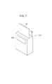
手術室12や病院内の必要な箇所には、図7に示すように、放射線検出カセッテ24が装填され、内蔵される電源部44(バッテリ92)の充電を行うクレードル518を配置すると好適である。この場合、クレードル518は、電源部44(バッテリ92)の充電だけでなく、クレードル518の無線通信機能又は有線通信機能を用いて、RIS29、HIS33、コンソール28等の外部機器との間で必要な情報の送受信を行うようにしてもよい。送受信する情報には、クレードル518に装填された放射線検出カセッテ24に記録された放射線画像情報を含めることができる。 As shown in FIG. 7, a
また、クレードル518に表示部520を配設し、この表示部520に対して、装填された当該放射線検出カセッテ24の充電状態や、放射線検出カセッテ24から取得した放射線画像情報を含む必要な情報を表示させるようにしてもよい。 In addition, a
さらに、複数のクレードル518をネットワークに接続し、各クレードル518に装填されている放射線検出カセッテ24の充電状態をネットワークを介して収集し、使用可能な充電状態にある放射線検出カセッテ24の所在を確認できるように構成することもできる。 Further, a plurality of
なお、本発明に係る放射線画像撮影システム及び放射線検出カセッテは、上述の実施の形態に限らず、本発明の要旨を逸脱することなく、種々の構成を採り得ることは勿論である。 Of course, the radiographic imaging system and the radiation detection cassette according to the present invention are not limited to the above-described embodiments, and various configurations can be adopted without departing from the gist of the present invention.
10、10a…放射線画像撮影システム 12…手術室
22…撮影装置 24、500…放射線検出カセッテ
25…給電装置 26…表示装置
28…コンソール 40…放射線検出器
44…電源部 46…カセッテ制御部
48、76、82、116…送受信機 49…エネルギ変換部
74…放射線源 80、90…電源
84、88…LC共振器 85…送信機
86…給電制御部 92…バッテリ
94…検出用LC共振器 95、110…受信機
96…エネルギ検出部 97…受電可否検出部
102…運転管理部 106…データ管理部
114…表示部 120…画像処理部
126…カセッテ情報管理部 128…給電情報管理部DESCRIPTION OF
Claims (6)
Translated fromJapanese前記放射線検出カセッテに無線による給電を行う給電装置と、
前記放射線検出カセッテ及び前記給電装置を制御する制御装置と、
を備える放射線画像撮影システムであって、
前記給電装置には、電気エネルギを変換して前記放射線検出カセッテに無線で供給する送電手段が設けられ、
前記放射線検出カセッテには、前記送電手段から供給された供給エネルギを電気エネルギに再変換するエネルギ変換部と、該放射線検出カセッテが前記送電手段から供給される前記供給エネルギを受電可能な領域にあるか否かを検出する受電可否検出部とが設けられ、
前記給電装置は、前記エネルギ変換部及び前記受電可否検出部で前記無線の有無を検出できる程度の弱い無線による給電を行う低出力運転、又は、前記弱い無線から強い無線に変更した高出力運転を行うことが可能であり、
前記給電装置が前記低出力運転を行っているときに、前記低出力運転による弱い無線を前記受電可否検出部が検出し、前記受電可否検出部が前記受電可能な領域内であるとの結果を検出した場合に、前記放射線検出カセッテは、当該結果に応じた無線給電可能信号を前記制御装置に送信し、
前記制御装置は、前記無線給電可能信号を受信し、当該無線給電可能信号に応じた給電開始信号を前記給電装置に送信し、
前記給電装置は、前記給電開始信号の受信に基づいて、前記低出力運転から前記高出力運転に変更することにより、前記送信手段から前記放射線検出カセッテへの前記供給エネルギの供給を開始させることを特徴とする放射線画像撮影システム。A radiation conversion panel that detects radiation that has passed through the subject and converts it into radiation image information; and a radiation detection cassette that is connected to the radiation conversion panel and has transmission means that transmits the radiation image information to image processing means;
A power supply device that wirelessly supplies power to the radiation detection cassette;
A control device for controlling the radiation detection cassette and the power supply device;
A radiographic imaging system comprising:
The power feeding device is provided with power transmission means for converting electric energy and supplying the radiation detection cassette wirelessly,
The radiation detection cassette has an energy conversion unit that reconverts supply energy supplied from the power transmission means into electrical energy, and the radiation detection cassette is in a region where the supply energy supplied from the power transmission means can be received. And a power reception availability detection unit for detecting whether or not
The power supply device performs low-power operation in which the energy conversion unit and the power reception availability detection unit can perform power supply by weak wireless power that can detect presence or absence of the wireless, or high-power operation in which the weak wireless power is changed to strong wireless power. Is possible and
When the power feeding device is performing the low output operation, the power reception availability detection unit detects weak radio due to the low output operation , and the result that the power reception availability detection unit is within the power reception possible region When detected, the radiation detection cassette transmits a wireless power feedable signal according to the result to the control device,
The control device receives the wireless power supply enable signal, transmits a power supply start signal corresponding to the wireless power supply enable signal to the power supply device,
The power supply device starts supply of the supply energy from the transmission unit to the radiation detection cassetteby changing from the low output operation to the high output operation based on reception of the power supply start signal. A featured radiographic imaging system.
前記放射線検出カセッテには、前記エネルギ変換部により再変換された前記電気エネルギを蓄電可能なバッテリが設けられていることを特徴とする放射線画像撮影システム。The system of claim 1, wherein
The radiation image capturing system according to claim 1, wherein the radiation detection cassette is provided with a battery capable of storing the electric energy reconverted by the energy conversion unit.
前記放射線検出カセッテには、前記受電可否検出部により前記受電可能な領域内であるとの結果が検出された場合に、前記エネルギ変換部による前記電気エネルギへの再変換の開始を指示する制御部が設けられていることを特徴とする放射線画像撮影システム。The system according to claim 1 or 2,
The control unit for instructing the radiation detection cassette to start reconversion to the electric energy by the energy conversion unit when the result indicating that the power reception is possible is detected by the power reception availability detection unit. A radiographic imaging system characterized in that is provided.
前記受電可否検出部により前記受電可能な領域外であるとの結果が検出された場合に、前記放射線検出カセッテの駆動電源として前記バッテリを選択する電源選択部を備えることを特徴とする放射線画像撮影システム。The system according to claim 2 or 3,
A radiographic imaging, comprising: a power source selection unit that selects the battery as a driving power source of the radiation detection cassette when a result that the power reception possibility detection unit detects that the power is out of the power receiving region is detected. system.
前記受電可否検出部による検出結果が前記受電可能な領域外であることを外部に通知する通知部を備えることを特徴とする放射線画像撮影システム。The system according to any one of claims 1 to 4,
A radiographic imaging system, comprising: a notification unit that notifies the outside that a detection result by the power reception availability detection unit is outside the region where power can be received.
外部の給電装置で電気エネルギから変換され無線で供給される供給エネルギを、電気エネルギに再変換するエネルギ変換部と、
当該放射線検出カセッテが前記無線で供給される前記供給エネルギを受電可能な領域にあるか否かを検出する受電可否検出部と、
をさらに備え、
前記給電装置は、前記エネルギ変換部及び前記受電可否検出部で前記無線の有無を検出できる程度の弱い無線による給電を行う低出力運転、又は、前記弱い無線から強い無線に変更した高出力運転を行うことが可能であり、
前記給電装置が前記低出力運転を行っているときに、前記低出力運転による弱い無線を前記受電可否検出部が検出し、前記受電可否検出部が前記受電可能な領域内であるとの結果を検出した場合に、前記放射線検出カセッテは、当該結果に応じた無線給電可能信号を外部の制御装置に送信し、
前記制御装置は、前記無線給電可能信号を受信し、当該無線給電可能信号に応じた給電開始信号を前記給電装置に送信し、
前記給電装置は、前記給電開始信号の受信に基づいて、前記低出力運転から前記高出力運転に変更することにより、前記送信手段から前記放射線検出カセッテへの前記供給エネルギの供給を開始させることを特徴とする放射線検出カセッテ。A radiation detection cassette comprising: a radiation conversion panel that detects radiation transmitted through a subject and converts the radiation into radiation image information; and a transmission unit that is connected to the radiation conversion panel and transmits the radiation image information to an image processing unit. ,
An energy conversion unit that converts supply energy converted from electric energy by an external power supply device and supplied wirelessly into electric energy; and
A power reception availability detection unit that detects whether or not the radiation detection cassette is in a region where the supply energy supplied wirelessly can be received;
Further comprising
The power supply device performs low-power operation in which the energy conversion unit and the power reception availability detection unit can perform power supply by weak wireless power that can detect presence or absence of the wireless, or high-power operation in which the weak wireless power is changed to strong wireless power. Is possible and
When the power feeding device is performing the low output operation, the power reception availability detection unit detects weak radio due to the low output operation , and the result that the power reception availability detection unit is within the power reception possible region When detected, the radiation detection cassette transmits a wireless power feedable signal according to the result to an external control device,
The control device receives the wireless power supply enable signal, transmits a power supply start signal corresponding to the wireless power supply enable signal to the power supply device,
The power supply device starts supply of the supply energy from the transmission unit to the radiation detection cassetteby changing from the low output operation to the high output operation based on reception of the power supply start signal. Characteristic radiation detection cassette.
Priority Applications (1)
| Application Number | Priority Date | Filing Date | Title |
|---|---|---|---|
| JP2008170226AJP5497274B2 (en) | 2007-07-30 | 2008-06-30 | Radiation imaging system and radiation detection cassette |
Applications Claiming Priority (3)
| Application Number | Priority Date | Filing Date | Title |
|---|---|---|---|
| JP2007197243 | 2007-07-30 | ||
| JP2007197243 | 2007-07-30 | ||
| JP2008170226AJP5497274B2 (en) | 2007-07-30 | 2008-06-30 | Radiation imaging system and radiation detection cassette |
Publications (2)
| Publication Number | Publication Date |
|---|---|
| JP2009050690A JP2009050690A (en) | 2009-03-12 |
| JP5497274B2true JP5497274B2 (en) | 2014-05-21 |
Family
ID=40502291
Family Applications (1)
| Application Number | Title | Priority Date | Filing Date |
|---|---|---|---|
| JP2008170226AActiveJP5497274B2 (en) | 2007-07-30 | 2008-06-30 | Radiation imaging system and radiation detection cassette |
Country Status (1)
| Country | Link |
|---|---|
| JP (1) | JP5497274B2 (en) |
Families Citing this family (2)
| Publication number | Priority date | Publication date | Assignee | Title |
|---|---|---|---|---|
| US8929510B2 (en) | 2010-06-30 | 2015-01-06 | Fujifilm Corporation | Radiographic image capturing apparatus and radiographic image capturing system |
| JP5628098B2 (en)* | 2010-06-30 | 2014-11-19 | 富士フイルム株式会社 | Radiation imaging system and power supply method for radiation imaging apparatus |
Family Cites Families (6)
| Publication number | Priority date | Publication date | Assignee | Title |
|---|---|---|---|---|
| JP2004166459A (en)* | 2002-11-15 | 2004-06-10 | Mitsui Eng & Shipbuild Co Ltd | Wireless power supply |
| JP2004180931A (en)* | 2002-12-03 | 2004-07-02 | Canon Inc | X-ray imaging device |
| JP2006141170A (en)* | 2004-11-15 | 2006-06-01 | Sharp Corp | Power supply system, power transmission device and power reception device used therefor |
| JP2006263322A (en)* | 2005-03-25 | 2006-10-05 | Konica Minolta Medical & Graphic Inc | Radiographic imaging system, console, and program executed in console |
| JP2006353042A (en)* | 2005-06-17 | 2006-12-28 | Ntt Docomo Inc | Power transmission device, power reception device, authentication / billing proxy device, charging system, power transmission method, power reception method, charging method |
| JP4738177B2 (en)* | 2006-01-11 | 2011-08-03 | 三菱重工業株式会社 | Transportation system charging method and charging system |
- 2008
- 2008-06-30JPJP2008170226Apatent/JP5497274B2/enactiveActive
Also Published As
| Publication number | Publication date |
|---|---|
| JP2009050690A (en) | 2009-03-12 |
Similar Documents
| Publication | Publication Date | Title |
|---|---|---|
| KR101468487B1 (en) | Radiation detecting cassette and radiation image picking-up system | |
| JP5274915B2 (en) | Radiation detection cassette and radiographic imaging system | |
| JP2009028449A (en) | Radiation imaging system and radiation generator | |
| US7829859B2 (en) | Radiation detecting cassette and radiation image capturing system | |
| JP2009080103A (en) | Cassette system | |
| JP5485571B2 (en) | Radiation detection apparatus, radiographic imaging system, and radiographic imaging method | |
| JP2011252913A (en) | Medical system | |
| JP2009034484A (en) | Radiation imaging system | |
| JP2010032980A (en) | Cassette | |
| JP2013233440A (en) | Radiographic system | |
| JP2009053662A (en) | Cassette | |
| JP5192914B2 (en) | Cassette and radiographic imaging system | |
| JP5887390B2 (en) | Radiation imaging system | |
| JP2009048171A (en) | Cassette device and cassette storage bag provided in the cassette device | |
| JP5274916B2 (en) | Radiation imaging system | |
| JP2009181001A (en) | Radiation converter | |
| JP5497274B2 (en) | Radiation imaging system and radiation detection cassette | |
| JP4862016B2 (en) | Radiation detection cassette and radiographic imaging system | |
| JP2009061263A (en) | Radiographic imaging system and method of setting minimum transmission radio wave intensity in the system | |
| JP5422202B2 (en) | Radiation imaging system and method for charging radiation detection cassette | |
| JP5156495B2 (en) | Mobile X-ray equipment | |
| JP5294725B2 (en) | Radiation imaging system | |
| JP5011217B2 (en) | Cassette and mobile X-ray imaging apparatus | |
| JP2009061256A (en) | Radiographic imaging system and method of setting transmission radio wave intensity in the system | |
| US20090028401A1 (en) | Radiation image capturing system |
Legal Events
| Date | Code | Title | Description |
|---|---|---|---|
| A621 | Written request for application examination | Free format text:JAPANESE INTERMEDIATE CODE: A621 Effective date:20110127 | |
| A131 | Notification of reasons for refusal | Free format text:JAPANESE INTERMEDIATE CODE: A131 Effective date:20120904 | |
| A977 | Report on retrieval | Free format text:JAPANESE INTERMEDIATE CODE: A971007 Effective date:20120906 | |
| A521 | Request for written amendment filed | Free format text:JAPANESE INTERMEDIATE CODE: A523 Effective date:20121023 | |
| A131 | Notification of reasons for refusal | Free format text:JAPANESE INTERMEDIATE CODE: A131 Effective date:20130423 | |
| A521 | Request for written amendment filed | Free format text:JAPANESE INTERMEDIATE CODE: A523 Effective date:20130617 | |
| TRDD | Decision of grant or rejection written | ||
| A01 | Written decision to grant a patent or to grant a registration (utility model) | Free format text:JAPANESE INTERMEDIATE CODE: A01 Effective date:20140225 | |
| A61 | First payment of annual fees (during grant procedure) | Free format text:JAPANESE INTERMEDIATE CODE: A61 Effective date:20140306 | |
| R150 | Certificate of patent or registration of utility model | Ref document number:5497274 Country of ref document:JP Free format text:JAPANESE INTERMEDIATE CODE: R150 | |
| R250 | Receipt of annual fees | Free format text:JAPANESE INTERMEDIATE CODE: R250 | |
| R250 | Receipt of annual fees | Free format text:JAPANESE INTERMEDIATE CODE: R250 | |
| R250 | Receipt of annual fees | Free format text:JAPANESE INTERMEDIATE CODE: R250 | |
| R250 | Receipt of annual fees | Free format text:JAPANESE INTERMEDIATE CODE: R250 | |
| R250 | Receipt of annual fees | Free format text:JAPANESE INTERMEDIATE CODE: R250 | |
| R250 | Receipt of annual fees | Free format text:JAPANESE INTERMEDIATE CODE: R250 | |
| R250 | Receipt of annual fees | Free format text:JAPANESE INTERMEDIATE CODE: R250 | |
| R250 | Receipt of annual fees | Free format text:JAPANESE INTERMEDIATE CODE: R250 |