JP5495283B2 - Cartridge removal method - Google Patents
Cartridge removal methodDownload PDFInfo
- Publication number
- JP5495283B2 JP5495283B2JP2008252795AJP2008252795AJP5495283B2JP 5495283 B2JP5495283 B2JP 5495283B2JP 2008252795 AJP2008252795 AJP 2008252795AJP 2008252795 AJP2008252795 AJP 2008252795AJP 5495283 B2JP5495283 B2JP 5495283B2
- Authority
- JP
- Japan
- Prior art keywords
- cartridge
- cell
- latch lever
- predetermined position
- picker
- Prior art date
- Legal status (The legal status is an assumption and is not a legal conclusion. Google has not performed a legal analysis and makes no representation as to the accuracy of the status listed.)
- Active
Links
- 238000000034methodMethods0.000titleclaimsdescription19
- 230000007246mechanismEffects0.000claimsdescription83
- 238000003825pressingMethods0.000claimsdescription16
- 238000000605extractionMethods0.000claimsdescription6
- 238000003780insertionMethods0.000claimsdescription5
- 230000037431insertionEffects0.000claimsdescription5
- 238000007599dischargingMethods0.000claimsdescription4
- 210000004027cellAnatomy0.000description82
- 238000012546transferMethods0.000description3
- 210000002421cell wallAnatomy0.000description2
- 230000032683agingEffects0.000description1
- 238000013459approachMethods0.000description1
- 230000007248cellular mechanismEffects0.000description1
- 238000004891communicationMethods0.000description1
- 238000013500data storageMethods0.000description1
- 230000006866deteriorationEffects0.000description1
- 230000003287optical effectEffects0.000description1
Images


Classifications
- G—PHYSICS
- G11—INFORMATION STORAGE
- G11B—INFORMATION STORAGE BASED ON RELATIVE MOVEMENT BETWEEN RECORD CARRIER AND TRANSDUCER
- G11B15/00—Driving, starting or stopping record carriers of filamentary or web form; Driving both such record carriers and heads; Guiding such record carriers or containers therefor; Control thereof; Control of operating function
- G11B15/675—Guiding containers, e.g. loading, ejecting cassettes
- G11B15/68—Automatic cassette changing arrangements; automatic tape changing arrangements
- G11B15/682—Automatic cassette changing arrangements; automatic tape changing arrangements with fixed magazines having fixed cassette storage cells, e.g. in racks
- G11B15/6835—Automatic cassette changing arrangements; automatic tape changing arrangements with fixed magazines having fixed cassette storage cells, e.g. in racks the cassettes being transferred to a fixed recorder or player using a moving carriage
- G—PHYSICS
- G11—INFORMATION STORAGE
- G11B—INFORMATION STORAGE BASED ON RELATIVE MOVEMENT BETWEEN RECORD CARRIER AND TRANSDUCER
- G11B15/00—Driving, starting or stopping record carriers of filamentary or web form; Driving both such record carriers and heads; Guiding such record carriers or containers therefor; Control thereof; Control of operating function
- G11B15/675—Guiding containers, e.g. loading, ejecting cassettes
- G11B15/68—Automatic cassette changing arrangements; automatic tape changing arrangements
- G11B15/6885—Automatic cassette changing arrangements; automatic tape changing arrangements the cassettes being conveyed within a cassette storage location, e.g. within a storage bin or conveying by belt
- G—PHYSICS
- G11—INFORMATION STORAGE
- G11B—INFORMATION STORAGE BASED ON RELATIVE MOVEMENT BETWEEN RECORD CARRIER AND TRANSDUCER
- G11B17/00—Guiding record carriers not specifically of filamentary or web form, or of supports therefor
- G11B17/22—Guiding record carriers not specifically of filamentary or web form, or of supports therefor from random access magazine of disc records
- G11B17/225—Guiding record carriers not specifically of filamentary or web form, or of supports therefor from random access magazine of disc records wherein the disks are transferred from a fixed magazine to a fixed playing unit using a moving carriage
- Y—GENERAL TAGGING OF NEW TECHNOLOGICAL DEVELOPMENTS; GENERAL TAGGING OF CROSS-SECTIONAL TECHNOLOGIES SPANNING OVER SEVERAL SECTIONS OF THE IPC; TECHNICAL SUBJECTS COVERED BY FORMER USPC CROSS-REFERENCE ART COLLECTIONS [XRACs] AND DIGESTS
- Y10—TECHNICAL SUBJECTS COVERED BY FORMER USPC
- Y10T—TECHNICAL SUBJECTS COVERED BY FORMER US CLASSIFICATION
- Y10T29/00—Metal working
- Y10T29/49—Method of mechanical manufacture
- Y10T29/49815—Disassembling
- Y10T29/49822—Disassembling by applying force
Landscapes
- Automatic Disk Changers (AREA)
- Automatic Tape Cassette Changers (AREA)
Description
Translated fromJapanese本発明は、磁気テープ、磁気ディスク、光ディスク、あるいは光磁気ディスク等のカートリッジを複数格納するとともに、それらのカートリッジの中から所望のカートリッジを選択的に取り出し、内部のドライブ装置によってデータの読み取り/書き込みを行うライブラリ装置におけるカートリッジの取り出し方法に関するものである。 The present invention stores a plurality of cartridges such as a magnetic tape, a magnetic disk, an optical disk, or a magneto-optical disk, selectively takes out a desired cartridge from these cartridges, and reads / writes data by an internal drive device. The present invention relates to a method for taking out a cartridge in a library apparatus that performs the above.
特許文献1に示されているように、マガジンの複数のセル内にカートリッジを格納し、それらのカートリッジの中から所望のカートリッジを選択的に取り出して、ドライブ装置によってデータの読み取り/書き込みを行うライブラリ装置(データストレージシステム等と称される場合もある)が知られている。 As shown in Patent Document 1, a cartridge that stores cartridges in a plurality of cells of a magazine, selectively takes out a desired cartridge from these cartridges, and reads / writes data by a drive device An apparatus (sometimes called a data storage system or the like) is known.
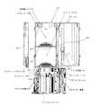
図10Aは、本発明に関連するライブラリ装置の平面図である。図10Bは、本発明に関連するライブラリ装置の正面図である。図11は本発明に関連するライブラリ装置の一例の外観斜視図である。 FIG. 10A is a plan view of a library apparatus related to the present invention. FIG. 10B is a front view of the library apparatus related to the present invention. FIG. 11 is an external perspective view of an example of a library apparatus related to the present invention.
図10A及び図11に示すように、本発明に関連するライブラリ装置は、マガジン1200と、2つのドライブ装置1600と、アクセッサ機構1400とを有する。マガジン1200は、カートリッジ1100を水平姿勢で積み重ねられた状態に収容する複数のセル1300を有する。ドライブ装置1600は、カートリッジ1100内の記録媒体に対してデータの読み取り/書き込みを行う。アクセッサ機構1400は、カートリッジ1100の移送を行う。 As shown in FIGS. 10A and 11, the library apparatus related to the present invention includes a magazine 1200, two
このライブラリ装置に用いられるセル1300は、1つのセル内に複数のカートリッジ1100を一列に収納することができる。
しかしながら、複数のカートリッジを収納可能なセルの場合、セルやカートリッジの組立誤差あるいは経年劣化が原因で、セルの奥に収納したカートリッジがセルの壁面に引っかかってしまい、セルからカートリッジを取り出せない場合があった。 However, in the case of a cell that can store a plurality of cartridges, the cartridge stored in the back of the cell may be caught by the cell wall due to assembly errors or aging deterioration of the cell or cartridge, and the cartridge cannot be removed from the cell. there were.
このような非常時に備えてカートリッジを突き出すなどしてカートリッジをセル外に排出する機構をライブラリ装置に設けることが考えられる。しかしながら、通常の動作では、セルの奥に収納したカートリッジがセルの壁面に引っかかってしまうことはないため、このような非常時のためにのみ別途排出機構を設けるのは無駄が多く、また、部品点数の増加によるコストアップも問題となる。 In order to prepare for such an emergency, it is conceivable to provide the library apparatus with a mechanism for ejecting the cartridge out of the cell by protruding the cartridge. However, in normal operation, the cartridge housed in the back of the cell is not caught on the cell wall, so it is wasteful to provide a separate discharge mechanism only for such an emergency. Cost increase due to the increase in the number of points is also a problem.
そこで、本発明は、部品点数の増加を来すことなく、セルの奥に収納したカートリッジがセルの壁面に引っかかってしまったカートリッジを取り出すことができるカートリッジの取り出し方法を提供することを目的とする。 SUMMARY OF THE INVENTION Accordingly, an object of the present invention is to provide a cartridge take-out method capable of taking out a cartridge in which a cartridge housed in the back of the cell is caught on the wall surface of the cell without increasing the number of parts. .
上記目的を達成するため、本発明のカートリッジの取り出し方法は、
複数のカートリッジを、カートリッジの挿抜方向に平行な壁面に沿って一列に収納するセルと、
セルからカートリッジが引き抜かれる第1の方向に移動することでセル内の所定の位置にあるカートリッジをセル外へと移動させるピッカー機構と、
所定の位置よりも第1の方向とは反対の第2の方向側でセルに収納されたカートリッジを所定の位置へ向けて付勢する第1の付勢手段と、
カートリッジに係合することでカートリッジをセル内の所定の位置に保持する係合位置と、カートリッジとの係合が解除される、該係合位置よりも第1の方向と交わる第3の方向側の解除位置と、の間で揺動可能に壁面に設けられたラッチレバーと、
ラッチレバーを第3の方向とは反対の第4の方向に付勢する第2の付勢手段と、を有するライブラリ装置のカートリッジ取り出し方法において、
ピッカー機構に設けられた排出時解除部を、ラッチレバーの面のうち第4の方向を向く被当接面に当接させた後、ラッチレバーが第3の方向に移動するようにピッカー機構を移動させることでラッチレバーを第3の方向に押圧して第2の付勢手段の付勢力を高める押圧工程と、
押圧工程後、ピッカー機構を第1の方向に移動させることで排出時解除部を被当接面から離して第2の付勢手段の付勢力を解放する解放工程と、を含み、
排出時解除部の第2の方向側の端部が、ラッチレバーが係合位置にある状態での被当接面の第1の方向側の端部の位置よりも第3の方向側を解放工程中に通るように、ピッカー機構を移動させることを特徴とする。In order to achieve the above object, a method for taking out the cartridge of the present invention comprises:
A cell for storing a plurality of cartridges in a row along a wall surface parallel to the insertion / extraction direction of the cartridge;
A picker mechanism for movinga cartridge at apredetermined position in the cell to the outside of the cell by moving in afirst direction inwhich the cartridge is pulled out of the cell;
A first urging means for urging the cartridge stored in the cell toward the predetermined position on the second direction side opposite to the first direction from the predetermined position;
Engaging position to hold the cartridge inposition in the cell by engaging the cartridge, the engagement between the cartridgeRu isreleased, a third direction intersecting the first direction than the engagement position and releaseposition, a latch lever providedto swingablywall between,
In a cartridge ejection method for a library apparatus, comprising: asecond urging unit that urges the latch lever in afourth directionopposite tothe third direction .
Afterthe discharge time release part provided in the pickermechanism, is brought into contact withthe contact surface facing the fourth direction in the plane of the latch lever,pin on so that the latch leverto move ina third direction Kka A pressing step for increasing the biasing force ofthe second biasing meansby pressingthe latch lever inthe third direction by moving the mechanism;
After the pressing step,seen including a releasing step, the releasing the biasing forceof thesecond biasing meansrelease the picker mechanismemissions during release part from the contact surface by moving ina firstdirection,
The end portion on the second direction side of the release portion at the time of ejection releases the third direction side from the position of the end portion on the first direction side of the contacted surface when the latch lever is in the engagement position. The picker mechanism is moved so as to pass through the process .
本発明によれば、部品点数の増加を来すことなく、セルの奥に収納したカートリッジがセルの壁面に引っかかってしまったカートリッジを取り出すことができる。 According to the present invention, it is possible to take out a cartridge in which a cartridge housed in the back of the cell is caught on the wall surface of the cell without increasing the number of parts.
次に、図面を参照しながら本発明の実施の形態について説明する。 Next, embodiments of the present invention will be described with reference to the drawings.
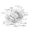
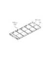
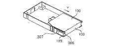
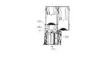
図1Aは本実施形態のライブラリ装置の平面図であり、図1Bは本実施形態のライブラリ装置の正面図である。図2は本実施形態のライブラリ装置の外観斜視図である。図3は、アクセッサ機構の平面図及びセルの平面図及び側面図であり、図4はアクセッサ機構の構成を示す斜視図である。図5はマガジンの外観斜視図であり、図6A〜図6Cは、セルの機構を説明するための斜視図である。また、図7は、本実施形態のライブラリ装置に用いられるセル及びのカートリッジの模式的な平面図である。 FIG. 1A is a plan view of the library apparatus of the present embodiment, and FIG. 1B is a front view of the library apparatus of the present embodiment. FIG. 2 is an external perspective view of the library apparatus of this embodiment. FIG. 3 is a plan view of the accessor mechanism, a plan view and a side view of the cell, and FIG. 4 is a perspective view showing a configuration of the accessor mechanism. FIG. 5 is an external perspective view of the magazine, and FIGS. 6A to 6C are perspective views for explaining a cell mechanism. FIG. 7 is a schematic plan view of cells and cartridges used in the library apparatus of this embodiment.
本実施形態のライブラリ装置は、マガジン200と、ドライブ装置600と、アクセッサ機構400とを有する。マガジン200は、カートリッジ100を収納する複数のセル300を有する。ドライブ装置600は、カートリッジ100内の記録媒体に対してデータの読み取り/書き込みを行う。アクセッサ機構400は、カートリッジ100の移送を行う。 The library apparatus of this embodiment includes a
本実施形態では、1つのマガジン200とドライブ装置600とが隣接して配置されており、マガジン200内に収納されたセル300の開口部305とドライブ装置600の開口部605との開口方向は同じ方向を向いている。
(アクセッサ機構)
アクセッサ機構400は、駆動部401により往復移動可能な構成となっており、また、ピッカーフレーム510を搭載している。このピッカーフレーム510内にはピッカー機構500がY方向に移動可能に搭載されている。In this embodiment, one
(Accessor mechanism)
The
駆動部401は、モータおよび駆動ギア列からなる。この駆動ギア列のファイナルギヤはX方向に延びたラック700と係合している。駆動部401のモータを正逆方向に回転駆動させると、アクセッサ機構400は、その駆動力によって、ガイドレール457に沿って図示X方向に往復移動する。なお、X方向へのアクセッサ機構400の移動機構は、正確な位置決めが可能であれば、周知のタイミングベルトとプーリの組み合わせにより構成されているものであってもよい。 The
また、本実施形態では、アクセッサ機構400は水平方向にのみ移動するものとして説明しているが、マガジン200が積層されて多段化された場合には垂直方向に移動可能な機構を備えることとなる。
(ピッカー機構)
ピッカー機構500は、カートリッジ100を保持してこれをマガジン200のセル300やドライブ装置600に対して出し入れする動作を行う。ピッカー機構500を搭載したアクセッサ機構400は、そのような動作によって、カートリッジ100を、セル300とドライブ装置600との間、各セル300の間、あるいは各ドライブ装置600の間で移送することが可能である。In this embodiment, the
(Picker mechanism)
The
ピッカー機構500は、前面543、第1の側面541、第1の側面541と反対側に位置する第2の側面542、及び後面からなる箱状の本体501を有する。 The
アクセッサ機構400の水平移動方向に対して交差する方向の側面である第1の側面541には、ピッカーアーム521が設けられている。ピッカーアーム521は第1の側面541から前面543の方向に延び、前面543を超えたところで第2の側面542に向かって先端部分が曲げられた形状を有する。 A
第2の側面542は、後述するように、セル300のラッチレバー306を押し開くための排出時解除部522として機能する。なお、本実施形態では第2の側面542を排出時解除部522として用いているが、排出時解除部522を第2の側面542側に別途設けてもよい。 As will be described later, the
ピッカー機構500は本体501内にピッカー駆動モータ530を収納している。ピッカー駆動モータ530はピッカー機構500をピッカーフレーム510内にてY方向に駆動させる。 The
前面543には、本体501内から延出したセンサシャフト550が設けられている。センサシャフト550は、セル300内のカートリッジ100がピッカー機構500により取り出すことができる所定の位置に位置しているか否かを検出するためのセンサである。センサシャフト550は、ピッカー機構500がカートリッジ100を取り出す位置まで移動した際に、カートリッジ100に当接して本体501内に押し込まれることでカートリッジ100が所定の位置に位置していることを検出する。一方、ピッカー機構500がカートリッジ100を取り出すための位置まで移動したにもかかわらず、センサシャフト550が押し込まれない場合、カートリッジ100が所定の位置に位置していないことを検出する。
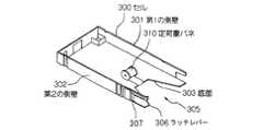
(セル)
セル300は、長手方向に2つのカートリッジ100を収納可能ないわゆるディープセルであり、図6Aに示すように、その底面303に、カートリッジ100を開口部305側に付勢するための定荷重バネ310を有する。A
(cell)
The
また、セル300は、第1の側壁301の反対側に位置する第2の側壁302の開口部305側にラッチレバー306及びラッチレバースプリング307を有する。第1の側壁301及び第2の側壁302はカートリッジ100の挿抜方向に対して平行に設けられている。ラッチレバー306は、カートリッジ100に係合することでカートリッジ100をセル300内に保持する係合位置B(図9B参照)と、カートリッジ100との係合が解除された解除位置A(図9A参照)との間で揺動可能に設けられている。また、ラッチレバー306と第2の側壁302とは一体的に設けられているが、別体として設けられていてもよい。ラッチレバー306は、その一部を切り欠いて形成された先端部分に開口部305側に曲げられた係合部を有する。ラッチレバー306は、カートリッジ100の後面103の第2の側面105側に係合することでカートリッジ100がセル300から意図せずに抜け出ることを防止する。 The
ラッチレバースプリング307は、ラッチレバー306を解除位置Aから係合位置Bに向かう方向に付勢する第2の付勢手段である。なお、本実施形態では、ラッチレバー306とラッチレバースプリング307とを別体とした構成を例示しているが本発明はこれに限定されるものではない。ラッチレバー306が十分な弾性を有するのであれば、ラッチレバー306自体の弾性を付勢手段として用いてもよい。The
定荷重バネ310は、一定の曲率で密着巻きされた薄板で、その外端部を直線に引き延ばして使用するバネであり、荷重がストロークによらず、ほぼ一定となる特性を有する。図6Bのように1個のカートリッジ100がセル300内に収納されている場合と、図6Cのように2個のカートリッジ100が収納されている場合のいずれにおいても、ほぼ同じ荷重をカートリッジ100に付与する。なお、カートリッジ100を開口部305側に付勢するための第1の付勢手段としては定荷重バネ310に限定されるものではなく、通常のコイルバネ等であってもよい。なお、コイルバネの場合、そのストロークが長くなるほど、荷重が大きくなる。
(カートリッジ)
カートリッジ100は、例えばLAN(Local Area Network)やインターネット等の通信回線を介してライブラリ装置に接続されたコンピュータ(不図示)が共有するデータを読み書きする記録媒体である。そのような記録媒体としては、例えば、LTOやDLT等のテープメディア、それぞれハウジング内に収容されているDVD、光磁気ディスク(MO)、あるいはMD等のディスクメディア等がある。The
(cartridge)
The
本実施形態のカートリッジ100は、図7に示すように、第1の側面104であって、後面103付近には係合穴102が形成されている。また、第2の側面105と前面106との間の角部分にはテーパ面101が形成されている。なお、第2の側面105は、第1の側面104とは反対側に形成されている面である。係合穴102はピッカーアーム521が係合するための穴である。テーパ面101は、カートリッジ100がセル300内に挿入される際に、ラッチレバー306を押し広げるために設けられた傾斜面である。また、第1の側面104及び第2の側面105は、セル300への挿入方向に対して平行となる面を構成している。また、テーパ面101は、対象となる面の一部がテーパ面になっている。 As shown in FIG. 7, the
なお、本実施形態では、テーパ面101は、第2の側面105と前面106との間の角部分に形成されているが、ラッチレバー306の位置によっては、第2の側面105以外の、セル300への挿入方向に対して平行な面と前面106との間の角部分に形成されていてもよい。
(ドライブ装置)
ドライブ装置600は、ドライブ装置600に装填されたカートリッジ100に書き込まれたデータを読み取り、また、コンピュータのオペレータが更新したデータをカートリッジ100に書きこむリード/ライト装置である。In the present embodiment, the
(Drive device)
The drive device 600 is a read / write device that reads data written to the
次に、本ライブラリ装置におけるカートリッジ100の取り出し動作について、図8A〜図8Gを参照して説明する。なお、以下の説明における取り出し動作は、一旦カートリッジ100を取り出そうとしてにもかかわらず、カートリッジ100が所定の位置に位置していなかったため、取り出しが行えず再度取り出し動作を行う例について説明する。以下、再度の取り出し動作をリトライ動作と称することもある。
(1)セルからのカートリッジの取り出し動作
図8A〜図8Gは、マガジン200のセル300内に収納されたカートリッジ100を取り出す動作を示す図である。また、図9Aは図8Cの要部拡大図であり、図9Bは図8Dの要部拡大図である。Next, an operation of taking out the
(1) Operation for Removing Cartridge from Cell FIGS. 8A to 8G are views showing an operation for taking out the
なお、図中、Y1方向は、Y方向のうち、ピッカー機構500がセル300に近づいていく第2の方向であり、Y2方向は、ピッカー機構500がセル300から遠ざかっていく第1の方向を指す。また、X1方向は、アクセッサ機構400が、カートリッジ100の第1の側面104側からラッチレバー306が設けられた第2の側面105側へと移動する第3の方向であり、X2方向は、アクセッサ機構400はその逆の第4の方向を指す。In the figure,Y 1 direction, among the Y-direction, asecond
図8A〜図8Gでは、2つの並列されたセル300a、300b内にそれぞれカートリッジ100a、100bが1つずつ収納されている。図8Aに示す状態で、セル300b内のカートリッジ100bは、ピッカー機構500により取り出し可能な所定に位置に位置している。一方、セル300a内のカートリッジ100aは、セル300aの奥まった位置で第2の側壁302に引っかかることでピッカー機構500により取り出し可能な所定に位置に位置していない状態を示している。なお、ここでは、カートリッジ100aの引っかかりは、カートリッジ100aと第2の側壁302との間の摩擦力によるものであるものとして説明する。しかし、カートリッジ100aとセル300aを構成する壁面のいずれかとの間の摩擦力により引っかかっている状態であっても、以下に説明するリトライ動作が同様に行われる。 8A to 8G,
以下、セル300a内のカートリッジ100aを取り出すリトライ動作について説明する。 Hereinafter, a retry operation for taking out the
図8Aに示すようにセル300aからカートリッジ100aを取り出す際には、まず、アクセッサ機構400を移動させてピッカーフレーム510の開口部をセル300aから取り出すカートリッジ100aに対向する位置に配置させる。
このとき、ピッカー機構500のピッカーアーム521はピッカーフレーム510内に収容されている。また、図8Aに示す状態では、ピッカー機構500は、ピッカーフレーム510内にて、ピッカー機構500がY1方向に移動したとしても、ラッチレバー306の端部306aと、ピッカー機構500の第2の側面542とが衝突しない位置に配置されている。また、この位置はピッカー機構500がY1方向に移動したとしても、ピッカーアーム521がカートリッジ100に衝突しない位置でもある。When removing the
At this time, the
次に、図8Bに示すように、ピッカー機構500をセル300の方向(Y1方向)に向けて移動させる。本来であれば、ピッカー機構500の本体501の前面543とカートリッジ100aの後面103とが当接する位置にてピッカー機構500が停止する。しかしながら、カートリッジ100aを取り出す位置に移動してもカートリッジ100aの後面103がセル300の開口部305まで達していない。このため、ピッカー機構500のセンサシャフト550とカートリッジ100aの後面103との間には距離aが存在することとなる。すなわち、センサシャフト550は、カートリッジ100aが取り出し可能な所定の位置に位置していないことを検出する。Next, as shown in FIG. 8B, it moves in the direction of the
そこで、リトライ動作が行われることとなる。 Therefore, a retry operation is performed.
図8C、あるいは図9Aに示すように、アクセッサ機構400をラッチレバー306の方向(X1方向)に向けて移動させる。アクセッサ機構400のこのX1方向への移動により、ピッカー機構500の第2の側面542がラッチレバー306を開く方向に押し広げて退避させる。すなわち、ラッチレバー306の端部306aは係合位置Bから、カートリッジ100aとの係合が解除された解除位置Aまで移動する。これに伴い、解除位置Aから係合位置Bに向けてラッチレバー306を付勢するラッチレバースプリング307の付勢力は高められることとなる。この図8Cに示す工程を押圧工程とする。As shown in FIG. 8C or FIG. 9A,, it moves towards the
次に、図8D、あるいは図9Bに示すように、この状態からピッカー機構500をY2方向へと後退させる。つまり、ラッチレバー306の端部306aに対するピッカー機構500の第2の側面542の押し付けを突然解除する。この突然の解除により、押し縮められて高まっていたラッチレバースプリング307の付勢力が瞬時に解放されることとなる。なお、この図8Dに示す工程を解放工程とする。付勢力が瞬時に解放されることで、ラッチレバー306は解除位置Aと係合位置Bとの間にて激しく揺動する。そしてこの揺動がセル300aの第2の側壁302に伝達される。第2の側壁302に伝達された振動は、カートリッジ100aが摩擦によって引っかかっている第2の側壁302の引っかかり部分にも到達する。振動によりカートリッジ100aが揺さぶられ、摩擦による引っかかりが解除される。摩擦による引っかかりが解除されることでカートリッジ100aは定荷重バネ310に付勢されてセル300の開口部305まで移動することとなる。Next, as shown in FIG. 8D or FIG. 9B, the
なお、押圧工程と解放工程とを一度行っただけでカートリッジ100aを取り出し可能な所定に位置にまで移動させることができない場合がある。このような場合は、押圧工程と解放工程とを交互に繰り返し実行てもよい。 In some cases, the
また、押圧工程と解放工程とを交互に繰り返す場合、押圧工程における、アクセッサ機構400のこのX1方向への移動量、すなわち、ピッカー機構500によるラッチレバー306の押し開き量は繰り返しの回数に比例して多くするようにしてもよい。つまり、始めのうちは、ラッチレバー306の押し開き量を少なくし、ラッチレバースプリング307の付勢力の高め具合を小さいものにしておき、小さな振動をセル300に与える。そして、段階的にセル300に与える振動を大きなものにしていく。このような制御を行うことで、小さな付勢力によって生じた振動でカートリッジ100aを所定の位置に移動させることができれば、ラッチレバー306やセル300に与える衝撃力が小さなもので済むので、製品の耐久性の点で好ましい。Also, when repeating the pressing step and the release step are alternately, in the pressing step, the amount of movement the X1
次に、図8Eに示すようにピッカー機構500をY1方向に移動させる。ピッカー機構500のセンサシャフト550は、カートリッジ100aの後面103に押し付けられることで本体501内に引っ込むことでカートリッジ100aが取り出し可能な所定の位置に位置していることを検出する。この際、ピッカー機構500は、ピッカーフレーム510内にて、ピッカー機構500がY1方向に移動したとしても、ラッチレバー306の端部306aと、ピッカー機構500の側面542とが衝突しない位置に配置されている。また、この位置はピッカー機構500がY1方向に移動したとしても、ピッカーアーム521がカートリッジ100に衝突しない位置でもある。Next, move the
次に、図8Fに示すように、アクセッサ機構400をラッチレバー306の方向(X1方向)に向けて移動させる。アクセッサ機構400のこのX1方向への移動により、ピッカー機構500の第2の側面542がラッチレバー306を開く方向に押し広げて退避させる。これにより、ラッチレバー306による係合が解除され、これと同時にピッカーアーム521の先端部がカートリッジ100aの係合穴102に嵌り込み係合する。つまり、本実施形態のライブラリ装置では、ピッカーアーム521が係合する方向とラッチレバー306が解除する方向とが同じX1方向であり、かつアクセッサ機構400の移動方向のうちのひとつであるX1方向としている。このため、本実施形態のライブラリ装置は、アクセッサ機構400をX1方向に移動させるという一つの挙動でピッカーアーム521の係合とラッチレバー306の解除を同時に行われる。Next, as shown in FIG. 8F, it is moved toward the
次に、図8Gに示すように、ラッチレバー306による係合が解除された状態でピッカー機構500をY2方向に移動することでピッカーアーム521がカートリッジ100aをセル300a内から引き抜く。Next, as shown in FIG. 8G, the
本実施形態の場合、カートリッジ100aは、定荷重バネ310によって開口部305の方向(Y2方向)へ付勢されている。このため、セル300内からのカートリッジ100aの引き抜きに要する駆動力は小さくて済む。In this embodiment, the
カートリッジ100aがセル300a内からピッカーフレーム510内に収納されることでカートリッジ100の取り出し動作を終了する。なお、カートリッジ100aがセル300a内から完全に引き抜かれることでラッチレバー306は退避していた位置からもとの位置に戻る。 When the
以上説明したように、本実施形態によれば、リトライ動作を行うことにより、セル300内に摩擦等により引っ掛かることで取り出しができない位置にあるカートリッジを、取り出しのための装置や部品等を別途設けることなく、取り出し可能な位置に移動させることができる。 As described above, according to the present embodiment, by performing a retry operation, a cartridge or a part for removing a cartridge in a position where it cannot be taken out by being caught in the
100、100a、100b カートリッジ
101 テーパ面
102 係合穴
103 後面
104 第1の側面
105 第2の側面
106 前面
200 マガジン
300、300a、300b セル
301 第1の側面
302 第2の側面
303 底面
305 開口部
306 ラッチレバー
306a 端部
307 ラッチレバースプリング
310 定荷重バネ
400 アクセッサ機構
401 駆動部
457 ガイドレール
500 ピッカー機構
501 本体
510 ピッカーフレーム
521 ピッカーアーム
522 排出時解除部
530 ピッカー駆動モータ
541 第1の側面
542 第2の側面
543 前面
550 センサシャフト
A 解除位置
B 係合位置100, 100a,
Claims (4)
Translated fromJapanese前記セルから前記カートリッジが引き抜かれる第1の方向に移動することで前記セル内の所定の位置にある前記カートリッジを前記セル外へと移動させるピッカー機構と、
前記所定の位置よりも前記第1の方向とは反対の第2の方向側で前記セルに収納された前記カートリッジを前記所定の位置へ向けて付勢する第1の付勢手段と、
前記カートリッジに係合することで前記カートリッジを前記セル内の前記所定の位置に保持する係合位置と、前記カートリッジとの係合が解除される、該係合位置よりも前記第1の方向と交わる第3の方向側の解除位置と、の間で揺動可能に前記壁面に設けられたラッチレバーと、
前記ラッチレバーを前記第3の方向とは反対の第4の方向に付勢する第2の付勢手段と、を有するライブラリ装置のカートリッジ取り出し方法において、
前記ピッカー機構に設けられた排出時解除部を、前記ラッチレバーの面のうち前記第4の方向を向く被当接面に当接させた後、前記ラッチレバーが前記第3の方向に移動するように前記ピッカー機構を移動させることで前記ラッチレバーを前記第3の方向に押圧して前記第2の付勢手段の付勢力を高める押圧工程と、
前記押圧工程後、前記ピッカー機構を前記第1の方向に移動させることで前記排出時解除部を前記被当接面から離して前記第2の付勢手段の付勢力を解放する解放工程と、を含み、
前記排出時解除部の前記第2の方向側の端部が、前記ラッチレバーが前記係合位置にある状態での前記被当接面の前記第1の方向側の端部の位置よりも前記第3の方向側を前記解放工程中に通るように、前記ピッカー機構を移動させることを特徴とするカートリッジ取り出し方法。A plurality of cartridges, cells for storing the cartridges in a row along a wall surface parallel to the insertion / extraction direction of the cartridges;
A picker mechanism for moving the cartridge at apredetermined position in the cell to the outside of the cell by moving in afirst direction inwhich the cartridge is pulled out from the cell ;
First biasing means for biasing the cartridge stored in the cell toward the predetermined position on the second direction side opposite to the first direction from the predetermined position;
Engaging position for holding the cartridge inthe predetermined position inthe cell by engagingbefore Symbol cartridge engagement with the cartridgeRu isreleased, the first direction than the engagement position a latch lever providedto swingablythe wall between thethird and release positionof the directionof intersecting the,
In a cartridge ejecting method for a library apparatus, comprising: asecond urging unit that urges the latch lever in afourth directionopposite to the third direction .
Afterthe discharging release portion provided in the picker mechanismis brought into contact with acontacted surface facing the fourth direction among the surfaces of the latch lever, the latch lever moves inthe third direction. a pressing step of pressing the latch leverin the third direction by moving thefront Symbol pickermechanism so that increasing the urging force of thesecond biasing means,
After the pressing step, the releasing step ofreleasing the urging force ofthe second urging means by movingthe picker mechanism inthe first directionto separate the discharging release part from the abutted surface ;only including,
The end portion on the second direction side of the discharging release portion is more than the position of the end portion on the first direction side of the contacted surface when the latch lever is in the engagement position. A method for removing a cartridge, wherein the picker mechanism is moved so as to pass a third direction side during the releasing step .
前記押圧工程における前記ラッチレバーを前記第3の方向に移動させる前記ピッカー機構の移動量を、前記押圧工程を繰り返して実行する毎に増大させていく、請求項3に記載のカートリッジ取り出し方法。The second urging means has a larger urging force as the amount of movement of the latch lever in the third direction increases.
4. The cartridge removal method according to claim 3, wherein an amount of movement of the picker mechanism that movesthe latch lever inthe third direction in the pressing step is increased every time the pressing step is repeatedly executed.
Priority Applications (4)
| Application Number | Priority Date | Filing Date | Title |
|---|---|---|---|
| JP2008252795AJP5495283B2 (en) | 2008-09-30 | 2008-09-30 | Cartridge removal method |
| US13/056,018US8869368B2 (en) | 2008-09-30 | 2009-08-21 | Method of removing a cartridge |
| PCT/JP2009/064646WO2010038561A1 (en) | 2008-09-30 | 2009-08-21 | Method of taking out cartridge |
| DE112009002630TDE112009002630B4 (en) | 2008-09-30 | 2009-08-21 | Method for removing a cassette |
Applications Claiming Priority (1)
| Application Number | Priority Date | Filing Date | Title |
|---|---|---|---|
| JP2008252795AJP5495283B2 (en) | 2008-09-30 | 2008-09-30 | Cartridge removal method |
Publications (2)
| Publication Number | Publication Date |
|---|---|
| JP2010086578A JP2010086578A (en) | 2010-04-15 |
| JP5495283B2true JP5495283B2 (en) | 2014-05-21 |
Family
ID=42073334
Family Applications (1)
| Application Number | Title | Priority Date | Filing Date |
|---|---|---|---|
| JP2008252795AActiveJP5495283B2 (en) | 2008-09-30 | 2008-09-30 | Cartridge removal method |
Country Status (4)
| Country | Link |
|---|---|
| US (1) | US8869368B2 (en) |
| JP (1) | JP5495283B2 (en) |
| DE (1) | DE112009002630B4 (en) |
| WO (1) | WO2010038561A1 (en) |
Families Citing this family (9)
| Publication number | Priority date | Publication date | Assignee | Title |
|---|---|---|---|---|
| JP2012123858A (en) | 2010-12-06 | 2012-06-28 | Nec Corp | Case, magnetic tape library device, and fall prevention method for stored body |
| JP5212500B2 (en) | 2011-02-10 | 2013-06-19 | 日本電気株式会社 | Incorrect cartridge insertion prevention mechanism and magnetic tape library cell |
| JP2013062005A (en)* | 2011-09-13 | 2013-04-04 | Nec Embedded Products Ltd | Accessor mobile device and accessor movement method |
| JP5924803B2 (en)* | 2011-09-28 | 2016-05-25 | Necプラットフォームズ株式会社 | Storage device |
| JP5924804B2 (en)* | 2011-09-28 | 2016-05-25 | Necプラットフォームズ株式会社 | Storage device and storage device latch state detection method |
| US9153281B2 (en)* | 2012-05-08 | 2015-10-06 | Oracle International Corporation | Magazine drop-out for a robotic gripper |
| JP5794337B1 (en)* | 2014-03-27 | 2015-10-14 | 日本電気株式会社 | Incorrect insertion prevention mechanism, storage unit and library device |
| CN105321210B (en)* | 2014-07-28 | 2018-02-27 | 神讯电脑(昆山)有限公司 | Gate structure is with applying its electronic installation |
| CN107210053B (en)* | 2015-01-30 | 2020-08-21 | 松下知识产权经营株式会社 | Recording medium handling device |
Family Cites Families (29)
| Publication number | Priority date | Publication date | Assignee | Title |
|---|---|---|---|---|
| JPS5477111A (en)* | 1977-12-02 | 1979-06-20 | Hitachi Ltd | Random access file device |
| JPS5848013U (en)* | 1981-09-24 | 1983-03-31 | ソニー株式会社 | Locking device for removed items |
| JPS6446253A (en) | 1987-08-14 | 1989-02-20 | Nec Corp | Cartridge tape device |
| JPH01146157A (en)* | 1987-12-03 | 1989-06-08 | Nec Corp | Cartridge magnetic tape operation device |
| JPH02185755A (en)* | 1989-01-10 | 1990-07-20 | Nec Eng Ltd | Cartridge loading/unloading device |
| JPH03130032U (en)* | 1990-04-11 | 1991-12-26 | ||
| JPH05109166A (en)* | 1991-10-14 | 1993-04-30 | Nec Corp | Magnetic tape device |
| JPH05120776A (en)* | 1991-10-25 | 1993-05-18 | Nec Corp | Magnetic tape device with automatic storage box |
| JPH05144146A (en)* | 1991-11-21 | 1993-06-11 | Nec Corp | Cartridge tape carrier mechanism |
| JPH05258431A (en)* | 1992-03-16 | 1993-10-08 | Nec Corp | Cartridge library device |
| EP0627738A3 (en)* | 1993-05-27 | 1995-04-26 | Ibm | A magazine for storing cartridges, and a cartridge processing device. |
| JPH08161871A (en) | 1994-12-06 | 1996-06-21 | Fujitsu Ltd | Cartridge carrier, library control system, and accessor control method |
| US6266316B1 (en)* | 1999-03-01 | 2001-07-24 | Hewlett-Packard Company | Automatic splaying picker finger |
| JP2001006243A (en)* | 1999-06-18 | 2001-01-12 | Nec Corp | Magazine for cartridge housing recording medium used in recording/reproducing device |
| US6781789B2 (en)* | 2001-09-28 | 2004-08-24 | Storage Technology Corporation | Dual cartridges storage array cell for data storage |
| JP3761499B2 (en)* | 2002-07-16 | 2006-03-29 | 富士通株式会社 | Robot hand in automatic cartridge loading device |
| JP4182006B2 (en)* | 2004-01-22 | 2008-11-19 | Necパーソナルプロダクツ株式会社 | Coordinate offset adjustment method and coordinate offset adjustment method |
| JP4159480B2 (en)* | 2004-01-22 | 2008-10-01 | Necパーソナルプロダクツ株式会社 | Library device |
| JP2005209279A (en)* | 2004-01-22 | 2005-08-04 | Nec Personal Products Co Ltd | System for accessing cell and method for accessing cell |
| US8134799B1 (en)* | 2004-04-06 | 2012-03-13 | Oracle America, Inc. | Gripper assembly for data storage system |
| DE102005057678B4 (en) | 2005-12-01 | 2008-05-29 | Bdt Ag | Device for storing data carriers |
| US7477478B2 (en)* | 2006-03-30 | 2009-01-13 | International Business Machines Corporation | Deep storage slot with a constant spring force |
| US7839601B2 (en)* | 2007-01-03 | 2010-11-23 | International Business Machines Corporation | Method and apparatus for easy spring replacement in a deep slot storage library |
| US7843663B2 (en)* | 2007-02-14 | 2010-11-30 | International Business Machines Corporation | Retaining gate for deep storage slot retention of storage cartridges |
| JP2008252795A (en) | 2007-03-30 | 2008-10-16 | Daishinku Corp | Piezoelectric vibration device |
| JP4400655B2 (en)* | 2007-07-27 | 2010-01-20 | 日本電気株式会社 | Cartridge transport apparatus and cartridge transport method |
| EP2189982B1 (en)* | 2007-09-28 | 2014-03-05 | NEC Embedded Products, Ltd. | Housing cell, and magazine |
| WO2009041374A1 (en)* | 2007-09-28 | 2009-04-02 | Nec Personal Products, Ltd. | Library device, method of taking out data cartridge, and method of receiving the data cartridge |
| JP5263934B2 (en)* | 2008-03-21 | 2013-08-14 | Necエンベデッドプロダクツ株式会社 | Storage space determination device and determination method |
- 2008
- 2008-09-30JPJP2008252795Apatent/JP5495283B2/enactiveActive
- 2009
- 2009-08-21USUS13/056,018patent/US8869368B2/enactiveActive
- 2009-08-21DEDE112009002630Tpatent/DE112009002630B4/enactiveActive
- 2009-08-21WOPCT/JP2009/064646patent/WO2010038561A1/enactiveApplication Filing
Also Published As
| Publication number | Publication date |
|---|---|
| US20110131782A1 (en) | 2011-06-09 |
| DE112009002630B4 (en) | 2012-11-22 |
| DE112009002630T5 (en) | 2012-04-19 |
| US8869368B2 (en) | 2014-10-28 |
| WO2010038561A1 (en) | 2010-04-08 |
| JP2010086578A (en) | 2010-04-15 |
Similar Documents
| Publication | Publication Date | Title |
|---|---|---|
| JP5495283B2 (en) | Cartridge removal method | |
| JP5495308B2 (en) | Library device, method for taking out and storing data cartridge | |
| JP2999787B2 (en) | Optical disc cartridge handling device with cartridge passive engagement assembly | |
| JP5605826B2 (en) | magazine | |
| US8059363B2 (en) | Magazine holding structure and library device having the same | |
| US7016144B2 (en) | Robot hand for transferring an article in a housing, and a library apparatus equipped with the robot hand for transferring and article stored in a rack | |
| US7882272B2 (en) | Media processing device and control method for a media processing | |
| JP5596481B2 (en) | Library device | |
| JP2011023068A (en) | Housing device, housing method, and library device | |
| US8179630B2 (en) | Storage slot for portable data storage cartridges | |
| JP3540399B2 (en) | Multi-disc player | |
| JP5510470B2 (en) | Magnetic tape library device | |
| JP2005259230A (en) | Disk processing unit | |
| JP5051382B2 (en) | Disk unit | |
| JP5924804B2 (en) | Storage device and storage device latch state detection method | |
| JPH0424513Y2 (en) | ||
| JP5527508B2 (en) | Disk unit | |
| JP2005317056A (en) | Cassette library device | |
| JP4256369B2 (en) | Cartridge loading / unloading mechanism | |
| JPH0345324Y2 (en) | ||
| JPH03269887A (en) | disc cartridge | |
| JPH03273580A (en) | disc cartridge | |
| JPH08241557A (en) | Cassette loading device | |
| JPH05217258A (en) | Interlock mechanism of automatic cartridge loading device | |
| JP2007200446A (en) | Thin disk tray transport apparatus and transport method |
Legal Events
| Date | Code | Title | Description |
|---|---|---|---|
| A621 | Written request for application examination | Free format text:JAPANESE INTERMEDIATE CODE: A621 Effective date:20110809 | |
| A131 | Notification of reasons for refusal | Free format text:JAPANESE INTERMEDIATE CODE: A131 Effective date:20130507 | |
| A521 | Written amendment | Free format text:JAPANESE INTERMEDIATE CODE: A523 Effective date:20130701 | |
| TRDD | Decision of grant or rejection written | ||
| A01 | Written decision to grant a patent or to grant a registration (utility model) | Free format text:JAPANESE INTERMEDIATE CODE: A01 Effective date:20140204 | |
| A61 | First payment of annual fees (during grant procedure) | Free format text:JAPANESE INTERMEDIATE CODE: A61 Effective date:20140227 | |
| R150 | Certificate of patent or registration of utility model | Ref document number:5495283 Country of ref document:JP Free format text:JAPANESE INTERMEDIATE CODE: R150 | |
| S111 | Request for change of ownership or part of ownership | Free format text:JAPANESE INTERMEDIATE CODE: R313111 | |
| R350 | Written notification of registration of transfer | Free format text:JAPANESE INTERMEDIATE CODE: R350 |