JP5492894B2 - Continuously variable transmission - Google Patents
Continuously variable transmissionDownload PDFInfo
- Publication number
- JP5492894B2 JP5492894B2JP2011524950AJP2011524950AJP5492894B2JP 5492894 B2JP5492894 B2JP 5492894B2JP 2011524950 AJP2011524950 AJP 2011524950AJP 2011524950 AJP2011524950 AJP 2011524950AJP 5492894 B2JP5492894 B2JP 5492894B2
- Authority
- JP
- Japan
- Prior art keywords
- cvt
- stator plate
- axis
- traction
- stator
- Prior art date
- Legal status (The legal status is an assumption and is not a legal conclusion. Google has not performed a legal analysis and makes no representation as to the accuracy of the status listed.)
- Active
Links
Images


Classifications
- F—MECHANICAL ENGINEERING; LIGHTING; HEATING; WEAPONS; BLASTING
- F16—ENGINEERING ELEMENTS AND UNITS; GENERAL MEASURES FOR PRODUCING AND MAINTAINING EFFECTIVE FUNCTIONING OF MACHINES OR INSTALLATIONS; THERMAL INSULATION IN GENERAL
- F16H—GEARING
- F16H15/00—Gearings for conveying rotary motion with variable gear ratio, or for reversing rotary motion, by friction between rotary members
- F16H15/48—Gearings for conveying rotary motion with variable gear ratio, or for reversing rotary motion, by friction between rotary members with members having orbital motion
- F16H15/50—Gearings providing a continuous range of gear ratios
- F16H15/503—Gearings providing a continuous range of gear ratios in which two members co-operate by means of balls or rollers of uniform effective diameter, not mounted on shafts
- F—MECHANICAL ENGINEERING; LIGHTING; HEATING; WEAPONS; BLASTING
- F16—ENGINEERING ELEMENTS AND UNITS; GENERAL MEASURES FOR PRODUCING AND MAINTAINING EFFECTIVE FUNCTIONING OF MACHINES OR INSTALLATIONS; THERMAL INSULATION IN GENERAL
- F16H—GEARING
- F16H15/00—Gearings for conveying rotary motion with variable gear ratio, or for reversing rotary motion, by friction between rotary members
- F16H15/02—Gearings for conveying rotary motion with variable gear ratio, or for reversing rotary motion, by friction between rotary members without members having orbital motion
- F16H15/04—Gearings providing a continuous range of gear ratios
- F16H15/06—Gearings providing a continuous range of gear ratios in which a member A of uniform effective diameter mounted on a shaft may co-operate with different parts of a member B
- F16H15/26—Gearings providing a continuous range of gear ratios in which a member A of uniform effective diameter mounted on a shaft may co-operate with different parts of a member B in which the member B has a spherical friction surface centered on its axis of revolution
- F16H15/28—Gearings providing a continuous range of gear ratios in which a member A of uniform effective diameter mounted on a shaft may co-operate with different parts of a member B in which the member B has a spherical friction surface centered on its axis of revolution with external friction surface
- F—MECHANICAL ENGINEERING; LIGHTING; HEATING; WEAPONS; BLASTING
- F16—ENGINEERING ELEMENTS AND UNITS; GENERAL MEASURES FOR PRODUCING AND MAINTAINING EFFECTIVE FUNCTIONING OF MACHINES OR INSTALLATIONS; THERMAL INSULATION IN GENERAL
- F16H—GEARING
- F16H15/00—Gearings for conveying rotary motion with variable gear ratio, or for reversing rotary motion, by friction between rotary members
- F16H15/48—Gearings for conveying rotary motion with variable gear ratio, or for reversing rotary motion, by friction between rotary members with members having orbital motion
- F16H15/50—Gearings providing a continuous range of gear ratios
- F16H15/52—Gearings providing a continuous range of gear ratios in which a member of uniform effective diameter mounted on a shaft may co-operate with different parts of another member
- F—MECHANICAL ENGINEERING; LIGHTING; HEATING; WEAPONS; BLASTING
- F16—ENGINEERING ELEMENTS AND UNITS; GENERAL MEASURES FOR PRODUCING AND MAINTAINING EFFECTIVE FUNCTIONING OF MACHINES OR INSTALLATIONS; THERMAL INSULATION IN GENERAL
- F16H—GEARING
- F16H55/00—Elements with teeth or friction surfaces for conveying motion; Worms, pulleys or sheaves for gearing mechanisms
- F16H55/32—Friction members
- Y—GENERAL TAGGING OF NEW TECHNOLOGICAL DEVELOPMENTS; GENERAL TAGGING OF CROSS-SECTIONAL TECHNOLOGIES SPANNING OVER SEVERAL SECTIONS OF THE IPC; TECHNICAL SUBJECTS COVERED BY FORMER USPC CROSS-REFERENCE ART COLLECTIONS [XRACs] AND DIGESTS
- Y10—TECHNICAL SUBJECTS COVERED BY FORMER USPC
- Y10T—TECHNICAL SUBJECTS COVERED BY FORMER US CLASSIFICATION
- Y10T29/00—Metal working
- Y10T29/49—Method of mechanical manufacture
- Y10T29/49462—Gear making
- Y10T29/49464—Assembling of gear into force transmitting device
Landscapes
- Engineering & Computer Science (AREA)
- General Engineering & Computer Science (AREA)
- Mechanical Engineering (AREA)
- Friction Gearing (AREA)
- Transmission Devices (AREA)
- Control Of Transmission Device (AREA)
- Structure Of Transmissions (AREA)
Description
Translated fromJapanese本発明の分野は、概して変速機に、より詳しくは、無段変速機(CVT)用の方法、アセンブリ、および構成要素に関する。 The field of the invention relates generally to transmissions, and more particularly to methods, assemblies, and components for a continuously variable transmission (CVT).
入力速度対出力速度の無段比を達成するためのよく知られた方法がある。典型的に、CVTにおいて出力速度対入力速度の速度比を調節するための機構はバリエータとして知られている。ベルト型のCVTでは、バリエータは、ベルトによって結合された調節可能な2つのプーリから成る。シングルキャビティ式トロイダル型CVTにおけるバリエータは、通常、シャフトを中心に回転する2つの部分的トロイダル型変速機ディスクと、シャフトに垂直なそれぞれの軸線上で回転しかつ入力変速機ディスクと出力変速機ディスクとの間で締め付けられた2つ以上のディスク形パワーローラとを有する。通常、動作時に所望の速度比を達成することができるように、バリエータ用の制御システムが使用される。 There are well known ways to achieve a stepless ratio of input speed to output speed. Typically, a mechanism for adjusting the speed ratio of output speed to input speed in CVT is known as a variator. In a belt type CVT, the variator consists of two adjustable pulleys connected by a belt. The variator in a single cavity toroidal CVT typically has two partial toroidal transmission discs that rotate about a shaft and an input transmission disc and an output transmission disc that rotate on their respective axes perpendicular to the shaft. Two or more disk-type power rollers clamped between the two. Typically, a control system for the variator is used so that the desired speed ratio can be achieved during operation.
本明細書に開示するバリエータの実施形態は、球形の速度アジャスタ(パワーアジャスタ、ボール、遊星、球形歯車、またはローラとしても知られている)を利用する球形バリエータであり、上記球形の速度アジャスタの各々は、動作時に所望の出力速度対入力速度比を達成するように調節されるようになっている傾斜可能な回転軸線を有する。速度アジャスタは、CVTの長手方向軸線に垂直な平面に角度的に分配される。速度アジャスタは、一方の側で入力ディスクに接触し、他方の側で出力ディスクに接触し、これらのディスクの一方または両方が、トルクを伝達するために締め付け接触力をローラに加える。入力ディスクは、ある入力回転速度で入力トルクを速度アジャスタに加える。速度アジャスタは、それら自体の軸線を中心に回転するときにトルクを出力ディスクに伝達する。出力速度対入力速度比は、速度アジャスタの軸線に対する入力ディスクおよび出力ディスクの接触点の半径の関数である。速度アジャスタの軸線をバリエータの軸線に対して傾斜させることにより、速度比が調節される。 An embodiment of the variator disclosed herein is a spherical variator that utilizes a spherical speed adjuster (also known as a power adjuster, ball, planet, spherical gear, or roller). Each has a tiltable axis of rotation that is adapted to achieve a desired output speed to input speed ratio in operation. The speed adjusters are angularly distributed in a plane perpendicular to the longitudinal axis of the CVT. The speed adjuster contacts the input disk on one side and the output disk on the other side, and one or both of these disks apply a clamping contact force to the roller to transmit torque. The input disk applies input torque to the speed adjuster at a certain input rotational speed. Speed adjusters transmit torque to the output disk as they rotate about their own axis. The output speed to input speed ratio is a function of the radius of the contact points of the input and output disks relative to the axis of the speed adjuster. The speed ratio is adjusted by inclining the axis of the speed adjuster relative to the axis of the variator.
性能および動作制御を改善するバリエータおよびその制御システムが、当業界で必要とされ続けている。本明細書に開示するシステムおよび方法の実施形態は、前記必要性に対処する。 There continues to be a need in the industry for variators and their control systems that improve performance and motion control. Embodiments of the systems and methods disclosed herein address this need.
本明細書に記載するシステムおよび方法は、いくつかの特徴を有し、これらのうちの1つだけがその望ましい属性を唯一もたらすわけではない。添付の特許請求の範囲で述べられるような範囲を限定せずに、そのより顕著な特徴をここで簡単に説明する。この説明を考慮すれば、特に「発明を実施するための形態」という見出しの項を読めば、本システムおよび方法の特徴が、従来のシステムおよび方法に勝るいくつかの利点をいかにして提供するかが理解されるであろう。 The systems and methods described herein have several features, and only one of these does not uniquely yield its desired attributes. Without limiting the scope as set forth in the appended claims, its more prominent features will now be described briefly. In view of this description, and particularly when reading the section entitled “Mode for Carrying Out the Invention”, the features of the present system and method provide several advantages over conventional systems and methods. Will be understood.
本発明の一態様は、一群のトラクション遊星を有する無段変速機(CVT)の速度比を調節する方法に関する。各トラクション遊星は、傾斜可能な回転軸線を有する。本方法は、傾斜可能な各回転軸線にスキュー状態を独立して適用するようにCVTのステータを構成するステップを含む。一実施形態では、スキュー状態は少なくとも部分的にステータ板の角変位に基づく。別の実施形態では、スキュー状態は少なくとも部分的に、傾斜可能な回転軸線の傾斜角に基づく。 One aspect of the invention relates to a method for adjusting the speed ratio of a continuously variable transmission (CVT) having a group of traction planets. Each traction planet has a tiltable axis of rotation. The method includes configuring the CVT stator to independently apply a skew condition to each tiltable axis of rotation. In one embodiment, the skew condition is based at least in part on the angular displacement of the stator plate. In another embodiment, the skew condition is based at least in part on the tilt angle of the tiltable axis of rotation.
本発明の別の態様は、一群のトラクション遊星を有する無段変速機(CVT)の速度比を調節する方法に関する。各トラクション遊星は、傾斜可能な回転軸線を有する。一実施形態では、本方法は、各トラクション遊星が動作可能に結合されるステータを回転させるステップを含む。ステータは、傾斜可能な各回転軸線にスキュー状態を独立して適用するように構成することができる。さらに、本方法は、傾斜可能な各回転軸線を案内して平衡状態にするステップを含むことができる。平衡状態は少なくとも部分的にステータ板の回転に基づくことができる。いくつかの実施形態では、平衡状態は実質的にゼロスキュー角状態を有する。 Another aspect of the invention relates to a method for adjusting the speed ratio of a continuously variable transmission (CVT) having a group of traction planets. Each traction planet has a tiltable axis of rotation. In one embodiment, the method includes rotating a stator to which each traction planet is operably coupled. The stator can be configured to independently apply a skew state to each tiltable axis of rotation. Further, the method may include the step of guiding each tiltable axis of rotation to equilibration. The equilibrium state can be based at least in part on the rotation of the stator plate. In some embodiments, the equilibrium state has a substantially zero skew angle state.
本発明のさらに別の態様は、無段変速機(CVT)の一群のトラクション遊星を支持する方法に関する。各トラクション遊星は、傾斜可能な回転軸線を有する。一実施形態では、本方法は、半径方向にオフセットされた複数のスロットを有する第1のステータ板を設けるステップを含む。半径方向にオフセットされたスロットは第1のステータ板の中央部の周囲に角度を付けて配置される。本方法は、トラクション遊星の各々を第1のステータ板に動作可能に結合するステップを含むことができる。一実施形態では、本方法は、複数の半径方向スロットを有する第2のステータ板を設けるステップを含む。半径方向スロットを第2のステータ板の中央部の周囲に角度を付けて配置することができる。さらに、本方法は、トラクション遊星を第2のステータ板に動作可能に結合するステップを含むことができる。 Yet another aspect of the invention relates to a method for supporting a group of traction planets of a continuously variable transmission (CVT). Each traction planet has a tiltable axis of rotation. In one embodiment, the method includes providing a first stator plate having a plurality of radially offset slots. The radially offset slots are arranged at an angle around the central portion of the first stator plate. The method can include operably coupling each of the traction planets to the first stator plate. In one embodiment, the method includes providing a second stator plate having a plurality of radial slots. The radial slots can be arranged at an angle around the central portion of the second stator plate. Further, the method can include operably coupling the traction planet to the second stator plate.
本発明の一態様は、一群のトラクション遊星を有する無段変速機(CVT)の速度比を調節する方法に関する。各トラクション遊星は、傾斜可能な回転軸線を有する。本方法は、トラクション遊星の各々に動作可能に結合されるステータ板を設けるステップを含む。一実施形態では、本方法は、CVTの速度比の設定値を受信するステップを含む。本方法は、ステータ板の角変位の設定値を決定するステップを含むことができる。設定値は少なくとも部分的に速度比の設定値に基づくことができる。さらに、本方法は、ステータ板をその角変位の設定値まで回転させるステップを含むことができる。ステータ板を回転させるステップにより、傾斜可能な各回転軸線でスキュー状態を生じさせることができる。ステータ板は、傾斜可能な各回転軸線が傾斜するときにスキュー状態を調節するように構成することができる。 One aspect of the invention relates to a method for adjusting the speed ratio of a continuously variable transmission (CVT) having a group of traction planets. Each traction planet has a tiltable axis of rotation. The method includes providing a stator plate operably coupled to each of the traction planets. In one embodiment, the method includes receiving a CVT speed ratio setting. The method may include determining a set value for the angular displacement of the stator plate. The set value can be based at least in part on the set value of the speed ratio. Further, the method can include rotating the stator plate to its angular displacement set value. By the step of rotating the stator plate, a skew state can be generated at each tiltable axis of rotation. The stator plate can be configured to adjust the skew state when each tiltable axis of rotation tilts.
本発明の別の態様は、一群のトラクション遊星を有する無段変速機(CVT)の速度比を調節する方法に関する。各トラクション遊星は、傾斜可能な回転軸線を有するように構成することができる。本方法は、CVTの速度比の設定値を決定するステップを含むことができる。一実施形態では、本方法は、CVTの実際の速度比を測定するステップを含むことができる。本方法は、実際の速度比と速度比の設定値とを比較し、これによって比較値を生成するステップを含む。さらに、本方法は、少なくとも部分的に比較値に基づいてステータ板を角変位まで回転させるステップを含む。ステータ板を回転させるステップにより、スキュー状態がトラクション遊星の各々に適用される。傾斜可能な各回転軸線が傾斜するときに、スキュー状態は変化し、角変位は一定のままである。 Another aspect of the invention relates to a method for adjusting the speed ratio of a continuously variable transmission (CVT) having a group of traction planets. Each traction planet can be configured to have a tiltable axis of rotation. The method may include determining a CVT speed ratio setting. In one embodiment, the method may include measuring the actual speed ratio of the CVT. The method includes comparing the actual speed ratio with a set value of the speed ratio, thereby generating a comparison value. Furthermore, the method includes rotating the stator plate to angular displacement based at least in part on the comparison value. A skew state is applied to each of the traction planets by rotating the stator plate. As each tiltable axis of rotation tilts, the skew state changes and the angular displacement remains constant.
本発明のさらに1つ以上の態様は、主駆動軸線の周囲に角度を付けて配置された一群のトラクション遊星を有する無段変速機(CVT)に関する。各トラクション遊星は、傾斜可能な回転軸線を有する。CVTは、主駆動軸線と同軸の第1のステータ板を有する。第1のステータ板は、半径方向にオフセットされた複数のスロットを有することができる。傾斜可能な各軸線が他の軸線から独立して案内されるように、半径方向にオフセットされたスロットを構成することができる。CVTは主駆動軸線と同軸の第2のステータ板を有することができる。第2のステータ板は複数の半径方向スロットを有することができる。半径方向スロットは、傾斜可能な回転軸線を独立して案内するように構成することができる。第1のステータ板は第2のステータ板に対して回転するように構成される。 One or more aspects of the present invention relate to a continuously variable transmission (CVT) having a group of traction planets arranged at an angle around a main drive axis. Each traction planet has a tiltable axis of rotation. The CVT has a first stator plate that is coaxial with the main drive axis. The first stator plate can have a plurality of radially offset slots. The radially offset slots can be configured such that each tiltable axis is guided independently of the other axis. The CVT may have a second stator plate that is coaxial with the main drive axis. The second stator plate can have a plurality of radial slots. The radial slot can be configured to independently guide the tiltable axis of rotation. The first stator plate is configured to rotate relative to the second stator plate.
別の態様では、本発明は、複数のトラクション遊星を有する無段変速機(CVT)用のステータ板に関する。ステータ板は、中央部を有するほぼディスク形の物体を有することができる。一実施形態では、ステータ板は、中央部の周囲に角度を付けて配置されている半径方向にオフセットされた複数のガイドを有することができる。半径方向にオフセットされたガイドの各々は、ディスク形の物体の中心線からオフセットされた直線部を有することができる。 In another aspect, the invention relates to a stator plate for a continuously variable transmission (CVT) having a plurality of traction planets. The stator plate can have a generally disc-shaped object having a central portion. In one embodiment, the stator plate may have a plurality of radially offset guides arranged at an angle around the central portion. Each of the radially offset guides may have a straight portion that is offset from the centerline of the disk-shaped object.
本発明の別の態様は、一群のトラクション遊星を有する無段変速機(CVT)に関する。各トラクション遊星は、傾斜可能な回転軸線を有する。一実施形態では、CVTは、その主駆動軸線の周囲に同軸に配置された第1のステータ板を有する。第1のステータ板を各トラクション遊星に動作可能に結合することができる。第1のステータ板は、その中央部の周囲に角度を付けて配置されている半径方向にオフセットされた複数のスロットを有することができる。半径方向にオフセットされたスロットの各々は、第1のステータ板の中心線からオフセットされた直線部を有することができる。さらに、CVTは、その主駆動軸線の周囲に同軸に配置された第2のステータ板を有することができる。第2のステータ板は複数の半径方向スロットを有する。半径方向スロットを第2のステータ板の中央部の周囲に角度を付けて配置することができる。半径方向スロットの各々は第2のステータ板の中央部にほぼ半径方向に整列される。CVTは、第1および第2のステータ板の少なくとも一方に動作可能に結合されたアクチュエータを有することができる。アクチュエータは第1のステータ板と第2のステータ板との間で相対的回転を与えるように構成することができる。 Another aspect of the invention relates to a continuously variable transmission (CVT) having a group of traction planets. Each traction planet has a tiltable axis of rotation. In one embodiment, the CVT has a first stator plate that is coaxially disposed about its main drive axis. A first stator plate can be operably coupled to each traction planet. The first stator plate may have a plurality of radially offset slots arranged at an angle around its central portion. Each of the radially offset slots may have a straight portion that is offset from the centerline of the first stator plate. Further, the CVT can have a second stator plate that is coaxially disposed around its main drive axis. The second stator plate has a plurality of radial slots. The radial slots can be arranged at an angle around the central portion of the second stator plate. Each of the radial slots is substantially radially aligned with the central portion of the second stator plate. The CVT can have an actuator operably coupled to at least one of the first and second stator plates. The actuator can be configured to provide relative rotation between the first stator plate and the second stator plate.
本発明の一態様は、一群のトラクション遊星を含むボール遊星無段変速機(CVT)に関する。各トラクション遊星は、傾斜可能な回転軸線を有する。さらに、CVTは、その主駆動軸線に垂直な線に整列された第1のガイドを含むことができる。第1のガイドは、傾斜可能な回転軸線に作用するように構成することができる。さらに、CVTは、その主駆動軸線に垂直な線に平行である線に整列された第2のガイドを含むことができる。第2のガイドは、傾斜可能な回転軸線に作用するように構成することができる。 One aspect of the present invention relates to a ball planetary continuously variable transmission (CVT) including a group of traction planets. Each traction planet has a tiltable axis of rotation. In addition, the CVT can include a first guide aligned with a line perpendicular to its main drive axis. The first guide can be configured to act on a tiltable axis of rotation. In addition, the CVT may include a second guide aligned with a line that is parallel to a line perpendicular to its main drive axis. The second guide can be configured to act on a tiltable axis of rotation.
本発明の別の態様は、無段変速機(CVT)を製造する方法に関する。一実施形態では、本方法は、CVTの主駆動軸線に垂直な線に半径方向に整列される第1のガイドを設けるステップを含む。本方法は、オフセットされる第2のガイドを設けるステップを含む。投影面において、第1および第2のガイドのそれぞれの投影線が交差し、これによって交差位置が形成される。本方法は、一群のトラクション遊星を第1および第2のガイドに動作可能に結合するステップを含むことができる。さらに、本方法は、第1および第2のガイドが主駆動軸線を中心に互いに回転することができるように、第1および第2のガイドを構成するステップを含むことができる。 Another aspect of the invention relates to a method of manufacturing a continuously variable transmission (CVT). In one embodiment, the method includes providing a first guide that is radially aligned with a line perpendicular to the main drive axis of the CVT. The method includes providing a second guide that is offset. On the projection plane, the respective projection lines of the first and second guides intersect to form an intersection position. The method can include operably coupling a group of traction planets to the first and second guides. Further, the method can include configuring the first and second guides such that the first and second guides can rotate relative to each other about the main drive axis.
次に、全体を通して同様の番号が同様の要素を指す添付図を参照して、好ましい実施形態を説明する。以下の説明で使用する用語は、本発明の特定の具体的な実施形態の詳細な説明に関連して使用されているので、限定的または制限的に一切解釈されるべきではない。さらに、本発明の実施形態はいくつかの本発明の特徴を含むことができるが、これらのうちの1つだけが、その望ましい属性を唯一もたらすわけではなく、あるいは記載の本発明を実施するのに不可欠であるわけでもない。本明細書に記載する特定のCVTの実施形態は、概して、米国特許第6,241,636号明細書、同第6,419,608号明細書、同第6,689,012号明細書、同第7,011,600号明細書、同第7,166,052号明細書、米国特許出願第11/243,484号明細書および同第11/543,311号明細書、ならびにPCT特許出願PCT/IB2006/054911号明細書および同PCT/US2007/023315号明細書に開示されているタイプに関連する。この場合、これらの特許および特許出願の各々の開示全体が、参照により本明細書に援用される。 Preferred embodiments will now be described with reference to the accompanying drawings, wherein like numerals refer to like elements throughout. The terminology used in the following description is used in connection with a detailed description of specific specific embodiments of the invention and should not be construed as limiting or limiting in any way. Further, embodiments of the invention may include several inventive features, but only one of these does not uniquely result in its desired attributes, or implements the described invention. It is not indispensable. The particular CVT embodiments described herein are generally described in US Pat. Nos. 6,241,636, 6,419,608, 6,689,012, No. 7,011,600, No. 7,166,052, U.S. Patent Application Nos. 11 / 243,484 and 11 / 543,311, and PCT Patent Application This relates to the types disclosed in PCT / IB2006 / 054911 and PCT / US2007 / 023315. In this case, the entire disclosure of each of these patents and patent applications is hereby incorporated by reference.
本明細書で使用される場合、「動作的に接続される」、「動作的に結合される」、「動作的に連結される」、「動作可能に接続される」、「動作可能に結合される」、「動作可能に連結される」という用語、および同様の用語は、一方の要素の動作が第2の要素の対応、追従、または同時の動作または作動をもたらすような要素間の関係(機械的なもの、リンク機構、継手等)を指す。本発明の実施形態を説明するのに前記用語を使用する際には、要素を連結または結合する具体的な構造または機構が典型的に説明されることに留意されたい。しかし、特に具体的な明記がない限り、前記用語の1つが使用される場合、その用語は、実際のリンク機構または継手が、特定の例で当業者に容易に明らかであろう様々な形態をとり得ることを示す。 As used herein, “operably connected”, “operably coupled”, “operably coupled”, “operably connected”, “operably coupled” "Operated", "operably linked", and similar terms refer to relationships between elements such that the operation of one element results in the corresponding, following, or simultaneous operation or actuation of a second element. (Mechanical, link mechanism, joint, etc.) When using the terminology to describe embodiments of the present invention, it is noted that the specific structures or mechanisms that connect or couple the elements are typically described. However, unless specifically stated otherwise, when one of the above terms is used, the term indicates that the actual linkage or coupling may take various forms that would be readily apparent to those skilled in the art in a particular example. Indicates that it can be taken.
説明のために、「半径方向の」という用語は、変速機またはバリエータの長手方向軸線に垂直な方向または位置を示すために本明細書で使用される。本明細書で使用される場合、「軸方向の」という用語は、変速機またはバリエータの主軸線または長手方向軸線に平行な軸線に沿った方向または位置を指す。明瞭かつ簡潔にするために、同様の符号が付けられた同様の構成要素(例えば、軸受1011Aおよび軸受1011B)を、単一の符号(例えば、軸受1011)で総称的に指す場合がある。 For purposes of explanation, the term “radial” is used herein to indicate a direction or position perpendicular to the longitudinal axis of the transmission or variator. As used herein, the term “axial” refers to a direction or position along an axis parallel to the main or longitudinal axis of the transmission or variator. For clarity and brevity, similar components (eg, bearing 1011A and bearing 1011B) that are similarly numbered may be referred to generically by a single symbol (eg, bearing 1011).
本明細書中での「トラクション」への言及は、支配的または独占的な動力伝達モードが「フリクション」によるものである用途を除外しないことに留意されたい。ここで、トラクションドライブとフリクションドライブとの範疇的相違を確立しなくても、これらは概して、異なる動力伝達形態として理解され得る。トラクションドライブは、通常、2つの要素の間に挟まれた薄い流体層における剪断力によるこれらの要素間の動力の伝達を伴う。これらの用途で使用される流体は、通常、従来の鉱油よりも大きなトラクション係数を有する。トラクション係数(μ)は、接触する構成要素の境界面で利用可能であろう最大利用可能な牽引力を表し、最大利用可能な駆動トルクの尺度である。典型的に、フリクションドライブは、概して2つの要素の間の摩擦力によってこれらの要素の間で動力を伝達することに関する。本開示の目的のために、本明細書に記載するCVTが牽引用途および摩擦用途の両方で動作することができることを理解されたい。例えば、CVTが自転車用途のために使用される実施形態では、CVTは、動作中に生じるトルク状態および速度状態に応じて、あるときにはフリクションドライブとして、またあるときにはトラクションドライブとして動作することができる。 It should be noted that references herein to “traction” do not exclude applications where the dominant or exclusive power transmission mode is due to “friction”. Here, even without establishing a categorical difference between the traction drive and the friction drive, they can generally be understood as different power transmission configurations. A traction drive typically involves transmission of power between these elements by shear forces in a thin fluid layer sandwiched between the two elements. The fluids used in these applications usually have a higher traction coefficient than conventional mineral oils. The traction coefficient (μ) represents the maximum available traction that would be available at the interface of the contacting components and is a measure of the maximum available drive torque. Typically, a friction drive relates to transmitting power between these elements, generally by frictional forces between the two elements. For purposes of this disclosure, it should be understood that the CVT described herein can operate in both traction and friction applications. For example, in embodiments where the CVT is used for bicycle applications, the CVT can operate as a friction drive at some times and as a traction drive at other times, depending on the torque and speed conditions that occur during operation.
本明細書に開示する本発明の実施形態は、動作中に所望の入力速度対出力速度比を達成するように調節することができる傾斜可能な回転軸線(以下において「遊星回転軸線」)を各々が有するほぼ球形の遊星を使用するバリエータおよび/またはCVTの制御に関する。いくつかの実施形態では、前記回転軸線を調節することにより、1つの平面における遊星軸線の角度ずれが生じて、第2の平面における遊星回転軸線の角度調節が行われ、これによってバリエータの速度比が調節される。第1の平面における角度ずれは、本明細書において「スキュー」または「スキュー角」と呼ばれる。一実施形態では、制御システムは、スキュー角の使用を調節して、バリエータの特定の接触する構成要素の間で、遊星回転軸線を傾斜させる力を発生させる。遊星回転軸線を傾斜させることにより、バリエータの速度比が調節される。以下の説明では、球形トラクション遊星に関して座標系が設定された後における、スキュー角の存在下で遊星回転軸線を傾斜させる傾向がある力を発生させる接触する構成要素の間の特定の運動学的関係を説明する。バリエータの所望の速度比を得るためのスキュー制御システムの実施形態を説明する。 Embodiments of the invention disclosed herein each have a tiltable axis of rotation (hereinafter “planetary axis of rotation”) that can be adjusted to achieve a desired input speed to output speed ratio during operation. Relates to the control of a variator and / or CVT using a substantially spherical planet. In some embodiments, adjusting the rotational axis results in an angular shift of the planetary axis in one plane, resulting in an angular adjustment of the planetary rotational axis in the second plane, thereby changing the speed ratio of the variator. Is adjusted. The angular misalignment in the first plane is referred to herein as “skew” or “skew angle”. In one embodiment, the control system adjusts the use of the skew angle to generate a force that tilts the planetary axis of rotation between certain contacting components of the variator. By tilting the planetary rotation axis, the speed ratio of the variator is adjusted. In the following description, a specific kinematic relationship between contacting components that generate forces that tend to tilt the planetary rotation axis in the presence of skew angles after the coordinate system is set for a spherical traction planet. Will be explained. An embodiment of a skew control system for obtaining a desired speed ratio of a variator is described.
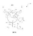
次に図1Aおよび図1Bを参照すると、無段変速機(CVT)の特定の構成要素の実施形態に関連して、座標系が画定されている。それらの座標系は、本明細書で例示目的のために示されており、本明細書で説明する実施形態に適用可能な唯一の基準系と解釈されるべきではない。CVT100の実施形態は、トラクション太陽110(概略的に線で示す)と接触するほぼ球形のトラクション遊星108を含む。さらに、トラクション遊星108は、第1の角度位置112および第2の角度位置114のそれぞれにおいて、第1のトラクションリング102および第2のトラクションリング104と接触する。図1Aでは、グローバル座標系150(すなわち、xg、yg、zg)および遊星中心座標系160(すなわち、x、y、z)が画定されている。グローバル座標系150は、概して、CVT100の長手方向軸線または主駆動軸線152に対して合わせられ、例えば、zg軸は、トラクション遊星108の配置の中心となる主駆動軸線152と一致する。遊星中心座標系160は、その原点がトラクション遊星108の幾何学的中心にあり、y軸は主駆動軸線152にほぼ垂直であり、z軸は主駆動軸線152にほぼ平行である。トラクション遊星108の各々は遊星回転軸線、すなわち遊星軸線106を有し、この遊星軸線は、x軸を中心に回転し、これにより、y−z平面に投影される傾斜角118(本明細書ではγと呼ぶこともある)を形成するように構成することができる。傾斜角118は、トラクションリング102、104の間の運動学的速度比を決定する。遊星108の各々は、遊星軸線106を中心とする回転速度を有し、この回転速度は、図1Aに遊星速度122として示されており、本明細書ではωと呼ぶこともある。典型的に、遊星軸線106は、固定することができるキャリアまたはケージ(図示せず)に動作的に結合することができる遊星軸に構造的に対応するが、他の実施形態において、遊星軸は、主駆動軸線152を中心に回転可能なキャリア(図示せず)に結合される。遊星中心座標系160において、x軸はページの平面に向けられ(すなわち図1Aでは正確に図示されておらず)、z軸は概して主駆動軸線152に平行である。例示目的のために、傾斜角118は概してyg−zg平面で画定される。Referring now to FIGS. 1A and 1B, a coordinate system is defined in connection with certain component embodiments of a continuously variable transmission (CVT). These coordinate systems are shown herein for illustrative purposes and should not be construed as the only reference system applicable to the embodiments described herein. Embodiments of the
次に図1Bを参照すると、本明細書に記載するスキュー制御システムの実施形態で使用される遊星軸線106の角度調節を示すように、遊星中心座標系160がさらに分割されている。図1Bに示すように、y−z平面に遊星軸線106を有する座標系160をx軸中心に回転させて、第1の相対座標系170(x’、y’、z’)を得ることによって、傾斜角118を導出することができる。相対座標系170において、遊星軸線106はz’軸と一致する。遊星軸線106を有する座標系170をy軸中心に回転させることにより、第2の相対座標系180(x”、y”、z”)で示されているx−z平面において、スキュー角120(本明細書ではζと呼ぶこともある)を得ることができる。スキュー角120は、遊星軸線106の角度合わせのx−z平面における投影であるとほぼみなすことができる。さらに、より具体的には、スキュー角120は、相対座標系170と180によって画定されるようなx’−z’平面における遊星軸線106の角度位置である。CVT100の一実施形態では、傾斜角118は、少なくとも部分的にスキュー角120を調節することによって制御される。 Referring now to FIG. 1B, the planetary center coordinate
次に図1Cを参照して、スキュー状態の誘発により、傾斜角118を調節する傾向がある力がどのように発生するかを説明するために、CVT100の接触する構成要素の間における特定の運動学的関係を説明する。本明細書で使用される場合、「スキュー状態」という用語は、非ゼロスキュー角120が存在するように、主駆動軸線152に対して遊星軸線106を配置することを指す。したがって、「スキュー状態の誘発」への言及は、非ゼロスキュー角120に整列させるための遊星軸線106を形成することを意味する。さらに、CVT100の特定の実施形態では、特定のスピン誘発力がトラクション遊星108に作用することに留意されたい。スピンは、当業者に周知のトラクション接触部の現象である。速やかな説明のために、スピン誘発力の効果は無視する。CVT100において、構成要素が3つの位置でトラクション遊星108と接触して、トラクション接触領域またはフリクション接触領域を形成する。図1を参照すると、第1のリング102が接点1で遊星108を駆動し、遊星108が接点2で第2のリング104に動力を伝達する。トラクション太陽110は接点3でトラクション遊星108を支持する。説明のために、3つの接点1、2、3は、図1Cにおいて、CVT100の上方の基準から見たx”−z”平面の図、または図1Aの視野Aを反映するように配置される。接触領域1、2、3は同一平面ではないので、図1Cにおいて、接触領域1、2、3をx”−z”平面で示すことができるように接触中心座標系が使用される。下付き数字1、2、および3は、接触中心座標系の特定の接触領域を示すために使用される。z1軸、z2軸、z3軸はトラクション遊星108の中心に向いている。Referring now to FIG. 1C, a specific movement between contacting components of the
次に図1Cの接触領域1を参照すると、第1のトラクションリング102の表面速度が、負のx1方向においてベクトルVr1で示され、遊星108の表面速度がベクトルVp1で示され、ベクトルVr1とVp1との間に形成される角度がほぼスキュー角120である。トラクションリング102とトラクション遊星108との間における結果として得られる相対表面速度は、ベクトルVr1/pで示される。トラクション遊星108とトラクション太陽110との間の接触領域3において、トラクション太陽110の表面速度はベクトルVsvで示され、トラクション遊星108の表面速度はベクトルVpsで示され、VsvとVpsとの間に形成される角度はスキュー角120である。トラクション遊星108とトラクション太陽110との間の相対表面速度はベクトルVsv/pで示される。同様に、接点2では、接触領域2におけるトラクション遊星108の表面速度はベクトルVp2で示され、第2のトラクションリング104の表面速度はベクトルVr2で示され、Vp2とVr2との間に形成される角度はほぼスキュー角120であり、トラクション遊星108と第2のトラクションリング104との間の相対表面速度は合成ベクトルVr2/pである。Referring now to contact
上記の運動学的関係は、接触する構成要素で力を発生させる傾向がある。図1Dは、接触領域1、2、3の各々に適用することができる一般化された代表的なトラクション曲線を示す。このグラフは、接触する構成要素の間のトラクション係数μと相対速度との関係を示す。トラクション係数μは、流体が力を伝達する能力を示す。Vr1/p等の相対速度はスキュー角120の関数であり得る。トラクション係数μは、接触領域1、2、または3における、x方向μxのトラクション係数およびy方向μyのトラクション係数のベクトル和である。一般的に、トラクション係数μは、特に、トラクション流体特性、接触領域における法線力、および接触領域におけるトラクション流体の速度の関数である。所定のトラクション流体について、トラクション係数μが最大能力に達するまで、構成要素の相対速度が増加すると共に、トラクション係数μが増加し、この後、トラクション係数μが減衰する。その結果、スキュー角120の存在下で(すなわち、スキュー状態で)、運動学的状態に起因して、トラクション遊星108の周囲の接触領域1、2、3で力が発生する。図1Cおよび図1Eを参照すると、Vr1/pは、横成分力Fs1によって、Vr1/pに平行な牽引力を発生させる。スキュー角120が増加することにより、Vr1/pが増加し、これにより、図1Dに示す一般的関係に従って力Fs1が増加する。Vsv/pは力Fssを発生させ、同様に、Vr2/pは力Fs2を発生させる。力Fs1、Fss、およびFs2が結合して、y−z平面でトラクション遊星108を中心とする正味モーメントを生成する。より具体的には、トラクションローラ108を中心とするモーメントの総和は、ΣM=R*(Fs1+Fs2+Fss)であり、式中、Rはトラクションローラ108の半径であり、力Fs1、Fs2、およびFssはy−z平面における接触力の合成成分である。本明細書ではスキュー誘発力と呼ばれることもある接触力は、上記の方程式では以下のようになる。Fs1=μy1N1、Fs2=μy2N2、Fss=μysN3であり、式中、N1、N2、N3はそれぞれの接触領域1、2、3における法線力である。トラクション係数μは、接触する構成要素の間の相対速度の関数であるので、トラクション係数μy1、μy2、およびμysは、結果として、運動学的関係によって関係付けられるようなスキュー角120の関数である。定義上、モーメントは慣性加速度であり、したがって、ここで示す実施形態では、モーメントは傾斜角加速度
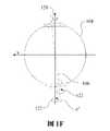
次に図1Fを参照すると、ゼロに等しい傾斜角118を有するトラクション遊星108が示されており、この傾斜角118は、(yg−zg平面において)CVT100の主駆動軸線152にほぼ平行な遊星回転軸線106で得られ、トラクション遊星108の回転速度122はz軸と同軸である。スキュー角120をx−z平面に形成して、傾斜角118の変化を引き起こすための力を発生させることができる。スキュー角120の存在下では、トラクション遊星108は、軸線z”を中心とする回転速度122を有し、傾斜角118はy−z’平面に形成される。 Referring now to FIG. 1F, a
次に図2〜図17に移り、傾斜角118の変化を引き起こすためにスキュー状態の誘発に依存するCVT用の特定の制御システムの実施形態をここで説明する。図2は、原動機50と負荷部75との間に動作的に結合されたCVT300を含むドライブ25を示す。さらに、ドライブ25はスキューベース制御システム200を含むことができる。典型的に、原動機50がCVT300に動力を送り、CVT300が負荷部75に動力を送る。原動機50は1つ以上の様々な動力発生装置であってもよく、負荷部75は1つ以上の様々な被駆動装置または被駆動構成要素であってもよい。原動機50の例は、人力、内燃機関、電気モータ等を含むが、それらに限定されない。負荷部の例は、駆動系差動アセンブリ、パワーテイクオフアセンブリ、発電機アセンブリ、ポンプアセンブリ等を含むが、それらに限定されない。いくつかの実施形態では、スキュー制御システム200は、CVT300および原動機50の動作を調節することができるか、またはCVT300および負荷部75の動作を調節することができるか、またはドライブ25の全ての要素の動作を調節することができる。図2に示す実施形態では、スキュー制御システム200は、スキュー角120の調節を用いて、CVT300の動作状態を制御し、したがって、ドライブ25の制御を調節するように構成することができる。 Turning now to FIGS. 2-17, an embodiment of a particular control system for CVT that relies on triggering a skew condition to cause a change in
次に図3〜図5Bを参照すると、一実施形態において、CVT500は、トラクション太陽510と接触するように構成されたほぼ球形の複数のトラクション遊星508を含む。さらに、トラクション遊星508は第1のトラクションリング502および第2のトラクションリング504と接触することができる。トラクションリング502、504は、図1Aに示す第1のトラクションリング102および第2のトラクションリング104とほぼ同様に配置することができる。トラクション遊星508と第1のトラクションリング502と第2のトラクションリング504とトラクション太陽510との間の接触領域は、図1A〜図1Fに示す接点1、2、および3のそれぞれとほぼ同様である。さらに、説明のために、図1A〜図1Fに関連して示す接触中心座標系および運動学的関係をCVT500に適用することができる。 3-5B, in one embodiment, the
一実施形態では、図3に関連してグローバル座標系550(すなわち、xg、yg、zg)が画定される。グローバル座標系550はグローバル座標系150とほぼ同様である。グローバル座標系550は、概して、CVT500の長手方向軸線または主駆動軸線552に対して合わせられ、例えば、zg軸は、トラクション遊星508の配置の中心となる主駆動軸線552と一致する。yg軸は主駆動軸線552に垂直である。xg軸は主駆動軸線552に垂直である。トラクション遊星508の各々は回転軸線、すなわち遊星軸線506を有し、この遊星軸線は、yg−zg平面で傾斜させ、これによって、傾斜角118(図1A)とほぼ同様の傾斜角511(γ)を形成するように構成することができる。遊星軸線506は、その一端にある第1のガイド512(図3の線で図示)に従うように構成することができる。遊星軸線506は、その第2の端部にある第2のガイド514(図3の線で図示)に従うように構成することができる。In one embodiment, a global coordinate system 550 (ie, xg , yg , zg ) is defined in connection with FIG. The global coordinate
具体的には図4を参照すると、一実施形態において、第1のガイド512および第2のガイド514を第1のステータ板516および第2のステータ板518にそれぞれ形成することができる。典型的に、遊星軸線506は、第1のガイド512および第2のガイド514のそれぞれに動作的に結合することができる遊星軸に構造的に対応する。いくつかの実施形態では、第1のステータ板516および第2のステータ板518は、CVT500の動作中に、遊星軸線506の支持部に動作可能に結合してその支持を容易にするように構成されたほぼディスク形の物体である。説明のための例示的な実施例として、図4に示す図は、xg−yg平面のステータ板518上におけるステータ板516の投影図である。xg−yg平面において、ステータ板518に対するステータ板516の角変位520を画定することができる(主駆動軸線552と一致するzg軸は図4のページの平面に垂直であり、xg軸およびyg軸の各々は主駆動軸線552に垂直である)。角変位520は本明細書において「角度β」、さらに簡潔には「β」と呼ばれることもある。CVT100に関連して使用される座標系とほぼ同様の座標系に関連して、ほぼ同様に、スキュー角120等のスキュー角をCVT500のために画定することができる。したがって、この場合、CVT500に関連してスキュー角120(ζ)が使用される。スキュー角120がゼロである場合(ζ=0)、「ゼロスキュー角状態」が遊星軸線506の当該状態として画定される。Specifically, referring to FIG. 4, in one embodiment, a
さらに、図5Aを参照すると、第1のガイド512および第2のガイド514がxg−yg平面における投影部として示されている。いくつかの実施形態では、第1のガイド512をxg−yg平面の原点に半径方向に整列させることができ、例えば、第1のガイド512はyg軸とほぼ一致することができる。一実施形態では、第2のガイド514はxg−yg平面の原点からのずれ522を有することができる。一実施例では、ずれ522は、概して、構造線519に対する直線のずれとして画定することができ、ステータ516が名目上ゼロの角変位520(β)に配置される場合、この構造線519は、第2のガイド514に平行であり、xg−yg平面の原点を通過する。第2の実施例では、第2のガイド514は、第1のガイド512に対する基本的な基準角度位置523(ψo)を有することができる。Furthermore, referring to FIG. 5A, the
さらに、図5Aおよび図5Bを参照すると、ガイド512と514が概略的に示されている。一実施形態では、ステータ518を非ゼロ角変位520(β)まで回転させることができ、この非ゼロ角変位により、ガイド514がガイド512に対して移動される(図5B)。ずれ522は、ステータ518の中央部(すなわち、xg−yg平面の原点)を中心とする半径方向のずれ525として示すことができる。ガイド514は半径方向のずれ525の接線である。具体的には図5Aを参照すると、ガイド512に対する基本的な基準角度位置523(ψo)は、ゼロ角変位520(β=0)およびゼロ傾斜角511(γ=0)で画定される。遊星軸線506の対応するゼロスキュー角状態は、xg−yg平面の投影部として見た場合に第1のガイド512と第2のガイド514との交点にある位置524に示されている。ここで、具体的には図5Bを参照すると、非ゼロ角変位520(β)について、ガイド514は、ガイド512に対する角度位置526(ψ)を有する。遊星軸線506の対応するゼロスキュー角状態は、xg−ygの平面の投影部として見た場合にガイド512とガイド514との間の交点にある位置527に示されている。位置527は、非ゼロ角変位520(β)および非ゼロ傾斜角511(γ)に関するゼロスキュー角状態の一例である。概略的に本明細書に記載するガイド512、514は、特定の実施形態に関連して以下に示すように、ステータ516、518に形成されるスロットとして設けることができることに留意されたい。このような実施例では、ガイド512、514は、それぞれの半径方向スロットおよびオフセットスロットの中央部を通過する中心線で示すことができる。図5A〜図5Cに概略的に示すように、ステータのスロットとボール508の遊星軸(またはこのような遊星軸のローラ)との接点は、概略的なガイド512、514の一方に位置する点まで減少させることができる。しかし、ステータ516、518の特定の物理的実施形態では、前記接点は半径方向線に位置しない。Further, referring to FIGS. 5A and 5B, guides 512 and 514 are schematically shown. In one embodiment, the stator 518 can be rotated to a non-zero angular displacement 520 (β) that causes the
非ゼロスキュー角120(ζ)は、別々に生じるかまたは組み合わせた2つの事象によって遊星軸線506に生じさせることができる。一方の事象は角変位520(β)の変化であり、他方の事象は傾斜角511(γ)の変化である。一実施形態では、一定の傾斜角511(γ)の角変位520(β)とスキュー角120(ζ)との関係は、他の要因の中でも、遊星軸線506の長さ、および/またはステータ516、518の半径等のCVT500の形態に依存する。一実施形態では、一定の傾斜角511(γ)の角変位520(β)とスキュー角120(ζ)との関係は、小さな角度に関して、ほぼ式β=ζで表される。角変位520(β)と角度位置526(ψ)との関係は、例えば、CVT500の形態と基本的な基準角度位置523(ψo)とに依存することができる。一実施形態では、角度位置526(ψ)は角変位520(β)に比例することができるので、式は、小さな角度に関して、式ψ=β+ψoに近似させることができる。一定の角変位520(β)について、スキュー角120(ζ)は傾斜角511(γ)に関連することもできる。例えば、スキュー角120(ζ)は、式tan(ζ)=(1/2*sin(デルタγ)*tan(ψ))により、角度位置526(ψ)と傾斜角511(デルタγ)の変化とに関連することができる。周知の小さな角度近似を前記式に適用することにより、式ζ=1/2*(デルタγ)*ψとなる。A non-zero skew angle 120 (ζ) can be caused on the
CVT500の動作中に、適切な制御入力部(図3〜図5Cには示されていないので、図7の例示的な制御入力部を参照されたい)によって、第1のステータ板516および/または第2のステータ板518を角変位520まで回転させることができる。いくつかの実施形態では、第1のステータ板516は、主駆動軸線552に対してほぼ回転不能であるように構成することができる。角変位520は最初に遊星軸線506でスキュー角120を生じさせる。上記のように、スキュー角120は遊星軸線506の傾斜角511(γ)の変化を引き起こす。遊星軸線506が傾斜するときに、遊星軸線506の端部が第1のガイド512および第2のガイド514に従う。遊星軸線506が、一実施例でゼロスキュー角状態に対応する平衡状態に向かって傾斜するのと同様の大きさに、スキュー角120が減少するように、ガイド512、514が構成される。遊星軸線506が、ゼロスキュー角状態とほぼ一致する傾斜角511(γ)に達すると、遊星軸線506の傾斜が停止する。一実施形態では、遊星軸線506の傾斜角511(γ)は少なくとも部分的に角変位520(β)に依存する。いくつかの実施形態では、傾斜角511(γ)と角変位520(β)との関係はユニークであるので、角変位520の各値(β)は、CVT500が平衡速度比状態で動作することができる傾斜角511(γ)の値に一致する。 During operation of the
平衡状態に達すると、遊星軸線506の各々はほぼゼロスキュー角状態である。CVT500の遊星軸線506、したがってトラクション遊星508はステータ516、518に独立して結合されるので、トラクション遊星508および遊星軸線506の各々自体が独立して、平衡速度比状態を安定させることができる。さらに説明すると、遊星軸線506の1つの傾斜角511(γ)が、(例えば、動作状態における外部の影響または擾乱により)平衡状態から移動する場合、遊星軸線506の端部はガイド512、514に従う。上記のように、スキュー状態が遊星軸線506で生じ、したがって、遊星軸線506が、所定の角変位520(β)の平衡状態にほぼ対応する傾斜角511(γ)に向かって傾斜する傾向になる。ガイド512、514は遊星軸線506の移動または傾斜を独立して案内する。したがって、遊星軸線506の1つの移動または傾斜は、実質的にCVT500の他の遊星軸と独立して行うことができる。 When the equilibrium state is reached, each
ガイド512、514の構成は、CVT500を平衡状態に安定させる能力に影響を与える。第1のトラクションリング504の所定の回転方向では、図5Aに示すガイド512、514の構成により、CVT500の安定した動作が得られる。例えば、CVT500の、角変位520(β)に対応する所望の速度比を維持することができる。概して図1A〜図1Fに関連して定義された符号の例によれば、所定の角変位520(β)について、傾斜角511の正の変化(γ)がスキュー角の正の変化を生じさせ、その逆もまた同様であることが理解できる。したがって、各遊星軸線506は、図5Aに示すガイド512、514の関連する構成が設けられる場合に安定して動作することができる。 The configuration of
ここで図5Cを参照すると、一実施形態において、ガイド5121およびガイド5141はガイド512、514の機能とほぼ同様であり得るが、ガイド5121、5141は、xg−yg平面に関連する基本的な基準角度位置523(ψo)に向かう方向とはほぼ反対側である基本的な基準角度位置5231(すなわち、反対の符号)に配置される。第1のリング504の等しい回転方向、したがってトラクション遊星508の回転方向を想定すると、ガイド5121、5141の構成は、少なくともいくつかの実施例において、CVT500の不安定な動作をもたらす場合がある。例えば、傾斜角511の正の変化(γ)は負のスキュー角を生じさせ、その逆もまた同様であるので、CVT500の角変位520(β)に対応する所望の速度比を維持することができない。したがって、遊星軸線506の1つを傾斜させる動作における擾乱により、遊星軸線506は、例えば機械的ストッパ(図示せず)によって制限されるまで傾斜させられる。Referring now to FIG. 5C, in one embodiment,
次に図6Aを参照すると、一実施形態において、例えば、CVT500に結合されたパワーエレクトロニクスハードウェアと通信するマイクロプロセッサで、スキューベース制御プロセス600を実行することができる。スキューベース制御プロセス600は状態602から開始する。次に、スキューベース制御プロセス600は状態604に進み、ここで、CVT500の所望の速度比(SR)の設定値が受信される。スキューベース制御プロセス600は状態606に続き、ここで、例えば第1のステータ516の角変位520が決定される。次に、スキューベース制御プロセス600はアクチュエータサブプロセス608に移り、ここで、角変位520が例えばステータ516に適用される。アクチュエータサブプロセス608が終了すると、スキューベース制御プロセス600は状態609に進み、ここで、CVT500の実際のSRが測定される。一実施形態では、CVT500の実際のSRは、例えばトラクションリング502と504の速度、またはCVT500に対する入力速度および出力速度を示す他の任意の成分を測定することによって決定することができる。いくつかの実施形態では、実際のSRは、少なくとも部分的に目標出力速度状態に基づいて、または少なくとも部分的に目標入力速度状態に基づいて計算することができる。他の実施形態では、CVT500の実際のSRは、遊星軸線506の傾斜角を測定することによって決定することができる。さらに他の実施形態では、CVT500の実際のSRは、CVT500の実際のトルク比を測定することによって決定することができる。CVT500の実際のトルク比は、例えばトラクションリング502と504のトルク、またはCVT500に対する入力トルクおよび出力トルクを示す他の任意の成分を測定することによって決定することができる。次に、スキューベース制御プロセス600は決定状態610に進み、ここで、測定された速度比を所望の速度比設定値と比較し、これによって比較値を形成する。測定された速度比が所望の速度比設定値に等しくない場合、スキューベース制御プロセス600は状態606に戻る。測定された速度比が所望の速度比設定値に等しい場合、スキューベース制御プロセス600は終了状態612に進む。いくつかの実施形態では、スキューベース制御プロセス600は開ループで動作するように構成され、このような場合、状態609と610はサブプロセス608に含まれない。 Referring now to FIG. 6A, in one embodiment, the skew-based
図6Bを参照すると、一実施形態において、状態606では、曲線607で表すことができるルックアップテーブルを使用することができる。曲線607は、例えばCVT500の角変位520(β)と速度比との例示的な関係を示す。曲線607は式y=Ax2−Bx+Cで表すことができ、式中、yは角変位520(β)であり、xは速度比である。一実施形態では、A、B、およびCの値はそれぞれ0.5962、−4.1645、および3.536である。いくつかの実施形態では、A、B、およびCの値はそれぞれ0.5304、−4.0838、および3.507である。他の実施形態では、A、B、およびCの値は、CVT500の寸法および形状、例えば、特に、ステータ516と518のガイド512と514の位置、遊星軸線506の長さ、およびトラクションリング502と504の寸法に関連する。いくつかの実施形態では、当該アクチュエータサブプロセス608は開ループで動作するように構成され、このような場合、状態619と620はサブプロセス608に含まれない。Referring to FIG. 6B, in one embodiment, in
図6Cを参照すると、一実施形態において、アクチュエータサブプロセス608は状態614から開始し、状態615に進むことができ、ここで、角変位520(β)の設定値が受信される。アクチュエータサブプロセス608は状態616に進み、ここで、アクチュエータ指令信号が少なくとも部分的に角変位520(β)に基づいて決定される。一実施形態では、ルックアップテーブルを使用して、角変位520(β)の設定値をアクチュエータ指令信号に変換することができる。いくつかの実施形態では、アクチュエータ指令信号は電圧または電流であり得る。他の実施形態では、アクチュエータ指令信号はケーブルまたはリンク機構の位置の変化であり得る。いくつかの実施形態では、アルゴリズムを使用して、角変位520(β)の設定値からアクチュエータ指令信号を導出することができる。次に、アクチュエータサブプロセス608は状態617に進み、ここで、アクチュエータ指令信号が、アクチュエータおよびそれに関連するハードウェアに送信される。一実施形態では、標準シリアル通信プロトコルを使用して、指令信号をアクチュエータハードウェアに送信することができる。いくつかの実施形態では、ケーブルまたはリンク機構を使用して、指令信号をアクチュエータハードウェアに送信することができる。次に、アクチュエータサブプロセス608は状態618に進み、ここで、ステータ、例えばステータ516が回転される。その次に、アクチュエータサブプロセス608は状態619に進み、ここで、角変位520(β)が測定される。次に、アクチュエータサブプロセス608は決定状態620に進み、ここで、測定された角変位520(β)がその設定値と比較される。測定された角変位520(β)がその設定値に等しくない場合、アクチュエータサブプロセス608は状態616に戻る。測定された角変位520(β)がその設定値に等しい場合、アクチュエータサブプロセス608は状態622で終了し、ここで、スキューベース制御プロセス600は、図6Aに関連して上述したような状態609に続くことができる。いくつかの実施形態では、アクチュエータサブプロセス608は開ループで動作するように構成され、このような場合、状態619と620はサブプロセス608に含まれない。 Referring to FIG. 6C, in one embodiment, the
次に図7を参照すると、一実施形態において、CVT1000は、バリエータアセンブリ1004に動作可能に結合されたスキューベース制御システム1002を含むことができる。一実施形態では、バリエータアセンブリ1004は、ほぼ球形の複数のトラクション遊星1008の半径方向内側に配置されかつそれらと接触するトラクション太陽1006を含む。トラクション太陽1006は、軸受1011を設けることによって主軸1010を中心に回転するように構成することができる。一実施形態では、トラクション太陽1006は、主軸1010および軸受1011に結合されるクリップ1012により、主軸1010に対して軸方向に固定される。 Referring now to FIG. 7, in one embodiment, the
一実施形態では、各トラクション遊星1008には一組の遊星軸1009Aと1009Bが設けられ、これらの遊星軸は、それらのそれぞれのトラクション遊星1008のための傾斜可能な回転軸線を提供するように構成される。遊星軸1009Aと1009Bはトラクション遊星1008と共に回転するように構成することができる。遊星車軸1009Aと1009Bはトラクション遊星1008の中心軸線にほぼ整列される。他の実施形態では、トラクション遊星1008は中央孔を有するように構成することができ、トラクション遊星1008は軸受を介して遊星軸(図示せず)に動作可能に結合されることができ、この結果、遊星軸はほぼ回転不能であるように構成される。トラクション遊星1008の各々は第1のステータ1014および第2のステータ1016に動作可能に結合される。第1のステータ1014および第2のステータ1016を主軸1010と同軸に配置することができる。 In one embodiment, each
CVT1000の一実施形態では、入力ドライバ1018を主軸1010と同軸に配置することができる。入力ドライバ1018は、例えば、スプロケット、プーリ、または他の適切な継手から入力動力を受け取るように構成することができる。一実施形態では、入力ドライバ1018は、第1の軸方向力発生アセンブリ1020に結合されるねじり板1019に結合される。軸方向力発生アセンブリ1020は、トラクションリング102(図1A)の機能とほぼ同様であり得る第1のトラクションリング1022に動作可能に結合される。第1のトラクションリング1022はトラクション遊星1008の各々に接触するように構成される。第2のトラクションリング1024はトラクション遊星1008の各々に接触するように構成される。第2のトラクションリング1024はトラクションリング104(図1A)の機能とほぼ同様であり得る。一実施形態では、第2のトラクションリング1024は第2の軸方向力発生アセンブリ1026に結合される。第2の軸方向力発生アセンブリ1026は第1の軸方向力発生アセンブリ1020とほぼ同様であり得る。特定の実施形態では、軸方向力発生アセンブリ1020と1026は、概してPCT特許出願PCT/US2007/023315号明細書に記載されているクランプ力発生機構とほぼ同様であり得る。 In one embodiment of the
CVT1000の動作中に、例えばスプロケットを介して、入力動力を入力ドライバ1018に伝達することができる。入力ドライバ1018は、ねじり板1019を介して動力を第1の軸方向力発生機1020に伝達することができる。第1の軸方向力発生機1020は、第1のトラクションリング1022とトラクション遊星1008の各々との間のトラクションインタフェースまたはフリクションインタフェースを介して、動力をトラクション遊星1008に伝達することができる。トラクション遊星1008は第2のトラクションリング1024および第2の軸方向力発生機1026を介して、動力をハブシェル1028に伝達する。入力速度対出力速度比のシフト、したがって、入力トルク対出力トルク比のシフトは、トラクション遊星1008の回転軸線を傾斜させることによって実現される。一実施形態では、トラクション遊星1008の回転軸線の傾斜は、第1のステータ516(図4〜図5C)とほぼ同様であり得る第1のステータ1014を回転させることによって実現される。 During operation of the
ここで図8を参照すると、一実施形態において、CVT2000はCVT1000とほぼ同様であり得る。説明では、CVT1000とCVT2000との違いのみを説明する。一実施形態では、CVT2000は、トラクション遊星1008の各々の半径方向内側に配置されかつそれらと接触するトラクション太陽2007を含む。トラクション太陽2007は、図8のページの平面の断面図で見た場合に物体の外周を中心としてV字形状に形成することができるほぼ円筒状の物体である。トラクション太陽2007は、第1の位置2008および第2の位置2009のそれぞれにおいてトラクション遊星1008の各々に接触するように構成することができる。接点3に関連して示されている接触中心座標系および運動学的関係(図1A〜図1F)を接触位置2008と2009に同様に適用することができる。CVT2000の動作中に、トラクション太陽2007は、接触位置2008と2009で軸方向力の釣り合いをとることによってほぼ軸方向に固定される。さらに、いくつかの実施形態では、第1のリング1022および第2のリング1024は、十分な半径方向の運動学的拘束を遊星1008に与えるように構成され、このような実施形態では、トラクション太陽2007および軸受1011を、本明細書に記載するCVTの様々な実施形態から排除することができる。 Referring now to FIG. 8, in one embodiment,
図9を参照すると、一実施形態において、スキューベース制御システム1002は、ステータ駆動部1032に結合するように構成することができるレバーアーム1030を含むことができる。ステータ駆動部1032は、例えば、複数のドエルあるいは他の適切な締結具または継手(図示せず)を介して第1のステータ板1014に結合することができる。一実施形態では、ステータ駆動部1032はほぼ中空円筒状の物体であり得る。ステータ駆動部1032の一端には、第1のステータ板1014へのステータ駆動部1032の結合を容易にするように構成されるフランジ1031を設けることができる。ステータ駆動部1032には、例えば、軸受を保持するためのクリップ1035を受け入れるように構成することができる溝を設けることができる。 Referring to FIG. 9, in one embodiment, the skew-based
一実施形態では、第1のステータ板1014は主軸1010に対して回転するように構成することができる。例えば、ブッシュ1033を第1のステータ板1014におよびステータ駆動部1032に結合することができる。ブッシュ1033を主軸1010の周囲に同軸に配置することができる。一実施形態では、ナット1034は主軸1010と協働してブッシュ1033を軸方向に保持するように構成することができる。いくつかの実施形態では、第2のステータ板1016は、スプライン1035、または他の適切なトルク伝達継手を介して主軸1010に結合することができ、その結果、第2のステータ板1016は主軸1010に対してほぼ回転不能である。 In one embodiment, the
CVT1000の動作中に、主軸1010を中心としてレバーアーム1030を回転させ、これによって、主軸1010を中心とするステータ駆動部1032の角度回転を生じさせることができる。レバーアーム1030は、リンク機構またはケーブル(図示せず)によって手動で回転させることができる。いくつかの実施形態では、レバーアーム1030をDCモータまたはサーボアクチュエータ等の電子アクチュエータ(図示せず)に動作可能に結合することができる。いくつかの実施形態では、レバーアーム1030を油圧アクチュエータ(図示せず)に動作可能に結合することができる。他の実施形態では、ステータ駆動部1032を上記アクチュエータのいずれかのようなアクチュエータに直接結合することができる。ステータ駆動部1032の角度回転により、角変位(β)が、第2のステータ板1016に対する第1のステータ板1014に与えられる。CVT500に関連して先に記載したように、第2のステータ板1016に対する第1のステータ板1014の角度回転により、トラクション遊星1008の回転軸線の傾斜を容易にすることができる。 During the operation of the
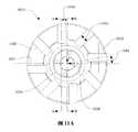
次に図10〜図13を参照すると、一実施形態において、第1のステータ板1014は、中央孔を有するほぼディスク形の物体であり得る。いくつかの実施形態では、第1のステータ板1014には、中央孔を中心に形成されるハブ1036を設けることができる。ハブ1036には、ステータ駆動部1032への第1のステータ板1014の結合を容易にすることができる複数の孔1038を設けることができる。半径方向にオフセットされた複数のスロット1040を第1のステータ板1014の面に形成することができる。半径方向にオフセットされたスロット1040は、例えば、玉軸1009の各々に動作可能に結合される複数のローラ1042(図9参照)との接触によって、トラクション遊星1008の支持を容易にするように構成することができる。第2のステータ板1016には複数の半径方向スロット1044を設けることができる。半径方向スロット1044はローラ1042に結合するように構成することができる。図10は、半径方向スロット1044に対する、半径方向にオフセットされたスロット1040の例示的な構成を示す。説明のために、グローバル座標1047(図9)がCVT1000に適用される。したがって、半径方向スロット1044は、xg−yg平面における第1のステータ板1014の投影部として見ることができる。半径方向スロット1044は図10の破線で示されている。Referring now to FIGS. 10-13, in one embodiment, the
具体的には図11Aおよび図11Bを参照すると、一実施形態において、半径方向にオフセットされたスロット1040および半径方向スロット1044は幅1046を有する。幅1046をローラ1042の外径に合うように寸法決めすることができる。図10に示す実施形態では、半径方向スロット1044が第2のステータ板1016を中心に配置されるので、半径方向にオフセットされたスロット1040は、xg−ygの平面への、半径方向にオフセットされたスロット1040および半径方向スロット1044の投影部に見られるように、半径方向スロット1044と整列しない(すなわちオフセットされる)。断面線A−AとB−Bに依存する図11には、直線のずれ1048の大きさが示されている。断面線A−Aは、半径方向にオフセットされたスロット1040をほぼ二等分し、この場合、二等分部分は幅1046のほぼ半分である。断面線B−Bは第1のステータ板1014の中心線にほぼ整列する。断面線B−Bは主駆動軸線zg(図9)に垂直な線である。断面線A−Aは断面線B−Bに平行な線である。代わりに、構造線1050および中心線1051を画定することによって、角度ずれ1049を有するように、半径方向にオフセットされたスロット1040を示してもよい。中心線1051は第1のステータ板1014の直径に関連して構成することができる。遊星軸1009が、ゼロにほぼ等しい傾斜角である場合、構造線1050は、便宜上、遊星軸1009の中央部と一致する半径方向位置にあるように示される。角度ずれ1049は、中心線1051と、構造線1050に沿っており半径方向にオフセットされたスロット1040の中央部との間の角変位として画定することができ、この場合、半径方向にオフセットされたスロット1040の中央部は幅1046のほぼ半分である。一実施形態では、角度ずれ1049は約0度〜45度の範囲にある。いくつかの実施形態では、角度ずれ1049は、5〜20度であり、好ましくは8度、9度、10度、11度または12度であり得る。Specifically, referring to FIGS. 11A and 11B, in one embodiment, the radially offset
次に図12および図13を参照すると、一実施形態において、第1のステータ板1014には、中央孔の周囲に配置されるシフトストッパ延長部1052を設けることができる。第1のステータ板1014には、ほぼトロイダル型のクリアランスカット1054を設けることができる。クリアランスカット1054を第1のステータ板1014の面に形成することができる。クリアランスカット1054は、図13の平面で見た場合に、ほぼ湾曲状のプロファイルを有することができる。同様に、半径方向にオフセットされたスロット1040のバレイ1041および/または壁1043には、図12の平面で見た場合に、ほぼ湾曲状のプロファイルを設けることができる。CVT1000の動作中、半径方向にオフセットされたスロット1040がローラ1042を案内する。シフトストッパ延長部1052は、半径方向にオフセットされたスロット1040におけるローラ1042の軌道に対して機械的制限を与えることができる。いくつかの実施形態では、シフトストッパ延長部1052を第1のステータ板1014の半径方向外側の周囲に形成することができる。 Referring now to FIGS. 12 and 13, in one embodiment, the
次に図14および図15を参照すると、一実施形態において、第2のステータ板1016は、中央孔1056を有するほぼディスク形の物体であり得る。中央孔1056は、例えば、スプライン、ローレット、または溶接による主軸1010への第2のステータ板1016の結合を容易にするように構成することができる。半径方向スロット1044は中央孔1056の周囲に角度を付けて配置することができる。いくつかの実施形態では、半径方向スロット1044は、ステータ板1016の周囲の近傍からまたはその近傍において、中央孔1056に向かって第2のステータ板1016に延びることができる。半径方向スロット1044には、図15の平面で見た場合に、湾曲状プロファイルを設けることができる。一実施形態では、第2のステータ板1016にはシフトストッパ延長部1057を設けることができる。シフトストッパ延長部1057は、中央孔1056を中心に半径方向に形成され、そこから軸方向に延びることができる。シフトストッパ延長部1057はシフトストッパ延長部1052と同様に構成することができる。 14 and 15, in one embodiment, the
次に図16および図17を参照すると、一実施形態において、遊星軸1009には、クリップ1072を受け入れるように構成される溝1070を設けることができる。クリップ1072は遊星軸1009へのローラ1042の結合を容易にすることができる。一実施形態では、表面1074を遊星軸1009に設けて、軸受1076の支持を行うことができる。軸受1076はローラ1042の内径に結合するように構成することができる。いくつかの実施形態では、軸受1076がローラ1042に圧入される。他の実施形態では、ローラ1042は玉軸受1077を受け入れるように構成することができる。軸受面1078は、遊星軸1009への軸受1077の結合を容易にするために遊星軸1009に設けることができる。 Referring now to FIGS. 16 and 17, in one embodiment, the
さらに図16および図17を参照すると、一実施形態において、ローラ1042は、中央孔を有するほぼ円筒状の物体である。中央孔は軸受1076または軸受1077を受け入れるように構成することができる。ローラ1042には円筒体の冠状の外周を設けることができる。冠状の外周は、第1のステータ板1014および第2のステータ板1016への遊星軸1009の結合を容易にするように構成される。 Still referring to FIGS. 16 and 17, in one embodiment,
上記の説明が特定の構成要素またはサブアセンブリに関する寸法を提供していることに留意されたい。言及した寸法または寸法範囲は、最良の形態等の特定の法的要件に可能な限り最良に従うように意図される。しかし、本明細書に記載の本発明の範囲は、特許請求の範囲の文言によってのみ決定されるべきであり、したがって、指定の寸法またはその範囲を特徴とする請求項がない限り、言及した寸法のいずれもが、本発明の実施形態を限定するとみなされるべきではない。 Note that the above description provides dimensions for particular components or subassemblies. The dimensions or dimension ranges mentioned are intended to best follow specific legal requirements such as best mode. However, the scope of the invention described herein should be determined only by the language of the claims, and thus, unless stated to the extent characterized by a specified dimension or range thereof, the dimensions referred to. None of these should be considered as limiting embodiments of the present invention.
上記の説明は、本発明の特定の実施形態を詳細に説明している。しかし、上記の文面がいかに詳細に見えようと、本発明を多くの方法で実施できることが理解されるであろう。さらに上記のように、本発明の特定の特徴または態様を説明する場合の特定の用語の使用は、その用語が関連する本発明の特徴または態様の任意の具体的な特性を含むものに限定されるように、その用語が本明細書において再定義されていることを意味するものとみなされるべきではないことに留意されたい。 The foregoing description details certain embodiments of the invention. It will be understood, however, that no matter how detailed the above text appears, the invention can be implemented in many ways. Furthermore, as described above, the use of a particular term in describing a particular feature or aspect of the invention is limited to including any specific characteristic of the feature or aspect of the invention to which the term relates. As such, it should be noted that the term should not be taken to imply that it has been redefined herein.
Claims (17)
Translated fromJapanese前記主駆動軸線と同軸の第1のステータ板であって、前記第1のステータ板が、半径方向にオフセットされた複数のスロットを有し、傾斜可能な各軸線が他の軸線から独立して案内されるように、前記半径方向にオフセットされた複数のスロットが構成される第1のステータ板と、
前記主駆動軸線と同軸の第2のステータ板であって、前記第2のステータ板が複数の半径方向スロットを有し、前記複数の半径方向スロットが前記傾斜可能な回転軸線を独立して案内するように構成される第2のステータ板と、
を備え、
傾斜可能な各軸線は、前記第1ステータ板側の第1端部及び前記第2ステータ板側の第2端部を有し、各第1端部は、単一のスロットに案内されるように構成され、
前記第1のステータ板が前記第2のステータ板に対して回転するように構成される無段変速機(CVT)。A continuously variable transmission (CVT) having a plurality of traction planets each angled about a main drive axis, each having a tiltable axis of rotation, the CVT comprising:
A first stator plate coaxial with the main drive axis, wherein the first stator plate has a plurality of radially offset slots, and each of the tiltable axes is independent of the other axes. A first stator plate comprising a plurality of radially offset slots to be guided;
A second stator plate coaxial with the main drive axis, wherein the second stator plate has a plurality of radial slots, and the plurality of radial slots independently guide the tiltable axis of rotation. A second stator plate configured to:
With
Each tiltable axis has a first end on the first stator plate side and a second end on the second stator plate side, and each first end is guided in a single slot. Composed of
A continuously variable transmission (CVT) configured such that the first stator plate rotates relative to the second stator plate.
中央部を有するほぼディスク形の物体と、
前記中央部の周囲に角度を付けて配置されている半径方向にオフセットされた複数のガイドであって、前記半径方向にオフセットされたガイドの各々が、前記ディスク形の物体の中心線からオフセットされた直線部を有する半径方向にオフセットされた複数のガイドと、
を備えるステータ板。A stator plate for a continuously variable transmission (CVT) having a plurality of traction planets,
A substantially disc-shaped object having a central portion;
A plurality of radially offset guides disposed at an angle around the central portion, each of the radially offset guides being offset from a centerline of the disk-shaped object. A plurality of radially offset guides having straight line portions;
A stator plate.
前記CVTの主駆動軸線の周囲に同軸に配置された第1のステータ板であって、前記第1のステータ板が各トラクション遊星に動作可能に結合され、前記第1のステータ板が、前記第1のステータ板の中央部の周囲に角度を付けて配置されている半径方向にオフセットされた複数のスロットを有し、前記半径方向にオフセットされた複数のスロットの各々が、前記第1のステータ板の中心線からオフセットされた直線部を有する第1のステータ板と、
前記CVTの主駆動軸線の周囲に同軸に配置された第2のステータ板であって、前記第2のステータ板が複数の半径方向スロットを有し、前記複数の半径方向スロットが前記第2のステータ板の中央部の周囲に角度を付けて配置され、前記複数の半径方向スロットの各々が前記第2のステータ板の前記中央部にほぼ半径方向に整列される第2のステータ板と、
前記第1および第2のステータ板の少なくとも一方に動作可能に結合されたアクチュエータであって、前記第1のステータ板と前記第2のステータ板との間で相対的回転を与えるように構成されるアクチュエータと、
を備える無段変速機(CVT)。A continuously variable transmission (CVT) having a plurality of traction planets each having a tiltable axis of rotation,
A first stator plate coaxially disposed around a main drive axis of the CVT, wherein the first stator plate is operably coupled to each traction planet, and the first stator plate is A plurality of radially offset slots disposed at an angle around a central portion of one stator plate, each of the plurality of radially offset slots being the first stator. A first stator plate having a straight portion offset from the center line of the plate;
A second stator plate coaxially disposed about a main drive axis of the CVT, wherein the second stator plate has a plurality of radial slots, and the plurality of radial slots are the second A second stator plate disposed at an angle around a central portion of the stator plate, wherein each of the plurality of radial slots is substantially radially aligned with the central portion of the second stator plate;
An actuator operably coupled to at least one of the first and second stator plates, the actuator being configured to provide relative rotation between the first stator plate and the second stator plate. An actuator
A continuously variable transmission (CVT).
傾斜可能な回転軸線を各々が有する複数のトラクション遊星と、
前記CVTの主駆動軸線に垂直な線に整列された第1のガイドであって、前記傾斜可能な回転軸線の第1端部に作用するように構成される第1のガイドと、
前記CVTの前記主駆動軸線に垂直な線に対し半径方向にオフセットされた第2のガイドであって、前記傾斜可能な回転軸線の第2端部に作用するように構成される第2のガイドと、
を備え、
前記傾斜可能な各回転軸線の前記第2端部は、単一の第2のガイドに案内されるように構成されるボール遊星無段変速機(CVT)。A ball planetary continuously variable transmission (CVT),
A plurality of traction planets each having a tiltable axis of rotation;
A first guide aligned with a line perpendicular to the main drive axis of the CVT, the first guide configured to act on afirst end of the tiltable rotation axis;
A second guide radially offset with respect to a line perpendicular to the main drive axis of the CVT, the second guide configured to act on asecond end of the tiltable axis of rotation When,
Equipped witha,
Wherein the second end of each tiltable axis of rotation, the ball planetary continuously variable transmission thatwill be configured to be guided to a single second guide (CVT).
請求項11に記載のCVT。The second guide is aligned with a line that is parallel to a line perpendicularto the main drive axis of the CVT;
The CVT according to claim 11.
前記主駆動軸線と同軸の第1のステータ板であって、前記第1のステータ板が、半径方向にオフセットされた複数のスロットを有し、傾斜可能な各軸線が他の軸線から独立して案内されるように、前記半径方向にオフセットされた複数のスロットが構成される第1のステータ板と、 A first stator plate coaxial with the main drive axis, wherein the first stator plate has a plurality of radially offset slots, and each of the tiltable axes is independent of the other axes. A first stator plate comprising a plurality of radially offset slots to be guided;
前記主駆動軸線と同軸の第2のステータ板であって、前記第2のステータ板が複数の半径方向スロットを有し、前記複数の半径方向スロットが前記傾斜可能な回転軸線を独立して案内するように構成される第2のステータ板と、 A second stator plate coaxial with the main drive axis, wherein the second stator plate has a plurality of radial slots, and the plurality of radial slots independently guide the tiltable axis of rotation. A second stator plate configured to:
を備え、With
前記第1のステータ板が前記第2のステータ板に対して回転するように構成され、 The first stator plate is configured to rotate relative to the second stator plate;
前記半径方向にオフセットされた複数のスロットの各々は、前記第1ステータ板の中心線からオフセットされた直線部を有する、 Each of the plurality of slots offset in the radial direction has a straight portion offset from a center line of the first stator plate.
無段変速機(CVT)。Continuously variable transmission (CVT).
傾斜可能な回転軸線を各々が有する複数のトラクション遊星と、 A plurality of traction planets each having a tiltable axis of rotation;
前記CVTの主駆動軸線に垂直な線に整列された第1のガイドであって、前記傾斜可能な回転軸線に作用するように構成される第1のガイドと、 A first guide aligned with a line perpendicular to the main drive axis of the CVT, the first guide configured to act on the tiltable rotation axis;
前記CVTの前記主駆動軸線に垂直な線に対し半径方向にオフセットされた第2のガイドであって、前記傾斜可能な回転軸線に作用するように構成される第2のガイドと、 A second guide that is radially offset with respect to a line perpendicular to the main drive axis of the CVT, the second guide configured to act on the tiltable axis of rotation;
を備え、With
前記第2のガイドは、前記CVTの前記主駆動軸線に垂直な線に平行である線に整列されている、 The second guide is aligned with a line that is parallel to a line perpendicular to the main drive axis of the CVT;
ボール遊星無段変速機(CVT)。Ball planetary continuously variable transmission (CVT).
Applications Claiming Priority (3)
| Application Number | Priority Date | Filing Date | Title |
|---|---|---|---|
| US12/198,402US8469856B2 (en) | 2008-08-26 | 2008-08-26 | Continuously variable transmission |
| US12/198,402 | 2008-08-26 | ||
| PCT/US2008/074496WO2010024809A1 (en) | 2008-08-26 | 2008-08-27 | Continuously variable transmission |
Related Child Applications (1)
| Application Number | Title | Priority Date | Filing Date |
|---|---|---|---|
| JP2014040692ADivisionJP5852156B2 (en) | 2008-08-26 | 2014-03-03 | Continuously variable transmission |
Publications (2)
| Publication Number | Publication Date |
|---|---|
| JP2012501418A JP2012501418A (en) | 2012-01-19 |
| JP5492894B2true JP5492894B2 (en) | 2014-05-14 |
Family
ID=40549963
Family Applications (4)
| Application Number | Title | Priority Date | Filing Date |
|---|---|---|---|
| JP2011524950AActiveJP5492894B2 (en) | 2008-08-26 | 2008-08-27 | Continuously variable transmission |
| JP2014040692AActiveJP5852156B2 (en) | 2008-08-26 | 2014-03-03 | Continuously variable transmission |
| JP2015236532AActiveJP6220843B2 (en) | 2008-08-26 | 2015-12-03 | Continuously variable transmission |
| JP2017192347AActiveJP6453969B2 (en) | 2008-08-26 | 2017-10-02 | Continuously variable transmission |
Family Applications After (3)
| Application Number | Title | Priority Date | Filing Date |
|---|---|---|---|
| JP2014040692AActiveJP5852156B2 (en) | 2008-08-26 | 2014-03-03 | Continuously variable transmission |
| JP2015236532AActiveJP6220843B2 (en) | 2008-08-26 | 2015-12-03 | Continuously variable transmission |
| JP2017192347AActiveJP6453969B2 (en) | 2008-08-26 | 2017-10-02 | Continuously variable transmission |
Country Status (13)
| Country | Link |
|---|---|
| US (4) | US8469856B2 (en) |
| EP (3) | EP2511573B1 (en) |
| JP (4) | JP5492894B2 (en) |
| CN (3) | CN108953532B (en) |
| BR (1) | BRPI0823021A2 (en) |
| CA (2) | CA2734982C (en) |
| DK (2) | DK2511573T3 (en) |
| ES (2) | ES2525588T3 (en) |
| MX (2) | MX351065B (en) |
| PL (2) | PL2511573T3 (en) |
| RU (1) | RU2499932C2 (en) |
| TW (3) | TWI601893B (en) |
| WO (1) | WO2010024809A1 (en) |
Families Citing this family (123)
| Publication number | Priority date | Publication date | Assignee | Title |
|---|---|---|---|---|
| US7011600B2 (en) | 2003-02-28 | 2006-03-14 | Fallbrook Technologies Inc. | Continuously variable transmission |
| WO2006041718A2 (en) | 2004-10-05 | 2006-04-20 | Fallbrook Technologies, Inc. | Continuously variable transmission |
| WO2007070167A2 (en) | 2005-10-28 | 2007-06-21 | Fallbrook Technologies Inc. | Electromotive drives |
| PL1954959T3 (en) | 2005-11-22 | 2013-10-31 | Fallbrook Ip Co Llc | Continuously variable transmission |
| CN102221073B (en)* | 2005-12-09 | 2013-03-27 | 福博科技术公司 | Continuously variable transmission |
| EP1811202A1 (en)* | 2005-12-30 | 2007-07-25 | Fallbrook Technologies, Inc. | A continuously variable gear transmission |
| US7882762B2 (en) | 2006-01-30 | 2011-02-08 | Fallbrook Technologies Inc. | System for manipulating a continuously variable transmission |
| WO2007106874A2 (en) | 2006-03-14 | 2007-09-20 | Autocraft Industries, Inc. | Improved wheelchair |
| CN102269055B (en) | 2006-06-26 | 2013-08-28 | 福博科技术公司 | Continuously variable transmission |
| PL2089642T3 (en) | 2006-11-08 | 2013-09-30 | Fallbrook Ip Co Llc | Clamping force generator |
| EP2125469A2 (en)* | 2007-02-01 | 2009-12-02 | Fallbrook Technologies Inc. | System and methods for control of transmission and/or prime mover |
| US20100093479A1 (en) | 2007-02-12 | 2010-04-15 | Fallbrook Technologies Inc. | Continuously variable transmissions and methods therefor |
| TWI461615B (en) | 2007-02-16 | 2014-11-21 | Fallbrook Ip Co Llc | Infinitely variable transmissions, continuously variable transmissions, methods, assemblies, subassemblies, and components therefor |
| EP2142826B1 (en)* | 2007-04-24 | 2015-10-28 | Fallbrook Intellectual Property Company LLC | Electric traction drives |
| US8641577B2 (en)* | 2007-06-11 | 2014-02-04 | Fallbrook Intellectual Property Company Llc | Continuously variable transmission |
| CN103697120B (en) | 2007-07-05 | 2017-04-12 | 福博科技术公司 | Continuously variable transmission |
| CN103939602B (en) | 2007-11-16 | 2016-12-07 | 福博科知识产权有限责任公司 | Controllers for variable speed drives |
| US8321097B2 (en) | 2007-12-21 | 2012-11-27 | Fallbrook Intellectual Property Company Llc | Automatic transmissions and methods therefor |
| US8313405B2 (en)* | 2008-02-29 | 2012-11-20 | Fallbrook Intellectual Property Company Llc | Continuously and/or infinitely variable transmissions and methods therefor |
| US8317651B2 (en) | 2008-05-07 | 2012-11-27 | Fallbrook Intellectual Property Company Llc | Assemblies and methods for clamping force generation |
| CN102112778B (en) | 2008-06-06 | 2013-10-16 | 福博科技术公司 | Infinitely variable transmission, continuously variable transmission, methods, assemblies, subassemblies and components therefor |
| EP2304272B1 (en) | 2008-06-23 | 2017-03-08 | Fallbrook Intellectual Property Company LLC | Continuously variable transmission |
| CA2732668C (en) | 2008-08-05 | 2017-11-14 | Fallbrook Technologies Inc. | Methods for control of transmission and prime mover |
| US8469856B2 (en) | 2008-08-26 | 2013-06-25 | Fallbrook Intellectual Property Company Llc | Continuously variable transmission |
| ES2423934T3 (en)* | 2008-10-14 | 2013-09-25 | Fallbrook Intellectual Property Company Llc | Continuously variable transmission |
| US8167759B2 (en) | 2008-10-14 | 2012-05-01 | Fallbrook Technologies Inc. | Continuously variable transmission |
| ES2439647T3 (en)* | 2009-04-16 | 2014-01-24 | Fallbrook Intellectual Property Company Llc | Stator set and speed change mechanism for a continuously variable transmission |
| US8512195B2 (en)* | 2010-03-03 | 2013-08-20 | Fallbrook Intellectual Property Company Llc | Infinitely variable transmissions, continuously variable transmissions, methods, assemblies, subassemblies, and components therefor |
| US8888643B2 (en) | 2010-11-10 | 2014-11-18 | Fallbrook Intellectual Property Company Llc | Continuously variable transmission |
| AU2012240435B2 (en) | 2011-04-04 | 2016-04-28 | Fallbrook Intellectual Property Company Llc | Auxiliary power unit having a continuously variable transmission |
| US9347532B2 (en) | 2012-01-19 | 2016-05-24 | Dana Limited | Tilting ball variator continuously variable transmission torque vectoring device |
| CN104302949B (en)* | 2012-01-23 | 2017-05-03 | 福博科知识产权有限责任公司 | Infinitely variable continuously variable transmission, continuously variable continuously variable transmission, method, assembly, subassembly, and parts thereof |
| CN104204615B (en) | 2012-02-15 | 2017-10-24 | 德纳有限公司 | Transmission device and the power train with tilt ball speed changer infinitely variable speed transmission |
| JP5761445B2 (en)* | 2012-03-13 | 2015-08-12 | トヨタ自動車株式会社 | Continuously variable transmission |
| EP2893219A4 (en) | 2012-09-06 | 2016-12-28 | Dana Ltd | Transmission having a continuously or infinitely variable variator drive |
| WO2014039438A2 (en)* | 2012-09-06 | 2014-03-13 | Dana Limited | Cvt variator ball and method of construction thereof |
| CN104768787A (en) | 2012-09-07 | 2015-07-08 | 德纳有限公司 | Ball type CVT with powersplit paths |
| WO2014039713A1 (en) | 2012-09-07 | 2014-03-13 | Dana Limited | Ivt based on a ball type cvp including powersplit paths |
| JP6320386B2 (en) | 2012-09-07 | 2018-05-09 | デーナ リミテッド | Ball type CVT / IVT including planetary gear set |
| US9689477B2 (en) | 2012-09-07 | 2017-06-27 | Dana Limited | Ball type continuously variable transmission/infinitely variable transmission |
| US9599204B2 (en) | 2012-09-07 | 2017-03-21 | Dana Limited | Ball type CVT with output coupled powerpaths |
| WO2014039708A1 (en) | 2012-09-07 | 2014-03-13 | Dana Limited | Ball type cvt including a direct drive mode |
| JP2014077470A (en)* | 2012-10-09 | 2014-05-01 | Toyota Motor Corp | Continuously variable transmission |
| JP5803878B2 (en)* | 2012-11-05 | 2015-11-04 | トヨタ自動車株式会社 | Continuously variable transmission |
| US10030748B2 (en) | 2012-11-17 | 2018-07-24 | Dana Limited | Continuously variable transmission |
| US9429217B2 (en) | 2013-01-28 | 2016-08-30 | Robert Hornblower Meyer | Continuously variable drive mechanism |
| WO2014124063A1 (en) | 2013-02-08 | 2014-08-14 | Microsoft Corporation | Pervasive service providing device-specific updates |
| US9133918B2 (en) | 2013-03-14 | 2015-09-15 | Team Industries, Inc. | Continuously variable transmission with differential controlling assemblies |
| US9551404B2 (en) | 2013-03-14 | 2017-01-24 | Dana Limited | Continuously variable transmission and an infinitely variable transmission variator drive |
| US8827856B1 (en) | 2013-03-14 | 2014-09-09 | Team Industries, Inc. | Infinitely variable transmission with an IVT stator controlling assembly |
| CN105121905A (en) | 2013-03-14 | 2015-12-02 | 德纳有限公司 | Ball type continuously variable transmission |
| US9322461B2 (en)* | 2013-03-14 | 2016-04-26 | Team Industries, Inc. | Continuously variable transmission with input/output planetary ratio assembly |
| US8814739B1 (en) | 2013-03-14 | 2014-08-26 | Team Industries, Inc. | Continuously variable transmission with an axial sun-idler controller |
| US9057439B2 (en) | 2013-03-14 | 2015-06-16 | Team Industries, Inc. | Infinitely variable transmission with IVT traction ring controlling assemblies |
| KR102433297B1 (en) | 2013-04-19 | 2022-08-16 | 폴브룩 인텔렉츄얼 프로퍼티 컴퍼니 엘엘씨 | Continuously variable transmission |
| EP3004686B1 (en) | 2013-06-06 | 2018-08-08 | Dana Limited | 3-mode front wheel drive and rear wheel drive continuously variable planetary transmission |
| US10030751B2 (en) | 2013-11-18 | 2018-07-24 | Dana Limited | Infinite variable transmission with planetary gear set |
| WO2015073948A2 (en) | 2013-11-18 | 2015-05-21 | Dana Limited | Torque peak detection and control mechanism for cvp |
| EP3340523B1 (en) | 2014-03-20 | 2021-01-13 | Interdigital Patent Holdings, Inc. | Method and apparatus for non-orthogonal access in lte systems |
| JP6003943B2 (en)* | 2014-04-28 | 2016-10-05 | トヨタ自動車株式会社 | Hybrid vehicle and control method of hybrid vehicle |
| JPWO2015178098A1 (en)* | 2014-05-23 | 2017-04-20 | 日本精工株式会社 | Friction roller type transmission |
| CN106536987A (en) | 2014-06-17 | 2017-03-22 | 德纳有限公司 | Off-highway continuously variable planetary-based multimore transmission including infinite variable transmission and direct continuously variable tranmission |
| JP6406777B2 (en)* | 2014-09-23 | 2018-10-17 | ホアウェイ・テクノロジーズ・カンパニー・リミテッド | Beam configuration method, base station, and user equipment |
| JP6408327B2 (en)* | 2014-09-30 | 2018-10-17 | 日本電産シンポ株式会社 | Friction type continuously variable transmission |
| US9982617B2 (en) | 2014-12-04 | 2018-05-29 | Achates Power, Inc. | On-board diagnostics for an opposed-piston engine equipped with a supercharger |
| JP6241427B2 (en)* | 2015-01-27 | 2017-12-06 | トヨタ自動車株式会社 | Hybrid vehicle |
| WO2016148721A1 (en)* | 2015-03-19 | 2016-09-22 | Allison Transmission, Inc. | Variator stator functional and manufacturing improvements |
| US10400872B2 (en) | 2015-03-31 | 2019-09-03 | Fallbrook Intellectual Property Company Llc | Balanced split sun assemblies with integrated differential mechanisms, and variators and drive trains including balanced split sun assemblies |
| CN104864051B (en)* | 2015-04-03 | 2017-04-26 | 袁廷华 | Infinitely variable speed power bearing |
| WO2016168439A1 (en)* | 2015-04-17 | 2016-10-20 | Dana Limited | Passive centrifugal hydraulic clamping for high-speed continuously variable planetary operation |
| CN105020299B (en)* | 2015-07-01 | 2017-07-21 | 合肥创源车辆控制技术有限公司 | A kind of control system of variable speed motive bearing |
| US10035511B2 (en)* | 2015-07-27 | 2018-07-31 | Cummins Inc. | Method and system for controlling operation of an engine powered device having cyclical duty cycles |
| CN108138929A (en)* | 2015-08-11 | 2018-06-08 | 德纳有限公司 | Hydraulic speed ratio control method for vehicle having ball-shift continuously variable transmission |
| US10030594B2 (en) | 2015-09-18 | 2018-07-24 | Dana Limited | Abuse mode torque limiting control method for a ball-type continuously variable transmission |
| EP3390862A2 (en) | 2015-12-16 | 2018-10-24 | Dana Limited | Multi-mode cvp transmission with geared launch and reverse modes |
| EP3187751B1 (en)* | 2015-12-30 | 2019-03-06 | Rolless GmbH | Infinitely adjustable planetary gear |
| US20190017583A1 (en) | 2016-01-13 | 2019-01-17 | Dana Limited | Four mode dual planetary powertrain configurations with a ball variator continuously variable transmission used as a powersplit |
| US10047861B2 (en) | 2016-01-15 | 2018-08-14 | Fallbrook Intellectual Property Company Llc | Systems and methods for controlling rollback in continuously variable transmissions |
| CN108603595A (en) | 2016-01-26 | 2018-09-28 | 德纳有限公司 | The sliding avoiding method of ball planet type continuous variable transmission |
| WO2017151568A1 (en) | 2016-03-01 | 2017-09-08 | Dana Limited | Shift actuator system and method for a continuously variable ball planetary transmission having a rotating and/or grounded carrier |
| WO2017151610A1 (en) | 2016-03-01 | 2017-09-08 | Dana Limited | Carrier skew shift actuator mechanism for a continuously variable ball planetary transmission having a rotataing carrier |
| KR102364407B1 (en) | 2016-03-18 | 2022-02-16 | 폴브룩 인텔렉츄얼 프로퍼티 컴퍼니 엘엘씨 | continuously variable transmission system and method |
| WO2017176821A1 (en) | 2016-04-05 | 2017-10-12 | Dana Limited | Non-synchronous shift control method and assemblies for continuously variable transmissions |
| US10023266B2 (en) | 2016-05-11 | 2018-07-17 | Fallbrook Intellectual Property Company Llc | Systems and methods for automatic configuration and automatic calibration of continuously variable transmissions and bicycles having continuously variable transmissions |
| WO2017201359A1 (en) | 2016-05-19 | 2017-11-23 | Dana Limited | Planetary powertrain configurations with a ball variator continuously variable transmission used as a powersplit |
| US10253881B2 (en)* | 2016-05-20 | 2019-04-09 | Fallbrook Intellectual Property Company Llc | Systems and methods for axial force generation |
| WO2018005747A1 (en) | 2016-06-29 | 2018-01-04 | Dana Limited | Powertrain |
| WO2018013750A1 (en) | 2016-07-14 | 2018-01-18 | Dana Limited | Method for detecting cam hop in a ball-type planetary continuously variable transmission |
| WO2018022685A1 (en) | 2016-07-29 | 2018-02-01 | Dana Limited | Method for control of a ball planetary type continuously variable transmission implementing long term life monitoring |
| WO2018022741A1 (en) | 2016-07-29 | 2018-02-01 | Dana Limited | Planetary powertrain configuration with a ball variator continuously variable transmission having a power-take-off interface |
| WO2018045121A1 (en) | 2016-08-31 | 2018-03-08 | Dana Limited | Electric axle transmission with a ball variator continuoulsy variable planetary transmission with and without torque vectoring for electric and hybrid electric vehicles |
| WO2018064372A1 (en) | 2016-09-28 | 2018-04-05 | Idac Holdings, Inc. | New radio random access in beamforming systems |
| WO2018071376A1 (en) | 2016-10-11 | 2018-04-19 | Dana Limited | Hydraulic and centrifugal clamping for high-speed continuously variable planetary operation |
| CN108001517B (en)* | 2016-10-28 | 2020-06-09 | 长城汽车股份有限公司 | Steering transmission mechanism |
| WO2018085317A1 (en) | 2016-11-02 | 2018-05-11 | Dana Limited | Components and assemblies for a ball-type continuously variable planetary transmission |
| WO2018085339A1 (en) | 2016-11-02 | 2018-05-11 | Dana Limited | Method for control of a ball planetary type continuously variable transmission implementing contact patch temperature model of traction components |
| WO2018085538A1 (en) | 2016-11-02 | 2018-05-11 | Dana Limited | Method for control of a ball planetary type continuously variable transmission to extend cylinder cutoff time |
| DE102016223922A1 (en)* | 2016-12-01 | 2018-06-07 | Volkswagen Aktiengesellschaft | Traction transmission and drive unit for a motor vehicle |
| WO2018128829A1 (en) | 2017-01-03 | 2018-07-12 | Dana Limited | Method for control diagnostics of a continuously variable drive having ball planetary type continuously variable transmission |
| WO2018129444A1 (en) | 2017-01-09 | 2018-07-12 | Dana Limited | Multi-mode non-synchronous mode shifting methods for a ball-type planetary transmission |
| US10598104B2 (en) | 2017-02-03 | 2020-03-24 | Achates Power, Inc. | Mass airflow sensor monitoring using supercharger airflow characteristics in an opposed-piston engine |
| WO2018160360A1 (en) | 2017-03-01 | 2018-09-07 | Dana Limited | Canceled shift and transitional shift control methods for a multi-mode ball-type continuously variable transmission |
| US10670120B2 (en) | 2017-03-16 | 2020-06-02 | Camilo Ernesto Guzman | Infinitely variable transmission embodied in a semi planetary configuration |
| WO2018187296A1 (en) | 2017-04-03 | 2018-10-11 | Dana Limited | Planetary powertrain configuration with a ball variator continuously variable transmission used as a powersplit |
| WO2018187424A1 (en) | 2017-04-05 | 2018-10-11 | Dana Limited | Passive ratio control methods for a ball-type planetary transmission |
| WO2018209061A1 (en) | 2017-05-11 | 2018-11-15 | Dana Limited | Axial clamp force assembly for a ball variator continuously variable transmission |
| WO2018205027A1 (en)* | 2017-05-11 | 2018-11-15 | Transmission Cvtcorp Inc. | Skew limiter for a toric-drive cvt |
| WO2018217704A1 (en) | 2017-05-22 | 2018-11-29 | Dana Limited | Lubricant flow control for a ball-type continuously variable planetary transmission |
| WO2018218026A1 (en) | 2017-05-25 | 2018-11-29 | Dana Limited | Torque splitting device for use with a ball variator continuously variable transmission |
| WO2018222654A1 (en) | 2017-05-30 | 2018-12-06 | Dana Limited | Control methods for regenerative charging in an electric vehicle equipped with a ball-type continuously variable transmission |
| WO2018222660A1 (en) | 2017-05-31 | 2018-12-06 | Dana Limited | Components and assemblies for a ball-type continuously variable planetary transmission |
| WO2019005717A1 (en) | 2017-06-26 | 2019-01-03 | Dana Limited | Powertrain |
| TWI637118B (en)* | 2017-07-04 | 2018-10-01 | 摩特動力工業股份有限公司 | Stepless speed change control system for rolling vehicle |
| WO2019028320A1 (en) | 2017-08-04 | 2019-02-07 | Dana Limited | Powertrain |
| WO2019036324A1 (en) | 2017-08-14 | 2019-02-21 | Dana Limited | Powertrains having a ball-type continuously variable transmission and a ravigneaux planetary gear set |
| US10830324B2 (en)* | 2017-09-26 | 2020-11-10 | Team Industries, Inc. | Vehicle layout with a continuously variable transmission |
| JP6908501B2 (en)* | 2017-11-16 | 2021-07-28 | 日本精工株式会社 | Pressing device for toroidal continuously variable transmission |
| US20190186602A1 (en)* | 2017-12-20 | 2019-06-20 | Dana Limited | Ball variator continuously variable transmission |
| TWI663347B (en)* | 2018-02-23 | 2019-06-21 | 摩特動力工業股份有限公司 | Bidirectional ramp type power transmission mechanism of stepless transmission |
| US11215268B2 (en) | 2018-11-06 | 2022-01-04 | Fallbrook Intellectual Property Company Llc | Continuously variable transmissions, synchronous shifting, twin countershafts and methods for control of same |
| CA3129511C (en) | 2019-02-20 | 2023-06-13 | Team Industries, Inc. | Drivetrain layout with cvt |
| WO2020176392A1 (en) | 2019-02-26 | 2020-09-03 | Fallbrook Intellectual Property Company Llc | Reversible variable drives and systems and methods for control in forward and reverse directions |
| US12110951B2 (en) | 2021-07-12 | 2024-10-08 | Team Industries, Inc. | Double clutch reverse and active torque management system |
Family Cites Families (718)
| Publication number | Priority date | Publication date | Assignee | Title |
|---|---|---|---|---|
| USRE22761E (en) | 1946-05-28 | Transmission | ||
| GB592320A (en) | 1945-03-13 | 1947-09-15 | Frederick Whigham Mcconnel | Improvements in or relating to variable speed-gears |
| US2675713A (en)* | 1954-04-20 | Protective mechanism for variable | ||
| US1121210A (en) | 1914-12-15 | Fried Krupp Germaniawerft Ag | Submarine boat. | |
| US719595A (en)* | 1901-07-06 | 1903-02-03 | Jacob B Huss | Bicycle driving mechanism. |
| US1207985A (en) | 1914-08-17 | 1916-12-12 | Charles I Null | Antifriction-hanger. |
| US1175677A (en)* | 1914-10-24 | 1916-03-14 | Roderick Mcclure | Power-transmitting device. |
| US1380006A (en) | 1917-08-04 | 1921-05-31 | Hamilton Beach Mfg Co | Variable-speed transmission |
| JP3223241B2 (en)* | 1997-03-17 | 2001-10-29 | 本田技研工業株式会社 | Belt type continuously variable transmission |
| US1390971A (en) | 1921-01-24 | 1921-09-13 | Samain Pierre | Gearing |
| US1558222A (en) | 1924-01-14 | 1925-10-20 | Beetow Albert | Backlash take-up for gears |
| US1629902A (en) | 1924-08-07 | 1927-05-24 | Arter Jakob | Power-transmitting device |
| CH118064A (en) | 1924-08-07 | 1926-12-16 | Jakob Arter | Friction change transmission. |
| US1686446A (en) | 1926-04-15 | 1928-10-02 | John A Gilman | Planetary transmission mechanism |
| FR620375A (en) | 1926-06-24 | 1927-04-21 | Automatic pressure device for friction plates | |
| US1774254A (en) | 1927-06-28 | 1930-08-26 | John F Daukus | Clutch mechanism |
| US1903228A (en)* | 1927-10-21 | 1933-03-28 | Gen Motors Corp | Frictional gearing |
| DE498701C (en) | 1927-11-18 | 1930-05-31 | Jakob Arter | Friction ball change gear |
| US1865102A (en) | 1929-05-07 | 1932-06-28 | Frank A Hayes | Variable speed transmission mechanism |
| US1793571A (en)* | 1929-12-14 | 1931-02-24 | Frank O Vaughn | Variable-speed drive |
| US1847027A (en)* | 1930-02-19 | 1932-02-23 | Thomsen Thomas Peter | Change-speed gear |
| US1978439A (en) | 1930-04-01 | 1934-10-30 | John S Sharpe | Variable transmission |
| US1850189A (en) | 1930-07-16 | 1932-03-22 | Carl W Weiss | Transmission device |
| GB391448A (en) | 1930-08-02 | 1933-04-27 | Frank Anderson Hayes | Improvements in or relating to friction transmission |
| US1858696A (en) | 1931-07-08 | 1932-05-17 | Carl W Weiss | Transmission |
| US2131158A (en) | 1932-02-03 | 1938-09-27 | Gen Motors Corp | Continuously variable transmission |
| US2086491A (en) | 1932-04-11 | 1937-07-06 | Adiel Y Dodge | Variable speed transmission |
| US2109845A (en)* | 1932-07-23 | 1938-03-01 | Erban Operating Corp | Power transmission mechanism |
| US2196064A (en) | 1933-02-04 | 1940-04-02 | Erban Patents Corp | Driving energy consumer |
| US2060884A (en) | 1933-09-19 | 1936-11-17 | Erban Operating Corp | Power transmission mechanism |
| US2112763A (en)* | 1933-12-28 | 1938-03-29 | Cloudsley John Leslie | Variable speed power transmission mechanism |
| US2030203A (en)* | 1934-05-31 | 1936-02-11 | Gen Motors Corp | Torque loading lash adjusting device for friction roller transmissions |
| US2134225A (en) | 1935-03-13 | 1938-10-25 | Christiansen Ejnar | Variable speed friction gear |
| US2152796A (en)* | 1935-03-13 | 1939-04-04 | Erban Patents Corp | Variable speed transmission |
| US2100629A (en) | 1936-07-18 | 1937-11-30 | Chilton Roland | Transmission |
| US2209254A (en) | 1938-07-29 | 1940-07-23 | Yrjo A Ahnger | Friction transmission device |
| US2259933A (en) | 1939-02-20 | 1941-10-21 | John O Holloway | Clutch coupling for motor vehicles |
| US2325502A (en) | 1940-03-08 | 1943-07-27 | Georges Auguste Felix | Speed varying device |
| US2269434A (en) | 1940-11-18 | 1942-01-13 | Cuyler W Brooks | Automatic transmission mechanism |
| US2595367A (en) | 1943-11-09 | 1952-05-06 | Picanol Jaime | Toroidal variable-speed gear drive |
| US2480968A (en) | 1944-08-30 | 1949-09-06 | Ronai Ernest | Variable transmission means |
| US2469653A (en) | 1945-02-01 | 1949-05-10 | Kopp Jean | Stepless variable change-speed gear with roller bodies |
| US2461258A (en) | 1946-06-06 | 1949-02-08 | Cuyler W Brooks | Automatic transmission mechanism |
| US2596538A (en) | 1946-07-24 | 1952-05-13 | Allen A Dicke | Power transmission |
| US2553465A (en) | 1946-11-30 | 1951-05-15 | Monge Jean Raymond Barthelemy | Manual or power-operated planetary transmission |
| NL82920C (en) | 1948-04-17 | |||
| US2586725A (en) | 1950-02-08 | 1952-02-19 | Roller Gear Corp | Variable-speed transmission |
| US2696888A (en) | 1951-05-26 | 1954-12-14 | Curtiss Wright Corp | Propeller having variable ratio transmission for changing its pitch |
| US2716357A (en) | 1952-07-07 | 1955-08-30 | Rennerfelt Sven Bernhard | Continuously variable speed gears |
| US2730904A (en)* | 1952-07-14 | 1956-01-17 | Rennerfelt Sven Bernhard | Continuously variable speed gears |
| US2748614A (en) | 1953-06-23 | 1956-06-05 | Zenas V Weisel | Variable speed transmission |
| US2901924A (en) | 1954-08-05 | 1959-09-01 | New Prod Corp | Accessory drive |
| US2873911A (en) | 1955-05-26 | 1959-02-17 | Librascope Inc | Mechanical integrating apparatus |
| US2868038A (en)* | 1955-05-26 | 1959-01-13 | Liquid Controls Corp | Infinitely variable planetary transmission |
| US2913932A (en) | 1955-10-04 | 1959-11-24 | Mcculloch Motors Corp | Variable speed planetary type drive |
| US2874592A (en)* | 1955-11-07 | 1959-02-24 | Mcculloch Motors Corp | Self-controlled variable speed planetary type drive |
| US2959063A (en) | 1956-09-11 | 1960-11-08 | Perbury Engineering Ltd | Infinitely variable change speed gears |
| US2891213A (en) | 1956-10-30 | 1959-06-16 | Electric Control Corp | Constant frequency variable input speed alternator apparatuses |
| BE571424A (en) | 1957-11-12 | |||
| US2931235A (en)* | 1957-11-12 | 1960-04-05 | George Cohen 600 Group Ltd | Variable speed friction drive transmissions |
| DE1165372B (en) | 1957-11-12 | 1964-03-12 | George Cohen 600 Group Ltd | Swivel ball gear |
| US2931234A (en)* | 1957-11-12 | 1960-04-05 | George Cohen 600 Group Ltd | Variable speed friction drive trans-mission units |
| US2883883A (en)* | 1957-11-13 | 1959-04-28 | Curtiss Wright Corp | Variable speed transmission |
| US2964959A (en) | 1957-12-06 | 1960-12-20 | Gen Motors Corp | Accessory drive transmission |
| DE1171692B (en) | 1958-01-09 | 1964-06-04 | Fabrications Unicum Soc D | Friction gear with several flat friction discs |
| BE574149A (en) | 1958-01-09 | 1959-04-16 | Fabrications Unicum Soc D | Pressure device of friction speed variators |
| US3048056A (en) | 1958-04-10 | 1962-08-07 | Gen Motors Corp | Drive system |
| US3035460A (en) | 1958-12-02 | 1962-05-22 | Guichard Louis | Automatic infinitely variablespeed drive |
| US2959070A (en) | 1959-01-09 | 1960-11-08 | Borg Warner | Accessory drive |
| US2959972A (en) | 1959-02-11 | 1960-11-15 | Avco Mfg Corp | Single ball joint roller support for toroidal variable ratio transmissions |
| US3051020A (en) | 1959-02-16 | 1962-08-28 | Thornton Axle Inc | Locking differential with pressure relief device |
| US3008061A (en) | 1959-04-21 | 1961-11-07 | Barden Corp | Slow speed motor |
| US2949800A (en) | 1959-05-11 | 1960-08-23 | Neuschotz Robert | Tool for installing threaded elements |
| US3248960A (en) | 1959-11-13 | 1966-05-03 | Roller Gear Ltd | Variable speed drive transmission |
| DE1178259B (en)* | 1959-12-03 | 1964-09-17 | Motoren Werke Mannheim Ag | Main and secondary connecting rod for V machines |
| US3204476A (en) | 1960-04-05 | 1965-09-07 | William S Rouverol | Variable speed transmission |
| US3237468A (en) | 1960-05-13 | 1966-03-01 | Roller Gear Ltd | Variable speed drive transmission |
| DE1217166B (en) | 1960-11-04 | 1966-05-18 | Manabu Kashihara | Ball friction gear with swiveling balls |
| US3246531A (en) | 1960-11-04 | 1966-04-19 | Kashihara Manabu | Infinitely variable speed change gear |
| BE629125A (en)* | 1961-03-08 | |||
| NL98467C (en) | 1961-06-16 | 1961-07-17 | ||
| US3229538A (en) | 1961-09-25 | 1966-01-18 | Roller Gear Ltd | Variable speed drive transmission |
| US3154957A (en) | 1961-10-16 | 1964-11-03 | Kashihara Manabu | Infinitely variable speed change gear utilizing a ball |
| US3086704A (en) | 1961-11-24 | 1963-04-23 | Ryan Aeronautical Co | Cosine-secant multiplier |
| US3235502A (en)* | 1962-06-11 | 1966-02-15 | Socony Mobil Oil Co Inc | Foam-inhibited oil compositions |
| CH398236A (en) | 1962-09-20 | 1965-08-31 | Yamamoto Sota | Friction stepless speed variator |
| US3216283A (en) | 1963-03-04 | 1965-11-09 | Ford Motor Co | Variable speed torque transmitting means |
| US3283614A (en) | 1963-04-10 | 1966-11-08 | Gen Motors Corp | Friction drive mechanism |
| US3163050A (en) | 1963-06-19 | 1964-12-29 | Excelermatic | Toroidal transmission bearing means |
| US3184983A (en) | 1963-10-30 | 1965-05-25 | Excelermatic | Toroidal transmission mechanism with torque loading cam means |
| US3211364A (en) | 1963-10-30 | 1965-10-12 | Lau Blower Co | Blower wheel |
| FR1376401A (en) | 1963-12-05 | 1964-10-23 | Fabrications Unicum Soc D | Improvements to the adjustment device of friction speed variators in particular |
| JPS441098Y1 (en) | 1964-12-24 | 1969-01-17 | ||
| JPS422843Y1 (en) | 1965-01-18 | 1967-02-20 | ||
| US3273468A (en) | 1965-01-26 | 1966-09-20 | Fawick Corp | Hydraulic system with regenerative position |
| JPS422844Y1 (en) | 1965-02-06 | 1967-02-20 | ||
| US3340895A (en) | 1965-08-27 | 1967-09-12 | Sanders Associates Inc | Modular pressure regulating and transfer valve |
| GB1119988A (en) | 1965-10-14 | 1968-07-17 | Nat Res Dev | Transmission system for interconnecting two rotary machines |
| US3464281A (en) | 1965-10-27 | 1969-09-02 | Hiroshi Azuma | Friction-type automatic variable speed means |
| GB1132473A (en) | 1965-11-15 | 1968-11-06 | James Robert Young | Variable ratio friction transmission and control system therefor |
| US3280646A (en) | 1966-02-02 | 1966-10-25 | Ford Motor Co | Control system for an infinitely variable speed friction drive |
| GB1135141A (en)* | 1966-07-04 | 1968-11-27 | Self Changing Gears Ltd | Improved auxiliary overdrive gear |
| JPS47448B1 (en)* | 1966-07-08 | 1972-01-07 | ||
| US3430504A (en) | 1966-08-29 | 1969-03-04 | Gen Motors Corp | Transmission |
| GB1195205A (en)* | 1966-09-12 | 1970-06-17 | Nat Res Dev | Improvements in or relating to Toroidal Race Transmission Units. |
| SE316664B (en)* | 1966-11-30 | 1969-10-27 | B Gustavsson | |
| US3407687A (en) | 1967-03-27 | 1968-10-29 | Hayashi Tadashi | Variable ratio power transmission device |
| JPS4629087Y1 (en) | 1967-04-11 | 1971-10-08 | ||
| JPS47962Y1 (en) | 1967-05-09 | 1972-01-14 | ||
| US3477315A (en) | 1967-12-18 | 1969-11-11 | Elmer Fred Macks | Dynamoelectric device with speed change mechanism |
| JPS47448Y1 (en) | 1967-12-27 | 1972-01-10 | ||
| JPS4720535Y1 (en) | 1968-06-14 | 1972-07-10 | ||
| JPS47207Y1 (en) | 1968-06-24 | 1972-01-07 | ||
| JPS4912742Y1 (en) | 1968-12-18 | 1974-03-28 | ||
| JPS4729762Y1 (en) | 1969-03-03 | 1972-09-06 | ||
| US3581587A (en) | 1969-05-06 | 1971-06-01 | Gen Motors Corp | Transmission |
| US3574289A (en)* | 1969-05-06 | 1971-04-13 | Gen Motors Corp | Transmission and control system |
| BE732960A (en) | 1969-05-13 | 1969-10-16 | ||
| JPS4912742B1 (en)* | 1969-10-15 | 1974-03-27 | ||
| JPS4941536B1 (en) | 1969-11-27 | 1974-11-09 | ||
| NL7004605A (en) | 1970-04-01 | 1971-10-05 | ||
| US3707888A (en) | 1970-07-31 | 1973-01-02 | Roller Gear Ltd | Variable speed transmission |
| US3695120A (en) | 1971-01-14 | 1972-10-03 | Georg Titt | Infinitely variable friction mechanism |
| CH534826A (en)* | 1971-02-18 | 1973-03-15 | Zuercher Andre | Friction gear |
| US3727473A (en)* | 1971-04-14 | 1973-04-17 | E Bayer | Variable speed drive mechanisms |
| JPS5235481Y2 (en) | 1971-05-13 | 1977-08-12 | ||
| US3727474A (en)* | 1971-10-04 | 1973-04-17 | Fullerton Transiission Co | Automotive transmission |
| JPS5032867Y2 (en) | 1971-10-21 | 1975-09-25 | ||
| JPS5125903B2 (en) | 1971-11-13 | 1976-08-03 | ||
| US3749453A (en) | 1972-03-29 | 1973-07-31 | Westinghouse Air Brake Co | Apparatus for detecting emergency venting of brake pipe |
| US3745844A (en)* | 1972-04-18 | 1973-07-17 | Roller Gear Ltd | Variable speed drive transmission |
| US3768715A (en) | 1972-05-01 | 1973-10-30 | Bell & Howell Co | Planetary differential and speed servo |
| JPS5320180B2 (en) | 1972-05-09 | 1978-06-24 | ||
| US3929838A (en) | 1972-05-27 | 1975-12-30 | Bayer Ag | N-methyl-n-(3-trifluoromethylphenylmercapto)-carbamic acid dihydrobenzofuranyl esters |
| JPS5348166Y2 (en) | 1972-07-29 | 1978-11-17 | ||
| US3802284A (en)* | 1972-08-02 | 1974-04-09 | Rotax Ltd | Variable-ratio toric drive with hydraulic relief means |
| US3987681A (en) | 1972-08-09 | 1976-10-26 | Gulf & Western Industrial Products Company | Clamp for presses |
| US3810398A (en) | 1972-11-16 | 1974-05-14 | Tracor | Toric transmission with hydraulic controls and roller damping means |
| US3820416A (en) | 1973-01-05 | 1974-06-28 | Excelermatic | Variable ratio rotary motion transmitting device |
| DE2310880A1 (en) | 1973-03-05 | 1974-09-12 | Helmut Koerner | RING ADJUSTMENT DEVICE FOR CONTINUOUSLY ADJUSTABLE BALL REVERSING GEAR |
| IT1016679B (en) | 1973-07-30 | 1977-06-20 | Valdenaire J | TRANSMISSION DEVICE PARTS COLARLY FOR MOTOR VEHICLES |
| GB1376057A (en) | 1973-08-01 | 1974-12-04 | Allspeeds Ltd | Steplessly variable friction transmission gears |
| US4023442A (en) | 1973-08-16 | 1977-05-17 | Oklahoma State University | Automatic control means for infinitely variable transmission |
| US3934607A (en)* | 1973-10-11 | 1976-01-27 | Alfa-Laval Ab | Control for vacuum system |
| JPS5125903Y2 (en) | 1973-11-06 | 1976-07-01 | ||
| GB1494895A (en)* | 1973-12-15 | 1977-12-14 | Raleigh Industries Ltd | Epicyclic change speed gears |
| JPS547337B2 (en) | 1974-02-27 | 1979-04-05 | ||
| JPS5618748Y2 (en) | 1974-02-28 | 1981-05-01 | ||
| US3866985A (en)* | 1974-03-04 | 1975-02-18 | Caterpillar Tractor Co | Track roller |
| GB1469776A (en) | 1974-03-05 | 1977-04-06 | Cam Gears Ltd | Speed control devices |
| US3891235A (en) | 1974-07-02 | 1975-06-24 | Cordova James De | Bicycle wheel drive |
| US3954282A (en) | 1974-07-15 | 1976-05-04 | Hege Advanced Systems Corporation | Variable speed reciprocating lever drive mechanism |
| JPS5125903A (en) | 1974-08-28 | 1976-03-03 | Hitachi Ltd | |
| JPS51150380U (en) | 1975-05-26 | 1976-12-01 | ||
| JPS51150380A (en) | 1975-06-18 | 1976-12-23 | Babcock Hitachi Kk | Response property variable ae sensor |
| DE2532661C3 (en) | 1975-07-22 | 1978-03-09 | Jean Walterscheid Gmbh, 5204 Lohmar | Telescopic shaft, in particular for agricultural machinery |
| JPS5235481U (en)* | 1975-09-04 | 1977-03-12 | ||
| JPS5916719B2 (en) | 1975-09-13 | 1984-04-17 | 松下電工株式会社 | discharge lamp starting device |
| US4098146A (en) | 1976-09-10 | 1978-07-04 | Textron Inc. | Traction-drive transmission |
| JPS5350395U (en) | 1976-09-30 | 1978-04-27 | ||
| JPS5348166A (en) | 1976-10-13 | 1978-05-01 | Toyoda Mach Works Ltd | Stepless change gear |
| JPS5647231Y2 (en) | 1977-05-17 | 1981-11-05 | ||
| US4177683A (en) | 1977-09-19 | 1979-12-11 | Darmo Corporation | Power transmission mechanism |
| US4159653A (en) | 1977-10-05 | 1979-07-03 | General Motors Corporation | Torque-equalizing means |
| US4169609A (en) | 1978-01-26 | 1979-10-02 | Zampedro George P | Bicycle wheel drive |
| GB1600646A (en) | 1978-03-22 | 1981-10-21 | Olesen H T | Power transmission having a continuously variable gear ratio |
| CA1115218A (en) | 1978-09-01 | 1981-12-29 | Yves J. Kemper | Hybrid power system and method for operating same |
| GB2035481B (en) | 1978-11-16 | 1983-01-19 | Cam Gears Ltd | Speed control systems |
| US4314485A (en) | 1978-11-16 | 1982-02-09 | Cam Gears Limited | Speed control systems |
| CH632071A5 (en) | 1978-11-20 | 1982-09-15 | Beka St Aubin Sa | VARIATOR. |
| US4227712A (en) | 1979-02-14 | 1980-10-14 | Timber Dick | Pedal driven vehicle |
| JPS5834381Y2 (en) | 1979-03-20 | 1983-08-02 | 株式会社ガスタ− | Solar hot water heating storage device |
| JPS55135259A (en)* | 1979-04-05 | 1980-10-21 | Toyota Motor Corp | Cup-type stepless speed change gear |
| FR2460427A1 (en) | 1979-06-29 | 1981-01-23 | Seux Jean | Speed variator with coaxial input and output shafts - has friction discs on intermediate spheres with variable axes retained by thrust washers |
| JPS5624251A (en) | 1979-07-31 | 1981-03-07 | Mitsubishi Heavy Ind Ltd | Rolling transmission planetary roller device with combined clutch function |
| JPS5647231A (en) | 1979-09-25 | 1981-04-28 | Komatsu Metsuku Kk | Forming method for fan blade of cooling fan |
| JPS56101448A (en) | 1980-01-10 | 1981-08-14 | Nissan Motor Co Ltd | Frictional transmission device |
| JPS56127852A (en) | 1980-03-12 | 1981-10-06 | Toyoda Mach Works Ltd | Stepless transmission device |
| DE3169011D1 (en) | 1980-05-31 | 1985-03-28 | Bl Tech Ltd | Control systems for continuously variable ratio transmissions |
| GB2080452A (en) | 1980-07-17 | 1982-02-03 | Franklin John Warrender | Variable speed gear box |
| US4391156A (en) | 1980-11-10 | 1983-07-05 | William R. Loeffler | Electric motor drive with infinitely variable speed transmission |
| US4382188A (en) | 1981-02-17 | 1983-05-03 | Lockheed Corporation | Dual-range drive configurations for synchronous and induction generators |
| US4526255A (en) | 1981-03-03 | 1985-07-02 | J. I. Case Company | Fluid drive transmission employing lockup clutch |
| US4631469A (en) | 1981-04-14 | 1986-12-23 | Honda Giken Kogyo Kabushiki Kaisha | Device for driving electrical current generator for use in motorcycle |
| DE3215221C2 (en)* | 1981-06-09 | 1984-03-22 | Georg 3300 Braunschweig Ortner | Sample container for perfume or the like. |
| US4369667A (en)* | 1981-07-10 | 1983-01-25 | Vadetec Corporation | Traction surface cooling method and apparatus |
| JPS5814872U (en) | 1981-07-20 | 1983-01-29 | 株式会社森本製作所 | Automatic thread cutting device for sewing machine |
| JPS5823560A (en) | 1981-07-31 | 1983-02-12 | Seiko Epson Corp | Two-stages ejecting and molding device for dies for insert injection molding |
| EP0073475B1 (en) | 1981-08-27 | 1988-02-03 | Nissan Motor Co., Ltd. | Control apparatus and method for engine-continuously variable transmission |
| JPS5865361A (en) | 1981-10-09 | 1983-04-19 | Mitsubishi Electric Corp | roller transmission |
| JPS5831883Y2 (en) | 1981-10-29 | 1983-07-14 | 秀夫 椿 | Electroless plating device for thin plates with through holes |
| JPS5899548A (en) | 1981-12-10 | 1983-06-13 | Honda Motor Co Ltd | Belt type infinitely variable gear |
| US4700581A (en) | 1982-02-05 | 1987-10-20 | William R. Loeffler | Single ball traction drive assembly |
| US4459873A (en) | 1982-02-22 | 1984-07-17 | Twin Disc, Incorporated | Marine propulsion system |
| EP0087547B1 (en) | 1982-02-25 | 1986-09-03 | FIAT AUTO S.p.A. | Epicyclic transmission with steplessly-variable speed control, having tapered planet wheels of dual conicity |
| US4574649A (en)* | 1982-03-10 | 1986-03-11 | B. D. Yim | Propulsion and speed change mechanism for lever propelled bicycles |
| US4494524A (en)* | 1982-07-19 | 1985-01-22 | Lee Wagner | Centrifugal heating unit |
| JPS5926657A (en) | 1982-08-04 | 1984-02-10 | Toyota Motor Corp | Control device for a vehicle equipped with a continuously variable transmission power transmission device |
| US4501172A (en) | 1982-08-16 | 1985-02-26 | Excelermatic Inc. | Hydraulic speed control arrangement for an infinitely variable transmission |
| JPS5969565A (en)* | 1982-10-13 | 1984-04-19 | Mitsubishi Electric Corp | Stepless speed change gear |
| JPS5969565U (en) | 1982-10-29 | 1984-05-11 | コニカ株式会社 | Video camera |
| JPS59144826A (en) | 1983-02-02 | 1984-08-20 | Nippon Denso Co Ltd | One-way clutch |
| JPS59190557A (en) | 1983-04-13 | 1984-10-29 | Tokyo Gijutsu Kenkyusho:Kk | Friction ball type stepless transmission |
| JPS59217051A (en) | 1983-05-23 | 1984-12-07 | Toyota Motor Corp | Control for stepless speed change gear for car |
| JPS60153828U (en) | 1984-03-23 | 1985-10-14 | 三菱電機株式会社 | Engine auxiliary drive device |
| US4781663A (en) | 1984-03-27 | 1988-11-01 | Reswick James B | Torque responsive automatic bicycle transmission with hold system |
| US4617838A (en) | 1984-04-06 | 1986-10-21 | Nastec, Inc. | Variable preload ball drive |
| JPS60247011A (en) | 1984-05-22 | 1985-12-06 | Nippon Seiko Kk | Engine auxiliary drive device |
| US4569670A (en) | 1984-05-31 | 1986-02-11 | Borg-Warner Corporation | Variable pulley accessory drive |
| US4567781A (en) | 1984-06-08 | 1986-02-04 | Norman Russ | Steady power |
| JPS6131754A (en) | 1984-07-21 | 1986-02-14 | Yutaka Abe | Non-stage transmission with semispherical top |
| JPS6153423A (en) | 1984-08-20 | 1986-03-17 | Diesel Kiki Co Ltd | Engine auxiliary machine driving controller |
| US4585429A (en) | 1984-09-19 | 1986-04-29 | Yamaha Hatsudoki Kabushiki Kaisha | V-belt type continuously variable transmission |
| US4735430A (en) | 1984-11-13 | 1988-04-05 | Philip Tomkinson | Racing bicycle having a continuously variable traction drive |
| JPS61144466A (en) | 1984-12-17 | 1986-07-02 | Mitsubishi Electric Corp | Auxiliary equipment drive unit for engine |
| JPH0646900B2 (en) | 1985-01-25 | 1994-06-22 | ヤンマー農機株式会社 | Nursery facility |
| JPS61144466U (en) | 1985-02-28 | 1986-09-06 | ||
| US4713976A (en) | 1985-03-22 | 1987-12-22 | Vern Heinrichs | Differential having a generally spherical differencing element |
| JPS61228155A (en) | 1985-04-01 | 1986-10-11 | Mitsubishi Electric Corp | Engine auxiliary drive device |
| JPS61169464U (en) | 1985-04-03 | 1986-10-21 | ||
| JPH0330583Y2 (en) | 1985-04-17 | 1991-06-27 | ||
| JPS61270552A (en) | 1985-05-25 | 1986-11-29 | Matsushita Electric Works Ltd | Transmission |
| US4630839A (en) | 1985-07-29 | 1986-12-23 | Alenax Corp. | Propulsion mechanism for lever propelled bicycles |
| GB8522747D0 (en) | 1985-09-13 | 1985-10-16 | Fellows T G | Transmission systems |
| JPS6275170A (en) | 1985-09-28 | 1987-04-07 | Daihatsu Motor Co Ltd | Torque cam device |
| SU1293426A1 (en)* | 1985-10-08 | 1987-02-28 | Предприятие П/Я В-2942 | Torus variable-speed drive |
| JPH0426603Y2 (en) | 1985-10-31 | 1992-06-25 | ||
| US4744261A (en) | 1985-11-27 | 1988-05-17 | Honeywell Inc. | Ball coupled compound traction drive |
| JPS62127556A (en) | 1985-11-27 | 1987-06-09 | スペリ− コ−ポレイシヨン | Ball-coupled composite traction drive device |
| US4717368A (en)* | 1986-01-23 | 1988-01-05 | Aisin-Warner Kabushiki Kaisha | Stepless belt transmission |
| US4838122A (en) | 1986-09-18 | 1989-06-13 | Bridgestone Cycle Co., Ltd. | Speed change device for bicycle |
| JPH0776582B2 (en) | 1986-11-15 | 1995-08-16 | シンポ工業株式会社 | Vehicle automatic transmission |
| JPS63160465A (en) | 1986-12-24 | 1988-07-04 | Nec Corp | Facsimile scanning system |
| DE3706716A1 (en) | 1987-03-02 | 1988-09-15 | Planetroll Antriebe Gmbh | TRANSMISSION |
| US4869130A (en) | 1987-03-10 | 1989-09-26 | Ryszard Wiecko | Winder |
| JPS63219953A (en) | 1987-03-10 | 1988-09-13 | Kubota Ltd | Disc type continuously variable transmission |
| JPH0722526Y2 (en) | 1987-04-09 | 1995-05-24 | 日産自動車株式会社 | Variable speed auxiliary drive control device for internal combustion engine |
| JPS63262877A (en) | 1987-04-20 | 1988-10-31 | Semiconductor Energy Lab Co Ltd | Superconducting element |
| CA1296548C (en) | 1987-04-24 | 1992-03-03 | Torao Hattori | Belt type continuously variable transmission for vehicles |
| JP2607889B2 (en) | 1987-08-04 | 1997-05-07 | 光洋精工株式会社 | Reduction motor |
| JPS6439865A (en) | 1987-08-05 | 1989-02-10 | Toshiba Corp | Private branch exchange |
| JPS6460440A (en) | 1987-08-31 | 1989-03-07 | Fuji Heavy Ind Ltd | Control device for constant speed traveling of vehicle with continuously variable transmission |
| ES2008251A6 (en)* | 1987-10-06 | 1989-07-16 | Aranceta Angoitia Inaki | Transmission for bicycles. |
| JPH01286750A (en) | 1988-05-10 | 1989-11-17 | Fuji Heavy Ind Ltd | Generator for motorcar |
| US4909101A (en)* | 1988-05-18 | 1990-03-20 | Terry Sr Maurice C | Continuously variable transmission |
| JP2708469B2 (en) | 1988-06-01 | 1998-02-04 | マツダ株式会社 | Engine charging and generating equipment |
| US5025685A (en) | 1988-07-29 | 1991-06-25 | Honda Giken Kogyo Kabushiki Kaisha | Controlling device for non-stage transmission for vehicles |
| US5020384A (en) | 1988-10-17 | 1991-06-04 | Excelermatic Inc. | Infinitely variable traction roller transmission |
| US4964312A (en) | 1988-10-17 | 1990-10-23 | Excelermatic Inc. | Infinitely variable traction roller transmission |
| JPH02130224A (en) | 1988-11-09 | 1990-05-18 | Mitsuboshi Belting Ltd | Auxiliary machinery driving device |
| JPH02157483A (en) | 1988-12-07 | 1990-06-18 | Nippon Seiko Kk | wind power generator |
| JP2734583B2 (en) | 1988-12-16 | 1998-03-30 | 日産自動車株式会社 | Transmission control device for continuously variable transmission |
| JPH02182593A (en) | 1989-01-10 | 1990-07-17 | Shimpo Ind Co Ltd | Automatic speed change device for motorcycle |
| JPH0650358Y2 (en) | 1989-01-27 | 1994-12-21 | 共同印刷株式会社 | Powder packaging container |
| US5006093A (en) | 1989-02-13 | 1991-04-09 | Toyota Jidosha Kabushiki Kaisha | Hydraulic control apparatus for vehicle power transmitting system having continuously variable transmission |
| JPH02271142A (en) | 1989-04-12 | 1990-11-06 | Nippondenso Co Ltd | Frictional type continuously variable transmission |
| JP2568684B2 (en) | 1989-04-25 | 1997-01-08 | 日産自動車株式会社 | Friction wheel type continuously variable transmission |
| JPH0826924B2 (en) | 1989-09-06 | 1996-03-21 | 日産自動車株式会社 | Toroidal type continuously variable transmission |
| JPH03149442A (en) | 1989-11-02 | 1991-06-26 | Mitsuo Okamoto | Friction type continuously variable transmission |
| JPH0742799Y2 (en) | 1989-11-16 | 1995-10-04 | 武藤工業株式会社 | Backlight type coordinate analyzer |
| US5044214A (en) | 1989-12-11 | 1991-09-03 | Barber Jr John S | Toroidal transmission with split torque and equalization planetary drive |
| JPH05502766A (en) | 1989-12-12 | 1993-05-13 | アスコム テック エージー | Transmission equipment with optical transmission line |
| DE3940919A1 (en) | 1989-12-12 | 1991-06-13 | Fichtel & Sachs Ag | DRIVE HUB WITH CONTINUOUSLY ADJUSTABLE FRICTION GEARBOX |
| DE3941768C1 (en)* | 1989-12-18 | 1991-02-07 | Qingshan 8000 Muenchen De Liu | |
| JPH03223555A (en) | 1990-01-26 | 1991-10-02 | Nippon Seiko Kk | Toroidal continuously variable transmission |
| CN1054340A (en) | 1990-02-24 | 1991-09-04 | 李培基 | Differential variable frequency generator set |
| JP2832283B2 (en) | 1990-04-13 | 1998-12-09 | 富士重工業株式会社 | Control device for continuously variable transmission |
| US5059158A (en) | 1990-05-08 | 1991-10-22 | E.B.T., Inc. | Electronic transmission control system for a bicycle |
| GB9018082D0 (en) | 1990-08-17 | 1990-10-03 | Fellows Thomas G | Improvements in or relating to transmissions of the toroidal-race,rolling-traction type |
| US5121654A (en) | 1990-09-04 | 1992-06-16 | Hector G. Fasce | Propulsion and transmission mechanism for bicycles, similar vehicles and exercise apparatus |
| JPH04151053A (en) | 1990-10-12 | 1992-05-25 | Takashi Takahashi | Traction type gear shifter |
| JPH04166619A (en) | 1990-10-30 | 1992-06-12 | Mazda Motor Corp | Accessory driving device in power unit |
| US5125677A (en) | 1991-01-28 | 1992-06-30 | Ogilvie Frank R | Human powered machine and conveyance with reciprocating pedals |
| US5236211A (en) | 1991-02-08 | 1993-08-17 | Ohannes Meguerditchian | Drive system |
| US5156412A (en) | 1991-02-08 | 1992-10-20 | Ohannes Meguerditchian | Rectilinear pedal movement drive system |
| JPH04272553A (en) | 1991-02-26 | 1992-09-29 | Suzuki Motor Corp | Friction continuously variable transmission |
| US5562564A (en) | 1991-03-14 | 1996-10-08 | Synkinetics, Inc. | Integral balls and cams type motorized speed converter with bearings arrangement |
| JPH04327055A (en) | 1991-04-23 | 1992-11-16 | Nissan Motor Co Ltd | Continuously variable transmission |
| JP2666608B2 (en) | 1991-05-28 | 1997-10-22 | 日産自動車株式会社 | Friction wheel type continuously variable transmission |
| DE4120540C1 (en) | 1991-06-21 | 1992-11-05 | Dr.Ing.H.C. F. Porsche Ag, 7000 Stuttgart, De | |
| DE4127030A1 (en)* | 1991-08-16 | 1993-02-18 | Fichtel & Sachs Ag | DRIVE HUB WITH CONTINUOUSLY ADJUSTABLE GEAR RATIO |
| DE4127043A1 (en) | 1991-08-16 | 1993-02-18 | Fichtel & Sachs Ag | DRIVE HUB WITH CONTINUOUSLY ADJUSTABLE GEAR RATIO |
| DE4126993A1 (en) | 1991-08-16 | 1993-02-18 | Fichtel & Sachs Ag | Drive hub for a vehicle, especially a bicycle, with a continuously variable transmission ratio. |
| JPH0792107B2 (en) | 1991-09-26 | 1995-10-09 | エヌティエヌ株式会社 | Torque limiter |
| JP3200901B2 (en) | 1991-12-20 | 2001-08-20 | 株式会社日立製作所 | Electric vehicle drive |
| US5138894A (en) | 1992-01-06 | 1992-08-18 | Excelermatic Inc. | Axial loading cam arrangement in or for a traction roller transmission |
| JP2578448Y2 (en)* | 1992-03-13 | 1998-08-13 | 日産自動車株式会社 | Loading cam device |
| EP0630451A1 (en) | 1992-03-17 | 1994-12-28 | Eryx Limited | Continuously variable transmission system |
| JP3369594B2 (en)* | 1992-05-29 | 2003-01-20 | 本田技研工業株式会社 | Electric traveling car |
| JP2588342B2 (en)* | 1992-07-22 | 1997-03-05 | 安徳 佐藤 | Bicycle hydraulic drive |
| JPH0650358A (en) | 1992-07-30 | 1994-02-22 | Ntn Corp | Torque limitter equipped with automatic reset function |
| JPH0650169A (en) | 1992-07-31 | 1994-02-22 | Koyo Seiko Co Ltd | Gear shift unit for driving engine auxiliary machine |
| TW218909B (en) | 1992-09-02 | 1994-01-11 | Song-Tyan Uen | A continuous transmission of eccentric slide block clutch type |
| CA2085022C (en) | 1992-12-10 | 1998-12-08 | Irwin W. Knight | Transmission having torque converter and planetary gear train |
| US5330396A (en) | 1992-12-16 | 1994-07-19 | The Torax Company, Inc. | Loading device for continuously variable transmission |
| GB9300862D0 (en) | 1993-01-18 | 1993-03-10 | Fellows Thomas G | Improvements in or relating to transmissions of the toroidal-race,rolling-traction type |
| US5451070A (en) | 1993-05-26 | 1995-09-19 | Lindsay; Stuart M. W. | Treadle drive system with positive engagement clutch |
| IL106440A0 (en) | 1993-07-21 | 1993-11-15 | Ashot Ashkelon Ind Ltd | Wind turbine transmission apparatus |
| JPH0742799A (en) | 1993-08-02 | 1995-02-10 | Koyo Seiko Co Ltd | Auxiliary driving device |
| US5385514A (en) | 1993-08-11 | 1995-01-31 | Excelermalic Inc. | High ratio planetary transmission |
| US5375865A (en) | 1993-09-16 | 1994-12-27 | Terry, Sr.; Maurice C. | Multiple rider bicycle drive line system including multiple continuously variable transmissions |
| US5664636A (en) | 1993-10-29 | 1997-09-09 | Yamaha Hatsudoki Kabushiki Kaisha | Vehicle with electric motor |
| JPH07133857A (en) | 1993-11-10 | 1995-05-23 | Mitsubishi Heavy Ind Ltd | Continuously variable transmission for normal and reverse rotation |
| JPH07139600A (en) | 1993-11-15 | 1995-05-30 | Mazda Motor Corp | Toroidal type continuously variable transmission |
| AU678091B2 (en)* | 1994-03-04 | 1997-05-15 | Kenji Mimura | Differential gear |
| US5383677A (en)* | 1994-03-14 | 1995-01-24 | Thomas; Timothy N. | Bicycle body support apparatus |
| JP3448337B2 (en) | 1994-03-17 | 2003-09-22 | 川崎重工業株式会社 | Hydraulic continuously variable transmission |
| JP3058005B2 (en)* | 1994-04-28 | 2000-07-04 | 日産自動車株式会社 | Control device for continuously variable transmission |
| CA2189529A1 (en) | 1994-05-04 | 1995-11-16 | Jean Valdenaire | Automatic continuously variable positive mechanical transmission and method for actuating same |
| US5746676A (en) | 1994-05-31 | 1998-05-05 | Ntn Corporation | Friction type continuously variable transmission |
| JP3456267B2 (en) | 1994-08-26 | 2003-10-14 | 日本精工株式会社 | Toroidal type continuously variable transmission |
| JPH08135748A (en) | 1994-11-04 | 1996-05-31 | Isao Matsui | Automatic continuously variable transmitter |
| DE69525774T2 (en) | 1994-11-21 | 2002-08-01 | Riso Kagaku Corp., Tokio/Tokyo | Rotary screen printing machine |
| US5508574A (en) | 1994-11-23 | 1996-04-16 | Vlock; Alexander | Vehicle transmission system with variable speed drive |
| US5799541A (en) | 1994-12-02 | 1998-09-01 | Fichtel & Sachs Ag | Twist-grip shifter for bicycles and a bicycle having a twist-grip shifter |
| JPH08170706A (en) | 1994-12-14 | 1996-07-02 | Yasukuni Nakawa | Automatic continuously variable transmission |
| JP3595887B2 (en) | 1995-03-07 | 2004-12-02 | 光洋精工株式会社 | Continuously variable transmission |
| EP0759393B1 (en)* | 1995-03-13 | 2002-08-21 | Sakae Co., Ltd. | Bicycle and speed change operating device for the same |
| GB9505346D0 (en) | 1995-03-16 | 1995-05-03 | Fellows Thomas G | Improvements in or relating to continuously-variable-ratio transmissions |
| JP3404973B2 (en)* | 1995-03-29 | 2003-05-12 | 日産自動車株式会社 | Transmission control device for toroidal type continuously variable transmission |
| JP2973920B2 (en) | 1995-05-24 | 1999-11-08 | トヨタ自動車株式会社 | Hybrid electric vehicle |
| US6054844A (en) | 1998-04-21 | 2000-04-25 | The Regents Of The University Of California | Control method and apparatus for internal combustion engine electric hybrid vehicles |
| JP3097505B2 (en) | 1995-07-13 | 2000-10-10 | トヨタ自動車株式会社 | Vehicle drive system |
| JP3414059B2 (en) | 1995-07-19 | 2003-06-09 | アイシン・エィ・ダブリュ株式会社 | Vehicle drive system |
| CN2245830Y (en) | 1995-07-30 | 1997-01-22 | 朱向阳 | Electromagnetism-planet driving infinitely speed variator |
| US5690346A (en) | 1995-07-31 | 1997-11-25 | Keskitalo; Antti M. | Human powered drive-mechanism with versatile driving modes |
| JPH0989064A (en) | 1995-09-27 | 1997-03-31 | Ntn Corp | Friction type continuously variable transmission |
| RU2149787C1 (en) | 1995-11-20 | 2000-05-27 | Торотрак (Дивелопмент) Лимитед | Improvements for positioning servosystems or pertaining to such systems |
| CN1093060C (en) | 1995-11-20 | 2002-10-23 | 托罗特拉克(开发)有限公司 | Improvement in or relating to position servo systems |
| JP3585617B2 (en) | 1995-12-28 | 2004-11-04 | 本田技研工業株式会社 | Power unit with continuously variable transmission |
| KR100377658B1 (en) | 1996-01-11 | 2003-07-16 | 지멘스 악티엔게젤샤프트 | Control for a device in a motor vehicle |
| JP3911749B2 (en) | 1996-03-29 | 2007-05-09 | マツダ株式会社 | Control device for automatic transmission |
| JPH09267647A (en) | 1996-04-02 | 1997-10-14 | Honda Motor Co Ltd | Power transmission mechanism of hybrid vehicle |
| DE19713423C5 (en) | 1996-04-03 | 2015-11-26 | Schaeffler Technologies AG & Co. KG | Device and method for actuating a transmission |
| JP3314614B2 (en) | 1996-04-26 | 2002-08-12 | 日産自動車株式会社 | Loading cam for toroidal type continuously variable transmission |
| JP3355941B2 (en) | 1996-07-16 | 2002-12-09 | 日産自動車株式会社 | Toroidal type continuously variable transmission |
| JPH1061739A (en) | 1996-08-22 | 1998-03-06 | Mamoru Ishikuri | Continuously variable transmission |
| JPH1078094A (en) | 1996-08-30 | 1998-03-24 | Mamoru Ishikuri | Continuously variable transmission using casing as pulley |
| JPH1089435A (en) | 1996-09-11 | 1998-04-07 | Mamoru Ishikuri | Continuously variable transmission |
| JP3480261B2 (en) | 1996-09-19 | 2003-12-15 | トヨタ自動車株式会社 | Electric vehicle drive |
| JP3284060B2 (en) | 1996-09-20 | 2002-05-20 | 株式会社シマノ | Bicycle shift control method and shift control device thereof |
| TW371646B (en) | 1996-09-26 | 1999-10-11 | Mistubishi Heavy Ind Ltd | Driving unit for an electric motor driven bicycle |
| JPH10115355A (en) | 1996-10-08 | 1998-05-06 | Mamoru Ishikuri | Driven biaxial continuously variable transmission |
| JPH10115356A (en) | 1996-10-11 | 1998-05-06 | Isuzu Motors Ltd | Planetary friction wheel type continuously variable transmission |
| CN1167221A (en) | 1996-11-08 | 1997-12-10 | 邢万义 | Planetary gearing stepless speed regulator |
| US5888160A (en) | 1996-11-13 | 1999-03-30 | Nsk Ltd. | Continuously variable transmission |
| JP3385882B2 (en) | 1996-11-19 | 2003-03-10 | 日産自動車株式会社 | Hydraulic control device for toroidal type continuously variable transmission |
| JPH10194186A (en) | 1997-01-13 | 1998-07-28 | Yamaha Motor Co Ltd | Motor-assisted bicycle |
| JP3670430B2 (en) | 1997-02-05 | 2005-07-13 | 株式会社モリック | Electric bicycle drive device |
| JPH10231910A (en)* | 1997-02-20 | 1998-09-02 | Mitsubishi Materials Corp | Reduction gear with shift mechanism |
| US6113513A (en) | 1997-02-26 | 2000-09-05 | Nsk Ltd. | Toroidal type continuously variable transmission |
| JP3409669B2 (en)* | 1997-03-07 | 2003-05-26 | 日産自動車株式会社 | Transmission control device for continuously variable transmission |
| JP3711688B2 (en) | 1997-03-22 | 2005-11-02 | マツダ株式会社 | Toroidal continuously variable transmission |
| US6186922B1 (en)* | 1997-03-27 | 2001-02-13 | Synkinetics, Inc. | In-line transmission with counter-rotating outputs |
| US6004239A (en) | 1997-03-31 | 1999-12-21 | Ntn Corporation | Friction type continuously variable speed changing mechanism |
| US6079726A (en)* | 1997-05-13 | 2000-06-27 | Gt Bicycles, Inc. | Direct drive bicycle |
| JP3341633B2 (en) | 1997-06-27 | 2002-11-05 | 日産自動車株式会社 | Shift shock reduction device for vehicles with continuously variable transmission |
| US5995895A (en) | 1997-07-15 | 1999-11-30 | Case Corporation | Control of vehicular systems in response to anticipated conditions predicted using predetermined geo-referenced maps |
| US6101895A (en) | 1997-07-25 | 2000-08-15 | Shimano, Inc. | Grip for a bicycle shift control device |
| US6119800A (en) | 1997-07-29 | 2000-09-19 | The Gates Corporation | Direct current electric vehicle drive |
| JPH1163130A (en) | 1997-08-07 | 1999-03-05 | Nidec Shimpo Corp | Traction transmission gear |
| JP3618967B2 (en) | 1997-08-08 | 2005-02-09 | 日産自動車株式会社 | Toroidal continuously variable transmission for vehicles |
| US6171210B1 (en) | 1997-08-12 | 2001-01-09 | Nsk Ltd. | Toroidal type continuous variable transmission system |
| US6551210B2 (en) | 2000-10-24 | 2003-04-22 | Motion Technologies, Llc. | Continuously variable transmission |
| US6000707A (en) | 1997-09-02 | 1999-12-14 | Linear Bicycles, Inc. | Linear driving apparatus |
| US6241636B1 (en) | 1997-09-02 | 2001-06-05 | Motion Technologies, Llc | Continuously variable transmission |
| US6419608B1 (en) | 1999-10-22 | 2002-07-16 | Motion Technologies, Llc | Continuously variable transmission |
| TW401496B (en) | 1997-09-11 | 2000-08-11 | Honda Motor Co Ltd | Swash plate type continuously variable transmission |
| JP3293531B2 (en) | 1997-09-19 | 2002-06-17 | 日産自動車株式会社 | Control device for continuously variable transmission |
| US6261200B1 (en) | 1997-10-02 | 2001-07-17 | Nsk Ltd. | Continuously variable transmission |
| JPH11108147A (en) | 1997-10-02 | 1999-04-20 | Nippon Seiko Kk | Continuously variable transmission |
| EP1914445A3 (en)* | 1997-10-22 | 2008-11-19 | Fallbrook Technologies Inc. | Continuously variable transmission |
| DE19851995B4 (en) | 1997-11-11 | 2006-01-12 | Nsk Ltd. | Continuously adjustable toroidal transmission |
| AU1399399A (en) | 1997-11-12 | 1999-05-31 | Folsom Technologies, Inc. | Hydraulic machine |
| CN2320843Y (en) | 1997-11-16 | 1999-05-26 | 陈金龙 | Planetary steel ball stepless speed change device |
| GB9727295D0 (en) | 1997-12-24 | 1998-02-25 | Torotrak Dev Ltd | Improvements in or relating to steplessly-variable-ratio transmission apparatus |
| JP4056130B2 (en) | 1997-12-26 | 2008-03-05 | 松下電器産業株式会社 | Driving assistance device in a battery-assisted bicycle |
| DE69911916T2 (en) | 1998-01-12 | 2004-08-19 | Orbital Traction Ltd., Hinckley | CONTINUOUSLY ADJUSTABLE GEARBOX |
| JP4478225B2 (en) | 1998-01-26 | 2010-06-09 | 東京自動機工株式会社 | Transmission vehicle |
| US6119539A (en) | 1998-02-06 | 2000-09-19 | Galaxy Shipping Enterprises, Inc. | Infinitely and continuously variable transmission system |
| CA2259771C (en) | 1998-02-19 | 2003-04-01 | Hitachi, Ltd. | Transmission, and vehicle and bicycle using the same |
| JPH11257479A (en) | 1998-03-10 | 1999-09-21 | Honda Motor Co Ltd | Control device for toroidal type continuously variable transmission |
| JP3853963B2 (en)* | 1998-03-20 | 2006-12-06 | 本田技研工業株式会社 | Power unit |
| TW360184U (en) | 1998-04-18 | 1999-06-01 | Jun-Liang Chen | Improved structure for bicycle |
| GB2337090A (en) | 1998-05-08 | 1999-11-10 | Torotrak Dev Ltd | Hydraulic control circuit for a continuously-variable ratio transmission |
| JP2000006877A (en) | 1998-06-22 | 2000-01-11 | Yamaha Motor Co Ltd | Power unit for motor-driven vehicle |
| JP3259684B2 (en) | 1998-06-22 | 2002-02-25 | 日産自動車株式会社 | Toroidal type continuously variable transmission for vehicles |
| JP2000153795A (en)* | 1998-06-29 | 2000-06-06 | Yamaha Motor Co Ltd | Electrically assisted vehicle |
| JP3409701B2 (en) | 1998-07-03 | 2003-05-26 | 日産自動車株式会社 | Control device for hybrid vehicle |
| DE19831502A1 (en) | 1998-07-14 | 2000-01-20 | Zahnradfabrik Friedrichshafen | Control method for displacement or angle setting device in automobile e.g. for continuously variable drive transmission |
| JP2000046135A (en) | 1998-07-28 | 2000-02-18 | Nissan Motor Co Ltd | Transmission control device for toroidal type continuously variable transmission |
| US6076846A (en) | 1998-08-06 | 2000-06-20 | Clardy; Carl S. | Bicycle chest rest system |
| GB2348630B (en) | 1998-09-09 | 2002-12-04 | Luk Lamellen & Kupplungsbau | Drive train |
| JP2000120822A (en) | 1998-10-21 | 2000-04-28 | Nsk Ltd | Continuously variable transmission |
| JP3514142B2 (en) | 1998-11-04 | 2004-03-31 | 日産自動車株式会社 | Vehicle control device |
| DE19851738A1 (en) | 1998-11-10 | 2000-05-18 | Getrag Getriebe Zahnrad | Drive train for motor vehicle has input for engine connection, wheel drive output and control element that is axially displaceable on shaft by at least one electromechanical actuator |
| DE19858553A1 (en) | 1998-12-18 | 2000-06-21 | Zahnradfabrik Friedrichshafen | Infinitely-variable automotive gear reduces the load on the variator through the whole speed range, minimises noise and manufacturing costs |
| US6676549B1 (en) | 1998-12-18 | 2004-01-13 | Shimano, Inc. | Motion sensor for use with a bicycle sprocket assembly |
| JP3498901B2 (en) | 1998-12-25 | 2004-02-23 | 日産自動車株式会社 | Control device for belt-type continuously variable transmission |
| US6095940A (en) | 1999-02-12 | 2000-08-01 | The Timken Company | Traction drive transmission |
| JP2000230622A (en) | 1999-02-15 | 2000-08-22 | Nissan Motor Co Ltd | Infinitely variable transmission continuously variable transmission and method of assembling infinitely variable continuously variable transmission |
| DE19908250A1 (en) | 1999-02-25 | 2000-08-31 | Zahnradfabrik Friedrichshafen | Transmission ratio regulation for continuous automatic gearbox involves correction element taking account of internal and external system parameters in physical mathematical model |
| US6440030B1 (en) | 1999-03-16 | 2002-08-27 | Sumitomo Heavy Industries, Ltd. | Driving apparatus |
| US6325386B1 (en) | 1999-03-30 | 2001-12-04 | Shimano, Inc. | Rotatable seal assembly for a bicycle hub transmission |
| US6099431A (en) | 1999-05-06 | 2000-08-08 | Ford Global Technologies, Inc. | Method for operating a traction drive automatic transmission for automotive vehicles |
| US6312358B1 (en) | 1999-05-21 | 2001-11-06 | Advanced Technology Institute Of Commuter-Helicopter, Ltd. | Constant speed drive apparatus for aircraft generator and traction speed change apparatus |
| US6045477A (en) | 1999-06-14 | 2000-04-04 | General Motors Corporation | Continuously variable multi-range powertrain with a geared neutral |
| DE19929424A1 (en) | 1999-06-26 | 2001-01-11 | Bosch Gmbh Robert | Friction wheel epicyclic gear with bevel gears |
| JP2001027298A (en) | 1999-07-15 | 2001-01-30 | Nsk Ltd | Rotary shaft of toroidal type continuously variable transmission |
| JP2001071986A (en) | 1999-09-03 | 2001-03-21 | Akebono Brake Ind Co Ltd | Automatic transmission for bicycle |
| WO2001021981A2 (en) | 1999-09-20 | 2001-03-29 | Transmission Technologies Corporation | Dual strategy control for a toroidal drive type continuously variable transmission |
| JP3547347B2 (en) | 1999-09-20 | 2004-07-28 | 株式会社日立製作所 | Motor generator for vehicles |
| JP2001107827A (en) | 1999-10-07 | 2001-04-17 | Toyota Motor Corp | Internal combustion engine starting device and internal combustion engine starting method |
| JP3824821B2 (en) | 1999-10-08 | 2006-09-20 | 本田技研工業株式会社 | Regenerative control device for hybrid vehicle |
| ATE256831T1 (en)* | 1999-11-12 | 2004-01-15 | Motion Technologies Llc | CONTINUOUSLY VARIABLE TRANSMISSION |
| JP2001165296A (en) | 1999-12-06 | 2001-06-19 | Nissan Motor Co Ltd | Transmission control device for infinitely variable speed ratio transmission |
| US6499373B2 (en) | 1999-12-17 | 2002-12-31 | Dale E. Van Cor | Stack of gears and transmission system utilizing the same |
| US6375412B1 (en) | 1999-12-23 | 2002-04-23 | Daniel Christopher Dial | Viscous drag impeller components incorporated into pumps, turbines and transmissions |
| DE60100404T2 (en) | 2000-01-07 | 2004-08-12 | Nissan Motor Co. Ltd. | Continuously variable transmission |
| TW582363U (en) | 2000-01-14 | 2004-04-01 | World Ind Co Ltd | Apparatus for changing speed of bicycles |
| JP3804383B2 (en) | 2000-01-19 | 2006-08-02 | トヨタ自動車株式会社 | Control device for vehicle having fuel cell |
| JP4511668B2 (en) | 2000-02-02 | 2010-07-28 | 本田技研工業株式会社 | Continuously variable transmission for vehicle |
| JP2001234999A (en) | 2000-02-21 | 2001-08-31 | Advanced Technology Inst Of Commuter Helicopter Ltd | Axial force generator and traction transmission |
| JP3539335B2 (en) | 2000-03-10 | 2004-07-07 | トヨタ自動車株式会社 | Control device for vehicle with continuously variable transmission |
| JP2001328466A (en) | 2000-03-14 | 2001-11-27 | Nissan Motor Co Ltd | Driving force control device for infinitely variable speed ratio transmission |
| JP3696474B2 (en) | 2000-03-17 | 2005-09-21 | ジヤトコ株式会社 | Hydraulic control device for continuously variable transmission |
| JP3628932B2 (en) | 2000-03-21 | 2005-03-16 | ジヤトコ株式会社 | Control device for continuously variable transmission |
| JP3630297B2 (en) | 2000-03-23 | 2005-03-16 | 日産自動車株式会社 | Toroidal continuously variable transmission for automobiles |
| DE10014464A1 (en) | 2000-03-23 | 2001-09-27 | Zahnradfabrik Friedrichshafen | Precision assembly process for planet wheel unit involves setting tolerance, clamping in tool, closing tool and pressing on bolt journal |
| KR200195466Y1 (en) | 2000-03-29 | 2000-09-01 | 비에이텍주식회사 | Continuous variable speed change transmission |
| JP3458818B2 (en) | 2000-03-30 | 2003-10-20 | 日産自動車株式会社 | Control device for infinitely variable speed ratio transmission |
| DE10021912A1 (en) | 2000-05-05 | 2001-11-08 | Daimler Chrysler Ag | Drive train for motor vehicle has second planet wheel with diameter such that for stepping up of variable speed gear contact point of second planet wheel with driven element corresponds to center of rotation of second planet wheel |
| JP3738665B2 (en) | 2000-05-19 | 2006-01-25 | トヨタ自動車株式会社 | Hydraulic control device for transmission |
| JP3785901B2 (en) | 2000-05-19 | 2006-06-14 | トヨタ自動車株式会社 | Shift control device for continuously variable transmission |
| JP3855599B2 (en) | 2000-05-23 | 2006-12-13 | トヨタ自動車株式会社 | Control device for continuously variable transmission for vehicle |
| US6492785B1 (en) | 2000-06-27 | 2002-12-10 | Deere & Company | Variable current limit control for vehicle electric drive system |
| US6358178B1 (en) | 2000-07-07 | 2002-03-19 | General Motors Corporation | Planetary gearing for a geared neutral traction drive |
| JP3458830B2 (en) | 2000-07-21 | 2003-10-20 | 日産自動車株式会社 | Control device for infinitely variable speed ratio transmission |
| JP2002039319A (en) | 2000-07-27 | 2002-02-06 | Honda Motor Co Ltd | Continuously variable transmission for vehicles |
| US6406399B1 (en) | 2000-07-28 | 2002-06-18 | The Timken Company | Planetary traction drive transmission |
| DE10040039A1 (en) | 2000-08-11 | 2002-02-21 | Daimler Chrysler Ag | Change gear assembly |
| US6371878B1 (en) | 2000-08-22 | 2002-04-16 | New Venture Gear, Inc. | Electric continuously variable transmission |
| DE10139119A1 (en) | 2000-09-08 | 2002-03-21 | Luk Lamellen & Kupplungsbau | Torque sensor for continuously variable transmission, has transmission body between input part receiving torque and output part providing corresponding pressure |
| US6367833B1 (en) | 2000-09-13 | 2002-04-09 | Shimano, Inc. | Automatic shifting control device for a bicycle |
| JP3415601B2 (en) | 2000-10-23 | 2003-06-09 | 本田技研工業株式会社 | Control device for hybrid vehicle |
| JP3726670B2 (en) | 2000-10-25 | 2005-12-14 | 日産自動車株式会社 | Toroidal continuously variable transmission |
| JP4254051B2 (en) | 2000-11-15 | 2009-04-15 | 日本精工株式会社 | Toroidal continuously variable transmission |
| GB2369164A (en) | 2000-11-16 | 2002-05-22 | Torotrak Dev Ltd | Hydraulic control of a continuously-variable ratio transmission |
| DE10059450A1 (en)* | 2000-11-30 | 2002-06-13 | Zf Batavia Llc | Variator slip detection method for continuously variable transmission uses detection and analysis of vibration noise |
| JP2002250421A (en) | 2000-12-21 | 2002-09-06 | Kayseven Co Ltd | Variable speed change gear |
| KR100368658B1 (en) | 2000-12-27 | 2003-01-24 | 현대자동차주식회사 | Clutch of vehicle |
| JP3531607B2 (en) | 2000-12-28 | 2004-05-31 | トヨタ自動車株式会社 | Toroidal continuously variable transmission and full toroidal continuously variable transmission |
| CA2433420A1 (en) | 2001-01-03 | 2002-07-25 | The Regents Of The University Of California | Method for controlling the operating characteristics of a hybrid electric vehicle |
| JP3680739B2 (en) | 2001-02-06 | 2005-08-10 | 日産自動車株式会社 | Shift control device for continuously variable transmission |
| US7077023B2 (en)* | 2001-02-13 | 2006-07-18 | Nissan Motor Co., Ltd. | Toroidal continuously variable transmission |
| JP3638876B2 (en) | 2001-03-01 | 2005-04-13 | 株式会社日立製作所 | Vehicle drive device and vehicle |
| JP3942836B2 (en) | 2001-03-09 | 2007-07-11 | ジヤトコ株式会社 | Hydraulic oil cooling device for automatic transmission for vehicle |
| US6482094B2 (en) | 2001-03-16 | 2002-11-19 | Schenck Rotec Gmbh | Self-aligning splined male shaft head and engagement method |
| JP2002307956A (en) | 2001-04-11 | 2002-10-23 | Suzuki Motor Corp | Driving device for vehicle |
| US6390945B1 (en) | 2001-04-13 | 2002-05-21 | Ratio Disc Corp. | Friction gearing continuously variable transmission |
| JP3914999B2 (en) | 2001-04-19 | 2007-05-16 | 川崎重工業株式会社 | Shift control method and shift control apparatus |
| KR100854795B1 (en)* | 2001-04-26 | 2008-08-27 | 모션 테크놀로지즈 엘엘씨 | Device for speed ratio adjustment of roller traction transmission and continuous variable transmission |
| JP3838052B2 (en) | 2001-05-08 | 2006-10-25 | 日産自動車株式会社 | Toroidal continuously variable transmission |
| JP4378898B2 (en) | 2001-05-08 | 2009-12-09 | 日本精工株式会社 | Toroidal continuously variable transmission and continuously variable transmission |
| DE10124265B4 (en) | 2001-05-18 | 2015-10-29 | Gustav Klauke Gmbh | pump |
| US20020179348A1 (en) | 2001-05-30 | 2002-12-05 | Goro Tamai | Apparatus and method for controlling a hybrid vehicle |
| GB0113523D0 (en) | 2001-06-04 | 2001-07-25 | Torotrak Dev Ltd | An Hydraulic control circuit for a continuosly variable transmission |
| JP2002372114A (en) | 2001-06-13 | 2002-12-26 | Ntn Corp | Frictional continuously variable transmission |
| US6532890B2 (en)* | 2001-06-14 | 2003-03-18 | Ad-Ii Engineering Inc. | Speed indicator for a shifting device of bicycle |
| US6434960B1 (en) | 2001-07-02 | 2002-08-20 | Carrier Corporation | Variable speed drive chiller system |
| US6814170B2 (en) | 2001-07-18 | 2004-11-09 | Nissan Motor Co., Ltd. | Hybrid vehicle |
| JP3632634B2 (en) | 2001-07-18 | 2005-03-23 | 日産自動車株式会社 | Control device for hybrid vehicle |
| JP2003028258A (en) | 2001-07-19 | 2003-01-29 | Nsk Ltd | Toroidal type continuously variable transmission |
| JP4186438B2 (en)* | 2001-07-26 | 2008-11-26 | トヨタ自動車株式会社 | Vehicle control apparatus equipped with continuously variable transmission |
| JP2003056662A (en) | 2001-08-09 | 2003-02-26 | Nsk Ltd | Toroidal continuously variable transmission |
| GB0121739D0 (en) | 2001-09-08 | 2001-10-31 | Milner Peter J | An improved continuously variable transmission |
| JP2003097669A (en) | 2001-09-27 | 2003-04-03 | Jatco Ltd | Torque split type continuously variable transmission with infinite gear ratio |
| JP3758546B2 (en) | 2001-10-05 | 2006-03-22 | 日本精工株式会社 | Continuously variable transmission |
| JP3535490B2 (en) | 2001-10-19 | 2004-06-07 | 本田技研工業株式会社 | Power transmission device |
| JP3714226B2 (en)* | 2001-10-19 | 2005-11-09 | 日本精工株式会社 | Toroidal continuously variable transmission |
| DE10155372A1 (en) | 2001-11-10 | 2003-05-22 | Bosch Gmbh Robert | System and method for specifying an engine torque and a transmission ratio in a vehicle with a continuously variable transmission |
| JP3758151B2 (en) | 2001-11-22 | 2006-03-22 | 日本精工株式会社 | Toroidal continuously variable transmission |
| JP2003161357A (en) | 2001-11-27 | 2003-06-06 | Ntn Corp | Speed-increasing gear for wind power generator |
| TWI268320B (en) | 2001-12-04 | 2006-12-11 | Yamaha Motor Co Ltd | Continuously variable transmission and method of controlling it allowing for control of the axial position of a movable sheave without a sensor for measuring the axial position of the movable sheave on a rotational shaft and for stable control with the movable sheave being held in position |
| JP4284905B2 (en) | 2001-12-04 | 2009-06-24 | 日産自動車株式会社 | Shift control device for continuously variable transmission |
| US6932739B2 (en) | 2001-12-25 | 2005-08-23 | Nsk Ltd. | Continuously variable transmission apparatus |
| JP2003194207A (en)* | 2001-12-25 | 2003-07-09 | Nsk Ltd | Toroidal-type continuously variable transmission |
| JP3980352B2 (en) | 2001-12-28 | 2007-09-26 | ジヤトコ株式会社 | Torque shift compensator for toroidal continuously variable transmission |
| JP3775660B2 (en) | 2002-01-17 | 2006-05-17 | 日本精工株式会社 | Cage for loading cam device of toroidal type continuously variable transmission |
| CN1434229A (en) | 2002-01-19 | 2003-08-06 | 刘亚军 | Multiple transmission pair stepless speed variation transmission device |
| US6709355B2 (en) | 2002-01-28 | 2004-03-23 | O'hora Gerard M. | Continuously variable transmission |
| KR20040096556A (en) | 2002-02-07 | 2004-11-16 | 룩라멜렌운트쿠플룽스바우베타일리궁스카게 | Method for regulating the gear ratio of an automatic power-branched transmission, and automatic power split transmission |
| JP3654868B2 (en) | 2002-02-21 | 2005-06-02 | 株式会社シマノ | Bicycle shift control device and bicycle shift control method |
| US7011592B2 (en) | 2002-03-08 | 2006-03-14 | Shimano, Inc. | Sprocket assembly for a bicycle |
| US6839617B2 (en) | 2002-04-11 | 2005-01-04 | Nissan Motor Co., Ltd. | Extension of operating range of feedback in CVT ratio control |
| JP4168785B2 (en) | 2002-04-18 | 2008-10-22 | 日本精工株式会社 | Method and apparatus for controlling gear ratio of toroidal continuously variable transmission unit for continuously variable transmission |
| US6740003B2 (en) | 2002-05-02 | 2004-05-25 | Shimano, Inc. | Method and apparatus for controlling a bicycle transmission |
| JP4198937B2 (en) | 2002-05-17 | 2008-12-17 | 株式会社豊田中央研究所 | Toroidal CVT shift control device |
| DE10223425A1 (en) | 2002-05-25 | 2003-12-04 | Bayerische Motoren Werke Ag | Infinitely variable friction roller toroidal gear |
| JP4115166B2 (en) | 2002-05-31 | 2008-07-09 | 本田技研工業株式会社 | Bicycle with continuously variable transmission |
| US6931316B2 (en) | 2002-06-05 | 2005-08-16 | Nissan Motor Co., Ltd. | Toroidal continuously variable transmission control apparatus |
| JP4214720B2 (en)* | 2002-06-10 | 2009-01-28 | 日産自動車株式会社 | Toroidal continuously variable transmission |
| TWI235214B (en) | 2002-06-18 | 2005-07-01 | Yung-Tung Chen | Transmission system |
| JP2004038722A (en) | 2002-07-05 | 2004-02-05 | Sunstar Eng Inc | Server system for providing power-assisted bicycle |
| US7207918B2 (en) | 2002-07-10 | 2007-04-24 | Tadahiro Shimazu | Continuously variable transmission |
| US6852064B2 (en) | 2002-07-18 | 2005-02-08 | Sauer-Danfoss, Inc. | Hydromechanical transmission electronic control system for high speed vehicles |
| US6781510B2 (en) | 2002-07-24 | 2004-08-24 | Shimano, Inc. | Bicycle computer control arrangement and method |
| US7303503B2 (en) | 2002-08-02 | 2007-12-04 | Nsk Ltd. | Toroidal-type continuously variable transmission |
| JP3921148B2 (en) | 2002-08-07 | 2007-05-30 | ジヤトコ株式会社 | Power split type continuously variable transmission |
| US20050233846A1 (en) | 2002-08-12 | 2005-10-20 | Green Arthur G | Variable radius continuously variable transmission |
| JP4123869B2 (en)* | 2002-08-23 | 2008-07-23 | 日本精工株式会社 | Toroidal continuously variable transmission and continuously variable transmission |
| US6682432B1 (en) | 2002-09-04 | 2004-01-27 | Kinzou Shinozuka | Multiple shaft diameter flexible coupling system |
| CA2401474C (en) | 2002-09-05 | 2011-06-21 | Ecole De Technologie Superieure | Drive roller control for toric-drive transmission |
| DE10241006A1 (en)* | 2002-09-05 | 2004-03-25 | Zf Friedrichshafen Ag | Electromagnetic switching device of a two-stage planetary gear |
| EP1546580B1 (en) | 2002-09-30 | 2013-07-17 | Rohs, Ulrich, Dr. | Transmission |
| DE10249485A1 (en) | 2002-10-24 | 2004-05-06 | Zf Friedrichshafen Ag | Power split transmission |
| US7111860B1 (en) | 2002-10-25 | 2006-09-26 | Jorge Grimaldos | Treadle scooter |
| JP2004162652A (en) | 2002-11-14 | 2004-06-10 | Nsk Ltd | Wind power generator |
| JP3832424B2 (en) | 2002-11-28 | 2006-10-11 | 日本精工株式会社 | Continuously variable transmission |
| JP3951904B2 (en) | 2002-11-29 | 2007-08-01 | 株式会社エクォス・リサーチ | Hybrid vehicle drive system |
| JP3896958B2 (en) | 2002-12-05 | 2007-03-22 | 日本精工株式会社 | Continuously variable transmission |
| ATE353814T1 (en) | 2002-12-06 | 2007-03-15 | Campagnolo Srl | ELECTRONIC, SERVO OPERATED BICYCLE GEARSHIFT AND ASSOCIATED METHOD |
| JP4064806B2 (en) | 2002-12-19 | 2008-03-19 | ヤマハモーターエレクトロニクス株式会社 | Structure of synchronous motor for power assist |
| JP3817516B2 (en) | 2002-12-26 | 2006-09-06 | 本田技研工業株式会社 | Drive control apparatus for hybrid vehicle |
| TWI225129B (en) | 2003-01-21 | 2004-12-11 | Honda Motor Co Ltd | Transmission |
| JP2004232776A (en) | 2003-01-31 | 2004-08-19 | Honda Motor Co Ltd | Toroidal continuously variable transmission |
| US6868949B2 (en) | 2003-02-06 | 2005-03-22 | Borgwarner, Inc. | Start-up clutch assembly |
| EP1593879A4 (en) | 2003-02-10 | 2009-01-14 | Ntn Toyo Bearing Co Ltd | Traction drive type continuously variable transmission |
| JP2004245326A (en) | 2003-02-14 | 2004-09-02 | Nsk Ltd | Continuously variable transmission |
| US6808053B2 (en) | 2003-02-21 | 2004-10-26 | New Venture Gear, Inc. | Torque transfer device having an electric motor/brake actuator and friction clutch |
| JP4216093B2 (en) | 2003-02-26 | 2009-01-28 | 日本トムソン株式会社 | Manufacturing method of rolling bearing with solid lubricant |
| US6991053B2 (en) | 2003-02-27 | 2006-01-31 | Ford Global Technologies, Llc | Closed-loop power control for hybrid electric vehicles |
| US7011600B2 (en) | 2003-02-28 | 2006-03-14 | Fallbrook Technologies Inc. | Continuously variable transmission |
| CN1283258C (en) | 2003-03-11 | 2006-11-08 | 北京金桥时代生物医药研究发展中心 | Medicine for preventing fibrous liver and preparing method thereof |
| WO2004083870A2 (en) | 2003-03-19 | 2004-09-30 | The Regents Of The University Of California | Method and system for controlling rate of change of ratio in a continuously variable transmission |
| GB0307038D0 (en) | 2003-03-27 | 2003-04-30 | Torotrak Dev Ltd | System and method for controlling a continuously variable transmission |
| JP2004301251A (en) | 2003-03-31 | 2004-10-28 | Koyo Seiko Co Ltd | Full toroidal-type continuously variable transmission |
| NL1023319C2 (en) | 2003-05-01 | 2004-11-03 | Govers Henricus Johannes Anton | Road vehicle with auxiliary device. |
| US7028475B2 (en) | 2003-05-20 | 2006-04-18 | Denso Corporation | Fluid machine |
| JP2005003063A (en) | 2003-06-11 | 2005-01-06 | Nissan Motor Co Ltd | Vibration reduction device for internal combustion engine |
| JP4370842B2 (en) | 2003-07-14 | 2009-11-25 | 日本精工株式会社 | Continuously variable transmission |
| US7214159B2 (en) | 2003-08-11 | 2007-05-08 | Fallbrook Technologies Inc. | Continuously variable planetary gear set |
| US7166052B2 (en) | 2003-08-11 | 2007-01-23 | Fallbrook Technologies Inc. | Continuously variable planetary gear set |
| US7070530B2 (en) | 2003-08-26 | 2006-07-04 | The Timken Company | Method and apparatus for power flow management in electro-mechanical transmissions |
| TWI225912B (en) | 2003-09-12 | 2005-01-01 | Ind Tech Res Inst | The mechanism for reverse gear of a belt-type continuously variable transmission |
| JP4054739B2 (en) | 2003-09-24 | 2008-03-05 | 株式会社シマノ | Bicycle shift control device |
| JP2005188694A (en) | 2003-12-26 | 2005-07-14 | Koyo Seiko Co Ltd | Toroidal continuously variable transmission |
| DE102004001278B4 (en) | 2004-01-07 | 2015-08-13 | Volkswagen Ag | Double clutch transmission for a motor vehicle |
| US7316628B2 (en) | 2004-01-13 | 2008-01-08 | The Gates Corporation Ip Law Dept. | Two speed transmission and belt drive system |
| US7010406B2 (en) | 2004-02-14 | 2006-03-07 | General Motors Corporation | Shift inhibit control for multi-mode hybrid drive |
| US7086981B2 (en) | 2004-02-18 | 2006-08-08 | The Gates Corporation | Transmission and constant speed accessory drive |
| US7029075B2 (en) | 2004-02-20 | 2006-04-18 | Shimano Inc. | Bicycle hub sealing assembly |
| JP4588333B2 (en) | 2004-02-27 | 2010-12-01 | 株式会社モートロン・ドライブ | Rotating cam pressure regulator |
| WO2005098276A1 (en) | 2004-04-01 | 2005-10-20 | Bhsci Llc | Continuously variable transmission |
| JP4332796B2 (en) | 2004-04-19 | 2009-09-16 | トヨタ自動車株式会社 | Rotating electric machine having planetary gear transmission and method for manufacturing rotor support shaft constituting the same |
| DE102004022356B3 (en) | 2004-04-30 | 2005-12-01 | Getrag Getriebe- Und Zahnradfabrik Hermann Hagenmeyer Gmbh & Cie Kg | toroidal |
| JP2007535715A (en) | 2004-05-01 | 2007-12-06 | ケイデンス デザイン システムズ インコーポレイテッド | Method and apparatus for designing an integrated circuit layout |
| JP4151607B2 (en) | 2004-05-06 | 2008-09-17 | トヨタ自動車株式会社 | Belt type continuously variable transmission |
| CN2714896Y (en) | 2004-05-08 | 2005-08-03 | 颜广博 | Electronic multifunctional stepless speed change device |
| DE102004024031A1 (en) | 2004-05-11 | 2005-12-08 | Getrag Getriebe- Und Zahnradfabrik Hermann Hagenmeyer Gmbh & Cie Kg | Hydraulic circuit for a toroidal transmission |
| US7383748B2 (en) | 2004-05-28 | 2008-06-10 | Rankin Charles G | Automotive drivetrain having deflection compensation |
| US7475758B2 (en) | 2004-06-18 | 2009-01-13 | Hayes Bicycle Group, Inc. | Bicycle disc brake having non-continuous spline surface for quick connection to or release from a wheel hub |
| DE102005063529B4 (en) | 2004-06-21 | 2020-01-16 | Schaeffler Technologies AG & Co. KG | Wet-running double clutch in multi-plate design |
| JP2006046633A (en) | 2004-07-02 | 2006-02-16 | Yamaha Motor Co Ltd | Vehicle |
| JP4729753B2 (en) | 2004-07-02 | 2011-07-20 | 独立行政法人海上技術安全研究所 | Manual wheelchair with continuously variable transmission mechanism |
| EP1781967A2 (en) | 2004-07-07 | 2007-05-09 | Eaton Corporation | Shift point strategy for hybrid electric vehicle transmission |
| EP1774199B1 (en) | 2004-07-21 | 2013-06-12 | Fallbrook Intellectual Property Company LLC | Rolling traction planetary drive |
| US7063195B2 (en) | 2004-07-27 | 2006-06-20 | Ford Global Technologies, Llc | Dual clutch assembly for a motor vehicle powertrain |
| JP4553298B2 (en) | 2004-08-05 | 2010-09-29 | 本田技研工業株式会社 | Motor cooling structure for electric vehicles |
| CA2479890A1 (en) | 2004-09-27 | 2006-03-27 | Samuel Beaudoin | High efficiency generator system and continuously variable transmission therefor |
| CA2522685C (en) | 2004-10-01 | 2011-09-20 | Laboratoires Mobilis Inc. | Continuously variable transmission |
| WO2006041718A2 (en)* | 2004-10-05 | 2006-04-20 | Fallbrook Technologies, Inc. | Continuously variable transmission |
| US7332881B2 (en) | 2004-10-28 | 2008-02-19 | Textron Inc. | AC drive system for electrically operated vehicle |
| TWM275872U (en) | 2004-12-02 | 2005-09-21 | Wan Way Co Ltd | Improved structure of roller skate frame |
| DE102004060351A1 (en) | 2004-12-15 | 2006-07-06 | Siemens Ag | Electric motor for rotation and axial movement |
| US7238139B2 (en) | 2005-01-06 | 2007-07-03 | Ford Global Technologies, Inc. | Electric and hybrid electric powertrain for motor vehicles |
| JP2006200549A (en) | 2005-01-18 | 2006-08-03 | Fujitsu Ten Ltd | Control method for continuously variable transmission and its device |
| TWI302501B (en) | 2005-02-15 | 2008-11-01 | Honda Motor Co Ltd | Power control unit |
| CN100591936C (en) | 2005-02-22 | 2010-02-24 | 蒂姆肯美国有限责任公司 | Thrust bearing assembly |
| JP4637632B2 (en) | 2005-03-31 | 2011-02-23 | 株式会社エクォス・リサーチ | Continuously variable transmission |
| JP4729762B2 (en) | 2005-04-01 | 2011-07-20 | 学校法人同志社 | LIGHTING SYSTEM, LIGHTING CONTROL DEVICE, AND LIGHTING DEVICE |
| JP2006283900A (en) | 2005-04-01 | 2006-10-19 | Nsk Ltd | Toroidal continuously variable transmission and continuously variable transmission |
| DE502005006690D1 (en) | 2005-04-07 | 2009-04-09 | Getrag Ford Transmissions Gmbh | Shift valve device for a shift system of a manual transmission |
| JP4867192B2 (en) | 2005-04-14 | 2012-02-01 | 三菱自動車工業株式会社 | Control device for continuously variable transmission |
| KR100644690B1 (en) | 2005-04-15 | 2006-11-10 | 삼성전자주식회사 | Method and apparatus for efficient frame transmission in wireless mesh network |
| US7473202B2 (en) | 2005-04-15 | 2009-01-06 | Eaton Corporation | Continuously variable dual mode transmission |
| TW200637745A (en) | 2005-04-18 | 2006-11-01 | Sanyang Industry Co Ltd | Motorbike mixed power apparatus |
| JP2006300241A (en) | 2005-04-21 | 2006-11-02 | Pentax Corp | Unidirectional input / output rotation transmission mechanism |
| JP4641222B2 (en)* | 2005-06-30 | 2011-03-02 | 本田技研工業株式会社 | Continuously variable transmission control device |
| DE102005031764A1 (en) | 2005-07-07 | 2007-01-18 | Zf Friedrichshafen Ag | A method of controlling a drive train of a vehicle having a prime mover and a transmission |
| JP4157883B2 (en) | 2005-07-29 | 2008-10-01 | 株式会社シマノ | Cap member for bicycle internal gear shifting hub |
| US7670243B2 (en)* | 2005-08-24 | 2010-03-02 | Fallbrook Technologies, Inc. | Continuously variable transmission |
| JP4814598B2 (en) | 2005-09-20 | 2011-11-16 | ヤンマー株式会社 | Hydraulic continuously variable transmission |
| JP2007085514A (en) | 2005-09-26 | 2007-04-05 | Nidec-Shimpo Corp | Gearless drive mechanism |
| WO2007040164A1 (en) | 2005-09-30 | 2007-04-12 | Jtekt Corporation | Drive control device for vehicle |
| JP4532384B2 (en)* | 2005-10-06 | 2010-08-25 | ジヤトコ株式会社 | Gear ratio control device for belt type continuously variable transmission |
| US7343236B2 (en) | 2005-10-24 | 2008-03-11 | Autocraft Industries, Inc. | Electronic control system |
| US7285068B2 (en) | 2005-10-25 | 2007-10-23 | Yamaha Hatsudoki Kabushiki Kaisha | Continuously variable transmission and engine |
| WO2007070167A2 (en)* | 2005-10-28 | 2007-06-21 | Fallbrook Technologies Inc. | Electromotive drives |
| JP4375321B2 (en) | 2005-10-31 | 2009-12-02 | トヨタ自動車株式会社 | Shift control device for continuously variable transmission |
| TWM294598U (en) | 2005-11-08 | 2006-07-21 | Tuan Huei | Improved continuous stepless transmission structure |
| PL1954959T3 (en) | 2005-11-22 | 2013-10-31 | Fallbrook Ip Co Llc | Continuously variable transmission |
| CN102221073B (en) | 2005-12-09 | 2013-03-27 | 福博科技术公司 | Continuously variable transmission |
| EP1811202A1 (en) | 2005-12-30 | 2007-07-25 | Fallbrook Technologies, Inc. | A continuously variable gear transmission |
| US7882762B2 (en) | 2006-01-30 | 2011-02-08 | Fallbrook Technologies Inc. | System for manipulating a continuously variable transmission |
| JP4720535B2 (en) | 2006-02-21 | 2011-07-13 | パナソニック電工株式会社 | Pump and liquid circulation device having the same |
| WO2007106874A2 (en) | 2006-03-14 | 2007-09-20 | Autocraft Industries, Inc. | Improved wheelchair |
| CN104154203A (en) | 2006-03-14 | 2014-11-19 | 福博科知识产权有限责任公司 | Scooter shifter |
| US20070228687A1 (en) | 2006-03-17 | 2007-10-04 | Rodger Parker | Bicycle propulsion mechanism |
| JP4731505B2 (en) | 2006-03-17 | 2011-07-27 | ジヤトコ株式会社 | Hydraulic control device for belt type continuously variable transmission |
| JP4912742B2 (en) | 2006-05-18 | 2012-04-11 | パナソニック株式会社 | Hydrogen generator and fuel cell system |
| JP2007321931A (en) | 2006-06-02 | 2007-12-13 | Nsk Ltd | Toroidal continuously variable transmission |
| CN102269055B (en) | 2006-06-26 | 2013-08-28 | 福博科技术公司 | Continuously variable transmission |
| JP2008014412A (en) | 2006-07-06 | 2008-01-24 | Jtekt Corp | Vehicle drive control device |
| US7479090B2 (en) | 2006-07-06 | 2009-01-20 | Eaton Corporation | Method and apparatus for controlling a continuously variable transmission |
| US7547264B2 (en) | 2006-08-14 | 2009-06-16 | Gm Global Technology Operations, Inc. | Starter alternator accessory drive system for a hybrid vehicle |
| JP2008057614A (en) | 2006-08-30 | 2008-03-13 | Yamaha Motor Co Ltd | Belt type continuously variable transmission |
| US8251863B2 (en) | 2006-09-01 | 2012-08-28 | Hdt Robotics, Inc. | Continuously variable transmission with multiple outputs |
| PL2089642T3 (en) | 2006-11-08 | 2013-09-30 | Fallbrook Ip Co Llc | Clamping force generator |
| JP4928239B2 (en) | 2006-11-28 | 2012-05-09 | 株式会社クボタ | Work vehicle |
| US7860631B2 (en) | 2006-12-08 | 2010-12-28 | Sauer-Danfoss, Inc. | Engine speed control for a low power hydromechanical transmission |
| FR2909938B1 (en) | 2006-12-15 | 2009-07-17 | Valeo Equip Electr Moteur | COUPLING BETWEEN THE THERMAL MOTOR AND THE AIR CONDITIONING COMPRESSOR OF A MOTOR VEHICLE |
| JP2008155802A (en) | 2006-12-25 | 2008-07-10 | Toyota Motor Corp | Control device for vehicle drive device |
| DE102008003047A1 (en) | 2007-01-24 | 2008-07-31 | Luk Lamellen Und Kupplungsbau Beteiligungs Kg | Adjusting device for use in vehicle e.g. motor vehicle and drive train, has adjusting unit connected with sun wheel on axial drive in such manner that adjusting unit is axially adjusted relative to wheel during rotation |
| US7641588B2 (en) | 2007-01-31 | 2010-01-05 | Caterpillar Inc. | CVT system having discrete selectable speed ranges |
| EP2125469A2 (en) | 2007-02-01 | 2009-12-02 | Fallbrook Technologies Inc. | System and methods for control of transmission and/or prime mover |
| US20100093479A1 (en) | 2007-02-12 | 2010-04-15 | Fallbrook Technologies Inc. | Continuously variable transmissions and methods therefor |
| TWI461615B (en) | 2007-02-16 | 2014-11-21 | Fallbrook Ip Co Llc | Infinitely variable transmissions, continuously variable transmissions, methods, assemblies, subassemblies, and components therefor |
| EP2142826B1 (en) | 2007-04-24 | 2015-10-28 | Fallbrook Intellectual Property Company LLC | Electric traction drives |
| US7679207B2 (en) | 2007-05-16 | 2010-03-16 | V3 Technologies, L.L.C. | Augmented wind power generation system using continuously variable transmission and method of operation |
| DE102008026862B4 (en) | 2007-06-06 | 2013-02-21 | Nsk Ltd. | Stepless toroidal transmission |
| US8641577B2 (en) | 2007-06-11 | 2014-02-04 | Fallbrook Intellectual Property Company Llc | Continuously variable transmission |
| CN103697120B (en) | 2007-07-05 | 2017-04-12 | 福博科技术公司 | Continuously variable transmission |
| JP2008002687A (en) | 2007-09-25 | 2008-01-10 | Fujitsu Ten Ltd | Control device for continuously variable transmission |
| JP5029290B2 (en) | 2007-10-29 | 2012-09-19 | 日産自動車株式会社 | Variable compression ratio engine |
| US7887032B2 (en) | 2007-11-07 | 2011-02-15 | Fallbrook Technologies Inc. | Self-centering control rod |
| CN103939602B (en) | 2007-11-16 | 2016-12-07 | 福博科知识产权有限责任公司 | Controllers for variable speed drives |
| US8321097B2 (en) | 2007-12-21 | 2012-11-27 | Fallbrook Intellectual Property Company Llc | Automatic transmissions and methods therefor |
| US8313405B2 (en) | 2008-02-29 | 2012-11-20 | Fallbrook Intellectual Property Company Llc | Continuously and/or infinitely variable transmissions and methods therefor |
| GB0805213D0 (en) | 2008-03-20 | 2008-04-30 | Torotrak Dev Ltd | An electric controller for a continuously variable transmission and a method of control of a continuously variable transmission |
| WO2009137572A2 (en) | 2008-05-06 | 2009-11-12 | Alba Therapeutics Corporation | Inhibition of gliadin peptides |
| US8317651B2 (en) | 2008-05-07 | 2012-11-27 | Fallbrook Intellectual Property Company Llc | Assemblies and methods for clamping force generation |
| CN102112778B (en) | 2008-06-06 | 2013-10-16 | 福博科技术公司 | Infinitely variable transmission, continuously variable transmission, methods, assemblies, subassemblies and components therefor |
| EP2304272B1 (en) | 2008-06-23 | 2017-03-08 | Fallbrook Intellectual Property Company LLC | Continuously variable transmission |
| CA2732668C (en) | 2008-08-05 | 2017-11-14 | Fallbrook Technologies Inc. | Methods for control of transmission and prime mover |
| US8469856B2 (en)* | 2008-08-26 | 2013-06-25 | Fallbrook Intellectual Property Company Llc | Continuously variable transmission |
| JP4668307B2 (en) | 2008-08-29 | 2011-04-13 | ジヤトコ株式会社 | transmission |
| JP5125903B2 (en) | 2008-09-02 | 2013-01-23 | 日本電気株式会社 | Communication terminal, communication quality control method, and program |
| JP4603607B2 (en) | 2008-09-18 | 2010-12-22 | 国立大学法人東北大学 | Wheel drive wheel drive swivel |
| BRPI0805746B1 (en) | 2008-10-02 | 2020-06-09 | Luis Andre Parise | continuous transition exchange - ctc |
| US8167759B2 (en) | 2008-10-14 | 2012-05-01 | Fallbrook Technologies Inc. | Continuously variable transmission |
| JP2010144906A (en) | 2008-12-22 | 2010-07-01 | Equos Research Co Ltd | Continuously variable transmission |
| US20100181130A1 (en) | 2009-01-21 | 2010-07-22 | Wen-Cheng Chou | Dual-Drivetrain of Power-Assist Vehicle |
| US20110319222A1 (en) | 2009-02-10 | 2011-12-29 | Toyota Jidosha Kabushiki Kaisha | Continuously variable transmission mechanism and transmission using the same |
| ES2439647T3 (en) | 2009-04-16 | 2014-01-24 | Fallbrook Intellectual Property Company Llc | Stator set and speed change mechanism for a continuously variable transmission |
| US8414441B2 (en) | 2009-04-23 | 2013-04-09 | Toyota Jidosha Kabushiki Kaisha | Speed change control system for transmission of vehicle |
| US9080797B2 (en) | 2009-05-19 | 2015-07-14 | Carrier Corporation | Variable speed compressor |
| US8827864B2 (en) | 2009-10-08 | 2014-09-09 | Ultimate Transmissions Pty Ltd | Full toroidal traction drive |
| US8230961B2 (en) | 2009-11-04 | 2012-07-31 | Toyota Motor Engineering & Manufacturing North America, Inc. | Energy recovery systems for vehicles and wheels comprising the same |
| GB0920546D0 (en) | 2009-11-24 | 2010-01-06 | Torotrak Dev Ltd | Drive mechanism for infinitely variable transmission |
| US8172022B2 (en) | 2009-11-30 | 2012-05-08 | Toyota Motor Engineering & Manufacturing North America, Inc. | Energy recovery systems for vehicles and vehicle wheels comprising the same |
| US8585529B2 (en) | 2010-01-29 | 2013-11-19 | Wayne Paul Bishop | Positive drive infinitely variable transmission |
| JP5316691B2 (en) | 2010-02-22 | 2013-10-16 | トヨタ自動車株式会社 | Power transmission device |
| US8512195B2 (en) | 2010-03-03 | 2013-08-20 | Fallbrook Intellectual Property Company Llc | Infinitely variable transmissions, continuously variable transmissions, methods, assemblies, subassemblies, and components therefor |
| DE112010005401B8 (en) | 2010-03-18 | 2014-11-13 | Toyota Jidosha Kabushiki Kaisha | Continuously variable transmission |
| DE112010005429B4 (en) | 2010-03-30 | 2015-07-09 | Toyota Jidosha Kabushiki Kaisha | COMBUSTION ENGINE CONTROL DEVICE FOR A HYBRID VEHICLE |
| US8581463B2 (en) | 2010-06-01 | 2013-11-12 | Lawrence Livermore National Laboratory, Llc | Magnetic bearing element with adjustable stiffness |
| US8382631B2 (en) | 2010-07-21 | 2013-02-26 | Ford Global Technologies, Llc | Accessory drive and engine restarting system |
| US20120035011A1 (en) | 2010-08-09 | 2012-02-09 | Menachem Haim | Electro mechanical bicycle derailleur actuator system and method |
| NL2005297C2 (en) | 2010-09-01 | 2012-03-05 | Fides5 B V | BICYCLE WITH ELECTRIC DRIVE. |
| US8888643B2 (en) | 2010-11-10 | 2014-11-18 | Fallbrook Intellectual Property Company Llc | Continuously variable transmission |
| JP2012107725A (en)* | 2010-11-18 | 2012-06-07 | Toyota Motor Corp | Continuously variable transmission |
| US8376889B2 (en) | 2010-12-07 | 2013-02-19 | Ford Global Technologies, Llc | Transmission producing continuously variable speed ratios |
| JP2012122568A (en) | 2010-12-09 | 2012-06-28 | Toyota Motor Corp | Continuously variable transmission |
| WO2012088502A1 (en) | 2010-12-23 | 2012-06-28 | Vandyne Superturbo, Inc. | Symmetrical traction drive |
| US8517888B1 (en) | 2011-01-07 | 2013-08-27 | Ernie Brookins | Mechanical power transmission system and method |
| WO2012105663A1 (en) | 2011-02-03 | 2012-08-09 | 日本精工株式会社 | Toroidal continuously variable transmission |
| JP2012172685A (en) | 2011-02-17 | 2012-09-10 | Nsk Ltd | Toroidal type continuously variable transmission |
| EP2653747A4 (en) | 2011-03-29 | 2014-11-26 | Toyota Motor Co Ltd | TRANSMISSION WITH CONTINUOUS VARIATION |
| JP5626076B2 (en) | 2011-03-30 | 2014-11-19 | トヨタ自動車株式会社 | Continuously variable transmission and method of assembling continuously variable transmission |
| AU2012240435B2 (en) | 2011-04-04 | 2016-04-28 | Fallbrook Intellectual Property Company Llc | Auxiliary power unit having a continuously variable transmission |
| DE102011016672A1 (en) | 2011-04-09 | 2012-10-11 | Peter Strauss | Stepless gearbox for e.g. pedal electric cycle, has frictional bodies whose rotational axis is inclined to main axis and lies tangential or perpendicular to imaginary cylindrical periphery of main axis |
| JP5500118B2 (en) | 2011-04-18 | 2014-05-21 | トヨタ自動車株式会社 | Continuously variable transmission |
| EP2719923A4 (en)* | 2011-06-10 | 2016-03-02 | Toyota Motor Co Ltd | TRANSMISSION WITH CONTINUOUS VARIATION |
| JP5783260B2 (en) | 2011-09-21 | 2015-09-24 | トヨタ自動車株式会社 | Continuously variable transmission |
| US8956262B2 (en) | 2011-09-22 | 2015-02-17 | Toyota Jidosha Kabushiki Kaisha | Continuously variable transmission |
| CN104302949B (en) | 2012-01-23 | 2017-05-03 | 福博科知识产权有限责任公司 | Infinitely variable continuously variable transmission, continuously variable continuously variable transmission, method, assembly, subassembly, and parts thereof |
| WO2013125041A1 (en) | 2012-02-24 | 2013-08-29 | トヨタ自動車株式会社 | Continuously variable transmission |
| EP2893219A4 (en) | 2012-09-06 | 2016-12-28 | Dana Ltd | Transmission having a continuously or infinitely variable variator drive |
| JP5590098B2 (en) | 2012-10-31 | 2014-09-17 | トヨタ自動車株式会社 | Continuously variable transmission |
| DE102012023551A1 (en) | 2012-12-01 | 2014-06-05 | Peter Strauss | Infinitely variable gear system for e.g. bicycles, has chain drive whose gear is located outside gear housing, and pinion bolt driven over chain of chain ring that is rotationally and axial fixedly connected to drive wheel of bicycle |
| US8814739B1 (en) | 2013-03-14 | 2014-08-26 | Team Industries, Inc. | Continuously variable transmission with an axial sun-idler controller |
| CN105121905A (en) | 2013-03-14 | 2015-12-02 | 德纳有限公司 | Ball type continuously variable transmission |
| US8827856B1 (en) | 2013-03-14 | 2014-09-09 | Team Industries, Inc. | Infinitely variable transmission with an IVT stator controlling assembly |
| KR102433297B1 (en) | 2013-04-19 | 2022-08-16 | 폴브룩 인텔렉츄얼 프로퍼티 컴퍼니 엘엘씨 | Continuously variable transmission |
| WO2014186732A1 (en) | 2013-05-17 | 2014-11-20 | Dana Limited | 3-mode front-wheel drive continuously variable planetary transmission with stacked gearsets |
| DE102014007271A1 (en) | 2013-06-15 | 2014-12-18 | Peter Strauss | Stepless bottom bracket gearbox for LEVs (Light electric vehicles) with integrated electric motor |
| JP5880624B2 (en) | 2014-05-30 | 2016-03-09 | トヨタ自動車株式会社 | Continuously variable transmission |
| JP2015227691A (en) | 2014-05-30 | 2015-12-17 | トヨタ自動車株式会社 | Continuously variable transmission |
| JP2015227690A (en) | 2014-05-30 | 2015-12-17 | トヨタ自動車株式会社 | Continuously variable transmission |
| JP2016014435A (en) | 2014-07-02 | 2016-01-28 | 株式会社デンソー | Shift range switching control unit |
| US9682744B2 (en) | 2014-07-30 | 2017-06-20 | Shimano Inc. | Bicycle shifting control apparatus |
| JP2017523079A (en) | 2014-08-05 | 2017-08-17 | フォールブルック インテレクチュアル プロパティー カンパニー エルエルシー | Bicycle-based network connectivity components, systems, and methods and methods for controlling bicycles with network connectivity |
| US20170225742A1 (en) | 2014-08-05 | 2017-08-10 | Fallbrook Intellectual Property Company Llc | Components, systems and methods of bicycle-based network connectivity and methods for controlling a bicycle having network connectivity |
| DE102014221514A1 (en) | 2014-10-23 | 2016-04-28 | Robert Bosch Gmbh | Adjustable friction-ring gearbox for a motor-powered and / or pedal-operated vehicle |
| JP2018511510A (en) | 2015-02-13 | 2018-04-26 | シヴィライズド・サイクルズ・インコーポレーティッド | Electric bicycle transmission system, method and apparatus |
| US10400872B2 (en) | 2015-03-31 | 2019-09-03 | Fallbrook Intellectual Property Company Llc | Balanced split sun assemblies with integrated differential mechanisms, and variators and drive trains including balanced split sun assemblies |
| US9896152B2 (en) | 2015-05-25 | 2018-02-20 | Shimano Inc. | Bicycle transmission system |
| US10030594B2 (en) | 2015-09-18 | 2018-07-24 | Dana Limited | Abuse mode torque limiting control method for a ball-type continuously variable transmission |
| US10546052B2 (en) | 2015-10-12 | 2020-01-28 | Sugarcrm Inc. | Structured touch screen interface for mobile forms generation for customer relationship management (CRM) |
| US10047861B2 (en) | 2016-01-15 | 2018-08-14 | Fallbrook Intellectual Property Company Llc | Systems and methods for controlling rollback in continuously variable transmissions |
| JP6902554B2 (en) | 2016-02-19 | 2021-07-14 | 富士通株式会社 | Frequency band setting device, method and communication system |
| KR102364407B1 (en) | 2016-03-18 | 2022-02-16 | 폴브룩 인텔렉츄얼 프로퍼티 컴퍼니 엘엘씨 | continuously variable transmission system and method |
| US10023266B2 (en) | 2016-05-11 | 2018-07-17 | Fallbrook Intellectual Property Company Llc | Systems and methods for automatic configuration and automatic calibration of continuously variable transmissions and bicycles having continuously variable transmissions |
| US10253881B2 (en) | 2016-05-20 | 2019-04-09 | Fallbrook Intellectual Property Company Llc | Systems and methods for axial force generation |
| JP6477656B2 (en) | 2016-10-14 | 2019-03-06 | トヨタ自動車株式会社 | Oil passage structure of power transmission device |
| US20180306283A1 (en) | 2017-04-24 | 2018-10-25 | Fallbrook Intellectual Property Company Llc | Disc with insertable pins and method of manufacture for same |
| US10173757B2 (en) | 2017-05-11 | 2019-01-08 | Jimmy Styks Llc | Watersport board fins with fin retention systems and watersport boards containing the same |
- 2008
- 2008-08-26USUS12/198,402patent/US8469856B2/enactiveActive
- 2008-08-27CACA2734982Apatent/CA2734982C/enactiveActive
- 2008-08-27RURU2011106348/11Apatent/RU2499932C2/ennot_activeIP Right Cessation
- 2008-08-27PLPL12176385Tpatent/PL2511573T3/enunknown
- 2008-08-27JPJP2011524950Apatent/JP5492894B2/enactiveActive
- 2008-08-27EPEP12176385.8Apatent/EP2511573B1/enactiveActive
- 2008-08-27EPEP14182576.0Apatent/EP2927534A1/ennot_activeCeased
- 2008-08-27MXMX2015017615Apatent/MX351065B/enunknown
- 2008-08-27ESES12176385.8Tpatent/ES2525588T3/enactiveActive
- 2008-08-27CNCN201810925437.4Apatent/CN108953532B/enactiveActive
- 2008-08-27CACA2962699Apatent/CA2962699C/enactiveActive
- 2008-08-27EPEP08798823Apatent/EP2329168B1/enactiveActive
- 2008-08-27ESES08798823Tpatent/ES2393251T3/enactiveActive
- 2008-08-27CNCN200880131268.1Apatent/CN102165219B/enactiveActive
- 2008-08-27MXMX2011002079Apatent/MX2011002079A/enactiveIP Right Grant
- 2008-08-27DKDK12176385.8Tpatent/DK2511573T3/enactive
- 2008-08-27CNCN201510611152.XApatent/CN105402343B/enactiveActive
- 2008-08-27DKDK08798823.4Tpatent/DK2329168T3/enactive
- 2008-08-27BRBRPI0823021-8Apatent/BRPI0823021A2/ennot_activeApplication Discontinuation
- 2008-08-27PLPL08798823Tpatent/PL2329168T3/enunknown
- 2008-08-27WOPCT/US2008/074496patent/WO2010024809A1/enactiveApplication Filing
- 2009
- 2009-02-26TWTW098106160Apatent/TWI601893B/ennot_activeIP Right Cessation
- 2009-02-26TWTW106134597Apatent/TW201802374A/enunknown
- 2009-02-26TWTW104134150Apatent/TWI618874B/ennot_activeIP Right Cessation
- 2013
- 2013-06-21USUS13/924,304patent/US8852050B2/enactiveActive
- 2014
- 2014-03-03JPJP2014040692Apatent/JP5852156B2/enactiveActive
- 2014-09-30USUS14/501,894patent/US9903450B2/enactiveActive
- 2015
- 2015-12-03JPJP2015236532Apatent/JP6220843B2/enactiveActive
- 2017
- 2017-10-02JPJP2017192347Apatent/JP6453969B2/enactiveActive
- 2018
- 2018-02-26USUS15/904,831patent/US10704657B2/enactiveActive
Also Published As
Similar Documents
| Publication | Publication Date | Title |
|---|---|---|
| JP6453969B2 (en) | Continuously variable transmission | |
| CN101796327B (en) | CVT | |
| CN110392796B (en) | Shifting Mechanism of Split Pulley Variable Speed Transmission | |
| KR101511355B1 (en) | Continuously Variable Transmission | |
| HK1161334A (en) | Continuously variable transmission | |
| WO2018187424A1 (en) | Passive ratio control methods for a ball-type planetary transmission |
Legal Events
| Date | Code | Title | Description |
|---|---|---|---|
| A711 | Notification of change in applicant | Free format text:JAPANESE INTERMEDIATE CODE: A711 Effective date:20121105 | |
| A977 | Report on retrieval | Free format text:JAPANESE INTERMEDIATE CODE: A971007 Effective date:20130206 | |
| A131 | Notification of reasons for refusal | Free format text:JAPANESE INTERMEDIATE CODE: A131 Effective date:20130212 | |
| A521 | Request for written amendment filed | Free format text:JAPANESE INTERMEDIATE CODE: A523 Effective date:20130509 | |
| RD03 | Notification of appointment of power of attorney | Free format text:JAPANESE INTERMEDIATE CODE: A7423 Effective date:20130509 | |
| A521 | Request for written amendment filed | Free format text:JAPANESE INTERMEDIATE CODE: A523 Effective date:20130527 | |
| A131 | Notification of reasons for refusal | Free format text:JAPANESE INTERMEDIATE CODE: A131 Effective date:20130806 | |
| A521 | Request for written amendment filed | Free format text:JAPANESE INTERMEDIATE CODE: A523 Effective date:20131106 | |
| TRDD | Decision of grant or rejection written | ||
| A01 | Written decision to grant a patent or to grant a registration (utility model) | Free format text:JAPANESE INTERMEDIATE CODE: A01 Effective date:20140204 | |
| A61 | First payment of annual fees (during grant procedure) | Free format text:JAPANESE INTERMEDIATE CODE: A61 Effective date:20140303 | |
| R150 | Certificate of patent or registration of utility model | Ref document number:5492894 Country of ref document:JP Free format text:JAPANESE INTERMEDIATE CODE: R150 | |
| S531 | Written request for registration of change of domicile | Free format text:JAPANESE INTERMEDIATE CODE: R313531 | |
| R350 | Written notification of registration of transfer | Free format text:JAPANESE INTERMEDIATE CODE: R350 | |
| R250 | Receipt of annual fees | Free format text:JAPANESE INTERMEDIATE CODE: R250 | |
| R250 | Receipt of annual fees | Free format text:JAPANESE INTERMEDIATE CODE: R250 | |
| R250 | Receipt of annual fees | Free format text:JAPANESE INTERMEDIATE CODE: R250 | |
| R250 | Receipt of annual fees | Free format text:JAPANESE INTERMEDIATE CODE: R250 | |
| R250 | Receipt of annual fees | Free format text:JAPANESE INTERMEDIATE CODE: R250 | |
| R250 | Receipt of annual fees | Free format text:JAPANESE INTERMEDIATE CODE: R250 | |
| R250 | Receipt of annual fees | Free format text:JAPANESE INTERMEDIATE CODE: R250 | |
| R250 | Receipt of annual fees | Free format text:JAPANESE INTERMEDIATE CODE: R250 | |
| R250 | Receipt of annual fees | Free format text:JAPANESE INTERMEDIATE CODE: R250 |