JP5492206B2 - Image encoding method and image decoding method, and image encoding device and image decoding device - Google Patents
Image encoding method and image decoding method, and image encoding device and image decoding deviceDownload PDFInfo
- Publication number
- JP5492206B2 JP5492206B2JP2011524554AJP2011524554AJP5492206B2JP 5492206 B2JP5492206 B2JP 5492206B2JP 2011524554 AJP2011524554 AJP 2011524554AJP 2011524554 AJP2011524554 AJP 2011524554AJP 5492206 B2JP5492206 B2JP 5492206B2
- Authority
- JP
- Japan
- Prior art keywords
- variable length
- encoding
- decoding
- coefficient
- unit
- Prior art date
- Legal status (The legal status is an assumption and is not a legal conclusion. Google has not performed a legal analysis and makes no representation as to the accuracy of the status listed.)
- Expired - Fee Related
Links
Images


Classifications
- H—ELECTRICITY
- H04—ELECTRIC COMMUNICATION TECHNIQUE
- H04N—PICTORIAL COMMUNICATION, e.g. TELEVISION
- H04N19/00—Methods or arrangements for coding, decoding, compressing or decompressing digital video signals
- H04N19/10—Methods or arrangements for coding, decoding, compressing or decompressing digital video signals using adaptive coding
- H04N19/169—Methods or arrangements for coding, decoding, compressing or decompressing digital video signals using adaptive coding characterised by the coding unit, i.e. the structural portion or semantic portion of the video signal being the object or the subject of the adaptive coding
- H04N19/17—Methods or arrangements for coding, decoding, compressing or decompressing digital video signals using adaptive coding characterised by the coding unit, i.e. the structural portion or semantic portion of the video signal being the object or the subject of the adaptive coding the unit being an image region, e.g. an object
- H04N19/176—Methods or arrangements for coding, decoding, compressing or decompressing digital video signals using adaptive coding characterised by the coding unit, i.e. the structural portion or semantic portion of the video signal being the object or the subject of the adaptive coding the unit being an image region, e.g. an object the region being a block, e.g. a macroblock
- H—ELECTRICITY
- H04—ELECTRIC COMMUNICATION TECHNIQUE
- H04N—PICTORIAL COMMUNICATION, e.g. TELEVISION
- H04N19/00—Methods or arrangements for coding, decoding, compressing or decompressing digital video signals
- H04N19/10—Methods or arrangements for coding, decoding, compressing or decompressing digital video signals using adaptive coding
- H04N19/102—Methods or arrangements for coding, decoding, compressing or decompressing digital video signals using adaptive coding characterised by the element, parameter or selection affected or controlled by the adaptive coding
- H04N19/124—Quantisation
- H—ELECTRICITY
- H04—ELECTRIC COMMUNICATION TECHNIQUE
- H04N—PICTORIAL COMMUNICATION, e.g. TELEVISION
- H04N19/00—Methods or arrangements for coding, decoding, compressing or decompressing digital video signals
- H04N19/10—Methods or arrangements for coding, decoding, compressing or decompressing digital video signals using adaptive coding
- H04N19/102—Methods or arrangements for coding, decoding, compressing or decompressing digital video signals using adaptive coding characterised by the element, parameter or selection affected or controlled by the adaptive coding
- H04N19/13—Adaptive entropy coding, e.g. adaptive variable length coding [AVLC] or context adaptive binary arithmetic coding [CABAC]
- H—ELECTRICITY
- H04—ELECTRIC COMMUNICATION TECHNIQUE
- H04N—PICTORIAL COMMUNICATION, e.g. TELEVISION
- H04N19/00—Methods or arrangements for coding, decoding, compressing or decompressing digital video signals
- H04N19/10—Methods or arrangements for coding, decoding, compressing or decompressing digital video signals using adaptive coding
- H04N19/134—Methods or arrangements for coding, decoding, compressing or decompressing digital video signals using adaptive coding characterised by the element, parameter or criterion affecting or controlling the adaptive coding
- H04N19/136—Incoming video signal characteristics or properties
- H04N19/14—Coding unit complexity, e.g. amount of activity or edge presence estimation
- H—ELECTRICITY
- H04—ELECTRIC COMMUNICATION TECHNIQUE
- H04N—PICTORIAL COMMUNICATION, e.g. TELEVISION
- H04N19/00—Methods or arrangements for coding, decoding, compressing or decompressing digital video signals
- H04N19/10—Methods or arrangements for coding, decoding, compressing or decompressing digital video signals using adaptive coding
- H04N19/169—Methods or arrangements for coding, decoding, compressing or decompressing digital video signals using adaptive coding characterised by the coding unit, i.e. the structural portion or semantic portion of the video signal being the object or the subject of the adaptive coding
- H04N19/18—Methods or arrangements for coding, decoding, compressing or decompressing digital video signals using adaptive coding characterised by the coding unit, i.e. the structural portion or semantic portion of the video signal being the object or the subject of the adaptive coding the unit being a set of transform coefficients
- H—ELECTRICITY
- H04—ELECTRIC COMMUNICATION TECHNIQUE
- H04N—PICTORIAL COMMUNICATION, e.g. TELEVISION
- H04N19/00—Methods or arrangements for coding, decoding, compressing or decompressing digital video signals
- H04N19/60—Methods or arrangements for coding, decoding, compressing or decompressing digital video signals using transform coding
- H04N19/61—Methods or arrangements for coding, decoding, compressing or decompressing digital video signals using transform coding in combination with predictive coding
Landscapes
- Engineering & Computer Science (AREA)
- Multimedia (AREA)
- Signal Processing (AREA)
- Compression Or Coding Systems Of Tv Signals (AREA)
- Compression Of Band Width Or Redundancy In Fax (AREA)
- Compression, Expansion, Code Conversion, And Decoders (AREA)
Description
Translated fromJapanese本発明は、画像符号化に関する。 The present invention relates to image coding.
従来から、動画像データを圧縮符号化する圧縮符号化方法が知られている。このような圧縮符号化方法では、例えば8画素×8画素といった所定サイズの矩形ブロック単位で予測処理、変換処理およびエントロピー符号化処理を行うのが一般的である。例えばAVC/H.264では、符号化ブロックを予測、DCTおよび量子化の処理後の2次元変換係数をジグザグスキャンすることで1次元データ化し、さらに隣接ブロックにおけるDCT係数の個数に応じて可変長符号化テーブルを適応的に切り替えることで変換係数の符号化を行う。 Conventionally, a compression encoding method for compressing and encoding moving image data is known. In such a compression encoding method, for example, prediction processing, conversion processing, and entropy encoding processing are generally performed in units of rectangular blocks of a predetermined size, for example, 8 pixels × 8 pixels. For example, AVC / H. In H.264, encoded blocks are predicted, two-dimensional transform coefficients after DCT and quantization processing are zigzag scanned into one-dimensional data, and a variable-length coding table is adapted according to the number of DCT coefficients in adjacent blocks. The conversion coefficient is encoded by switching between them.
特許文献1では、変換および量子化後の2次元変換係数を走査し、量子化パラメータに応じて、ランとレベルの頻度数に対して最適化された複数の可変長符号化テーブルのうち1つを選択して係数の符号化を行うことで、符号化効率の改善を図っている。 In
装置内部で用いられる画像処理LSI(Large−Scale Integration)などでは、回路レイアウトなど様々な制約からメモリバンド幅などが制限されるため、符号化ブロックを例えば2画素×2画素といった小さいサイズで構成する必要が生じる場合がある。しかしながら、AVC/H.264および特許文献1では、符号化ブロック単位で変換係数の1次元化を行うため、符号化ブロックのサイズが小さい場合にはラン数が大きくならず、必ずしも符号化効率が改善しない。 In an image processing LSI (Large-Scale Integration) or the like used in the apparatus, the memory bandwidth is limited due to various restrictions such as circuit layout. Therefore, the encoding block is configured with a small size such as 2 pixels × 2 pixels. There may be a need. However, AVC / H. In H.264 and
また、特許文献1では、可変長符号化テーブルをブロック単位で切り替えるため、変換係数と空間周波数との関係を利用した符号化を行うことができず、必ずしも符号化効率が改善しない。 In
したがって、本発明の目的は、より高い符号化効率を実現可能な画像符号化方法および画像復号方法、ならびに、画像符号化装置および画像復号装置を提供することにある。Accordingly, an object of the present invention is to provide an image encoding method and an image decoding methodthat can realize higher encoding efficiency, and an image encoding device and an image decoding device .
本発明は、上述した課題を解決するために、入力画像の対象領域内の複数のブロックのそれぞれを単位として直交変換および量子化して係数を求める変換・量子化ステップと、対象領域内の複数のブロック間で共通な周波数成分の係数を有する複数の係数列を係数毎に可変長符号化する第1可変長符号化ステップと、係数列を可変長の部分データ毎に符号化する第2可変長符号化ステップとを含む可変長符号化ステップと、既に復号が完了した参照画像を用いてブロックの予測画像を予測する予測ステップとを有し、変換・量子化ステップは、予測画像と入力画像のブロックとの予測誤差を直交変換および量子化して係数を求め、可変長符号化ステップは、量子化の幅を示す量子化幅と、予測処理による予測の方向を示す予測方向と、入力画像の信号成分とのうち少なくとも1に基づき、第1可変長符号化ステップの実行と第2可変長符号化ステップの実行とを係数列毎に切り替えることを特徴とする。In order to solve the above-described problem, the present invention providesa transform / quantization step for obtaining a coefficient by performing orthogonal transform and quantization for each of a plurality of blocks in a target region of aninput image, and a plurality of blocks in the target region. A first variable length coding step for variable-length coding a plurality of coefficient sequences having a common frequency component coefficient between blocks, and a second variable length for coding the coefficient sequence for each variable-length partial data a variable length encoding step includes an encoding step, alreadyhave a prediction step of predicting a prediction image of the block using the reference picture decoding is completed, transform and quantization step, the input image and the prediction image A coefficient is obtained by orthogonally transforming and quantizing the prediction error with the block, and the variable length coding step includes a quantization width indicating the quantization width, a prediction direction indicating the prediction direction by the prediction process, and an input image. Based on at least one of the signal components,you and switches execution of the first variable length coding step and an execution of the second variable length coding step for each coefficient sequence.
また、本発明は、復号対象画像の復号対象領域内の複数の復号対象ブロック間で共通な周波数成分の係数を有する複数の係数列のそれぞれの、画像に対して既に復号が完了した参照画像を用いて予測処理が行われた予測画像の画像との誤差をブロックを単位として直交変換および量子化して求めた係数を符号化して生成された符号化データを、量子化の幅を示す量子化幅と、予測処理による予測の方向を示す予測方向と、画像の信号成分とのうち少なくとも1に基づき、符号化データを係数毎に可変長復号する第1可変長復号ステップの実行と符号化データを可変長の部分データ毎に可変長復号する第2可変長復号ステップの実行とを係数列毎に切り替えて可変長復号して、複数の係数列を得る可変長復号ステップと、複数の係数列のうち復号対象ブロック毎の係数を逆量子化・逆変換する逆量子化・逆変換ステップとを有することを特徴とする。
また、本発明は、入力画像の対象領域内の複数のブロックのそれぞれを単位として直交変換および量子化して係数を求める変換・量子化部と、対象領域内の複数のブロック間で共通な周波数成分の係数を有する複数の係数列を、係数毎に可変長符号化する第1可変長符号化部と、係数列を可変長の部分データ毎に符号化する第2可変長符号化部とを含む可変長符号化部と、既に復号が完了した参照画像を用いてブロックの予測画像を予測する予測部とを有し、変換・量子化部は、予測画像と入力画像のブロックとの予測誤差を直交変換および量子化して係数を求め、可変長符号化部は、量子化の幅を示す量子化幅と、予測処理による予測の方向を示す予測方向と、入力画像の信号成分とのうち少なくとも1に基づき、第1可変長符号化部による符号化と第2可変長符号化部による符号化とを係数列毎に切り替えることを特徴とする。
また、本発明は、第1可変長復号部と第2可変長復号部とを含み、復号対象画像の復号対象領域内の複数の復号対象ブロック間で共通な周波数成分の係数を有する複数の係数列のそれぞれの、画像に対して既に復号が完了した参照画像を用いて予測処理が行われた予測画像の画像との誤差をブロックを単位として直交変換および量子化して求めた係数を符号化して生成された符号化データを、量子化の幅を示す量子化幅と、予測処理による予測の方向を示す予測方向と、画像の信号成分とのうち少なくとも1に基づき、符号化データを係数毎に可変長復号する第1可変長復号部による復号と符号化データを可変長の部分データ毎に可変長復号する第2可変長復号部による復号とを係数列毎に切り替えて可変長復号して、複数の係数列を得る可変長復号部と、複数の係数列のうち復号対象ブロック毎の係数を逆量子化・逆変換する逆量子化・逆変換部とを有することを特徴とする。In addition, the present invention provides a reference image that has already been decoded foreach of a plurality of coefficient sequences having a coefficient of a frequency component common to a plurality of decoding target blocks in a decoding target region of the decoding target image.Encoding data generated by encoding the coefficient obtained by orthogonal transform and quantizing the error of the predicted image using the prediction processing using the block as a unit, and the quantization width indicating the quantization width And execution of a first variable length decoding step for variablelength decoding the encoded data for each coefficient based on at least one of a prediction direction indicating a prediction direction by the prediction process and a signal component of the image, andencoding data The variable length decoding step ofobtaining a plurality of coefficient sequences by switchingthe variable length decoding for each coefficient sequence by executing the second variable length decoding step for performing variablelength decoding for each variable length partial data,and a plurality of coefficient sequences RecoveryYou;and a inverse quantization and inverse transform step of inverse quantization and inverse transform the coefficients of each target block.
In addition, the present invention provides a transform / quantization unit that obtains a coefficient by performing orthogonal transform and quantization in units of each of a plurality of blocks in a target area of an input image, and a frequency component common to the plurality of blocks in the target area A first variable length encoding unit that encodes a plurality of coefficient sequences having the coefficients for each coefficient, and a second variable length encoding unit that encodes the coefficient sequence for each variable length partial data. A variable-length encoding unit, and a prediction unit that predicts a predicted image of a block using a reference image that has already been decoded, and the transform / quantization unit calculates a prediction error between the predicted image and a block of the input image. The coefficient is obtained by performing orthogonal transform and quantization, and the variable length coding unit includes at least one of a quantization width indicating a quantization width, a prediction direction indicating a prediction direction by a prediction process, and a signal component of an input image. On the basis of the first variable length coding unit And switches coding and the coding of the second variable length coding unit for each coefficient sequence.
In addition, the present invention includes a first variable length decoding unit and a second variable length decoding unit, and a plurality of coefficients having coefficients of frequency components common to a plurality of decoding target blocks in a decoding target region of the decoding target image Encode the coefficients obtained by orthogonal transform and quantization in units of blocks with respect to the error of the prediction image that has been subjected to prediction processing using a reference image that has already been decoded for each image in each column. The generated encoded data is divided into coefficients for each coefficient based on at least one of a quantization width indicating a quantization width, a prediction direction indicating a prediction direction by a prediction process, and a signal component of an image. Variable length decoding is performed by switching for each coefficient sequence between decoding by the first variable length decoding unit that performs variable length decoding and decoding by the second variable length decoding unit that performs variable length decoding of the encoded data for each variable length partial data, Possible to obtain multiple coefficient sequences And having a length decoder, an inverse quantization and inverse transform unit performing inverse quantization and inverse transform the coefficients for each decoding target block among the plurality of coefficient sequences.
本発明は、より高い符号化効率が実現可能であるという効果がある。 The present invention has an effect that higher encoding efficiency can be realized.
<第1の実施形態>
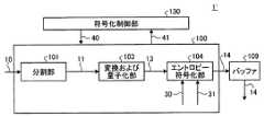
以下、第1の実施形態を図面を参照しながら説明する。図1Aは、本発明の第1の実施形態に適用可能な画像符号化装置1の一例の構成を示すブロック図である。この画像符号化装置1は、画像符号化部100、符号化制御部130およびバッファ109を有する。<First Embodiment>
Hereinafter, a first embodiment will be described with reference to the drawings. FIG. 1A is a block diagram showing a configuration of an example of an
画像符号化部100に対して、動画像データが所定サイズに分割された画像ブロック10が入力される。画像符号化部100は、符号化制御部130の制御に従い、入力された画像ブロック10を所定サイズの小画素ブロック11に分割する。画像符号化部100は、この小画素ブロック11に基づき、変換処理および量子化処理、予測符号化処理、ならびに、エントロピー符号化処理を行い、符号化データ14を生成する。 An
符号化データ14は、バッファ109に一旦溜め込まれ、例えば1フレームを単位として画像符号化装置1から出力される。なお、この画像符号化部100における各処理は、動画像データの各画像信号成分(例えば輝度成分Y、色差成分U、V)に対してそれぞれ行われる。 The encoded
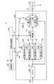
画像符号化部100の一例の構成について、より詳細に説明する。図1において、画像符号化部100は、分割部101、減算器102、変換および量子化部103、エントロピー符号化部104、逆量子化および逆変換部105、加算器106、メモリ107、予測部108を有し、符号化制御部130によって制御される。 The configuration of an example of the
符号化制御部130は、画像符号化装置1による符号化処理全般を制御するための符号化制御情報40を、画像符号化部100に供給する。また、符号化制御部130は、画像符号化部100における符号化処理の結果に基づき出力されるフィードバック情報41を、適宜、受け取る。符号化制御情報40は、モード情報31および符号化方法情報30などを含む。モード情報31は、後述する予測モードを示す予測モード情報や、量子化パラメータ(QP)、量子化幅(量子化ステップサイズ)、量子化マトリクスなどの量子化処理に関するパラメータを含む量子化情報といった、変換係数以外の復号に必要な情報を含む。フィードバック情報41は、画像符号化部100での発生符号量を示す符号量情報が含まれる。 The
画像符号化部100は、例えばLSI(Large−Scale Integration)チップ上に構成された回路などのハードウェアにより実現される。この場合、符号化制御部130は、当該LSIに接続されるCPU(Central Processing Unit)上でプログラムを実行させることで実現してもよいし、画像符号化部100と同様にしてハードウェアで構成してもよい。画像符号化部100は、符号化制御部130と共に、コンピュータなどでCPU上で画像符号化プログラムを実行させることでも実現可能である。 The
入力された画像ブロック10は、分割部101において所定サイズのブロック単位に分割され、小画素ブロック11とされる。ここで、画像ブロック10は、1フレームの画像データまたは1フレームの画像データを分割した一領域である。例えば、画像ブロック10は、n画素×m画素(n,mはそれぞれ自然数)からなる画素ブロックであって、1ライン分の画素データからなる画素ラインや、複数ライン分の画素データからなる画素ブロックラインも画像ブロックの概念に含まれる。小画素ブロック11は、例えばN画素×M画素からなる画素ブロック(N,Mはそれぞれ自然数、且つ、N≦nおよびM≦m)である。画像符号化部100では、この小画素ブロック11を単位として予測符号化処理や変換処理などが行われる。 The
分割部101から出力された小画素ブロック11は、減算器102に供給される。減算器102は、供給された小画素ブロック11から、後述する予測部108より出力される予測画像信号19を減算して、予測誤差信号12を生成する。予測誤差信号12は、変換および量子化部103に供給される。 The
変換および量子化部103は、先ず、供給された予測誤差信号12に対して所定の変換処理を施し、変換係数を生成する。ここでは、変換処理として、アダマール変換やDCT(離散コサイン変換)といった直交変換を用いる。これに限らず、ウェーブレット変換や独立成分解析などの手法を用いて変換係数を生成してもよい。 First, the transform and quantization unit 103 performs a predetermined transform process on the supplied
直交変換の例について、図2A、図2Bおよび図2Cを用いて説明する。図2Aは4×1変換、図2Bは2×2変換、図2Cは4×4変換の例をそれぞれ示す。 An example of orthogonal transform will be described with reference to FIGS. 2A, 2B, and 2C. 2A shows an example of 4 × 1 conversion, FIG. 2B shows an example of 2 × 2 conversion, and FIG. 2C shows an example of 4 × 4 conversion.
4×1変換では、図2Aに例示されるように、分割部101で4画素×1画素の小画素ブロック11を生成し、4画素×1画素でブロック化された予測誤差信号12に対して、水平1次元の直交変換を適用する。直交変換後の変換係数は、空間周波数成分に分解されている。図2Aの例では、値「0」で示される位置が最も空間周波数が低いDC成分を表し、値が大きくなる位置ほど高い空間周波数成分を表す。 In the 4 × 1 conversion, as illustrated in FIG. 2A, the dividing
2×2変換では、図2Bに例示されるように、分割部101で2画素×2画素の小画素ブロック11を生成し、2画素×2画素でブロック化された予測誤差信号12に対して、水平および垂直方向の2次元の直交変換を適用する。図中の値(x,y)は、値xが垂直方向の空間周波数成分の位置、値yが水平方向の空間周波数成分の位置を示し、それぞれ数値が大きいほど高い空間周波数成分を表す。図2Bの例では、左上の値(0,0)で示される位置が最も空間周波数が低いDC成分を表し、右下の値(1,1)で示される位置が最も高い空間周波数成分を表す。 In the 2 × 2 conversion, as illustrated in FIG. 2B, the
なお、以下では、2×2変換において位置を示す値「0」をLowを意味する「L」とし、値「1」をHighを示す「H」として、垂直方向、水平方向の順に各成分を表す。例えば、値(0,0)のDC成分は、LL成分と表記し、各AC成分をそれぞれHL成分、LH成分、HH成分として、適宜、各成分を表記する。 In the following description, the value “0” indicating the position in the 2 × 2 conversion is set to “L” meaning Low, the value “1” is set to “H” indicating High, and the respective components are sequentially arranged in the vertical direction and the horizontal direction. Represent. For example, a DC component having a value (0, 0) is expressed as an LL component, and each AC component is appropriately described as an HL component, an LH component, and an HH component.
4×4変換では、図2Cに例示されるように、分割部101で4画素×4画素の小画素ブロック11を生成し、4画素×4画素でブロック化された予測誤差信号12に対して、水平および垂直方向の2次元の直交変換を適用する。図2Cの例では、値(x,y)は、値xおよび値yは、それぞれ垂直方向および水平方向の空間周波数成分の位置を示し、それぞれ数値が大きいほど高い空間周波数成分を表す。値(0,0)がDC成分位置を示し、値(3,3)が最も空間周波数成分が高い位置となる。 In the 4 × 4 conversion, as illustrated in FIG. 2C, the dividing
変換および量子化部103では、上述のようにして生成された変換係数を、後述する符号化制御部130に設定されている量子化パラメータQPに基づき量子化し、量子化された変換係数である量子化変換係数13を生成する。量子化変換係数13は、エントロピー符号化部104に供給されると共に、逆量子化および逆変換部105に供給される。 The transform and quantization unit 103 quantizes the transform coefficient generated as described above based on a quantization parameter QP set in the
逆量子化および逆変換部105は、量子化変換係数13を符号化制御部130に設定されている量子化パラメータQPに従って逆量子化して量子化変換係数13を復元する。そして、復元された量子化変換係数13に対して変換および量子化部103で行った変換と逆の変換を行い、元の予測誤差信号12を復元した復元予測誤差信号16を生成する。復元予測誤差信号16は、加算器106に供給される。加算器106は、この復元予測誤差信号16と、予測部108から出力される予測画像信号19とを加算して、元の小画素ブロック11が復元された復元小画素ブロック信号17を生成する。 The inverse quantization and inverse transform unit 105 dequantizes the quantized
復元小画素ブロック信号17は、メモリ107に記憶され、参照画素信号18として予測部108に供給され、後に符号化処理される小画素ブロック11の予測に用いられる。 The restored small
予測部108は、分割部101から出力された小画素ブロック11に対して、イントラ予測を適用する。図3A〜図3Eは、イントラ予測の具体的な例を示す。図3A〜図3Eは、それぞれ予測方向の異なる5種類の予測モードが示されている。すなわち、イントラ予測においては、メモリ107に記憶される参照画素信号18のうち、予測対象の画素ブロック(この例では、2画素×2画素からなる画素ブロック)に対して空間的に近接する画素信号を用いて、当該画素ブロックの画素値を予測する。 The
より具体的には、画像においては隣接画素同士の相関が高いことを利用して、予測方向に従って参照画素信号18の輝度値を予測対象の画素ブロックに対してコピーすることで、予測画像信号19を生成する。図3A〜図3Eにおいて、文字「a」〜「d」が記された升が予測対象となる画素(以下、予測対象画素)であり、影を付して示される、文字「A」〜「G」が記された升が参照画素信号18による画素(以下、参照画素)を示す。 More specifically, by utilizing the fact that the correlation between adjacent pixels is high in the image, the predicted
図3Aは水平方向に予測を行う例である。具体的には、参照画素「E」を水平方向に近接して並ぶ予測対象画素「a」および「b」にコピーし、参照画素「F」を水平方向に近接して並ぶ予測対象画素「c」および「d」にコピーする。図3Bは垂直方向に予測を行う例である。具体的には、参照画素「A」を垂直方向に近接して並ぶ予測対象画素「a」および「c」にコピーし、参照画素「B」を垂直方向に近接して並ぶ予測対象画素「b」および「d」にコピーする。 FIG. 3A is an example in which prediction is performed in the horizontal direction. Specifically, the reference pixel “E” is copied to the prediction target pixels “a” and “b” arranged close to each other in the horizontal direction, and the reference pixel “F” is arranged close to the horizontal direction. ”And“ d ”. FIG. 3B is an example in which prediction is performed in the vertical direction. Specifically, the reference pixel “A” is copied to the prediction target pixels “a” and “c” arranged close to each other in the vertical direction, and the reference pixel “B” is arranged adjacent to each other in the vertical direction. ”And“ d ”.
また、図3Cは左上および右下を結ぶ斜め方向に予測を行う例である。具体的には、参照画素「E」を右斜め下の予測対象画素「c」にコピーし、参照画素「G」を右斜め下の予測対象画素「a」および「d」にコピーする。そして、参照画素「A」を右斜め下の予測対象画素「b」にコピーする。図3Dは右上および左下を結ぶ斜め方向に予測を行う例である。具体的には、参照画素「B」を左斜め下の予測対象画素「a」にコピーし、参照画素「C」を左斜め下の予測対象画素「b」および「c」にコピーする。そして、参照画素「D」を左斜め下の予測対象画素「d」にコピーする。 FIG. 3C is an example in which prediction is performed in an oblique direction connecting the upper left and the lower right. Specifically, the reference pixel “E” is copied to the lower right prediction target pixel “c”, and the reference pixel “G” is copied to the lower right prediction target pixels “a” and “d”. Then, the reference pixel “A” is copied to the prediction target pixel “b” on the lower right. FIG. 3D is an example in which prediction is performed in an oblique direction connecting the upper right and the lower left. Specifically, the reference pixel “B” is copied to the lower left prediction target pixel “a”, and the reference pixel “C” is copied to the lower left prediction target pixels “b” and “c”. Then, the reference pixel “D” is copied to the prediction target pixel “d” on the lower left.
さらに、図3Eは、予測対象となる画素ブロックに隣接する参照画素の平均値を用いて予測を行う例である。具体的には、参照画素「A」、「B」、「E」および「F」の輝度値の平均値を求めて、予測対象画素「a」〜「d」にそれぞれコピーする。 Furthermore, FIG. 3E is an example in which prediction is performed using an average value of reference pixels adjacent to a pixel block to be predicted. Specifically, the average value of the luminance values of the reference pixels “A”, “B”, “E”, and “F” is obtained and copied to the prediction target pixels “a” to “d”, respectively.
このようにして予測部108で予測された予測画像信号19が上述した減算器102に供給される。 The predicted
なお、予測部108における予測方法は、上述の例に限定されない。例えば、平面予測やJPEG−LS(Joint Photographic Experts Group−LS)に採用されているMED(Median Edge Detection)予測、CALIC(Context−based Adaptive Lossless Image Coding)方式に用いられている傾斜適応予測を用いてもよい。また、ピクチャの境界など、予測対象の画素ブロックに隣接する参照画素が存在しない場合には、予測値を「0」として予測無しとしたり、予測値として例えば値「128」などの固定値を用いて予測画像信号19としてもよい。さらに、予測部108に対して、H.264/AVCに採用されているインター予測を適用してもよい。また、図1Bに画像符号化装置1’として例示するように、上述した画像符号化装置1から予測部108を取り除いた構成としてもよい。この場合、予測は行われず、画像ブロック10が直接的に変換および量子化部103に入力される。予測部108を取り除いた場合、予測に関する他の構成、すなわち、減算器102、逆量子化および逆変換部105、加算器106、ならびに、メモリ107が不要となる。 Note that the prediction method in the
一方、エントロピー符号化部104は、符号化制御部130などから取得した符号化パラメータに基づき、変換および量子化部103から供給された量子化変換係数13をエントロピー符号化し、符号化データ14として出力する。エントロピー符号化方式としては、等長符号化、ハフマン符号化、算術符号化などの方式を用いることができる。 On the other hand, the
また、エントロピー符号化部104が用いる符号化パラメータは、符号化制御情報40に含まれる符号化方法情報30、予測モード情報や量子化パラメータ情報などによるモード情報31を含む。当該符号化パラメータは、変換および量子化部103における変換係数や量子化に関する情報といった、復号の際に必要となる様々なパラメータを含む。 Also, the encoding parameters used by the
エントロピー符号化部104により生成された符号化データ14は、画像符号化部100から出力され、図示されない多重化処理を経てバッファ109に一旦溜め込まれる。バッファ109に溜め込まれた符号化データ14は、符号化制御部130が管理する出力タイミングに従って、例えば画像符号化装置1の外部に向けて符号化データ14として出力される。画像符号化装置1から出力された符号化データ14は、例えば、ハードディスクや半導体メモリといった記憶媒体に記憶されたり、通信回線などの伝送系により伝送される。 The encoded
次に、画像符号化装置1におけるエントロピー符号化部104について、より詳細に説明する。図4は、本第1の実施形態に適用可能なエントロピー符号化部104の一例の構成を示すブロック図である。図4において、エントロピー符号化部104は、係数符号化部110、符号化方法符号化部111およびモード符号化部112を有する。 Next, the
変換および量子化部103から出力された量子化変換係数13が係数符号化部110に入力される。また、符号化方法情報30が係数符号化部110および符号化方法符号化部111にそれぞれ供給される。また、モード情報31がモード符号化部112に供給される。 The quantized
符号化方法情報30は、係数符号化部110における量子化変換係数13の符号化方法を指定するための情報である。より具体的には、符号化方法情報30は、画像の所定単位、例えば小画素ブロック単位、入力画像信号単位、フレーム単位またはシーケンス単位で、後述する係数位置毎の可変長符号化方法を示す。また、モード情報31は、復号時に必要となる変換係数以外の情報からなる。例えば、モード情報31には、変換および量子化部103において量子化の際に用いた量子化パラメータQPを示す量子化パラメータ情報や、直交変換後の変換係数の位置を示す位置情報が含まれる。 The
なお、変換係数の位置とは、空間周波数の成分の方向を座標軸とし、空間周波数を座標値として考えた場合の、直交変換により得られた変換係数の位置であるものとする。すなわち、係数位置は、直交変換における空間周波数成分に対応する。一例として、上述した図2Bの例では、水平方向および垂直方向による各座標軸が、それぞれ低周波成分(L)と高周波成分(H)とに2分割されて、各変換係数の位置が表される。すなわち、図2Bの例では、変換係数の位置は、座標(L,L)、座標(H,L)、座標(L,H)または座標(H,H)として表されることになる。 Note that the position of the transform coefficient is the position of the transform coefficient obtained by orthogonal transform when the direction of the spatial frequency component is taken as the coordinate axis and the spatial frequency is considered as the coordinate value. That is, the coefficient position corresponds to the spatial frequency component in the orthogonal transformation. As an example, in the example of FIG. 2B described above, each coordinate axis in the horizontal direction and the vertical direction is divided into two, a low-frequency component (L) and a high-frequency component (H), and the position of each conversion coefficient is represented. . That is, in the example of FIG. 2B, the position of the conversion coefficient is expressed as coordinates (L, L), coordinates (H, L), coordinates (L, H), or coordinates (H, H).
以下では、2×2変換の場合における座標(L,L)、座標(H,L)、座標(L,H)または座標(H,H)の各変換係数の係数位置を、それぞれ位置LL、位置HL、位置LHおよび位置HHのように表記する。 In the following, the coefficient position of each conversion coefficient of coordinates (L, L), coordinates (H, L), coordinates (L, H), or coordinates (H, H) in the case of 2 × 2 conversion will be represented as position LL, It describes as position HL, position LH, and position HH.
これら符号化方法情報30およびモード情報31は、それぞれ画像符号化部100の外部から供給される。例えば、符号化方法情報30およびモード情報31は、それぞれ符号化制御部130で生成されて符号化制御情報40に含めて画像符号化部100に供給され、エントロピー符号化部104に入力される。 The
係数符号化部110は、量子化変換係数13のエントロピー符号化を、符号化方法情報30に従い、係数位置毎の符号化方法を画像の所定単位、例えば画像ブロック10単位で切り替えながら行う。一方、符号化方法符号化部111が符号化方法情報30を符号化すると共に、モード符号化部112がモード情報31を符号化する。符号化方法符号化部111の符号化出力と、モード符号化部112の符号化出力とが、係数符号化部110による符号化出力に対して埋め込まれて、符号化データ14とされ、エントロピー符号化部104から出力される。 The
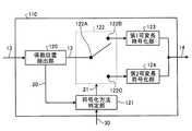
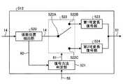
次に、上述したエントロピー符号化部104における係数符号化部110について、より詳細に説明する。図5は、本第1の実施形態による係数符号化部110の一例の構成を示すブロック図である。係数符号化部110は、係数位置抽出部120、符号化方法判定部121、スイッチ部122、ならびに、第1可変長符号化部123および第2可変長符号化部124を有する。 Next, the
量子化変換係数13が係数符号化部110に入力され、係数位置抽出部120に供給される。係数位置抽出部120は、供給された量子化変換係数13をスイッチ部122の入力端122Aに供給すると共に、当該量子化変換係数13から係数位置を抽出し、当該係数位置を示す係数位置情報20を出力する。例えば、量子化変換係数13を小画素ブロック11毎に計数することで、当該小画素ブロック11における量子化変換係数13の係数位置を知ることができる。 The quantized
スイッチ部122は、後述する符号化方法判定部121から出力される切替信号21により、出力端122Bおよび122Cが切り替えられる。出力端122Bおよび122Cに対して、第1可変長符号化部123および第2可変長符号化部124がそれぞれ接続される。すなわち、入力端122Aに供給された量子化変換係数13は、切替信号21に応じて第1可変長符号化部123および第2可変長符号化部124の何れか一方に、選択的に供給される。 In the
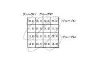
係数位置情報20は、係数位置単位で情報を示してもよいし、係数位置に応じてグループ分けしたグループ単位で情報を示してもよい。図6Aおよび図6Bは、係数位置のグループ分けの例を示す。図6Aおよび図6Bの例では、水平および垂直成分を統合した係数位置すなわち空間周波数に応じてグループ分けを行っている。 The
図6Aは、2×2変換において、係数位置を3グループに分けている例である。図6Aの例では、水平および垂直成分が何れも低周波数成分(L)であるグループ#1と、水平および垂直成分のうち一方が低周波数成分であるグループ#2と、水平および垂直成分が何れも高周波成分(H)であるグループ#3とにグループ分けされている。 FIG. 6A is an example in which coefficient positions are divided into three groups in 2 × 2 conversion. In the example of FIG. 6A,
図6Bは、4×4変換において、係数位置を4グループに分けている例である。図6Bの例では、空間周波数を0〜3の4段階に分類したときに、水平および垂直成分の合計値がそれぞれ0であるグループ#1と、当該合計値が1または2であるグループ#2と、当該合計値が3または4であるグループ#3と、当該合計値が5以上のグループ#4との4グループにグループ分けされている。 FIG. 6B is an example in which the coefficient positions are divided into four groups in the 4 × 4 conversion. In the example of FIG. 6B, when the spatial frequency is classified into four stages of 0 to 3,
係数位置情報20は、符号化方法判定部121に供給される。符号化方法判定部121には、符号化方法情報30も供給される。符号化方法判定部121は、係数位置情報20と符号化方法情報30とに基づき、係数位置単位または位置グループ単位に切替信号21を出力し、スイッチ部122に供給する。これにより、スイッチ部122が符号化方法情報30に基づき係数位置または位置グループ単位に切り替えられる。係数位置単位または位置グループ単位で適応的に、第1可変長符号化部123または第2可変長符号化部124に対して、量子化変換係数13が供給される。 The
ここで、第1可変長符号化部123でなされる第1の可変長符号化と、第2可変長符号化部124でなされる第2の可変長符号化について説明する。第1可変長符号化部123では、第1の可変長符号化として、量子化変換係数13に対して1シンボルずつ符号を割り当てる、1シンボル単位符号化を適用する。このような1シンボル単位符号化の典型的な例としては、ゴロム・ライス符号化、ハフマン符号化および固定長符号化が知られている。 Here, the first variable length coding performed by the first variable
図7は、ゴロム・ライス符号の例を示す。ゴロム・ライス符号は、可変長のunary符号の列prefixと、固定長の符号列suffixとを連結した符号である。図7において、符号列suffixの符号長kの値に応じた予測残差を符号化した際の符号化列が示されている。ゴロム・ライス符号を復号する際には、どの符号長kの値を用いて符号化したかという情報が必要となる。そのため、符号長kの値を、ゴロム・ライス符号の符号化パラメータとして、復号側に渡す。 FIG. 7 shows an example of Golomb-Rice code. The Golomb-Rice code is a code obtained by concatenating a variable-length unary code string prefix and a fixed-length code string suffix. FIG. 7 shows an encoded sequence when encoding a prediction residual according to the value of the code length k of the code sequence suffix. When decoding the Golomb-Rice code, information on which code length k is used for encoding is necessary. Therefore, the value of the code length k is passed to the decoding side as the encoding parameter of the Golomb-Rice code.
なお、第1の可変長符号化としてハフマン符号化を用いる場合、予め与えられたハフマン符号化の符号表を決定する確率モデルを示す情報を、符号化パラメータkとして復号側に渡す。 When Huffman coding is used as the first variable length coding, information indicating a probability model for determining a code table of Huffman coding given in advance is passed to the decoding side as a coding parameter k.
第2可変長符号化部124では、第2の可変長符号化として、供給された、量子化変換係数13に対して、同一の係数位置の複数シンボルに対して纏めて符号を割り当てることが可能な複数シンボル一括符号化を適用する。このような複数シンボル一括符号化の典型的な例として、ランレングス符号およびスキップ符号化が知られている。 In the second variable
ランレングス符号化について、概略的に説明する。ランレングス符号化は、一連のシンボル群を、そのデータの値(value)と連続数(ラン数run)とで表現するようにした符号化方式である。ランレングス符号化は、同一のシンボルが連続している場合に、この連続したシンボルを纏めて符号化することが可能であるため、平坦な画像などにおいて高い符号化効率が期待できる。ランレングス符号化では、シンボルが、保持された状態(state)と等しい場合にラン数をカウント(インクリメント)し、保持された状態state以外のシンボルでは、そのシンボルの値(value)を符号化する。この、保持された状態state以外のシンボルを符号化する符号化方式としては、ゴロム・ライス符号化や固定長符号化などを用いることができる。また、ラン数runは、画像ブロック10内の小画素ブロック11の数に応じて、ゴロム・ライス符号化若しくはハフマン符号化あるいは固定長符号化を用いて符号化する。 Run-length encoding will be schematically described. Run-length coding is a coding method in which a series of symbol groups is expressed by a value (value) of the data and a continuous number (run number run). In the run-length encoding, when the same symbols are continuous, it is possible to encode the continuous symbols collectively, and therefore high encoding efficiency can be expected in a flat image or the like. In run-length encoding, the number of runs is counted (incremented) when a symbol is equal to a held state (state), and the symbol value (value) is encoded for a symbol other than the held state. . As a coding method for coding symbols other than the held state state, Golomb-Rice coding, fixed-length coding, or the like can be used. The run number run is encoded using Golomb-Rice encoding, Huffman encoding, or fixed-length encoding according to the number of small pixel blocks 11 in the
図8は、ランレングス符号化の一例の処理手順を示すフローチャートである。この図8に例示されるフローチャートにおける各処理は、第2可変長符号化部124において実行される。先ず、ラン数runと、データの状態を表す状態stateとにそれぞれ0を代入して初期化する(ステップS301)。次に、ステップS303で、符号化対象のシンボルxが状態stateと等しいか否かを判定する。若し、シンボルxが状態stateと等しいと判定された場合(ステップS303の「YES」)、処理はステップS304に移行され、ラン数runの値を1だけインクリメントする。そして、処理がステップS307に移行される。 FIG. 8 is a flowchart illustrating an example of a process procedure of run-length encoding. Each process in the flowchart illustrated in FIG. 8 is executed by the second variable
一方、ステップS303で、符号化対象のシンボルxが状態stateと等しくないと判定された場合は(ステップS303の「NO」)、処理はステップS305に移行される。ステップS305では、ラン数runおよびシンボルxを符号化する。その後、ラン数runに0を代入すると共に状態stateをシンボルxで更新し(ステップS306)、処理がステップS307に移行される。 On the other hand, if it is determined in step S303 that the encoding target symbol x is not equal to the state state (“NO” in step S303), the process proceeds to step S305. In step S305, the run number run and the symbol x are encoded. Thereafter, 0 is substituted for the run number run and the state state is updated with the symbol x (step S306), and the process proceeds to step S307.
ステップS307では、全ての符号化対象のシンボルに対して、ステップS303〜ステップS306の処理を実行したか否かが判定される。若し、全ての符号化対象シンボルに対して処理が実行されていないと判定されたら、ステップS302で符号化対象を次のシンボルに移動させて、処理がステップS303に戻される。 In step S307, it is determined whether or not the processing in steps S303 to S306 has been executed for all symbols to be encoded. If it is determined that the processing has not been executed for all the encoding target symbols, the encoding target is moved to the next symbol in step S302, and the processing returns to step S303.
一方、ステップS307で全ての符号化対象シンボルに対して処理が実行されたと判定されたら、処理はステップS308に移行される。ステップS308では、ラン数runが0より大きければ、ラン数runを符号化する。すなわち、上述のステップS304からステップS307を介してステップS308に移行された場合に、ラン数runの符号化を行う。この場合、符号化対象のシンボル総数MAX_NUMが既知の場合、ラン数runの値を1デクリメントした値を符号化してもよい。なお、ステップS308でラン数runが0であれば、そのまま一連の処理が終了される。 On the other hand, if it is determined in step S307 that the process has been executed for all the encoding target symbols, the process proceeds to step S308. In step S308, if the run number run is greater than 0, the run number run is encoded. That is, when the process proceeds from step S304 to step S308 via step S307, the run number run is encoded. In this case, when the total number of symbols to be encoded MAX_NUM is known, a value obtained by decrementing the value of the run number run by 1 may be encoded. If the run number run is 0 in step S308, the series of processing ends.
図9は、符号化対象シンボル総数MAX_NUM=16の場合のシンボル位置(num)毎のランレングス符号化の具体的な処理の例を示す。図9の例では、シンボル位置num=0〜4において、値が0の符号化対象シンボルが連続している。そのため、これらのシンボルの処理時には、ステップS303の判定により処理がステップS304に移行されて、ラン数runが1ずつインクリメントされる。状態stateは更新されず、値0が維持される。 FIG. 9 shows an example of specific processing for run-length encoding for each symbol position (num) when the total number of encoding target symbols MAX_NUM = 16. In the example of FIG. 9, the encoding target symbols having a value of 0 are continuous at the symbol positions num = 0-4. Therefore, when processing these symbols, the process proceeds to step S304 according to the determination in step S303, and the run number run is incremented by one. The state state is not updated and the
また、図9の例では、シンボル位置num=5で符号化対象のシンボルの値が1となっている。この値は状態stateの値と異なるため、ステップS303の判定により処理がステップS305に移行され、ラン数runとシンボル位置num=5におけるシンボルの値1が符号化される。そして、ラン数runに0が代入されると共に状態stateの値が当該シンボルの値1に更新される。 In the example of FIG. 9, the value of the symbol to be encoded is 1 at the symbol position num = 5. Since this value is different from the value of the state state, the process proceeds to step S305 according to the determination in step S303, and the
このように、ランレングス符号化においては、符号化対象のシンボル値において同一値が連続して現れる場合には、ラン数runを1ずつインクリメントする。異なるシンボル値が現れた場合に、ラン数runおよび当該異なるシンボル値を符号化する。図9の例では、シンボル位置num=8〜11においてシンボル位置毎に異なるシンボル値が現れているので、ラン数runおよびシンボル値の符号化が毎回行われている。 In this way, in run-length encoding, the run number run is incremented by 1 when the same value appears continuously in the symbol value to be encoded. When different symbol values appear, the run number run and the different symbol values are encoded. In the example of FIG. 9, since different symbol values appear for each symbol position at the symbol positions num = 8 to 11, the run number run and the encoding of the symbol values are performed each time.
なお、上述した図8のフローチャートによる処理において、値が0となるシンボルの出現頻度が高い場合には、状態stateの値を0に固定的としてもよい。これにより、シンボル値が0の場合にラン数runを符号化する必要がなくなるため、符号化効率を向上できる。 In the process according to the flowchart of FIG. 8 described above, the value of the state state may be fixed to 0 when the appearance frequency of the symbol having a value of 0 is high. This eliminates the need to encode the run number run when the symbol value is 0, thereby improving the encoding efficiency.
次に、上述したスキップ符号化について、概略的に説明する。スキップ符号化は、一連のシンボル群を複数のグループに分割し、グループ内のシンボルが全てゼロであるか否かを判定し、この判定結果に基づいて符号化を行う符号化方式である。 Next, the skip encoding described above will be schematically described. Skip coding is a coding method in which a series of symbol groups are divided into a plurality of groups, whether or not all symbols in the group are zero, and coding is performed based on the determination result.
スキップ符号化の具体的な例を、図10に示す。図10の例では、シンボル位置を4つのグループに分け、それぞれのグループ内でシンボルが全て0であるか否かを判定する。グループ内のシンボルが全て0である場合、スキップ情報を示すフラグskipflag=TRUEであることを示す情報を符号化する。すなわち、グループ内のシンボルが全て0である場合には、フラグskipflag=TRUEを示す情報のみを符号化するだけで、そのグループ内のシンボルが符号化される。一方、グループ内のシンボルの少なくとも1つが0ではない場合、フラグskipflag=FALSEであることを示す情報を符号化し、さらにグループ内の個々のシンボルをゴロム・ライス符号、ランレングス符号などの可変長符号などを使用して符号化する。 A specific example of skip encoding is shown in FIG. In the example of FIG. 10, the symbol positions are divided into four groups, and it is determined whether or not all symbols are 0 in each group. When all symbols in the group are 0, information indicating that the flag skipflag = TRUE indicating skip information is encoded. That is, when all the symbols in the group are 0, only the information indicating the flag skipflag = TRUE is encoded, and the symbols in the group are encoded. On the other hand, if at least one of the symbols in the group is not 0, information indicating that the flag skipflag = FALSE is encoded, and further, individual symbols in the group are variable length codes such as Golomb-Rice code and run-length code. And so on.
上述したように、第1可変長符号化部123による符号化では、1シンボル当たり1ビット未満の符号割り当てが不可能である。これに対して、第2可変長符号化部124による符号化では、同一のシンボル(特に0)が連続するようなシンボル列を纏めて符号化し、1シンボル当たり1ビット未満の符号割り当てが可能となる。そのため、第2可変長符号化部124では、画像の平坦領域や、予測が有効な領域において、符号化効率を向上させることが可能となる。 As described above, the encoding by the first variable
一方、第2可変長符号化部124による符号化は、例えば上述した図9のシンボル位置num=8〜11に示すように同一のシンボルが連続しない場合には、シンボル毎にラン数runを符号化する必要がある。そのため、シンボル列において同一のシンボルが連続しないテクスチャ領域や、予測が有効でない領域においては、第2可変長符号化部124による符号化は、第1可変長符号化部123による符号化と比較して符号化性能が悪化する。すなわち、このような同一のシンボルが連続しないような領域では、第1可変長符号化部123による符号化が有効となる。 On the other hand, the encoding by the second variable
次に、本実施形態による画像符号化装置1において特徴的な処理である、エントロピー符号化部104内の係数符号化部110の処理について、より詳細に説明する。なお、以下では、画像符号化装置1に入力される画像ブロック10は、2ラインからなるブロックであるものとする(図11A参照)。この画像ブロック10が分割部101で、2画素×2画素のサイズを持つ小画素ブロック11、11、…に分割されるものとする(図11B参照)。画像ブロック10は、符号化対象フレーム中の符号化処理の対象領域である。画像ブロック10内に存在する少画像ブロック11のそれぞれは、符号化処理の対象ブロックである。 Next, the processing of the
なお、小画素ブロック11のサイズは、係数符号化部110において直交変換を適用するサイズと対応するものとする。小画素ブロック11のサイズが2画素×2画素であるこの例では、直交変換は、図2Bを用いて説明した2×2変換により行われる。 Note that the size of the
小画素ブロック11を生成するための他の方法として、画像ブロック10のサイズを例えば8画素×8画素(図12A参照)、小画素ブロック11のサイズを例えば2画素×2画素とする。そして、図12Bに例示されるように、小画像ブロック11のサイズで画像ブロック10の内部をジグザグスキャンすることで、画像ブロック10の画素データを小画素ブロック11のサイズに従い並べ替えてもよい。 As another method for generating the
図13は、上述した2ラインの画素データによる画像ブロック10と、当該画像ブロック10が2画素×2画素のブロックに分割された小画素ブロック11、11、…とを、係数位置LL、HL、LHおよびHHを用いて表現した例を示す。なお、図13中の数字0、1、…は、小画素ブロック11を区別するために便宜的に付した番号である。値BLKは、画像ブロック10内の小画素ブロック11の数を示す。また、以下では、係数位置LL、HL、LHおよびHHを、適宜、係数位置[pos]として記述する。この場合、値posは、値LL、HL、LHおよびHHの何れかとなる。 FIG. 13 shows coefficient blocks LL, HL, an
すなわち、2画素×2画素からなる小画素ブロック11に対して2×2変換を施すと、水平および垂直成分がそれぞれ低周波成分からなる、位置LLに対応する量子化変換係数13と、水平および垂直成分の何れか一方が低周波成分からなる、位置HLおよび位置LHにそれぞれ対応する量子化変換係数13と、水平および垂直成分がそれぞれ高周波成分からなる、位置HHに対応する量子化変換係数13とがそれぞれ生成される。 That is, when 2 × 2 conversion is performed on the
なお、変換係数を水平および垂直方向の係数位置、ならびに、小画素ブロック11の画像ブロック10上での位置に応じて並べてなる面を、係数面と呼ぶ。 A surface in which the transform coefficients are arranged in accordance with the horizontal and vertical coefficient positions and the position of the
図14A〜図14Dは、図13に例示した係数面上の各量子化変換係数13、13、…を、係数位置毎に、画像ブロック10単位でそれぞれ纏めて並べ替えた例を示す。ここでは、2画素×2画素のサイズの小画素ブロック11に対して2×2変換を適用するため、各小画素ブロック11、11、…は、それぞれ4の係数位置LL、HL、LHおよびHHで表現される。図14Aは、係数面における位置LLの係数を纏めた例である。図14Bは、係数面における位置HLの係数を纏めた例である。図14Cは、係数面における位置LHの係数を纏めた例である。図14Dは、係数面における位置HHの係数を纏めた例である。すなわち、図14A〜図14Dのそれぞれは、変換係数を周波数成分毎に並べた係数列を示す。なお、図14A〜図14Dにおいて、同じ番号の係数は、同一の小画素ブロック11に属することを示す。 14A to 14D show examples in which the quantized
本実施形態においては、係数位置LL、HL、LHおよびHH、すなわち、変換係数を周波数成分毎に並べた係数列に対して、第1可変長符号化部123による第1の可変長符号化と、第2可変長符号化部124による第2の可変長符号化とがそれぞれ選択的に適用される。本実施形態の第1の可変長符号化は、係数列を係数毎に可変長符号化する方式である。本実施形態の第2の可変長符号化は、係数列内で1ビット以上の可変長の部分データ毎に符号化する方式である。係数位置LL、HL、LHおよびHHすなわち係数位置[pos]に対して、それぞれ第1可変長符号化および第2可変長符号化のうち何れを適用させるかは、フラグCodingMethodFlag[pos]により示す。値posは、係数位置LL、HL、LHおよびHHをそれぞれ示す値LL、HL、LHおよびHHである。このフラグCodingMethodFlag[pos]は、上述した符号化方法情報30に相当する。 In the present embodiment, the first variable
より具体的な例として、フラグCodingMethodFlag[pos]が値TRUEを示す場合、値[pos]で示される周波数成分の量子化変換係数13に対して、第1の可変長符号化を適用する。一方、フラグCodingMethodFlag[pos]が値FALSEを示す場合、値[pos]で示される周波数成分の量子化変換係数13に対して、第2の可変長符号化を適用する。なお、第1の可変長符号化および第2の可変長符号化の何れかを示すフラグCodingMethodFlag[pos]の値は、上述のTRUEおよびFALSEに限られず、例えば0および1を用いてもよい。 As a more specific example, when the flag CodingMethodFlag [pos] indicates the value TRUE, the first variable length coding is applied to the quantized
すなわち、上述した図5に例示される構成において、符号化方法判定部121は、係数位置抽出部120から供給された係数位置情報20と、符号化制御部130などから供給された符号化方法情報30とに基づき、スイッチ部122を制御する。より具体的には、係数位置情報20が示す係数位置[pos]に対応するフラグCodingMethodFlag[pos]が値TRUEを示していれば、出力端122Bを選択するように、スイッチ部122を制御する。一方、係数位置[pos]に対応するフラグCodingMethodFlag[pos]が値FALSEを示していれば、出力端122Cを選択するように、スイッチ部122を制御する。 That is, in the configuration illustrated in FIG. 5 described above, the encoding
第1の可変長符号化にゴロム・ライス符号化を、第2の可変長符号化にランレングス符号化を適用した場合には、上述したゴロム・ライス符号化による符号化パラメータkを画素ブロック10毎に最適化する。符号化パラメータkが最適化された最適化符号化パラメータbest_kは、量子化変換係数13が符号化された符号化データと共に、復号側に伝送される。 When Golomb-Rice encoding is applied to the first variable-length encoding and run-length encoding is applied to the second variable-length encoding, the encoding parameter k by the Golomb-Rice encoding described above is set to the
図15は、係数符号化部110における一例の処理を示すフローチャートである。この図15に例示する処理は、第1の可変長符号化としてゴロム・ライス符号化を用い、ゴロム・ライス符号化における符号化長である符号化パラメータkが予め決められている場合の例である。第2の可変長符号化としては、ランレングス符号化を用いるものとする。 FIG. 15 is a flowchart illustrating an example of processing in the
なお、以下では、小画素ブロック11が2画素×2画素からなるものとする。また、符号化パラメータkは、例えばエントロピー符号化部104において固定的に決められているか、若しくは、後述する最適化処理により符号化パラメータkが決定されているものとする。 In the following, it is assumed that the
先ず、エントロピー符号化部104に供給された量子化変換係数13に対する小画素ブロック11毎の処理が開始される(ステップS101)。次のステップS102で、処理対象の小画素ブロック11における係数位置[pos]毎の処理が開始される。 First, the process for each
ここで、例えば量子化変換係数13は、係数位置[pos]の所定の順序、例えば、係数位置[LL]、係数位置[HL]、係数位置[LH]および係数位置[HH]の順に係数符号化部110に入力され、係数位置抽出部120に供給されるものとする。これに限らず、量子化変換係数13、13、…のそれぞれに対し、係数位置[pos]を示す情報を付加してもよい。係数位置抽出部120は、入力された量子化変換係数13について、係数位置[pos]を示す係数位置情報20を出力する。この係数位置情報20は、符号化方法判定部121に供給される。 Here, for example, the quantized
係数位置[pos]毎の処理が開始されると、処理がステップS103に移行される。ステップS103で、符号化方法判定部121は、係数位置抽出部120から供給された係数位置情報20に基づき現在処理対象としている係数位置[pos]を取得する。そして、取得された係数位置[pos]に対応する符号化方法情報30から得られるフラグCodingMethodFlag[pos]の値が、第1の可変長符号化を示す値(TRUE)であるか否かを判定する。 When the process for each coefficient position [pos] is started, the process proceeds to step S103. In step S <b> 103, the encoding
若し、フラグCodingMethodFlag[pos]の値が第1の可変長符号化を示す値であると判定されたら、処理はステップS104に移行される。ステップS104で、符号化方法判定部121は、フラグCodingMethodFlag[pos]の値(TRUE)に従い、スイッチ部122を出力端122Bが選択されるように制御する。係数位置[pos]の量子化変換係数13は、スイッチ部122を介して第1可変長符号化部123に供給され、符号化パラメータkに従いゴロム・ライス符号化される。係数位置[pos]の量子化変換係数13がゴロム・ライス符号化された符号化データは、係数符号化部110から出力される。 If it is determined that the value of the flag CodingMethodFlag [pos] is a value indicating the first variable length coding, the process proceeds to step S104. In step S104, the encoding
一方、フラグCodingMethodFlag[pos]の値が第1の可変長符号化を示す値ではないと判定されたら、処理はステップS105に移行される。すなわち、この場合、フラグCodingMethodFlag[pos]の値が第2の可変長符号化を示す値(FALSE)となっている。ステップS105で、符号化方法判定部121は、フラグCodingMethodFlag[pos]の値(FALSE)に従い、スイッチ部122を出力端122Cが選択されるように制御する。係数位置[pos]の量子化変換係数13は、スイッチ部122を介して第2可変長符号化部124に供給される。 On the other hand, if it is determined that the value of the flag CodingMethodFlag [pos] is not a value indicating the first variable length coding, the process proceeds to step S105. That is, in this case, the value of the flag CodingMethodFlag [pos] is a value (FALSE) indicating the second variable length coding. In step S105, the encoding
なお、ここでは、ゴロム・ライス符号化による符号化パラメータkを最適化する方法について説明したが、これはこの例に限定されない。すなわち、図15のフローチャートによる処理は、符号化パラメータkとして、ハフマン符号化における符号表を決定する確率モデルを示す情報を用いる際にも適用可能である。 Here, the method for optimizing the coding parameter k by Golomb-Rice coding has been described, but this is not limited to this example. That is, the process according to the flowchart of FIG. 15 can also be applied when information indicating a probability model for determining a code table in Huffman coding is used as the coding parameter k.
第2可変長符号化部124は、供給された量子化変換係数13に対して、図8のフローチャートを用いて説明したようにして、ランレングス符号化を施す。このとき、第2可変長符号化部124は、符号化対象シンボルが0でない場合、当該符号化対象シンボルの値(value)に対し、符号化パラメータkに従ったゴロム・ライス符号化を施す。 The second variable
一方、第2可変長符号化部124は、当該符号化対象シンボルの値が0である場合、係数位置[pos]におけるラン数runおよび状態stateを、当該係数位置[pos]に関連付けて、メモリに保持しておく。例えば、メモリ上に当該係数位置[pos]で状態stateが等しいラン数runが記憶されていれば、当該ラン数runを1だけインクリメントする。このように、係数位置[pos]におけるラン数runおよび状態stateをメモリに保持しておくことで、画像ブロック10の全シンボルをメモリに保持することなく、小画素ブロック11に対する処理を逐次的に行うことが可能である。 On the other hand, when the value of the encoding target symbol is 0, the second variable
なお、ゴロム・ライス符号化で用いる符号化パラメータkは、第1の可変長符号化と第2の可変長符号化とで異なる値を用いてもよい。 Note that the coding parameter k used in Golomb-Rice coding may use different values for the first variable length coding and the second variable length coding.
ステップS104またはステップS105の処理が終了すると、処理はステップS106に移行される。ステップS106では、ステップS101で処理対象とされた小画素ブロック11内の全ての係数位置[pos]に対する処理が終了したか否かが判定される。若し、終了していないと判定されたら、処理はステップS102に戻され、当該小画素ブロック11内の次の係数位置[pos]に対する処理が開始される。 When the process of step S104 or step S105 ends, the process proceeds to step S106. In step S106, it is determined whether or not the processing for all the coefficient positions [pos] in the
一方、ステップS106で、処理対象とされた小画素ブロック11内の全ての係数位置[pos]に対する処理が終了したと判定されたら、処理はステップS107に移行される。ステップS107では、ステップS101で処理対象とされた小画素ブロック11が含まれる画像ブロック10について、当該画像ブロック10内の全ての小画素ブロック11に対する処理が終了したか否かが判定される。若し、終了していないと判定されたら、処理はステップS101に戻され、当該画像ブロック10内の次の小画素ブロック11に対する処理が開始される。 On the other hand, if it is determined in step S106 that the processing for all coefficient positions [pos] in the
ステップS107で、当該画像ブロック10内の全ての小画素ブロック11に対する処理が終了したと判定されたら、この図15に示される一連の処理が終了される。そして、例えば次の画像ブロック10に対する処理が同様にして開始される。 If it is determined in step S107 that the processing for all the small pixel blocks 11 in the
次に、符号化パラメータkを決定するための一例の処理について、図16のフローチャートを用いて説明する。先ず、係数位置[pos]毎の符号化パラメータk[pos]を求める処理が開始されると(ステップS110)、係数符号化部110は、上述した図15のフローチャートにおけるステップS101〜ステップS107の処理を実行し、発生符号量Bitsを求める(ステップS111)。係数符号化部110は、このステップS101〜ステップS107の処理を、符号化パラメータk毎および係数位置[pos]毎に実行し(ステップS112)、符号化パラメータk毎および係数位置[pos]毎の発生符号量Bits[pos][k]を算出する。 Next, an example process for determining the encoding parameter k will be described with reference to the flowchart of FIG. First, when the process for obtaining the encoding parameter k [pos] for each coefficient position [pos] is started (step S110), the
なお、ステップS111において、実際に符号化データを出力する必要は無く、発生符号量のみを計算すればよい。例として、ゴロム・ライス符号を適用する場合、符号化シンボルxにおける符号量Bits_xは、次式(1)に示される手順により計算できる。 In step S111, it is not necessary to actually output the encoded data, and only the generated code amount needs to be calculated. As an example, when the Golomb-Rice code is applied, the code amount Bits_x in the encoded symbol x can be calculated by the procedure shown in the following equation (1).
なお、式(1)は、プログラム言語であるC言語の様式に従い、計算の手順を示したものである。式(1)の各行の先頭に「:(コロン)」で区切られて記述される数字は、各行を区別するための行番号である。1行目から6行目までの全体が、式(1)を示す。 Equation (1) shows the calculation procedure according to the C language format which is a programming language. The numbers described by delimiting with “: (colon)” at the beginning of each line of the formula (1) are line numbers for distinguishing each line. The whole from the first line to the sixth line shows the formula (1).
1: Bits_x=0
2: abs_x=abs(X)
3: q=abs_x>>k
4: if (q<ESC_LEN) Bits_x+=q+k+1
5: else Bits_x+=ESC_LEN+SYMBOL_LEN
6: if (abs_x!=0) Bits_x+=1 …(1)1: Bits_x = 0
2: abs_x = abs (X)
3: q = abs_x >> k
4: if (q <ESC_LEN) Bits_x + = q + k + 1
5: else Bits_x + = ESC_LEN + SYMBOL_LEN
6: if (abs_x! = 0) Bits_x + = 1 (1)
式(1)において、オペレータabs(X)は、値Xの絶対値を返す。パラメータESC_LENは、エスケープコードとの境界を示す。また、値SYMBOL_LENは、符号化シンボルのビット幅を示す。本実施形態では、変数qがパラメータESC_LENの値を超える場合にはエスケープ符号を適用しているが、これはこの例に限定されない。例えば、エスケープ符号を適用せず、単に値(q+k+1)を符号化シンボルxに対する符号量Bits_xとしてもよい。この符号量Bits_xを符号化シンボルx毎に順次加算することで、係数位置[pos]毎の符号量Bits[pos]の算出が可能である。 In equation (1), the operator abs (X) returns the absolute value of the value X. The parameter ESC_LEN indicates the boundary with the escape code. The value SYMBOL_LEN indicates the bit width of the encoded symbol. In the present embodiment, the escape code is applied when the variable q exceeds the value of the parameter ESC_LEN, but this is not limited to this example. For example, the value (q + k + 1) may be simply used as the code amount Bits_x for the encoded symbol x without applying the escape code. By sequentially adding the code amount Bits_x for each encoded symbol x, the code amount Bits [pos] for each coefficient position [pos] can be calculated.
ステップS111で、ある符号化パラメータkおよび係数位置[pos]について発生符号量Bits[pos][k]が求められたら、処理はステップS112に移行される。ステップS112では、係数符号化部110は、全ての符号化パラメータkおよび係数位置[pos]について発生符号量Bits[pos][k]が求められたか否かを判定する。若し、求められていないと判定されたら、処理はステップS110に移行され、次の符号化パラメータkまたは係数位置[pos]について、発生符号量Bits[pos][k]を求める。 When the generated code amount Bits [pos] [k] is obtained for a certain encoding parameter k and coefficient position [pos] in step S111, the process proceeds to step S112. In step S112, the
一方、ステップS112で、全ての符号化パラメータkおよび係数位置[pos]について発生符号量Bits[pos][k]が求められたと判定されたら、処理はステップS113に移行される。ステップS113で、係数符号化部110は、係数位置[pos]毎に、発生符号量Bits[pos]が最小となる符号化パラメータkを求める。係数位置[pos]において発生符号量Bits[pos]が最小となる符号化パラメータkを、最適化符号化パラメータbest_k[pos]とする。 On the other hand, if it is determined in step S112 that the generated code amount Bits [pos] [k] has been obtained for all coding parameters k and coefficient positions [pos], the process proceeds to step S113. In step S113, the
係数位置[pos]毎の最適化符号化パラメータbest_k[pos]が求められたら、処理はステップS114に移行する。ステップS114で、係数符号化部110は、この最適化符号化パラメータbest_k[pos]をゴロム・ライス符号化における符号化パラメータkとして用いて、上述した図15のフローチャートによる処理を行い、量子化変換係数13が符号化された符号化データを出力する。また、係数符号化部110は、最適化符号化パラメータbest_k[pos]のインデクス値を固定長符号化して、当該符号化データに埋め込む。 When the optimization encoding parameter best_k [pos] for each coefficient position [pos] is obtained, the process proceeds to step S114. In step S114, the
このように、本実施形態では、量子化変換係数13に対する可変長符号化方法として、1シンボル毎に符号を割り当てる1シンボル符号化による第1の可変長符号化と、複数のシンボルに纏めて符号を割り当てることが可能な複数シンボル一括符号化による第2の可変長符号化方式とを用意する。そして、量子化変換係数13の係数位置すなわち空間周波数毎に、第1の可変長符号化と第2の可変長符号化とのうち何れを用いるかを選択可能としている。そのため、量子化変換係数13に対して、空間周波数の性質に応じて適応的に可変長符号化を行うことができる。 As described above, in the present embodiment, as the variable-length coding method for the quantized
なお、上述では、画像ブロック10のサイズを2ラインであるとして説明したが、これはこの例に限定されない。例えば、画像ブロック10を、2ラインを垂直方向に区切った任意の領域としてもよいし、4ラインなど、2の倍数のライン数で以て画像ブロック10を構成してもよい。また、画像ブロック10のサイズが4ライン以上である場合には、当該画像ブロック10内部を、2画素×2画素単位でジグザグスキャンして、小画素ブロック11を構成してもよい(図12B参照)。 In the above description, the size of the
また、上述では、2種類の可変長符号化方法を係数位置毎に切り替えているが、これはこの例に限定されない。例えば、3種類以上の可変長符号化方法を切り替えるようにしてもよい。一例として、ゴロム・ライス符号化、ランレングス符号化およびスキップ符号化の3種類の可変長符号化方法を係数位置毎に切り替えてもよい。 In the above description, two types of variable length encoding methods are switched for each coefficient position, but this is not limited to this example. For example, three or more types of variable length encoding methods may be switched. As an example, three types of variable-length encoding methods, Golomb-Rice encoding, run-length encoding, and skip encoding, may be switched for each coefficient position.
次に、本実施形態の画像符号化部100から出力される符号化データ14に適用可能なシンタクスの例について、図17A〜図17C、ならびに、図18Aおよび図18Bを用いて説明する。以下に説明するシンタクスに従い、符号化データ14のデータが配列される。したがって、このシンタクスを示すシンタクステーブル符号化側および復号側でそれぞれ持つことで、復号側では、符号化データ14を適切に復号することが可能となる。 Next, an example of syntax applicable to the encoded
なお、図17A〜図17C、ならびに、図18Aおよび図18Bにおいては、本実施形態の主題に深く関わる部分を中心に示し、その他の部分については、煩雑さを避けるために表示を省略している。 In FIGS. 17A to 17C, and FIGS. 18A and 18B, the portions that are deeply related to the subject matter of the present embodiment are mainly shown, and the other portions are not shown in order to avoid complexity. .
先ず、画像ブロック10内の小画素ブロック11を逐次的に処理する方式により生成される符号化データ14の一例の構造を示す第1のシンタクスの例について、図17A、図17Bおよび図17Cを用いて説明する。なお、これら図17A、図17Bおよび図17Cにおいては、シンタクスを、プログラム言語の1つであるC言語の様式に従い記述している。 First, with reference to FIGS. 17A, 17B, and 17C, a first syntax example showing the structure of an example of the encoded
第1のシンタクスによれば、符号化データ14は、ヘッダ、ブロックおよびサブブロックから構成される。ヘッダは、符号化データ14のヘッダ情報が記述される。ヘッダは、例えば、画像データの1フレームや、一連のフレームからなるシーケンスに対して適用される。ブロックは、符号化データ14における画像ブロック10を構成するデータを含む。サブブロックは、符号化データ14における小画素ブロック11を構成するデータを含む。したがって、ブロックは、サブブロックのシンタクスを含む。 According to the first syntax, the encoded
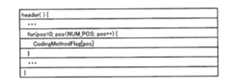
図17Aは、ヘッダの一例の構造を表すシンタクスを示す。ヘッダのシンタクスには、係数位置[pos]毎の符号化方法情報30すなわちフラグCodingMethodFlag[pos]が記述される。係数位置[pos]の値NUM_POSは、係数位置[pos]または係数位置[pos]をグループ分けしたグループ数が記述される。 FIG. 17A shows syntax that represents an exemplary structure of a header. In the header syntax,
図17Bは、ブロックの一例の構造を表すシンタクスを示す。この図17Bに例示されるシンタクスにおいては、画像ブロック10が値NUM_SEGで示される個数のセグメントsegに分割されている。図17Bのシンタクスにおいて、セグメントseg毎に、予測モードpred_modeが記述される。また、各セグメントsegにおいて、係数位置[pos]毎に符号化パラメータを示すインデクス値CodingParamIdx[pos]が記述される。このインデクス値CodingParamIdx[pos]では、例えばゴロム・ライス符号化における符号化パラメータkが記述される。 FIG. 17B shows syntax that represents an exemplary structure of a block. In the syntax illustrated in FIG. 17B, the
さらに、ブロックのシンタクスにおいて、各セグメントsegに含まれる各サブブロックsubblock()が記述される。値NUM_BLKは、セグメントsegに含まれるサブブロックの数を示す。さらにまた、係数位置[pos]において、フラグCodingMethodFlag[pos]が値FALSE、且つ、状態state[pos]が0、且つ、ラン数run[pos]が0より大きい場合に、ラン数run[pos]が記述される。 Further, in the block syntax, each sub-block subblock () included in each segment seg is described. The value NUM_BLK indicates the number of subblocks included in the segment seg. Furthermore, when the coefficient CodingMethodFlag [pos] is the value FALSE, the state state [pos] is 0, and the run number run [pos] is greater than 0 at the coefficient position [pos], the run number run [pos] Is described.
なお、ランレングス符号化に用いられるラン数run[pos]および状態state[pos]は、係数位置[pos]毎に、画像ブロック単位またはセグメント単位で0に初期化される。 Note that the run number run [pos] and the state state [pos] used for run-length encoding are initialized to 0 in units of image blocks or segments for each coefficient position [pos].
図17Cは、サブブロックの一例の構造を表すシンタクスを示す。サブブロックにおいては、係数位置[pos]毎に、フラグCodingMethodFlag[pos]の値に応じて記述内容が変わる。すなわち、フラグCodingMethodFlag[pos]が値TRUEであれば、ゴロム・ライス符号により符号化された量子化変換係数13である、係数coef[blk][pos]が係数位置[pos]に対応して記述される。 FIG. 17C shows syntax that represents an example of the structure of a sub-block. In the sub-block, the description contents change according to the value of the flag CodingMethodFlag [pos] for each coefficient position [pos]. That is, if the flag CodingMethodFlag [pos] is the value TRUE, the coefficient coef [blk] [pos], which is the quantized
一方、サブブロックのシンタクスにおいて、フラグCodingMethodFlag[pos]が値TRUE以外、すなわち値FALSEの場合、状態state[pos]が係数coef[blk][pos]と異なるか否かでさらに記述が変わる。すなわち、状態state[pos]が係数coef[blk][pos]と異なる場合、ランレングス符号化によるラン数runおよび状態stateが、係数位置[pos]に対応して記述される。 On the other hand, in the syntax of the sub-block, when the flag CodingMethodFlag [pos] is other than the value TRUE, that is, the value FALSE, the description further changes depending on whether or not the state state [pos] is different from the coefficient coef [blk] [pos]. That is, when the state state [pos] is different from the coefficient coef [blk] [pos], the run number run and the state state by run-length encoding are described corresponding to the coefficient position [pos].
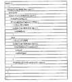
次に、量子化変換係数13を係数位置[pos]毎に符号化する方式により生成される符号化データ14の一例の構造を示す第2のシンタクスの例について、図18Aおよび図18Bを用いて説明する。なお、これら図18Aおよび図18Bにおいては、上述と同様にして、シンタクスを、プログラム言語の1つであるC言語の様式に従い記述している。 Next, a second syntax example showing the structure of an example of encoded
第2のシンタクスによれば、符号化データ14は、ヘッダおよびブロックから構成される。ヘッダは、符号化データ14のヘッダ情報が記述される。ヘッダは、例えば、画像データの1フレームや、一連のフレームからなるシーケンスに対して適用される。ブロックは、符号化データ14における画像ブロック10を構成するデータを含む。 According to the second syntax, the encoded
図18Aは、ヘッダの一例の構造を表すシンタクスを示す。この第2のシンタクスによるヘッダ構造は、図17Aを用いて説明した第1のシンタクスによるヘッダ構造と同一なので、ここでの説明を省略する。 FIG. 18A shows syntax that represents an exemplary structure of a header. Since the header structure based on the second syntax is the same as the header structure based on the first syntax described with reference to FIG. 17A, description thereof is omitted here.
図18Bは、ブロックの一例の構造を表すシンタクスを示す。この第2のシンタクスによるブロックは、図17Bに示した第1のシンタクスによるブロックと異なり、第1および第2の可変長符号化の結果が、小画素ブロック11毎にブロック内に直接的に記述される。なお、ここでは、ブロックのシンタクスにより記述される画像ブロック10に含まれる小画素ブロック11、11、…を、変数blkを用いて小画素ブロック[blk]として説明する。 FIG. 18B shows syntax that represents an exemplary structure of a block. The block with the second syntax is different from the block with the first syntax shown in FIG. 17B, and the results of the first and second variable length encodings are directly described in the block for each
図18Bのシンタクスにおいて、セグメントseg毎に、予測モードpred_modeが記述される。また、各セグメントsegにおいて、係数位置[pos]毎に符号化パラメータを示すインデクス値CodingParamIdx[pos]が記述される。このインデクス値CodingParamIdx[pos]では、例えばゴロム・ライス符号化における符号化パラメータkが記述される。 In the syntax of FIG. 18B, the prediction mode pred_mode is described for each segment seg. In each segment seg, an index value CodingParamIdx [pos] indicating an encoding parameter is described for each coefficient position [pos]. In this index value CodingParamIdx [pos], for example, a coding parameter k in Golomb-Rice coding is described.
係数位置[pos]毎の記述は、フラグCodingMethodFlag[pos]の値に応じて変わる。すなわち、フラグCodingMethodFlag[pos]が値TRUEであれば、ゴロム・ライス符号により符号化された量子化変換係数13である係数coef[blk][pos]が、小画素ブロック11に対応する小画素ブロック[blk]毎に、当該小画素ブロック[blk]における係数位置[pos]に対応して記述される。 The description for each coefficient position [pos] changes according to the value of the flag CodingMethodFlag [pos]. That is, if the flag CodingMethodFlag [pos] is the value TRUE, the coefficient coef [blk] [pos], which is the quantized
一方、フラグCodingMethodFlag[pos]が値TRUE以外、すなわち値FALSEであれば、状態state[pos]が係数coef[blk][pos]と異なるか否かでさらに記述が変わる。すなわち、状態state[pos]が係数coef[blk][pos]と異なる場合、ランレングス符号化によるラン数runおよび状態stateが、係数位置[pos]に対応して記述される。 On the other hand, if the flag CodingMethodFlag [pos] is other than the value TRUE, that is, if the value is FALSE, the description further changes depending on whether or not the state state [pos] is different from the coefficient coef [blk] [pos]. That is, when the state state [pos] is different from the coefficient coef [blk] [pos], the run number run and the state state by run-length encoding are described corresponding to the coefficient position [pos].
また、係数位置[pos]について小画素ブロック[blk]の処理が全て終了した後に、状態stateが0、且つ、ラン数runが0より大きければ、当該係数位置[pos]の記述の後ろに、ラン数run[pos]が記述される。 Further, after the processing of the small pixel block [blk] is completed for the coefficient position [pos], if the state state is 0 and the run number run is larger than 0, after the description of the coefficient position [pos], The run number run [pos] is described.
上述したシンタクスにおいては、可変長符号化方法を切り替えるための情報であるフラグCodingMethodFlagをヘッダに含めているが、これはこの例に限定されない。すなわち、フラグCodingMethodFlagをブロックやサブブロックに含めるようにしてもよい。フラグCodingMethodFlagをブロックに含める場合には、可変長符号化方法の切り替えをセグメント毎に行うことができる。また、フラグCodingMethodFlagをサブブロックに含める場合には、可変長符号化方法の切り替えを小画素ブロック11、11、…毎に行うことができる。同様に、予測モードpred_modeやインデクス値CodingParamIdxをヘッダやサブブロックに含め、シーケンスやフレーム毎、あるいは、小画素ブロック11、11、…毎に予測モードや符号化パラメータを指定するようにしてもよい。 In the syntax described above, the flag CodingMethodFlag, which is information for switching the variable-length encoding method, is included in the header, but this is not limited to this example. That is, the flag CodingMethodFlag may be included in a block or sub-block. When the flag CodingMethodFlag is included in the block, the variable length coding method can be switched for each segment. Further, when the flag CodingMethodFlag is included in the sub-block, the variable-length encoding method can be switched for each of the small pixel blocks 11, 11,. Similarly, the prediction mode pred_mode and the index value CodingParamIdx may be included in the header and sub-block, and the prediction mode and the encoding parameter may be designated for each sequence, each frame, or each
また、図17A〜図17C、ならびに、図18Aおよび図18Bに例示したシンタクスに対し、例えば行間に本実施形態で定義していないシンタクス要素を挿入してもよいし、条件分岐に関する記述をさらに含ませてもよい。例えば、モード情報31がシンタクスに含められる。モード情報31は、上述したように、予測モード情報や、量子化パラメータQP、量子化ステップサイズ、量子化マトリクスなどの量子化処理に関するパラメータを含む量子化情報といった、変換係数以外の復号に必要な情報を含む。 In addition, for example, syntax elements not defined in the present embodiment may be inserted between lines in the syntaxes illustrated in FIGS. 17A to 17C and FIGS. 18A and 18B, and further include descriptions related to conditional branches. You may not. For example,
さらに、シンタクステーブルを複数のテーブルに分割したり、複数に分かれたシンタクステーブルを統合することも可能である。さらにまた、上述したシンタクスにおいて示した各用語は、これらに限定されるものではなく、利用する形態に応じて任意に変更してもよい。 Further, it is possible to divide the syntax table into a plurality of tables, or to integrate a plurality of divided syntax tables. Furthermore, each term shown in the syntax mentioned above is not limited to these, You may change arbitrarily according to the form to utilize.
本実施形態では、第1可変長符号化部123および第2可変長符号化部124に、1シンボルに対して1ビット以上の符号を割り当てる可変長符号化を適用しているが、これはこの例に限定されない。すなわち、第1可変長符号化部123および第2可変長符号化部124のそれぞれに、1シンボルに対して1ビット未満の符号割り当てが可能な可変長符号化を適用させてもよい。このような可変長符号化の例として、コンテキストベースの適応算術符号化であるCABAC(Context−based Adaptive Binary Arithmetic Coding)がある。 In the present embodiment, variable length coding that assigns a code of 1 bit or more to one symbol is applied to the first variable
この場合、第1可変長符号化部123と第2可変長符号化部124とで、算術符号化に適用するコンテキスト(確率テーブル)およびその遷移を異ならせる。コンテキストの遷移が異なる第1可変長符号化部123および第2可変長符号化部124を、スイッチ部122により係数位置毎に切り替えて適用することで、算術符号化において符号化性能を向上させることができる。一例として、変換係数のエントロピーが小さい高周波成分と、当該エントロピーが大きい低周波成分とでコンテクストを異ならせることにより、適切な確率モデルを持つ算術符号化を実現できる。 In this case, the first variable
なお、上述では、量子化および変換部103は、直交変換して得られた変換係数を量子化するように説明したが、これはこの例に限定されない。すなわち、量子化処理を行わずに、直交変換して得られた変換係数をそのままエントロピー符号化部104と、逆量子化および逆変換部105とに供給してもよい。この場合、例えば逆量子化および逆変換部105における逆量子化処理など、量子化処理に対応する他の処理は、全て行わないことになる。 In the above description, the quantization and conversion unit 103 has been described as quantizing the transform coefficient obtained by orthogonal transform, but this is not limited to this example. That is, the transform coefficient obtained by orthogonal transform may be supplied as it is to the
<第2の実施形態>
次に、第2の実施形態について説明する。本第2の実施形態は、動画像データを圧縮符号化した際の、単位時間当たりの発生符号量を一定以下に制御する場合の例である。例えば、動画像データの1フレームで発生する発生符号量を一定以下に制御する。これに限らず、当該所定単位が1または複数のライン単位で発生符号量を制御してもよいし、1フレームを分割したブロック単位で派生符号量を制御してもよい。<Second Embodiment>
Next, a second embodiment will be described. The second embodiment is an example of a case where the amount of generated code per unit time when moving image data is compression-encoded is controlled below a certain level. For example, the amount of generated code generated in one frame of moving image data is controlled to a certain value or less. Not limited to this, the generated code amount may be controlled in units of one or a plurality of lines as the predetermined unit, or the derived code amount may be controlled in block units obtained by dividing one frame.
図19は、本第2の実施形態を適用可能な画像符号化装置2の一例の構成を示すブロック図である。なお、図19において、上述した図1と共通する部分には同一の符号を付し、詳細な説明を省略する。この画像符号化装置2は、上述の第1の実施形態で説明した画像符号化部100を、2パス方式の画像符号化処理に適用した例である。 FIG. 19 is a block diagram illustrating a configuration example of an
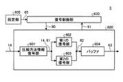
画像符号化装置2は、画像符号化部200、設定部201、符号化制御部130’およびバッファ109を有する。画像符号化装置2は、第1の実施形態による画像符号化部100と同等の機能を有する算出部を複数有し、入力された動画像データ220に対し、各算出部で異なる量子化パラメータQP1、QP2、…、QPNを用いた符号化を試みて、それぞれの発生符号量を求める。その結果、それぞれの算出部で用いた量子化パラメータQP1、QP2、…、QPNのうち、設定部201により予め設定された圧縮率に対応する発生符号量を超えない量子化パラメータQPnを選択する。この選択された量子化パラメータQPnを、第1の実施形態による画像符号化部100と同等の機能を有する符号化部に適用させて、再び当該動画像データ220に対する符号化を行い、符号化データ14の出力を得る。符号化データ14は、バッファ109に一旦溜め込まれ、例えば1フレームを単位として画像符号化装置2から出力される。The
画像符号化部200の一例の構成について、より詳細に説明する。図19において、画像符号化部200は、バッファ202、仮圧縮部203、判定部205および本圧縮部206を有する。 The configuration of an example of the
仮圧縮部203は、ある量子化パラメータQPnにおける発生符号量を算出する算出部204nを複数有する。算出部204nは、上述した第1の実施形態による画像符号化部100と同等の機能を有する。すなわち、算出部204nは、それぞれ、分割部101、減算器102、変換および量子化部103、エントロピー符号化部104、逆量子化および逆変換部105、加算器106、メモリ107および予測部108を有する。The
算出部204nは、入力された画像ブロック10を分割した小画素ブロック11の予測画像信号19に対する予測誤差信号12を求め、予測誤差信号12を直交変換し、得られた変換係数を所定の量子化パラメータQPnで量子化する。そして、算出部204nは、変換係数が量子化された量子化変換係数13をエントロピー符号化部104により可変長符号化した際の発生符号量を求める。The
画像符号化部200においては、複数の算出部2041、2042、…、204Nは、それぞれ、画像符号化部100における変換および量子化部103、ならびに、逆量子化および逆変換部105に相当する部分に対して、異なる量子化パラメータQP1、QP2、…、QPNが適用される。In the
本圧縮部206は、発生符号量が固定的とされた第1の符号化部207を有する。第1の符号化部207は、例えば各画素を固定的な符号長で符号化する。固定的な符号長で符号化を行う単位は、画素単位に限らず、所定数の画素単位、小画素ブロック11単位、画像ブロック10単位などでもよい。 The
本圧縮部206は、さらに、上述した第1の実施形態による画像符号化部100と同等の機能を有する第2の符号化部208を有する。すなわち、第2の符号化部208は、可変長符号を用いて符号化を行う。第2の符号化部208の構成および動作については、上述の画像符号化部100と何ら変わるところがないので、ここでの説明を省略する。 The
設定部201で設定された圧縮率を示す圧縮率情報25が符号化制御部130’に供給される。符号化制御部130’は、上述した第1の実施形態による符号化制御部130と同様に、画像符号化装置2による符号化処理全般を制御するための符号化制御情報40’を、画像符号化部200に供給する。
符号化制御情報40’は、符号化方法情報30や、予測モード情報や量子化に関するパラメータなどによるモード情報31などを含むと共に、圧縮率情報25を含む。符号化方法情報30およびモード情報31は、仮圧縮部203および本圧縮部206にそれぞれ供給される。また、圧縮率情報25は、仮圧縮部203、本圧縮部206および判定部205に供給される。 The
入力された動画像データ220は、バッファ202に一旦格納される。動画像データ220は、バッファ202から読み出される際に、所定サイズの画像ブロック10に分割される。画像ブロック10は、動画像データの1フレームを任意の方法で分割したもので、最小単位が画素、最大単位が1フレーム全体とする。 The input moving
ここで、入力される動画像データ220は、画像符号化装置2において所定の圧縮率を保証する単位とし、フレーム単位の画像データに限らず、1または複数のラインデータや、所定サイズの画像ブロックも含む概念である。また、上述の第1の実施形態では、画像ブロック10は、符号化パラメータkを切り替える単位であるとして説明したが、これはこの例に限定されず、例えば入力される動画像データ220と同一のサイズであってもよい。 Here, the input moving
バッファ202から読み出された画像ブロック10は、評価のために仮圧縮部203に入力され、仮圧縮部203内の複数の算出部2041、2042、…、204Nにそれぞれ供給される。The
ここで、これら複数の算出部2041、2042、…、204Nに対して、上述したように、それぞれ異なる量子化パラメータQP1、QP2、…、QPNが適用されている。算出部204n内の変換および量子化部(図示しない)は、図1を用いて説明した変換および量子化部103と同様に、入力された画像ブロック10のデータと予測データとの差分による予測誤差を直交変換し、得られた変換係数を、量子化パラメータQPnに対応する量子化ステップサイズで除すことで量子化する。Here, the plurality of
図20は、量子化パラメータQPnと、量子化ステップサイズとの関係の例を示す。この例では、量子化ステップサイズは、量子化パラメータQPnの値が大きくなるに連れて間隔が粗くなるように値が設定される。この場合、小さい量子化パラメータQPnでは、より精密に量子化がなされ、大きい量子化パラメータQPnでは、より粗く量子化がなされることになる。FIG. 20 shows an example of the relationship between the quantization parameter QPn and the quantization step size. In this example, the quantization step size is set so that the interval becomes coarse as the value of the quantization parameter QPn increases. In this case, the smaller the quantization parameter QPn, quantization is performed more precisely, the larger quantization parameter QPn, so that coarser quantization is performed.
複数の算出部2041、2042、…、204Nのそれぞれは、適用されている量子化パラメータQPnを用いて供給された画像ブロック10の符号化を行い、符号量201、202、…、20Nを算出する。なお、算出部2041、2042、…、204Nは、符号化データを出力する必要は、無い。Each of the plurality of
算出部2041、2042、…、204Nで算出された符号量201、202、…、20Nは、それぞれ判定部205に供給される。判定部205は、これら符号量201、202、…、20Nを評価し、圧縮率情報25に対応する目標符号量を超えない符号量20mが存在するか否かを判定する。そして、判定結果に応じて、画像ブロック10を固定長で符号化するか、可変長で符号化するかを選択するための圧縮方法情報221を生成する。ここで、目標符号量とは、例えば、入力された動画像データ220内の画像ブロック10に対して均等に符号量を割り当てた場合の符号量(平均割り当て符号量)である。
判定部205は、符号量201、202、…、20Nが全て目標符号量を超えてしまうと判定した場合、画像ブロック10を固定長で符号化する第1の符号化モードを選択する。判定部205は、第1の符号化モードを選択したことを示す圧縮方法情報221を出力する。この圧縮方法情報221は、本圧縮部206に供給される。When the
本圧縮部206は、判定部205から出力された圧縮方法情報221に従い、評価に用いた画像ブロック10をバッファ202から読み出して、第1の符号化部207に入力する。第1の符号化部207は、例えば、画像ブロック10に対して下位ビット切捨てによる線形量子化や空間サンプリングを施すことで、当該画像ブロック10を固定長で符号化する第1の符号化を行う。つまり、1フレームを構成する全ての画像ブロック10、10、…において第1の符号化モードが選択されれば、入力された動画像データ220の当該フレームは、所定のデータサイズ以下での圧縮が保証される。画像ブロック10が第1の符号化部207で符号化された符号化データ14は、本圧縮部206から出力され、バッファ109に一旦格納される。 The
一方、符号量20nが目標符号量を超えない量子化パラメータQPmが存在する場合、判定部205は、画像ブロック10を可変長で符号化する第2の符号化モードを選択する。判定部205は、第2の符号化モードを選択したことを示す圧縮方法情報221を出力する。この圧縮方法情報221は、当該量子化パラメータQPmを示す情報と共に、本圧縮部206に入力される。On the other hand, when there is a quantization parameter QPm where the
本圧縮部206は、判定部205から出力された圧縮方法情報221に従い、評価に用いた画像ブロック10をバッファ202から読み出し、第2の符号化部208に供給する。第2の符号化部208は、上述したように、図1に示した画像符号化部100と同等の機能を有する。第2の符号化部208は、上述の第1の実施形態による方法により、画像ブロック10の直交変換、量子化およびエントロピー符号化を行う。量子化の際には、判定部205から供給された量子化パラメータQPmが用いられる。画像ブロック10が第2の符号化部208で符号化された符号化データ14は、本圧縮部206から出力され、バッファ109に一旦格納される。The
なお、本第2の実施形態においては、画像ブロック10毎に量子化パラメータQPnが異なる。画像ブロック10毎の量子化パラメータQPnは、例えばモード情報31に含められて復号側に伝送される。また、圧縮方法情報221も、例えばモード情報31に含められて符号化データ14に埋め込まれる。圧縮率情報25を示す目標符号量情報をさらにモード情報31に含めて符号化データ14に埋め込むようにしてもよい。In the second embodiment, the quantization parameter QPn is different for each
以上説明したように、上述の第1の実施形態による符号化方法を2パス方式の画像符号化処理にも適用することができる。したがって、2パス方式の画像符号化処理における符号化効率を向上させることができるので、単位時間の発生符号量を一定以下に抑える条件下での画質を向上させることが可能である。 As described above, the encoding method according to the first embodiment described above can be applied to a two-pass image encoding process. Therefore, since the encoding efficiency in the two-pass image encoding process can be improved, it is possible to improve the image quality under the condition that the generated code amount per unit time is kept below a certain level.
<第3の実施形態>
次に、第3の実施形態について説明する。上述した第1および第2の実施形態では、エントロピー符号化の際の量子化変換係数13の変換係数位置毎の符号化方法を、符号化方法情報30を用いて制御していた。これに対して、本実施形態では、エントロピー符号化の際の量子化変換係数13の変換係数位置毎の符号化方法を、符号化を制御するための他のパラメータを用いて制御する。<Third Embodiment>
Next, a third embodiment will be described. In the first and second embodiments described above, the encoding method for each transform coefficient position of the quantized
図21は、本実施形態に適用可能なエントロピー符号化部104’の一例の構成を示すブロック図である。このエントロピー符号化部104’は、上述の第1および第2の実施形態におけるエントロピー符号化部104に対応するものである。なお、図21において、上述した図4と共通する部分には同一の符号を付し、詳細な説明を省略する。 FIG. 21 is a block diagram illustrating an exemplary configuration of the entropy encoding unit 104 'applicable to the present embodiment. The entropy encoding unit 104 'corresponds to the
図21に示されるエントロピー符号化部104’は、係数符号化部110、モード情報変換部302およびモード符号化部112を有する。予測モード情報や量子化に関するパラメータを含むモード情報31がモード情報変換部302およびモード符号化部112に供給される。上述した第2の実施形態による画像符号化部200に対してこのエントロピー符号化部104’を適用する場合には、圧縮率情報25がモード情報変換部302およびモード符号化部112に対してさらに供給される。 The
モード情報変換部302は、供給されたQP情報やモード情報31、圧縮率情報25に基づき、符号化方法情報30を生成し、係数符号化部110に供給する。係数符号化部110は、上述した第1および第2の実施形態と同様にして、この符号化方法情報30に基づき、可変長符号化方法を係数位置毎に切り替えて、量子化変換係数13の符号化を行う。 The mode information conversion unit 302 generates encoding
本実施形態におけるモード情報変換部302の動作について、より詳細に説明する。上述したように、係数符号化部110内の第1可変長符号化部123は、1シンボル毎の符号化を行い、第2可変長符号化部124は、複数シンボルを纏めて符号化することが可能である。したがって、第1可変長符号化部123は、低圧縮率または高画質が求められる領域やブロックのデータを符号化するのに適している。一方、第2可変長符号化部124は、高圧縮率または低画質乃至中画質が求められる領域やブロックのデータを符号化するのに適している。例えば、周波数成分を低周波成分と高周波成分とに分けて、低周波成分の係数に第1の可変長符号化を適用し、高周波成分に第2の可変長符号化を適用することが考えられる。「低周波成分」の範囲および「高周波成分」の範囲を変えることにより、第1の可変長符号化が適用される係数位置の範囲を変えることができる。 The operation of the mode information conversion unit 302 in this embodiment will be described in more detail. As described above, the first variable
本実施形態では、以下の4種類のパラメータにより、係数位置毎に可変長符号化方法を指定するためのフラグCodingMethodFlagを設定する。
(1)量子化パラメータQP
(2)目標符号量
(3)予測方向
(4)画像信号成分In this embodiment, a flag CodingMethodFlag for designating a variable length coding method is set for each coefficient position by the following four types of parameters.
(1) Quantization parameter QP
(2) Target code amount (3) Prediction direction (4) Image signal component
なお、以下では、小画素ブロック11を2画素×2画素とし、直交変換に2×2変換を用いるものとする。したがって、係数位置[pos]は、位置LL、HL、LHおよびHHとして表される。 In the following, it is assumed that the
先ず、(1)の、量子化パラメータQPを用いてフラグCodingMethodFlagを設定する方法について説明する。量子化パラメータQPや目標符号量は、画像データの圧縮率や復号後の画質に密接に関係するパラメータである。そのため、符号化対象領域の量子化パラメータQPや目標符号量の情報を用いることで、可変長符号化方法を指定するためのフラグCodingMethodFlagを設定することが可能である。 First, a method of setting the flag CodingMethodFlag using the quantization parameter QP in (1) will be described. The quantization parameter QP and the target code amount are parameters closely related to the compression rate of image data and the image quality after decoding. Therefore, it is possible to set a flag CodingMethodFlag for designating a variable-length encoding method by using the quantization parameter QP and target code amount information of the encoding target region.
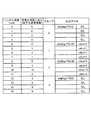
図22Aは、量子化パラメータQPnに対する各係数位置[pos]におけるフラグCodingMethodFlag[pos]の一例の設定を示す。ここで、量子化パラメータQPnは、図20に例示したように、量子化パラメータQPnの値QPが大きくなるに連れ、量子化ステップサイズの間隔が大きくなるように定義されているものとする。Figure 22A illustrates an example setting of a flag CodingMethodFlag [pos] at each coefficient position [pos] for the quantization parameter QPn. Here, the quantization parameter QPn, as illustrated in FIG. 20, taken to the value QP the quantization parameter QPn increases, assumed to be defined as the interval of the quantization step size increases .
圧縮率が低く高画質である、量子化パラメータQPnの値が小さい範囲では、低い空間周波数からより高い空間周波数に対応する係数位置[pos]までフラグCodingMethodFlag[pos]を値TRUE、すなわち、第1可変長符号化部123を選択するように設定する。以降、量子化パラメータQPnの値が大きくなるに連れ、高い空間周波数に対応する係数位置[pos]からフラグCodingMethodFlag[pos]が値FALSEになる割合が増加するように、各係数位置[pos]のフラグCodingMethodFlagが設定される。このように、量子化パラメータQPnに応じて適切な可変長符号化方法を適用することで、符号化効率を向上させることができる。In the range where the compression ratio is low and the image quality is high and the value of the quantization parameter QPn is small, the flag CodingMethodFlag [pos] is set to the value TRUE, that is, the coefficient position [pos] corresponding to the higher spatial frequency from the low spatial frequency. One variable
図22Aの例では、より精密に量子化が行われ、圧縮率が低く高画質の量子化パラメータQP=0およびQP=1の場合には、全ての係数位置[pos]においてフラグCodingMethodFlagを値TRUEに設定し、第1可変長符号化部123を適用させる。量子化パラメータQP=2乃至QP=4の場合には、高周波成分のみからなる係数位置[pos]である位置HHにおいてフラグCodingMethodFlagを値FALSEとして第2可変長符号化部124を適用させ、他の係数位置[pos]ではフラグCodingMethodFlagを値TRUEとして第1可変長符号化部123を適用する。 In the example of FIG. 22A, when the quantization is performed more precisely and the quantization parameter QP = 0 and QP = 1 with low compression ratio and high image quality, the flag CodingMethodFlag is set to the value TRUE at all coefficient positions [pos]. And the first variable
量子化パラメータQP=5乃至QP=7では、低周波成分のみからなる係数位置[pos]である位置LLにおいてフラグCodingMethodFlagを値TRUEとして第1可変長符号化部123を適用させ、他の係数位置[pos]ではフラグCodingMethodFlagを値FALSEとして第2可変長符号化部124を適用する。また、より量子化ステップサイズの大きい量子化パラメータQP=8以上で、全ての係数位置[pos]においてフラグCodingMethodFlagを値FALSEとして第2可変長符号化部124を適用する。 With the quantization parameters QP = 5 to QP = 7, the first variable
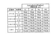
次に、(2)の、目標符号量を用いてフラグCodingMethodFlagを設定する方法について説明する。図22Bは、目標符号量すなわち圧縮率に対する各係数位置[pos]におけるフラグCodingMethodFlag[pos]の一例の設定を示す。圧縮率が低いほど高画質が期待され、圧縮率が高くなるに連れ単位時間当たりの発生符号量が少なくなることが期待される。したがって、圧縮率が低い範囲では、低い空間周波数からより高い空間周波数に対応する係数位置[pos]までフラグCodingMethodFlag[pos]を値TRUEに設定する。以降、圧縮率が高くなるに連れ、高い空間周波数に対応する係数位置[pos]から、フラグCodingMethodFlag[pos]が値FALSEになる割合が増加するように、各係数位置[pos]のフラグCodingMethodFlag[pos]が設定される。このように、圧縮率に応じて適切な可変長符号化方法を適用することで、符号化効率を向上させることができる。 Next, the method (2) of setting the flag CodingMethodFlag using the target code amount will be described. FIG. 22B illustrates an example of setting of a flag CodingMethodFlag [pos] at each coefficient position [pos] with respect to a target code amount, that is, a compression rate. The lower the compression rate, the higher the image quality expected, and the higher the compression rate, the lower the amount of generated code per unit time. Therefore, in the range where the compression rate is low, the flag CodingMethodFlag [pos] is set to the value TRUE from the low spatial frequency to the coefficient position [pos] corresponding to the higher spatial frequency. Thereafter, as the compression rate increases, the coefficient CodingMethodFlag [pos] of each coefficient position [pos] increases from the coefficient position [pos] corresponding to a high spatial frequency so that the ratio of the flag CodingMethodFlag [pos] to the value FALSE increases. pos] is set. Thus, encoding efficiency can be improved by applying an appropriate variable length encoding method according to the compression rate.
図22Bの例では、圧縮率が最も低い(1〜1/2)場合には、全ての係数位置[pos]においてフラグCodingMethodFlagを値TRUEとし、第1可変長符号化部123を適用させる。圧縮率が1/2〜1/4では、高周波成分のみからなる係数位置[pos]である位置HHにおいてフラグCodingMethodFlagを値FALSEとして第2可変長符号化部124を適用させ、他の係数位置[pos]ではフラグCodingMethodFlagを値TRUEとして第1可変長符号化部123を適用する。 In the example of FIG. 22B, when the compression rate is the lowest (1 to 1/2), the flag CodingMethodFlag is set to the value TRUE at all coefficient positions [pos], and the first variable
圧縮率がより高い1/4〜1/6では、低周波成分のみからなる係数位置[pos]である位置LLにおいてフラグCodingMethodFlagを値TRUEとして第1可変長符号化部123を適用させ、他の係数位置[pos]ではフラグCodingMethodFlagを値FALSEとして第2可変長符号化部124を適用する。また、圧縮率が1/6より高い場合には、全ての係数位置[pos]においてフラグCodingMethodFlagを値FALSEとして第2可変長符号化部124を適用する。 When the compression ratio is higher from ¼ to 6, the first variable
例えば、上述した第2の実施形態において、設定部201で設定された圧縮率に応じて各係数位置毎のフラグCodingMethodFlagを設定することができる。第2の符号化部208において、係数の符号化を第1の可変長符号化および第2の可変長符号化の何れを用いて行うかが、この圧縮率に応じた各係数位置毎のフラグCodingMethodFlagにより切り替えられる。 For example, in the second embodiment described above, the flag CodingMethodFlag for each coefficient position can be set according to the compression rate set by the setting unit 201. In the
次に、(3)の、予測方向を用いてフラグCodingMethodFlagを設定する方法について説明する。すなわち、画像符号化部100における予測部108、あるいは、画像符号化部200内の算出部2041、2042、…における予測部108において、画像ブロック10に適用する予測モードの予測方向に応じて、フラグCodingMethodFlagを設定する。Next, a method of setting the flag CodingMethodFlag using the prediction direction (3) will be described. That is, the
例えば、上述の図3Bに例示されるように、予測方向が垂直方向である場合、画像ブロック10における垂直方向の相関は除去される一方、水平方向の相関は、除去されない。したがって、予測方向を垂直方向として求めた予測誤差信号12を直交変換した場合、垂直方向成分は変換係数が小さく、水平方向成分は変換係数が大きくなると考えられる。 For example, as illustrated in FIG. 3B described above, when the prediction direction is the vertical direction, the vertical direction correlation in the
そこで、予測方向が垂直方向である予測モードの場合、係数位置LHのフラグCodingMethodFlagを値TRUEに設定して第1可変長符号化部123を適用させ、係数位置HLのフラグCodingMethodFlagを値FALSEに設定して第2可変長符号化部124を適用させる。 Therefore, in the prediction mode in which the prediction direction is the vertical direction, the flag CodingMethodFlag at the coefficient position LH is set to the value TRUE, the first variable
また、予測方向が上述の図3Aに示す水平方向である予測モードの場合、同様の考え方から、係数位置HLのフラグCodingMethodFlagを値TRUEに設定して第1可変長符号化部123を適用させ、係数位置LHのフラグCodingMethodFlagを値FALSEに設定して第2可変長符号化部124を適用させる。 Also, in the case of the prediction mode in which the prediction direction is the horizontal direction shown in FIG. 3A described above, from the same concept, the first variable
その他の予測方向の予測モードについては、例えば係数位置LLのフラグCodingMethodFlagのみを値TRUEとし、他の係数位置のフラグCodingMethodFlagを値FALSEとする。このように、予測方向に応じて適切な可変長符号化方法を適用することで、符号化効率を向上させることができる。 For prediction modes in other prediction directions, for example, only the flag CodingMethodFlag at the coefficient position LL is set to the value TRUE, and the flags CodingMethodFlag at other coefficient positions are set to the value FALSE. Thus, encoding efficiency can be improved by applying an appropriate variable length encoding method according to a prediction direction.
図22Cは、このようにして設定された、予測方向に対する各係数位置[pos]におけるフラグCodingMethodFlag[pos]の一例の設定を示す。図22Cの例では、予測方向に応じた設定が、圧縮率が1/4〜1/6の場合に限定的に適用されている。 FIG. 22C shows an example of setting of the flag CodingMethodFlag [pos] at each coefficient position [pos] with respect to the prediction direction set in this way. In the example of FIG. 22C, the setting according to the prediction direction is applied in a limited manner when the compression rate is 1/4 to 1/6.
次に、(4)の、画像信号成分に応じてフラグCodingMethodFlag[pos]を設定する方法について説明する。すなわち、上述の(1)〜(3)では、各係数位置[pos]に対するフラグCodingMethodFlag[pos]の設定を、符号化を制御するための他のパラメータに基づき設定している。これはこの例に限定されず、画像信号成分に応じて、係数位置[pos]毎のフラグCodingMethodFlag[pos]を設定してもよい。 Next, the method (4) for setting the flag CodingMethodFlag [pos] according to the image signal component will be described. That is, in the above (1) to (3), the setting of the flag CodingMethodFlag [pos] for each coefficient position [pos] is set based on other parameters for controlling encoding. This is not limited to this example, and a flag CodingMethodFlag [pos] for each coefficient position [pos] may be set according to the image signal component.
画像信号が輝度成分Yと色差成分U、Vとで構成される場合、一般的に、輝度成分Yに情報量が集中し、色差成分U、Vは、輝度成分Yに対して情報量が少ない。そのため、色差成分U、Vは、輝度成分Yと比較して予測処理が容易で、予測誤差が小さい場合が多い。したがって、色差成分U、Vを直交変換した変換係数は、エントロピーが低くなりシンボルがゼロになる傾向が強くなる。そこで、色差成分U、Vに対して第2可変長符号化部124を適用させる割合を、輝度成分Yに対して適用させる割合よりも高く設定することで、符号化効率を向上させることができる。 When an image signal is composed of a luminance component Y and color difference components U and V, generally, the information amount is concentrated on the luminance component Y, and the color difference components U and V have a smaller information amount than the luminance component Y. . For this reason, the color difference components U and V are easier to predict than the luminance component Y, and the prediction error is often small. Therefore, the transform coefficient obtained by orthogonally transforming the color difference components U and V has a strong tendency to have low entropy and zero symbols. Therefore, by setting the ratio of applying the second variable
図22Dは、画像信号成分に対する各係数位置[pos]におけるフラグCodingMethodFlag[pos]の一例の設定を示す。この図22Dの例では、輝度成分Yおよび色差成分U、Vに対する各係数位置[pos]におけるフラグCodingMethodFlag[pos]の設定を、圧縮率に応じて変えている。 FIG. 22D shows an exemplary setting of the flag CodingMethodFlag [pos] at each coefficient position [pos] for the image signal component. In the example of FIG. 22D, the setting of the flag CodingMethodFlag [pos] at each coefficient position [pos] for the luminance component Y and the color difference components U and V is changed according to the compression rate.
すなわち、圧縮率が低い(1〜1/2)場合、色差成分U、Vに対して、高周波成分のみからなる係数位置[pos]である位置HHにおいてフラグCodingMethodFlagを値FALSEとして第2可変長符号化部124を適用させる。また、他の係数位置[pos]では、色差成分U、Vに対して、フラグCodingMethodFlagを値TRUEとして第1可変長符号化部123を適用する。以降、圧縮率が高くなるに連れ、色差成分U、Vに対するフラグCodingMethodFlagを値FALSEに設定する割合を増加させていく。図22Cの例では、圧縮率が1/2〜1/4で、色差成分U、Vに対して低周波成分のみからなる係数位置[pos]である位置LLのみをフラグCodingMethodFlagを値TRUEとして第1可変長符号化部123を適用する。 That is, when the compression rate is low (1 to 1/2), the second variable length code is set with the flag CodingMethodFlag as the value FALSE at the position HH that is the coefficient position [pos] consisting only of the high frequency components for the color difference components U and V. The applying
輝度成分Yについても同様である。輝度成分Yの場合、上述のように色差成分U、Vに比べて情報量が多い傾向があるので、フラグCodingMethodFlagを値TRUEとして第1可変長符号化部123を適用する割合を、色差成分U、Vの場合よりも多くする。 The same applies to the luminance component Y. In the case of the luminance component Y, the amount of information tends to be larger than that of the color difference components U and V as described above. Therefore, the ratio of applying the first variable
本実施形態を適用し、量子化パラメータQPや予測モードを用いてフラグCodingMethodFlagを設定する場合、これら量子化パラメータQPや予測モードを示す情報は、復号時に必要な情報として、モード情報31により復号側に伝送される。そのため、復号側では、フラグCodingMethodFlagを用いなくても、符号化時に量子化変換係数13を第1および第2の可変長符号化のうち何れを用いて可変長符号化したかを知ることができる。したがって、本実施形態の構成では、フラグCodingMethodFlagを復号側に伝送する必要が無く、上述の第1および第2の実施形態における符号化方法符号化部111が不要となり、符号化効率を維持したまま付加情報を削減することが可能となる。これは、画像信号成分を用いてフラグCodingMethodFlagを設定する場合も同様である。 When this embodiment is applied and the flag CodingMethodFlag is set using the quantization parameter QP and the prediction mode, information indicating the quantization parameter QP and the prediction mode is decoded by the
なお、図22Bおよび図22Dの例のように、圧縮率を用いてフラグCodingMethodFlagを設定する場合には、目標符号量を示す情報を別途に復号側に伝送する必要がある。例えば、目標符号量を示す情報(圧縮率情報)を、モード情報31に含めて符号化し、符号化データ14に埋め込むことが考えられる。 Note that when the flag CodingMethodFlag is set using the compression rate as in the examples of FIGS. 22B and 22D, it is necessary to separately transmit information indicating the target code amount to the decoding side. For example, it is conceivable that information indicating the target code amount (compression rate information) is encoded by being included in the
上述では、2×2変換を例に挙げて説明したが、4×4変換などより大きなサイズの直交変換に対しても、本第3の実施形態を適用可能であることはもちろんである。この場合、予測方向に応じてフラグCodingMethodFlagを設定する例では、予測方向として、水平および垂直方向以外に斜め方向をさらに用いてもよい。 In the above description, the 2 × 2 transform has been described as an example, but it is needless to say that the third embodiment can be applied to a larger size orthogonal transform such as a 4 × 4 transform. In this case, in the example in which the flag CodingMethodFlag is set according to the prediction direction, an oblique direction may be further used as the prediction direction in addition to the horizontal and vertical directions.
また、量子化パラメータQP、目標符号量、予測方法および画像信号成分を適宜組み合わせてフラグCodingMethodFlagを設定することも可能である。さらに、係数位置の一部に対して本第3の実施形態によるフラグCodingMethodFlagの設定方法を適用し、係数位置の他の部分は、PSNR(Peak Signal−to−Noise Ratio)や発生符号量、RDO(Rate Distortion Optimisation)を用いてフラグCodingMethodFlagを設定するようにしてもよい。 Further, the flag CodingMethodFlag can be set by appropriately combining the quantization parameter QP, the target code amount, the prediction method, and the image signal component. Furthermore, the setting method of the flag CodingMethodFlag according to the third embodiment is applied to a part of the coefficient position, and the other part of the coefficient position includes PSNR (Peak Signal-to-Noise Ratio), generated code amount, RDO. The flag CodingMethodFlag may be set using (Rate Distortion Optimization).
さらにまた、上述したように、本実施形態によれば、符号化方法符号化部111が省略され、フラグCodingMethodFlagを必ずしも符号化する必要はない。したがって、シンタクス構造は、上述した図17Aおよび図18Aにおいて「CodingMethodFlag[pos]」の記述を省略したものとなる。この場合、図17Bおよび図17Cや、図18BにおけるフラグCodingMethodFlag[pos]による条件判定は、図22A〜図22Dを用いて説明した、フラグCodingMethodFlag[pos]を設定するための条件による判定に置き換わることになる。 Furthermore, as described above, according to the present embodiment, the encoding
<第4の実施形態>
次に、第4の実施形態について説明する。本第4の実施形態は、上述した第1の実施形態による画像符号化装置1に対応する画像復号装置の例である。<Fourth Embodiment>
Next, a fourth embodiment will be described. The fourth embodiment is an example of an image decoding device corresponding to the
図23Aは、本第4の実施形態に適用可能な画像復号装置4の一例の構成を示すブロック図である。画像復号装置4は、画像復号部500、復号制御部530およびバッファ506を有する。復号制御部530に対し、画像復号部500から、供給された各種パラメータ情報や復号処理の結果に基づき出力されるフィードバック情報などによる復号情報80が供給される。また、復号制御部530は、画像復号装置4による復号処理全般を制御するための復号制御情報81を生成し、画像復号部500に供給する。 FIG. 23A is a block diagram illustrating a configuration example of an
画像復号装置3は、図17A〜図17C、あるいは、図18Aおよび図18Bを用いて説明したシンタクスを示すシンタクステーブルを持ち、画像復号部500により、画像符号化装置1から出力された符号化データ14からシンタクステーブルに基づき各符号を取り出して復号し、復号画像データ54を出力する。 The
以下では、符号化は、画像符号化装置1を用い、図17A〜図17Cに示すシンタクスを示すシンタクステーブルに従い、画像ブロック10内の小画素ブロック11を逐次的に処理することにより行われたものとする。 Hereinafter, the encoding is performed by sequentially processing the small pixel blocks 11 in the
画像復号部500は、符号列復号部501、逆量子化および逆変換部502、加算器503、メモリ504および予測部505を有する。画像復号部500に入力された符号化データ14は、符号列復号部501に供給される。符号列復号部501は、シンタクステーブルに基づき符号化データ14による符号列を解読する。これにより、符号列復号部501は、符号化データ14から、フラグCodingMethodFlag[pos](図17A参照)、予測モードpred_mode、インデクス値CodingParamIdx[pos](それぞれ図17B参照)といった符号化パラメータを取り出す。 The
同様に、符号列復号部501は、符号化データ14から、量子化パラメータQPおよび量子化マトリクスといった量子化に必要な情報を含む量子化パラメータ情報を取り出す。この量子化パラメータ情報は、例えばモード情報31に含められて符号化データ14に埋め込まれている。この量子化パラメータは、復号制御部530に供給され、復号制御部530内に保持される。 Similarly, the code
また、符号列復号部501は、符号化データ14から、量子化変換係数13がエントロピー符号化された符号列を取り出す。符号列復号部501は、符号化データ14から取り出した符号化パラメータに基づき、画像ブロック10単位でこの符号列を復号して、各係数位置の量子化変換係数13が復元された復元量子化変換係数51を、小画素ブロック11毎に得る。復元量子化変換係数51は、逆量子化および逆変換部502に供給される。また、符号化データ14から取り出された予測モードpred_modeは、予測モード情報52として予測部505に供給される。 Also, the code
逆量子化および逆変換部502は、復号制御部530から量子化パラメータをロードし、ロードされた量子化パラメータに基づき復元量子化変換係数51に対して逆量子化処理を施して、直交変換の変換係数が復元された復元変換係数を得る。逆量子化および逆変換部502は、さらに、画像符号化装置1で行われた直交変換に対応する逆直交変換処理を、この復元変換係数に対して施し、予測誤差信号12が復元された復元予測誤差信号53を得る。 The inverse quantization and
復元予測誤差信号53は、加算器503に供給され、予測部505から出力される予測画像信号56と加算されて復号小画素ブロック54が生成される。この復号小画素ブロック54は、画像復号部500から出力されバッファ506に溜め込まれると共に、メモリ504に記憶される。メモリ504に記憶された復号小画素ブロック54は、参照画像信号55として、後に復号処理される小画素ブロックの予測に用いられる。バッファ506に溜め込まれた復号小画素ブロック54は、復号処理部530のタイミング制御に従い、例えば1フレーム単位で出力される。 The restored
メモリ504に記憶された復号小画素ブロック54は、参照画像信号55として予測部505に供給される。予測部505は、予測モード情報52に基づき、上述した予測部108と同様にして、参照画像信号55から予測画像信号56を生成する。この予測画像信号56が加算器503に供給される。なお、上述した図1Bに示す画像符号化装置1’のように予測を行わないで生成された符号化データ14を復号する場合には、図23Bに画像復号装置4’として例示されるように、画像復号装置4から予測部505を取り除くことができる。この場合、予測は行われず、逆量子化および逆変換部502から出力される復元予測誤差信号53がそのまま復号小画素ブロック54となる。またこの場合、予測に関する他の構成、すなわち、加算器503およびメモリ504が不要となる。 The decoded
図24は、符号列復号部501の一例の構成を示すブロック図である。符号列復号部501は、分離部510、符号化方法復号部511、係数復号部512およびモード復号部513を有する。符号化データ14は、分離部510に供給される。分離部510は、シンタクステーブルに従い、供給された符号化データ14から、符号化方法情報30が符号化された符号部分とモード情報31が符号化された符号部分とを分離し、それぞれ符号化方方法復号部511およびモード復号部513に供給する。 FIG. 24 is a block diagram illustrating an exemplary configuration of the code
また、分離部510は、符号化データ14から量子化変換係数13が符号化された符号部分を分離して係数復号部512に供給する。これに限らず、分離部510は、符号化データ14を係数復号部512に供給するようにしてもよい。 Further, the
符号化方法復号部511は、供給された符号を復号して符号化方法情報30(フラグCodingMethodFlag[pos])を得る。この符号化方法情報30は、符号化された量子化変換係数13を復号する際の復号方法を示す復号方法情報58として出力され、係数復号部512に供給される。 The encoding
係数復号部512は、分離部510から供給された符号化データ14を、復号方法情報58に基づき復号し、量子化変換係数13が復号された復元量子化変換係数51を出力する。また、モード復号部513は、分離部510から供給された符号を復号し、モード情報31を得る。モード情報31は、上述したように、量子化パラメータQPおよび量子化マトリクスなどの量子化に関するパラメータや、予測モード情報52といった、変換係数以外の復号に必要な情報を含む。量子化に関するパラメータは、復号制御部530に供給される。また、予測モード情報52は、上述のように予測部505に供給される。 The
図25は、係数復号部512の一例の構成を示すブロック図である。係数復号部512は、係数位置抽出部520、復号方法判定部521およびスイッチ部522、ならびに、第1可変長復号部523および第2可変長復号部524を有する。 FIG. 25 is a block diagram illustrating an exemplary configuration of the
係数位置抽出部520は、上述の第1の実施形態において図5を用いて説明した係数位置抽出部120と同様の機能を有する。すなわち、係数位置抽出部520は、供給された符号化データ14をスイッチ部522の入力端522Aに供給すると共に、当該符号化データ14から、復号対象の符号の係数位置を示す係数位置情報60を取得する。例えば、図17Bに例示したブロックのシンタクスに従い、サブブロック(小画素ブロック)毎に、変換係数の復号処理を逐次計数することで、係数位置を知ることができる。なお、係数位置情報60は、図6Aおよび図6Bを用いて説明したように、小画素ブロック内でグループ分けした位置グループで表してもよい。 The coefficient position extraction unit 520 has a function similar to that of the coefficient position extraction unit 120 described with reference to FIG. 5 in the first embodiment. That is, the coefficient position extraction unit 520 supplies the supplied encoded
スイッチ部522は、後述する復号方法判定部521から出力される切替信号61により、出力端522Bおよび522Cが切り替えられる。出力端522Bおよび522Cに対して、第1可変長復号部523および第2可変長復号部524がそれぞれ接続される。すなわち、入力端522Aに供給された符号化データ14は、切替信号61に応じて第1可変長復号部523および第2可変長復号部524の何れか一方に、選択的に供給される。 In the
係数位置情報60は、復号方法判定部521に供給される。また、復号方法判定部521には、復号方法情報58も供給される。復号方法判定部521は、係数位置情報60と復号方法情報58とに基づき、係数位置毎または位置グループ毎に切替信号61を出力し、スイッチ部522に供給する。 The
これにより、スイッチ部522が復号方法情報58に基づき係数位置または位置グループ単位に切り替えられ、係数位置抽出部520から出力された符号化データ14が、係数位置または位置グループ単位で第1可変長復号部523または第2可変長復号部524に対して適応的に供給される。 Accordingly, the
第1可変長復号部523は、供給された符号化データ14に対して、符号化の際に第1可変長符号化部123でなされた符号化に対応する復号処理(第1の可変長復号と呼ぶ)を行う。すなわち、第1可変長符号化部123は、1シンボルずつ符号化する1シンボル単位符号化を行うため、第1可変長復号部523は、1シンボルずつ復号する1シンボル単位復号方法により符号化データ14に対する復号処理を行い、復元量子化変換係数51を出力する。例えば、第1可変長符号化部123でゴロム・ライス符号化が用いられた場合には、符号化パラメータkを復号し、当該符号化パラメータkを用いてシンボルを復号する。 The first variable length decoding unit 523 performs decoding processing (first variable length decoding) corresponding to the encoding performed by the first variable
第2可変長復号部524は、供給された符号化データ14に対して、符号化の際に第2可変長符号化部124でなされた符号化に対応する復号処理(第2の可変長復号と呼ぶ)を行う。すなわち、第2可変長符号化部124は、複数のシンボルをまとめて符号化する複数シンボル一括符号化を行うため、第2可変長復号部524は、符号列を復号して複数シンボルを纏めて出力する複数シンボル一括復号を行い、復元量子化変換係数51を出力する。例えば、第2可変長符号化部124でランレングス符号化が用いられた場合には、一連のシンボル群は、そのデータの値(value)とラン数(run)で表現されている。 The second variable length decoding unit 524 decodes the supplied encoded
図26は、ランレングス符号を復号する一例の処理手順を示すフローチャートである。この図26に例示されるフローチャートにおける各処理は、第2可変長復号部524において実行される。なお、ここでは、復号対象シンボルの総数NUM_MAXが既知であるとする。 FIG. 26 is a flowchart illustrating an exemplary processing procedure for decoding a run-length code. Each process in the flowchart illustrated in FIG. 26 is executed by the second variable length decoding unit 524. Here, it is assumed that the total number NUM_MAX of decoding target symbols is known.
先ず、符号化対象シンボル位置numと、状態stateとを0に設定して初期化する(ステップS401)。次に、ラン数runを復号し(ステップS402)、次のステップS403で、復号されたラン数runが0より大きいか否かを判定する。若し、ラン数runが0より大きいと判定された場合(ステップS403の「YES」)、処理はステップS404に移行される。 First, the encoding target symbol position num and the state state are set to 0 and initialized (step S401). Next, the run number run is decoded (step S402), and in the next step S403, it is determined whether or not the decoded run number run is greater than zero. If it is determined that the run number run is greater than 0 (“YES” in step S403), the process proceeds to step S404.
ステップS404では、復号対象シンボルに対して状態stateの値を代入する。そして、次のステップS405でラン数runを1だけデクリメントし、さらに次のステップS406で符号化対象シンボル位置numを1だけインクリメントする。そして、次のステップS407で、符号化対象シンボル位置numを示す値が復号対象のシンボル総数NUM_MAXを示す値を超えたか否かが判定される。若し、超えていないと判定されたら(ステップS407の「NO」)、処理はステップS403に戻され、ラン数runが0より大きいか否かが判定される。 In step S404, the value of the state state is substituted for the decoding target symbol. Then, in the next step S405, the run number run is decremented by 1, and in the next step S406, the encoding target symbol position num is incremented by 1. Then, in the next step S407, it is determined whether or not the value indicating the encoding target symbol position num exceeds the value indicating the decoding target symbol total number NUM_MAX. If it is determined that it has not exceeded (“NO” in step S407), the process returns to step S403 to determine whether or not the run number run is greater than zero.
一方、ステップS407で、符号化対象シンボル位置numを示す値が復号対象のシンボル総数NUM_MAXを示す値を超えたと判定されたら、全ての復号対象シンボルに対する処理が終了したとされ、一連の処理が終了される。 On the other hand, if it is determined in step S407 that the value indicating the encoding target symbol position num exceeds the value indicating the total number of decoding target symbols NUM_MAX, it is determined that the processing for all the decoding target symbols is completed, and the series of processing ends. Is done.
上述のステップS403でラン数runが0であると判定されたら、処理はステップS408に移行される(ステップS403の「NO」)。ステップS408では、次の符号が、上述の第2可変長符号化部124で保持された以外のシンボルにおいてその値(value)を符号化するのに用いた符号化方法(例えばゴロム・ライス符号化)に対応する復号方法により復号され、復号された値yが復号対象シンボルに代入される。そして、次のステップS409で、値yが状態stateに代入され、さらに次のステップS410で符号化対象シンボル位置numを1だけインクリメントする。 If it is determined in step S403 that the run number run is 0, the process proceeds to step S408 (“NO” in step S403). In step S408, the next code is an encoding method (for example, Golomb-Rice encoding) used to encode the value (value) in symbols other than those held in the second variable
ステップS410で符号化対象シンボル位置numがインクリメントされたら、処理はステップS411に移行され、符号化対象シンボル位置numを示す値が復号対象のシンボル総数NUM_MAXを示す値を超えたか否かが判定される。若し、超えていないと判定されたら(ステップS412の「NO」)、処理はステップS402に戻され、次のラン数runが復号される。 When the encoding target symbol position num is incremented in step S410, the process proceeds to step S411, and it is determined whether or not the value indicating the encoding target symbol position num exceeds the value indicating the decoding target symbol total number NUM_MAX. . If it is determined that it has not exceeded (“NO” in step S412), the process returns to step S402, and the next run number run is decoded.
一方、ステップS411で、符号化対象シンボル位置numを示す値が復号対象のシンボル総数NUM_MAXを示す値を超えたと判定されたら、全ての復号対象シンボルに対する処理が終了したとされ、一連の処理が終了される。 On the other hand, if it is determined in step S411 that the value indicating the encoding target symbol position num has exceeded the value indicating the total number of decoding target symbols NUM_MAX, it is determined that the processing for all the decoding target symbols is completed, and the series of processing ends. Is done.
なお、この図26のフローチャートに示す処理において、上述した図8のフローチャートによる処理と同様に、状態stateの値を0に固定的としてもよい。 In the process shown in the flowchart of FIG. 26, the value of the state state may be fixed to 0 as in the process of the flowchart of FIG.
次に、シンタクスに従った復号処理の例について、より具体的に説明する。先ず、上述した図17A〜図17Cに示されるシンタクスに従い、画像ブロック10内の小画素ブロック11を逐次的に符号化した符号化データ14を復号する処理について説明する。 Next, an example of decoding processing according to syntax will be described more specifically. First, a process of decoding the encoded
既に説明したように、この場合のシンタクスは、ヘッダ(図17A参照)と、ブロック(図17B参照)と、サブブロック(図17C参照)の各シンタクスから構成される。サブブロックのシンタクスは、ブロックのシンタクスに埋め込まれている。ヘッダのシンタクスは、ヘッダ情報が記述される。ブロックのシンタクスは、画像ブロック10毎に必要とされるデータが記述される。また、サブブロックのシンタクスは、小画素ブロック11毎に必要とされるデータが記述される。 As already described, the syntax in this case is composed of a header (see FIG. 17A), a block (see FIG. 17B), and a sub-block (see FIG. 17C). The sub-block syntax is embedded in the block syntax. The header syntax describes header information. The block syntax describes data required for each
例えば、復号制御部530は、符号化データ14に対する復号処理を、これらのシンタクスに従い制御することで、符号化データ14を適切に復号することができる。 For example, the decoding control unit 530 can appropriately decode the encoded
図17Aに示すヘッダのシンタクスは、係数位置[pos]毎の可変長復号方法を切り替えるためのフラグCodingMethodFlag[pos]が記述される。図17Aにおいて、値NUM_POSは、係数位置の数、若しくは、係数位置グループの数である。 The header syntax shown in FIG. 17A describes a flag CodingMethodFlag [pos] for switching the variable length decoding method for each coefficient position [pos]. In FIG. 17A, the value NUM_POS is the number of coefficient positions or the number of coefficient position groups.
図17Bに示すブロックのシンタクスでは、画像ブロック毎の予測モードpred_modeや、係数位置[pos]毎の符号化パラメータ(ゴロム・ライス符号化における符号化パラメータkなど)であるインデックス値CodingParamIdx[pos]が明記される。さらに、画像ブロック内の小画素ブロック[blk]単位に変換係数の復号を行うサブブロックsubblock()が埋め込まれる。値NUM_BLKは、画像ブロック内の小画素ブロックの数である。 In the block syntax shown in FIG. 17B, an index value CodingParamIdx [pos], which is a prediction mode pred_mode for each image block, and a coding parameter for each coefficient position [pos] (such as a coding parameter k in Golomb-Rice coding). It is clearly stated. Furthermore, a sub-block subblock () for decoding transform coefficients is embedded in units of small pixel blocks [blk] in the image block. The value NUM_BLK is the number of small pixel blocks in the image block.
予測モードpred_modeやインデックス値CodingParamIdx[pos]は、小画素ブロックを複数纏めたセグメントseg毎に切り替えて記されていてもよい。図17Bに示すシンタクスでは、画像ブロックをNUM_SEG個のセグメントsegに分割している。なお、ランレングス符号化を用いた復号に用いられるラン数runおよび状態stateは、画像ブロック単位およびセグメント単位で0に初期化される。 The prediction mode pred_mode and the index value CodingParamIdx [pos] may be described by switching for each segment seg in which a plurality of small pixel blocks are grouped. In the syntax shown in FIG. 17B, the image block is divided into NUM_SEG segments seg. Note that the run number run and state state used for decoding using run-length encoding are initialized to 0 in image block units and segment units.
図17Cに示すサブブロックのシンタクスでは、小画素ブロック毎の変換係数が記述される。図17Cに示す通り、係数位置[pos]毎に可変長復号方法を切り替えるためのフラグCodingMethodFlag[pos]を判定する。その結果、フラグCodingMethodFlag[pos]が値TRUEであると判定されたら、ゴロム・ライス符号化などの1シンボルずつ復号する復号方法である第1の可変長復号が適用される。この場合、インデックス値CodingParamIdx[pos]を用いて小画素ブロック[blk]の係数位置[pos]における係数coef[blk][pos]が復号される。 In the sub-block syntax shown in FIG. 17C, a transform coefficient for each small pixel block is described. As shown in FIG. 17C, a flag CodingMethodFlag [pos] for switching the variable length decoding method is determined for each coefficient position [pos]. As a result, if it is determined that the flag CodingMethodFlag [pos] is the value TRUE, first variable length decoding, which is a decoding method for decoding one symbol at a time, such as Golomb-Rice encoding, is applied. In this case, the coefficient coef [blk] [pos] at the coefficient position [pos] of the small pixel block [blk] is decoded using the index value CodingParamIdx [pos].
一方、フラグCodingMethodFlag[pos]が値FALSEであると判定されたら、ランレングス符号化などの複数シンボルを纏めて復号可能な第2可変長復号が適用される。この場合、係数coef[blk][pos]が状態state[pos]と等しければ、ラン数run[pos]に1が加算され復号データは示されない。 On the other hand, if it is determined that the flag CodingMethodFlag [pos] is the value FALSE, second variable length decoding capable of decoding a plurality of symbols collectively, such as run length encoding, is applied. In this case, if the coefficient coef [blk] [pos] is equal to the state state [pos], 1 is added to the run number run [pos] and the decoded data is not shown.
また、係数coef[blk][pos]が状態state[pos]と等しくなければ、ラン数run[pos]と状態state[pos]とがフラグCodingMethodFlag[pos]により切り替えられる可変長復号方法により復号される。そして、ラン数run[pos]に対して0が代入され、状態state[pos]に対して係数coef[blk][pos]が代入される。 If the coefficient coef [blk] [pos] is not equal to the state state [pos], the run number run [pos] and the state state [pos] are decoded by the variable length decoding method switched by the flag CodingMethodFlag [pos]. The Then, 0 is substituted for the run number run [pos], and the coefficient coef [blk] [pos] is substituted for the state state [pos].
全ての小画素ブロックの処理が終わったら、第2可変長復号が適用される係数位置[pos]においてラン数run[pos]が0以上の値の場合のみ、ラン数run[pos]が記述される。 When all the small pixel blocks have been processed, the run number run [pos] is described only when the run number run [pos] is 0 or more at the coefficient position [pos] to which the second variable length decoding is applied. The
次に、上述した図18Aおよび図18Bに示されるシンタクスに従い、量子化変換係数13を係数位置[pos]毎に符号化した符号化データ14を復号する処理について説明する。 Next, a process of decoding the encoded
既に説明したように、この場合のシンタクスは、ヘッダ(図18A参照)およぼブロック(図18B参照)の各シンタクスから構成される。ヘッダのシンタクスは、図17Aと同様のヘッダ情報が記述される。ブロックは、符号化データ14における画像ブロック10を構成するデータを含む。 As already described, the syntax in this case is composed of each syntax of a header (see FIG. 18A) and a block (see FIG. 18B). In the header syntax, header information similar to that in FIG. 17A is described. The block includes data constituting the
図18Bに示すブロックのシンタクスでは、図17Bを用いて説明したブロックのシンタクスと異なり、係数位置[pos]毎に処理を行う。先ず、係数位置[pos]毎に可変長復号方法を切り替えるためのフラグCodingMethodFlag[pos]を判定する。その結果、フラグCodingMethodFlag[pos]が値TRUEであると判定されたら、係数位置[pos]の変換係数は全てゴロム・ライス符号化などの1シンボルずつ復号する復号方法である第1の可変長復号が適用される。この場合、インデックス値CodingParamIdx[pos]を用いて小画素ブロック[blk]の係数位置[pos]における係数coef[blk][pos]が復号される。 In the block syntax shown in FIG. 18B, processing is performed for each coefficient position [pos], unlike the block syntax described with reference to FIG. 17B. First, a flag CodingMethodFlag [pos] for switching the variable length decoding method is determined for each coefficient position [pos]. As a result, if it is determined that the flag CodingMethodFlag [pos] is the value TRUE, the first variable length decoding which is a decoding method for decoding all the transform coefficients at the coefficient position [pos] one symbol at a time, such as Golomb-Rice coding. Applies. In this case, the coefficient coef [blk] [pos] at the coefficient position [pos] of the small pixel block [blk] is decoded using the index value CodingParamIdx [pos].
一方、フラグCodingMethodFlag[pos]が値FALSEであると判定されたら、係数位置[pos]における変換係数は、全てランレングス符号化などの複数シンボルを纏めて復号可能な第2可変長復号が適用される。この場合、係数coef[blk][pos]が状態state[pos]と等しければ、ラン数run[pos]に1が加算され復号データは示されない。 On the other hand, if it is determined that the flag CodingMethodFlag [pos] is the value FALSE, the second variable length decoding capable of decoding a plurality of symbols such as run length coding is applied to all the transform coefficients at the coefficient position [pos]. The In this case, if the coefficient coef [blk] [pos] is equal to the state state [pos], 1 is added to the run number run [pos] and the decoded data is not shown.
また、係数coef[blk][pos]が状態state[pos]と等しくなければ、ラン数run[pos]と状態state[pos]とがフラグCodingMethodFlag[pos]により切り替えられる可変長復号方法により復号される。そして、ラン数run[pos]に対して0が代入され、状態state[pos]に対して係数coef[blk][pos]が代入される。 If the coefficient coef [blk] [pos] is not equal to the state state [pos], the run number run [pos] and the state state [pos] are decoded by the variable length decoding method switched by the flag CodingMethodFlag [pos]. The Then, 0 is substituted for the run number run [pos], and the coefficient coef [blk] [pos] is substituted for the state state [pos].
全ての小画素ブロックの処理が終わったら、第2可変長復号が適用される係数位置[pos]においてラン数run[pos]が0以上の値の場合のみ、ラン数run[pos]が記述される。 When all the small pixel blocks have been processed, the run number run [pos] is described only when the run number run [pos] is 0 or more at the coefficient position [pos] to which the second variable length decoding is applied. The
なお、上述では、符号化を、第1可変長符号化部123および第2可変長符号化部124に対して、1シンボルに対して1ビット以上の符号を割り当てる可変長符号化により行った場合の復号処理について説明した。これはこの例に限定されず、符号化を、CABACといった、1シンボルに対して1ビット未満の符号割り当てが可能な可変長符号化を用いて行った場合にも、本第4の実施形態による復号処理を適用可能である。 In the above description, encoding is performed by variable-length coding in which a code of 1 bit or more is assigned to one symbol for the first variable-
この場合、上述したように、符号化の際に、算術符号化に適用するコンテキストおよびその遷移が異なる第1可変長符号化部123および第2可変長符号化部124が、スイッチ部122により係数位置毎に切り替えて適用される。したがって、復号側でもこれに対応し、第1可変長復号部523と第2可変長復号部524とで、算術符号化に適用するコンテキストおよびその遷移を、第1可変長符号化部123および第2可変長符号化部124にそれぞれ対応させて異ならせる。そして、係数位置毎に、第1可変長復号部523と第2可変長復号部524とを切り替えて適用する。符号化の際に、係数位置毎に纏めた順序で符号化を行なうことで、コンテクスト切り替えの頻度が低下して、復号処理の複雑度を低減させることができる。 In this case, as described above, at the time of encoding, the first variable
<第5の実施形態>
次に、第5の実施形態について説明する。本第5の実施形態は、上述した第2の実施形態による画像符号化装置2に対応する画像復号装置の例である。<Fifth Embodiment>
Next, a fifth embodiment will be described. The fifth embodiment is an example of an image decoding device corresponding to the
図27は、本第5の実施形態に適用可能な画像復号装置5の一例の構成を示すブロック図である。画像復号装置5は、画像復号部600、設定部605および復号制御部630を有する。復号制御部630に対し、画像復号部600から、供給された各種パラメータ情報や復号処理の結果に基づき出力されるフィードバック情報などによる復号情報91が供給される。また、復号制御部630は、画像復号装置5による復号処理全般を制御するための復号制御情報90を生成し、画像復号部600に供給する。 FIG. 27 is a block diagram illustrating a configuration example of the
画像復号装置5は、図17A〜図17C、あるいは、図18Aおよび図18Bを用いて説明したシンタクスを示すシンタクステーブルを持ち、画像復号部600により、画像符号化装置2から出力された符号化データ14からシンタクステーブルに基づき各符号を取り出して復号し、復号画像データ63を出力する。 The
以下では、符号化は、画像符号化装置2を用い、図17A〜図17Cに示すシンタクスを示すシンタクステーブルに従い行われたものとする。 Hereinafter, it is assumed that the encoding is performed using the
設定部605は、符号化データ14の圧縮率を示す圧縮率情報65を、復号制御部630に対して設定する。この圧縮率情報65は、復号制御情報90に含められて第1の復号部602および第2の復号部603にそれぞれ設定される。圧縮率情報65は、設定部605を入力手段として予め第1の復号部602および第2の復号部603に対して設定しておくことができる。これに限らず、符号化データ14に、例えばモード情報31に含められて埋め込まれた目標符号量情報を圧縮率情報65として、後述する圧縮方法情報復号部601で復号して設定してもよい。 The
画像復号部600は、圧縮方法情報復号部601、第1の復号部602、第2の復号部603、バッファ604を有する。画像復号部600に入力された符号化データ14が圧縮方法情報復号部601に供給される。圧縮方法情報復号部601は、供給された符号化データ14から、シンタクスに従いモード情報31を取り出し、モード情報31に含められた圧縮方法情報221を取得する。取得された圧縮方法情報221は、復号方法切替情報61として、符号化データ14と共に第1の復号部602および第2の復号部603にそれぞれ供給される。復号方法切替情報61は、符号化データ14の復号を第1の復号部602および第2の復号部603の何れで行うかを、画像ブロック10単位で示す。画像復号部600は、この復号方法切替情報61に従い、符号化データ14の復号を第1の復号部602および第2の復号部603の何れで行うかを選択する。 The
第1の復号部602は、上述の第2の実施形態における第1の符号化部207に対応する。すなわち、第1の復号部602は、第1の符号化部207による符号化処理と逆の処理を行い、符号化データ14を復号する。より具体的な例として、第1の復号部602は、第1の符号化部207に対応し、符号化データ14に対して、画像ブロック10単位で下位ビット補填による逆量子化や、空間補間処理を施して復号処理を行い、復号画像ブロック62を得る。この復号画像ブロック62は、バッファ604に記憶される。 The first decoding unit 602 corresponds to the
第2の復号部603は、上述の第2の実施形態における第2の符号化部208に対応するもので、図23に示した画像復号部600と同等の機能を有する。すなわち、第2の復号部603は、第2の符号化部208による符号化処理と逆の処理を行って符号化データ14を復号し、復号画像ブロック62を得る。この復号画像ブロック62は、バッファ604に記憶される。バッファ604に記憶された復号画像ブロック62、62、…は、復号制御部630に出力タイミングを制御されて、復号画像データ63として出力される。 The second decoding unit 603 corresponds to the
第2の復号部603において、符号化データ14の復号を第1の可変長復号および第2の可変長復号のうち何れを用いて行うかは、設定部605で設定された圧縮率情報65に基づき、例えば、図22Bを用いて説明した、目標符号量を用いてフラグCodingMethodFlagを設定する方法に従い決めることができる。 In the second decoding unit 603, which one of the first variable length decoding and the second variable length decoding is used to decode the encoded
<第6の実施形態>
次に、第6の実施形態について説明する。本第6の実施形態は、上述した第3の実施形態による画像符号化装置に対応する画像復号装置の例である。本第6の実施形態による画像復号装置は、図23を用いて説明した第4の実施形態による画像復号装置4の構成に対して符号列復号部501の構成が異なるのみであるので、以下では、この点を中心に説明する。<Sixth Embodiment>
Next, a sixth embodiment will be described. The sixth embodiment is an example of an image decoding device corresponding to the image coding device according to the third embodiment described above. The image decoding apparatus according to the sixth embodiment is different only in the configuration of the code
図28は、本第6の実施形態による符号列復号部700の一例の構成を示すブロック図である。なお、図28において、上述した図24と共通する部分には同一の符号を付し、詳細な説明を省略する。図29に例示されるように、この符号列復号部700を図23に示す画像復号装置4における符号列復号部501と置き換えることで、本第6の実施形態による画像復号装置6とする。 FIG. 28 is a block diagram illustrating an exemplary configuration of the code
符号列復号部700は、分離部514、係数復号部512、モード復号部513およびモード情報変換部515を有する。符号列復号部700に入力された符号化データ14は、分離部514に供給される。分離部514は、シンタクステーブルに従い、供給された符号化データ14からモード情報31が符号化された符号部分を分離し、モード復号部513に供給する。また、分離部514は、符号化データ14から量子化変換係数13が符号化された符号部分を分離して係数復号部512に供給する。これに限らず、分離部514は、供給された符号化データ14を係数復号部512に供給するようにしてもよい。 The code
モード復号部513は、分離部514から供給された符号を復号してモード情報31を得る。このモード情報31は、上述したように、量子化パラメータQPおよび量子化マトリクスなどの量子化に関するパラメータや、予測モード情報52といった、変換係数以外の復号に必要な情報を含む。モード情報31は、モード情報変換部515に供給される。 The
モード情報変換部515は、供給されたモード情報31から復号方法情報58を生成し、係数復号部512に供給する。係数復号部512は、分離部514から供給された符号化データ14を、復号方法情報58に基づき復号し、量子化変換係数13が復号された復元量子化変換係数51を出力する。すなわち、係数復号部512は、復号方法情報58に従い、1シンボルずつの復号を行う第1の復号方法と、係数位置毎に纏めて復号を行う第2の復号方法とを、係数位置単位で切り替えて、符号化データ14の復号を行う。 The mode
モード情報変換部515の処理について、より詳細に説明する。モード情報変換部515は、モード復号部513から供給されたモード情報31に、符号化データ14の符号化の際に符号化方法情報30として用いられたデータとして含まれる、量子化パラメータQP、予測モード情報および/または目標符号量情報に基づき復号方法情報58を生成する。 The process of the mode
具体的な例として、図22A〜図22Dを用いて説明したような、モード情報31に含まれる量子化パラメータQP、圧縮率(目標符号量)および予測方向や、画像信号成分(輝度成分Y、色差成分U、V)のうち、符号化の際に用いられた情報に基づき、第1の復号方法および第2の復号方法のうち何方を選択するかを示すフラグCodingMethodFlag[pos]を生成する。 As specific examples, the quantization parameter QP, the compression rate (target code amount) and the prediction direction included in the
本第6の実施形態によれば、変換係数の復号方法を示す情報を符号化側から伝送する必要が無い。そのため、符号化効率を維持したまま付加情報を削減することが可能となる。また、復号方法を指定するためのフラグCodingMethodFlagを復号する必要が無いので、既に説明したように、シンタクスにおいて、フラグCodingMethodFlag[pos]の記述が省略できる。 According to the sixth embodiment, there is no need to transmit information indicating the transform coefficient decoding method from the encoding side. Therefore, it is possible to reduce the additional information while maintaining the encoding efficiency. Further, since it is not necessary to decode the flag CodingMethodFlag for designating the decoding method, the description of the flag CodingMethodFlag [pos] can be omitted in the syntax as described above.
上述した各実施形態は、例えば1のLSI(Large−Scale Integration)内に関連する他の画像処理回路と共に組み込む場合に、用いて好適である。勿論、これに限らず、上述の各実施形態による画像符号化装置および画像復号装置は、単独で構成されていてもよい。また、符号化データ14は、有線または無線といった伝送路を介して画像符号化装置から画像復号装置に伝送されてもよいし、光ディスク、半導体メモリといった記憶媒体を介して画像符号化装置から画像復号装置に渡されてもよい。 Each of the above-described embodiments is suitable for use when incorporated together with other image processing circuits related to one LSI (Large-Scale Integration), for example. Of course, the present invention is not limited to this, and the image encoding device and the image decoding device according to each of the above-described embodiments may be configured independently. The encoded
<他の実施形態>
さらに、上述した各実施形態による画像符号化装置または画像復号装置は、ハードウェアのみならず一部または全部をプログラムによりソフトウェア的に構成してもよい。ソフトウェアで構成する場合、画像符号化装置または画像復号装置の各機能をコンピュータに実行させるためのプログラムが、例えば、CPU(Central Processing Unit)などの制御装置と、ROM(Read Only Memory)やRAM(Random Access Memory)などの記憶装置と、HDD(ハードディスクドライブ)、光ディスクドライブ装置などの外部記憶装置と、ディスプレイ装置に表示信号を出力する表示制御装置と、キーボードやマウスなどを接続したり、他のディジタル信号の入出力を行う入出力I/Fを備えたコンピュータにインストールされる。このコンピュータは、通信ネットワークに接続するための通信I/Fをさらに備えてもよい。<Other embodiments>
Furthermore, the image encoding device or the image decoding device according to each of the above-described embodiments may be configured not only as hardware but also partly or entirely as a software program. When configured by software, a program for causing a computer to execute each function of the image encoding device or the image decoding device includes, for example, a control device such as a CPU (Central Processing Unit), a ROM (Read Only Memory), a RAM ( Connect a storage device such as Random Access Memory), an external storage device such as an HDD (Hard Disk Drive) or an optical disk drive device, a display control device that outputs a display signal to the display device, a keyboard or a mouse, It is installed in a computer having an input / output I / F for inputting / outputting digital signals. The computer may further include a communication I / F for connecting to a communication network.
当該プログラムは、例えばインストール可能な形式または実行可能な形式のファイルでCD(Compact Disk)、フレキシブルディスク(FD)、DVD(Digital Versatile Disk)などのコンピュータで読み取り可能な記録媒体に記録されて提供される。 The program is provided as a file in an installable or executable format and recorded on a computer-readable recording medium such as a CD (Compact Disk), a flexible disk (FD), or a DVD (Digital Versatile Disk). The
また、各実施形態による画像符号化装置または画像復号装置をコンピュータ上で実現するためのプログラムを、インターネットなどのネットワークに接続されたコンピュータ上に格納し、ネットワーク経由でダウンロードさせることにより提供するように構成してもよい。また、各実施形態による画像符号化装置または画像復号装置をコンピュータ上で実現するためのプログラムを、インターネットなどのネットワーク経由で提供または配布するように構成してもよい。 Further, a program for realizing the image encoding device or the image decoding device according to each embodiment on a computer is stored on a computer connected to a network such as the Internet, and is provided by being downloaded via the network. It may be configured. In addition, a program for realizing the image encoding apparatus or the image decoding apparatus according to each embodiment on a computer may be configured to be provided or distributed via a network such as the Internet.
また、各実施形態による画像符号化装置または画像復号装置をコンピュータ上で実現するためのプログラムを、ROMなどに予め組み込んで提供するように構成してもよい。 In addition, a program for realizing the image encoding device or the image decoding device according to each embodiment on a computer may be provided by being incorporated in advance in a ROM or the like.
各実施形態による画像符号化装置または画像復号装置をコンピュータ上で実現するためのプログラムは、画像符号化装置であれば、例えば上述した符号化制御部130および画像符号化部100、画像復号装置であれば、例えば上述した復号制御部530および画像復号部500を含むモジュール構成となっている。実際のハードウェアとしては、CPU(プロセッサ)が上述の記憶媒体から当該プログラムを読み出して実行することにより、上述の各部が主記憶装置(RAM)上にロードされ、画像符号化装置であれば例えば符号化制御部130および画像符号化部100が、画像復号装置であれば例えば復号制御部530および画像復号部500が、主記憶装置上に生成されるようになっている。 If the program for realizing the image encoding device or the image decoding device according to each embodiment on a computer is an image encoding device, for example, the
<各実施形態の他の対応>
上述の各実施形態の他の対応によれば、画像符号化方法は、第1可変長符号化ステップおよび第2可変長符号化ステップのうち何れを用いて係数位置単位での可変長符号化を行ったかを示す情報を、符号化データに埋め込むステップをさらに有することを特徴とする。<Other correspondence of each embodiment>
According to another correspondence of each of the above-described embodiments, the image coding method performs variable length coding in coefficient position units using any of the first variable length coding step and the second variable length coding step. The method further includes a step of embedding information indicating whether or not the processing has been performed in the encoded data.
また、画像符号化方法において、第1可変長符号化ステップは、ゴロム・ライス符号化、ハフマン符号化および固定長符号化のうち、何れか1を用いて係数の可変長符号化を行うことを特徴とする。 In the image coding method, the first variable length coding step may perform variable length coding of the coefficient using any one of Golomb-Rice coding, Huffman coding, and fixed length coding. Features.
また、画像符号化方法において、第1可変長符号化ステップは、ランレングス符号化、ならびに、複数ブロックからなる領域内を分割した小領域において全ての係数が0であるか否かを表現するスキップ符号化のうち何れか1を用いて係数の可変長符号化を行うことを特徴とする。 Further, in the image coding method, the first variable length coding step includes run length coding and a skip representing whether all the coefficients are 0 or not in a small area obtained by dividing the area composed of a plurality of blocks. A variable length coding of a coefficient is performed using any one of the coding.
また、画像符号化方法は、圧縮率を示す情報を符号化して復号側に伝送するステップをさらに有することを特徴とする。 The image encoding method further includes a step of encoding information indicating a compression rate and transmitting the encoded information to the decoding side.
また、画像復号方法において、第1可変長符号化および第2可変長符号化のうち何れを用いて係数位置単位での可変長符号化を行ったかを示す情報を符号化データから復号し、復号された情報に従い第1可変長復号および第2可変長復号を係数位置単位で切り替えることを特徴とする。 Further, in the image decoding method, information indicating which one of the first variable length coding and the second variable length coding is used to perform variable length coding in coefficient position units is decoded from the encoded data, and decoding is performed. The first variable length decoding and the second variable length decoding are switched in coefficient position units in accordance with the received information.
また、画像復号方法において、第1可変長復号ステップは、ゴロム・ライス符号、ハフマン符号および固定長符号のうち、何れか1を復号して係数を復号すことを特徴とする。 In the image decoding method, the first variable length decoding step is characterized in that any one of Golomb-Rice code, Huffman code, and fixed length code is decoded to decode the coefficient.
また、画像復号方法において、第2可変長復号ステップは、ランレングス符号、ならびに、複数ブロックからなる領域内を分割した小領域において全ての変換係数が0であるか否かを表現するスキップ符号のうち何れか1を復号して係数を復号することを特徴とする。 Further, in the image decoding method, the second variable length decoding step includes a run-length code and a skip code expressing whether all transform coefficients are 0 or not in a small area obtained by dividing the area composed of a plurality of blocks. Any one of them is decoded to decode a coefficient.
また、画像復号方法は、符号化された、圧縮率を示す情報を復号するステップをさらに有することを特徴とする。 The image decoding method further includes a step of decoding the encoded information indicating the compression rate.
<各実施形態における変形例>
なお、本発明は上記実施形態そのままに限定されるものでは無く、実施段階ではその要旨を逸脱しない範囲で構成要素を変形して具体化できる。また、上記実施形態に開示されている複数の構成要素の適宜な組み合わせにより、種々の発明を形成できる。例えば、実施形態に示される全構成要素から幾つかの構成要素を削除してもよい。更に、異なる実施形態にわたる構成要素を適宜組み合わせてもよい。<Modification in each embodiment>
Note that the present invention is not limited to the above-described embodiment as it is, and can be embodied by modifying the components without departing from the scope of the invention in the implementation stage. In addition, various inventions can be formed by appropriately combining a plurality of components disclosed in the embodiment. For example, some components may be deleted from all the components shown in the embodiment. Furthermore, constituent elements over different embodiments may be appropriately combined.
10 画像ブロック
11 小画素ブロック
14 符号化データ
30 符号化方法情報
31 モード情報
101 分割部
103 変換および量子化部
104 エントロピー符号化部
108 予測部
110 係数符号化部
111 符号化方法符号化部
112 モード符号化部
120,520 係数位置抽出部
121 符号化方法判定部
122 スイッチ部
123 第1可変長符号化部
124 第2可変長符号化部
203 仮圧縮部
2041,2042,…,204n,…,204N 算出部
206 本圧縮部
207 第1の符号化部
208 第2の符号化部
302 モード情報変換部
501,700 符号列復号部
510 分離部
511 符号化方法復号部
512 係数復号部
513 モード復号部
521 復号方法判定部
522 スイッチ部
523 第1可変長復号部
524 第2可変長復号部
602 第1の復号部
603 第2の復号部DESCRIPTION OF
Claims (20)
Translated fromJapanese前記対象領域内の前記複数のブロック間で共通な周波数成分の係数を有する複数の係数列を前記係数毎に可変長符号化する第1可変長符号化ステップと、前記係数列を可変長の部分データ毎に符号化する第2可変長符号化ステップとを含む可変長符号化ステップと、
既に復号が完了した参照画像を用いて前記ブロックの予測画像を予測する予測ステップと
を有し、
前記変換・量子化ステップは、
前記予測画像と前記入力画像の前記ブロックとの予測誤差を直交変換および量子化して前記係数を求め、
前記可変長符号化ステップは、
前記量子化の幅を示す量子化幅と、前記予測処理による予測の方向を示す予測方向と、前記入力画像の信号成分とのうち少なくとも1に基づき、前記第1可変長符号化ステップの実行と第2可変長符号化ステップの実行とを前記係数列毎に切り替える
ことを特徴とする画像符号化方法。A transform / quantization step for obtaining a coefficient by performing orthogonal transform and quantization for each of a plurality of blocks in the target region of the input image;
A first variable length encoding step for variable length encoding a plurality of coefficient sequences having coefficients of frequency components common to the plurality of blocks in the target region for each coefficient; A variable length encoding step including a second variable length encoding step for encoding for each data;
A prediction step of predicting a predicted image of the block using a reference image that has already been decoded;
I have a,
The transform / quantization step includes:
Orthogonally transform and quantize the prediction error between the prediction image and the block of the input image to obtain the coefficient,
The variable length encoding step includes:
Performing the first variable length coding step based on at least one of a quantization width indicating the quantization width, a prediction direction indicating a prediction direction by the prediction process, and a signal component of the input image;images coding methodyou characterized by switching between the execution of the second variable length coding step for each of the coefficient sequence.
前記周波数成分を直流成分を含む低周波成分と高周波成分とに分けた場合の、低周波成分の係数列に対して前記第1可変長符号化ステップを実行し、高周波成分の係数列に対して前記第2可変長符号化ステップを実行するように、該第1可変長符号化ステップの実行と該第2可変長符号化ステップの実行とを切り替える
ことを特徴とする請求項1に記載の画像符号化方法。The variable length encoding step includes:
When the frequency component is divided into a low frequency component including a direct current component and a high frequency component, the first variable length encoding step is executed for the coefficient sequence of the low frequency component, and the coefficient sequence of the high frequency component is executed. 2. The image according to claim1 , wherein execution of the first variable length encoding step and execution of the second variable length encoding step are switched so as to execute the second variable length encoding step. 3. Encoding method.
前記量子化幅が大きくなるにつれて前記低周波成分の範囲を縮小し、
前記量子化幅が小さくなるにつれて前記低周波成分の範囲を拡大する
ことを特徴とする請求項2に記載の画像符号化方法。The variable length encoding step includes:
As the quantization width increases, the range of the low frequency component isreduced ,
3. The image encoding method according to claim2 , wherein the range of the low frequency component isexpanded as the quantization width becomes smaller.
ゴロム・ライス符号化を用いて前記係数の可変長符号化を行い、ゴロム・ライス符号の固定長部分の長さを示すパラメータを、前記対象領域内で前記係数列毎に切り替えて前記係数の可変長符号化を行う
ことを特徴とする請求項3に記載の画像符号化方法。The first variable length encoding step includes:
Variable length coding of the coefficient is performed using Golomb-Rice coding, and a parameter indicating the length of the fixed-length portion of the Golomb-Rice code is switched for each coefficient sequence in the target region to change the coefficient. 4. The image encoding method according to claim3 , wherein long encoding is performed.
前記設定ステップで設定された前記圧縮率に従い、符号長を固定的として前記ブロックに対して符号化を行う固定長符号化ステップと、
前記ブロックに対して前記可変長符号化ステップで符号化を行った際の時間当たりの発生符号量が、前記設定ステップで設定された前記圧縮率に応じた符号量を超えるか否かを判定する判定ステップと、
前記判定ステップで、前記発生符号量が前記圧縮率に応じた符号量を超えると判定されたら、前記固定長符号化ステップにより前記ブロックに対する符号化を行い、前記判定ステップで、前記発生符号量が前記圧縮率に応じた符号量を超えないと判定されたら、前記可変長符号化ステップにより前記ブロックに対する符号化を行う符号化ステップと、
前記符号化ステップで前記可変長符号化ステップと前記固定長符号化ステップとのうち何れを用いて符号化を行ったかを示す圧縮情報を符号化する圧縮情報符号化ステップと
をさらに有する
ことを特徴とする請求項4に記載の画像符号化方法。A setting step for setting the compression rate;
According to the compression rate set in the setting step, a fixed-length encoding step for encoding the block with a fixed code length,
It is determined whether the generated code amount per time when the block is encoded in the variable length encoding step exceeds the code amount corresponding to the compression rate set in the setting step. A determination step;
If it is determined in the determination step that the generated code amount exceeds a code amount corresponding to the compression rate, the block is encoded by the fixed-length encoding step, and the generated code amount is determined in the determination step. If it is determined that the code amount according to the compression rate does not exceed, an encoding step for encoding the block by the variable length encoding step;
And a compression information encoding step for encoding compression information indicating which one of the variable length encoding step and the fixed length encoding step is used in the encoding step. The image encoding method according to claim4 .
前記圧縮率が小さくなるにつれて前記低周波成分の範囲を拡大し、
前記圧縮率が大きくなるにつれて前記低周波成分の範囲を縮小する
ことを特徴とする請求項5に記載の画像符号化方法。The variable length encoding step includes:
Expand the range of the low frequency component as the compression ratio decreases,
6. The image encoding method according to claim5 , wherein the range of the low frequency component is reduced as the compression rate increases.
ハフマン符号化を用いて前記係数の可変長符号化を行い、前記ハフマン符号化に用いる符号表を決定する確率モデルを、前記対象領域内で前記係数列毎に切り替えて前記係数の可変長符号化を行う
ことを特徴とする請求項3に記載の画像符号化方法。The first variable length encoding step includes:
A variable length coding of the coefficient is performed by performing a variable length coding of the coefficient using Huffman coding and switching a probability model for determining a code table used for the Huffman coding for each coefficient sequence in the target region. The image encoding method according to claim3 , wherein:
算術符号化を用いて前記係数の可変長符号化を行い、前記算術符号化の遷移状態を示すコンテクストにおいて、前記第1可変長符号化ステップと前記第2可変長符号化ステップとで異なる前記コンテクストを用いて可変長符号化を行う
ことを特徴とする請求項3に記載の画像符号化方法。The first variable length encoding step and the second variable length encoding step include:
In the context showing the transition state of the arithmetic coding, the contexts differing in the first variable length coding step and the second variable length coding step in the variable coding of the coefficient using arithmetic coding The image encoding method according to claim3 , wherein variable-length encoding is performed using.
前記予測処理による予測の方向が水平予測の場合、垂直成分の範囲よりも水平成分の範囲が広くなるように前記低周波成分の範囲を設定し、
前記予測処理による予測の方向が垂直予測の場合、水平成分の範囲よりも垂直成分の範囲が広くなるように前記低周波成分の範囲を設定する
ことを特徴とする請求項2に記載の画像符号化方法。The variable length encoding step includes:
When the prediction direction by the prediction process is horizontal prediction, the range of the low frequency component is set so that the range of thehorizontal component is wider than the range of thevertical component,
3. The image code according to claim2 , wherein when the prediction direction by the prediction processing is vertical prediction, the range of the low frequency component is set so that the range of thevertical component is wider than the range of thehorizontal component. Method.
前記複数の係数列のうち前記復号対象ブロック毎の係数を逆量子化・逆変換する逆量子化・逆変換ステップと
を有する
ことを特徴とする画像復号方法。Prediction processing is performed using a reference image that has already been decoded with respect toeach of a plurality of coefficient sequences having a coefficient of a frequency component common to a plurality of decoding target blocks in a decoding target region of the decoding target image.An encoded data generated by encoding a coefficient obtained by orthogonal transform and quantizing an error of the prediction image performed with the block as a unit, a quantization width indicating the quantization width, and Execution of a first variable length decoding step for variablelength decoding the encoded data for each coefficient based on at least one of a prediction direction indicating a prediction direction by the prediction processing and a signal component of the image, and thecodeand variable length decoding and execution of the second variable length decoding stepof variable length decoding for each variable-length partial data data switchto each of the coefficientsequence, the variable length decoding step of obtaining a plurality of coefficient sequences And,
An inverse quantization / inverse transform step for inversely quantizing / inverse transforming a coefficient for each block to be decoded among the plurality of coefficient sequences;
Images decoding methodyou characterized by <br/>with.
前記周波数成分を直流成分を含む低周波成分と高周波成分とに分けた場合の、低周波成分の係数列に対して前記第1可変長復号ステップを実行し、高周波成分の係数列に対して前記第2可変長復号ステップを実行するように、該第1可変長復号ステップの実行と該第2可変長復号ステップの実行とを切り替える
ことを特徴とする請求項10に記載の画像復号方法。The variable length decoding step includes:
When the frequency component is divided into a low frequency component including a direct current component and a high frequency component, the first variable length decoding step is performed on the coefficient sequence of the low frequency component, and the coefficient sequence of the high frequency component is The image decoding method according to claim10 , wherein execution of the first variable length decoding step and execution of the second variable length decoding step are switched so as to execute the second variable length decoding step.
前記量子化幅が大きくなるにつれて前記低周波成分の範囲を縮小し、
前記量子化幅が小さくなるにつれて前記低周波成分の範囲を拡大する
ことを特徴とする請求項11に記載の画像復号方法。The variable length decoding step includes:
As the quantization width increases, the range of the low frequency component isreduced ,
The image decoding method according to claim11 , wherein the range of the low-frequency component isexpanded as the quantization width decreases.
ゴロム・ライス符号の可変長復号を行って前記符号化データから前記係数の復号を行い、前記ゴロム・ライス符号の固定長部分の長さを示すパラメータを、前記復号対象領域内で前記係数列毎に切り替えて前記係数の可変長復号を行う
ことを特徴とする請求項12に記載の画像復号方法。The first variable length decoding step includes:
Variable length decoding of Golomb-Rice code is performed to decode the coefficient from the encoded data, and a parameter indicating the length of the fixed-length portion of the Golomb-Rice code is set for each coefficient sequence in the decoding target area. The image decoding method according to claim12 , wherein variable length decoding of the coefficient is performed by switching to the above.
前記固定長符号化により符号化が行われた前記符号化データに対して復号を行う第1の復号ステップと、
前記可変長符号化により符号化が行われた前記符号化データに対して、前記切替ステップで前記第1の可変長復号ステップの実行と前記第2の可変長復号ステップの実行とを切り替えて復号を行う第2の復号ステップと、
前記符号化データと共に供給される、該符号化データに対して前記固定長符号化と前記可変長符号化とのうち何れを用いて符号化が行われたかを示す符号化方法情報に対して復号を行う符号化方法情報復号ステップと、
前記符号化方法情報復号ステップで復号が行われた前記符号化方法情報に従い前記第1の復号ステップの実行と前記第2の復号ステップの実行とのうち一方を選択する選択ステップと
をさらに有する
ことを特徴とする請求項13に記載の画像復号方法。The encoded data includes fixed-length encoding that encodes the block with a fixed code length according to a compression rate set so that a generated code amount per unit time does not exceed a predetermined code amount. , Variable length coding that performs coding on the block using a variable length code is generated by performing coding on the image by switching on a block basis,
A first decoding step for decoding the encoded data encoded by the fixed-length encoding;
The encoded data that has been encoded by the variable length encoding is decoded by switching the execution of the first variable length decoding step and the execution of the second variable length decoding step in the switching step. A second decoding step of performing
Decoding with respect to encoding method information that is supplied with the encoded data and indicates which of the fixed-length encoding and the variable-length encoding is used for the encoded data Encoding method information decoding step for performing,
And a selection step of selecting one of the execution of the first decoding step and the execution of the second decoding step according to the encoding method information decoded in the encoding method information decoding step. The image decoding method according to claim13 .
前記圧縮率が小さくなるにつれて前記低周波成分の範囲を拡大し、
前記圧縮率が大きくなるにつれて前記低周波成分の範囲を縮小する
ことを特徴とする請求項14に記載の画像復号方法。The variable length decoding step includes:
Expand the range of the low frequency component as the compression ratio decreases,
The image decoding method according to claim14 , wherein the range of the low frequency component is reduced as the compression rate increases.
ハフマン符号の可変長復号を行って前記符号化データから前記係数の復号を行い、該ハフマン符号を生成する際に用いる符号表を決定する確率モデルを、前記復号対象領域内で前記係数列毎に切り替えて前記係数の可変長復号を行う
ことを特徴とする請求項12に記載の画像復号方法。The first variable length decoding step includes:
A probability model that performs variable-length decoding of a Huffman code, decodes the coefficient from the encoded data, and determines a code table used when generating the Huffman code is generated for each coefficient sequence in the decoding target region. The image decoding method according to claim12 , wherein variable-length decoding of the coefficient is performed by switching.
算術符号の可変長復号を行って前記符号化データから前記係数の復号を行い、該算術符号を生成する算術符号化の遷移状態を示すコンテクストにおいて、前記第1可変長復号ステップと前記第2可変長復号ステップとで異なる前記コンテクストを用いて可変長復号を行う
ことを特徴とする請求項12に記載の画像復号方法。The first variable length decoding step and the second variable length decoding step include:
A variable length decoding of an arithmetic code is performed to decode the coefficient from the encoded data, and a context indicating a transition state of the arithmetic coding for generating the arithmetic code includes the first variable length decoding step and the second variable length decoding. The image decoding method according to claim12 , wherein variable length decoding is performed using the context different in a long decoding step.
前記予測処理による予測の方向が水平予測の場合、垂直成分の範囲よりも水平成分の範囲が広くなるように前記低周波成分の範囲を設定し、
前記予測処理による予測の方向が垂直予測の場合、水平成分の範囲よりも垂直成分の範囲が広くなるように前記低周波成分の範囲を設定する
ことを特徴とする請求項11に記載の画像復号方法。The switching step includes
When the prediction direction by the prediction process is horizontal prediction, the range of the low frequency component is set so that the range of thehorizontal component is wider than the range of thevertical component,
12. The image decoding according to claim11 , wherein when the prediction direction by the prediction process is vertical prediction, the range of the low frequency component is set so that the range of thevertical component is wider than the range of thehorizontal component. Method.
前記対象領域内の前記複数のブロック間で共通な周波数成分の係数を有する複数の係数列を、前記係数毎に可変長符号化する第1可変長符号化部と、前記係数列を可変長の部分データ毎に符号化する第2可変長符号化部とを含む可変長符号化部と、A first variable length coding unit that performs variable length coding of a plurality of coefficient sequences having a coefficient of a frequency component common to the plurality of blocks in the target region, and the coefficient sequence of the variable length A variable length encoding unit including a second variable length encoding unit that encodes each partial data;
既に復号が完了した参照画像を用いて前記ブロックの予測画像を予測する予測部とA prediction unit that predicts a predicted image of the block using a reference image that has already been decoded;
を有し、Have
前記変換・量子化部は、The transform / quantization unit
前記予測画像と前記入力画像の前記ブロックとの予測誤差を直交変換および量子化して前記係数を求め、Orthogonally transform and quantize the prediction error between the prediction image and the block of the input image to obtain the coefficient,
前記可変長符号化部は、The variable length encoding unit includes:
前記量子化の幅を示す量子化幅と、前記予測処理による予測の方向を示す予測方向と、前記入力画像の信号成分とのうち少なくとも1に基づき、前記第1可変長符号化部による符号化と第2可変長符号化部による符号化とを前記係数列毎に切り替えるEncoding by the first variable length encoding unit based on at least one of a quantization width indicating the quantization width, a prediction direction indicating a prediction direction by the prediction process, and a signal component of the input image And coding by the second variable length coding unit are switched for each coefficient sequence
ことを特徴とする画像符号化装置。An image encoding apparatus characterized by that.
前記複数の係数列のうち前記復号対象ブロック毎の係数を逆量子化・逆変換する逆量子化・逆変換部とAn inverse quantization / inverse transform unit for inversely quantizing / inverse transforming a coefficient for each block to be decoded among the plurality of coefficient sequences;
を有するHave
ことを特徴とする画像復号装置。An image decoding apparatus characterized by that.
Applications Claiming Priority (1)
| Application Number | Priority Date | Filing Date | Title |
|---|---|---|---|
| PCT/JP2009/063369WO2011013192A1 (en) | 2009-07-27 | 2009-07-27 | Image encoding method and image decoding method |
Publications (2)
| Publication Number | Publication Date |
|---|---|
| JPWO2011013192A1 JPWO2011013192A1 (en) | 2013-01-07 |
| JP5492206B2true JP5492206B2 (en) | 2014-05-14 |
Family
ID=43528869
Family Applications (1)
| Application Number | Title | Priority Date | Filing Date |
|---|---|---|---|
| JP2011524554AExpired - Fee RelatedJP5492206B2 (en) | 2009-07-27 | 2009-07-27 | Image encoding method and image decoding method, and image encoding device and image decoding device |
Country Status (3)
| Country | Link |
|---|---|
| US (1) | US8867614B2 (en) |
| JP (1) | JP5492206B2 (en) |
| WO (1) | WO2011013192A1 (en) |
Cited By (2)
| Publication number | Priority date | Publication date | Assignee | Title |
|---|---|---|---|---|
| US9685977B1 (en) | 2016-03-10 | 2017-06-20 | Kabushiki Kaisha Toshiba | Time series data compressing apparatus |
| US11381250B2 (en) | 2020-02-10 | 2022-07-05 | Kioxia Corporation | Decode device |
Families Citing this family (34)
| Publication number | Priority date | Publication date | Assignee | Title |
|---|---|---|---|---|
| EP1995967A4 (en)* | 2006-03-16 | 2009-11-11 | Huawei Tech Co Ltd | METHOD AND DEVICE FOR REALIZING AN ADAPTIVE QUANTIZATION IN THE CODING PROCESS |
| WO2010041857A2 (en)* | 2008-10-06 | 2010-04-15 | Lg Electronics Inc. | A method and an apparatus for decoding a video signal |
| CN107317586B (en) | 2011-01-14 | 2020-11-06 | Ge视频压缩有限责任公司 | Entropy encoding apparatus and method, entropy decoding apparatus and method, and storage medium |
| US10129540B2 (en)* | 2012-04-10 | 2018-11-13 | Texas Instruments Incorporated | Reduced complexity coefficient transmission for adaptive loop filtering (ALF) in video coding |
| ES2820332T3 (en)* | 2012-04-13 | 2021-04-20 | Jvckenwood Corp | Image decoding device, image decoding procedure, image decoding program, image encoding device, image encoding procedure, and image encoding program |
| RU2014141168A (en)* | 2012-04-13 | 2016-06-10 | Кэнон Кабусики Кайся | METHOD, DEVICE AND SYSTEM FOR CODING AND DECODING A SUBSET OF UNITS OF TRANSFORMATION OF CODED VIDEO DATA |
| US9621921B2 (en)* | 2012-04-16 | 2017-04-11 | Qualcomm Incorporated | Coefficient groups and coefficient coding for coefficient scans |
| JP2013258577A (en)* | 2012-06-13 | 2013-12-26 | Canon Inc | Imaging device, imaging method and program, image encoding device, and image encoding method and program |
| US20140029864A1 (en)* | 2012-07-30 | 2014-01-30 | Dror Reif | Compression encoding and decoding method and apparatus |
| US20140281367A1 (en)* | 2013-03-14 | 2014-09-18 | Mark W. Johnson | Address calculation for received data |
| CN104079941B (en)* | 2013-03-27 | 2017-08-25 | 中兴通讯股份有限公司 | A kind of depth information decoding method, device and Video processing playback equipment |
| US10904551B2 (en)* | 2013-04-05 | 2021-01-26 | Texas Instruments Incorporated | Video coding using intra block copy |
| US20150049099A1 (en)* | 2013-08-13 | 2015-02-19 | Mediatek Inc. | Data processing apparatus for transmitting/receiving compressed pixel data groups of picture over display interface and related data processing method |
| JP6196117B2 (en)* | 2013-10-08 | 2017-09-13 | 株式会社東芝 | Image encoding apparatus and image decoding apparatus |
| JP6497981B2 (en)* | 2015-03-04 | 2019-04-10 | キヤノン株式会社 | Image coding apparatus and control method thereof |
| KR102601350B1 (en)* | 2016-05-31 | 2023-11-13 | 엘지디스플레이 주식회사 | Method For Compressing Data And Display Device Using The Same |
| US11153594B2 (en)* | 2016-08-29 | 2021-10-19 | Apple Inc. | Multidimensional quantization techniques for video coding/decoding systems |
| AU2017201760B2 (en)* | 2017-03-15 | 2023-03-09 | Canon Kabushiki Kaisha | Method, apparatus and system for encoding and decoding video data |
| US12096031B2 (en) | 2017-06-05 | 2024-09-17 | Immersive Robotics Pty Ltd. | Method and apparatus for digital content stream compression and decompression |
| EP3649783B8 (en) | 2017-07-05 | 2025-04-09 | RED Digital Cinema, Inc. | Video image data processing in electronic devices |
| US11153604B2 (en)* | 2017-11-21 | 2021-10-19 | Immersive Robotics Pty Ltd | Image compression for digital reality |
| AU2018373495B2 (en) | 2017-11-21 | 2023-01-05 | Immersive Robotics Pty Ltd | Frequency component selection for image compression |
| US10798419B2 (en)* | 2018-11-19 | 2020-10-06 | Sony Corporation | Embedded codec circuitry for sub-block based encoding of quantized prediction residual levels |
| US10728555B1 (en)* | 2019-02-06 | 2020-07-28 | Sony Corporation | Embedded codec (EBC) circuitry for position dependent entropy coding of residual level data |
| JP6632752B2 (en)* | 2019-03-14 | 2020-01-22 | キヤノン株式会社 | Image encoding apparatus and method, program and storage medium |
| US20210076047A1 (en)* | 2019-09-11 | 2021-03-11 | Chung Yuan Christian University | System, apparatus and method for data compaction and decompaction |
| US12355984B2 (en) | 2019-10-18 | 2025-07-08 | Immersive Robotics Pty Ltd | Content compression for network transmission |
| JP2021175049A (en)* | 2020-04-22 | 2021-11-01 | 株式会社リコー | Information processing equipment, information processing methods, and programs |
| US11769071B2 (en) | 2020-11-30 | 2023-09-26 | IonQ, Inc. | System and method for error correction in quantum computing |
| CN112672160B (en)* | 2020-12-17 | 2023-10-10 | 绍兴文理学院 | Encoding and decoding method and device for fusing intra-frame block copy and string copy encoding parameters |
| US12373989B2 (en) | 2021-09-13 | 2025-07-29 | Apple Inc. | Lossless compression techniques |
| DE112022004854T5 (en)* | 2021-12-09 | 2024-08-14 | Apple Inc. | ENCODING AND DECODING VIDEO CONTENT USING PREDICTIVE FLEXIBLE SKIP ENCODING |
| CN116074516B (en)* | 2022-06-06 | 2024-10-25 | 杭州海康威视数字技术股份有限公司 | Image coding and decoding method and device |
| CN118828003A (en)* | 2023-04-17 | 2024-10-22 | 维沃移动通信有限公司 | Transform coefficient encoding method, transform coefficient decoding method and terminal |
Citations (5)
| Publication number | Priority date | Publication date | Assignee | Title |
|---|---|---|---|---|
| JPH06153172A (en)* | 1992-10-30 | 1994-05-31 | Hitachi Ltd | Code quantity control system |
| US5757973A (en)* | 1991-01-11 | 1998-05-26 | Sony Corporation | Compression of image data seperated into frequency component data in a two dimensional spatial frequency domain |
| JP2001045482A (en)* | 1999-07-27 | 2001-02-16 | Canon Inc | Image processing apparatus and method |
| JP2004007376A (en)* | 2001-11-22 | 2004-01-08 | Matsushita Electric Ind Co Ltd | Variable length encoding method and variable length decoding method |
| WO2005081539A1 (en)* | 2004-02-23 | 2005-09-01 | Nec Corporation | 2-dimensional signal encoding/decoding method and device |
Family Cites Families (5)
| Publication number | Priority date | Publication date | Assignee | Title |
|---|---|---|---|---|
| KR970009408B1 (en) | 1994-01-18 | 1997-06-13 | 대우전자 주식회사 | Inter / Intra Table Selection Circuit |
| US5883678A (en)* | 1995-09-29 | 1999-03-16 | Kabushiki Kaisha Toshiba | Video coding and video decoding apparatus for reducing an alpha-map signal at a controlled reduction ratio |
| US20050015248A1 (en) | 2001-11-22 | 2005-01-20 | Shinya Kadono | Variable length coding method and variable length decoding method |
| KR100571920B1 (en)* | 2003-12-30 | 2006-04-17 | 삼성전자주식회사 | Image encoding method and apparatus for providing a mesh-based motion compensation method using a motion model |
| US8126062B2 (en)* | 2007-01-16 | 2012-02-28 | Cisco Technology, Inc. | Per multi-block partition breakpoint determining for hybrid variable length coding |
- 2009
- 2009-07-27JPJP2011524554Apatent/JP5492206B2/ennot_activeExpired - Fee Related
- 2009-07-27WOPCT/JP2009/063369patent/WO2011013192A1/ennot_activeCeased
- 2012
- 2012-01-26USUS13/358,691patent/US8867614B2/ennot_activeExpired - Fee Related
Patent Citations (5)
| Publication number | Priority date | Publication date | Assignee | Title |
|---|---|---|---|---|
| US5757973A (en)* | 1991-01-11 | 1998-05-26 | Sony Corporation | Compression of image data seperated into frequency component data in a two dimensional spatial frequency domain |
| JPH06153172A (en)* | 1992-10-30 | 1994-05-31 | Hitachi Ltd | Code quantity control system |
| JP2001045482A (en)* | 1999-07-27 | 2001-02-16 | Canon Inc | Image processing apparatus and method |
| JP2004007376A (en)* | 2001-11-22 | 2004-01-08 | Matsushita Electric Ind Co Ltd | Variable length encoding method and variable length decoding method |
| WO2005081539A1 (en)* | 2004-02-23 | 2005-09-01 | Nec Corporation | 2-dimensional signal encoding/decoding method and device |
Cited By (2)
| Publication number | Priority date | Publication date | Assignee | Title |
|---|---|---|---|---|
| US9685977B1 (en) | 2016-03-10 | 2017-06-20 | Kabushiki Kaisha Toshiba | Time series data compressing apparatus |
| US11381250B2 (en) | 2020-02-10 | 2022-07-05 | Kioxia Corporation | Decode device |
Also Published As
| Publication number | Publication date |
|---|---|
| WO2011013192A1 (en) | 2011-02-03 |
| US20120121012A1 (en) | 2012-05-17 |
| JPWO2011013192A1 (en) | 2013-01-07 |
| US8867614B2 (en) | 2014-10-21 |
Similar Documents
| Publication | Publication Date | Title |
|---|---|---|
| JP5492206B2 (en) | Image encoding method and image decoding method, and image encoding device and image decoding device | |
| KR102096423B1 (en) | Methods of coding block information using quadtree and appararuses for using the same | |
| JP4800571B2 (en) | Apparatus and method for encoding digital images in a lossless manner | |
| JP6730187B2 (en) | Data encoding and decoding | |
| CN108462874B (en) | Moving picture encoding device and moving picture decoding device | |
| JP3679083B2 (en) | Image encoding method, image decoding method, image encoding device, image decoding device, image encoding program, image decoding program | |
| KR100932412B1 (en) | Configurable Pattern Optimizer | |
| CN115967800A (en) | Dependency Quantification | |
| WO2010119757A1 (en) | Image encoding apparatus, method, and program, and image decoding apparatus, method, and program | |
| KR20160093061A (en) | Method and apparatus for syntax element encoding in a video codec | |
| WO2011125314A1 (en) | Video coding device and video decoding device | |
| GB2496210A (en) | Context adaptive (CABAC) data encoding and decoding | |
| JP6497100B2 (en) | Video encoding apparatus, method and program |
Legal Events
| Date | Code | Title | Description |
|---|---|---|---|
| A131 | Notification of reasons for refusal | Free format text:JAPANESE INTERMEDIATE CODE: A131 Effective date:20130528 | |
| A521 | Request for written amendment filed | Free format text:JAPANESE INTERMEDIATE CODE: A523 Effective date:20130717 | |
| TRDD | Decision of grant or rejection written | ||
| A01 | Written decision to grant a patent or to grant a registration (utility model) | Free format text:JAPANESE INTERMEDIATE CODE: A01 Effective date:20140204 | |
| A61 | First payment of annual fees (during grant procedure) | Free format text:JAPANESE INTERMEDIATE CODE: A61 Effective date:20140228 | |
| LAPS | Cancellation because of no payment of annual fees |