JP5485855B2 - Orthopedic implant and bone screw assembly - Google Patents
Orthopedic implant and bone screw assemblyDownload PDFInfo
- Publication number
- JP5485855B2 JP5485855B2JP2010237596AJP2010237596AJP5485855B2JP 5485855 B2JP5485855 B2JP 5485855B2JP 2010237596 AJP2010237596 AJP 2010237596AJP 2010237596 AJP2010237596 AJP 2010237596AJP 5485855 B2JP5485855 B2JP 5485855B2
- Authority
- JP
- Japan
- Prior art keywords
- bone
- section
- compression
- screw
- cross
- Prior art date
- Legal status (The legal status is an assumption and is not a legal conclusion. Google has not performed a legal analysis and makes no representation as to the accuracy of the status listed.)
- Expired - Lifetime
Links
- 210000000988bone and boneAnatomy0.000titleclaimsabstractdescription150
- 239000007943implantSubstances0.000titleabstractdescription51
- 230000000399orthopedic effectEffects0.000titledescription2
- 230000006835compressionEffects0.000claimsabstractdescription168
- 238000007906compressionMethods0.000claimsabstractdescription168
- 230000007704transitionEffects0.000claimsdescription18
- 238000000034methodMethods0.000abstractdescription19
- 239000012634fragmentSubstances0.000abstractdescription13
- 239000000463materialSubstances0.000abstractdescription10
- 230000001054cortical effectEffects0.000abstract1
- 206010017076FractureDiseases0.000description30
- 208000010392Bone FracturesDiseases0.000description26
- 210000000689upper legAnatomy0.000description23
- 210000001624hipAnatomy0.000description10
- 230000008569processEffects0.000description10
- 238000005452bendingMethods0.000description8
- 230000008901benefitEffects0.000description8
- 210000002758humerusAnatomy0.000description7
- 230000007246mechanismEffects0.000description7
- 208000008924Femoral FracturesDiseases0.000description6
- 230000000712assemblyEffects0.000description6
- 238000000429assemblyMethods0.000description6
- 238000005553drillingMethods0.000description6
- 238000003780insertionMethods0.000description5
- 230000037431insertionEffects0.000description5
- 230000000295complement effectEffects0.000description4
- 210000002303tibiaAnatomy0.000description4
- 230000017531blood circulationEffects0.000description3
- 230000009471actionEffects0.000description2
- 230000008878couplingEffects0.000description2
- 238000010168coupling processMethods0.000description2
- 238000005859coupling reactionMethods0.000description2
- 230000000694effectsEffects0.000description2
- 210000002436femur neckAnatomy0.000description2
- 210000003625skullAnatomy0.000description2
- 206010069135Periprosthetic fractureDiseases0.000description1
- 210000000588acetabulumAnatomy0.000description1
- 230000001154acute effectEffects0.000description1
- 238000011882arthroplastyMethods0.000description1
- 230000009286beneficial effectEffects0.000description1
- 230000035876healingEffects0.000description1
- 210000004394hip jointAnatomy0.000description1
- 238000011540hip replacementMethods0.000description1
- 238000002513implantationMethods0.000description1
- 230000006872improvementEffects0.000description1
- 210000001503jointAnatomy0.000description1
- 230000003902lesionEffects0.000description1
- 230000013011matingEffects0.000description1
- 230000000149penetrating effectEffects0.000description1
- 230000002093peripheral effectEffects0.000description1
- 230000009467reductionEffects0.000description1
- 230000008439repair processEffects0.000description1
- 238000004062sedimentationMethods0.000description1
- 238000007493shaping processMethods0.000description1
- 210000000323shoulder jointAnatomy0.000description1
Images


Classifications
- A—HUMAN NECESSITIES
- A61—MEDICAL OR VETERINARY SCIENCE; HYGIENE
- A61B—DIAGNOSIS; SURGERY; IDENTIFICATION
- A61B17/00—Surgical instruments, devices or methods
- A61B17/56—Surgical instruments or methods for treatment of bones or joints; Devices specially adapted therefor
- A61B17/58—Surgical instruments or methods for treatment of bones or joints; Devices specially adapted therefor for osteosynthesis, e.g. bone plates, screws or setting implements
- A61B17/68—Internal fixation devices, including fasteners and spinal fixators, even if a part thereof projects from the skin
- A61B17/74—Devices for the head or neck or trochanter of the femur
- A61B17/742—Devices for the head or neck or trochanter of the femur having one or more longitudinal elements oriented along or parallel to the axis of the neck
- A61B17/744—Devices for the head or neck or trochanter of the femur having one or more longitudinal elements oriented along or parallel to the axis of the neck the longitudinal elements coupled to an intramedullary nail
- A—HUMAN NECESSITIES
- A61—MEDICAL OR VETERINARY SCIENCE; HYGIENE
- A61B—DIAGNOSIS; SURGERY; IDENTIFICATION
- A61B17/00—Surgical instruments, devices or methods
- A61B17/16—Instruments for performing osteoclasis; Drills or chisels for bones; Trepans
- A61B17/164—Instruments for performing osteoclasis; Drills or chisels for bones; Trepans intramedullary
- A—HUMAN NECESSITIES
- A61—MEDICAL OR VETERINARY SCIENCE; HYGIENE
- A61B—DIAGNOSIS; SURGERY; IDENTIFICATION
- A61B17/00—Surgical instruments, devices or methods
- A61B17/16—Instruments for performing osteoclasis; Drills or chisels for bones; Trepans
- A61B17/1662—Instruments for performing osteoclasis; Drills or chisels for bones; Trepans for particular parts of the body
- A61B17/1664—Instruments for performing osteoclasis; Drills or chisels for bones; Trepans for particular parts of the body for the hip
- A61B17/1668—Instruments for performing osteoclasis; Drills or chisels for bones; Trepans for particular parts of the body for the hip for the upper femur
- A—HUMAN NECESSITIES
- A61—MEDICAL OR VETERINARY SCIENCE; HYGIENE
- A61B—DIAGNOSIS; SURGERY; IDENTIFICATION
- A61B17/00—Surgical instruments, devices or methods
- A61B17/16—Instruments for performing osteoclasis; Drills or chisels for bones; Trepans
- A61B17/1662—Instruments for performing osteoclasis; Drills or chisels for bones; Trepans for particular parts of the body
- A61B17/1684—Instruments for performing osteoclasis; Drills or chisels for bones; Trepans for particular parts of the body for the shoulder
- A—HUMAN NECESSITIES
- A61—MEDICAL OR VETERINARY SCIENCE; HYGIENE
- A61B—DIAGNOSIS; SURGERY; IDENTIFICATION
- A61B17/00—Surgical instruments, devices or methods
- A61B17/56—Surgical instruments or methods for treatment of bones or joints; Devices specially adapted therefor
- A61B17/58—Surgical instruments or methods for treatment of bones or joints; Devices specially adapted therefor for osteosynthesis, e.g. bone plates, screws or setting implements
- A61B17/68—Internal fixation devices, including fasteners and spinal fixators, even if a part thereof projects from the skin
- A61B17/72—Intramedullary devices, e.g. pins or nails
- A61B17/7233—Intramedullary devices, e.g. pins or nails with special means of locking the nail to the bone
- A61B17/725—Intramedullary devices, e.g. pins or nails with special means of locking the nail to the bone with locking pins or screws of special form
- A—HUMAN NECESSITIES
- A61—MEDICAL OR VETERINARY SCIENCE; HYGIENE
- A61B—DIAGNOSIS; SURGERY; IDENTIFICATION
- A61B17/00—Surgical instruments, devices or methods
- A61B17/56—Surgical instruments or methods for treatment of bones or joints; Devices specially adapted therefor
- A61B17/58—Surgical instruments or methods for treatment of bones or joints; Devices specially adapted therefor for osteosynthesis, e.g. bone plates, screws or setting implements
- A61B17/68—Internal fixation devices, including fasteners and spinal fixators, even if a part thereof projects from the skin
- A61B17/74—Devices for the head or neck or trochanter of the femur
- A61B17/742—Devices for the head or neck or trochanter of the femur having one or more longitudinal elements oriented along or parallel to the axis of the neck
- A61B17/746—Devices for the head or neck or trochanter of the femur having one or more longitudinal elements oriented along or parallel to the axis of the neck the longitudinal elements coupled to a plate opposite the femoral head
- A—HUMAN NECESSITIES
- A61—MEDICAL OR VETERINARY SCIENCE; HYGIENE
- A61B—DIAGNOSIS; SURGERY; IDENTIFICATION
- A61B17/00—Surgical instruments, devices or methods
- A61B17/16—Instruments for performing osteoclasis; Drills or chisels for bones; Trepans
- A61B17/1604—Chisels; Rongeurs; Punches; Stamps
- A—HUMAN NECESSITIES
- A61—MEDICAL OR VETERINARY SCIENCE; HYGIENE
- A61B—DIAGNOSIS; SURGERY; IDENTIFICATION
- A61B17/00—Surgical instruments, devices or methods
- A61B17/16—Instruments for performing osteoclasis; Drills or chisels for bones; Trepans
- A61B17/1613—Component parts
- A61B17/1615—Drill bits, i.e. rotating tools extending from a handpiece to contact the worked material
- A—HUMAN NECESSITIES
- A61—MEDICAL OR VETERINARY SCIENCE; HYGIENE
- A61B—DIAGNOSIS; SURGERY; IDENTIFICATION
- A61B17/00—Surgical instruments, devices or methods
- A61B17/16—Instruments for performing osteoclasis; Drills or chisels for bones; Trepans
- A61B17/1613—Component parts
- A61B17/1633—Sleeves, i.e. non-rotating parts surrounding the bit shaft, e.g. the sleeve forming a single unit with the bit shaft
- A—HUMAN NECESSITIES
- A61—MEDICAL OR VETERINARY SCIENCE; HYGIENE
- A61B—DIAGNOSIS; SURGERY; IDENTIFICATION
- A61B17/00—Surgical instruments, devices or methods
- A61B17/16—Instruments for performing osteoclasis; Drills or chisels for bones; Trepans
- A61B17/17—Guides or aligning means for drills, mills, pins or wires
- A61B17/1728—Guides or aligning means for drills, mills, pins or wires for holes for bone plates or plate screws
- A—HUMAN NECESSITIES
- A61—MEDICAL OR VETERINARY SCIENCE; HYGIENE
- A61B—DIAGNOSIS; SURGERY; IDENTIFICATION
- A61B17/00—Surgical instruments, devices or methods
- A61B17/56—Surgical instruments or methods for treatment of bones or joints; Devices specially adapted therefor
- A61B17/58—Surgical instruments or methods for treatment of bones or joints; Devices specially adapted therefor for osteosynthesis, e.g. bone plates, screws or setting implements
- A61B17/68—Internal fixation devices, including fasteners and spinal fixators, even if a part thereof projects from the skin
- A61B17/72—Intramedullary devices, e.g. pins or nails
- A61B17/7233—Intramedullary devices, e.g. pins or nails with special means of locking the nail to the bone
- A61B17/7258—Intramedullary devices, e.g. pins or nails with special means of locking the nail to the bone with laterally expanding parts, e.g. for gripping the bone
- A—HUMAN NECESSITIES
- A61—MEDICAL OR VETERINARY SCIENCE; HYGIENE
- A61B—DIAGNOSIS; SURGERY; IDENTIFICATION
- A61B17/00—Surgical instruments, devices or methods
- A61B17/56—Surgical instruments or methods for treatment of bones or joints; Devices specially adapted therefor
- A61B17/58—Surgical instruments or methods for treatment of bones or joints; Devices specially adapted therefor for osteosynthesis, e.g. bone plates, screws or setting implements
- A61B17/68—Internal fixation devices, including fasteners and spinal fixators, even if a part thereof projects from the skin
- A61B17/72—Intramedullary devices, e.g. pins or nails
- A61B17/7283—Intramedullary devices, e.g. pins or nails with special cross-section of the nail
- A—HUMAN NECESSITIES
- A61—MEDICAL OR VETERINARY SCIENCE; HYGIENE
- A61B—DIAGNOSIS; SURGERY; IDENTIFICATION
- A61B17/00—Surgical instruments, devices or methods
- A61B17/56—Surgical instruments or methods for treatment of bones or joints; Devices specially adapted therefor
- A61B17/58—Surgical instruments or methods for treatment of bones or joints; Devices specially adapted therefor for osteosynthesis, e.g. bone plates, screws or setting implements
- A61B17/68—Internal fixation devices, including fasteners and spinal fixators, even if a part thereof projects from the skin
- A61B17/80—Cortical plates, i.e. bone plates; Instruments for holding or positioning cortical plates, or for compressing bones attached to cortical plates
- A61B17/8061—Cortical plates, i.e. bone plates; Instruments for holding or positioning cortical plates, or for compressing bones attached to cortical plates specially adapted for particular bones
Landscapes
- Health & Medical Sciences (AREA)
- Orthopedic Medicine & Surgery (AREA)
- Surgery (AREA)
- Life Sciences & Earth Sciences (AREA)
- Medical Informatics (AREA)
- Molecular Biology (AREA)
- Veterinary Medicine (AREA)
- Engineering & Computer Science (AREA)
- Biomedical Technology (AREA)
- Heart & Thoracic Surgery (AREA)
- Public Health (AREA)
- Nuclear Medicine, Radiotherapy & Molecular Imaging (AREA)
- Animal Behavior & Ethology (AREA)
- General Health & Medical Sciences (AREA)
- Neurology (AREA)
- Dentistry (AREA)
- Oral & Maxillofacial Surgery (AREA)
- Surgical Instruments (AREA)
- Prostheses (AREA)
- Orthopedics, Nursing, And Contraception (AREA)
Abstract
Description
Translated fromJapanese本出願は、2003年9月8日出願の「Orthopaedic Implant and Screw Assembly」という名称の米国特許出願第10/658,531号に関連し、その特典を主張する。この出願の全体を参照により本明細書に組み込む。 This application is related to and claims the benefit of US patent application Ser. No. 10 / 658,531, entitled “Orthopaedic Implant and Screw Assembly,” filed Sep. 8, 2003. The entire application is incorporated herein by reference.
本発明は、一般に、骨折部間の骨の部分を結合するためのシステムに関し、より詳細には、大腿骨、上腕骨、及び脛骨など長骨の骨折部、ならびに、これら及びその他の骨の関節周囲の様々な骨折部を治療するために使用される、髄内釘(intramedullary nail)及びスクリューアセンブリに関する。 The present invention relates generally to a system for joining bone portions between fractures, and more particularly to fractures of long bones such as the femur, humerus, and tibia, and joints of these and other bones. The present invention relates to an intramedullary nail and screw assembly used to treat various surrounding fractures.
大腿骨、上腕骨、脛骨、及びその他の長骨の骨折部を治療するために使用される様々な装置がある。たとえば、大腿骨頚部(femoral neck)、大腿骨骨頭(femoral head)、及び大腿骨転子間領域(intertrochanteric region)の骨折が、バレル部材と、ラグスクリューと、コンプレッションスクリューとを有する圧迫プレートを一般に備える様々なコンプレッションスクリューアセンブリを用いてうまく治療されてきた。例として、スミスアンドネフュー社(Smith & Nephew, Inc.)により販売されているAMBI(登録商標)、及びCLASSIC(商標)コンプレッションヒップスクリューシステムが挙げられる。このようなシステムでは、圧迫プレートが大腿骨の外部に固定され、バレル部材が、予め穿孔された穴に大腿骨骨頭の方に方向付けて挿入される。ラグスクリューは、ねじ切り端部または骨を係合するための別の機構、及び平坦な部分を有する。ラグスクリューは、破損部を横切り大腿骨骨頭へと延びるように、バレル部材を通って挿入される。ねじ切り部は、大腿骨骨頭に係合する。 コンプレッションスクリューは、ラグスクリューをプレートに結合する。コンプレッションスクリューによる張力を調整することにより、骨折部の圧迫力(整復)を変えることができる。ラグスクリューの平坦な部分は、バレル部材を通り自由に摺動して、コンプレッションスクリューの調整を可能にする。従来技術のいくつかのアセンブリは、ラグスクリューが圧迫プレート及びバレル部材に対して回転しないように、また大腿骨骨頭がラグスクリュー上で回転しないようにするために、複数のスクリューを使用する。 There are a variety of devices used to treat femoral, humerus, tibia, and other long bone fractures. For example, a fracture in the femoral neck, femoral head, and intertrochanteric region typically includes a compression plate having a barrel member, a lag screw, and a compression screw. It has been successfully treated using a variety of compression screw assemblies. Examples include AMBI® sold by Smith & Nephew, Inc. and CLASSIC ™ compression hip screw systems. In such a system, the compression plate is secured to the exterior of the femur and the barrel member is inserted into a pre-drilled hole oriented toward the femoral head. The lag screw has a threaded end or another mechanism for engaging the bone and a flat portion. The lag screw is inserted through the barrel member to extend across the break and into the femoral head. The threaded portion engages the femoral head. The compression screw couples the lag screw to the plate. By adjusting the tension with the compression screw, the compression force (reduction) of the fracture can be changed. The flat part of the lag screw slides freely through the barrel member to allow adjustment of the compression screw. Some prior art assemblies use multiple screws to prevent the lag screw from rotating relative to the compression plate and barrel member and to prevent the femoral head from rotating on the lag screw.
ラグスクリューまたはその他のスクリューアセンブリと組み合わせた髄内釘も同様に、大腿骨、上腕骨、脛骨、及びその他の長骨の骨折部を治療するためにうまく使用されてきた。このような装置の重要な応用例の1つは、大腿骨骨折の治療であった。このような釘システムの1つは、スミスアンドネフュー社により販売され、少なくとも部分的に特許文献1及び様々な関連国際特許に包含されている、IMHS(登録商標)システムである。この分野におけるその他の影響力の大きい特許として、すべてスミスアンドネフュー社に譲渡された、特許文献2、特許文献3、特許文献4、及び特許文献5が挙げられる。これらの特許をすべて、参照により本明細書に組み込む。典型的な従来技術による髄内釘は、遠位の骨スクリューまたはピンをねじ込み、あるいはそうでなければ髄内釘の遠位端で大腿骨内に挿入することを可能にするための、その遠位端を貫通する1つまたは複数の横断開口を有することができる。これは「係止」と呼ばれ、髄内釘の遠位部を大腿骨に固定する。また、典型的な髄内釘は、ラグスクリューアセンブリをねじ込み、またはそうでなければ髄内釘の近位端を通って大腿骨へと挿入することを可能にするための、その近位端を貫通する1つまたは複数の開口を有することができる。ラグスクリューは大腿骨内の破損部を横断して位置決めされ、ラグスクリューの端部は大腿骨骨頭に係合する。髄内釘はまた、大腿骨またはその他の長骨の骨幹部骨折を治療するために使用することもできる。 Intramedullary nails in combination with lag screws or other screw assemblies have also been successfully used to treat femoral, humeral, tibia, and other long bone fractures. One important application of such a device has been the treatment of femoral fractures. One such nail system is the IMHS® system sold by Smith & Nephew and at least partially encompassed in US Pat. Other influential patents in this field include
コンプレッションヒップスクリューシステムと同様、髄内釘システムは、コンプレッションスクリュー及び/若しくはラグスクリューが釘を通って摺動することを可能にし、従って2つまたはそれ以上の骨片間の接触が可能になるように設計されることがある。摺動式の圧迫により生じる接触は、いくつかの状況において治癒をより速く促進する。いくつかのシステムでは、とりわけ、大腿骨骨頭が大腿骨のその他の部分に対して回転することを防ぎ、単一のスクリューが大腿骨骨頭の向こう側に貫通することを防ぎ、単一のスクリューが大腿骨頚部及び大腿骨骨頭を引き裂くことを防ぐために、2つの別々のスクリュー(または1つのスクリューと別のピン)が使用される。しかし、更なるスクリューまたはピンが使用される場合、別々のスクリューまたはピンに不均等な力が加えられることにより、別々のスクリューまたはピンが、それを通って摺動するはずの穴の側部に押し付けられる可能性がある。これは、釘を貫通するスクリューまたはピンの摺動を低減させる拘束力となる可能性がある。逆に、大腿骨骨頭を骨折部位に向かってまたは骨折部位内へと過度に圧迫することにより、問題が生じる可能性がある。極端な場合、過度の摺動圧迫力により、大腿骨骨頭が大腿骨転子部領域内にまで圧迫される恐れがある。 Like the compression hip screw system, the intramedullary nail system allows the compression screw and / or lag screw to slide through the nail, thus allowing contact between two or more bone fragments. May be designed. Contact caused by sliding compression accelerates healing faster in some situations. Some systems, among other things, prevent the femoral head from rotating relative to the rest of the femur, prevent a single screw from penetrating beyond the femoral head, Two separate screws (or one screw and another pin) are used to prevent tearing the femoral neck and the femoral head. However, when additional screws or pins are used, an unequal force is applied to the separate screws or pins, causing the separate screws or pins to be on the side of the hole through which they should slide. There is a possibility of being pressed. This can be a binding force that reduces sliding of the screw or pin that penetrates the nail. Conversely, over-compressing the femoral head toward or into the fracture site can cause problems. In an extreme case, the femoral head may be compressed into the femoral trochanter region by an excessive sliding compression force.
更に、過度に剛性の釘は、骨折部から離れた領域で人工的な周辺骨折部(periprosthetic fractures)を発生させることがある。従って、髄内釘が、それが埋め込まれる骨に比べて適度に可撓性であることが重要である。 In addition, overly rigid nails can cause artificial periprosthetic fractures in areas away from the fracture. It is therefore important that the intramedullary nail is reasonably flexible compared to the bone in which it is implanted.
典型的な骨の、より固く一般に外側の部分は、骨皮質と呼ばれる。骨皮質は一般に、インプラントを支持するには構造的に丈夫で荷重に耐える物質である。骨皮質の典型的な解剖学的形状を示す長骨の断面には、髄管を取り囲む非円形の骨皮質が一般に見られる。従って髄管は一般に、非円形断面を特徴とする。しかし、従来技術による髄内釘は、断面が通常円形または方形であり、従って、骨皮質または髄管と解剖学的に一致しない。この問題は一部では、骨皮質に釘を嵌合せるために骨の髄管を円形のリーマで孔ぐりすることによって対処されてきた。しかしこの手法では、健康な骨皮質のかなりの部分が除去される可能性がある。 The stiffer, generally outer portion of typical bone is called the bone cortex. Bone cortex is generally a structurally strong and load-bearing material that supports the implant. A non-circular bone cortex that surrounds the medullary canal is commonly seen in the cross-section of long bones that exhibit the typical anatomical shape of the bone cortex. Accordingly, the medullary canal is generally characterized by a non-circular cross section. However, prior art intramedullary nails are usually circular or square in cross section and therefore do not anatomically match the bone cortex or medullary canal. This problem has been addressed in part by drilling the medullary canal of the bone with a circular reamer to fit the nail into the bone cortex. However, this approach can remove a significant portion of healthy bone cortex.
近位大腿骨内のインプラントと骨皮質との間に、効果的で荷重に耐える物理的な関係を提供することに関する問題は、股関節置換装置(hip replacement devices)の分野で対処されてきた。近位大腿骨の骨皮質の解剖学的形状により合うようにし、こうしてステムと骨との間で荷重をより均等かつ効果的に分配するための、その長さに沿った全体的に非円形の断面を特徴とする、様々な股関節ステム(hip stem)が開発されてきた。しかし、これらの股関節ステムはいずれも釘に組み込まれてこず、治療される骨のほぼすべての部分を修復するのに有用な1つまたは複数のスクリューを受け入れるように構成されてこなかった。その代わりに、股関節ステムは一般に、長骨の部分を置換するための装置とみなされ、その目的のために設計され使用されてきた。たとえば股関節ステムの典型的な応用例には、大腿骨骨頭及び頚部を完全に除去し、股関節ステムを埋め込み、人工大腿骨骨頭を支持するために股関節ステムを使用することが含まれる。 The problem of providing an effective and load-bearing physical relationship between the implant in the proximal femur and the bone cortex has been addressed in the field of hip replacement devices. A generally non-circular shape along its length to better match the anatomical shape of the bone cortex of the proximal femur and thus more evenly and effectively distribute the load between the stem and bone Various hip stems have been developed that feature cross sections. However, none of these hip stems have been incorporated into the nail and have not been configured to accept one or more screws useful for repairing almost every portion of the bone being treated. Instead, hip stems are generally considered devices for replacing portions of long bones and have been designed and used for that purpose. For example, a typical application of a hip stem includes removing the femoral head and neck completely, implanting the hip stem, and using the hip stem to support the artificial femoral head.
非限定的に要約すると、上記は当分野の最先端技術の欠点をいくつか表している。とりわけ、骨折部の両端間に圧迫力を加えるためのより優れた摺動スクリューまたはその他の機構を備える、整形外科用インプラントシステムが必要とされている。いくつかの実施形態はまた、切断、回転による不安定性、過度な摺動の発生を低減させながら適切な骨へのひっかかりが得られる、摺動スクリューまたはその他の機構を提供する。骨皮質との接触の改善を達成するための、解剖学的に適切な形状のインプラントもまた、有利となり得る。インプラントが髄内釘の場合は、釘によって、穴ぐり(reaming)及び健康な骨の除去が低減され得る。改良された釘はまた、釘に典型的な曲げ荷重がかかるときより大きい引張荷重下に置かれる釘側部上の材料の面積がより大きくなった断面を有することができる。更に、改良されたインプラントシステムは、様々な設計の髄内釘と組み合わされ、またはプレートと組み合わされた摺動スクリューを備えることができる。これらのうちいずれかを互いに組み合わせたもの、あるいは、互いに及び/若しくは他の装置と組み合わせたもの、あるいはそれらを組み合わせたものもまた、本発明のいくつかの態様によると、最先端技術に勝る改善の可能性を提供する。 In summary, without limitation, the above represents some of the disadvantages of the state of the art. In particular, there is a need for an orthopedic implant system that includes a better sliding screw or other mechanism for applying a compression force between the ends of the fracture. Some embodiments also provide a sliding screw or other mechanism that provides adequate bone snags while reducing the occurrence of cutting, rotational instability, and excessive sliding. An anatomically-appropriately shaped implant to achieve improved contact with the bone cortex can also be advantageous. If the implant is an intramedullary nail, the nail can reduce reaming and healthy bone removal. The improved nail can also have a cross section with a larger area of material on the side of the nail that is placed under a greater tensile load when the nail is subjected to a typical bending load. In addition, the improved implant system can include sliding screws combined with various designs of intramedullary nails or combined with plates. Any of these combined with each other, combined with each other and / or with other devices, or combined with them also improve over the state of the art according to some aspects of the present invention. Provides the possibility of
本発明のいくつかの態様による方法、装置、及びシステムにより、第1の骨片に埋め込まれまたはそれを固定するように構成される構造及び締結アセンブリのうち一方または両方を使用して、骨折部を治療することが可能になる。この構成は、少なくとも部分的に骨内部に埋め込むためのインプラントの形とすることができる。このようなインプラントは、横断開口を有する近位区間、及び実質的にその長さに沿った開口を備えることができる。好ましくは、インプラントは、張力に対する更なる強度及び耐性を与える形状を特徴とする、少なくとも1つの断面をその近位部分に有する。そのような形状はたとえば、(1)断面の外側部分に更なる質量を加える、及び(2)フランジがIビーム及び溝に構造的な利点を与えるやり方と同様のフランジ効果を利用するために、断面に質量を戦略的に加えたり減らしたりする。 少なくとも1つの軸に対して非対称とすることができるがそうでなくてもよいこのような断面を特徴付ける一方法は、それらが一般的に、断面の外側接線から内側接線までの線の中点である点から外側方向に延びる慣性モーメントを特徴とすることである。いくつかの構造では、その線は、横断開口の軸と同一平面上にあり、その断面と同一平面上にあり、従って、これらの平面の交線によって規定される。その線の端点は、その線と、断面の内側側部及び外側側部の接線との交点として、それぞれ規定することができる。このようなインプラントはまた一般に、遠位区間、及び近位区間と遠位区間を結合する移行区間を備える。 Fractures using methods or devices and systems according to some aspects of the present invention, using one or both of a structure and a fastening assembly configured to be implanted or secured to a first bone fragment. It becomes possible to treat. This configuration can be in the form of an implant for implantation at least partially within the bone. Such an implant can comprise a proximal section having a transverse opening and an opening substantially along its length. Preferably, the implant has at least one cross section in its proximal portion, characterized by a shape that provides additional strength and resistance to tension. Such shapes can be used, for example, (1) to add more mass to the outer portion of the cross section, and (2) to take advantage of the flange effect similar to the way flanges provide structural advantages to I-beams and grooves. Strategically add or reduce mass to a cross-section. One way to characterize such cross sections that may or may not be asymmetric with respect to at least one axis is that they are generally at the midpoint of the line from the outer tangent to the inner tangent of the cross section. It is characterized by a moment of inertia extending outward from a point. In some structures, the line is coplanar with the axis of the transverse aperture and coplanar with the cross section, and is thus defined by the intersection of these planes. The end point of the line can be defined as the intersection of the line and the tangent line of the inner side and outer side of the cross section. Such implants also generally include a distal section and a transition section connecting the proximal section and the distal section.
本発明のいくつかの実施形態による方法、装置、及びシステムによる締結アセンブリは、好ましくは、係合部材及び圧迫装置を備える。締結アセンブリは、インプラントの横断開口内に摺動関係で受けられるように為され、それによって、骨折部に圧迫力を加えるようにまたはその他何らかの所望の目的のために、横断開口に対して摺動するように為される。係合部材は、第2の骨片内にひっかかりを得る(gain purchase)ように為される。係合部材及び圧迫装置は、圧迫装置の調整により係合部材のインプラントに対する摺動を制御し、それによって第1及び第2の骨片間の動きを制御することが可能になるよう、圧迫装置をインプラントの一部及び係合部材の一部と相互作用させるように構成される。いくつかの実施形態では、圧迫装置は、埋め込まれるときに、少なくとも部分的に第2の骨片に直接接触する。 Fastening assemblies according to methods, devices and systems according to some embodiments of the present invention preferably comprise an engagement member and a compression device. The fastening assembly is adapted to be received in a sliding relationship within the transverse opening of the implant, thereby sliding relative to the transverse opening to apply a compression force to the fracture or for some other desired purpose. To be done. The engagement member is adapted to gain purchase in the second bone fragment. The engagement member and the compression device control the sliding of the engagement member relative to the implant by adjustment of the compression device, thereby enabling the movement between the first and second bone fragments to be controlled. Is configured to interact with a portion of the implant and a portion of the engagement member. In some embodiments, the compression device is at least partially in direct contact with the second bone fragment when implanted.
従って、本発明の実施形態は、第1の骨部分に結合されるように為され横断開口を有する骨インプラントと、横断開口内で摺動するように為された締結アセンブリとを備える骨折部分を治療するための装置を提供する。この装置は、締結アセンブリが係合部材及び圧迫部材を備え、係合部材が第2の骨部分に係合するように為され、係合部材と圧迫部材が、圧迫部材をインプラントの一部分及び係合部材の一部分に接触及び相互作用させて第1の骨部分と第2の骨部分との間の移動を制御することを可能にするように構成されることを特徴とし、更に、圧迫部材が設置されるとき第2の骨部分と接触することを特徴とする。 Accordingly, an embodiment of the present invention comprises a fracture portion comprising a bone implant that is coupled to a first bone portion and has a transverse opening, and a fastening assembly that is adapted to slide within the transverse opening. An apparatus for treating is provided. The device includes a fastening assembly including an engagement member and a compression member, the engagement member engaging the second bone portion, the engagement member and the compression member attaching the compression member to the portion of the implant and the engagement. The compression member is configured to contact and interact with a portion of the mating member to allow control of movement between the first bone portion and the second bone portion; It is characterized by being in contact with the second bone part when installed.
より好ましくは、本発明の実施形態は、第1の骨部分と第2の骨部分との間の動きを制御することが、それらの部分が互いに相対的に回転するのを妨げることを含むことを更に特徴とする装置を提供する。 More preferably, embodiments of the present invention include controlling movement between the first bone portion and the second bone portion including preventing the portions from rotating relative to each other. An apparatus is further provided.
更により好ましくは、本発明の実施形態は、第1の骨部分と第2の骨部分との間の動きを制御することが更に、骨部分が互いに圧迫力を加え合うことを含むことを更に特徴とする装置を提供する。 Even more preferably, embodiments of the present invention further comprise controlling movement between the first bone portion and the second bone portion and further comprising the bone portions applying compressive forces to each other. An apparatus is provided.
更により好ましくは、本発明の実施形態は、圧迫部材が、調整されると係合部材に張力を加え、それによって第1の骨部分と第2の骨部分との間に圧迫力を加えるように為されることを更に特徴とする装置を提供する。 Even more preferably, embodiments of the present invention provide that the compression member tensions the engagement member when adjusted, thereby applying a compression force between the first bone portion and the second bone portion. There is provided an apparatus further characterized in that
また好ましくは、本発明の実施形態は、圧迫部材が、少なくとも部分的に係合部材の一部分に入り込む(nested)ことを更に特徴とする装置を提供する。 Also preferably, embodiments of the present invention provide an apparatus further characterized in that the compression member is at least partially nested within a portion of the engagement member.
更により好ましくは、本発明の実施形態は、圧迫部材がねじ切り部を備え、係合部材が、固定構造の横断開口内での係合部材の摺動を制御するために、圧迫部材のねじ切り部と協働するように為されたねじ切り部を備えることを更に特徴とする装置を提供する。 Even more preferably, embodiments of the present invention provide that the compression member comprises a threaded portion, and the engagement member controls the sliding of the engagement member within the transverse opening of the stationary structure, so that the threaded portion of the compression member is There is further provided an apparatus characterized by comprising a threaded portion adapted to cooperate with.
更に好ましくは、本発明の実施形態は、前記インプラント内で受けられ、係合部材が横断開口内で摺動するのを妨げるように為された固定スクリューを更に備える装置を提供する。 More preferably, embodiments of the present invention provide an apparatus further comprising a fixation screw received within the implant and adapted to prevent the engagement member from sliding within the transverse opening.
更により好ましくは、本発明の実施形態は、横断開口が非対称断面を有し、係合部材部分の少なくとも一部分を受けるように為された第1の部分と、圧迫部材部分の少なくとも一部分を受けるように為された第2の部分とを備えることを更に特徴とする装置を提供する。 Even more preferably, embodiments of the present invention receive a first portion adapted to receive at least a portion of the engagement member portion and at least a portion of the compression member portion, wherein the transverse opening has an asymmetric cross section. And a second portion made in order to provide an apparatus.
また好ましくは、本発明の実施形態は、インプラントが少なくとも1つの軸に関する断面が非対称である近位区間を備えることを更に特徴とする装置を提供する。 Also preferably, embodiments of the present invention provide an apparatus further characterized in that the implant comprises a proximal section that is asymmetric in cross section about at least one axis.
従って、本発明の実施形態は、第1の骨部分と結合されるように為され横断開口を有する骨インプラントと、横断開口内で受けられるように為された締結アセンブリとを備える骨折部を治療するための装置を提供する。この装置は、締結アセンブリが、インプラントの横断開口内で摺動し第2の骨部分に係合するように為された係合部材を備え、係合部材が、圧迫部材と協働するように為された協働構造を備え、圧迫部材が、インプラントの横断開口内で受けられるように為され、かつ、係合部材の横断開口での回転を妨げ、係合部材の横断開口内での摺動を制御するように、係合部材と接触及び協働するように為されることを特徴とし、更に、圧迫部材が、設置されるときに、係合部材に対して第2の骨部分が回転するのを係合部材と共に妨げるために第2の骨部分に接触し、かつ、インプラントに対して係合部材が回転するのを妨げ従って第1の骨部分に対して第2の骨部分が回転するのを妨げるように係合部材と協働することを特徴とする。 Accordingly, an embodiment of the present invention treats a fracture comprising a bone implant that is coupled to a first bone portion and has a transverse opening and a fastening assembly that is adapted to be received within the transverse opening. An apparatus is provided. The apparatus includes an engagement member adapted to slide the engagement assembly within the transverse opening of the implant and engage a second bone portion, the engagement member cooperating with the compression member. A cooperating structure is provided, the compression member is adapted to be received in the transverse opening of the implant and prevents rotation of the engaging member in the transverse opening, and the sliding in the transverse opening of the engaging member is Characterized in that it is adapted to contact and cooperate with the engagement member to control movement, and further, when the compression member is installed, the second bone portion is against the engagement member. Contacting the second bone portion to prevent rotation with the engagement member, and preventing rotation of the engagement member relative to the implant, so the second bone portion relative to the first bone portion. It is characterized by cooperating with the engaging member so as to prevent rotation.
より好ましくは、本発明の実施形態は、圧迫部材が、調整されると係合部材に張力を加え、それによって第1の骨部分と第2の骨部分との間に圧迫力を加えるように為されることを更に特徴とする装置を提供する。 More preferably, embodiments of the present invention provide that the compression member tensions the engagement member when adjusted, thereby applying a compression force between the first bone portion and the second bone portion. An apparatus is provided that is further characterized by being made.
更により好ましくは、本発明の実施形態は、圧迫部材が少なくとも部分的に係合部材の一部分に入り込むことを更に特徴とする装置を提供する。 Even more preferably, embodiments of the present invention provide an apparatus further characterized in that the compression member at least partially enters a portion of the engagement member.
更により好ましくは、本発明の実施形態は、圧迫部材がねじ切り部を備え、係合部材が、固定構造の横断開口内での係合部材の摺動を制御するために、圧迫部材のねじ切り部と協働するように為されたねじ切り部を備えることを更に特徴とする装置を提供する。 Even more preferably, embodiments of the present invention provide that the compression member comprises a threaded portion, and the engagement member controls the sliding of the engagement member within the transverse opening of the stationary structure, so that the threaded portion of the compression member is There is further provided an apparatus characterized by comprising a threaded portion adapted to cooperate with.
より好ましくは、本発明の実施形態は、前記インプラント内で受けられ、係合部材が横断開口内で摺動するのを妨げるように為された固定スクリューを更に備える装置を提供する。 More preferably, embodiments of the present invention provide an apparatus further comprising a fixation screw received within the implant and adapted to prevent the engagement member from sliding within the transverse opening.
更により好ましくは、本発明の実施形態は、横断開口が非対称断面を有し、係合部材部分の少なくとも一部分を受けるように為された第1の部分と、圧迫部材部分の少なくとも一部分を受けるように為された第2の部分とを備えることを更に特徴とする装置を提供する。 Even more preferably, embodiments of the present invention receive a first portion adapted to receive at least a portion of the engagement member portion and at least a portion of the compression member portion, wherein the transverse opening has an asymmetric cross section. And a second portion made in order to provide an apparatus.
更により好ましくは、本発明の実施形態は、インプラントが、少なくとも1つの軸に関する断面が非対称である近位区間を備えることを更に特徴とする装置を提供する。 Even more preferably, embodiments of the present invention provide an apparatus further characterized in that the implant comprises a proximal section that is asymmetric in cross-section with respect to at least one axis.
従って、本発明の実施形態は、骨の髄管内に挿入するように為された細長い遠位区間と、遠位区間と近位区間との間に形状付けされた結合部を形成する移行区間とを備え、近位区間が骨に係合するように為された構造を受けるように為された横断開口を有する、骨折部を治療するための装置を提供する。この装置は、近位区間が、外側側面、内側側面、及び、装置の長さ方向に対してほぼ直角に向いた少なくとも1つの断面を有することを特徴とし、この断面は、外側側面の接線との交点から内側側面の接線との交点へと断面内で延びる線の中点から、外側側面に向かって延びる慣性モーメントを特徴とする。 Accordingly, embodiments of the present invention include an elongated distal section adapted to be inserted into the medullary canal of a bone, and a transition section that forms a shaped joint between the distal section and the proximal section. And a device for treating a fracture, wherein the proximal section has a transverse opening adapted to receive a structure adapted to engage the bone. The device is characterized in that the proximal section has an outer side surface, an inner side surface and at least one cross section oriented substantially perpendicular to the longitudinal direction of the device, the cross section being tangent to the outer side surface. Characterized by a moment of inertia extending from the midpoint of the line extending in the cross section to the intersection with the tangent on the inner side surface from the intersection of
より好ましくは、本発明の実施形態は、装置の長手軸とほぼ平行に延びる横断開口を更に備える装置を提供する。 More preferably, embodiments of the present invention provide a device further comprising a transverse opening extending generally parallel to the longitudinal axis of the device.
更により好ましくは、本発明の実施形態は、少なくとも1つの軸に関して断面が非対称であることを更に特徴とする装置を提供する。 Even more preferably, embodiments of the present invention provide an apparatus further characterized in that the cross-section is asymmetric with respect to at least one axis.
更により好ましくは、本発明の実施形態は、骨折部が修復される骨の内部に、装置が完全に嵌るように為されたことを更に特徴とする装置を提供する。 Even more preferably, embodiments of the present invention provide a device further characterized in that the device is adapted to fit completely within the bone where the fracture is being repaired.
また好ましくは、本発明の実施形態は、外側側面の表面の少なくとも一部が実質的に平坦であることを更に特徴とする装置を提供する。 Also preferably, embodiments of the present invention provide an apparatus further characterized in that at least a portion of the outer side surface is substantially flat.
より好ましくは、本発明の実施形態は、少なくとも一部分が第1の骨部分に埋め込まれるように為されることを更に特徴とし、横断開口内で摺動するように為された締結アセンブリを更に備え、締結アセンブリが係合部材及び圧迫部材を備え、係合部材は第2の骨部分に係合するように為され、係合部材及び圧迫部材は、圧迫部材がインプラントの一部及び係合部材の一部と相互作用して第1の骨部分と第2の骨部分との間の動きを制御することが可能になるように構成されることを更に特徴とし、圧迫部材が埋め込まれたときに第2の骨部分と接触することを更に特徴とする装置を提供する。 More preferably, embodiments of the present invention are further characterized in that at least a portion is adapted to be embedded in the first bone portion and further comprises a fastening assembly adapted to slide within the transverse opening. The fastening assembly includes an engagement member and a compression member, the engagement member being adapted to engage the second bone portion, wherein the engagement member and the compression member are a portion of the implant and the engagement member. When the compression member is implanted, further characterized in that it is configured to be able to interact with a portion of the bone to control movement between the first bone portion and the second bone portion. And a device further characterized by contacting the second bone portion.
従って、本発明の実施形態は、骨の髄管に挿入するように為された細長い遠位区間と、遠位区間と近位区間との間に形状付けされた結合部を形成する移行区間とを備え、近位区間が骨に係合するように為された構造を受けるように為された横断開口を有する、大腿骨骨折を治療するための釘を提供する。この釘は、近位区間が、外側側面、内側側面、及び、装置の長さ方向に対してほぼ直角に向いた少なくとも1つの断面を有し、断面形状が非円形であり、内側−外側軸を備え、内側−外側軸に関して断面が対称であり、内側−外側軸に沿った断面の長さ寸法が内側−外側軸と垂直な軸に沿った断面のいかなる長さ寸法よりも大きいことを特徴とする。 Accordingly, embodiments of the present invention include an elongated distal section adapted to be inserted into the medullary canal of a bone, and a transition section that forms a shaped joint between the distal section and the proximal section. And a nail for treating a femoral fracture having a transverse opening adapted to receive a structure in which the proximal section is adapted to engage the bone. The nail has a proximal section having an outer side, an inner side, and at least one cross section oriented generally perpendicular to the length of the device, the cross-sectional shape is non-circular, and an inner-outer axis The cross section is symmetric about the inner-outer axis and the length dimension of the cross section along the inner-outer axis is greater than any length dimension of the cross section along the axis perpendicular to the inner-outer axis And
従って、本発明の実施形態は、細長い遠位区間と、遠位区間と近位区間との間に形状付けされた結合部を形成する移行区間とを備え、近位区間が第1の骨部分に結合されるように為され、長手軸を有する横断開口を有するインプラント、骨折部を治療するための装置を提供する。この装置は、近位区間が、外側側面、内側側面、及びインプラントの長さに対してほぼ直角に向けられた少なくとも1つの断面を有し、この断面が、横断開口軸と同一平面上にあり外側側面の接線との交点から内側側面の接線との交点へと延びる線の中点から外側側面へと延びる慣性モーメントにより特徴付けられることを特徴とする。この装置は、係合部材及び圧迫部材を有する締結アセンブリを更に備え、締結アセンブリが横断開口内で摺動するように為され、係合部材が第2の骨部分に係合するように為され、圧迫部材と係合部材は、圧迫部材がインプラントの一部分及び係合部材の一部分と相互作用して第1の骨部分と第2の骨部分との間での移動を制御することが可能になるように構成され、圧迫部材が設置されるときに第2の骨部分に接触することを更に特徴とする。 Accordingly, embodiments of the present invention comprise an elongate distal section and a transition section forming a joint formed between the distal section and the proximal section, the proximal section being a first bone portion. An implant having a transverse opening with a longitudinal axis and a device for treating a fracture is provided. The device has a proximal section having at least one cross section oriented generally perpendicular to the lateral side, the medial side, and the length of the implant, the cross section being coplanar with the transverse aperture axis Characterized by a moment of inertia extending from the midpoint of the line extending from the intersection with the tangent of the outer side surface to the intersection with the tangent of the inner side surface to the outer side surface. The apparatus further comprises a fastening assembly having an engaging member and a compression member, the fastening assembly being adapted to slide within the transverse opening, wherein the engaging member is adapted to engage the second bone portion. The compression member and the engagement member allow the compression member to interact with a portion of the implant and a portion of the engagement member to control movement between the first bone portion and the second bone portion. And is further characterized by contacting the second bone portion when the compression member is installed.
より好ましくは、本発明の実施形態は、第1の骨部分と第2の骨部分との間の動きを制御することが、それらの部分同士の相対的な回転を妨げることを含むことを更に特徴とする装置を提供する。 More preferably, embodiments of the present invention further include controlling movement between the first bone portion and the second bone portion including preventing relative rotation between the portions. An apparatus is provided.
更により好ましくは、本発明の実施形態は、第1の骨部分と第2の骨部分との間の動きを制御することが更に、それらの骨部分が互いに圧迫力を加え合うことを更に含むことを更に特徴とする装置を提供する。 Even more preferably, embodiments of the present invention further comprise controlling movement between the first bone portion and the second bone portion and further comprising applying compression forces to each other. An apparatus is further provided.
更により好ましくは、本発明の実施形態は、圧迫部材が、調整されると係合部材に張力を加え、それにより第1の骨部分と第2の骨部分との間に圧迫力が加えるように為されたことを更に特徴とする装置を提供する。 Even more preferably, embodiments of the present invention provide that when the compression member is adjusted, it tensions the engagement member, thereby applying a compression force between the first bone portion and the second bone portion. An apparatus is further characterized by what has been done.
また好ましくは、本発明の実施形態は、圧迫部材が少なくとも部分的に係合部材の一部分に入り込むことを更に特徴とする装置を提供する。 Also preferably, embodiments of the present invention provide an apparatus further characterized in that the compression member at least partially enters a portion of the engagement member.
より好ましくは、本発明の実施形態は圧迫部材がねじ切り部を備え、係合部材が、インプラント横断開口内での係合部材の摺動を制御するために、圧迫部材のねじ切り部と協働するように為されたねじ切り部を備えることを更に特徴とする装置を提供する。 More preferably, embodiments of the present invention provide that the compression member comprises a threaded portion, and the engagement member cooperates with the threaded portion of the compression member to control sliding of the engagement member within the implant transverse opening. An apparatus is further characterized in that it comprises a threaded portion made in such a manner.
更により好ましくは、本発明の実施形態は、前記インプラント内で受けられ、係合部材が横断開口内で摺動するのを妨げるように為された固定スクリューを更に備える装置を提供する。 Even more preferably, embodiments of the present invention provide an apparatus further comprising a fixation screw received within the implant and adapted to prevent the engagement member from sliding within the transverse opening.
更により好ましくは、本発明の実施形態は、インプラントの長手軸と平行に延びる横断開口を更に備える装置を提供する。 Even more preferably, embodiments of the present invention provide an apparatus further comprising a transverse opening extending parallel to the longitudinal axis of the implant.
また好ましくは、本発明の実施形態は、インプラントの断面が、その断面の少なくとも1つの軸に関して非対称であることを更に特徴とする装置を提供する。 Also preferably, embodiments of the present invention provide an apparatus further characterized in that the cross section of the implant is asymmetric with respect to at least one axis of the cross section.
より好ましくは、本発明の実施形態は、骨折部が修復される骨内部に、装置が完全に嵌るように為されることを更に特徴とする装置を提供する。 More preferably, embodiments of the present invention provide a device further characterized in that the device is adapted to fit completely within the bone where the fracture is being repaired.
更により好ましくは、本発明の実施形態は、外側側面の表面の少なくとも一部分が実質的に平坦であることを更に特徴とする装置を提供する。 Even more preferably, embodiments of the present invention provide an apparatus further characterized in that at least a portion of the outer side surface is substantially flat.
従って、本発明の実施形態は、断面の少なくとも1つの軸に関して非対称な断面を有する近位区間を備え、装置を導入するために骨を下準備するように為された道具を提供する。この道具は、形状が対応し、装置の断面形状に少なくとも部分的に対応する形状に骨を形状付けするように為されたほぞ穴チゼル(mortise chisel)と、ほぞ穴チゼル内で回転し、ほぞ穴チゼルにより形状付けされた骨部分の遠位に位置する骨の髄管の部分を下準備するように為されたビットとを備えることを特徴とする。 Accordingly, embodiments of the present invention provide a tool that includes a proximal section having a cross-section that is asymmetric with respect to at least one axis of the cross-section, and is adapted to prepare the bone for introduction of the device. The tool corresponds in shape and is mortise chisel designed to shape the bone into a shape that at least partially corresponds to the cross-sectional shape of the device, and rotates in the mortise chisel. And a bit adapted to prepare a portion of the medullary canal of the bone located distal to the bone portion shaped by the hole chisel.
従って、本発明の実施形態は、骨を修復するためのシステムを提供する。このシステムは、外側側面と、内側側面と、インプラントの長さに対してほぼ直角に向けられた断面とを含み、この断面が、外側側面の接線との交点から内側側面の接線との交点へと断面内で延びる線の中点から外側側面に向かって延びる慣性モーメントを特徴とするインプラント、ならびに、形状が対応しインプラントの断面形状に少なくとも部分的に対応する形状に骨を形状付けるように為されたほぞ穴チゼルと、ほぞ穴チゼル内で回転し、ほぞ穴チゼルによって形状付けされた骨部分の遠位に位置する骨の髄管部分を下準備するように為されたビットとを有する、インプラントを導入するために骨を下準備するように為された道具を備えることを特徴とする。 Accordingly, embodiments of the present invention provide a system for repairing bone. The system includes a lateral side, a medial side, and a cross section oriented substantially perpendicular to the length of the implant, the cross section from the intersection with the tangent on the lateral side to the intersection with the tangent on the medial side. And an implant characterized by a moment of inertia extending from the midpoint of the line extending in the cross section toward the outer side surface, and to shape the bone to a shape corresponding and at least partially corresponding to the cross-sectional shape of the implant A mortise chisel and a bit that rotates within the mortise chisel and is adapted to prepare the medullary canal portion of the bone located distal to the bone portion shaped by the mortise chisel; Characterized in that it comprises a tool adapted to prepare the bone for introduction of the implant.
従って、本発明の実施形態は、骨を修復するためのプロセスを提供する。このプロセスは、骨折部を治療するための装置を提供することであって、この装置が、第1の骨部分に接続されるように為され横断開口を備えるインプラントと、横断開口内で摺動するように為された締結アセンブリとを備え、締結アセンブリが、係合部材及び圧迫部材を備え、係合部材と圧迫部材は、圧迫部材が装置の一部分及び係合部材の一部分と接触及び相互作用して第1の骨部分と第2の骨部分との間の動きを制御することが可能になるように構成されることを特徴とする、装置を提供することと、装置を第1の骨部分に結合することと、第1の骨部分に、位置及び向きが係合部材及び圧迫部材に対応する少なくとも1つの開口を形成することと、第2の骨部分を係合部材に係合することと、圧迫部材を第2の骨部分に接触するように挿入することと、圧迫部材を係合部材の一部分と相互作用させ、それによって第1の骨部分に対する第2の骨部分に圧迫力を加えることとを含む。 Accordingly, embodiments of the present invention provide a process for repairing bone. The process is to provide a device for treating a fracture, the device being adapted to be connected to a first bone portion and having an transverse opening and sliding within the transverse opening. A fastening assembly adapted to: a fastening assembly comprising an engagement member and a compression member, the engagement member and the compression member contacting and interacting with the portion of the apparatus and the portion of the engagement member. Providing a device, wherein the device is configured to be able to control movement between the first bone portion and the second bone portion; Coupling to the portion; forming at least one opening in the first bone portion corresponding in position and orientation to the engagement member and the compression member; and engaging the second bone portion to the engagement member. And so that the compression member contacts the second bone part And inserting the compression member to interact with a portion of the engagement member, and a adding whereby compressive force to the second bone portion relative to the first bone portion.
より好ましくは、本発明の実施形態は、装置を第1の骨部分に結合することが、装置を第1の骨部分に挿入することを含むことを更に特徴とするプロセスを提供する。 More preferably, embodiments of the present invention provide a process further characterized in that coupling the device to the first bone portion includes inserting the device into the first bone portion.
更により好ましくは、本発明の実施形態は、第2の骨部分が大腿骨骨頭であることを更に特徴とするプロセスを提供する。Even more preferably, embodiments of the present invention provide a process further characterized in that the second bone portion is a femoral head.
更により好ましくは、本発明の実施形態は、第1の骨部分に、位置及び向きが係合部材及び圧迫部材に対応する少なくとも1つの開口を形成することが、互いに対して同軸でない開口を骨部分に形成することを含むことを更に特徴とするプロセスを提供する。 Even more preferably, embodiments of the present invention provide that the first bone portion forms at least one opening in position and orientation corresponding to the engagement member and the compression member, but the openings are not coaxial with respect to each other. A process is further provided that includes forming into portions.
より好ましくは、本発明の実施形態は、インプラントが、断面の少なくとも1つの軸に関して非対称な断面を有する近位部分を備え、インプラントを第1の骨部分に結合することが、インプラントの近位部分の断面形状に少なくとも部分的に対応する形状に骨を形状付けるように為されたほぞ穴チゼルを備える道具を使用して、骨の内側部分を下準備することと、インプラントを道具によって形状付けられたとおりに骨に挿入することとを含むことを更に特徴とするプロセスを提供する。 More preferably, embodiments of the present invention provide that the implant comprises a proximal portion having a cross section that is asymmetric with respect to at least one axis of the cross section, wherein the implant is coupled to the first bone portion. Using a tool with a mortise chisel adapted to shape the bone to a shape corresponding at least in part to the cross-sectional shape of the bone, and preparing the inner portion of the bone and shaping the implant with the tool Providing a process further comprising inserting into the bone as usual.
従って、本発明の実施形態は、骨を固定するためのプロセスを提供する。このプロセスは、遠位部分、及び断面の少なくとも1つの軸に関して非対称な断面を備える近位部分を備えるインプラントを提供することと、少なくとも部分的にインプラントの近位部分の断面形状に対応する形状に骨を形状付けるように為されたほぞ穴チゼル、及び骨の少なくとも一部分をインプラントの遠位部分を受けるように下準備するためのほぞ穴チゼルに対して回転するように為されたビットを備える道具を使用して内側部分を下準備することとを含み、下準備することが、ほぞ穴チゼルで骨の部分を形状付けすることを含み、更に、ビットをほぞ穴チゼルに対して回転させ、従って骨の少なくとも一部分をインプラントの遠位部分を受けるように下準備することと、インプラントを骨に挿入することとを含む、ことを特徴とする。 Thus, embodiments of the present invention provide a process for fixing bone. The process provides an implant comprising a distal portion and a proximal portion having a cross-section that is asymmetric with respect to at least one axis of the cross-section, and at least partially in a shape corresponding to the cross-sectional shape of the proximal portion of the implant. A tool comprising a mortise chisel designed to shape the bone and a bit adapted to rotate relative to the mortise chisel for preparing at least a portion of the bone to receive the distal portion of the implant Preparing the inner portion using the step of preparing the bone portion with a mortise chisel and further rotating the bit relative to the mortise chisel Preparing at least a portion of the bone to receive the distal portion of the implant, and inserting the implant into the bone
より好ましくは、本発明の実施形態は、インプラントが、横断開口と、係合部材及び圧迫部材を有する締結アセンブリとを備え、締結アセンブリが、横断開口内で摺動するように為され、係合部材が大腿骨に係合するように為され、係合部材と圧迫部材は、圧迫部材がインプラントの一部及び係合部材の一部と係合及び相互作用して骨と大腿骨骨頭との間の動きが可能になるように構成されることを更に特徴とするプロセスを提供する。このプロセスは更に、係合部材及び圧迫部材に位置及び方向が対応する骨内に少なくとも1つの開口を形成することと、大腿骨骨頭を係合部材と係合させることと、圧迫部材を大腿骨骨頭に接触するように挿入することと、圧迫部材を係合部材の一部と相互作用させ、それによって骨に対応する大腿骨骨頭に圧迫力を加えることとを含む。 More preferably, an embodiment of the invention is such that the implant comprises a transverse opening and a fastening assembly having an engagement member and a compression member, the fastening assembly being adapted to slide within the transverse opening and engaging The member is adapted to engage the femur, and the engagement member and the compression member are configured such that the compression member engages and interacts with a portion of the implant and a portion of the engagement member, and between the bone and the femoral head. A process is further provided that is configured to allow movement between. The process further includes forming at least one opening in the bone corresponding in position and orientation to the engagement member and the compression member, engaging the femoral head with the engagement member, and attaching the compression member to the femur. Inserting the head in contact with the bone head and interacting the compression member with a portion of the engagement member, thereby applying a compression force to the femoral head corresponding to the bone.
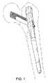
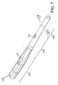
本発明の実施形態による方法、装置、及びシステムは、大腿骨骨折治療の改善を追求するものである。図1〜図6は、本発明による髄内釘100の一実施形態の様々な説明図である。髄内釘100は、骨内部への挿入を助けるための貫通した長手ボア130を有する。髄内釘100は、近位区間102、移行区間104、及び遠位区間106を有する。 Methods, devices and systems according to embodiments of the present invention seek to improve femoral fracture treatment. 1-6 are various illustrations of one embodiment of an
図1〜図6に示す特定の構造における近位区間102は、好ましくは、典型的な骨皮質により精密に対応する解剖学的にもたらされた形状を特徴とする。このような形状の一種類を、近位区間102の断面図として図6に示す。図6に示す近位区間102の特定の断面図はその長さの少なくともいくつかの部分に沿って全体的に非円形であり、内側面または側面109よりも大きい外側面または側面108を有する。外側面108及び内側面109は、第1の面110及び第2の面116によって結合されている。第1の面110と外側面108の交差部は、第1の丸まったコーナー112であり、第2の面116と外側面108の交差部は、第2の丸まったコーナー114である。第1の面110、第2の面116、及び外側面108は、ほぼ長さが等しい。 第1の面110及び第2の面116は、内側面109が外側面108よりも短くなるように、外側面108に対して鋭角に向けられる。外側面108を内側面109より長くすることで髄内釘100の回転に対する安定性が増し、曲げ及びひねりに対する耐性も向上する。 The
図6に示す内側面109には、丸みを付けることができる。図4から分かるように、丸まった内側面109は移行区間104から突出し、髄内釘100の近位端へと続く。内側面109の突出部は大腿骨の距領域に対応しており、骨と髄内釘100との間での荷重分配の均等性を向上させる。更に、近位区間の全体的な断面形状により、近位区間内のピーク応力が低減される。より具体的には、髄内釘及びスクリューアセンブリの組合せにおける典型的な破損の形は、釘がその外側面にかかる張力により破損することである。この張力は、スクリューアセンブリにかかる体重荷重による曲げモーメントによって発生する。従って、釘の張力がかかる側面である外側面上により多くの材料を含み、外側領域または両方の強度及び剛度を高めるように断面をより効果的に形状付けることが、釘の近位区間内の応力を低減させるのに有利となり得る。図6に示した設計は、この目的を達成する。外側面108は、内側面109より幅が広く、従って、少なくとも部分的にフランジのような効果を与える。外側面108上の材料に発生する単位面積あたりの応力は、外側面が内側面109のようなより小さい断面領域を特徴とする場合よりも小さい。 The
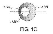
同じ原理による利益を受ける本発明の別の一実施形態による構造を、図1B及び図1Cに示す。図1B及び図1Cは断面がほぼ円形の髄内釘1100を示し、そのほぼ円形の開口1128が断面の円周の中心から外して配置されている。これら2つの図に示す特定の構造では、偏心開口1128は、外側面1108側で、材料のより大きい部分が荷重を受け応力を低減させることができるように、内側面1109に向かってずれている。同様に、断面の外側面側により多くの材料を提供するいかなる断面も、釘内部のその面側の単位面積あたりの応力を低減させる。 A structure according to another embodiment of the invention that benefits from the same principles is shown in FIGS. 1B and 1C. FIGS. 1B and 1C show an
近位部分102の断面における外側部分のいくつかの部分に材料または質量を付け足すことができる特定の方法とは関係なく、外側部分または両側の強度及び剛度を増大させるために、断面のいくつかの部分に材料を加えたり除去したりすることができ、この作用は、外側面または側面108の方向に少なくとも部分的に向けられた断面に慣性モーメントを与えることを特徴とすることができる。好ましい実施形態では、慣性モーメント(図6の文字Mで示される)は外側方向に延び、あるいは、外側面108の接線T1との交点l1から、内側面109の接線T2との交点l2へと延びる線Lの中点である点Pから、少なくとも部分的に外側面または面108に向かって延びることを特徴とすることができる。言い換えると、少なくともいくつかの場合における作用は、慣性モーメントが断面の中心から少なくとも部分的に外側方向に延びることを特徴とする断面を形成することである。好ましくは、その中心は、断面の外側縁部と内側縁部の中点とすることができる。あるいは、その中心は、断面の質量の中心とすることができる。中心からの増分質量の距離の平方の関数である慣性モーメントにより生じる回転半径は、近位部分102の外側部分における、断面内のより多くの質量またはより戦略的に配置された質量により生じる更なる強度を反映している。いくつかの構造で線Lは、横断開口の軸と同一平面上にあり、かつ断面と同一平面上にあり、従ってこれらの平面の交線によって規定される。一方で図1Aが、他方で図1B及び図1Cが示すように、これらは、このように外側に更なる強度及び剛度を付与することができる数多くの構造のうちのわずか2つであり、断面はその軸の少なくとも1つに対して非対称とすることができるがそうする必要はないことに留意されたい。更に、長手開口130は、その中心軸をその断面と共有するように配置することができ、あるいは、外側に強度を与えるのを助けるため、またはその他の目的のためにずらすことができる。 In order to increase the strength and stiffness of the outer part or both sides, regardless of the particular way in which material or mass can be added to some part of the outer part in the cross section of the
図1〜図6に示す特定の装置では、第1の面110、第2の面116、及び外側面108は平坦である。あるいは、これらの面に丸みを付けたり、それ以外の形で非平坦にすることができる。図1〜図6示す実施形態では内側面109に丸みが付けられているが、当業者であれば理解できるように、内側面を平坦にすることもできる。 In the particular apparatus shown in FIGS. 1-6, the
近位区間102は、髄内釘100を貫通する締結またはスクリューアセンブリ200(その様々な種類を図19〜図41に示す)を受ける、横断開口118を有する。図1〜図4に示す近位横断開口118の一実施形態は、2つの重なり合う円形開口120、122で形成されており、近位円形開口120の直径は遠位円形開口122よりも小さい。図示した近位円形開口120は、以下でより詳細に説明するように、スクリューアセンブリを挿入する深さを制約するための肩132を有する。当分野の技術者には知られているように、様々なスクリューアセンブリの挿入を可能にするその他様々な開口を使用することができる。たとえば、図33は円形開口を有する髄内釘を示す。 図33の実施形態は、以下でより詳細に説明する。 The
図3に示す近位区間102は、近位端開口128を有する。近位端開口128は、スクリューアセンブリの回転及び摺動位置を固定するために使用することができる固定スクリューの挿入が可能になるように、ねじ切りされている。固定スクリューはまた、ラグスクリュー202の回転または摺動を独立に制限するために、コンプレッションスクリュー204(図19)をまたぎ、ラグスクリュー202(図19)とぶつかり合うための機構を備える。 The
図1〜図6に示すように、移行区画104は、近位区間102から遠位区間106へとテーパ形状になっている。移行区画104はテーパ形状とされて髄管内に圧入され、これより沈降が制御される。テーパ形状の移行区間104は、釘100が意図されている以上に大腿骨の髄管内へと押し下げられないようにすることを助ける。 As shown in FIGS. 1-6, the
図1〜図6に示す髄内釘100の実施形態では、移行区間104の断面は円形であるが、当分野の技術者に知られているように、断面を変えることができる。断面は、近位区間102の断面と同様に、解剖学的に由来し、楕円形または非円形とすることができる。図1〜図6に示す実施形態では、移行区間104は遠位横断開口124を有する。遠位開口124は、髄内釘100を係止するための遠位係止スクリューを、髄内釘100を貫通して挿入することを可能にする。 In the embodiment of the
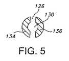
髄内釘100の遠位区間106は、全体的に円筒状であり、曲げ剛度が低減されるように構成されている。図1〜図5に示す実施形態は、遠位区間106の中心を貫通し、2つの側部134、136を形成する長手スロット126を有する。スロットは、髄内釘100の遠位端での曲げ剛度を低減させ、人工的な周辺骨折の可能性を低減させる。 The
図1Dは、本発明の別の一実施形態による髄内釘100を示す。この釘は、その近位部分での、外側−内側軸について対称な非円形断面(この例では楕円形断面が好ましいが必須ではない)を特徴とし、中心合わせされた長手ボア(この例では円形断面が好ましいが必須ではない)を特徴とする。この釘は、髄管内でのねじりに対抗できる程度の追加の安定性を達成する。この釘はまた、近位断面の外側縁部または側面へとより多くの質量を配置する目的を達成する。この釘は更に、内側縁部または側部へと更なる質量を配置し、従って、荷重がかけられると外側縁部または側面に引張応力を与える構成要素である締結アセンブリのメカニカルアドバンテージを低減させるための支点として働く、更なる構造を提供する。 FIG. 1D shows an
図7〜図18は、本発明のその他の実施形態による髄内釘100を示す。図7及び図13は、長手ボアを全くもたない髄内釘100を示す。 7-18 illustrate an
図8及び図14は、移行区間104及び遠位区間106に剛度低減スロット140を有する、髄内釘100を示す。剛度低減スロット140は、髄内釘100の遠位端の曲げ剛度を低減させ、いくつかの実施形態では、係止スクリューを受けるために使用することができる。 FIGS. 8 and 14 show an
図9及び図15は、遠位区間106及び移行区間104の一部にクローバ形のパターンを形成する3つの長手スロット138を有する、髄内釘100を示す。このパターンは髄内釘100付近の血液の流れをより容易にし、また釘100の遠位端の曲げ剛度を低減させる。 FIGS. 9 and 15 show an
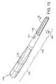
図10及び図16は、遠位区間106及び移行区間104の一部が一連の長手溝146を有する髄内釘100を示す。長手溝146は、遠位端の曲げ剛度を低減させ、回転に対する抵抗をもたらし、髄内釘100付近の血流を促進する。 FIGS. 10 and 16 show an
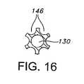
図11及び図17は、移行区間104及び遠位区間106がフィン144を有する髄内釘100を示す。フィン144は、回転に対する抵抗を髄内釘100にもたらす。 FIGS. 11 and 17 show an
図12及び図18は、遠位区間106及び移行区間104の一部に配置された逆とげ(barb)142を有する髄内釘100を示す。逆とげ142は、回転に対する抵抗を髄内釘100にもたらす。 FIGS. 12 and 18 show an
本発明による髄内釘は、いかなる適当な知られた技術によって患者に挿入してもよい。一般に、骨の髄管は、釘を挿入するための空洞を形成するための適切な道具で下準備されている。空洞のいくつかの部分は、釘を挿入した後に血流のための十分な空間が可能になるように、釘の外周よりも約1mm大きく形成される。案内ピンまたはワイヤは、下準備された髄管内に選択的に挿入される。次いで、釘が所望の位置へと案内される。釘が管状になっている場合は、案内ワイヤ上で釘を案内することができる。釘の位置は、イメージ増倍(intensification)によって確かめることができる。 The intramedullary nail according to the present invention may be inserted into the patient by any suitable known technique. Generally, the medullary canal of the bone is prepared with a suitable tool for forming a cavity for inserting a nail. Some portions of the cavity are formed approximately 1 mm larger than the outer periphery of the nail so that there is sufficient space for blood flow after the nail is inserted. A guide pin or wire is selectively inserted into the prepared medullary canal. The nail is then guided to the desired position. If the nail is tubular, it can be guided over the guide wire. The position of the nail can be confirmed by image intensification.
図19は、髄管を下準備するための道具300の一実施形態を示す。この道具は、穴ぐり用のドリルビット302、及びほぞ穴チゼル304を有する。動作時は、ドリルビット302は大腿骨の髄管を穴ぐりし、ほぞ穴チゼル304は骨のより近位の端部でより大きい断面を切削する。 図19に示すように、ほぞ穴チゼル304は、髄内釘の近位区間とほぼ同形状の、解剖学的に由来する断面を有する。このようなタイプの形状のほぞ穴チゼルを適用することにより、最小限しか変更されていない骨皮質に釘の近位端を載せることがより容易になる。ほぞ穴チゼル304は、複雑で非対称な形状であっても、多種多様の形状とすることができる。これによって、円形の空洞を更に孔ぐりせずに、多種多様な形状の髄内釘を受け入れることができる空洞を形成するための装置及び方法が可能になるので有利である。正確に共形な空洞を形成することは、健康な骨を不必要に除去することを防ぎ、釘を安定して載せることを保証する上で有益である。 FIG. 19 shows one embodiment of a
動作時は、図示した実施形態の道具300は、ドリルビット302が孔ぐりし、ほぞ穴チゼル304が同時に切削を行う、1つのユニットとして前進させられる。ドリルビット302は、電力駆動または手動で回転させることができる。同様に、道具300全体も、手動で髄管内へと前進させ、あるいはメカニカルアドバンテージまたは電動機器の助けにより前進させることができる。その他の構成では、道具300全体が、髄管内に挿入された案内ワイヤ上で動作可能となりそれによって案内されるように、ドリルビット302を管状にすることができる(図示せず)。 In operation, the
他の実施形態では、孔ぐりのためのビットは、ほぞ穴チゼル304などの切削道具とは別になっているより従来的なリーマである。このような例で空洞を形成するための方法は、まず、従来的なリーマで開口を孔ぐりすることを含む。次いで、空洞を形成するために、埋め込まれる髄内釘と同様の形状のチゼルまたはブローチなどの装置を使用する。チゼルまたはブローチは、手動で、ハンマまたはマレットの助けにより、または他の電動機器を使用して、押し込むことができる。次に、形成された空洞と一致する釘が埋め込まれる。 In other embodiments, the bit for drilling is a more conventional reamer that is separate from the cutting tool, such as the
総形ブローチ、または特注のルータビット及びテンプレートなど、他の特注器具も同様に使用することができる。 ブローチは大腿骨ステムに開口を形成するために長く使用されており、ブローチの使用は当分野の技術者によく知られている。ルータビット及びテンプレートは、骨に所望の形状を削り出すために効果的に使用することができる。所望の空洞を形成するために、このような方法を孔ぐりまたはブローチ削りと組み合わせて使用することもできる。 Other custom instruments can be used as well, such as full broaches or custom router bits and templates. Broaches have long been used to create openings in the femoral stem, and the use of broaches is well known to those skilled in the art. Router bits and templates can be used effectively to cut out the desired shape in the bone. Such methods can also be used in combination with drilling or broaching to form the desired cavity.
本発明の髄内釘は、数ある長骨の骨折の中でも、近位大腿骨骨折及び大腿骨骨幹骨折を治療するために使用することができる。大腿骨骨幹骨折の治療に使用される場合、髄内釘は、1つまたは複数の締結装置で大腿骨内に固定される。近位大腿骨骨折の治療に使用される場合、髄内釘は、好ましくは近位スクリューアセンブリと共に使用される。 The intramedullary nail of the present invention can be used to treat proximal femoral fractures and femoral shaft fractures, among other long bone fractures. When used to treat a femoral shaft fracture, the intramedullary nail is secured within the femur with one or more fastening devices. When used to treat a proximal femoral fracture, an intramedullary nail is preferably used with a proximal screw assembly.
図20及び図21は、本発明の一実施形態による締結アセンブリ200と共に使用される、本発明の一実施形態による髄内釘100を示す。このタイプの締結アセンブリは、その他様々な骨で、他の様々な兆候を治療するために使用することができるが、例示目的で、ここでは近位大腿骨での使用を説明する。一般に、スクリューアセンブリは、1つの骨片が制御されたやり方で別の骨片から引き戻されるまたは押し離される、いかなる状況でも有用である。締結アセンブリは、骨片の移動が達成された後にアセンブリを所望の方向に摺動させることができるように構成可能であるという、更なる利点を提供する。 20 and 21 illustrate an
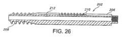
図21に示すように、髄内釘100内の近位横断開口118の軸は、近位区間102に対してある角度をなしており、使用時は、大腿骨骨頭に向かって方向付けられる。この実施形態の締結アセンブリ200では、ラグスクリュー202などの係合部材が、コンプレッションスクリュー204または圧迫ペグなどの圧迫装置と共に使用される。スクリューは、コンプレッションスクリュー204が部分的にラグスクリュー202の周縁内に入り込むよう、使用時にラグスクリュー202の周縁がコンプレッションスクリュー204の周縁と部分的に交わるように構成される。ラグスクリュー202とコンプレッションスクリュー204のこの特定の組合せを更に、図22から図32に示す。簡潔に述べると、これらの図に示すラグスクリュー202は、大腿骨骨頭に係合し、髄内釘100の横断開口118内で摺動することが意図されている。ラグスクリュー202の釘100に対する摺動、従って骨折部位に対する大腿骨骨頭の圧迫力がコンプレッションスクリュー204の回転によって制御されるように、コンプレッションスクリュー204は、釘100の横断開口118内の肩またはその他の構造と係合し、またコンプレッションスクリュー204が入り込むラグスクリュー202の部分にねじ係合する。 As shown in FIG. 21, the axis of the proximal
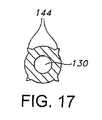
これらの図に示すラグスクリュー202は、細長い本体206及びねじ切り端部208を備える。図24及び図25に示すように、ねじ切り端部208は鋭利な端部を備えず、これは大腿骨骨頭を切断する可能性を低減させる。細長い本体206は、コンプレッションスクリュー204を部分的にラグスクリュー202の周縁内に配置することを可能にする溝212を備える。溝212は、コンプレッションスクリュー204のねじ切り区間214と補対し協働する、ねじ切り部210を備える。コンプレッションスクリュー204は、ねじ切り区間214及び頭部区間215を備える。コンプレッションスクリュー204のねじ切り区間214は、ねじ山が開口内で容易に摺動し、また切断の可能性を低減させることができるよう、ねじ山の外面が比較的平坦かつ滑らかになるように構成される。 The
ラグスクリュー202は、破損部を横断し大腿骨骨頭内へと延びるように、近位横断開口118内及び大腿骨に予め穿孔された穴内部で受けられる。ラグスクリュー202を開口118内で回転させてそのねじ切り端部208を大腿骨骨頭に係合させるにつれて、ラグスクリュー202のねじ切り端部208は、大腿骨骨頭に係合する。ねじ切り端部208は、大腿骨内にひっかかりを得るためのいかなる装置とすることもでき、これらに限定されないが、螺旋、逆とげ、ブレード、フック、伸縮装置などを含めていかなる所望の構成のねじ山を備えることもできる。ラグスクリュー202を大腿骨骨頭内に配置する深さは骨折部の所望の圧迫力によって異なる。 The
コンプレッションスクリュー204はまた、近位横断開口118を通して、大腿骨骨頭内の予め穿孔された穴内で受けることができる。コンプレッションスクリュー204のねじ切り区間214は、ラグスクリュー202の溝212のねじ切り部と係合する。近位横断開口118は、コンプレッションスクリュー204がほぼ内側方向に摺動する、従って開口118を通ってラグスクリュー202が摺動するのを制限するための、内部肩132(図21)を有する。コンプレッションスクリュー204が締められると、コンプレッションスクリューのねじ山214はラグスクリュー溝のねじ切り部210に係合し、コンプレッションスクリュー204はラグスクリュー202の下でほぼ内側方向に移動する。コンプレッションスクリュー204の頭部区間215は、近位横断開口118の肩132に係合し、コンプレッションスクリュー204がほぼ内側方向に更に移動するのを妨げる。コンプレッションスクリュー204が締められるにつれて、ラグスクリュー202は、髄内釘に向かってほぼ外側方向に引っ張られ、骨折部に圧迫力をもたらす。ラグスクリュー202の周縁と部分的に交わるコンプレッションスクリュー204は、より大きい表面抵抗をもたらし、大腿骨骨頭が回転することを妨げるのを助ける。従ってコンプレッションスクリュー204は、骨折した骨の骨片を互いに移動させる機構の一部として働くだけでなく、大腿骨骨頭の骨と直接接触して、大腿骨骨頭がラグスクリュー202の軸の周りで回転することを妨げるのを助ける。 The
一実施形態では、コンプレッションスクリュー204を係合し、コンプレッションスクリュー204及びラグスクリュー202を定位置に固定するために、髄内釘の近位端開口128内に配置される固定スクリュー(図示せず)が使用される。締結アセンブリ200を定位置に固定するための固定スクリューが、骨折部のパターンに応じて使用される。締結アセンブリを係合するために固定スクリューが使用されない場合、締結アセンブリ200は、肩132で制限される近位開口内で摺動することができる。 In one embodiment, a locking screw (not shown) disposed within the proximal end opening 128 of the intramedullary nail to engage the
図20〜図32に示すラグスクリュー及びコンプレッションスクリューの実施形態では、コンプレッションスクリュー204の直径はラグスクリュー202の直径より小さい。ラグスクリューとコンプレッションスクリューの直径は同じにすることができ、あるいは、ラグスクリューの直径をコンプレッションスクリューの直径より小さくすることができる。ラグスクリュー及びコンプレッションスクリューのねじ山は、当分野の技術者に知られているように、様々な異なる形状とすることができる。一般に、ラグスクリューの目的は、骨内部にひっかかりを得ることであり、コンプレッションスクリューの目的は、ラグスクリューと係合し、それを引っ張るまたは移動させることである。こうした機能を可能にするいかなる構成も、本発明の範囲内にある。 In the lag screw and compression screw embodiments shown in FIGS. 20-32, the diameter of the
締結アセンブリは更に、人工大腿骨骨頭(prosthetic femoral head)及び頚部の付加が可能になるように構成することができる。そのような実施形態では、ラグスクリュー202が、人工頭骨及び頚部で置き換えられる。頚部は、釘100内の近位横断開口118内に嵌り込む。この設計は、修復された大腿骨骨折部及び股関節が変性または再び損傷し、後に人工股関節全置換術(THA:total hip arthroplasty)が必要となる場合に有利である。THAの遂行決定は、術中に、または少し期間をおいて行うことができる。THAに関して知られているように、股関節ステムを受け入れるために大腿骨を下準備しなければならない代わりに、締結アセンブリ200と共に、骨のほんのわずかな部分を取り出す必要があるだけである。次いで、人工頭骨及び頚部が近位横断開口118内に挿入され、寛骨臼(acetabulum)が準備され、残りのTHAが完了される。 The fastening assembly can be further configured to allow for the addition of a prosthetic femoral head and neck. In such embodiments,
図33は、本発明の別の一実施形態による、代替締結アセンブリ400を備える髄内釘100の断面図である。図示した締結アセンブリは、参照により本明細書に組み込む特許文献1、及び様々な関連国際特許でより詳しく開示されているような、スミスアンドネフュー社のIMHS(登録商標)システムの圧迫締結アセンブリに非常に類似している。図示した装置の改善点は、この装置が、上記のような解剖学的に由来する形状及びその複数の利点を有する髄内釘100を備えることである。動作時は、スリーブ401は髄内釘100を貫通して嵌り、固定スクリューまたはその他の効果的な機構によって釘に固定することができる。摺動ラグスクリュー402は、スリーブ401内で軸方向に動くことができる。コンプレッションスクリュー404は、コンプレッションスクリュー404を締めると摺動ラグスクリュー402がスリーブ401内に引き戻されるように、摺動ラグスクリュー402内にねじ込まれる。この機構を用いると、骨片が所望の位置に置かれるが、位置決めされてからも摺動圧迫力をもたらすことができる。 FIG. 33 is a cross-sectional view of an
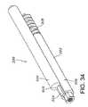
図34〜図35は、本発明の別の一実施形態による、ラグスクリュー202及び圧迫ペグ502を有する締結アセンブリ200を示す。図34に示すように、ラグスクリュー202及び圧迫ペグ502は、使用時にラグスクリュー202の周縁が部分的に圧迫ペグ502の周縁と交わるように構成されるが、いくつかの実施形態では、周縁が交わるのではなく隣接するように構成される。ラグスクリュー202は、細長い本体206及びねじ切り端部208を備える。ラグスクリュー202は、溝212上にキー504を有する。圧迫ペグ502は、ラグスクリュー202のキー504を受けるように構成されたスロット503を有する。キー504及びスロット503は、断面を考えたときに、三角形、D字形、鍵穴形、及び当分野の技術者に自明のその他の形状など、様々な相補的な形状とすることができる。動作時は、圧迫ペグ502とラグスクリュー202との間、またはアセンブリ全体と髄内釘100との間で異なる力を加える圧迫用の道具(図示せず)により、圧迫ペグ502を、ラグスクリュー202に対して相対的に移動させることができる。 34-35 illustrate a
図34〜図35に示す締結アセンブリ200では、ラグスクリュー202は、破損部を横断し大腿骨骨頭内へと延びるよう、髄内釘の近位開口内で摺動するように受けられる。ラグスクリュー202のねじ切り端部208は、大腿骨骨頭に係合する。ラグスクリュー202が大腿骨骨頭に適切に係合された後、圧迫ペグ502のスロット503がラグスクリュー202のキー504を受けるときラグスクリュー202が更に回転するのを防ぐために、圧迫ペグ502が近位開口内で大腿骨骨頭内の予め穿孔された穴へと挿入される。より大きい抵抗面積を提供することにより、圧迫ペグ502は、大腿骨骨頭がラグスクリュー202上で回転することを妨げるのを助ける。圧迫力502は、釘の近位端開口内に配置される固定スクリューにより、髄内釘100内の定位置に固定される。ラグスクリュー202は、近位開口を通って圧迫ペグ502上で摺動することができる。別の実施形態では、圧迫ペグ502はその表面上に逆とげを有する。 In the
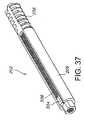
本発明の別の一実施形態による締結アセンブリ200を、図36〜図37に示す。この実施形態の締結アセンブリ200は、ラグスクリュー202のキー504及び圧迫ペグ502のスロット503が相補的なラチェット歯506を有すること以外は図34〜図35に示す実施形態と同様な、圧迫ペグ502及びラグスクリュー202を有する。圧迫ペグ502は、近位端開口内に配置される固定スクリューによって髄内釘内の定位置に固定される。ラグスクリューをほぼ外側方向に引っ張ることによって、骨折部の圧迫が達成される。ラチェット歯506は、ラグスクリュー202がほぼ外側方向に移動することを可能にするが、ラグスクリュー202がほぼ内側方向に移動することを妨げる。移動を実現するために、図34〜図35に関して説明した道具と類似の圧迫用道具を使用することができる。 A
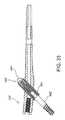
図38〜図39は、本発明の別の一実施形態による、ラグスクリュー602、十字線スクリュー610及びコンプレッションスクリュー604を有する締結アセンブリ200を示す。ラグスクリュー602は、細長の本体606及びねじ切り端部608を備える。細長の本体606は、断面が半円形である。スクリュー602、604、610は、ラグスクリュー602の周縁が、十字線スクリュー610及びコンプレッションスクリュー604の周縁と交わるように構成される。ラグスクリュー602の細長の本体606は、十字線スクリュー610のねじ切り区間602と補対及び協働するようにねじ切りされている。十字線スクリュー610は、ラグスクリュー602及びコンプレッションスクリュー604と係合するようにねじ切りされている。コンプレッションスクリュー604は、ねじ切り部614及び頭部612を備える。 38-39 illustrate a
この実施形態では、ラグスクリュー602、十字線スクリュー610、及びコンプレッションスクリュー604は、髄内スクリューの近位開口内で摺動するように同時に受けられる。ラグスクリュー602は、骨折部を横断し大腿骨骨頭へと延びる。ラグスクリュー602のねじ切り端部608は、大腿骨骨頭に係合する。コンプレッションスクリュー604が締められるとき、コンプレッションスクリューのねじ山614が、十字線スクリュー610及びラグスクリュー602のねじ山に係合し、それによってラグスクリュー602をほぼ外側方向に髄内釘へと移動させ、大腿骨骨頭に圧迫力をもたらす。次いで、十字線スクリュー610が回転され、コンプレッションスクリュー604を遠位方向にラグスクリュー602から離して移動させる。代替として締結アセンブリ200を、コンプレッションスクリュー604がラグスクリュー602に対して近位に移動するように構成することができる。ラグスクリュー602から離れたコンプレッションスクリュー604は、より大きい抵抗面積を加えることにより、大腿骨骨頭がラグスクリュー602上で回転しないようにするのを助ける。 In this embodiment, the
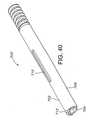
図40〜図41は、本発明の別の一実施形態による、ラグスクリュー702及び圧迫ペグ704を有する締結アセンブリ200を示す。ラグスクリュー702は、細長い本体706及びねじ切り端部708を備える。細長い本体706は、大腿骨に挿入するためのラグスクリュー702の周縁内に圧迫ペグ704を部分的に位置決めすることを可能にするために半円形となっており、また細長い本体706の内面上に配置されたキー712を有する。細長い本体706はまた、本体を貫通する開口710を有する。圧迫ペグ704は全体的に円筒形であり、ラグスクリューの半円形本体706内に嵌るようにサイズ決めされている。ラグスクリューのキー712は、圧迫ペグ704内のスロット714によって受けられる。キー712及びスロット714は、相補的なラチェット歯を備える。 40-41 illustrate a
この実施形態では、ラグスクリュー702及び圧迫ペグ704は、髄内スクリューの近位開口で、大腿骨内に予め穿孔された穴内へと摺動するように同時に受けられる。ラグスクリュー702は、破損部を横断し大腿骨骨頭内へと延びる。ラグスクリュー702のねじ切り端部は、大腿骨骨頭に係合する。圧迫ペグ704とラグスクリュー702との間、またはアセンブリ全体と髄内釘100との間での移動を実現するために、図34〜図35に関連して説明した道具と同様の圧迫用道具を使用することができる。締結アセンブリの位置を固定するために、固定スクリューを使用することができる。固定スクリューは、それが締められると固定スクリュー上の突出部がラグスクリュー702のスロット710で受けられ、コンプレッションスクリュー704をラグスクリュー702から離して移動させるように構成される。ラグスクリュー702から離れたコンプレッションスクリュー704は、より大きい抵抗面積を加えることにより、ラグスクリュー上で大腿骨骨頭が回転することを妨げるのを助ける。 In this embodiment,
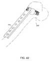
図42は、締結アセンブリ200が圧迫プレート150と協働して使用される、本発明の別の一実施形態を示す。図示のとおり、装置は大腿骨に適用されている。上記締結アセンブリ200の様々な実施形態を同様の圧迫プレートと共に使用することができ、様々な圧迫プレートは、解剖学的なその他の部位に適用可能となるように構成することができる。 FIG. 42 illustrates another embodiment of the present invention in which the
図43は、締結アセンブリ200が関節周囲プレート170と共に使用される、本発明の別の一実施形態を示す。図示したプレート及び締結アセンブリは、近位脛骨に適用されている。上記締結アセンブリ200の様々な実施形態は、同様の関節周囲プレートと共に使用することができ、様々な関節周囲プレートは、解剖学的なその他の部位に適用可能となるように構成することができる。 FIG. 43 illustrates another embodiment of the present invention in which the
図44は、締結アセンブリ200が上腕骨用の釘190と組み合わせて使用される本発明の別の一実施形態を示す。図示のとおり、コンプレッションスクリュー204の頭部区間212は上腕骨に支えられて、上腕骨に対する圧迫力を生じる。ラグスクリュー202に圧迫力が加わり、ラグスクリュー202がそのねじ切り端部208によって骨片に固定された状態で、骨片を適切な治療のための位置へと引っ張ることができる。場合によっては、頭部区間212と、それにより圧迫力が加えられる上腕骨との間に、座金または座面(図示せず)を置くことが有利なことがある。 更に別の変形形態では、頭部区間212が上腕骨に貫入し上腕骨用の釘190の一部で支えられることが可能になるように、上腕骨内の開口を広げることができる。そのような実施形態では、圧迫アセンブリ200は、ねじ切り端部208により骨の同じ領域内でひっかかりを得るために、図44に示すよりも短くなる。上記締結アセンブリ200の様々な実施形態は、同様の釘と共に使用することができ、様々な釘は、解剖学的な他の部位に適用可能となるように構成することができる。 FIG. 44 illustrates another embodiment of the present invention in which the
当分野の技術者には理解されるように、以上で説明及び図示した本発明の特定の実施形態は、本発明を説明するために提供されたものであり、説明した実施形態の構造及び材料には、以上で説明され添付の特許請求の範囲に含まれる本発明の精神及び範囲から逸脱することなく様々な変更を加えることができる。 As will be appreciated by those skilled in the art, the specific embodiments of the present invention described and illustrated above are provided to illustrate the present invention, and the structures and materials of the described embodiments. Various changes may be made without departing from the spirit and scope of the invention as described above and included in the scope of the appended claims.
100 髄内釘
102 近位区間
104 移行区間
106 遠位区間
108 外側面
109 内側面
118 横断開口
120 円形開口
122 円形開口
124 遠位開口
126 スロット
128 近位端開口
132 肩
142 逆とげ
144 フィン
146 長手溝
150 圧迫プレート
170 関節周囲プレート
200 締結アセンブリ
202 ラグスクリュー
204 コンプレッションスクリュー
206 本体
208 ねじ切り端部
210 ねじ切り部
212 溝
214 ねじ切り区間
215 頭部区間
300 道具
302 ドリルビット
304 ほぞ穴チゼル
400 代替締結アセンブリ
401 スリーブ
402 ラグスクリュー
404 コンプレッションスクリュー
502 圧迫ペグ
503 スロット
504 キー
506 ラチェット歯
602 ラグスクリュー
604 コンプレッションスクリュー
606 本体
608 ねじ切り端部
610 十字線スクリュー
612 頭部
614 ねじ切り部
702 ラグスクリュー
704 圧迫ペグ
706 本体
708 ねじ切り端部
710 開口
712 キー
714 スロット100
Claims (8)
Translated fromJapaneseb.前記遠位区間と近位区間との間に形状付けられた結合部を形成する移行区間と、
を備え、
c.前記近位区間が、
1.骨に係合するように為された構造を受けるように為された横断開口と、
2.外側側面と、
3.内側側面と、
4.装置の長さ方向に対してほぼ直角に向いた少なくとも1つの断面と、
を備え、前記断面が、前記外側側面の接線との交点から前記内側側面の接線との交点へと前記断面内で延びる線の中点から、外側側面に向かって、次第に幅が広くなるように形成されている、又は、より多くの質量を備えるように形成されていることを特徴とする骨折部を治療するための装置。a. An elongated distal section adapted to be inserted into the medullary canal of the bone;
b. A transition section that forms a shaped joint between the distal section and the proximal section;
With
c. The proximal section is
1. A transverse opening adapted to receive a structure adapted to engage the bone;
2. The outer side,
3. The inner side,
4). At least one cross section oriented substantially perpendicular to the longitudinal direction of the device;
The cross sectiongradually increases in width from the midpoint of the line extending in the cross section from the intersection point with the tangent line of the outer side surface toward the outer side surface from the intersection point with the tangent line of the inner side surface. A device for treating a fractured part, characterizedin that it is formed or formed to have more mass .
d.係合部材及び圧迫部材を有する締結アセンブリであって、前記締結アセンブリが前記横断開口内で摺動するように為される、締結アセンブリと、
e.前記係合部材が第2の骨部分に係合するように為され、かつ前記係合部材及び前記圧迫部材は、前記圧迫部材が前記装置の一部及び前記係合部材の一部と相互作用して前記第1の骨部分と前記第2の骨部分との間の動きを制御することが可能になるように構成されることと、
f.埋め込まれたときに前記圧迫部材が第2の骨部分と接触することと、
を、さらに備えることを特徴とする請求項1に記載の装置。The device is adapted to be at least partially implanted in a first bone portion;
d. A fastening assembly having an engagement member and a compression member, wherein the fastening assembly is adapted to slide within the transverse opening;
e. The engagement member is adapted to engage a second bone portion, and the engagement member and the compression member interact with the compression member with a portion of the device and a portion of the engagement member. And being configured to be able to control movement between the first bone portion and the second bone portion;
f. The compression member contacts the second bone portion when implanted;
The apparatus according to claim 1, further comprising:
Applications Claiming Priority (2)
| Application Number | Priority Date | Filing Date | Title |
|---|---|---|---|
| US10/658,351US20050055024A1 (en) | 2003-09-08 | 2003-09-08 | Orthopaedic implant and screw assembly |
| US10/658,351 | 2003-09-08 |
Related Parent Applications (1)
| Application Number | Title | Priority Date | Filing Date |
|---|---|---|---|
| JP2006525532ADivisionJP4654186B2 (en) | 2003-09-08 | 2004-09-08 | Orthopedic implant and bone screw assembly |
Related Child Applications (1)
| Application Number | Title | Priority Date | Filing Date |
|---|---|---|---|
| JP2013122604ADivisionJP5744968B2 (en) | 2003-09-08 | 2013-06-11 | Orthopedic implant and bone screw assembly |
Publications (2)
| Publication Number | Publication Date |
|---|---|
| JP2011036716A JP2011036716A (en) | 2011-02-24 |
| JP5485855B2true JP5485855B2 (en) | 2014-05-07 |
Family
ID=34226764
Family Applications (6)
| Application Number | Title | Priority Date | Filing Date |
|---|---|---|---|
| JP2006525532AExpired - LifetimeJP4654186B2 (en) | 2003-09-08 | 2004-09-08 | Orthopedic implant and bone screw assembly |
| JP2006525533AExpired - LifetimeJP4671963B2 (en) | 2003-09-08 | 2004-09-08 | Orthopedic plate and screw assembly |
| JP2010237596AExpired - LifetimeJP5485855B2 (en) | 2003-09-08 | 2010-10-22 | Orthopedic implant and bone screw assembly |
| JP2013122604AExpired - LifetimeJP5744968B2 (en) | 2003-09-08 | 2013-06-11 | Orthopedic implant and bone screw assembly |
| JP2014214902AExpired - LifetimeJP6549368B2 (en) | 2003-09-08 | 2014-10-21 | Orthopedic implant and bone screw assembly |
| JP2017177721APendingJP2017217513A (en) | 2003-09-08 | 2017-09-15 | Orthopedic Implant and Bone Screw Assembly |
Family Applications Before (2)
| Application Number | Title | Priority Date | Filing Date |
|---|---|---|---|
| JP2006525532AExpired - LifetimeJP4654186B2 (en) | 2003-09-08 | 2004-09-08 | Orthopedic implant and bone screw assembly |
| JP2006525533AExpired - LifetimeJP4671963B2 (en) | 2003-09-08 | 2004-09-08 | Orthopedic plate and screw assembly |
Family Applications After (3)
| Application Number | Title | Priority Date | Filing Date |
|---|---|---|---|
| JP2013122604AExpired - LifetimeJP5744968B2 (en) | 2003-09-08 | 2013-06-11 | Orthopedic implant and bone screw assembly |
| JP2014214902AExpired - LifetimeJP6549368B2 (en) | 2003-09-08 | 2014-10-21 | Orthopedic implant and bone screw assembly |
| JP2017177721APendingJP2017217513A (en) | 2003-09-08 | 2017-09-15 | Orthopedic Implant and Bone Screw Assembly |
Country Status (11)
| Country | Link |
|---|---|
| US (9) | US20050055024A1 (en) |
| EP (2) | EP1663037B1 (en) |
| JP (6) | JP4654186B2 (en) |
| AT (2) | ATE382300T1 (en) |
| AU (4) | AU2004272038B2 (en) |
| CA (2) | CA2536049C (en) |
| DE (2) | DE602004011083T2 (en) |
| DK (1) | DK1663037T3 (en) |
| ES (2) | ES2341962T3 (en) |
| PT (1) | PT1663037E (en) |
| WO (2) | WO2005025436A1 (en) |
Families Citing this family (256)
| Publication number | Priority date | Publication date | Assignee | Title |
|---|---|---|---|---|
| US6045551A (en) | 1998-02-06 | 2000-04-04 | Bonutti; Peter M. | Bone suture |
| US6368343B1 (en) | 2000-03-13 | 2002-04-09 | Peter M. Bonutti | Method of using ultrasonic vibration to secure body tissue |
| US6447516B1 (en) | 1999-08-09 | 2002-09-10 | Peter M. Bonutti | Method of securing tissue |
| US6635073B2 (en) | 2000-05-03 | 2003-10-21 | Peter M. Bonutti | Method of securing body tissue |
| US9138222B2 (en) | 2000-03-13 | 2015-09-22 | P Tech, Llc | Method and device for securing body tissue |
| US7094251B2 (en) | 2002-08-27 | 2006-08-22 | Marctec, Llc. | Apparatus and method for securing a suture |
| US7963966B2 (en) | 2000-06-06 | 2011-06-21 | Cole J Dean | Bone fixation system and method of use |
| US7447754B2 (en) | 2000-12-06 | 2008-11-04 | Microsoft Corporation | Methods and systems for processing multi-media editing projects |
| US20030055316A1 (en)* | 2001-09-19 | 2003-03-20 | Brannon James Kevin | Endoscopic bone debridement |
| US6719765B2 (en) | 2001-12-03 | 2004-04-13 | Bonutti 2003 Trust-A | Magnetic suturing system and method |
| US9155544B2 (en) | 2002-03-20 | 2015-10-13 | P Tech, Llc | Robotic systems and methods |
| US7179260B2 (en)* | 2003-09-29 | 2007-02-20 | Smith & Nephew, Inc. | Bone plates and bone plate assemblies |
| US7497864B2 (en) | 2003-04-30 | 2009-03-03 | Marctec, Llc. | Tissue fastener and methods for using same |
| US20050055024A1 (en)* | 2003-09-08 | 2005-03-10 | James Anthony H. | Orthopaedic implant and screw assembly |
| US7799030B2 (en)* | 2003-09-08 | 2010-09-21 | Smith & Nephew, Inc. | Orthopaedic plate and screw assembly |
| US7780667B2 (en)* | 2003-09-08 | 2010-08-24 | Smith & Nephew, Inc. | Orthopaedic plate and screw assembly |
| US20080039873A1 (en) | 2004-03-09 | 2008-02-14 | Marctec, Llc. | Method and device for securing body tissue |
| GB0406821D0 (en)* | 2004-03-25 | 2004-04-28 | Depuy Int Ltd | Reamer and method of reaming |
| DE602005023605D1 (en)* | 2004-05-21 | 2010-10-28 | Myers Surgical Solutions Llc | FRACTURE FIXATION AND STITIZATION STABILIZATION SYSTEM |
| US20060036248A1 (en)* | 2004-07-01 | 2006-02-16 | Ferrante Joseph M | Fixation elements |
| US20060015101A1 (en)* | 2004-07-15 | 2006-01-19 | Wright Medical Technology, Inc. | Intramedullary fixation assembly and devices and methods for installing the same |
| US9271766B2 (en) | 2004-10-26 | 2016-03-01 | P Tech, Llc | Devices and methods for stabilizing tissue and implants |
| US9463012B2 (en) | 2004-10-26 | 2016-10-11 | P Tech, Llc | Apparatus for guiding and positioning an implant |
| US9173647B2 (en) | 2004-10-26 | 2015-11-03 | P Tech, Llc | Tissue fixation system |
| US20060089646A1 (en) | 2004-10-26 | 2006-04-27 | Bonutti Peter M | Devices and methods for stabilizing tissue and implants |
| US9089323B2 (en) | 2005-02-22 | 2015-07-28 | P Tech, Llc | Device and method for securing body tissue |
| DE102005009347B8 (en)* | 2005-03-01 | 2008-11-20 | Gradl Medizintechnik Gmbh | Locking device for a broken or broken bone |
| US9060820B2 (en) | 2005-05-18 | 2015-06-23 | Sonoma Orthopedic Products, Inc. | Segmented intramedullary fracture fixation devices and methods |
| US8961516B2 (en)* | 2005-05-18 | 2015-02-24 | Sonoma Orthopedic Products, Inc. | Straight intramedullary fracture fixation devices and methods |
| AU2006282828B2 (en) | 2005-08-23 | 2013-01-31 | Smith & Nephew, Inc | Telemetric orthopaedic implant |
| US7955358B2 (en) | 2005-09-19 | 2011-06-07 | Albert Todd J | Bone screw apparatus, system and method |
| US20080249580A1 (en)* | 2005-09-28 | 2008-10-09 | Smith & Nephew, Inc. | Methods and Instruments of Reducing a Fracture |
| US20070123873A1 (en)* | 2005-10-31 | 2007-05-31 | Czartoski Timothy J | Intramedullary nail with oblique openings |
| US20070155271A1 (en)* | 2005-12-30 | 2007-07-05 | Touzov Igor V | Heat conductive textile and method producing thereof |
| US8641735B2 (en)* | 2006-01-27 | 2014-02-04 | Warsaw Orthopedic, Inc. | Implantable longitudinal orthopedic supports for accommodating multiple anatomical support requirements |
| US7967820B2 (en) | 2006-02-07 | 2011-06-28 | P Tech, Llc. | Methods and devices for trauma welding |
| US11278331B2 (en) | 2006-02-07 | 2022-03-22 | P Tech Llc | Method and devices for intracorporeal bonding of implants with thermal energy |
| US9439642B2 (en) | 2006-02-07 | 2016-09-13 | P Tech, Llc | Methods and devices for utilizing bondable materials |
| US8496657B2 (en) | 2006-02-07 | 2013-07-30 | P Tech, Llc. | Methods for utilizing vibratory energy to weld, stake and/or remove implants |
| US11253296B2 (en) | 2006-02-07 | 2022-02-22 | P Tech, Llc | Methods and devices for intracorporeal bonding of implants with thermal energy |
| US8070752B2 (en) | 2006-02-27 | 2011-12-06 | Biomet Manufacturing Corp. | Patient specific alignment guide and inter-operative adjustment |
| US9918740B2 (en) | 2006-02-27 | 2018-03-20 | Biomet Manufacturing, Llc | Backup surgical instrument system and method |
| US8133234B2 (en) | 2006-02-27 | 2012-03-13 | Biomet Manufacturing Corp. | Patient specific acetabular guide and method |
| US9289253B2 (en) | 2006-02-27 | 2016-03-22 | Biomet Manufacturing, Llc | Patient-specific shoulder guide |
| US7967868B2 (en) | 2007-04-17 | 2011-06-28 | Biomet Manufacturing Corp. | Patient-modified implant and associated method |
| US8282646B2 (en) | 2006-02-27 | 2012-10-09 | Biomet Manufacturing Corp. | Patient specific knee alignment guide and associated method |
| US8608748B2 (en) | 2006-02-27 | 2013-12-17 | Biomet Manufacturing, Llc | Patient specific guides |
| US8591516B2 (en) | 2006-02-27 | 2013-11-26 | Biomet Manufacturing, Llc | Patient-specific orthopedic instruments |
| US20150335438A1 (en) | 2006-02-27 | 2015-11-26 | Biomet Manufacturing, Llc. | Patient-specific augments |
| US8377066B2 (en) | 2006-02-27 | 2013-02-19 | Biomet Manufacturing Corp. | Patient-specific elbow guides and associated methods |
| US9339278B2 (en) | 2006-02-27 | 2016-05-17 | Biomet Manufacturing, Llc | Patient-specific acetabular guides and associated instruments |
| US8473305B2 (en) | 2007-04-17 | 2013-06-25 | Biomet Manufacturing Corp. | Method and apparatus for manufacturing an implant |
| US8298237B2 (en) | 2006-06-09 | 2012-10-30 | Biomet Manufacturing Corp. | Patient-specific alignment guide for multiple incisions |
| US9113971B2 (en) | 2006-02-27 | 2015-08-25 | Biomet Manufacturing, Llc | Femoral acetabular impingement guide |
| US8241293B2 (en) | 2006-02-27 | 2012-08-14 | Biomet Manufacturing Corp. | Patient specific high tibia osteotomy |
| US8407067B2 (en) | 2007-04-17 | 2013-03-26 | Biomet Manufacturing Corp. | Method and apparatus for manufacturing an implant |
| US8608749B2 (en) | 2006-02-27 | 2013-12-17 | Biomet Manufacturing, Llc | Patient-specific acetabular guides and associated instruments |
| US8092465B2 (en) | 2006-06-09 | 2012-01-10 | Biomet Manufacturing Corp. | Patient specific knee alignment guide and associated method |
| US8568487B2 (en) | 2006-02-27 | 2013-10-29 | Biomet Manufacturing, Llc | Patient-specific hip joint devices |
| US9907659B2 (en) | 2007-04-17 | 2018-03-06 | Biomet Manufacturing, Llc | Method and apparatus for manufacturing an implant |
| US8603180B2 (en) | 2006-02-27 | 2013-12-10 | Biomet Manufacturing, Llc | Patient-specific acetabular alignment guides |
| US8858561B2 (en) | 2006-06-09 | 2014-10-14 | Blomet Manufacturing, LLC | Patient-specific alignment guide |
| US8864769B2 (en) | 2006-02-27 | 2014-10-21 | Biomet Manufacturing, Llc | Alignment guides with patient-specific anchoring elements |
| US8535387B2 (en) | 2006-02-27 | 2013-09-17 | Biomet Manufacturing, Llc | Patient-specific tools and implants |
| US10278711B2 (en) | 2006-02-27 | 2019-05-07 | Biomet Manufacturing, Llc | Patient-specific femoral guide |
| US9173661B2 (en) | 2006-02-27 | 2015-11-03 | Biomet Manufacturing, Llc | Patient specific alignment guide with cutting surface and laser indicator |
| US9345548B2 (en) | 2006-02-27 | 2016-05-24 | Biomet Manufacturing, Llc | Patient-specific pre-operative planning |
| JP2009530035A (en)* | 2006-03-20 | 2009-08-27 | スミス アンド ネフュー インコーポレーテッド | Assembly consisting of shaping plate and screw |
| DE102006018191B4 (en)* | 2006-04-19 | 2008-08-07 | Neue Magnetodyn Gmbh | Electric intramedullary nail system |
| WO2007124099A2 (en) | 2006-04-21 | 2007-11-01 | Synthes (U.S.A) | Hip helical implant |
| US11246638B2 (en) | 2006-05-03 | 2022-02-15 | P Tech, Llc | Methods and devices for utilizing bondable materials |
| US9795399B2 (en) | 2006-06-09 | 2017-10-24 | Biomet Manufacturing, Llc | Patient-specific knee alignment guide and associated method |
| CA2663912A1 (en)* | 2006-08-14 | 2008-02-21 | Smith & Nephew, Inc. | Fracture fixation device |
| US8187276B1 (en)* | 2006-09-26 | 2012-05-29 | Zahiri Christopher A | Odd angle internal bone fixation device for use in a transverse fracture of a humerus |
| WO2008064346A2 (en) | 2006-11-22 | 2008-05-29 | Sonoma Orthopedic Products, Inc. | Fracture fixation device, tools and methods |
| EP2094197B8 (en) | 2006-12-07 | 2016-03-09 | IHip Surgical, LLC | Apparatus for total hip replacement |
| US8579985B2 (en)* | 2006-12-07 | 2013-11-12 | Ihip Surgical, Llc | Method and apparatus for hip replacement |
| US8974540B2 (en) | 2006-12-07 | 2015-03-10 | Ihip Surgical, Llc | Method and apparatus for attachment in a modular hip replacement or fracture fixation device |
| US8303590B2 (en)* | 2007-01-26 | 2012-11-06 | Ebi, Llc | Lockable intramedullary fixation device |
| US9320551B2 (en) | 2007-01-26 | 2016-04-26 | Biomet Manufacturing, Llc | Lockable intramedullary fixation device |
| US9308031B2 (en) | 2007-01-26 | 2016-04-12 | Biomet Manufacturing, Llc | Lockable intramedullary fixation device |
| US8157802B2 (en)* | 2007-01-26 | 2012-04-17 | Ebi, Llc | Intramedullary implant with locking and compression devices |
| US8617185B2 (en) | 2007-02-13 | 2013-12-31 | P Tech, Llc. | Fixation device |
| US20080228699A1 (en) | 2007-03-16 | 2008-09-18 | Expanse Networks, Inc. | Creation of Attribute Combination Databases |
| US7918853B2 (en)* | 2007-03-20 | 2011-04-05 | Smith & Nephew, Inc. | Orthopaedic plate and screw assembly |
| US8177786B2 (en)* | 2007-03-30 | 2012-05-15 | Depuy Products, Inc. | Orthopaedic trauma hip screw assembly and associated method |
| US20080262498A1 (en)* | 2007-04-18 | 2008-10-23 | Fernandez Dell Oca Alberto Angel | Double locked hip implant |
| AU2008256740A1 (en) | 2007-05-25 | 2008-12-04 | Zimmer, Gmbh | Reinforced intramedullary nail |
| KR101503665B1 (en)* | 2007-06-22 | 2015-03-18 | 이픽스 오소페딕스, 인코포레이티드 | Intramedullary rod for pivoting a fastener |
| CA2700388A1 (en)* | 2007-09-27 | 2009-04-02 | Synthes Usa, Llc | Nail-plate combination |
| US8265949B2 (en) | 2007-09-27 | 2012-09-11 | Depuy Products, Inc. | Customized patient surgical plan |
| EP2194889B1 (en) | 2007-09-30 | 2015-09-23 | DePuy Products, Inc. | Customized patient-specific orthopaedic surgical instrumentation |
| US8357111B2 (en) | 2007-09-30 | 2013-01-22 | Depuy Products, Inc. | Method and system for designing patient-specific orthopaedic surgical instruments |
| US8394103B2 (en)* | 2007-10-16 | 2013-03-12 | Biomet Manufacturing Corp. | Method and apparatus for orthopedic fixation |
| CN101917915B (en) | 2007-11-26 | 2014-08-06 | 比德尔曼技术有限责任两合公司 | Nails and Osseosynthesis Kits for Heels |
| US8771283B2 (en) | 2007-12-17 | 2014-07-08 | Wright Medical Technology, Inc. | Guide assembly for intramedullary fixation and method of using the same |
| CN104068925B (en) | 2008-03-26 | 2017-07-14 | 斯恩蒂斯有限公司 | For the universal anchor by physical attachment on bone tissue |
| US8114079B2 (en)* | 2008-03-31 | 2012-02-14 | Depuy Products, Inc. | Intramedullary nail with coupled shafts |
| US20110046625A1 (en)* | 2008-05-07 | 2011-02-24 | Tornier | Surgical technique and apparatus for proximal humeral fracture repair |
| CN102046111A (en) | 2008-06-05 | 2011-05-04 | 斯恩蒂斯有限公司 | Articulating disc implant |
| US8343199B2 (en) | 2008-06-24 | 2013-01-01 | Extremity Medical, Llc | Intramedullary fixation screw, a fixation system, and method of fixation of the subtalar joint |
| US9017329B2 (en)* | 2008-06-24 | 2015-04-28 | Extremity Medical, Llc | Intramedullary fixation assembly and method of use |
| US9044282B2 (en) | 2008-06-24 | 2015-06-02 | Extremity Medical Llc | Intraosseous intramedullary fixation assembly and method of use |
| US9289220B2 (en)* | 2008-06-24 | 2016-03-22 | Extremity Medical Llc | Intramedullary fixation assembly and method of use |
| US8313487B2 (en)* | 2008-06-24 | 2012-11-20 | Extremity Medical Llc | Fixation system, an intramedullary fixation assembly and method of use |
| US20110230884A1 (en)* | 2008-06-24 | 2011-09-22 | Adam Mantzaris | Hybrid intramedullary fixation assembly and method of use |
| US8303589B2 (en) | 2008-06-24 | 2012-11-06 | Extremity Medical Llc | Fixation system, an intramedullary fixation assembly and method of use |
| US8328806B2 (en) | 2008-06-24 | 2012-12-11 | Extremity Medical, Llc | Fixation system, an intramedullary fixation assembly and method of use |
| US8100911B2 (en)* | 2008-06-30 | 2012-01-24 | Depuy Products, Inc. | Fracture fixation apparatus |
| AT507271B1 (en)* | 2008-08-20 | 2010-07-15 | Univ Wien Med | KNOCHENSCHRAUBENSET |
| JP2012504027A (en) | 2008-09-26 | 2012-02-16 | ソノマ・オーソペディック・プロダクツ・インコーポレーテッド | Bone fixation device, tool and method |
| US8790343B2 (en)* | 2008-10-11 | 2014-07-29 | Epix Orthopaedics, Inc. | Intramedullary rod with pivotable and fixed fasteners and method for using same |
| BRPI0920250A2 (en) | 2008-10-15 | 2016-11-22 | Smith & Nephew Inc | composite internal fasteners |
| ES2524076T3 (en)* | 2008-10-15 | 2014-12-04 | Zimmer Gmbh | Intramedullary nail |
| US20100114167A1 (en)* | 2008-10-31 | 2010-05-06 | Warsaw Orthopedic, Inc. | Transition rod |
| JP5291719B2 (en)* | 2008-10-31 | 2013-09-18 | 株式会社ロバート・リード商会 | Bone fixation member and femoral fixation system |
| US8808292B2 (en)* | 2008-11-11 | 2014-08-19 | Zimmer Gmbh | Orthopedic screw |
| US8100983B2 (en)* | 2008-11-25 | 2012-01-24 | Schulte Robert C | Intra-osseus fusion system |
| US9060808B2 (en) | 2008-12-05 | 2015-06-23 | DePuy Synthes Products, Inc. | Anchor-in-anchor system for use in bone fixation |
| JP5759900B2 (en)* | 2008-12-05 | 2015-08-05 | ジンテス ゲゼルシャフト ミット ベシュレンクテル ハフツング | Anchor-in-anchor system for use in bone fixation |
| US8170641B2 (en) | 2009-02-20 | 2012-05-01 | Biomet Manufacturing Corp. | Method of imaging an extremity of a patient |
| US7964208B2 (en) | 2009-02-25 | 2011-06-21 | Warsaw Orthopedic, Inc. | System and methods of maintaining space for augmentation of the alveolar ridge |
| US8834469B2 (en)* | 2009-06-30 | 2014-09-16 | Smith & Nephew, Inc. | Orthopaedic implant and fastener assembly |
| US8449544B2 (en)* | 2009-06-30 | 2013-05-28 | Smith & Nephew, Inc. | Orthopaedic implant and fastener assembly |
| RU2012103185A (en)* | 2009-07-09 | 2013-08-20 | Тст Ракор Ве Тибби Алетлер Санаыи Ве Тикарет Лимитед Сиркети | DYNAMIC ANTI-ROTATION HIP SCREW WITH PLATE |
| US20110014587A1 (en)* | 2009-07-16 | 2011-01-20 | Warsaw Orthopedic, Inc. | System and methods of preserving an oral socket |
| US9539068B2 (en) | 2009-07-24 | 2017-01-10 | Warsaw Orthopedic, Inc. | Implantable screw and system for socket preservation |
| DE102009028503B4 (en) | 2009-08-13 | 2013-11-14 | Biomet Manufacturing Corp. | Resection template for the resection of bones, method for producing such a resection template and operation set for performing knee joint surgery |
| US9044272B2 (en) | 2009-11-09 | 2015-06-02 | Ebi, Llc | Multiplanar bone anchor system |
| US8449578B2 (en) | 2009-11-09 | 2013-05-28 | Ebi, Llc | Multiplanar bone anchor system |
| RU2557692C2 (en)* | 2009-11-10 | 2015-07-27 | Смит Энд Нефью, Инк. | Adjustment of bone compression |
| US9381045B2 (en) | 2010-01-13 | 2016-07-05 | Jcbd, Llc | Sacroiliac joint implant and sacroiliac joint instrument for fusing a sacroiliac joint |
| CA3002234C (en) | 2010-01-13 | 2020-07-28 | Jcbd, Llc | Sacroiliac joint fixation fusion system |
| WO2014015309A1 (en) | 2012-07-20 | 2014-01-23 | Jcbd, Llc | Orthopedic anchoring system and methods |
| US9333090B2 (en) | 2010-01-13 | 2016-05-10 | Jcbd, Llc | Systems for and methods of fusing a sacroiliac joint |
| US9421109B2 (en) | 2010-01-13 | 2016-08-23 | Jcbd, Llc | Systems and methods of fusing a sacroiliac joint |
| US8556896B2 (en)* | 2010-01-27 | 2013-10-15 | Zimmer, Inc. | Distal relief for a surgical device |
| US8632547B2 (en) | 2010-02-26 | 2014-01-21 | Biomet Sports Medicine, Llc | Patient-specific osteotomy devices and methods |
| US9066727B2 (en) | 2010-03-04 | 2015-06-30 | Materialise Nv | Patient-specific computed tomography guides |
| JP5924565B2 (en)* | 2010-04-08 | 2016-05-25 | 国立大学法人 熊本大学 | Implant |
| USD638125S1 (en) | 2010-04-13 | 2011-05-17 | Zimmer, Gmbh | Intramedullary nail |
| USD638126S1 (en) | 2010-04-13 | 2011-05-17 | Zimmer, Gmbh | Intramedullary nail |
| CN102232863A (en)* | 2010-04-23 | 2011-11-09 | 常州奥斯迈医疗器械有限公司 | Intramedullary nail device |
| EP2582328B1 (en) | 2010-06-18 | 2017-09-13 | Howmedica Osteonics Corp. | Patient-specific total hip arthroplasty |
| KR101789498B1 (en)* | 2010-07-09 | 2017-10-25 | 신세스 게엠바하 | Intramedullary nail |
| CN101912299B (en)* | 2010-09-03 | 2012-03-21 | 唐佩福 | Integrated intramedullary nail system for treating proximal femoral fracture |
| US9271744B2 (en) | 2010-09-29 | 2016-03-01 | Biomet Manufacturing, Llc | Patient-specific guide for partial acetabular socket replacement |
| EP2455014B1 (en)* | 2010-11-17 | 2015-08-12 | Hyprevention | Implantable device for preventive or interventive treatment of femur fractures, associated ancillary device |
| US9968376B2 (en) | 2010-11-29 | 2018-05-15 | Biomet Manufacturing, Llc | Patient-specific orthopedic instruments |
| US8709092B2 (en) | 2011-02-16 | 2014-04-29 | Genesis Medical Devices, LLC | Periprosthetic fracture management enhancements |
| US9241745B2 (en) | 2011-03-07 | 2016-01-26 | Biomet Manufacturing, Llc | Patient-specific femoral version guide |
| US8715289B2 (en) | 2011-04-15 | 2014-05-06 | Biomet Manufacturing, Llc | Patient-specific numerically controlled instrument |
| US9675400B2 (en) | 2011-04-19 | 2017-06-13 | Biomet Manufacturing, Llc | Patient-specific fracture fixation instrumentation and method |
| US8956364B2 (en) | 2011-04-29 | 2015-02-17 | Biomet Manufacturing, Llc | Patient-specific partial knee guides and other instruments |
| US8668700B2 (en) | 2011-04-29 | 2014-03-11 | Biomet Manufacturing, Llc | Patient-specific convertible guides |
| US8532807B2 (en) | 2011-06-06 | 2013-09-10 | Biomet Manufacturing, Llc | Pre-operative planning and manufacturing method for orthopedic procedure |
| US9084618B2 (en) | 2011-06-13 | 2015-07-21 | Biomet Manufacturing, Llc | Drill guides for confirming alignment of patient-specific alignment guides |
| EP2720628B1 (en) | 2011-06-17 | 2021-08-11 | Jcbd, Llc | Sacroiliac joint implant system |
| US20130001121A1 (en) | 2011-07-01 | 2013-01-03 | Biomet Manufacturing Corp. | Backup kit for a patient-specific arthroplasty kit assembly |
| US8764760B2 (en) | 2011-07-01 | 2014-07-01 | Biomet Manufacturing, Llc | Patient-specific bone-cutting guidance instruments and methods |
| CN103648440B (en)* | 2011-07-15 | 2017-08-08 | 史密夫和内修有限公司 | Reduced implant stress zones |
| US8597365B2 (en) | 2011-08-04 | 2013-12-03 | Biomet Manufacturing, Llc | Patient-specific pelvic implants for acetabular reconstruction |
| US9066734B2 (en) | 2011-08-31 | 2015-06-30 | Biomet Manufacturing, Llc | Patient-specific sacroiliac guides and associated methods |
| US9295497B2 (en) | 2011-08-31 | 2016-03-29 | Biomet Manufacturing, Llc | Patient-specific sacroiliac and pedicle guides |
| US9386993B2 (en) | 2011-09-29 | 2016-07-12 | Biomet Manufacturing, Llc | Patient-specific femoroacetabular impingement instruments and methods |
| KR20130046337A (en) | 2011-10-27 | 2013-05-07 | 삼성전자주식회사 | Multi-view device and contol method thereof, display apparatus and contol method thereof, and display system |
| US9451973B2 (en) | 2011-10-27 | 2016-09-27 | Biomet Manufacturing, Llc | Patient specific glenoid guide |
| US9301812B2 (en) | 2011-10-27 | 2016-04-05 | Biomet Manufacturing, Llc | Methods for patient-specific shoulder arthroplasty |
| WO2013062848A1 (en) | 2011-10-27 | 2013-05-02 | Biomet Manufacturing Corporation | Patient-specific glenoid guides |
| US9554910B2 (en) | 2011-10-27 | 2017-01-31 | Biomet Manufacturing, Llc | Patient-specific glenoid guide and implants |
| BR112014011984B1 (en)* | 2011-11-18 | 2021-02-09 | Synthes Gmbh | bone fixation system |
| CN103169534B (en)* | 2011-12-20 | 2016-03-30 | 上海市第六人民医院 | Outside anatomical type locking plate after tibial plateau |
| US9237950B2 (en) | 2012-02-02 | 2016-01-19 | Biomet Manufacturing, Llc | Implant with patient-specific porous structure |
| JP6247644B2 (en) | 2012-02-08 | 2017-12-13 | エピックス オーソペディックス インコーポレイテッド | Implant insertion device having a continuously adjustable targeting assembly |
| USD693470S1 (en)* | 2012-04-13 | 2013-11-12 | Lance Fagan | Nail for bone fracture fixation |
| EP2712562B1 (en) | 2012-10-01 | 2015-07-29 | Stryker Trauma GmbH | Intramedullary nail and implant system comprising the nail |
| EP2732783B1 (en) | 2012-11-14 | 2016-04-27 | Biedermann Technologies GmbH & Co. KG | Bone nail for the heel |
| US9060788B2 (en) | 2012-12-11 | 2015-06-23 | Biomet Manufacturing, Llc | Patient-specific acetabular guide for anterior approach |
| US9204977B2 (en) | 2012-12-11 | 2015-12-08 | Biomet Manufacturing, Llc | Patient-specific acetabular guide for anterior approach |
| USD693929S1 (en)* | 2012-12-13 | 2013-11-19 | Orthopedic Designs North American, Inc. | Intramedullary tang actuator |
| US10076377B2 (en) | 2013-01-05 | 2018-09-18 | P Tech, Llc | Fixation systems and methods |
| US9044283B2 (en)* | 2013-01-31 | 2015-06-02 | Stryker Trauma Gmbh | Bone nail with smooth trailing end |
| US9839438B2 (en) | 2013-03-11 | 2017-12-12 | Biomet Manufacturing, Llc | Patient-specific glenoid guide with a reusable guide holder |
| US9579107B2 (en) | 2013-03-12 | 2017-02-28 | Biomet Manufacturing, Llc | Multi-point fit for patient specific guide |
| US9826981B2 (en) | 2013-03-13 | 2017-11-28 | Biomet Manufacturing, Llc | Tangential fit of patient-specific guides |
| US9498233B2 (en) | 2013-03-13 | 2016-11-22 | Biomet Manufacturing, Llc. | Universal acetabular guide and associated hardware |
| WO2014146018A1 (en) | 2013-03-15 | 2014-09-18 | Jcbd, Llc | Systems and methods for fusing a sacroiliac joint and anchoring an orthopedic appliance |
| US9717539B2 (en) | 2013-07-30 | 2017-08-01 | Jcbd, Llc | Implants, systems, and methods for fusing a sacroiliac joint |
| US9517145B2 (en) | 2013-03-15 | 2016-12-13 | Biomet Manufacturing, Llc | Guide alignment system and method |
| US10123828B2 (en) | 2013-03-15 | 2018-11-13 | Epix Orthopaedics, Inc. | Implantable device with pivotable fastener and self-adjusting set screw |
| US20140276872A1 (en) | 2013-03-15 | 2014-09-18 | Otismed Corporation | Customized acetabular cup positioning guide and system and method of generating and employing such a guide |
| US10245087B2 (en) | 2013-03-15 | 2019-04-02 | Jcbd, Llc | Systems and methods for fusing a sacroiliac joint and anchoring an orthopedic appliance |
| US9700356B2 (en) | 2013-07-30 | 2017-07-11 | Jcbd, Llc | Systems for and methods of fusing a sacroiliac joint |
| US9826986B2 (en) | 2013-07-30 | 2017-11-28 | Jcbd, Llc | Systems for and methods of preparing a sacroiliac joint for fusion |
| DE102013107881A1 (en)* | 2013-07-23 | 2015-01-29 | Aesculap Ag | System for anchoring a pedicle screw, associated kit, spacer and Pedikelaugmentat |
| USD714938S1 (en)* | 2013-08-01 | 2014-10-07 | Yechiel Gotfried | Surgical nail |
| US9468479B2 (en) | 2013-09-06 | 2016-10-18 | Cardinal Health 247, Inc. | Bone plate |
| US20150112349A1 (en) | 2013-10-21 | 2015-04-23 | Biomet Manufacturing, Llc | Ligament Guide Registration |
| US9433451B2 (en) | 2013-12-09 | 2016-09-06 | Acumed Llc | Hip fixation system with a compliant fixation element |
| US9463055B2 (en) | 2013-12-09 | 2016-10-11 | Acumed Llc | Plate-based compliant hip fixation system |
| US10080596B2 (en) | 2013-12-09 | 2018-09-25 | Acumed Llc | Hip fixation with load-controlled dynamization |
| US9526542B2 (en)* | 2014-05-07 | 2016-12-27 | Acumed Llc | Hip fixation with load-controlled dynamization |
| ES2805053T3 (en) | 2013-12-09 | 2021-02-10 | Acumed Llc | Nail-based elastic hip fixation system |
| US20150190187A1 (en)* | 2014-01-03 | 2015-07-09 | Spinologics Inc. | Bone screw fixation system |
| US9770278B2 (en) | 2014-01-17 | 2017-09-26 | Arthrex, Inc. | Dual tip guide wire |
| US10282488B2 (en) | 2014-04-25 | 2019-05-07 | Biomet Manufacturing, Llc | HTO guide with optional guided ACL/PCL tunnels |
| US9408616B2 (en) | 2014-05-12 | 2016-08-09 | Biomet Manufacturing, Llc | Humeral cut guide |
| US9801546B2 (en) | 2014-05-27 | 2017-10-31 | Jcbd, Llc | Systems for and methods of diagnosing and treating a sacroiliac joint disorder |
| US9839436B2 (en) | 2014-06-03 | 2017-12-12 | Biomet Manufacturing, Llc | Patient-specific glenoid depth control |
| US9561040B2 (en) | 2014-06-03 | 2017-02-07 | Biomet Manufacturing, Llc | Patient-specific glenoid depth control |
| CN104000647A (en)* | 2014-06-10 | 2014-08-27 | 江苏百易得医疗科技有限公司 | Gamma intramedullary nail |
| USD740418S1 (en) | 2014-08-08 | 2015-10-06 | Dunamis, LLC | Suture anchor |
| USD741480S1 (en) | 2014-08-08 | 2015-10-20 | Dunamis, LLC | Suture anchor |
| USD740417S1 (en) | 2014-08-08 | 2015-10-06 | Dunamis, LLC | Suture anchor |
| USD740419S1 (en) | 2014-08-08 | 2015-10-06 | Dunamis, LLC | Suture anchor |
| PL3185793T3 (en)* | 2014-08-26 | 2020-04-30 | Ot Medizintechnik Gmbh | Intramedullary nail for long bones |
| US9826994B2 (en) | 2014-09-29 | 2017-11-28 | Biomet Manufacturing, Llc | Adjustable glenoid pin insertion guide |
| US9833245B2 (en) | 2014-09-29 | 2017-12-05 | Biomet Sports Medicine, Llc | Tibial tubercule osteotomy |
| US9814499B2 (en) | 2014-09-30 | 2017-11-14 | Arthrex, Inc. | Intramedullary fracture fixation devices and methods |
| KR101681556B1 (en)* | 2014-12-03 | 2016-12-01 | 백혜선 | A Fixation Tool for Closed Wedge Distal Femur Osteotomy |
| US10779811B2 (en)* | 2014-12-11 | 2020-09-22 | Smith & Nephew, Inc. | Bone anchor having improved fixation strength |
| EP3273889B1 (en)* | 2015-03-25 | 2020-12-02 | Pier Giovanni Menci | Intramedullary nail for the treatment of fractures of long bones |
| US9820868B2 (en) | 2015-03-30 | 2017-11-21 | Biomet Manufacturing, Llc | Method and apparatus for a pin apparatus |
| US10226262B2 (en) | 2015-06-25 | 2019-03-12 | Biomet Manufacturing, Llc | Patient-specific humeral guide designs |
| US10568647B2 (en) | 2015-06-25 | 2020-02-25 | Biomet Manufacturing, Llc | Patient-specific humeral guide designs |
| ES2805552T3 (en)* | 2015-07-06 | 2021-02-12 | Swemac Innovation Ab | Device for fixation of bone fragments |
| US10492838B2 (en) | 2015-07-13 | 2019-12-03 | IntraFuse, LLC | Flexible bone implant |
| US10499960B2 (en) | 2015-07-13 | 2019-12-10 | IntraFuse, LLC | Method of bone fixation |
| US10154863B2 (en) | 2015-07-13 | 2018-12-18 | IntraFuse, LLC | Flexible bone screw |
| US10485595B2 (en) | 2015-07-13 | 2019-11-26 | IntraFuse, LLC | Flexible bone screw |
| US10058393B2 (en) | 2015-10-21 | 2018-08-28 | P Tech, Llc | Systems and methods for navigation and visualization |
| US9895177B2 (en) | 2016-01-15 | 2018-02-20 | ARTHREX, GmbH | Bone fixation device for treatment of femoral fractures |
| US10588750B2 (en)* | 2016-04-14 | 2020-03-17 | Cutting Edge Spine Llc | Implants and techniques for tissue fixation and fusion |
| ES2903393T3 (en) | 2016-12-02 | 2022-04-01 | Stryker European Holdings I Llc | Orthopedic locking screw |
| US10722310B2 (en) | 2017-03-13 | 2020-07-28 | Zimmer Biomet CMF and Thoracic, LLC | Virtual surgery planning system and method |
| US10603055B2 (en) | 2017-09-15 | 2020-03-31 | Jcbd, Llc | Systems for and methods of preparing and fusing a sacroiliac joint |
| MX2020003481A (en) | 2017-10-11 | 2020-12-07 | Howmedica Osteonics Corp | Humeral fixation plate guides. |
| FR3077476B1 (en)* | 2018-02-07 | 2022-10-21 | In2Bones | IMPROVED ARTHRODESIS DEVICE |
| WO2020117148A2 (en)* | 2018-04-04 | 2020-06-11 | Tst Rakor Ve Tibbi̇ Aletler Sanayi̇ Ve Ti̇caret Li̇mi̇ted Şi̇rketi̇ | Proximal femoral de-rotation nail |
| TWI649062B (en)* | 2018-04-26 | 2019-02-01 | 台灣微創醫療器材股份有限公司 | Spinal reaming device |
| US11051829B2 (en) | 2018-06-26 | 2021-07-06 | DePuy Synthes Products, Inc. | Customized patient-specific orthopaedic surgical instrument |
| CN108403174B (en)* | 2018-07-12 | 2018-11-02 | 上海凯利泰医疗科技股份有限公司 | A kind of anchor apparatus and holdfast system of the loose sclerotin of confrontation |
| KR102186599B1 (en)* | 2018-10-25 | 2020-12-11 | 주식회사 앰플 | Hip implant system |
| US11653952B2 (en)* | 2020-09-15 | 2023-05-23 | Bret G. Ball | Method and apparatus for improving bone screw implants |
| US20230165610A1 (en)* | 2021-12-01 | 2023-06-01 | Medartis Ag | Bone fixation assembly |
| AT525825A1 (en)* | 2022-02-01 | 2023-08-15 | I T S Gmbh | Device for repairing a fracture |
| US11801077B2 (en)* | 2022-03-14 | 2023-10-31 | Orthotek, LLC. | Bone fixation system |
| US20230338073A1 (en)* | 2022-04-26 | 2023-10-26 | Stryker European Operations Limited | Internal Brace Plate |
| US20240081881A1 (en)* | 2022-04-26 | 2024-03-14 | Stryker European Operations Limited | Dynamic Nail-Plate Combination |
| CN119730802A (en)* | 2022-11-07 | 2025-03-28 | I.T.S.有限责任公司 | Device for treating bone fractures |
| WO2024103156A1 (en)* | 2022-11-14 | 2024-05-23 | Orthosoft Ulc | Implantable sensor for determining orientation and movement of bone |
| CN115624378B (en)* | 2022-12-08 | 2023-04-18 | 北京大学人民医院 | Novel proximal femur full-bionic intramedullary nail internal fixation system |
| CN116269706A (en)* | 2023-03-27 | 2023-06-23 | 郭宏君 | Intramedullary nail assembly for bone fractures |
| AT527159A1 (en)* | 2023-04-21 | 2024-11-15 | I T S Gmbh | Flexible device for treating a bone fracture |
| WO2025078262A1 (en) | 2023-10-12 | 2025-04-17 | Orthoxel Dac | An intramedullary nail system |
| DE202024101859U1 (en) | 2024-04-15 | 2024-04-24 | I.T.S. Gmbh | Set for treating a bone fracture |
Family Cites Families (205)
| Publication number | Priority date | Publication date | Assignee | Title |
|---|---|---|---|---|
| BE551875A (en) | ||||
| US588204A (en)* | 1897-08-17 | westman | ||
| US2267925A (en)* | 1941-02-11 | 1941-12-30 | Herbert A Johnston | Fracture securing apparatus |
| US2699774A (en)* | 1952-05-12 | 1955-01-18 | Livingston Herman Harrison | Bone pin locking device |
| DE1039767B (en)* | 1953-03-10 | 1958-09-25 | Grundig Max | Electrical product builder |
| US3374786A (en) | 1964-12-15 | 1968-03-26 | George R. Callender Jr. | Fractured bone setting fastener assembly |
| US3374486A (en)* | 1965-01-15 | 1968-03-19 | Vance R. Wanner | Information retrieval system |
| US3630261A (en) | 1968-02-27 | 1971-12-28 | Rex Chainbelt Inc | Frictional antirotation device |
| US3530854A (en)* | 1968-07-11 | 1970-09-29 | John Kearney | Fracture nail assembly |
| US3990438A (en) | 1975-04-21 | 1976-11-09 | Pritchard Rowland W | Bone fracture fixation and compression apparatus |
| US4103683A (en)* | 1977-06-03 | 1978-08-01 | Neufeld John A | Sub-trochanteric nail |
| US4103883A (en)* | 1977-09-14 | 1978-08-01 | Shepherd Machinery Company | Adjustable supporting structure |
| US4172452A (en)* | 1978-05-15 | 1979-10-30 | Howmedica, Inc. | Fracture nail plate assembly |
| CH648197A5 (en) | 1980-05-28 | 1985-03-15 | Synthes Ag | IMPLANT AND SCREW FASTENING ON ITS BONE. |
| US4438762A (en)* | 1981-12-30 | 1984-03-27 | Richard F. Kyle | Orthopedic hip fixation device |
| US4641640A (en)* | 1982-01-18 | 1987-02-10 | Calvin Griggs | Compression screw assembly |
| US4432358A (en) | 1982-01-22 | 1984-02-21 | Fixel Irving E | Compression hip screw apparatus |
| US4657001A (en)* | 1984-07-25 | 1987-04-14 | Fixel Irving E | Antirotational hip screw |
| US4612920A (en) | 1984-11-06 | 1986-09-23 | Zimmer, Inc. | Compression hip screw |
| US4622959A (en)* | 1985-03-05 | 1986-11-18 | Marcus Randall E | Multi-use femoral intramedullary nail |
| US4621629A (en) | 1985-08-12 | 1986-11-11 | Harrington Arthritis Research Center | Compression hip screw |
| US5190544A (en) | 1986-06-23 | 1993-03-02 | Pfizer Hospital Products Group, Inc. | Modular femoral fixation system |
| US4776330A (en) | 1986-06-23 | 1988-10-11 | Pfizer Hospital Products Group, Inc. | Modular femoral fixation system |
| DE8620399U1 (en) | 1986-07-30 | 1986-10-09 | Howmedica GmbH Werk Schönkirchen, 2314 Schönkirchen | Osteosynthesis aids for the treatment of subtrochanteric fractures |
| US5167663A (en)* | 1986-12-30 | 1992-12-01 | Smith & Nephew Richards Inc. | Femoral fracture device |
| US5312406A (en)* | 1986-12-30 | 1994-05-17 | Smith & Nephew Richards Inc. | Method of treating an intertrochanteric fracture |
| US4827917A (en)* | 1986-12-30 | 1989-05-09 | Richards Medical Company | Fermoral fracture device |
| GB8722370D0 (en) | 1987-09-23 | 1987-10-28 | Halder S C | Fixating device |
| US5176681A (en) | 1987-12-14 | 1993-01-05 | Howmedica International Inc. | Intramedullary intertrochanteric fracture fixation appliance and fitting device |
| EP0355411A1 (en) | 1988-08-10 | 1990-02-28 | Ace Medical Company | Intramedullary rod for femur stabilization |
| DE8900121U1 (en) | 1989-01-04 | 1990-02-15 | Mecron Medizinische Produkte Gmbh, 1000 Berlin | Compression screw connection device |
| US4978349A (en)* | 1989-08-03 | 1990-12-18 | Synthes (U.S.A.) | Fixation plate |
| US5032125A (en)* | 1990-02-06 | 1991-07-16 | Smith & Nephew Richards Inc. | Intramedullary hip screw |
| US5112333A (en)* | 1990-02-07 | 1992-05-12 | Fixel Irving E | Intramedullary nail |
| US5041116A (en)* | 1990-05-21 | 1991-08-20 | Wilson James T | Compression hip screw system |
| US5137663A (en)* | 1990-08-13 | 1992-08-11 | Vital Force, Inc. | Process and container for encapsulation of workpieces for high pressure processing |
| US5122141A (en)* | 1990-08-30 | 1992-06-16 | Zimmer, Inc. | Modular intramedullary nail |
| US5100404A (en)* | 1990-09-04 | 1992-03-31 | Beth Israel Hospital | Intramedullary nailing method and apparatus |
| IT1244886B (en) | 1990-12-11 | 1994-09-13 | Gentili Ist Spa | 4,5-DIHYDROXY- AND 4,5,8-TRIHYDROXY- 9,10-DIHYDRO-9,10-DIOXY-2-ANTHRACENCARBOXYLIC ACID WITH THERAPEUTIC ACTION |
| US5514138A (en)* | 1991-02-08 | 1996-05-07 | Pfizer Inc. | Connector having a stop member |
| GB9113578D0 (en)* | 1991-06-24 | 1991-08-14 | Howmedica | Intramedullary intertrochanteric fracture fixation appliance |
| DE9109883U1 (en)* | 1991-08-09 | 1991-09-26 | Howmedica GmbH, 2314 Schönkirchen | Locking nail for the treatment of femoral fractures in the middle and trochanteric region |
| CH686339A5 (en) | 1991-12-10 | 1996-03-15 | Synthes Ag | Nut for the plate fixation. |
| IT1257628B (en) | 1992-01-14 | 1996-02-01 | ENDOMIDOLLAR NAIL FOR DYNAMIC OSTEOSYNTHESIS WITH A DISTAL SELF-LOCKING END FOR FRACTURES OF THE FEMORAL TROCANTERIC REGION | |
| DE4318150C2 (en) | 1993-06-01 | 1996-08-01 | Endocare Ag | Osteosynthesis tools for the treatment of subtrochanteric and pertrochanteric fractures as well as fractures of the femoral neck |
| DE69314343T2 (en)* | 1992-07-08 | 1998-03-26 | Nordson Corp | DEVICE AND METHOD FOR APPLYING FOAM COATINGS |
| IT1257859B (en) | 1992-07-13 | 1996-02-13 | ENDOPROTESIS FOR OSTEOSYNTHESIS OF THE PROXIMAL FEMOR | |
| FR2698261B1 (en)* | 1992-11-24 | 1995-03-17 | Lacaffiniere Jean Yves De | Device for guiding a double screw of the neck of the femur for locked trochantero-diaphyseal nail. |
| US5429640A (en)* | 1992-11-27 | 1995-07-04 | Clemson University | Intramedullary rod for fracture fixation of femoral shaft independent of ipsilateral femoral neck fracture fixation |
| WO1994013219A1 (en)* | 1992-12-04 | 1994-06-23 | Frigg, Robert | Modular marrow nail |
| US5364399A (en) | 1993-02-05 | 1994-11-15 | Danek Medical, Inc. | Anterior cervical plating system |
| US5324292A (en)* | 1993-02-10 | 1994-06-28 | Zimmer, Inc. | Fracture fixation assembly with selectively removable protrusion |
| IL105183A (en) | 1993-03-28 | 1996-07-23 | Yehiel Gotfried | Surgical device for connection of fractured bones |
| IL109929A (en) | 1994-06-08 | 1998-04-05 | Gotfried Yehiel | Surgical instrument for use during connection of a fractured bone |
| US5562687A (en)* | 1993-07-12 | 1996-10-08 | Mitek Surgical Products, Inc. | Surgical repair kit and its method of use |
| IT1272537B (en) | 1993-08-30 | 1997-06-23 | Synos Medical Spa | ENDOMIDOLLAR NAIL FOR THE SYNTHESIS OF THE PROXIMAL FEMORE FRACTURES AND EQUIPMENT FOR ITS POSITIONING |
| FR2711505B1 (en)* | 1993-10-25 | 1995-12-29 | Tornier Sa | Device for synthesizing fractures of the upper end of the femur. |
| US5514137A (en)* | 1993-12-06 | 1996-05-07 | Coutts; Richard D. | Fixation of orthopedic devices |
| FR2717674B1 (en) | 1994-03-23 | 1996-06-28 | Smith & Nephew Richards France | Osteosynthesis device for femoral neck fractures and instrument for actuating this device. |
| FR2718013B1 (en) | 1994-04-01 | 1996-06-07 | Medinov Sa | Central medullary nailing device especially for sub-cervical fractures of the femur. |
| IL109294A (en)* | 1994-04-12 | 1998-02-08 | Wais Med Ltd | Surgical instrument for impact insertion of an intraosseous trocar- needle |
| FR2721819B1 (en)* | 1994-07-04 | 1996-10-04 | Amp Dev | SELF-DRILLING AND SELF-TAPPING ANKLE DEVICE WITH A SHRINKABLE END CAP, FOR LOCKING AN OSTEOSYNTHESIS PLATE OR COAPTING TWO BONE FRAGMENTS |
| US5855579A (en) | 1994-07-15 | 1999-01-05 | Smith & Nephew, Inc. | Cannulated modular intramedullary nail |
| US5549610A (en)* | 1994-10-31 | 1996-08-27 | Smith & Nephew Richards Inc. | Femoral intramedullary nail |
| JP3077049B2 (en)* | 1994-11-01 | 2000-08-14 | 有限会社エーアンドエフ | Internal fixation member for treatment of rotational femoral head osteotomy and femoral neck fracture |
| DK0715832T3 (en) | 1994-11-17 | 2002-04-22 | Treu Instr Gmbh | Marrow seam for hip compression |
| US5888204A (en) | 1996-04-15 | 1999-03-30 | Fastenetix, Llc | Acetabular cup having capped polyaxial locking screws |
| JPH08322848A (en)* | 1995-06-01 | 1996-12-10 | Masato Narushima | Screw device for fixing bone fracture part |
| FR2737968B1 (en) | 1995-08-23 | 1997-12-05 | Biomat | IMPLANT FOR OSTEOSYNTHESIS OF SUPERIOR FEMALE EPIPHYSIS |
| JPH0966061A (en) | 1995-08-31 | 1997-03-11 | Mizuho Ika Kogyo Kk | Intramedullary nail |
| AU6971396A (en) | 1995-09-08 | 1997-03-27 | Depuy Ace Medical Company | Internal bone fracture fixator |
| US5749872A (en)* | 1995-09-08 | 1998-05-12 | Ace Medical Company | Keyed/keyless barrel for bone plates |
| FR2741256A1 (en) | 1995-11-21 | 1997-05-23 | Advanced Technical Fabrication | CENTROMEDULAR NAIL |
| US6461640B1 (en)* | 1995-12-08 | 2002-10-08 | Board Of Regents, The University Of Texas System | Local delivery of fibrinolysis enhancing agents |
| US5984970A (en) | 1996-03-13 | 1999-11-16 | Bramlet; Dale G. | Arthroplasty joint assembly |
| US5976139A (en) | 1996-07-17 | 1999-11-02 | Bramlet; Dale G. | Surgical fastener assembly |
| US5779704A (en)* | 1996-03-19 | 1998-07-14 | Kim; Andrew C. | Bi-directional universal dynamic compression device |
| US5658288A (en)* | 1996-03-19 | 1997-08-19 | Kim; Andrew C. | Universal dynamic compression device for intramedullary system |
| US6087446A (en) | 1996-03-20 | 2000-07-11 | Hercules Incorporated | Masterbatch formulations for polyolefin applications |
| IT1287271B1 (en)* | 1996-04-05 | 1998-08-04 | Antonio Chemello | ENDOMIDOLLAR NAIL FOR THE OSTEOSYNTHESIS OF LONG BONE FRACTURES |
| DE19619093B4 (en)* | 1996-05-06 | 2004-02-26 | Aap Implantate Ag | Intramedullary nail system for fracture healing or bone extension |
| WO1998002105A1 (en)* | 1996-07-17 | 1998-01-22 | Bramlet Dale G | Surgical fastener assembly |
| EP0917449B1 (en)* | 1996-07-31 | 2003-02-05 | Synthes Ag Chur | Device for attaching fractured hip-joint heads |
| US5855577A (en)* | 1996-09-17 | 1999-01-05 | Eclipse Surgical Technologies, Inc. | Bow shaped catheter |
| IT242435Y1 (en) | 1996-10-24 | 2001-06-14 | Hit Medica Srl | NAIL FOR THE REDUCTION OF TROCANTERIC FRACTURES AND OF THE NECK DELFEMORE. |
| US5741256A (en)* | 1997-01-13 | 1998-04-21 | Synthes (U.S.A.) | Helical osteosynthetic implant |
| IT1293934B1 (en)* | 1997-01-21 | 1999-03-11 | Orthofix Srl | ENDOMIDOLLAR NAIL FOR THE TREATMENT OF HIP FRACTURES |
| ES2297092T3 (en) | 1997-02-11 | 2008-05-01 | Warsaw Orthopedic, Inc. | PREVIOUS CERVICAL PLATE OF UNIQUE BLOCK. |
| US6106528A (en)* | 1997-02-11 | 2000-08-22 | Orthomatrix, Inc. | Modular intramedullary fixation system and insertion instrumentation |
| EP1342453B1 (en) | 1997-03-19 | 2005-08-24 | Stryker Trauma GmbH | Modular intramedullary nail |
| US5810821A (en)* | 1997-03-28 | 1998-09-22 | Biomet Inc. | Bone fixation screw system |
| JP2002505574A (en)* | 1997-04-30 | 2002-02-19 | エンゾン,インコーポレイテッド | Polyalkylene oxide-modified single-chain polypeptides |
| JPH10303665A (en)* | 1997-04-30 | 1998-11-13 | Matsushita Electric Ind Co Ltd | Automatic gain control circuit |
| DE19723339C2 (en) | 1997-06-04 | 1999-05-06 | Aesculap Ag & Co Kg | Implant |
| US5954722A (en) | 1997-07-29 | 1999-09-21 | Depuy Acromed, Inc. | Polyaxial locking plate |
| DE59710521D1 (en) | 1997-10-20 | 2003-09-04 | Synthes Ag | BONE FIXATION DEVICE |
| US6065545A (en) | 1997-10-23 | 2000-05-23 | Williams Fire & Hazard Control, Inc. | Dual agent method for extinguishing fire |
| DE19750493A1 (en)* | 1997-11-14 | 1999-06-02 | Medos Medizintechnik Gmbh | Fracture stabilization implant and screw for use in surgery |
| US6139552A (en)* | 1998-05-13 | 2000-10-31 | K. K. Hollyx | Bone jointer and a bone jointer fixing tool |
| US6034388A (en)* | 1998-05-15 | 2000-03-07 | International Business Machines Corporation | Depleted polysilicon circuit element and method for producing the same |
| DE19829228C1 (en) | 1998-06-30 | 1999-10-28 | Aesculap Ag & Co Kg | Bone fracture fixture with locking-nail with through-hole |
| DE29811670U1 (en) | 1998-06-30 | 1998-09-24 | Aesculap AG & Co. KG, 78532 Tuttlingen | Device for the care of broken bones |
| US6228085B1 (en) | 1998-07-14 | 2001-05-08 | Theken Surgical Llc | Bone fixation system |
| US6059786A (en) | 1998-10-22 | 2000-05-09 | Jackson; Roger P. | Set screw for medical implants |
| DE29823113U1 (en)* | 1998-12-28 | 2000-05-11 | Howmedica GmbH, 24232 Schönkirchen | Femoral neck screw |
| US6123708A (en)* | 1999-02-03 | 2000-09-26 | Pioneer Laboratories, Inc. | Intramedullary bone fixation rod |
| DK1158915T3 (en) | 1999-03-09 | 2004-11-08 | Synthes Ag | bone plate |
| US6296645B1 (en) | 1999-04-09 | 2001-10-02 | Depuy Orthopaedics, Inc. | Intramedullary nail with non-metal spacers |
| DE50015249D1 (en)* | 1999-05-12 | 2008-08-21 | Zimmer Gmbh | Locking nail for the treatment of femoral stem fractures |
| US7008425B2 (en)* | 1999-05-27 | 2006-03-07 | Jonathan Phillips | Pediatric intramedullary nail and method |
| US7018380B2 (en)* | 1999-06-10 | 2006-03-28 | Cole J Dean | Femoral intramedullary rod system |
| US6221074B1 (en) | 1999-06-10 | 2001-04-24 | Orthodyne, Inc. | Femoral intramedullary rod system |
| JP4113575B2 (en) | 1999-07-07 | 2008-07-09 | ジンテーズ ゲゼルシャフト ミト ベシュレンクテル ハフツング | Bone screw with two parts screw head |
| US6926719B2 (en)* | 1999-10-21 | 2005-08-09 | Gary W. Sohngen | Modular intramedullary nail |
| CA2391062C (en) | 1999-11-11 | 2008-01-08 | Synthes (U.S.A.) | Radially expandable intramedullary nail |
| ES2214071T3 (en) | 1999-12-03 | 2004-09-01 | Synthes Ag Chur | INTRAMEDULAR KEY. |
| EP1255498B1 (en) | 2000-01-27 | 2005-11-23 | SYNTHES AG Chur | Bone plate |
| US6767351B2 (en) | 2000-02-01 | 2004-07-27 | Hand Innovations, Inc. | Fixation system with multidirectional stabilization pegs |
| US6562042B2 (en)* | 2000-02-02 | 2003-05-13 | Owen A. Nelson | Orthopedic implant used to repair intertrochanteric fractures and a method for inserting the same |
| US6235031B1 (en)* | 2000-02-04 | 2001-05-22 | Encore Medical Corporation | Intramedullary fracture fixation device |
| US6409768B1 (en) | 2000-03-16 | 2002-06-25 | Slobodan Tepic | Screw anchored joint prosthesis |
| US6645209B2 (en)* | 2000-04-04 | 2003-11-11 | Synthes (Usa) | Device for rotational stabilization of bone segments |
| US6533789B1 (en) | 2000-04-04 | 2003-03-18 | Synthes (Usa) | Device for rotational stabilization of bone segments |
| US6235033B1 (en) | 2000-04-19 | 2001-05-22 | Synthes (Usa) | Bone fixation assembly |
| DE60119732T2 (en)* | 2000-05-31 | 2007-02-22 | Vese, Silvana | FASTENING DEVICE FOR BONE PLATE |
| DE20012877U1 (en) | 2000-07-26 | 2001-12-06 | stryker Trauma GmbH, 24232 Schönkirchen | Locking nail |
| JP4278289B2 (en)* | 2000-07-27 | 2009-06-10 | 有限会社ケイオーアイ | Intramedullary nail |
| JP4018327B2 (en) | 2000-09-04 | 2007-12-05 | 株式会社ホムズ技研 | Osteosynthesis device |
| US6527775B1 (en)* | 2000-09-22 | 2003-03-04 | Piper Medical, Inc. | Intramedullary interlocking fixation device for the distal radius |
| YU73000A (en)* | 2000-11-22 | 2003-02-28 | Milorad Mitković | Internal fixator of bones |
| US6413259B1 (en) | 2000-12-14 | 2002-07-02 | Blackstone Medical, Inc | Bone plate assembly including a screw retaining member |
| DE20101917U1 (en)* | 2001-02-03 | 2002-06-06 | stryker Trauma GmbH, 24232 Schönkirchen | Osteosynthesis aids made of a steel, cobalt and / or titanium alloy |
| CN2471136Y (en) | 2001-02-28 | 2002-01-16 | 李勇 | Disposable mask |
| JP4418122B2 (en) | 2001-03-01 | 2010-02-17 | 瑞穂医科工業株式会社 | Intramedullary nail |
| US6511481B2 (en)* | 2001-03-30 | 2003-01-28 | Triage Medical, Inc. | Method and apparatus for fixation of proximal femoral fractures |
| US6887243B2 (en)* | 2001-03-30 | 2005-05-03 | Triage Medical, Inc. | Method and apparatus for bone fixation with secondary compression |
| CN1511013A (en) | 2001-03-30 | 2004-07-07 | 特雷埃吉医药有限公司 | Distal bone anchors for bone fixation with secondary compression |
| FI115382B (en)* | 2001-04-03 | 2005-04-29 | Inion Ltd | Implant |
| US6565573B1 (en) | 2001-04-16 | 2003-05-20 | Smith & Nephew, Inc. | Orthopedic screw and method of use |
| US7857836B2 (en) | 2005-07-13 | 2010-12-28 | Acumed Llc | Bone plates with movable locking elements |
| US6443954B1 (en)* | 2001-04-24 | 2002-09-03 | Dale G. Bramlet | Femoral nail intramedullary system |
| US6648889B2 (en) | 2001-04-24 | 2003-11-18 | Dale G. Bramlet | Intramedullary hip nail with bifurcated lock |
| US6488684B2 (en) | 2001-04-25 | 2002-12-03 | Dale G. Bramlet | Intramedullary nail |
| DE10131993A1 (en) | 2001-07-02 | 2003-01-23 | Aesculap Ag & Co Kg | Surgical instrument |
| US6652528B2 (en) | 2001-07-17 | 2003-11-25 | Biomet, Inc. | Intramedullary nail with modular sleeve |
| JP4416359B2 (en) | 2001-08-03 | 2010-02-17 | 株式会社ホリックス | Osteosynthesis device |
| DE20113345U1 (en) | 2001-08-17 | 2003-01-02 | Tantum AG, 24534 Neumünster | Femurfrakturnagel |
| US6524314B1 (en)* | 2001-08-24 | 2003-02-25 | John C. Dean | Interlocking intramedullary nail |
| ITTO20010854A1 (en) | 2001-09-07 | 2003-03-07 | Biotek S R L | OSTEOSYNTHESIS DEVICE FOR FEMORAL FRACTURES. |
| US6652529B2 (en)* | 2001-09-12 | 2003-11-25 | Todd V. Swanson | Method and apparatus for treating supracondylar fractures of the femur |
| US6835197B2 (en)* | 2001-10-17 | 2004-12-28 | Christoph Andreas Roth | Bone fixation system |
| KR100379194B1 (en) | 2001-10-31 | 2003-04-08 | U & I Co Ltd | Apparatus for fixing bone |
| US6533788B1 (en) | 2001-11-01 | 2003-03-18 | Hand Innovations, Inc. | Locking device for intramedullary pin fixation |
| IL147783A0 (en) | 2002-01-23 | 2002-08-14 | Disc O Tech Medical Tech Ltd | Locking mechanism for intramedulliary nails |
| DE20204655U1 (en) | 2002-03-21 | 2002-06-13 | stryker Trauma GmbH, 24232 Schönkirchen | Locking nail and target device |
| ITBO20020200A1 (en) | 2002-04-15 | 2003-10-15 | Hit Medica Srl | DEVICE FOR THE POSITIONING OF A SCREW TO BE ASSOCIATED AND AN ENDOMIDULAR NAIL FIXED IN THE FEMORE MEDILLARY CHANNEL |
| FR2841459B1 (en) | 2002-06-28 | 2004-08-27 | Sanortho | MINIMALLY INVASIVE OSTEOSYNTHESIS DEVICE, PARTICULARLY HIP SCREWS |
| JP3977205B2 (en) | 2002-08-29 | 2007-09-19 | 有限会社ケイオーアイ | Intramedullary nail |
| ATE335438T1 (en) | 2002-09-03 | 2006-09-15 | Dietmar Prof Dr Pennig | NAIL AND SCREW FOR SURGICAL FIXATION SYSTEM |
| ATE403399T1 (en) | 2002-09-03 | 2008-08-15 | Pennig Dietmar Prof Dr | SYSTEM FOR FIXING BONE FRACTURES |
| JP3979915B2 (en)* | 2002-10-10 | 2007-09-19 | 株式会社ホリックス | Osteosynthesis device |
| US7476228B2 (en) | 2002-10-11 | 2009-01-13 | Abdou M Samy | Distraction screw for skeletal surgery and method of use |
| WO2004039270A1 (en) | 2002-10-29 | 2004-05-13 | Mathys Medizinaltechnik Ag | Device for the treatment of fractures of the femur |
| EP1415605B1 (en)* | 2002-11-04 | 2010-10-13 | Zimmer GmbH | Bone fixation system |
| AU2004228764B2 (en)* | 2003-04-09 | 2007-10-04 | Synthes Gmbh | Intramedullary nail for femur fracture fixation |
| US6945973B2 (en) | 2003-05-01 | 2005-09-20 | Nuvasive, Inc. | Slidable bone plate system |
| EP1638473A2 (en) | 2003-06-12 | 2006-03-29 | Disc-O-Tech Medical Technologies, Ltd. | Plate device |
| US7135023B2 (en)* | 2003-07-07 | 2006-11-14 | Watkins William T | Compression bone screw device |
| US7455673B2 (en)* | 2003-07-08 | 2008-11-25 | Yechiel Gotfried | Intramedullary nail system and method for fixation of a fractured bone |
| US7799030B2 (en)* | 2003-09-08 | 2010-09-21 | Smith & Nephew, Inc. | Orthopaedic plate and screw assembly |
| US20050055024A1 (en) | 2003-09-08 | 2005-03-10 | James Anthony H. | Orthopaedic implant and screw assembly |
| US7780667B2 (en)* | 2003-09-08 | 2010-08-24 | Smith & Nephew, Inc. | Orthopaedic plate and screw assembly |
| ES2228273B1 (en) | 2003-09-23 | 2006-08-01 | Enrique Instituto Tecnologico De Canarias, S.A. | FIXING DEVICE FOR HIP AND FRACTURE OSTEOTOMIES, IN CHILDREN AND ADOLESCENTS. |
| US8088480B2 (en)* | 2003-09-29 | 2012-01-03 | Shieldmark, Inc. | Adhesive tape |
| US7267678B2 (en)* | 2003-09-30 | 2007-09-11 | Robert J. Medoff | Intramedullary implant for fracture fixation |
| US6932818B2 (en)* | 2003-10-30 | 2005-08-23 | Alfred F. Behrens | Intramedullary nail-based bone fracture treatment |
| CA2546050C (en) | 2003-11-18 | 2012-08-28 | Synthes Gmbh | Osteosynthesis plate set |
| US7601153B2 (en) | 2003-12-25 | 2009-10-13 | Homs Engineering Inc. | Intramedullary nail |
| US7947043B2 (en) | 2004-01-20 | 2011-05-24 | Depuy Products, Inc. | Intramedullary nail and associated method |
| US8157801B2 (en)* | 2004-02-09 | 2012-04-17 | Doubler Robert L | Intramedullary screw and tang for orthopedic surgery |
| WO2005094707A2 (en)* | 2004-03-26 | 2005-10-13 | Smith & Nephew, Inc. | Methods for treating fractures of the femur and femoral fracture devices |
| US20060036248A1 (en)* | 2004-07-01 | 2006-02-16 | Ferrante Joseph M | Fixation elements |
| FR2873913A1 (en) | 2004-08-06 | 2006-02-10 | Fournitures Hospitalieres Ind | Intramedullary fixation device for femur fracture, has jig bushing fixed in oblique passage of intramedullary nail, and including channels to receive, via their respective insertion ends, cephalic screw end and threaded end of cephalic stem |
| ES2306976T3 (en) | 2004-09-27 | 2008-11-16 | Orthofix S.R.L. | INTRAMEDULAR SCREW FOR THE TREATMENT OF FEMUR PROXIMAL FRACTURES. |
| AU2004323972A1 (en) | 2004-10-14 | 2006-04-20 | Synthes Gmbh | Intramedullary pin for insertion into the medullary space of a femur |
| US20060106389A1 (en) | 2004-11-12 | 2006-05-18 | Reber Erik W | Anti-migration threaded fastener |
| DE102005007674B4 (en) | 2005-02-19 | 2007-02-01 | Aesculap Ag & Co. Kg | Orthopedic fixation system |
| GB0504382D0 (en) | 2005-03-03 | 2005-04-06 | Depuy Int Ltd | Intra-medullary fixation device |
| US20060293668A1 (en) | 2005-06-10 | 2006-12-28 | Sdgi Holdings, Inc. | Bone screw locking mechanism and method of use |
| US20080249580A1 (en) | 2005-09-28 | 2008-10-09 | Smith & Nephew, Inc. | Methods and Instruments of Reducing a Fracture |
| US7670341B2 (en) | 2005-12-16 | 2010-03-02 | Depuy Products, Inc. | Orthopaedic device with locking barrel |
| JP2009530035A (en) | 2006-03-20 | 2009-08-27 | スミス アンド ネフュー インコーポレーテッド | Assembly consisting of shaping plate and screw |
| US7503919B2 (en) | 2006-04-28 | 2009-03-17 | James Albert Shaw | Locking compression hip screw |
| CA2663912A1 (en) | 2006-08-14 | 2008-02-21 | Smith & Nephew, Inc. | Fracture fixation device |
| US20080119856A1 (en) | 2006-11-20 | 2008-05-22 | Yechiel Gotfried | Intramedullary nail system and method for fixation of a fractured bone |
| US7763023B2 (en) | 2007-02-09 | 2010-07-27 | Yechiel Gotfried | Intramedullary nail system and method for fixation of a fractured bone |
| WO2008098728A2 (en) | 2007-02-12 | 2008-08-21 | Stryker Trauma Gmbh | Fixation device |
| US7988691B2 (en) | 2007-02-13 | 2011-08-02 | Depuy Products, Inc. | Orthopaedic trauma bone plate kit |
| US8177786B2 (en) | 2007-03-30 | 2012-05-15 | Depuy Products, Inc. | Orthopaedic trauma hip screw assembly and associated method |
| US8398636B2 (en) | 2007-04-19 | 2013-03-19 | Stryker Trauma Gmbh | Hip fracture device with barrel and end cap for load control |
| EP2134279B1 (en) | 2007-04-19 | 2017-01-04 | Stryker European Holdings I, LLC | Hip fracture device with static locking mechanism allowing compression |
| FR2916338B1 (en) | 2007-05-22 | 2009-07-31 | Groupe Lepine Sarl | OSTEOSYNTHESIS EQUIPMENT OF THE "SCREW-PLATE" TYPE. |
| US8025667B2 (en) | 2007-09-27 | 2011-09-27 | Depuy Products, Inc. | Apparatus for measuring an angle of a guide wire relative to a bone |
| US8114079B2 (en) | 2008-03-31 | 2012-02-14 | Depuy Products, Inc. | Intramedullary nail with coupled shafts |
| JP5291719B2 (en) | 2008-10-31 | 2013-09-18 | 株式会社ロバート・リード商会 | Bone fixation member and femoral fixation system |
- 2003
- 2003-09-08USUS10/658,351patent/US20050055024A1/ennot_activeAbandoned
- 2004
- 2004-09-08ATAT04783440Tpatent/ATE382300T1/ennot_activeIP Right Cessation
- 2004-09-08DKDK04783440Tpatent/DK1663037T3/enactive
- 2004-09-08PTPT04783440Tpatent/PT1663037E/enunknown
- 2004-09-08EPEP04783440Apatent/EP1663037B1/ennot_activeExpired - Lifetime
- 2004-09-08CACA2536049Apatent/CA2536049C/ennot_activeExpired - Fee Related
- 2004-09-08EPEP04783442Apatent/EP1663038B1/ennot_activeExpired - Lifetime
- 2004-09-08CACA2536045Apatent/CA2536045C/ennot_activeExpired - Fee Related
- 2004-09-08USUS10/937,075patent/US7534244B2/ennot_activeExpired - Lifetime
- 2004-09-08ESES04783442Tpatent/ES2341962T3/ennot_activeExpired - Lifetime
- 2004-09-08AUAU2004272038Apatent/AU2004272038B2/ennot_activeExpired
- 2004-09-08AUAU2004272039Apatent/AU2004272039B2/ennot_activeExpired
- 2004-09-08WOPCT/US2004/029195patent/WO2005025436A1/enactiveIP Right Grant
- 2004-09-08DEDE602004011083Tpatent/DE602004011083T2/ennot_activeExpired - Lifetime
- 2004-09-08WOPCT/US2004/029199patent/WO2005025437A1/enactiveApplication Filing
- 2004-09-08JPJP2006525532Apatent/JP4654186B2/ennot_activeExpired - Lifetime
- 2004-09-08ESES04783440Tpatent/ES2297487T3/ennot_activeExpired - Lifetime
- 2004-09-08USUS10/936,996patent/US7527627B2/ennot_activeExpired - Lifetime
- 2004-09-08JPJP2006525533Apatent/JP4671963B2/ennot_activeExpired - Lifetime
- 2004-09-08ATAT04783442Tpatent/ATE460893T1/ennot_activeIP Right Cessation
- 2004-09-08DEDE602004026079Tpatent/DE602004026079D1/ennot_activeExpired - Lifetime
- 2007
- 2007-08-17USUS11/840,381patent/US7931652B2/ennot_activeExpired - Lifetime
- 2007-08-22USUS11/842,979patent/US7883509B2/ennot_activeExpired - Lifetime
- 2007-12-21USUS11/963,218patent/US8187275B2/enactiveActive
- 2009
- 2009-04-17USUS12/426,088patent/US8105326B2/ennot_activeExpired - Lifetime
- 2010
- 2010-07-02AUAU2010202806Apatent/AU2010202806B2/ennot_activeExpired
- 2010-07-02AUAU2010202805Apatent/AU2010202805B2/ennot_activeExpired
- 2010-10-22JPJP2010237596Apatent/JP5485855B2/ennot_activeExpired - Lifetime
- 2010-11-10USUS12/943,767patent/US8298234B2/ennot_activeExpired - Fee Related
- 2010-12-16USUS12/970,201patent/US8617161B2/ennot_activeExpired - Lifetime
- 2013
- 2013-06-11JPJP2013122604Apatent/JP5744968B2/ennot_activeExpired - Lifetime
- 2014
- 2014-10-21JPJP2014214902Apatent/JP6549368B2/ennot_activeExpired - Lifetime
- 2017
- 2017-09-15JPJP2017177721Apatent/JP2017217513A/enactivePending
Also Published As
Similar Documents
| Publication | Publication Date | Title |
|---|---|---|
| JP5744968B2 (en) | Orthopedic implant and bone screw assembly | |
| US8449544B2 (en) | Orthopaedic implant and fastener assembly | |
| US7799030B2 (en) | Orthopaedic plate and screw assembly | |
| AU2014240244A1 (en) | Orthopaedic implant and bone screw assembly |
Legal Events
| Date | Code | Title | Description |
|---|---|---|---|
| A521 | Request for written amendment filed | Free format text:JAPANESE INTERMEDIATE CODE: A523 Effective date:20101122 | |
| A621 | Written request for application examination | Free format text:JAPANESE INTERMEDIATE CODE: A621 Effective date:20101122 | |
| A131 | Notification of reasons for refusal | Free format text:JAPANESE INTERMEDIATE CODE: A131 Effective date:20120619 | |
| A601 | Written request for extension of time | Free format text:JAPANESE INTERMEDIATE CODE: A601 Effective date:20120918 | |
| A602 | Written permission of extension of time | Free format text:JAPANESE INTERMEDIATE CODE: A602 Effective date:20120921 | |
| A601 | Written request for extension of time | Free format text:JAPANESE INTERMEDIATE CODE: A601 Effective date:20121018 | |
| A602 | Written permission of extension of time | Free format text:JAPANESE INTERMEDIATE CODE: A602 Effective date:20121023 | |
| A521 | Request for written amendment filed | Free format text:JAPANESE INTERMEDIATE CODE: A523 Effective date:20121115 | |
| A131 | Notification of reasons for refusal | Free format text:JAPANESE INTERMEDIATE CODE: A131 Effective date:20121211 | |
| A601 | Written request for extension of time | Free format text:JAPANESE INTERMEDIATE CODE: A601 Effective date:20130308 | |
| A602 | Written permission of extension of time | Free format text:JAPANESE INTERMEDIATE CODE: A602 Effective date:20130313 | |
| A601 | Written request for extension of time | Free format text:JAPANESE INTERMEDIATE CODE: A601 Effective date:20130410 | |
| A602 | Written permission of extension of time | Free format text:JAPANESE INTERMEDIATE CODE: A602 Effective date:20130415 | |
| A601 | Written request for extension of time | Free format text:JAPANESE INTERMEDIATE CODE: A601 Effective date:20130510 | |
| A602 | Written permission of extension of time | Free format text:JAPANESE INTERMEDIATE CODE: A602 Effective date:20130515 | |
| A521 | Request for written amendment filed | Free format text:JAPANESE INTERMEDIATE CODE: A523 Effective date:20130611 | |
| A02 | Decision of refusal | Free format text:JAPANESE INTERMEDIATE CODE: A02 Effective date:20130709 | |
| A521 | Request for written amendment filed | Free format text:JAPANESE INTERMEDIATE CODE: A523 Effective date:20131111 | |
| A911 | Transfer to examiner for re-examination before appeal (zenchi) | Free format text:JAPANESE INTERMEDIATE CODE: A911 Effective date:20131225 | |
| TRDD | Decision of grant or rejection written | ||
| A01 | Written decision to grant a patent or to grant a registration (utility model) | Free format text:JAPANESE INTERMEDIATE CODE: A01 Effective date:20140121 | |
| A61 | First payment of annual fees (during grant procedure) | Free format text:JAPANESE INTERMEDIATE CODE: A61 Effective date:20140220 | |
| R150 | Certificate of patent or registration of utility model | Ref document number:5485855 Country of ref document:JP Free format text:JAPANESE INTERMEDIATE CODE: R150 | |
| R250 | Receipt of annual fees | Free format text:JAPANESE INTERMEDIATE CODE: R250 | |
| R250 | Receipt of annual fees | Free format text:JAPANESE INTERMEDIATE CODE: R250 | |
| R250 | Receipt of annual fees | Free format text:JAPANESE INTERMEDIATE CODE: R250 | |
| R250 | Receipt of annual fees | Free format text:JAPANESE INTERMEDIATE CODE: R250 | |
| R250 | Receipt of annual fees | Free format text:JAPANESE INTERMEDIATE CODE: R250 | |
| R250 | Receipt of annual fees | Free format text:JAPANESE INTERMEDIATE CODE: R250 | |
| R250 | Receipt of annual fees | Free format text:JAPANESE INTERMEDIATE CODE: R250 | |
| R250 | Receipt of annual fees | Free format text:JAPANESE INTERMEDIATE CODE: R250 | |
| EXPY | Cancellation because of completion of term |