JP5483842B2 - Imaging device - Google Patents
Imaging deviceDownload PDFInfo
- Publication number
- JP5483842B2 JP5483842B2JP2008203183AJP2008203183AJP5483842B2JP 5483842 B2JP5483842 B2JP 5483842B2JP 2008203183 AJP2008203183 AJP 2008203183AJP 2008203183 AJP2008203183 AJP 2008203183AJP 5483842 B2JP5483842 B2JP 5483842B2
- Authority
- JP
- Japan
- Prior art keywords
- cylinder
- cam
- rectilinear
- groove
- optical axis
- Prior art date
- Legal status (The legal status is an assumption and is not a legal conclusion. Google has not performed a legal analysis and makes no representation as to the accuracy of the status listed.)
- Expired - Fee Related
Links
Images


Classifications
- G—PHYSICS
- G02—OPTICS
- G02B—OPTICAL ELEMENTS, SYSTEMS OR APPARATUS
- G02B7/00—Mountings, adjusting means, or light-tight connections, for optical elements
- G02B7/02—Mountings, adjusting means, or light-tight connections, for optical elements for lenses
- G02B7/04—Mountings, adjusting means, or light-tight connections, for optical elements for lenses with mechanism for focusing or varying magnification
- G02B7/10—Mountings, adjusting means, or light-tight connections, for optical elements for lenses with mechanism for focusing or varying magnification by relative axial movement of several lenses, e.g. of varifocal objective lens
- G—PHYSICS
- G02—OPTICS
- G02B—OPTICAL ELEMENTS, SYSTEMS OR APPARATUS
- G02B7/00—Mountings, adjusting means, or light-tight connections, for optical elements
- G02B7/02—Mountings, adjusting means, or light-tight connections, for optical elements for lenses
- G02B7/021—Mountings, adjusting means, or light-tight connections, for optical elements for lenses for more than one lens
- G—PHYSICS
- G02—OPTICS
- G02B—OPTICAL ELEMENTS, SYSTEMS OR APPARATUS
- G02B13/00—Optical objectives specially designed for the purposes specified below
- G02B13/16—Optical objectives specially designed for the purposes specified below for use in conjunction with image converters or intensifiers, or for use with projectors, e.g. objectives for projection TV
- G—PHYSICS
- G02—OPTICS
- G02B—OPTICAL ELEMENTS, SYSTEMS OR APPARATUS
- G02B7/00—Mountings, adjusting means, or light-tight connections, for optical elements
- G02B7/02—Mountings, adjusting means, or light-tight connections, for optical elements for lenses
- G02B7/022—Mountings, adjusting means, or light-tight connections, for optical elements for lenses lens and mount having complementary engagement means, e.g. screw/thread
- G—PHYSICS
- G02—OPTICS
- G02B—OPTICAL ELEMENTS, SYSTEMS OR APPARATUS
- G02B7/00—Mountings, adjusting means, or light-tight connections, for optical elements
- G02B7/02—Mountings, adjusting means, or light-tight connections, for optical elements for lenses
- G02B7/04—Mountings, adjusting means, or light-tight connections, for optical elements for lenses with mechanism for focusing or varying magnification
- G02B7/10—Mountings, adjusting means, or light-tight connections, for optical elements for lenses with mechanism for focusing or varying magnification by relative axial movement of several lenses, e.g. of varifocal objective lens
- G02B7/102—Mountings, adjusting means, or light-tight connections, for optical elements for lenses with mechanism for focusing or varying magnification by relative axial movement of several lenses, e.g. of varifocal objective lens controlled by a microcomputer
- G—PHYSICS
- G03—PHOTOGRAPHY; CINEMATOGRAPHY; ANALOGOUS TECHNIQUES USING WAVES OTHER THAN OPTICAL WAVES; ELECTROGRAPHY; HOLOGRAPHY
- G03B—APPARATUS OR ARRANGEMENTS FOR TAKING PHOTOGRAPHS OR FOR PROJECTING OR VIEWING THEM; APPARATUS OR ARRANGEMENTS EMPLOYING ANALOGOUS TECHNIQUES USING WAVES OTHER THAN OPTICAL WAVES; ACCESSORIES THEREFOR
- G03B17/00—Details of cameras or camera bodies; Accessories therefor
- G03B17/02—Bodies
- G03B17/04—Bodies collapsible, foldable or extensible, e.g. book type
Landscapes
- Physics & Mathematics (AREA)
- General Physics & Mathematics (AREA)
- Optics & Photonics (AREA)
- Engineering & Computer Science (AREA)
- General Engineering & Computer Science (AREA)
- Lens Barrels (AREA)
Description
Translated fromJapanese本発明は、撮像装置に関し、特に、そのズーム機構に特徴のある撮像装置に関する。 The present invention relates to an imaging apparatus, and more particularly to an imaging apparatus characterized by its zoom mechanism.
従来から、撮影時に撮像装置の本体から繰り出し、収納時に本体内へ沈胴するズーム鏡筒に関して、種々の提案がなされている。このようなズーム鏡筒は、複数の直進筒と回転筒を組み合わせて、光軸方向へ進退するように構成される。 Conventionally, various proposals have been made regarding a zoom lens barrel that extends from the main body of the image pickup apparatus during photographing and retracts into the main body when stored. Such a zoom lens barrel is configured to advance and retract in the optical axis direction by combining a plurality of rectilinear cylinders and a rotating cylinder.
複数の筒を組み合わせることによって、全長の長い鏡筒を構成することができる。また、非使用時にはそれらの筒を収納することにより、撮像装置本体の厚みを低減している。 By combining a plurality of tubes, a lens barrel having a long overall length can be formed. Further, by storing those cylinders when not in use, the thickness of the imaging device main body is reduced.
特許文献1には、1つの回転筒と1つの直進筒を組み合わせた中間筒を複数用いて多段構成にした鏡筒機構が提案されている。
上記特許文献1で開示された鏡筒機構では、1つの回転筒と1つの直進筒を組み合わせ、それを複数配置することにより多段構成としている。この構成では、各回転筒の回転力は、筒の光軸方向への移動をカムにより回転へ転換させることで得ている。 The lens barrel mechanism disclosed in
例えば、ワイドからテレへズームする過程において、一旦、結像側にレンズが移動するようなUターン光学系では、ズーム途中で光軸方向の移動方向が変わり、移動量がゼロになることがある。 For example, in the process of zooming from wide to tele, in a U-turn optical system in which the lens temporarily moves to the image forming side, the moving direction in the optical axis direction may change during zooming, and the moving amount may become zero. .
この時、上記機構では、筒の光軸方向への移動をカムにより回転へ転換させているので、中間筒には回転力が発生しないことになる。 At this time, in the mechanism, since the movement of the cylinder in the optical axis direction is converted into rotation by the cam, no rotational force is generated in the intermediate cylinder.
また、従来のヘリコイドを用いた鏡筒機構においても、繰り出し方向へ一様の角度で配置されたヘリコイドを組み合わせた多段沈胴機構では、中間筒をズーム途中で光軸方向の移動方向を変化させることは困難である。 In addition, even in a conventional barrel mechanism using a helicoid, in a multistage collapsible mechanism that combines helicoids arranged at a uniform angle in the feed-out direction, the movement direction in the optical axis direction is changed during zooming of the intermediate cylinder. It is difficult.
本発明の目的は、鏡筒の繰り出し量を自由に設定可能な多段沈胴鏡筒を構成することができる撮像装置を提供することにある。 An object of the present invention is to provide an imaging apparatus capable of configuring a multistage collapsible lens barrel that can freely set a feeding amount of the lens barrel.
上記目的を達成するために、本発明の撮像装置は、複数の撮影レンズ群それぞれを保持する複数のレンズ保持部と、モータからの動力を受けるギアが周方向に形成され、光軸回りに回転する回転筒と、前記回転筒の内側にある筒であって、撮像素子を有するホルダとともに撮像装置に保持され、光軸回りの回転が規制された固定筒と、固定筒の内側にある筒であって、前記回転筒と係合して回転する第1の回転筒と、第1の回転筒の内側にある筒であって、前記第1の回転筒と係合して光軸方向に一体に移動可能で、かつ前記固定筒に直進案内された第1の直進筒と、前記第1の回転筒の内側にある筒であって、前記第1の回転筒と係合して回転する第2の回転筒と、前記第2の回転筒の内側にある筒であって、前記第2の回転筒と係合して光軸方向に一体に移動可能で、かつ前記第1の直進筒に直進案内された第2の直進筒と、前記第2の直進筒の内側にあるユニットであって、カム筒及びその内側にある第3の直進筒を有し、前記第2の回転筒と係合して光軸方向に一体に移動可能で、かつ前記第2の直進筒に直進案内されたカムユニットとを有し、前記固定筒は、前記第1の回転筒を光軸方向に移動させるためのカム溝を有し、前記第1の直進筒は、前記第2の回転筒を光軸方向に移動させるためのカム溝を有し、前記第2の直進筒は、前記カム筒ユニットを光軸方向に移動させるためのカム溝を有し、前記複数のレンズ保持部のうち、少なくとも1つのレンズ保持部は前記カム筒ユニットの外側にあり、少なくとも1つの他のレンズ保持部は前記カム筒ユニットの内側にあり、前記カム筒は、前記複数のレンズ保持部のそれぞれと係合するための複数のカム溝を有し、当該複数のカム溝のうち、少なくとも1つのカム溝は前記カム筒の内側に、少なくとも1つの他のカム溝は前記カム筒の外側に設けられ、前記第3の直進筒は、前記複数のレンズ保持部のそれぞれを直進案内するための複数のガイド部を有し、当該複数のガイド部のうち少なくとも1つのガイド部は、前記第3の直進筒の外周部に設けられた突部であり、前記カム筒の外側にある前記少なくとも1つのレンズ保持部と係合することを特徴とする。In order to achieve the above object, an image pickup apparatus according to the present invention includesa plurality of lens holding portions that respectively hold a plurality of photographing lens groups and a gear that receives power from a motor, which are formed in a circumferential direction and rotate around an optical axis. A rotating cylinder, a cylinder inside the rotating cylinder, a fixed cylinder held in the imaging apparatus together with a holder having an imaging element, and a cylinder inside the fixed cylinder that is restricted from rotating around the optical axis. A first rotating cylinder that rotates by engaging with the rotating cylinder, and a cylinder inside the first rotating cylinder that is engaged with the first rotating cylinder and integrated in the optical axis direction. A first rectilinear cylinder that is guided in a straight line by the fixed cylinder, and a cylinder inside the first rotating cylinder, the first rotating cylinder being engaged with the first rotating cylinder and rotating. Two rotating cylinders and a cylinder inside the second rotating cylinder, and engaging with the second rotating cylinder Axiallymovable together, and a second rectilinear tube wherein is the first linear guide in the straighttube, a unit on the inside of the second rectilinear barrel, there cam barrel and the inside And a cam unit that engages with the second rotating cylinder and can move integrally in the optical axis direction and is guided by the second rectilinear cylinder. The fixed cylinder has a cam groove for moving the first rotating cylinder in the optical axis direction, and the first rectilinear cylinder is a cam groove for moving the second rotating cylinder in the optical axis direction. The second rectilinearcylinder hasa cam groovefor moving the cam cylinder unitin the optical axis direction,and at least one lens holding part among the plurality of lens holding parts is the cam cylinder. On the outside of the unit, and at least one other lens holder is inside the cam barrel unit. The cam cylinder has a plurality of cam grooves for engaging with each of the plurality of lens holding portions, and at least one cam groove of the plurality of cam grooves is at least inside the cam cylinder. One other cam groove is provided on the outer side of the cam cylinder, and the third rectilinear cylinder has a plurality of guide portions for linearly guiding each of the plurality of lens holding portions, and the plurality of guides At least one of the guide portions is a protrusion provided on an outer peripheral portion of the third rectilinear cylinder, and is engaged with the at least one lens holding portion outside the cam cylinder. To do.
本発明の撮像装置によれば、鏡筒の繰り出し量を自由に設定可能な多段沈胴鏡筒を構成することができる。 According to the imaging apparatus of the present invention, it is possible to configure a multistage collapsible lens barrel that can freely set the amount of extension of the lens barrel.
以下、本発明を図面を参照しながら詳細に説明する。 Hereinafter, the present invention will be described in detail with reference to the drawings.
(第1の実施の形態)
図1は、本発明の第1の実施の形態に係る撮像装置の撮影時のワイド状態の鏡筒の構成図である。図2は、本発明の第1の実施の形態に係る撮像装置の撮影時のテレ状態の鏡筒の構成図である。図3は、本発明の第1の実施の形態に係る撮像装置の沈胴状態の鏡筒の構成図である。図4は、本発明の第1の実施の形態に係る撮像装置の鏡筒の分解斜視図である。図5は、本発明の実施の形態に係る撮像装置の斜視図である。(First embodiment)
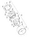
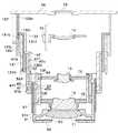
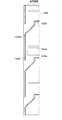
FIG. 1 is a configuration diagram of a lens barrel in a wide state at the time of shooting by the imaging apparatus according to the first embodiment of the present invention. FIG. 2 is a configuration diagram of a telescopic lens barrel at the time of photographing by the imaging apparatus according to the first embodiment of the present invention. FIG. 3 is a configuration diagram of the retracted lens barrel of the imaging apparatus according to the first embodiment of the present invention. FIG. 4 is an exploded perspective view of the lens barrel of the imaging apparatus according to the first embodiment of the present invention. FIG. 5 is a perspective view of the imaging apparatus according to the embodiment of the present invention.
図5に示すように、本撮像装置(カメラ)は、カメラ本体1に鏡筒(鏡筒ユニット)2を備える。 As shown in FIG. 5, the imaging apparatus (camera) includes a lens barrel (lens barrel unit) 2 in a
図1〜図3に示すように、本実施の形態の鏡筒は、4群の撮影レンズ群で構成される。1群レンズ11は1群筒61に、2群レンズ12は2群ホルダ72に、3群レンズ13は3群ホルダ73に保持されている。また、4群レンズ14は4群ホルダ74に保持され、不図示の駆動源により動力を供給され、光軸方向へ移動可能なように構成されている。 As shown in FIGS. 1 to 3, the lens barrel of the present embodiment is composed of four groups of photographing lenses. The
また、鏡筒構成は4段構成となっており、撮影時と沈胴時で鏡筒全長を変化させることができる。 In addition, the lens barrel configuration is a four-stage configuration, and the total length of the lens barrel can be changed between photographing and retracting.
ここで鏡筒各段の構成を説明する。 Here, the configuration of each stage of the lens barrel will be described.
固定筒ユニット20は、外側の鏡筒カバー21、その内側の回転筒22、固定筒23で構成される。鏡筒カバー21は、固定筒23と、撮像素子15を保持するホルダ24と共にビス等で固定され、カメラ本体1に保持される。 The
図6は、図4の鏡筒のうちの回転筒と固定筒部分の斜視図である。 6 is a perspective view of a rotating cylinder and a fixed cylinder part of the lens barrel of FIG.
鏡筒カバー21は、図6に示すように、ズームギアユニット80を保持している。ズームギアユニット80は、駆動源であるモータ81と、モータ81からの動力を伝達するギア82〜86を保持している。 The
このギア86は、回転筒22のギア22gとかみ合い、回転筒22は、固定筒23の外周を光軸中心に回転する。固定筒23は、内径側に直進溝23s、貫通溝23k、カム溝23cを有する。回転筒22は、内径側に直進溝22sを有する。 The
図7は、図4の鏡筒のうちの第1中間筒ユニット部分の斜視図である。 FIG. 7 is a perspective view of a first intermediate tube unit portion of the lens barrel of FIG.
鏡筒1段目となる、第1中間筒ユニット30は、第1中間回転筒31、第1中間直進筒32で構成される。 The first
ここで、第1中間直進筒32は、光軸回りの回転が規制された第1の直進筒として機能する。また、第1中間回転筒31は、第1の直進筒と嵌合して回転する第1の回転筒として機能する。 Here, the first intermediate
また、第1中間直進筒32は、固定筒23に直進案内され、光軸方向へ移動可能な移動直進筒として機能する。また、第1中間回転筒31は、移動直進筒と嵌合し、光軸方向へ移動可能な移動回転筒として機能する。 The first intermediate
第1中間直進筒32には、突起32bが設けられており、第1中間回転筒31の径方向に設けられた溝部31b(図1)と係合するので、光軸方向へ一体的に移動する。 The first intermediate
第1中間直進筒32は、内径側(内周面)に直進溝32s、貫通溝32k、カム溝32cと、外周部に直進キー部32tを有する。第1中間直進筒32は、直進キー部32tと固定筒23の直進溝23sとが係合するので、直進ガイドされる。ここで、貫通溝32kは、カム溝32cと略同一軌跡である。 The first intermediate
また、第1中間回転筒31は、外径側に駆動ピン31d、カムピン31fと、内径側に直進溝31sを有する。駆動ピン31dは、貫通溝32kを介して回転筒22の直進溝22sと係合するので、第1中間回転筒31は、回転筒22と共に回転する。カムピン31fは、固定筒23のカム溝23cと係合するので、カム溝23cの軌跡に倣って第1中間筒ユニット30が光軸方向へ移動する。 The first intermediate rotating
図8は、図4の鏡筒のうちの第2中間筒ユニット部分の斜視図である。 FIG. 8 is a perspective view of a second intermediate cylinder unit portion in the lens barrel of FIG.
鏡筒2段目となる、第2中間筒ユニット40は、上記の第1中間筒ユニット30と同様の構成となっており、第2中間回転筒(回転部材)41、第2中間直進筒(直進部材)42で構成される。 The second
ここで、第2中間直進筒42は、第1の直進筒に直進案内された第2の直進筒として機能する。また、第2中間回転筒41は、第2の直進筒と嵌合し、第1の回転筒と係合して回転する第2の回転筒として機能する。 Here, the second intermediate
第2中間直進筒42には、突起42bが設けられており、第2中間回転筒41の径方向に設けられた溝部41b(図1)と係合するので、光軸方向へ一体的に移動する。 The second intermediate
第2中間直進筒42は、内径側に直進溝42s、貫通溝42k、カム溝42cと、外周部に直進キー部42tを有する。第2中間直進筒42は、直進キー部42tと第1中間直進筒32の直進溝32sとが係合するので、直進ガイドされる。 The second intermediate
また、第2中間回転筒41は、外径側に駆動ピン41d、カムピン41fと、内径側に直進溝41sを有する。駆動ピン41dは、貫通溝32kを介して、第1中間回転筒31の直進溝31sと係合するので、第2中間回転筒41は、第1中間回転筒31と共に回転する。カムピン41fは、第1中間直進筒32のカム溝32cと係合するので、カム溝32cの軌跡に倣って第2中間筒ユニット40が光軸方向へ移動する。 The second intermediate rotating
図9は、図4の鏡筒のうちのカム筒ユニット部分の斜視図である。 FIG. 9 is a perspective view of a cam barrel unit portion of the barrel shown in FIG.
鏡筒3段目となる、カム筒ユニット50は、第3中間回転筒51、カム筒52、内直進筒53、内直進板54で構成される。 The
内直進筒53は、内径側に突起部53a、2群ホルダ72(図4)の直進ガイドを行う直進ガイド溝53s2、3群ホルダ73(図4)の直進ガイドを行う53s3を有し、外周部に1群筒ユニット60(図4)の直進ガイドを行う直進キー部53tを有する。内直進板54は、内径側に突出部54aを有し、外周部に直進キー部54tを有する。 The inner
内直進筒53は、カム筒52の前方より、内直進板54は、カム筒52の後方より、カム筒52を挟むように構成される。内直進筒53の突起部53aと、内直進板54の突出部54aが係合することで、内直進筒53と内直進板54は、それらの中間にカム筒52を挟み直進ガイドされた状態で固定される。 The inner
内直進板54は、直進キー部54tと第2中間直進筒42の直進溝42sとが係合するので、直進ガイドされる。内直進板54が直進ガイドされることにより、内直進筒53も直進ガイドされる。 The inner
また、カム筒52は、外径側に駆動ピン52d、カムピン52fを有する。駆動ピン52dは、貫通溝42kを介して、第2中間回転筒41の直進溝41sと係合するので、カム筒52は、第2中間回転筒41と共に回転する。カムピン52fは、第2中間直進筒42のカム溝42cと係合するので、カム溝42cの軌跡に倣ってカム筒ユニット50が光軸方向へ移動する。 The
第3中間回転筒51とカム筒52は、第3中間回転筒51の係合部51aと、カム筒52の突起部52aとが係合し、一体的に回転する。 The third intermediate rotating
さらに、カム筒52は、外径側に1群筒ユニット60の移動量を制御するカム52c1、内径側に2群ホルダ72の移動量を制御するカム52c2、3群ホルダ73の移動量を制御するカム52c3を備える。 Further, the
図4における1群筒ユニット60は、図1に示すように、1群筒61、1群カバー62、バリア羽根63で構成される。1群筒61の内径側には直進溝61sが設けられ、内直進筒53の直進キー部53tと係合しているので、1群筒ユニット60は、直進ガイドされる。 The first
また、1群筒61は、カム筒52のカム52c1と係合するカムピン61fを備えている。そのため1群筒ユニット60は、カム溝カム52c1の軌跡に倣って光軸方向へ移動する。バリア羽根63は、不図示の駆動手段により、使用状態では開口を開き、沈胴状態では開口を閉じる。 The
以上、説明したように、本実施の形態の鏡筒(鏡筒ユニット)2は、モータ81の駆動力により、回転筒22が回転し、それに係合している、第1中間回転筒31、第2中間回転筒41、カム筒52及び第3中間回転筒51が共に回転する。 As described above, the lens barrel (lens barrel unit) 2 according to the present embodiment includes the first intermediate rotating
また、固定筒23と、それに係合している、第1中間直進筒32、第2中間直進筒42、内直進板54及び内直進筒53は直進ガイドされ、1群筒ユニット60、2群ホルダ72、3群ホルダ73を直進ガイドしている。 Further, the fixed
これらにより構成された鏡筒を撮像装置に搭載すると、図5で示すような4段沈胴構成の鏡筒2を備えた撮像装置となる。 When the lens barrel configured as described above is mounted on the imaging apparatus, the imaging apparatus includes the
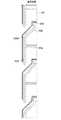
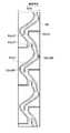
図10は、図6における固定筒の内面展開図、図11は、図7における第1中間直進筒の内面展開図、図12は、図8における第2中間直進筒の内面展開図である。また図13は、図9におけるカム筒の内面展開図である。図中、主要な個所以外は不図示としている。 10 is an inner surface development view of the fixed intermediate cylinder in FIG. 6, FIG. 11 is an inner surface development view of the first intermediate rectilinear cylinder in FIG. 7, and FIG. 12 is an inner surface development view of the second intermediate rectilinear cylinder in FIG. FIG. 13 is a developed view of the inner surface of the cam cylinder in FIG. In the figure, parts other than the main parts are not shown.
図10に示すように、固定筒23は、内径に直進溝23s、貫通溝23k、カム溝23cを有する。貫通溝23kとカム溝23cは同一の軌跡となっており、貫通溝23kは、第1中間回転筒31の駆動ピン31dが、回転筒22の直進溝22sと係合するために貫通している。 As shown in FIG. 10, the fixed
カム溝23cは、第1中間回転筒31のカムピン31fと係合する。カムピン31fは、ワイド状態となる時は、位置23Wまで移動し、テレ状態となる時は、位置23Tまで移動する。 The
図11に示すように、第1中間直進筒32は、内径に直進溝32s、貫通溝32k、カム溝32cを有する。貫通溝32kとカム溝32cは同一の軌跡となっており、貫通溝32kは、第2中間回転筒41の駆動ピン41dが、第1中間回転筒31の直進溝31sと係合するために貫通している。 As shown in FIG. 11, the first intermediate
カム溝32cは、第2中間回転筒41のカムピン41fと係合する。カムピン41fは、ワイド状態となる時は、位置32Wまで移動し、テレ状態となる時は、位置32Tまで移動する。 The
本実施の形態においては、固定筒23と第1中間直進筒32の内径カム形状は、略同一の軌跡をなしているが、カム溝、貫通溝及び直進溝の関係が成り立つのであれば異なる構成としても良い。 In the present embodiment, the inner diameter cam shapes of the fixed
図12に示すように、第2中間直進筒42は、内径に直進溝42s、貫通溝42k、カム溝42cを有する。貫通溝42kとカム溝42cは同一の軌跡となっており、貫通溝42kは、カム筒52の駆動ピン52dが、第2中間回転筒41の直進溝41sと係合するために貫通している。 As shown in FIG. 12, the second intermediate
カム溝42cは、カム筒52のカムピン52fと係合する。カムピン52fは、ワイド状態となる時は、位置42Wまで移動し、テレ状態となる時は、位置42Tまで移動する。第2中間直進筒42は、6本の直進溝42sにより内直進板54を常に直進ガイドするように構成されている。 The
図13に示すように、カム筒52は、内径に2群ホルダ72の移動量を制御するカム52c2、3群ホルダ73の移動量を制御するカム52c3を有する。カム52c2は、2群ホルダ72のカムピン72f(図1)と係合する。 As shown in FIG. 13, the
またカム52c3は、3群ホルダ73のカムピン73f(図1)と係合する。カムピン72f、73fは、それぞれワイド状態となる時は、位置52c2W、52c3Wまで移動し、テレ状態となる時は、位置52c2T、52c3Tまで移動する。 The cam 52c3 engages with a
先に説明したように、カム筒52は、内径側に各レンズ群の直進ガイドとなる、内直進筒53と内直進板54が光軸方向前後に挟まれるように配置されるので、カム筒52の光軸方向の移動により、内直進筒53及び内直進板(直進部材)54は共に移動する。 As described above, the
そのため、第1中間回転筒31と第1中間直進筒32の結合関係のような、バヨネット結合構造を持たなくても良い。そのため、図13に示すように、カム筒52の内径側に配置されるカムは、カム筒52の光軸方向の長さ52Bを最小にすることができる。 Therefore, it is not necessary to have a bayonet coupling structure such as the coupling relationship between the first intermediate rotating
また、本実施の形態においては、図10〜図13に示したようなカム溝及び貫通溝の軌跡となっているが、カム溝、貫通溝及び直進溝の関係が成り立つのであれば、これ以外にも自由に軌跡を設定することも可能である。 Further, in the present embodiment, the locus of the cam groove and the through groove as shown in FIGS. 10 to 13 is used. However, if the relationship of the cam groove, the through groove, and the straight groove is satisfied, other than this It is also possible to set the trajectory freely.
さらに、本実施の形態においては、中間筒ユニットを2つ(第1中間筒ユニット30、第2中間筒ユニット40)配置して4段沈胴鏡筒を構成したが、この実施の形態に限らず、例えば、中間筒ユニットを1つ配置すると、3段沈胴鏡筒を構成することができる。 Further, in the present embodiment, two intermediate cylinder units (first
同様に、中間筒ユニットを3つ配置すると、5段沈胴鏡筒を構成することができる。このように中間筒ユニットの数を変更することで、鏡筒の段数を自由に変更することもできる。 Similarly, when three intermediate cylinder units are arranged, a five-stage collapsible lens barrel can be configured. In this way, the number of stages of the lens barrel can be freely changed by changing the number of intermediate cylinder units.
(第2の実施の形態)
以下に、本発明の第2の実施の形態を示す。(Second Embodiment)
Hereinafter, a second embodiment of the present invention will be described.
図14は、本発明の第2の実施の形態に係る撮像装置の撮影時のワイド状態の鏡筒の構成図である。また、図15は、本発明の第2の実施の形態に係る撮像装置の鏡筒の固定筒及びギアユニットの斜視図、図16は、本発明の第2の実施の形態に係る撮像装置の鏡筒の第1中間筒ユニットの斜視図である。 FIG. 14 is a configuration diagram of the lens barrel in the wide state at the time of shooting by the imaging apparatus according to the second embodiment of the present invention. FIG. 15 is a perspective view of a fixed barrel and a gear unit of a lens barrel of an imaging apparatus according to the second embodiment of the present invention, and FIG. 16 is an imaging apparatus according to the second embodiment of the present invention. It is a perspective view of the 1st intermediate cylinder unit of a lens-barrel.
本実施の形態においては、撮影レンズ群(1群レンズ11〜4群レンズ14)、第2中間筒ユニット40、カム筒ユニット50、及び1群筒ユニット60は、第1の実施の形態と同様の構成となっている。 In the present embodiment, the photographing lens group (the
ここで鏡筒各段の構成を説明する。 Here, the configuration of each stage of the lens barrel will be described.
図15において、固定筒123は、撮像素子15を保持するホルダ24と共にビス等で固定され、カメラ本体1に保持される。 In FIG. 15, the fixed
また、本実施の形態では、ズームギアユニット180は、駆動源であるモータ181と、モータ81からの動力を伝達するギア182〜186と、長ギア187で構成され、固定筒123のギア保持部123nで長ギア187を保持している。また、固定筒123は、内径側に直進溝123s、カム溝123cを有する。 In the present embodiment, the
図16において、鏡筒1段目となる、第1中間筒ユニット130は、第1中間回転筒131、第1中間直進筒132で構成される。第1中間直進筒132には、突起132bが設けられており、第1中間回転筒131の径方向に設けられた溝部131b(図14)と係合するので、光軸方向へ一体的に移動する。 In FIG. 16, the first
第1中間直進筒132は、第1の実施の形態と同様に、内径側に直進溝132s、貫通溝132k、カム溝132cと、外周部に直進キー部132tを有する。第1中間直進筒132は、直進キー部132tと固定筒123の直進溝123sとが係合するので、直進ガイドされる。 As in the first embodiment, the first intermediate
また、第1中間回転筒131は、外径側に駆動ギア131g、カムピン131fと、内径側に直進溝131sを有する。駆動ギア131gは、長ギア187と係合するので、第1中間回転筒131は回転する。カムピン131fは、固定筒123のカム溝123cと係合するので、カム溝123cの軌跡に倣って第1中間筒ユニット130が光軸方向へ移動する。 The first intermediate
鏡筒2段目となる第2中間筒ユニット40、鏡筒3段目となるカム筒ユニット50及び1群筒ユニット60は、第1の実施の形態と同様に構成される。 The second
図17は、図15における固定筒の内面展開図であり、図18は、図16における第1中間直進筒の内面展開図である。図中、主要な個所以外は不図示としている。 17 is an inner surface development view of the fixed cylinder in FIG. 15, and FIG. 18 is an inner surface development view of the first intermediate rectilinear cylinder in FIG. In the figure, parts other than the main parts are not shown.
図17に示すように、固定筒123は、内径側に直進溝123s、カム溝123c及びギア保持部123nを有する。カム溝123cは、第1中間回転筒131のカムピン131fと係合する。カムピン131fは、ワイド状態となる時は、位置123Wまで移動し、テレ状態となる時は、位置123Tまで移動する。 As shown in FIG. 17, the fixed
図18に示すように、第1中間直進筒132は、内径に直進溝132s、貫通溝132k、カム溝132cを有する。貫通溝132kとカム溝132cは同一の軌跡となっており、貫通溝132kは、第2中間回転筒41の駆動ピン41dが、第1中間回転筒131の直進溝131sと係合するために貫通している。 As shown in FIG. 18, the first intermediate
カム溝132cは、第2中間回転筒41のカムピン41fと係合する。カムピン41fは、ワイド状態となる時は、位置132Wまで移動し、テレ状態となる時は、位置132Tまで移動する。 The
本実施の形態においては、固定筒123と第1中間直進筒132の内径カム形状は、略同一の軌跡をなしているが、カム溝、貫通溝及び直進溝の関係が成り立つのであれば異なる構成としても良い。また、貫通溝の側壁にカム溝を設ける構成であっても良い。 In the present embodiment, the inner diameter cam shapes of the fixed
さらに、本実施の形態においても、第1の実施の形態と同様、中間筒ユニットを2つ配置して4段沈胴鏡筒を構成したが、この実施の形態に限らず、例えば、中間筒ユニットを1つ配置すると、3段沈胴鏡筒を構成することができる。 Further, in the present embodiment, as in the first embodiment, two intermediate cylinder units are arranged to form a four-stage retractable lens barrel. However, the present invention is not limited to this embodiment. For example, the intermediate cylinder unit If one is arranged, a three-stage retractable lens barrel can be configured.
同様に中間筒ユニットを3つ配置すると、5段沈胴鏡筒を構成することができる。このように、中間筒ユニットの数を変更することで、鏡筒の段数を自由に変更することもできる。 Similarly, when three intermediate cylinder units are arranged, a five-stage collapsible lens barrel can be configured. Thus, the number of stages of the lens barrel can be freely changed by changing the number of intermediate tube units.
1 カメラ本体
2 鏡筒
11 1群レンズ
12 2群レンズ
13 3群レンズ
14 4群レンズ
15 撮像素子
23 固定筒
31 第1中間回転筒
31s 係合溝
32 第1中間直進筒
32c カム溝
32k 貫通溝
32s 直進溝
41 第2中間回転筒
41s 直進溝
42 第2中間直進筒
42c カム溝
50 カム筒ユニット
51 第3中間回転筒
52 カム筒
52d 駆動ピンDESCRIPTION OF
Claims (5)
Translated fromJapaneseモータからの動力を受けるギアが周方向に形成され、光軸回りに回転する回転筒と、
前記回転筒の内側にある筒であって、撮像素子を有するホルダとともに撮像装置に保持され、光軸回りの回転が規制された固定筒と、
固定筒の内側にある筒であって、前記回転筒と係合して回転する第1の回転筒と、
第1の回転筒の内側にある筒であって、前記第1の回転筒と係合して光軸方向に一体に移動可能で、かつ前記固定筒に直進案内された第1の直進筒と、
前記第1の回転筒の内側にある筒であって、前記第1の回転筒と係合して回転する第2の回転筒と、
前記第2の回転筒の内側にある筒であって、前記第2の回転筒と係合して光軸方向に一体に移動可能で、かつ前記第1の直進筒に直進案内された第2の直進筒と、
前記第2の直進筒の内側にあるユニットであって、カム筒及びその内側にある第3の直進筒を有し、前記第2の回転筒と係合して光軸方向に一体に移動可能で、かつ前記第2の直進筒に直進案内されたカムユニットとを有し、
前記固定筒は、前記第1の回転筒を光軸方向に移動させるためのカム溝を有し、
前記第1の直進筒は、前記第2の回転筒を光軸方向に移動させるためのカム溝を有し、
前記第2の直進筒は、前記カム筒ユニットを光軸方向に移動させるためのカム溝を有し、
前記複数のレンズ保持部のうち、少なくとも1つのレンズ保持部は前記カム筒ユニットの外側にあり、少なくとも1つの他のレンズ保持部は前記カム筒ユニットの内側にあり、
前記カム筒は、前記複数のレンズ保持部のそれぞれと係合するための複数のカム溝を有し、当該複数のカム溝のうち、少なくとも1つのカム溝は前記カム筒の内側に、少なくとも1つの他のカム溝は前記カム筒の外側に設けられ、
前記第3の直進筒は、前記複数のレンズ保持部のそれぞれを直進案内するための複数のガイド部を有し、当該複数のガイド部のうち少なくとも1つのガイド部は、前記第3の直進筒の外周部に設けられた突部であり、前記カム筒の外側にある前記少なくとも1つのレンズ保持部と係合することを特徴とする撮像装置。A plurality of lens holding portions for holding a plurality of photographing lens groups,
A gear that receives power from the motor is formed in the circumferential direction, and rotates around the optical axis;
A cylinder inside the rotating cylinder, held in the imaging device together with a holder having an imaging element, and a fixed cylinder whose rotation around the optical axis is restricted;
A first rotating cylinder that is engaged with and rotates with the rotating cylinder;
A cylinder inside the first rotary cylinder, which is engaged with the first rotary cylinder, can move integrally in the optical axis direction, and is linearly guided by the fixed cylinder; ,
A second rotary cylinder that is inside the first rotary cylinder and rotates by engaging with the first rotary cylinder;
A second cylinder that is located inside the second rotary cylinder, engages with the second rotary cylinder, can move integrally in the optical axis direction, and is guided in a straight line by the first straight cylinder. and the rectilinear barrelof,
A unit inside the second rectilinear cylinder, having a cam cylinder and a third rectilinear cylinder inside the cam cylinder, engages with the second rotary cylinder and can move integrally in the optical axis direction. And a cam unit guided in a straight line by the second straight cylinder ,
The fixed cylinder has a cam groove for moving the first rotating cylinder in the optical axis direction,
The first rectilinear cylinder has a cam groove for moving the second rotating cylinder in the optical axis direction,
The second rectilinearbarrelhasa cam groovefor moving the cam barrel unitin the optical axis direction,
Among the plurality of lens holding portions, at least one lens holding portion is outside the cam barrel unit, and at least one other lens holding portion is inside the cam barrel unit,
The cam cylinder has a plurality of cam grooves for engaging with each of the plurality of lens holding portions, and at least one of the plurality of cam grooves is at least one inside the cam cylinder. Two other cam grooves are provided outside the cam cylinder,
The third rectilinear tube has a plurality of guide portions for linearly guiding each of the plurality of lens holding portions, and at least one guide portion of the plurality of guide portions is the third rectilinear tube. An image pickup apparatusthat is a protrusion provided on the outer peripheral portion of the cam cylinder and engages with theat least one lens holding portion outside the cam cylinder .
前記カム筒の前記駆動ピンは、前記貫通溝を貫通して、前記第2の回転筒の直進溝と係合し、前記カム筒が前記第2の回転筒と共に回転するように構成したことを特徴とする請求項1乃至3のいずれか一項に記載の撮像装置。The second rectilinear cylinder includes a cam groove that engages with a drive pin that protrudes outside the cam cylinder of the cam cylinder unit, and a through groove that has substantially the same locus as the cam groove with which the drive pin engages. And
The drive pin of the cam cylinder is configured to pass through the through groove and engage with a rectilinear groove of the second rotary cylinder so that the cam cylinder rotates together with the second rotary cylinder. The imaging apparatus accordingto any one of claims 1 to3, wherein the imaging apparatus is characterized.
Priority Applications (3)
| Application Number | Priority Date | Filing Date | Title |
|---|---|---|---|
| JP2008203183AJP5483842B2 (en) | 2008-08-06 | 2008-08-06 | Imaging device |
| US12/535,493US8654453B2 (en) | 2008-08-06 | 2009-08-04 | Image pickup apparatus |
| CN2009101636244ACN101644819B (en) | 2008-08-06 | 2009-08-06 | Image pickup apparatus |
Applications Claiming Priority (1)
| Application Number | Priority Date | Filing Date | Title |
|---|---|---|---|
| JP2008203183AJP5483842B2 (en) | 2008-08-06 | 2008-08-06 | Imaging device |
Publications (2)
| Publication Number | Publication Date |
|---|---|
| JP2010039285A JP2010039285A (en) | 2010-02-18 |
| JP5483842B2true JP5483842B2 (en) | 2014-05-07 |
Family
ID=41652694
Family Applications (1)
| Application Number | Title | Priority Date | Filing Date |
|---|---|---|---|
| JP2008203183AExpired - Fee RelatedJP5483842B2 (en) | 2008-08-06 | 2008-08-06 | Imaging device |
Country Status (3)
| Country | Link |
|---|---|
| US (1) | US8654453B2 (en) |
| JP (1) | JP5483842B2 (en) |
| CN (1) | CN101644819B (en) |
Families Citing this family (36)
| Publication number | Priority date | Publication date | Assignee | Title |
|---|---|---|---|---|
| JP5566164B2 (en)* | 2010-03-31 | 2014-08-06 | キヤノン株式会社 | Lens barrel and imaging device |
| JP5765956B2 (en)* | 2011-02-03 | 2015-08-19 | キヤノン株式会社 | Lens barrel and imaging device |
| KR101817651B1 (en) | 2011-02-11 | 2018-02-21 | 삼성전자주식회사 | Zoom lens barrel assembly |
| CN103941375B (en)* | 2013-01-18 | 2016-08-17 | 佳能株式会社 | Lens barrel and camera head |
| KR101634516B1 (en) | 2013-06-13 | 2016-06-28 | 코어포토닉스 리미티드 | Dual aperture zoom digital camera |
| US9857568B2 (en) | 2013-07-04 | 2018-01-02 | Corephotonics Ltd. | Miniature telephoto lens assembly |
| JP2016523389A (en) | 2013-07-04 | 2016-08-08 | コアフォトニクス リミテッド | Compact telephoto lens assembly |
| JP6270370B2 (en) | 2013-08-08 | 2018-01-31 | キヤノン株式会社 | Lens barrel and imaging device |
| US9392188B2 (en) | 2014-08-10 | 2016-07-12 | Corephotonics Ltd. | Zoom dual-aperture camera with folded lens |
| CN112433331B (en) | 2015-01-03 | 2022-07-08 | 核心光电有限公司 | Miniature telephoto lens module and camera using the same |
| RU2648003C1 (en)* | 2016-12-14 | 2018-03-21 | Публичное акционерное общество "Красногорский завод им. С.А. Зверева" | Lens to change the size of the image |
| KR102212611B1 (en) | 2017-02-23 | 2021-02-05 | 코어포토닉스 리미티드 | Folded camera lens designs |
| CN107390392A (en)* | 2017-07-24 | 2017-11-24 | 昆山国显光电有限公司 | Array substrate detection equipment and array base palte detection method |
| US11336830B2 (en) | 2019-01-03 | 2022-05-17 | Corephotonics Ltd. | Multi-aperture cameras with at least one two state zoom camera |
| WO2021033047A1 (en) | 2019-08-21 | 2021-02-25 | Corephotonics Ltd. | Low total track length for large sensor format |
| US12072609B2 (en) | 2019-09-24 | 2024-08-27 | Corephotonics Ltd. | Slim pop-out cameras and lenses for such cameras |
| US11656538B2 (en) | 2019-11-25 | 2023-05-23 | Corephotonics Ltd. | Folded zoom camera module with adaptive aperture |
| WO2021140989A1 (en)* | 2020-01-06 | 2021-07-15 | 株式会社ニコン | Lens barrel and optical apparatus |
| US11689708B2 (en) | 2020-01-08 | 2023-06-27 | Corephotonics Ltd. | Multi-aperture zoom digital cameras and methods of using same |
| CN111622970A (en)* | 2020-05-13 | 2020-09-04 | 漳州立达信光电子科技有限公司 | Air circulation fan |
| US11770609B2 (en) | 2020-05-30 | 2023-09-26 | Corephotonics Ltd. | Systems and methods for obtaining a super macro image |
| KR102765964B1 (en) | 2020-07-22 | 2025-02-07 | 코어포토닉스 리미티드 | Folded camera lens design |
| CN119414645A (en) | 2020-07-31 | 2025-02-11 | 核心光电有限公司 | camera |
| EP4127788A4 (en)* | 2020-09-18 | 2024-06-19 | Corephotonics Ltd. | Pop-out zoom camera |
| US12271105B2 (en) | 2020-11-05 | 2025-04-08 | Corephotonics Ltd. | Scanning Tele camera based on two prism field of view scanning |
| KR20250008791A (en) | 2020-12-01 | 2025-01-15 | 코어포토닉스 리미티드 | Folded camera with continuously adaptive zoom factor |
| CN112526700B (en)* | 2020-12-21 | 2023-05-12 | 维沃移动通信有限公司 | Camera module and electronic equipment |
| CN117425062A (en) | 2021-01-25 | 2024-01-19 | 核心光电有限公司 | Lens system for compact digital camera |
| WO2022200965A1 (en) | 2021-03-22 | 2022-09-29 | Corephotonics Ltd. | Folded cameras with continuously adaptive zoom factor |
| KR20240012438A (en) | 2021-06-23 | 2024-01-29 | 코어포토닉스 리미티드 | Compact folded tele camera |
| KR102685591B1 (en) | 2021-09-23 | 2024-07-15 | 코어포토닉스 리미티드 | Large aperture continuous zoom folded telecamera |
| CN119414565A (en) | 2021-11-02 | 2025-02-11 | 核心光电有限公司 | Camera module and mobile device |
| CN120315167A (en) | 2021-12-14 | 2025-07-15 | 核心光电有限公司 | Large aperture compact scan telephoto camera |
| US12348870B2 (en) | 2022-04-09 | 2025-07-01 | Corephotonics Ltd. | Spin-out 360-degree camera for smartphone |
| US12368960B2 (en) | 2022-08-05 | 2025-07-22 | Corephotonics Ltd. | Systems and methods for zoom digital camera with automatic adjustable zoom field of view |
| JP2025501848A (en) | 2022-12-20 | 2025-01-24 | 珠海市榕昇科技有限公司 | Variable magnification sight |
Family Cites Families (9)
| Publication number | Priority date | Publication date | Assignee | Title |
|---|---|---|---|---|
| CN1069974C (en)* | 1995-02-08 | 2001-08-22 | 佳能株式会社 | Lens tube and optical instrument |
| JP3344193B2 (en)* | 1996-01-31 | 2002-11-11 | ミノルタ株式会社 | Multi-stage lens barrel |
| JP3811281B2 (en)* | 1997-12-10 | 2006-08-16 | オリンパス株式会社 | Zoom lens barrel |
| JP2000111786A (en)* | 1998-10-02 | 2000-04-21 | Canon Inc | Zoom lens barrel |
| JP2003021776A (en)* | 2001-07-10 | 2003-01-24 | Olympus Optical Co Ltd | Zoom lens frame and zoom camera |
| JP4256689B2 (en)* | 2003-02-12 | 2009-04-22 | Hoya株式会社 | Lens barrel switching movement structure |
| JP4724363B2 (en)* | 2003-11-05 | 2011-07-13 | キヤノン株式会社 | Lens barrel and imaging device |
| JP4497907B2 (en)* | 2003-12-12 | 2010-07-07 | キヤノン株式会社 | Lens device and camera |
| JP4623997B2 (en)* | 2004-04-27 | 2011-02-02 | 日東光学株式会社 | Lens barrel device |
- 2008
- 2008-08-06JPJP2008203183Apatent/JP5483842B2/ennot_activeExpired - Fee Related
- 2009
- 2009-08-04USUS12/535,493patent/US8654453B2/ennot_activeExpired - Fee Related
- 2009-08-06CNCN2009101636244Apatent/CN101644819B/ennot_activeExpired - Fee Related
Also Published As
| Publication number | Publication date |
|---|---|
| US8654453B2 (en) | 2014-02-18 |
| CN101644819A (en) | 2010-02-10 |
| JP2010039285A (en) | 2010-02-18 |
| US20100033844A1 (en) | 2010-02-11 |
| CN101644819B (en) | 2013-02-13 |
Similar Documents
| Publication | Publication Date | Title |
|---|---|---|
| JP5483842B2 (en) | Imaging device | |
| JP4732044B2 (en) | Lens barrel and imaging device | |
| JP5011793B2 (en) | Lens barrel and imaging device | |
| JPH09211290A (en) | Multistage extension lens barrel | |
| JPH0727963A (en) | Zoom lens device | |
| JP5448630B2 (en) | Lens barrel and optical apparatus having the same | |
| US6819502B2 (en) | Structure of a zoom lens barrel | |
| EP2203772B1 (en) | Lens apparatus and imaging apparatus | |
| JP5197218B2 (en) | Imaging device | |
| JP7128889B2 (en) | lens barrel | |
| JP2010049022A (en) | Lens driving device, lens barrel, and camera | |
| JP2017126013A (en) | Lens barrel and imaging device | |
| US7242535B2 (en) | Zoom lens barrel including a rotatable cam ring | |
| JP2014106264A (en) | Lens barrel, and imaging apparatus | |
| JP7191660B2 (en) | Lens barrels and optical equipment | |
| JP2013156561A (en) | Lens barrel and imaging apparatus including the same | |
| JP2003177297A (en) | Optical equipment | |
| JP5397774B2 (en) | Lens barrel, imaging device, and electronic device | |
| JP2012145827A (en) | Zoom lens barrel and digital camera | |
| JP4808390B2 (en) | Lens barrel and camera | |
| JP3422159B2 (en) | Sliding protection member for flexible substrates | |
| JP6645688B2 (en) | Optical equipment | |
| JPH09211284A (en) | Lens barrel | |
| JP2012247719A (en) | Lens barrel and camera | |
| JP4648778B2 (en) | Lens barrel drive mechanism |
Legal Events
| Date | Code | Title | Description |
|---|---|---|---|
| A621 | Written request for application examination | Free format text:JAPANESE INTERMEDIATE CODE: A621 Effective date:20110802 | |
| A977 | Report on retrieval | Free format text:JAPANESE INTERMEDIATE CODE: A971007 Effective date:20120615 | |
| A131 | Notification of reasons for refusal | Free format text:JAPANESE INTERMEDIATE CODE: A131 Effective date:20120731 | |
| A521 | Request for written amendment filed | Free format text:JAPANESE INTERMEDIATE CODE: A523 Effective date:20121001 | |
| A131 | Notification of reasons for refusal | Free format text:JAPANESE INTERMEDIATE CODE: A131 Effective date:20130514 | |
| A521 | Request for written amendment filed | Free format text:JAPANESE INTERMEDIATE CODE: A523 Effective date:20130708 | |
| TRDD | Decision of grant or rejection written | ||
| A01 | Written decision to grant a patent or to grant a registration (utility model) | Free format text:JAPANESE INTERMEDIATE CODE: A01 Effective date:20140121 | |
| A61 | First payment of annual fees (during grant procedure) | Free format text:JAPANESE INTERMEDIATE CODE: A61 Effective date:20140218 | |
| R151 | Written notification of patent or utility model registration | Ref document number:5483842 Country of ref document:JP Free format text:JAPANESE INTERMEDIATE CODE: R151 | |
| LAPS | Cancellation because of no payment of annual fees |